

Page 1
Page 2
Page 3

- 1 -
HLP-C
+
Inverters
Contents
Ⅰ.Introduction………………………………………… 1
1.Checks upon Delivery …………………………………………2
2.Nameplate Information of HLP-C+ Series……………………3
Ⅱ. Safety Precautions ……………………………… 4
1.Before the Power Up ………………………………………… 4
2.During the Power Up………………………………………… 6
3.Duing the Operation …………………………………………… 6
Ⅲ. Standard Specifications ………………………… 8
1.Particular Specications …………………………………… 8
2.General Specifications ……………………………………… 8
Ⅳ. Storage and Installation………………………… 10
1.Storage………………………………………………………… 10
2.Installation Locationand Environment …………………… 10
3.Installation Space and Direction …………………………… 10
Ⅴ. Wiring ……………………………………………… 12
1.Main Circuit Schematic Diagram ………………………… 12
2.Terminals Description ……………………………………… 13
3.Basic Connection Diagram ………………………………… 14
4.Precautions on Wiring ………………………………………15
Ⅵ. Instruction of the digital operator……………… 18
1.Description Of The Digital Operator ……………………… 18
2.Display Description of Indication Status ………………… 18
3.Operation Instruction ………………………………………19
Ⅶ. Commissioning ………………………………… 20
1.Important Checks Before the Commissioning …………… 20
2.Commissioning Methods …………………………………… 20
Page 4

- 2 -
HLP-C
+
Inverters
Ⅷ. Function List ……………………………………… 21
Ⅸ. Descriptions of Functions ………………………28
Ⅹ. Care & Maintenance, Fault Information
and Troubleshooting ……………………………… 80
1.Precautions about Inspection and Maintenance ………… 80
2.Periodical Inspection and Maintenance items…………… 80
3.Fault indication and troubleshooting ……………………… 81
4.Faults and Analysis ………………………………………… 85
Ⅺ. Selection of Peripheral Devices and
Disposition………………………………………… 88
1.Options ……………………………………………………… 88
2.D isposition ………………………………………………… 89
Ⅻ. Appendices ……………………………………… 91
Appendix 1:
Application demonstrations ………………… 91
Appendix 2:
External Appearance and
Installation Dimensions …………………… 93
Appendix 3:
User’s Records and Feedback ……………… 95
Page 5
- 1 -
HLP-C
+
Inverters
I.Introduction
Thank you for purchasing and using the general-purpose inverter
of HLP- C+ Series of multi-functions and high performance.
The inverter of HLP- C+ Series has been developed on basis
of HLP-A Series keeping the main functions of HLP-A Series
and with additional functions on request of customers as well
as smaller size. So the inverter of HLP- C+ Series features more
compact and more powerful functions.
Please read caref ully t he ope ration manual before put t he
inverter to use so as to correctly install and operate the inverter,
give full play to its functions and ensure the safety. Please keep
the operation manual handy for future reference, maintenance,
inspection and repair.
Due to the inverter of a kind of electrical and electronic product
it mu st be installed, tested and adjusted with parameters by
specialized engineering persons of motor. The marks of
and other simbols in the manual remind you of the
safet y and prevention caustions during the tra nsportat ion,
instal lation, r unning and inspect ion. Please follow the se
instructions to make sure the safe use of the inverter. In case of
any doubt please contact our local agent for consultation. Our
professional persons are willing and ready to serve you.
The manual is subject to change without notice.
Danger
Caution
Danger
indicates wrong use may kill or injure people.
Caution
indicates wrong use may damage the inverter
or mechanical system.
Danger
● Be sure to turn off the input power supply before wiring.
● Do not touch any internal ecectrical circuit or component
when the charging lamp is still on after the AC power supply
is disconnected, which means the inver ter still has high
voltage inside and it is very dangerous.
Page 6
- 2 -
HLP-C
+
Inverters
● Do not check components and signals on the circuit boards.
● Do not dissemble or modify the any internal connecting
cord, wiring or component of the inverter by yourself.
● Be sure to make correct ground connection of the ear th
terminal of the inverter.
● Neve r remo d e l it or exc h a nge c ont r ol bo a rd s and
components by yourself. It may expose you to an electrical
shock or explosion, etc.
Caution
● Do not make any voltage with standing test with any
component inside the inverter. These semi-conductor parts
are subject to the damange of high voltage.
● Never connect the AC main circuit power supply to output
terminals U.V W. of the inverter.
● The main electric circuit boards of CMOS and IC of the
inver ter are subject to the effect and damage of static
electricity. Donn’t touch the main circuit boards.
● Installation, testing and maintenance must be performed by
qualied professional personnel.
● The inverter should be discarded as industrial waste. Avoid
burning.
( 1 ) Checks upon Delivery
The inverter has been strictly and well packed before ex-work.
In consideration of various factors during the transportation
special attention should be paid to the following points before
the assembly and installation. If there is anything abnormal
please notify the dealer or the relevant people of our company.
● Check if the inverter has got any damage or defor mation
during the transportation.
● Check if there is one piece of HLP-C+ series inverter and one
copy of the instruction manual available after unpacking it.
● C heck t h e information on t h e namepla t e to s ee if t he
specifications meet your order (Operating voltage and KAV
value).
Page 7
- 3 -
HLP-C
+
Inverters
MODE: HLPC+01D543B
INPUT: 3PH380V50Hz/60Hz
OUTPUT: 3PH380V4.0A1.5KW
Freq Range: 0.1-600Hz
HLP ELECTRONICS CO., LTD
Type:HLP C
+
01D5 43 B
Hardware Version
Voltage Rating,
43 means 3-phase380V
Inverter Capacity,
01D5 means 1.5KW
Series No.
Trade Mark
● Check if there is something wrong on the inner parts, wiring
and circuit board.
● Check if each terminal is tightly locked andif there is any
foreign article insie the inverter.
● Check if the operator buttons are all right.
● Check if the optional components you ordered is contained in
it.
● Check if there is a certicate of qualication and a warranty
card.
( 2 ) Nameplate Information of HLP-C+ Series
Page 8
- 4 -
HLP-C
+
Inverters
Caution
● Check to be sure that the voltage of the main circuit AC
power supply matches the input voltage of the inverter.
Caution
●
E
symbol is the ground terminal. Be sure to make correct
ground connection of the earth terminals of the motor and
the inverter for safety. E can't be connected to Line zero.
● No contactor should be installed between the power supply
and theinverter to use it for sta rting or stopping of the
inverter. Otherwise it will affect the service life of the
inverter.
Danger
● R.S.T terminals are power input terminals, never mixed with
U.V.W terminals. Be sure that the wiring of the main circuit
is correct. Otherwise it will cause damages of the inverter
when the power is delivered to it.
● Do not carry the front cover of the inverter directly when
handling, It should be handled with the base to prevent
the fall off of the front cover and avoid the dropping of the
inverter,which may possibly cause the injuries to people and
the damages to the inverter.
● Mount the inver ter on a metal or ot her noncombustible
material to avoid the risk of re.
● Install the inverter in a safe site, avoid high temperature,
direct sunlight, humid air or water.
● Keep the inverter from the reach of children or persons not
concerned.
II.Safety Precautions
⑴ Before the Power Up
Caution
Page 9
- 5 -
HLP-C
+
Inverters
● The inverter can only be used at the places accredited by
our company. Any unauthorized working environment may
have the risks of re, gas explosion, electric shock and other
incidents.
● Install a cooling fan or other cooling device when installing
more than one inverters in the same enclosure so that the
temperature inside the enclosure be kept below 40℃ to
avoid overheat or the risk of re. .
● Be sure to turn off the power supply before dissembling or
assembling the operation keyboard and fxing the front cover
to avoid bad contact causing faults or non-display of the
operator.
● Do not install the inverter in a space with explosive gas to
avoid the risk of explosion.
● If the inverter is used at or above 1000m above seal level,
the cooling efficiency will be worse, so please run it by
changing down.
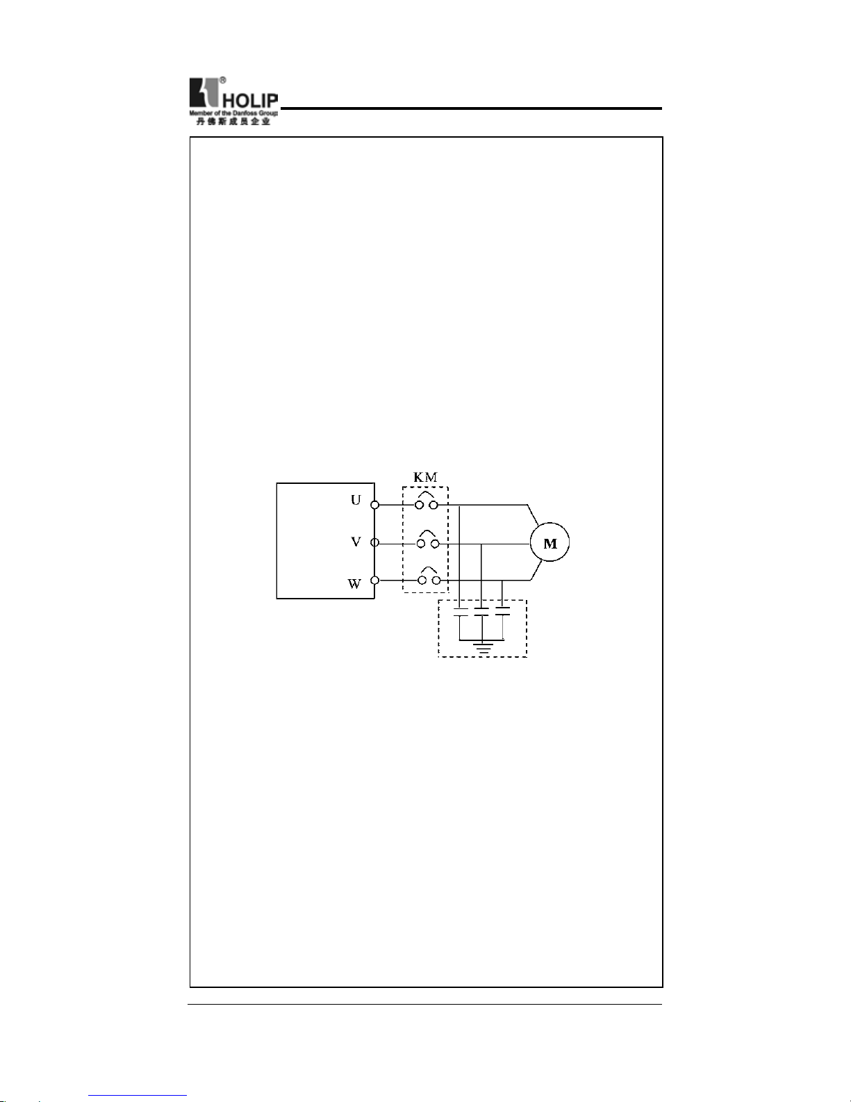
● Do not install any contactor and other components of related
capacitor o var istor on the out put side of the inverter.
Other wise it will cause malfunctions and damages of
components of the inverter.
● Do not install any switching component like air breaker
or contactor on the output side of the inverter. If any of
such components must be installed because of process
and other needs, it must be ensured that the inverter has
no output when the switch takes actions. In addition, it is
forbidden to install any for improvement of power factors
or varistors against thunder on the output side. Otherwise it
Inverter
X
X
Page 10
- 6 -
HLP-C
+
Inverters
⑵ During the Power Up
Danger
● Do not plug the connectors (CONNECTOR)of the inverter
when it is in the delivery of current to avoid any surge into
the main control board due to plugging, which might cause
the damage of the inverter.
● Always have the protective cover in place before delivery of
current to avoid electrical shock injury.
⑶ During the Operation
will cause malfunctions, tripping protecton and damages of
components of the inverter. Please remove them as shown in
the above diagram.
● The function of STOP switch is only valid after it is set. Its
use is different with the emergency stop switch. Be careful
when using it.
● It will affect the service life of the inverter if a contact is
connected to the front end of input of the inverter to control
its starting and stopping. Generally it is required to control
it through FOR or REV terminals. Special attention should
be paid to its use in the case of frequent starts and stops.
● Please use an independent power supply for the inverter.
Do avoid using the common power supply with an electric
welder and other equipment. Otherwise it will cause the
protection or damage of the inverter.
Danger
● Never connect or disconnect the motor set while the inverter
is in running. Otherwise it will cause overcurrent trip and
even burn up the main circuit of the inverter.
● Never remove the front cover of t he inver ter while t he
inverter is powered on to avoid any injury of electric shock..
● Do not come close to the machine when the fault restart
function is used to avoid anything unexpected. The motor
may automatically restart after stopping running
Page 11
- 7 -
HLP-C
+
Inverters
Caution
● Do not touch the heat sink, braking resistor, or other heat
elements. These can become very hot.
● Be sure that the motor and machine is within the applicable
speed ranges before starting operation because the inverter
is quite easy to run from lower speed to higher speed.
● Do not check the signals on circuit boards while the inverter
is running to avoid danger.
● Be careful when changing the inverter settings. The inverter
has been adjusted and set before ex-work. Do not adjust it
wantonly. Please make proper adjustments according to the
required functions.
● Do consider the vibration, noise and the speed limit of the
motor bearings and the mechanical devices when the inverter
is running at or above the frequency of 50Hz.
Page 12
- 8 -
HLP-C
+
Inverters
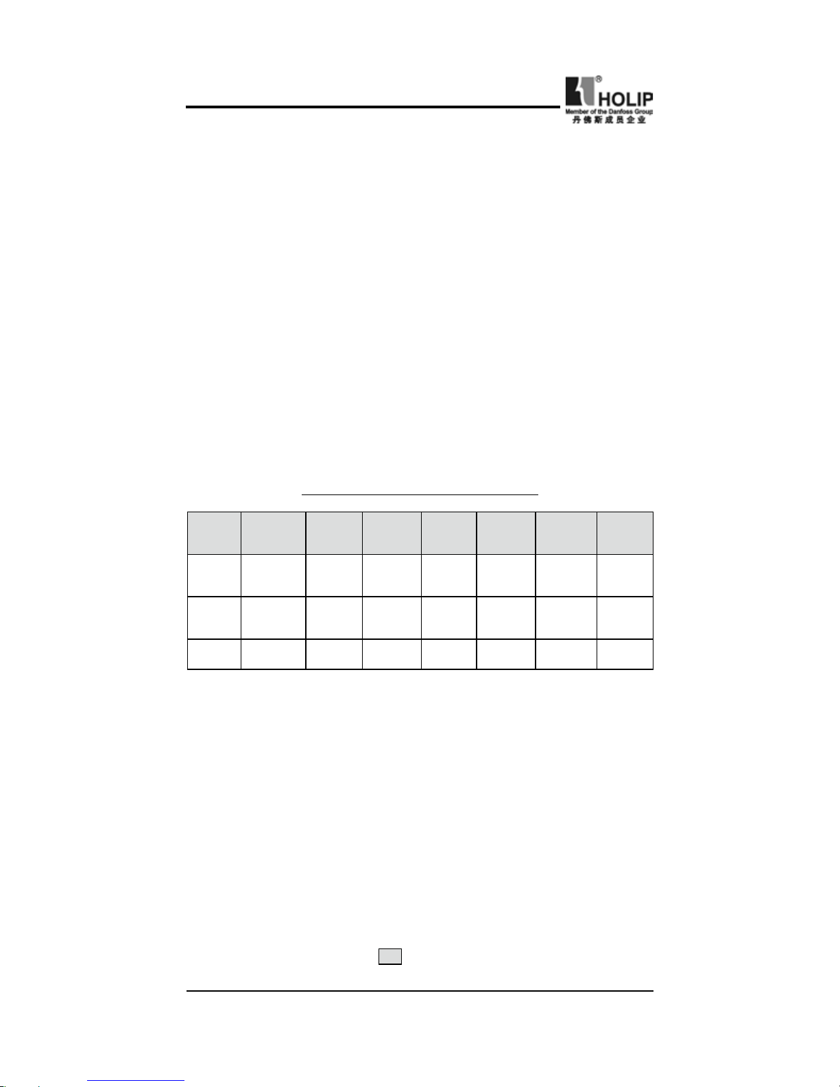
III. Standard Specifications
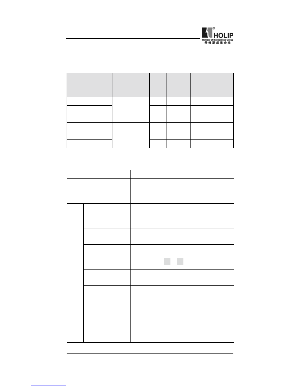
⑴ Particular Specifications
Type Input Voltage
Power
(KW)
Inverter
Capacity
(
KVA
)
Output
Current
(A)
Suitable
Motor
(
KW
)
HLPC+0D7543B
3φ380V
50/60Hz
0.75 2.2 2.7 0.75
HLP C+01D543B 1.5 3.2 4.0 1.5
HLP C+02D243B 2.2 4.0 5.0 2.2
HLP C+00D423B
Single &
Three Phase
220V 50/60Hz
0.4 1.0 2.5 0.4
HLP C+0D7523B 0.75 2.0 5.0 0.75
HLP C+01D523B 1.5 2.8 7.0 1.5
⑵ General Specifications
Descriptions HLP- C
+
Control Type SPWM
Input Power
400V class:345~440V
;
230V class:170~230V
Range 0.1~600.0Hz
Acuracy
Digital:0.01%(-10~40
℃);
Analogue:0.1%(25±10
℃)
Setting Resolution
Digital:0.1Hz;Analogue:1‰ of Max.
Operating Frequency
Output Resolution 0.1Hz
Operator Setting
Method
Press directly ∧ or ∨ to set.
Analog Setting
Method
External Voltage 0-5V,0-10V,4-20mA
,
0-20mA
Other Functions
Frequency lower limit, starting frequency,
stopping frequency, three skip frequencies
can be individually set and so on.
Acceleration/
Deceleration time
Control
Four selectable combinations of
independent acceleration and deceleration
settings (0.1-6500s).
V/FCurve Set V/F curve at will
Frequency Control
Page 13

- 9 -
HLP-C
+
Inverters
Torgue Control
Torque increase settable by max. 10.0%.
The star ting torque ca n reach 150% at
1.0Hz.
Multi-function
input terminals
6 multi-input terminals for 8–speed steps
cont rol , prog r a m operation, switch of
4-steps Accel/Decel, UP/DOWN function,
counter, external emergency stop and other
functions.
Multi-function
Onput terminals
2 multi-function output terminals for the
displaying and warning of running, zero
speed, counter, external fault, program
operation and other information.
Other Functions
AVR (auto voltage regulation), Deceleration
stop or self-st op, DC brake, auto reset
and restart, speed search, PLC, traverse
function, drawing control, auto energy-
savings, carrier adjustable by max. 16KHz,
etc.
4-Ddigits Display &
Status Lamp
Display frequency, curre nt, revolution,
voltage, counter, temperature, pressure,
forward or reserve running, and fault, etc.
Communication Control RS485
Operation Temperature -10~40
℃
Humidity 0~95% Relative Humidity(without dew
)
Viobration Below 0.5G
Over Voltage
230V class:DC Voltage>400V400V class
:
DC Voltage>800V
Low Voltage
230V cla s s:DC Volta g e<20 0V400V
class:DC Voltage<400V
Instant Stop
and Restart
Restarted by speed search after
instantaneous stop.
Stall Prevention Anti-stall in Acc/Dec Run
Output Eend
Shorts
Electronic circuit protecting
Other Functions
Fin over-heat protection, restriction of reverse
running, fault reset, parameter lock, etc.
General Control
Protection Functions
Page 14

- 10 -
HLP-C
+
Inverters
IV.Storage & Installation
⑴ Storage
The inverter must be kept in its original package box before
installation. Pay attention to the followings when keeping it in
storage if the inverter is not used for the time being:
● It must be stored in a dry place without rubbish or dust.
● The suitable temperature for storage is between -20℃ and
+65℃.
● The relative humidity required is 0-95%, no condensation.
● There is no corrosive gas or liquid in the storage ambience..
● It’s better to lay the inverter on a rack and keep it in a proper
ipackage.
● It is bet ter not to store t he inver ter for long time. Long
time storage of the inverter will lead to the deterioration of
electrolytic capacity. If it needs to be stored for long time be
sure to power it one time within a yearand the power on time
should be at least above five hours. When powered In input
the voltage must be increased slowly with a voltage regulator
to the rated voltage value.
⑵ Installation Locationand Environment
Attention: The ambient conditions of the inverter will affect its
service life.
● Ambient operating temperature -10℃ to 40℃ wit h good
ventilation.
● No water drop and low moisture.
● Free from direct sunshine, high temperature and heavy dust
fall.
● Free from corrosive gas or liquid.
● Less dust, oil gas and metallic particles
● Free from vibration and easy for service and inspection.
● Free from the inteference of electromagnetic noise.
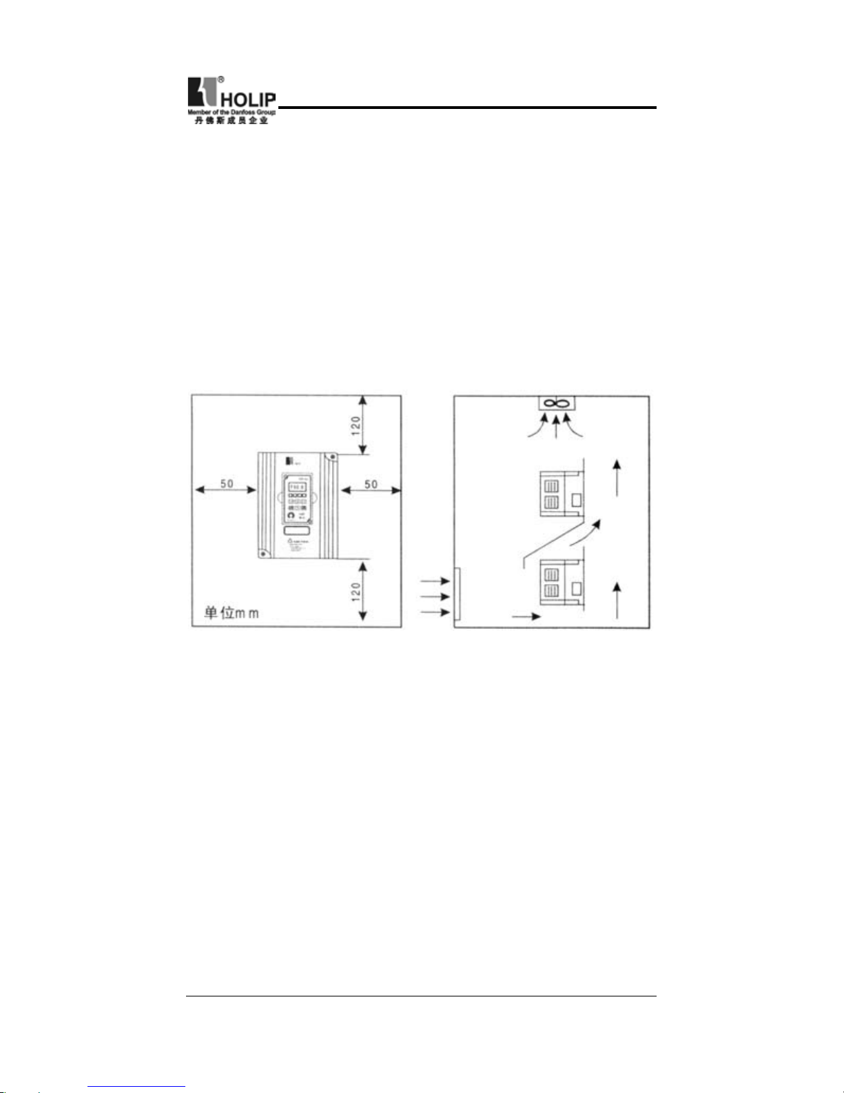
⑶ Installation Space and Direction
● There must be enough space left around the inverter for easy
maintenance and cooling. See Diagram 1.
Page 15
- 11 -
HLP-C
+
Inverters
● The inverter must be installed vertically and to ensure the
smooth ventilation for effective cooling.
;
● If there is any instability when installing the inverter, please
put a f lat board under the inverter bottom base and install
again. If the inverter is installed on a loose surface, stress may
cause damage in main circuit so as to damage the inverter.
● The inverter should be installed on non-combustible materials,
such as iron plates.
● If several inverters are installed together in one cabinet, please
add heat dissipation plates and leave enough space between
the inverters. See Diagram.
Page 16
- 12 -
HLP-C
+
Inverters
V. Wiring
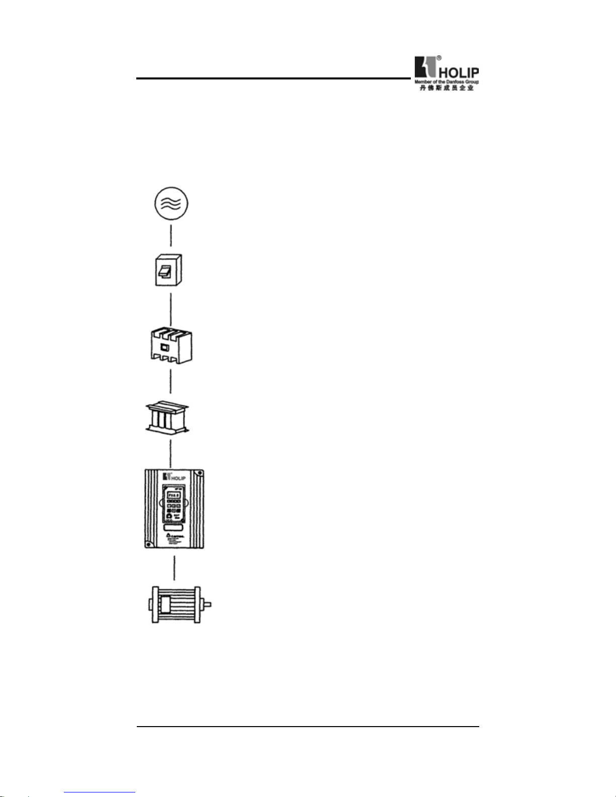
⑴ Main Circuit Schematic Diagram
Power supply:
Verify that the inverter’s rated
voltage coincides with AC power supply voltage
to avoid a damage of the inverter.
No fuse breaker:
Refer to the related list.
Ground fault circuit interrupter
:
Use one of anti-high harmonic.
Magnetic contactor:
Note:
Do not use the magnetic contactor as the
power supply on/off button for the inverter.
AC reactor:
It is recommended to install a AC
reactor for power factor improvement if the
intput capacity is more than 1000KVA.
Inverter:
● Be sure to make correct connections of the
main circuit wires and control signal wires of
the inverter.
● Be sure to make correct setting of parameters
for the inverter.
Page 17
- 13 -
HLP-C
+
Inverters
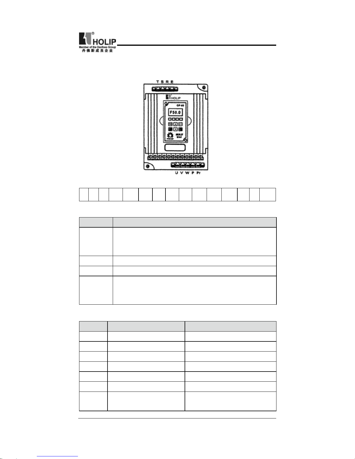
⑵ Function Description of Circuit Terminals
1. Main Circuit Terminals Arrangement
2. Control Circuit Terminals Arrangement
FA FB FC DRV FOR REV RST SPL SPM SPH GND AM VI AI +10V
3. Function description of main circuit terminals
4、Function description of control circuit terminals
Symbol Function Description
R.S.T
Input terminals of AC line power.(230V class, for
both single/three phase, single phase connected to
any two phases)
U.V.W Output terminals to motor.
P.P.r External braking resistor terminals.
E
Ground terminals: the third kind of grounding for
230V and special grounding for 400 V of Electrical
Engineering Regulations.
Symbol Function Description Factory setting
FOR Multi-function input 1 Forward run
REV Multi-function input 2 Reverse run
RST Multi-function input 3 Reset
SPH Multi-function input 4 High speed
SPM Multi-function input 5 Intermediate Speed
SPL Multi-function input 6 Low Speed
GND
Common end for digit
control signals
Page 18
- 14 -
HLP-C
+
Inverters
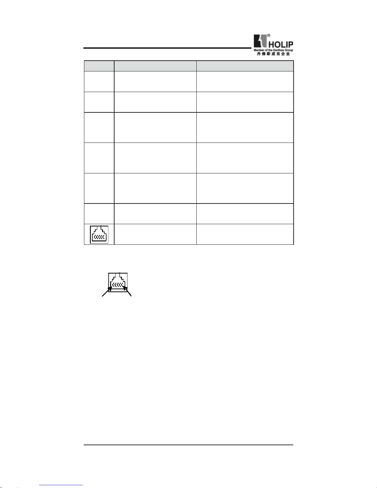
Mark: The pin denitions of RS485 communication interface
are as follows:
Pin1 Pin6
Pin1:GND; Pin2:+5V; Pin3:RS+;
Pin4:RS-; Pin5:GND; Pin6:GND
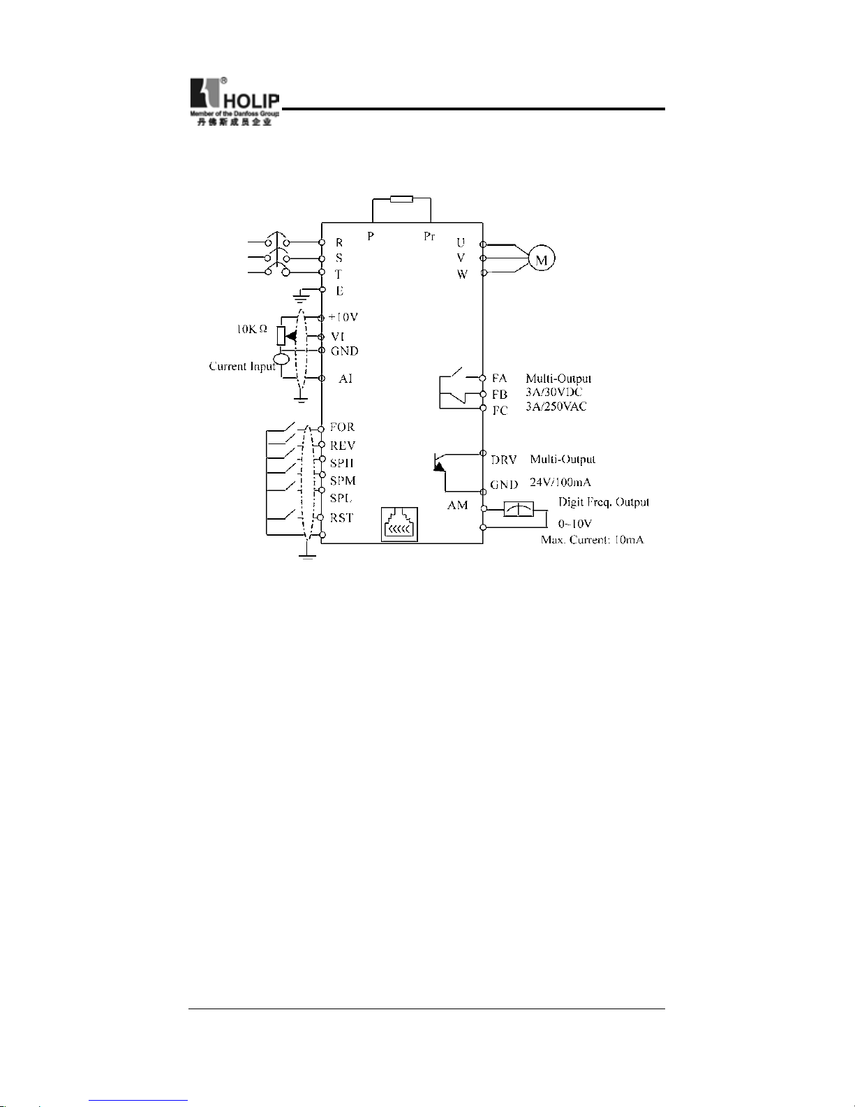
⑶ Basic Wiring Diagram
The whole wiring of the inverter is divided into two parts,
main circuit terminal connections and control circuit terminal
connections. Users can see the main circuit terminals, and the
control circuit terminals after removing the outer cover. The
terminals must be connected correctly as the following wiring
circuit diagrams.
Symbol Function Description Factory setting
+10
Power supply for analog
freqency
+10V
VI
A n a l o g f r e q u e n c y
reference input (voltage)
0~+10V corresponding to the
highest operating frequency
AI
A n a l o g f r e q u e n c y
reference input (current)
4 ~20 m A co r r e s p o n d i n g
to t he h i g he s t op e rat i ng
frequency
DRV
Mu lti-function out put
terminal (Optical couple
output)
DC24V/100mA
FA
FB
FC
Mu lti-function out put
terminal 3 (N/O or N/C)
3A/250VAC3A/30VDC
AM
D i g i t a l f r e q u e n c y
outputtermina
0-10V
RS485 communication
interface
Page 19
- 15 -
HLP-C
+
Inverters
The following diagram shows the factory standard connection of
Model HLP-C+
(4) Precautions on Wiring
a:For main circuit wiring:
● While wiring the sizes and specications of wires should be
selected and the wiring should be executed according to the
electrical engineering regulations to ensure the safety.
● It is better to use shield wire or wire and tube for power cord
and ground the shield layer or two ends of wire tube.
● Be sure to install a No Fuse Breaker (NFB) between the power
supply and the input terminals (R.S.T). (If using ground fault
circuit interrupter, please choose the one cor responding to
high frequency)
● The power line and the cont rol line should be arranged
separately and should not be laid in the same ducts..
● Never connect AC power to the output terminals (U.V.W) of
the inverter.
● Output wires mustn’t be in touch of the metal part of the outer
cover, or it will cause earth short-circuit.
● Phase-shifting capacitor, LC, RC noise lters, etc, can never
Page 20
- 16 -
HLP-C
+
Inverters
Model
HLPC+00
D423B
HLPC+0
D7523B
HLPC+0
1D523B
HLPC+0
2D223B
HLPC+0
D7543B
HLPC+0
1D543B
HLPC+0
2D243B
NFB
Capacity
16A 16A 32A 32A 16A 16A 16A
Wire
Size
2.5mm² 2.5mm² 2.5mm² 4mm² 2.5mm² 2.5mm² 2.5mm²
Screw M4 M4 M4 M4 M4 M4 M4
Note: The parameters above are only for reference, not a standard.
be connected between the motor and the output terminals
(U.V.W) of the inverter.
● The main circuit wire must be enough far away from other
control equipments.
● When the wiring between the inverter and the motor exceeds
15 meters for 230V class or 30 meters for 440V class, much
higher dV/dT will be produced inside the coil of motor, which
will cause the destroy to the interlayor insulation of motor.
Please change it to a special AC motor for the inverter or add a
reactor on the side of the inverter.
● Please lower the carrier frequency if there is longer distance
betweent the inerter and the motor. Because the higher carrier
frequency will result in the bigger leakage current of highorder harmonics of the cables the leakage current will have
unfavorable effect on the inverter and other equipment.
Specications for NFB and Wire
b:For control circuit wiring (signal line)
● The signal line should be separately laid in a different duct
with the main circuit wire to avoid any possible interference.
● Please use the shielded cable with the size of 0.5-2mm2 for
signal lines and make one end grounding. while the shielded
cable with the size of 1 mm² is recommended for the control
line.
● Use the control terminals correctly according to your needs.
c:Grounding
● Ground i ng t er m i nal : T he t h i rd g rounding me t hod
E
Page 21

- 17 -
HLP-C
+
Inverters
⑴ Good ⑵ Good ⑶ Not good
(Grounding resistance should be 100. or lower.)
● Choose grounding wires according to the basic length ans
size of the technical requirements of the electric equipment.
● Do avoid shar ing grounding wire with other large power
equipment such as electric welder, dynamic machine, etc.
The grounding wire should be kept away from the power
supply wires.
● The-grounding method for several inverters together should
be done as the first and second diagrams. Avoid the third
diagram.
● The grounding wire must be as shorter as possible.
● Please make correct grounding in the earthing terminal area.
Never connect it to zero line.
Page 22

- 18 -
HLP-C
+
Inverters
VI. Description of Digital Operator
⑴ Description of Digital Operator
⑵ Display Status
1
.During stopping: STOP on.
2.
During operation
a: In case of output, RUN on, STOP dark; in case of forward
rotating, FWD on, in case of reverse rotatying, REV on.
b:Run→Stop, then RUN on, STOP ashing→RUN dark, STOP
on.
c:Forward→Reverse, then FW D on, R EV flashing→FWD
ashing, REV on.
d:When the inverter is operated in 0.00HZ, RUN ashing and
STOP off.
e:In jogging, RUN on, STOP ashing.
Page 23
- 19 -
HLP-C
+
Inverters
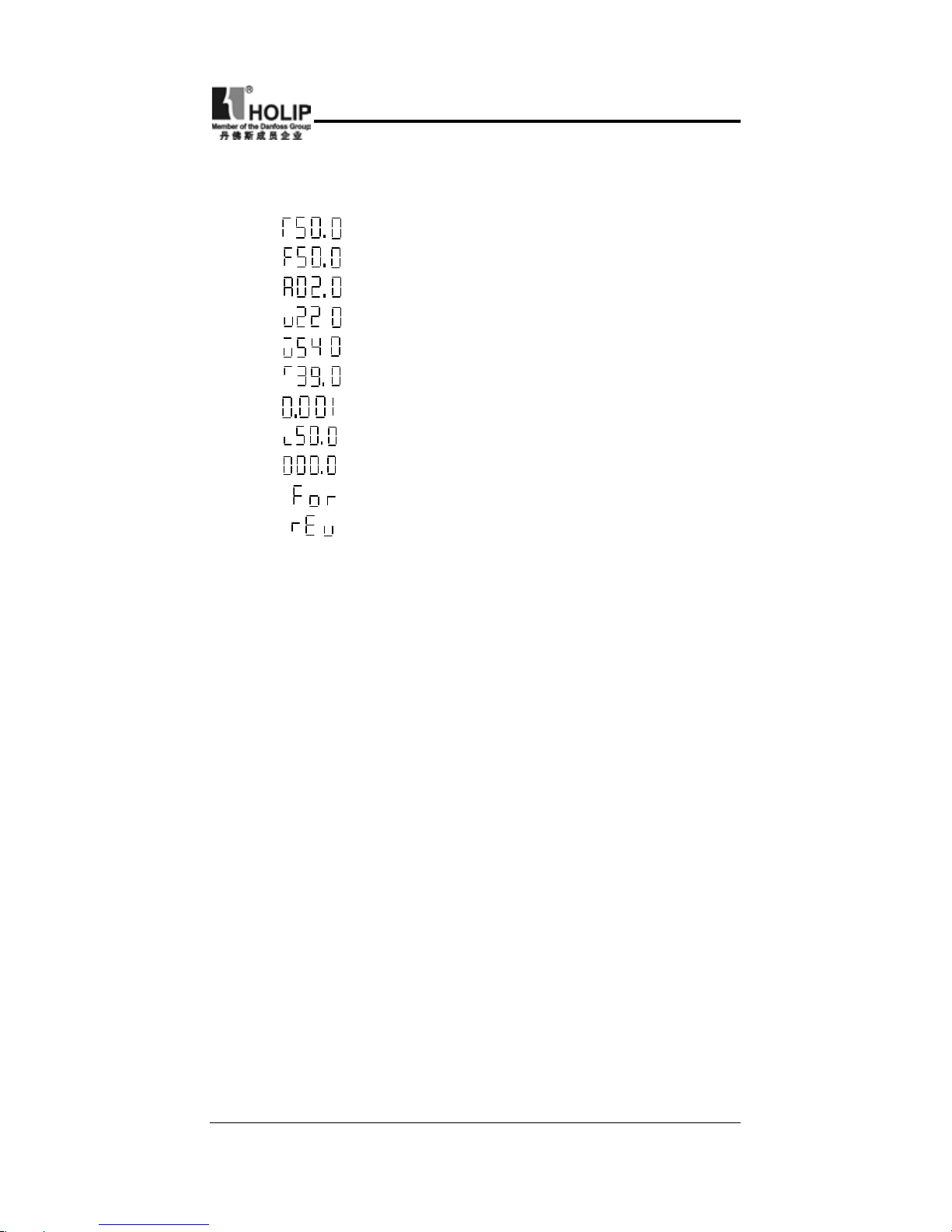
⑶ Operation instruction
A. Description: Displaying Contents
1、
Output Frequency 50.0Hz
2、
Set Frequency 50.0Hz
3、
Output Current 2.0A
4、
Output Voltage 220V
5、
DC Voltage 540V
6、
Temperature 39
℃
7、
Counter
8、
PID feedback is 50%
9、
Revolution
10、
Forward Moving
11、
Reverse Moving
B. DC voltage, the temperature, counter, PID feedback and
revolution can only be displayed af ter set ting. For specific
parameter refer to C121.
C. Show the interface content before power off at power on
D. Under the status of FOR, REV, CXXX and parameter content,
it can automatically ret u r n to the i nterfaces of f requency,
voltage, electric current, etc. automatically after several seconds.
E. Under the status of Running and Stopping, it continues to
display the original interface. But the corresponding contents
will change with the running situation and the indicator lamp
will indicate the corresponding status. During the operation the
fan is running and when stopping the fan stops running.
Page 24
- 20 -
HLP-C
+
Inverters
VII. Commissioning
(1) Important Checks Before the Commissioning
● If there is any wrong connected wires? Pay special attention to
the terminals: U.V.W; Make sure the power supply wires are
connected to R.S.T, not U.V.W.
● If there is any metal powder or other wires left on the base
plate of the inverter or at the terminals, which might cause
short circuit.
● If the scews are tightly locked and if the connecting parts are
loose.
● If there is any short circuit or earth fault in the output parts.
(2)Commissioning Methods
The procedure of the operator is factory set up for the control
method of HLP series. The commissioning can be carried out
through the digital operator. Generally, the commissioning can
be conducted at 5.00 Hz.
Procedures Display Indicator Lamp
POWER ON F000 FOR、STOP on
Press 00.00 FOR、STOP on
Press 05.00 FOR、STOP on
Press RUN F05.0 FOR、RUN on. The fan operates.
Press STOP F05.0 FOR、STOP on. The fan stops.
Note: The fan runs whe n the i nver ter is ope r ating or the
temperature is reached within the inverter. In the process the
inverter shuts down with the operation frequency dropping to
0.00HZ, STOP indicator lamp glimmer and will be on when the
inverter stops.
Page 25
- 21 -
HLP-C
+
Inverters
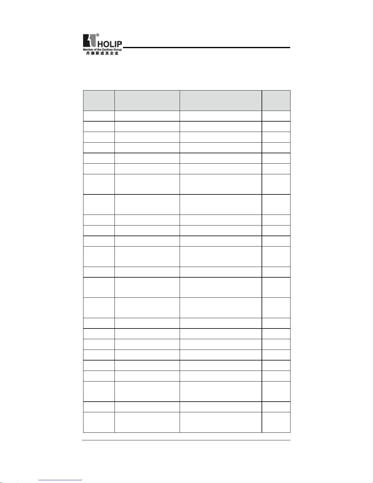
VIII. Function List
Parameter and Function List (Part 1)
Function
code
Function
Set Range & Function
Explanation
Factory
Setting
C000 Main frequency 0.0~600.0Hz 0.00
C001 Accel. Time 0.1~6500S 5.0
C002 Decel. Time 0.1~6500S 5.0
C003 V/F Curve 0~16 00
C004 Max. voltage 0.1~255/510 220/380
C005 Base frequency 0.01~600 50/60
C006
Intermediate
voltage
0.1~255/510 *
C007
Intermediate
frequency
0.01~600 *
C008 Min. voltage 0.1~* *
C009 Min. frequency 0.1~20.0Hz *
C010 Max. frequency 10.0~600.0 50.00
C011
Frequency lowe r
limit
0.0~600 0.00
C012 Running control 0~2 0
C013
Running frequency
select
0~2 0
C014
Starting mode
select
0~1 0
C015 Stopping mode 0~1 0
C016 FOR/REV select 0~1 1
C017 STOP key select 0~1 1
C018 S-Curve Time 0~6500S 0
C019 Carrier frequency 0~15 09
C020 Starting Frequency 0.1~10 1.5
C021
Stopping
Frequency
0.1~10 1.5
C022 Jog Frequency 0~600 5.0
C023
Jog Accel/Decel
Time
0.1~25.0 1.0
Page 26
- 22 -
HLP-C
+
Inverters
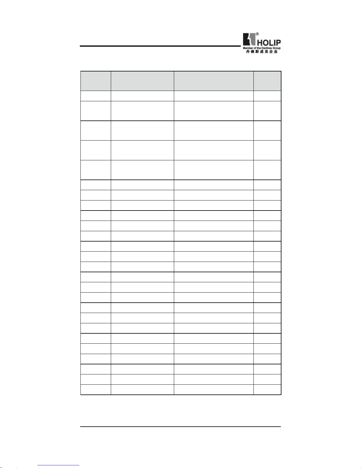
Parameter and Function List (Part 2)
Function
code
Function
Set Range & Function
Explanation
Factory
Setting
C024 PLC operation 0~5 0
C025
Auto PLC
operation
0~3 0
C026
PLC rotation
Direction
0~255 0
C027
PLC Accel/Decel
Time 1
0~255 0
C028
PLC Accel/Decel
Time 2
0~255 0
C029 Accel. Time 2 0.1~6500S 10.0
C030 Decel. Time 2 0.1~6500S 10.0
C031 Accel. Time 3 0.1~6500S 50.0
C032 Decel. Time 3 0.1~6500S 50.0
C033 Accel. Time 4 0.1~6500S 100.0
C034 Decel. Time 4 0.1~6500S 100.0
C035 Frequency 2 0.0~600.0Hz 15.0
C036 Frequency 3 0.0~600.0Hz 20.0
C037 Frequency 4 0.0~600.0Hz 25.0
C038 Frequency 5 0.0~600.0Hz 30.0
C039 Frequency 6 0.0~600.0Hz 35.0
C040 Frequency 7 0.0~600.0Hz 40.0
C041 Frequency 8 0.0~6500S 0.50
C042 PLC Timer 1 0.0~6500S 10.0
C043 PLC Timer 2 0.0~6500S 10.0
C044 PLC Timer 3 0.0~6500S 0.0
C045 PLC Timer 4 0.0~6500S 0.0
C046 PLC Timer 5 0.0~6500S 0.0
C047 PLC Timer 6 0.0~6500S 0.0
C048 PLC Timer 7 0.0~6500S 0.0
C049 PLC Timer 8 0.0~6500S 0.0
Page 27
- 23 -
HLP-C
+
Inverters
Parameter and Function List (Part 3)
Function
code
Function
Set Range & Function
Explanation
Factory
Setting
C050 Multi-input FOR 0: I n v a lid ; 1:Ru n ; 3:
Fo r. rotation; 4: Rev.
r o t a t i on ; 5: Sto p ; 5:
For/Rev.; 6: Jog; 7: Jog
For rotation; 8: Jog Rev
Rotation; 9: Emergency
s t o p; 10 : Re s e t ; 12 :
O ve r he a t of r a di a t or
or mot or; 13: Timer 1
start; 14: Timer 2 start;
17: Hi g h s p e e d ; 18 :
Intermediate speed; 19:
Low speed; 20: MultiSpeed 1; 21: Multi-Speed
2; 22: Multi- Speed 3;
23: Accel/Decel select 1;
24: Accel/Decel select
2; 2 5: U P f u n c t i on ;
DOWN f unc t ion; 27:
2 7: C o u n t e r p u l s e;
28: Count er reset; 29:
Drawing start; 31: Auto
PLC Reset suspend; 32:
PID valid
02
C051 Multi-input REV 03
C052 Multi-input RST 10
C053 Multi-input SPH 17
C054 Multi-input SPM 18
C055 Multi-input SPL 19
Page 28
- 24 -
HLP-C
+
Inverters
Parameter and Function List (Part 4)
Function
code
Function
Set Range & Function
Explanation
Factory
Setting
C056 Multi-output DRV 0: I nvalid; 1: Run; 2:
Fa u lt S ig n al; 3: Z e r o
Sp eed; 4: DC Bra king
i n d i c a t i o n ; 5 : S e t
Fr e q u e nc y r e a c h ; 6:
U n i f o r m Fr e q u e n c y
1 re a ch ; 7: Un i fo r m
Frequency 2 reach; 8: In
Accel.; 9: In Decel.; 10:
Inverter Overload alarm;
11: Mot o r Ov e r lo a d
alarm; 12: Overtorque
detect; 13: Undervoltage
a l a r m ; 1 4 : S i n g l e
stage end; 15: Process
end ; 16: Set Cou n t er
reach; 17: Inter mediate
C o u n t e r r e a c h ; 18 :
Externally c o nt r olled
T i m e r 1 r e a c h ; 19 :
Externally c o nt r olled
T i m e r 2 r e a c h ; 2 0
4~20mA disconnected;
2 7 : D r a w i n g r e a c h ;
28: PI D Down L i m i t
alarm; 29: PID Up Limit
alarm; 30: Fan run; 31:
Electromagnetic Relay
act; 32: Braking Resistor
act
01
C057
Multi-output
FABC
02
C058 Multi–Analog AM 0~7 0
C059 Analog output gain 0~100 100
C060 Up/down mode 0~1 0
C061 Reserved
Page 29
- 25 -
HLP-C
+
Inverters
Function
code
Function
Set Range & Function
Explanation
Factory
Setting
C062 Timer 1 time 0.0~10.0 00.0
C063 Timer 2 time 0~100 000
C064 Counter 0~9999 0
C065
Intermediate
Counter
0~9999 0
C066 Skip Frequency 1 0~600 0.0
C067 Skip Frequency 2 0~600 00.00
C068 Skip Frequency 3 0~600 0.0
C069
Skip Frequency
range
0.1~10.00 0.50
C070
Uniform Frequency 1
0.0~600 00.00
C071
Uniform Frequency 2
0.0~600 00.00
C072
Analog Quantity
Select
0~4 0
C073
Low end frequency
of analog quantity
0.0~600 00.00
C074
Bia s direction of
low end frequency
0~1 0
C075
High end frequency
of analog quantity
0.0~600 51.0
C076
Bia s direction of
high end frequency
0~1 0
C077
N e g a t i v e b i a s
reverse
0~1 0
C078
An a log Fi l t e r ing
Constant
0~50 20
C079
Over voltage stal l
prevention
0~1 1
C080
St a ll preve n tio n
level during accel.
0~200 150
C081
St a ll preve n tio n
level during
running
0~200 000
Parameter and Function List (Part 5)
Page 30
- 26 -
HLP-C
+
Inverters
Function
code
Function
Set Range & Function
Explanation
Factory
Setting
C082
St a ll preve n tio n
level during decel.
0~200 180
C083
Over torque detect
level
0~200 000
C084
Over torque detect
time
0.1~20.0 01.0
C085
Rated Motor Voltage
* 220/380
C086
Rated Motor Current
* *
C087 Motor poles 02~60 04
C088
Rated Motor
Revolution
0~9999 1440
C089
Motor no-load
current
0~100 40
C090 Slip compensation 0~1.0 0.000
C091 DC braking voltage 0.0~20.0 2.0
C092
DC braking time at
starting
0.0~25.0 0.0
C093
DC braking time at
stopping
0.0~25.0 0.0
C094 Speed search time 0.0~20.0 5.0
C095
Speed search
current level
0~200 150
C096
Restart after
instantaneous stop
0~1 0
C097
Allowable poweroff time
0.1~5.0 0.5
C098
Number of
abnormal restart
00~10 00
C099
Auto voltage
regulation function
0:Invalid 1:Effective 1
C100
Auto torgue
compensation
0.0~10.0 2.0
Parameter and Function List (Part 6)
Page 31

- 27 -
HLP-C
+
Inverters
Function
code
Function
Set Range & Function
Explanation
Factory
Setting
C101
Auto Energy
Saving
0.0~20.0 0.0
C102 PID P value 0~1000 100.0
C103 PID I value 0.0~3600 5.0
C104 PID D value 0.01~10 0.00
C105 PID target value 0.0~100 0.0
C106 PID target value 0~1 0
C107 PID up limit 0~100 100
C108 PID down limit 0~100 000
C109
Communication adresses0~250 000
C110
Baud rate of
communication
0~3 1
C111
C o m m u n i c a t i o n
agreement
0~7 0
C120 Parameter lock 0~1 0
C121 Display contents 0~255 00
C122 Inverter model * *
C123
Rated inverter voltag
e Set up by type *
C124
Rated inverter current
Set up by type *
C125 Countries 0~1 0/1
C126 Manufacture date Year:Month:Week *
C127 Serial No. * *
C128
Fault reset and clear
00~8 00
C129
Vo l t a g e u p t i m e
during Speed search
0.1~10.0 0.5
C130
Stall & decel time
during running
0.1~25.5 2.5
C131 Fault reset time 0.2~25.0 1.0
C132
Counte r memer y
for power-off
0~1 0
C133
Drawing memory
function
0~1 0
Parameter and Function List (Part 7)
Page 32

- 28 -
HLP-C
+
Inverters
C000 Main Frequency
Set Range
:
0.00~600.0Hz Unit:0.01 Factory Setting
:
0.00
C001 Accel. Time
Set Range
:
0.1~6500.0S Unit:0.1S Factory Setting
:
5.0
C002 Decel. Time
Set Range
:
0.1~6500.0S Unit:0.1S Factory Setting
:
5.0
IX. Description of Functions
In the digital operator method, the inverter will run at the setting
value of C000. During running, the running frequency can
be changed by pressing the ▲ or ▼ key. During multi-speed
running, the main frequency is the first speed step frequency.
In the external terminals method, if C013 is set to 1, i.e. the
running f requency is given by the potentiometer. The f irst
speed step is given by the potentiometer of the panel or external
potentiometer. Concrete conditions can be selectec by jump
wires of CN1.
The setting of main frequency is limited by the max. operation
frequency.
Accelerating Time means the time needed for the inver ter
f r eq u enc y fr o m 0H z t o 50Hz (S e e t1 i n t h e d i ag ra m).
Decelerating Time means time needed for inverter frequency
from 50Hz to 0Hz(See t2 in the diagram)
HLP-C+ Series inverter have 4 Accel/Decel Times. For Accel/
Decel Time 2.3.4 the different accelerating and decelerating
Page 33

- 29 -
HLP-C
+
Inverters
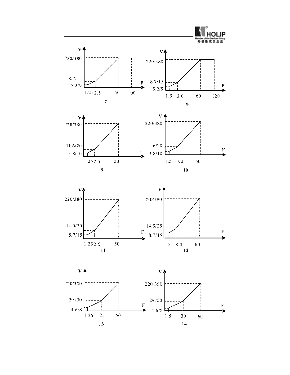
C003 V/F Curve
Set Range
:
0~16 Unit:1 Factory Setting
:
00
0:Wanton curve
1~16:16 curves are wanton and available.
When C003 is set to 0, the curve can be written wantonly by the
customer.
When C003 is set to 1~16, there are 16 curves for choice.
( ) ( )
( ) ( )
( )
( )
time can be selected through the exter nal ter minals and by
switching of Accel/Decel Time according to actual needs. In the
internal control multi-speed running, different Accel/Decel time
can be selected through simple PLC.
Page 34
- 30 -
HLP-C
+
Inverters
( )
( )
( ) ( )
( ) ( )
( ) ( )
Page 35

- 31 -
HLP-C
+
Inverters
Given values for the inverter of 230V/400V class
:
Use C003 C010 C005 C007 C009 C006 C008
Remarks
1 50 50 2.5 1.25 8.6/15 5.2/9
→
2 60 60 3.0 1.5 8.6/15 5.2/9
3 60 50 2.5 1.25 8.6/15 5.2/9
4 72 60 3.0 1.5 8.6/15 5.2/9
5 75 50 2.5 1.25 8.6/15 5.2/9
6 90 60 3.0 1.5 8.6/15 5.2/9
7 100 50 2.5 1.25 8.6/15 5.2/9
8 120 60 3.0 1.5 8.6/15 5.2/9
9 50 50 2.5 1.25 11.5/19.9 5.7/9.9
10 60 60 3.0 1.5 11.5/19.9 5.7/9.9
11 50 50 2.5 1.25 14.4/25 8.6/15
12 60 60 3.0 1.5 14.4/25 8.6/15
13 50 50 25 1.25 28.9/50 4.6/7.9
14 60 60 30 1.5 28.9/50 4.6/7.9
15 50 50 25 1.25 57.9/100 4.6/7.9
16 60 60 30 1.5 57.9/100 4.6/7.9
( )
( )
Constant Torque
Start High
Fan Model
While restor ing the factor y settings, default of Cur ve 1 or 2 is
related to the setting value of C125. When C125 is set to 0, the
factory value is restored and the default of C003 is 1, while C125
is set to 1, the factory value is restored and the default of C003 is 2.
The relevant parameters refer to the explanation of C125.
After the determination of 16 curves, C004, C005, C006, C007,
C008, C009 still can be adjusted and set. C016 is for checking the
setting.
Page 36

- 32 -
HLP-C
+
Inverters
C004 Max. Voltage
Set Range
:
0.1~255/510V Unit:0.1V Factory Setting
:
220/380
This parameter can set any intermediate voltage in the V/F
curve. If it is set improperly, it will cause motor over current or
decit torque, or even an inverter tripping.
This set value is limited by the max voltage value.
C005 Base Frequency
Set Range:0.01~600.00Hz Unit:0.1Hz Factory Setting:50.00/60.00
C006 Intermediate voltage
Set Range
:
0.1~255/510V Unit:0.1V Factory Setting
:
*
C007 Intermediate Frequency
Set Range
:
0.01~600.00Hz Unit:0.01Hz Factory Setting
:
*
This parameter can set any intermediate frequency in the V/F
curve. If it is set improperly, it will cause motor over current or
decit torque, or even an inverter tripping.
This set value is limited by the setting of base frequency.
C008 Voltage at Lower Frequency
Set Range:0.1~* Unit:0.1V Factory Setting:*
This parameter can set the lowest starting voltage in the V/F
curve.
This setti ng value is limited by t he volt age at the highest
operating frequency.
C009 Min. Frequency
Set Range:0.1~20.00Hz Unit:0.01Hz Factory Setting:*
This parameter sets the lowest starting frequency in the V/F
curve.
C010 Highest Running Frequency
Set Range:10.0~600.0Hz Unit:0.01Hz Factory Setting:
50.00/60.00
Page 37

- 33 -
HLP-C
+
Inverters
This parameter sets the highest operating frequency of the
inverter.
The settings of C006, C007, C008 and C009 are related to the
setting value of C125. When C125 is set as 0, the factory setting
is the rst V/F curve, while C125 is set as 1, the factory setting
is the second V/F curve. When restoring the factory setting the
memorized contents are as above.
Note: means uncertain values or various setting values.
C011 Frequency Lower Limit
Set Range
:
0.0~600.0 Unit:0.1Hz Factory Setting
:
0.00
This is set for preventing workers from false operation, avoiding
overheat or some other mechanical faults, which might be caused
due to the too low running frequency. When the setup frequency
is below the lower limit the inverter is running at frequency
lower limit.
This set value is limited by frequency upper limit.
C012 Control Mode
Set Range
:
0~2 Unit:1 Factory Setting
:
0
0:Control by the digital operator. The r unning command is
given through the digital operator.
1:Control by external terminals. The running command is given
through external terminals (multi-function input terminals).
2:Control by the communication ports. The running command
is given through communication ports.
C013 Running Frequency
Select Set Range
:
0~2 Unit:1 Factory Setting
:
0
0:Set by digital operator.
The running frequency is given through the digital operator.
1:Set by potentiometer.
The running f requency is controlled by the analog sig nal
through external terminals or potentiometer of the panel. Relate
to CNI state.
Page 38

- 34 -
HLP-C
+
Inverters
CN1 State
1 2 3
1 2 3
Potentiometers of the panel Analog quantities of external
terminals
2:Set by the communication ports.
The run ning frequency is given through the serial communication
ports.
C014 Starting Mode Select
Set Range
:
0~1 Unit:1 Factory Setting
:
0
Two starting modes are available for different equipment.
0:Start from the starting frequency.
When C092 is set as 0, i.e. DC brake is invalid when starting, it
starts running from its starting frequency. When C092 is set to
any non zero value, i.e. DC brake is valid when starting, it will
rst have a DC braking when starting, and then start from the
starting frequency.
Related parameters refer to C091 and C092.
1:Starting by Speed Search
This function can be used in the restarting of large inertia load.
When restarting, the inverter will trace the former speed from
the set frequency downward. In case of large inertia equipment,
when restarting, it can implement the running command right
away withourt waiting for the complete stop of the equipment by
tracking the former frequency to save time.
Note: When the inverter is restarted by speed search, it will
start tracking the frequency from its set frequency downward,
and search it at the highest speed. When starting, the current
will be high, and over current or stall may occur. Be sure to
pay attention to the adjustment of current standard position
of speed search. Generally, C095 should be set around 100%.
The concrete value should be specifically set according to the
characteristics of mechanical load.
Page 39

- 35 -
HLP-C
+
Inverters
C015 Stopping Mode
Set Range
:
0~1 Unit:1 Factory Setting
:
0
Two stopping modes a re available for the requirements of
different equipment.
0:Decelerate to stop
When C093 is set as 0, DC braking is invalid. When DC braking
is invalid, the inverter will decelerate to the stopping frequency,
and then stop toutput, and the motor will have a free running
to a nal stop. When C093 is set for any non-zero value 0, the
DC braking is valid, and the inverter will rst decelerate to the
stopping frequency, and then stop nally by DC braking.
When stopping, the DC braking is usually used in high position
stopping or for position control. Be sure to notice that frequent
uses of DC braking will cause the motor overheat.
Related parameters refer to C091 and C093.
1:Free-running Stop
W h e n t h e inver te r r eceive s a ST O P com m a nd , it wil l
immediately stop output and the motor will have a free running
till a stop. When the free-running stopping mode is selected for
the motor, DC braking is invalid.
C016 For/Rev Rotation
Select Set Range:0~1 Unit:1 Factory Setting:1
0:Reverse Run is forbidden.
1:Reverse Run is allowed.
This function is suitable for the motor, which cannot have
reverse rotation, to prevent workers from false operation. When
the reverse rotation is forbidden, the motor can only rotate
forward, and cannot have reverse rotation.
When the reverse rotation is forbidden, if switching between
For/Rev rotation on the panel, the panel will show Rev Run, but
the motor is actually making forward rotation with the indicator
lamp indicating For Run.
C017 STOP key Select
Set Range:0~1 Unit:1 Factory Setting:1
Page 40

- 36 -
HLP-C
+
Inverters
0:STOP is invalid.
1:STOP is valid.
This parameter set is only valid when C012 is set as l or 2.
When the control method is set for exte r n al terminals or
communications, the STOP key on the panel can be chosen to be
valid or not. When choosing it as valid, the STOP key can stop
the inverter in running. When it needs restarting, the for mer
running signal should be released first and then restarting is
allowable.
C018 S-Curve Time
Set Range:0~6500S Unit:1 Factory Setting:0
This parameter can be set for no impact slow start or slow stop
of the inverter when starting or stopping. When starting S-curve
the inverter will make accel or decel curve of different speed
rates according to Accel/Decel Time.
When C018 is set to 0, S-curve is invalid, i.e. accelorate or
decelorate in straight line. Without consideration of stall the
actual Accel/Decel Time is equal to the set Acel/Decel Time
plus S-curve Time.
C019 Carrier frequency (Note:0 ~ 15 corresponding to 0 ~ 16K Hz)
Set Range:0~15 Unit:01 Factory Setting:09
The carrier frequency has some affect on the electromagnetic
noise of the motor, a nd meanwhile the level of t he car r ier
frequency has certain relation with the heating capacity of the
inverter and the interference to the environment.
See the following table:
Carrier
Frequency
Electromagnetic
Noise
Heating
Capacity
Interference
to the
Environment
Low
↓
High
High
↓
Low
Small
↓
Large
Little
↓
Great
Page 41

- 37 -
HLP-C
+
Inverters
Carrier frequency corresponding table
:
Set Value 0 1 2 3 4 5 6 7 8 9 10 11 12 13 14 15
Carrier
Frequency
KHz
1.5 2 3 4 5 6 7 8 9 10 11 12 13 14 15 16
As shown in the table above, with a higher carrier frequency, the
electromagnetic noise will be lower, but the interference to other
systems must be prevented. With a lower carrier frequency, the
electromagnetic noise will be a little higher, but the heating
capacity will be small. So the carrier frequency should be set
as low as possible, especially with large power machines, if the
noice demand is not so high.
C020 Starting Frequency
Set Range
:
0.1~10.0Hz Unit:0.1Hz Factory Setting
:
1.5
Starting frequency is the initial frequency when the inverter is
started. If the starting frequency is set to 4.0Hz, the inverter will
begin to run at 4.0Hz,and later on run between 4.0 ~ 600Hz .
C021 Stopping Frequency
Set Range
:
0.1~10.0Hz Unit:0.1Hz Factory Setting
:
1.5
When the inverter receives a stop command, it will immediately
decelerate to the stopping frequency, stop output or start DC
brake to a nal stop.
If C093 is set to 0, DC brake is invalid when stopping and the
inverter will stop output.
If C093 is set to any other parameter except “0”, DC brake is
valid; the inverter will stop by DC braking.
C022 Jog Frequency
Set Range
:
0.0~600.0 Unit:0.1 Factory Setting
:
5.0
The parameter set can realize the jogging function when the
inver ter is tested. The jog operat ion can be achieved only
through the exter nal terminals, which can be set by multifunct ion input terminals. Jog frequency is limited by the
lower/upper limit of the frequency. While the jog function is
implemented, other run commands are invalid. The accelerate
Page 42

- 38 -
HLP-C
+
Inverters
time of jog frequency is set by C023. Jog stopping mode is the
same as the normal run stopping mode, which can be set by C15.
This function is only valid at stop condition. It is invalid at
running. When C012 is set to 1, it is valid.
C023 Jog Accel/Decel Time
Set Range
:
0.1~25.0 Unit:0.1 Factory Setting
:
1.0
The set value of Jog Accel/Decel Time responds to Accel/Decel
Time of 0~50Hz.
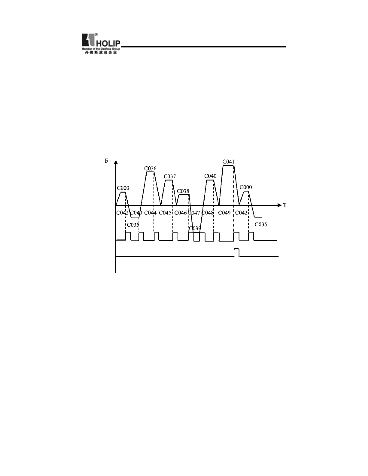
C024 PLC Operation
Set Range
:
0~5 Factory Setting
:
0
0:Normal operation, i.e. the inventer is running by the normal
control method.
1:Excternal control 4- Speed Steps
In the excternal control 4-Speed Steps the disturbance function
can be used at intermediate speed. Then C41 (Frequency 8) is
the disturbance amplitude. If it is equal to zero this function is
invalid. C042 Time 1 and C043 Time 2 are disturbance time.
Detail descriptions refer to the function description and diagram
of three terminals of high, intermediate and low speed C050
~
C055.
2:Excternal control multi- speeds
Page 43

- 39 -
HLP-C
+
Inverters
Multi-function Terminals
Results
Multi-
speed 1
Multi-
speed 2
Multi-
speed 3
OFF OFF OFF
Main frequency and frequency
ar e d e t er m ine d b y C 0 00 or
potentiometer.
ON OFF OFF
Multi-speed 1 and frequency are
determined by C035.
OFF ON OFF
Multi-speed 2 and frequency are
determined by C036.
ON ON OFF
Multi-speed 3 and frequency are
determined by C0375.
OFF OFF ON
Multi-speed 4 and frequency are
determined by C038.
ON OFF ON
Multi-speed 5 and frequency are
determined by C039.
OFF ON ON
Multi-speed 6 and frequency are
determined by C040.
ON ON ON
Multi-speed 7 and frequency are
determined by C041.
Note:
(1) To realize Excternal control 8-Speed Steps it is only valid
when Multi-input is set for Multi-speed 1, 2, 3 and C024 is set to 2.
(2) By using Multi-speed 1, 2, 3 they can make up 7- Speed
Steps. Adding the main frequency it will compose the setting of
8-Speed Steps.
(3) The frequencies of Step 1 ~ Step 7 are determined by
C035~C41.
(4) Each Acel/Decel Time is determined by the external multi-
function terminal.
(5) The directions of each program running are determined by
the external multi-function terminals.
(6) The main frequency can be given in two ways. One method
is to set it by C000 and another is to set it by the potentiometer.
When C013 is set to 1 the frequency of Main Frequency is given
by the potentiometer of the panel or external analog quantiy.
(7) The common use of Multi-speed and analog quantity is only
Page 44

- 40 -
HLP-C
+
Inverters
Note:
⑴
The frequency at each inflection point is determinded by
C000 and C035.
⑵
Skip Frequency is determined by C041.
⑶
Running Time is determined by Timer C042 and C043.
⑷
Restart after power off. The running status of frequency will
not be memorized.
4:Internal control Multi-speed
valid in the external control multi-speed. It is invalid in the
external control 4- speeds.
3: Disturbance (Traverse function)
This is a special parameter in the chemical fiber and printing
and dying industries to realize the traverse function. Except the
commands of stop, external faults and emergency stop all other
commands will not be accepted at running.
Note:
(1) Main speed and 7-speeds composes 8-speeds.
Page 45

- 41 -
HLP-C
+
Inverters
(2) Acel/Decel Time of each speed is set by PLC Acel/Decel
Time C027 and C028. Refer to the detail descriptions of C027
and C028.
(3) Running Time is set by Timer C042~C049. For the control
step not used the timer can be set to 0.
(4) Running direction of each speed is determined by C026.
(5) In the internal control multi-speed running the running
time and direction are determined by the setting of internal
parameters. Any external switch of time and For/Rev rotation is
invalid.
(6) Restart after power off. It will restart from the main speed.
The status before the power off will not be memorized.
5:Drawing
This is a special parameter for the constant speed of unwinding
and rewinding. By using this function the linare speed constance
within a certain accuracy can be realized.
Mult-input
Multi-output
Note:
(1) Through the trigger of the external multi-function terminal
the drawing action beging to be implemented.
(2) In implementation of drawing the actual running time is
T=C042×10;
(3) when the drawing is finished the inverter will have output
of C036 at the constant seed and the corresponding multi-ouput
contact will act. Until receiving the Stop command the inverter
will stop running and the multi-ouput contact will reset.
(4) In case of C133=1, it has the memory function of power
off. When it restarts after the power off the prior status will be
memorized.
(5) The output frequency for drawing can be either up or down.
Page 46

- 42 -
HLP-C
+
Inverters
C025 Auto PLC Operation
Set Range
:
0~3 Factory Setting
:
0
0:Stop after the program runs for onw week.
1:Cycling Running.
2:Stop after it runs automatically for one week(Stop for
intervention).
3:Auto r un n i ng (Stop for i ntervention)and r e c ycling
operation.
Note: This parameter set is only valid when C024 is set to 4. For
relevant parameters refer to C000, C024, C035~C049.
0:Stop after the program runs for onw week.
Whe n the command of auto program r unni ng is given the
inverter start to operate with the setting of internal parameters.
It stops automatically after running for one week. Only with
another running cammand given the inverter can restart.
1:Cycling Running.
When the running command is given t he inverte r start to
operate in sequence w ith the section speed frequency and
running time set by each internal parameter and recyclied.
During the recycling operation, except the commands of stop,
external faults and emergency stop, all other commands will not
be accepted.
2:Stop after it runs automatically for one week(Stop for
intervention
)
Note:
(1) Whhen the command of automatic program running is given
Page 47
- 43 -
HLP-C
+
Inverters
the inverter will operate according to each parameter, but it will
stop rst and then restart at the change of each stage. It will stop
automatically after running for onw week. Only with another
running cammand given the inverter can restart.
(2) The f r equencies of e ach speed step a re s et by C 0 0 0,
C035~C041.
(3) The running times of each speed step are set by C042~C049.
(4) The running direction is set by C026.
3:Auto running (Stop for intervention) and recycling operation.
Step nished
Command
Pattern nished
Command
Note:
(1) After the auto pattern run command is given the inverter will
run according to the parameters, but at every change of step it
will stop rst and then start again. It will continue and stop until
the OFF command for auto run is given.
(2) When each step is nished the corresponding multi-function
output contac will act.
(3) When each pattern run is nished the corresponding multi-
function output contac will act.
(4) The width of output pulse is 20 ms.
(5) When running again after power off all the actions will be
started from the beginning and the previous states will not be
memorized.
Page 48

- 44 -
HLP-C
+
Inverters
C026 PLC Rotation Direction
Set Range:0~255 Factory Setting:0
This parameter is only valid when C024 is set to 4.
The setting of this parameter determines the rotation directions
of each frequency step of C035~C041 and C000 in the pattern
run. The setting method is as follows:
The rotation direction is set rst in the binary bit mode, and then
converted to a decimal value for the setting of this parameter.
For instance:
bit 0-7
7 6 5 4 3 2 1 0
0 1 0 0 1 0 1 0
0:For 1:Rev
Main Speed (C000)For
Step 1 (C035) Rev
Step 2 (C036) For
Step 3 (C037) Rev
Step 4 (C038) For
Step 5 (C039) For
Step 6 (C040) Rev
Step 7 (C041) For
The parameter value 01001010 is converted to a decimal value:
1×26+1×23+1×21=64+8+2=74
Then C026=74
C027 PLC Accel. / Decel. Time 1
Set Range:0~255 Factory Setting:0
This parameter is only valid when C024 is set to 4.
Thisparameter is set to determine the accel/decel time values
of Step 1~4 of the internally controlled multi-speed. Its setting
method is as follows:
Page 49

- 45 -
HLP-C
+
Inverters
(1) Determine each accel/decel time in in the binary 2 bit mode
Bit1 Bit2 Accel/Decel Time
0 0 Accel/Decel Time 1: C001, C002
0 1 Accel/Decel Time 2: C029, C030
1 0 Accel/Decel Time3: C031, C032
1 1 Accel/Decel Time 4: C033, C034
(2) Determine the accel/decel time of each speed step in in the
binary 8 bit mode
Speed No. 4 Speed No. 3 Speed No. 2 Speed No. 1
t4 t3 t2 t1
0 1 1 0 0 0 1 1
t1 Select Accel. Time 4 t2 Select Accel. Time 1
t3 Select Accel. Time 3 t4 Select Accel. Time 2
The setting value: 1×20+1×21+1×25+1×26=99, So C027is set to 99.
Attach:20=1+21=2, 22=4, 23=8, 24=16, 25=32, 26=64
C028 PLC Accel. / Decel. Time 2
Set Range:0~255 Factory Setting:0
Thisparameter is set to determine the accel/decel time of Step
5~8 of the internally controlled multi-speed. Its setting method
is the same as C026 and C027. Details refer to the description of
C027.
C029 Accel. Time 2
Set Range:0.1~6500S Unit:0.1S Factory Setting:10.0
C030 Decel. Time 2
Set Range:0.1~6500S Unit:0.1S Factory Setting:10.0
C031 Accel. Time 3
Set Range
:
0.1~6500S Unit:0.1S Factory Setting
:
50.0
C032 Decel. Time 3
Set Range:0.1~6500S Unit:0.1S Factory Setting:50.0
Page 50

- 46 -
HLP-C
+
Inverters
C033 Accel. Time 4
Set Range:0.1~6500S Unit:0.1S Factory Setting:100.0
C034 Decel. Time 4
Set Range:0.1~6500S Unit:0.1S Factory Setting:100.0
C035 Frequency 2 Factory Setting: 15.0
C036 Frequency 3 Factory Setting: 20.0
C037 Frequency 4 Factory Setting: 25.0
C038 Frequency 5 Factory Setting: 30.0
C039 Frequency 6 Factory Setting: 35.0
C040 Frequency 7 Factory Setting: 40.0
C041 Frequency 8 Factory Setting: 0.50
Set Range:0.0~600.0Hz Unit:0.1Hz
C042 PLC Timer 1 Set Factory Setting: 10.0
C043 PLC Timer 2 Set Factory Setting: 10.0
C044 PLC Timer 3 Set Factory Setting: 0.0
C045 PLC Timer 4 Set Factory Setting: 0.0
C046 PLC Timer 5 Set Factory Setting: 0.0
C047 PLC Timer 6 Set Factory Setting: 0.0
C048 PLC Timer 7 Set Factory Setting: 0.0
C049 PLC Timer 8 Set Factory Setting: 0.0
Set Range:0.0~6500S Unit:0.1S
The related parameters refer to the descriptions of C024, C025,
C026, C027 and C028.
C050 Multi-Input FOR Factory Setting
:
02
C051 Multi-Input REV Factory Setting:03
C052 Multi-Input RST Factory Setting:10
C053 Multi-Input SPH Factory Setting:17
C054 Multi-Input SPM Factory Setting:18
C055 Multi-Input SPL Factory Setting:19
Set Range
:
00~32 Unit
:
no
00:Invalid: When the terminal is set for empty, it can avoid
faulse operation.
Page 51

- 47 -
HLP-C
+
Inverters
01:Run: It can be combined with other terminals to combine
various control methods.
02:Forward rotation
03:Reverse rotation
04:Stop
05:For/Rev switching
06:Jog07:Jog For rotation
08:Jog Rev rotation
09:Emer gency Stop: It c a n receive externally coming
emergency stop or other fault signals. When the terminal
is closed, the inverter will stop output and come to a stop
at free running.
10:Reset: This terminal can be used to reset after the fault is
removed.
12:Overheat of radiator or motor: This contact can be used
to detect overheat of the radiator or motor to protect the
motor and inverter.
13: Externally Controlled Timer 1 start: When the contact is
closed, the timer will start and begin to count time. When
the timer reaches the point the responding multi-inputs
will act.
14:Externally Controlled Timer 2 start
17:Hig h Sp eed: High, int er mediate a nd low spe ed can
compose three kinds of different operation patterns.
18:Intermediate Speed: In the three terminals the high-end
signal has priority.
19:Low Speed : Low, intermediate a n d hig h speed are
determined by Frequency 2, 3, 4.
20:Multi-speed 1
21:Multi-speed 2: Multi-speed 1, 2, 3 can compose 7-Steps.
22:Multi-speed 3
23:Acel/Decel Select 1: This terminal can be used to selcect
the acel/decel time of the inverter.
24:Acel/Decel Select 2: 4 kinds of Acel/Decel are available
for choice.
25:UP f u nction: When th i s t e r mi n al s w itch a c t s the
frequency of the inverter will increase or decrease. When
the terminal switch is hold the frequency will rapidly
Page 52

- 48 -
HLP-C
+
Inverters
increment upward or decrement downward. The up or
down speed is determined by the present accel/decel time.
The function of power-off memory can be set through
C060.
26:DOWN function
27:Counter pulse: When the terminal is set for the counter
it can receive the pulse signal of ≤250HZ and count the
time.
28:Counter reset: the action of this contact can clear the
pres e nt counting values a nd r estore C00 to r estar t
counting.
29:Drawing star t : W h e n the contact i s t r igge r e d t h e
actionofdrawing will start.
31:Auto PLC reset suspend: This contact can be used to
realize the function of suspending clear-up of Auto PLC.
A. Using the t h r e e mult i-function terminals to form the
connection method of three-wire system for the realization of
switching FOR/REV, which is extentively applied in the case of
switching For/Rev of photoelectric switches.
This function is only valid when
C012 is set to 1.
Setting:C050=02 C051=03
C052=04 C012=1
Action Description:
When triggering FOR, the inverter will rotate forward (starting);
Whentriggering REV, the inverter will rotate reversely;
When pressing STOP, the inverter will stop.
Page 53

- 49 -
HLP-C
+
Inverters
B. Use RUN, DCM, F/R to combine for Starting, Stopping and
For/Rev
:
①
Select the terminals of FOR and
REV
②
Parameter setting: C012=1 to set the
exterminal control.
C050=01 to set RUN
C051=05 to set F/R
When K2 is open it rotates forward, while K2 is closed it rotates
reversely.
C. Description of Accel/Decel Time 1 and 2 Select
⑴
It is only valid when C024 is set to 0, 1, 2. Under the
disturbance and internal control of nulti-step it is invalid.
⑵
Any two multi-function input terminals can be combined to 4
kinds of Accel/Decel for selection.
⑶
The related multi-function input terminals are set to Accel/
Decel Select 1,2.Take the terminals of SPH and SPM as example,
when the terminals of SPH C053 is set to 23 and the terminals of
SPM to 24, then the terminals of SPH and SPM should be Accel/
Decel Time 1, 2 Select.
SPH Terminal SPM Terminal Result
OFF OFF Accel/Decel Time 1
ON OFF Accel/Decel Time 2
OFF ON Accel/Decel Time 3
ON ON Accel/Decel Time 4
Page 54

- 50 -
HLP-C
+
Inverters
D. Fu nct ion description of High, inter m e d i a t e a nd low
terminals
:
RUN
SPL
Terminal
SPM
Terminal
SPH
Terminal
Result
ON OFF OFF OFF
M a i n f r eq ue nc y a n d
frequency run with the
set value of C000.
ON ON OFF OFF
Low speed and
frequency run with the
set value of C035.
ON ON/OFF ON OFF
Intermediate speed and
frequency run with the
set value of C036.
ON ON/OFF ON/OFF ON
High speed and
frequency run with the
set value of C037.
Note:
⑴
This function is only valid when C024 is set to 1, i.e.externally
controlled 4-steps.
⑵
Low, intermediate and high speed frequency are determined
by Frequency2,3, 4.
⑶
Accel/Decel time is determined by Accel/De cel select
terminals.
Page 55

- 51 -
HLP-C
+
Inverters
⑷
When all High, intermediate and low speed has signal input it
will give priority in the sequence of high, intermediate and low
speed.
Note:
⑴
When C41 is not set to 0 it has such disturbance function. Its
disturbance amplitude is determined by C41.
⑵
Its down time of disturbance is set by C43, while its up time
is set by C42.
E. Description of UP and DOWN Function
UP DOWN Result
ON OFF Frequency up
OFF ON Frequency down
ON ON No up, no down
Page 56

- 52 -
HLP-C
+
Inverters
Note:
⑴
The function of UP and DOWN is only valid when the
operation of Operator is delected for the source of the running
frequency, i.e. C013=0.
⑵
When UP is closed the inverter’s frequency will increment.
⑶
When D OWN is closed t he inver t e r’s f requ e ncy w i l l
decrement.
⑷
When both UP and DOWNare closed at the same time the
frequency will neither increase nor decrease. It is regaded as
invalid.
⑸
When the frequency reaches the max. operation frequency it
will not increase.
⑹
When the frequency reaches the min.. frequency or its lowe
limit, it will not decrease.
⑺
It has the function of memory, including the memor y for
power-off. (Setting C60=1)
⑻
When adopting the function of UP and DOWN, its up and
down speed rate is determined by the present Accel/Decel Tiem.
⑼
When keeping pressing UP or DOWN,the frequency will
increase or decrease rapidly.
⑽
The function of UP and DOWN is valid in operation. The
frequency cannot be changed during wait.
待机
F. Description of Multi-speed 1, 2 and 3 Functions
They are only valid when C024 is set to 2. Details refer to C024.
G. Description of Counter Function
t
2
t
1
Value reach
Value reset
Note:
⑴
The signal width triggered should not be lower than 2msec
Page 57

- 53 -
HLP-C
+
Inverters
C056 Multi-Output DRV Factory Setting:01
C057 Multi-Output FA, FB, FC Factory Setting
:
02
(t1、
t2≥2msec);
⑵
When the coundting value is reached the corresponding multi-
functionoutput contact will act.
⑶
This counter is reverse counter. When the counter is reset the
setting value will be displayed and then start counting.
⑷
When the counting value is reached the displayed value is 0.
It will not count againand only start counting after it reset.
⑸
It has the function of memory. When C132=1, the counting
result can be memorized for power-off.
00:Invalid. When the terminal is set for no f unction it can
prevent false action.
01:Run. The contact will act when the inverter is in running or
receives the running command signals.
02:Fault indication. The contact will act when the inverter
detects abnormal condition.
03:Zero Speed: The contact will act when the inverter output
frequency is lower than its starting frequency.
04:DC Braking ind ication: T he contact will act when t he
inverter is in DC braking condition.
05:Set Frequency reach: The contact will act when the output
frequency reaches the set frequency.
06:Uniform Frequency 1 Reach: The contact will act when the
output frequency reaches the designated frequency (C070).
07:Uniform Frequency 2 reach: The contact will act when the
output frequency reaches the designated frequency (C071).
08:In Accel: The contact will act when the inverte r is in
acceleration status.
09:In Decel: The contact will act whe n the inverter is in
deceleration status.
10:Inverter Overload alarm: The contact will act when the
inverter detects overload.
11:Motor Overload ala r m: The contact will act when the
inverter detects overloadof motor.
12: Overtorgue detect: The contact will act when the inverter
Page 58

- 54 -
HLP-C
+
Inverters
detects over torque.
13:Undervoltage alarm: The contact will act when the inverter
detects under voltage.
14:Single Step end: The contact will act and output a pulse
when the inverter nishes a single step in implementation of
pattern operation.
15:Process end: The contact will act and output a pulse when
the inver ter f i nishes all the steps in implementation of
pattern operation (i.e. after one week).
16:Set Counter reach: The contact will act when the inverter
implements the external counter and the counting value is
equal to the set value (C064).
17:Intermediate Counter reach: The contact will act when the
inverter implements the external counter and the counting
value is more than or equal to the set value (C065).
18:Externally Controlled Timer 1 reach: The contact will act
when the timer reaches the set value.
19:Externally Controlled Timer 1 reach
20:4∽20mA disconnected. When the AI input signal is opend
the contact will act.
27:Drawing Reach: The contact will act when the drawing
action is nished. The contact will automatically reset when
the inverter stops.
28:PID Lower Limit alarm: This contact will act when the PID
feedback quantity is lower than the lower limit (C108).
29:PID Upper Limit alarm: This contact will act when the PID
feedback quantity is higher than the upper limit (C107).
30:Fan run: When the inverter is working in high temperature
or in running, this contact will act.
31:Electromagnetic Relay act: When the contact pulls in the
corresponding multi-function terminal will act.
32:Braking Resistor act: When the inverter in running and the
DC voltage reaches the braking voltage the contact will act.
Page 59

- 55 -
HLP-C
+
Inverters
C058 Multi Analog AM
Set Range
:
0~7 Factory Setting
:
0
Function: Digital frequency output terminal, In combination
with C059 it can be connected to a frequency meter with the
measuring range of 10V or below for external monitoring.
0:Analog Quantity Output: Displaying output frequency, 0~10V
corresponding to 0~ Max. operation frequency.
1:Analog Quantity Output: Displaying output current, 0~10V
corresponding to 0~2 x Rated current.
2:Analog Quantity Output: Display ing out put DC voltage,
0~10V corresponding to 0~1000V.
3:Analog Qua ntity Output: Displaying output AC voltage,
0~10V corresponding to 0~510/255V.
4:Pulse Quantity Output: The corresponding relation of pulse
quantity and output frequency: 1 Pulse/Hz.
5:Pulse Quantity Output: The corresponding relation of pulse
quantity and output frequency: 2 Pulse/Hz.
6:Pulse Quantity Output: The corresponding relation of pulse
quantity and output frequency: 3 Pulse/Hz.
7:Pulse Quantity Output: The corresponding relation of pulse
quantity and output frequency: 6 Pulse/Hz.
C059 Analog AM Output Gain
Set Range
:
0~100% Factory Setting
:
100%
This parameter can be used to adjust the output voltage value
of the multi-output AM to suit frequency meter with different
measuring range and also used to correct a frequency meter. For
example, for an externally connected frequency meter with the
measuring range of 0~5V, a multi-function terminal can be used
to display its operation frequency. Then it can be corrected with
this parameter, Setting C059=50 will do.
*Note: When selecting a frequency meter please select one with
measuring range below 0~10V.
Page 60

- 56 -
HLP-C
+
Inverters
C060 Up-down Mode
Set Range
:
0~1 Unit:1 Factory Setting
:
0
0:Not memorized
1:Memorized
Through the setting of this parameter whether the value changed
by UP-DOWN will be memorized after stopping can be selected.
When C060 is set to 1, if restarting after stopping, the value at
stopping will be memorized. If restarting after power off, the
values at power off will not be memorized, but the value set by
C000 will be memorized. When C060 is set to 0, if restarting
after stopping, it will retur n to the value of C000, the value
changed by up-down will not be memorized..
C062 Timer 1 Time
Set Range
:
0.0~10.0 Unit:1 Factory Setting
:
0
C063 Timer 2 Time
Set Range
:
0~100 Unit:1 Factory Setting
:
0
Timer 1 is a timer of 0~10.0S and Timer 2 is a timer of 0~100S.
When the timer for multi-input terminal is opened or closed
the timer starts to count time. When the set time is reached the
corresponding multi-output contact will act. When the timer
cut off open the timer for multi-output will reach to reset time.
During running, if the machine stops due to fault, the timer will
count time normally and not suspend; if the machine stops due
to power off, the timer will reset automatically.
he counter can be regarded as the trigger by many function
outside end sons, when counter value reaches establishing value
C064, corresponding many function output contact movement,
after putting by counter, counter put the location, count and
resume, touching off the signal can be utilized and close to the
switch , photoelectric switch ,etc..
Page 61
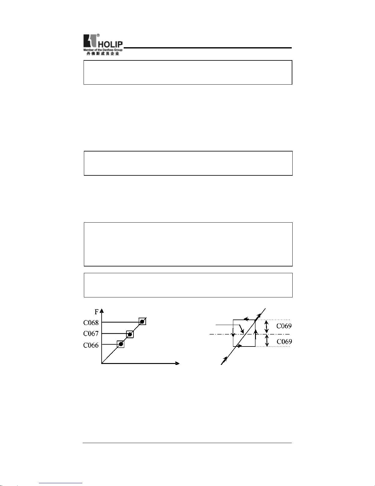
- 57 -
HLP-C
+
Inverters
C064 Counter
Set Range
:
0~9999 Unit:1 Factory Setting
:
0
An external terminal of multi-function can be used as a trigger
for the counter. When the counter reaches set value C064 the
corresponding multi-function output contact will act. After
the counter is reset and returns it will start counting again. A
proximity switch or optoelectronic switch can be used for the
trigger signals.
C065 Intermediate Counter
Set Range
:
0~9999 Unit:1 Factory Setting
:
0
Intermediate Counting Value is one value of counting range.
When the counter reachesthis value the corresponding multifunction output contact will act and output one pulse signal. It is
valid when the set value of C065 is smaller than C064.
C066 Skip Frequency 1
C067 Skip Frequency 2
C068 Skip Frequency 3
Set Range
:
0.00~600.00Hz Unit:0.1Hz Factory Setting
:
0.0
C069 Skip Frequency Range
Set Range
:
0.1~10.00Hz Unit:0.1Hz Factory Setting
:
0.5
Frequency
To avoid a mechanical resonance point three frequency hop
points are set. In case of C069=0, all hopping frequencies are
invalid. The actual hopping frequency range is two times that of
C069, as shown in the above diagram.
Page 62
- 58 -
HLP-C
+
Inverters
C070 Uniform Frequency 1 Set
C071 Uniform Frequency 2 Set
Set Range
:
0.00~600 Unit:0.1Hz Factory Setting
:
0.0
When the output frequency reaches the set values of C070, C071
the corresponding multi-function output contact will act.
C072 Analog Quantity Select
Set Range
:
0~4 Factory Setting
:
0
0
:
0~10V 1
:
0~5V 2
:
0~20mA
3:4~20mA 4:0~10V and 4~20mA stacked
This parameter can be set to satisfy different analog input
signals.
When C072=4, output frequency =(U/Umax + I/Imax)*50Hz/2
Among which: U:Analog Quantity Voltage Quantity; Umax:
Maximu m A n alog Quantit y Voltage Q u a ntity; I: A n alog
Quantity Current Quantity; Imax: Maximum Analog Quantity
Current Quantity.
For example, When +10V and 20mA are repectively entered for
the analog quantity, the output frequency of the inverter is 50Hz.
(In case the max. operation frequency is set to 50Hz)
C073 Analog Quantity Low End Frequency
Set Range
:
0.0~600.0Hz Unit:0.1Hz Factory Setting
:
0.0
074 Bias Direction of Low End Frequency
Set Range
:
0~1 Factory Setting
:
0
0:Forward dirction
1:Reverse direction
C075 Analog Quantity High End Frequency
Set Range
:
0.0~600.0Hz Unit:0.1Hz Factory Setting
:
51.0
C076 Bias Direction of High End Frequency
Set Range
:
0~1 Factory Setting
:
0
0:Forward dirction
1:Reverse direction
Page 63

- 59 -
HLP-C
+
Inverters
Setting:C073=50
C074=1
C075=50
C076=0
C077=1N
Note: 5~10V corresp. to
0~50Hz
C073=50
C074=0
C075=0
C076=0
Note:0~10Vcorresp.50~0H
C073=10
C074=1
C075=40
C076=0
C077=1
Note:0~10V corresp.10~40Hz,
-10Hz means Rev 10Hz
C077 Negative bias Reverse of Analog Quantity
Set Range
:
0~1 Factory Setting
:
0
0:Negative bias Rev is not allowable.
1:Negative bias Rev is allowable.
The parameter group is set for the measuring range and zero
point of the external analog terminals and can be combined for
any kind of curve to control the operation of the motor.
Example
:
Rev. Area For. Area
Page 64

- 60 -
HLP-C
+
Inverters
C073=10
C074=1
C073=40
C077=0
In case of C077=0, 2V-10Vsignal is
valid; 0V-2V is invalid. Motor will
not run
C078 Analog Quantity Filtering Constant
Set Range
:
0~50 Unit:1 Factory Setting
:
20
The setting of this parameter is related to the responding speed
of analog quantity. The higher the value of C078 is set, the
slower the responding speed of analog quantity will become.
Too low setting of C078 may cause the instability of frequency
with fructuation.
C079 Overvoltage Stall Prevention Select
Set Range
:
0~1 Factory Setting
:
1
0:Overvoltage stall prevention function is invalid.
1:Overvoltage stall prevention function is valid.
When the inverter is in decelerating, due to the effect of load
inerttia, the motor will produce a return energy to the inverter
and cause the DC side voltage of the inverter increase. So when
the function of overvoltage stall prevention is set valid and the
DC voltage of the inverter becomes too high, the inverter will
stop decelerating till the DC side voltage decreases to its rated
value, then the inverter will go on to execute deceleration and
the deceleration time will be extended automatically.
* Note: When the output voltage is higher the inverter will
become abnormal or turn to protection. In such case C079 can be
set to 0 (Invalid), which is easy to cause overvoltage protection.
Page 65

- 61 -
HLP-C
+
Inverters
C080 Stall Prevention Level During Acceleration
Set Range
:
0~200% Unit:1% Factory Setting
:
150
When the inverter is in accelerating, due to over load or too short
acceleration time, the output current of the inverter will go up
quickly and exceed the rated standard level. When this happens,
the inverter will stop accelerating until the current returns under
its rated value, will the inverter go on to accelerate. When using
the speed search function the value of C080 should be lowered
properly. The greater the load initia quantity is, the smaller the
value of C080 should be set. Otherwise it is extremely easy to
cause overcurrent protection.
Stall Prev. Level
Current
Output
100% current is the rated current of the motor. W hen this
parameter is set to 0, the stall prevention function is invalid.
C081 Stall Prevention Level at Constant Speed
Set Range
:
0~200% Unit:1 Factory Setting
:
0
When the inverter is in constant running, due to load uctuation
and other reasons, the current will go up. When the current
excee ds its rated value, the inverter w ill lower t he out put
frequency. When the output current returns to its normal range
the inverter will accelerate again to its set frequency.
Page 66

- 62 -
HLP-C
+
Inverters
Stall prevention level
during running
Output
frequency
C082 Stall Prevention Level During Deceleration
Set Range
:
0~200% Unit:1 Factory Setting
:
180
100% current is the rated current of the motor. When this
parameter is set to 0, the stall prevention function is invalid.
Related introduction refer to C079.
When this parameter is set to 0, the stall prevention function is
invalid.
C083 Overtorque Detect Level
Set Range
:
0~200% Unit:1% Factory Setting
:
0
When the output current exceeds the over torque detection level
and also exceeds half of the set over torque detection time (factory
setting: 1.0s), the over torque detection will begin to indicate,
and the corresponding multi-function contact will act. When
it exceeds the set time value, the inverter will turn into selfprotection. But when this parameter is set to 0, the over torque
detection will be invalid
C084 OverTorque Detect Time
Set Range
:
0.1~20.0S Unit:0.1S Factory Setting
:
1.0
When the inverter detects that the output current has exceeded
the motor cur rent set value, the inverter begins to calculate
the over torque time. When the over torque time has exceeded
half of the over torque detection time, the corresponding multifunction output contact will act, the over torque alarm will be
produced, while the inverter will continue running. When the
over torque time has exceeded the set detection time (set by
Page 67

- 63 -
HLP-C
+
Inverters
C083), the inverter will turn into self-protection, display the
fault signal and stop output.
The related parameters see C083
.
C085 Rated Motor Voltage
It is set according to the rated voltage value of the namplate. For
230V class inverters the default is 220, while for 400 V class
inverters the default is 380V.
C086 Rated Motor Current
It is set according to the rated value of the namplate. This
parameter can be used to restrict output current of the inverter to
prevent overcurrent and protect the motor. If the current of the
motor has exceeded this value the inverter of AC motor will turn
into self-protection.
C087 Motor Poles
Set Range
:
02~60 Factory Setting
:
04
This parameter is set for the pole number of the motor according
to the namplate of the motor.
C088 Rated Motor Revolution
Set Range
:
0~9999 Factory Setting
:
1440
This should be set according to the actual revolution of the
motor. The displayed value is the same as this parameter. It can
be used as monitoring parameter, which is convenient to the
user. This parameter set value corresponds to the revolution
speed at 50Hz.
C089 Motor No-load Current
Set Range
:
0~100 Factory Setting
:
40
The setting of Motor no-load current will affect the quantity
of slip compensation. 100% current is the rated current of the
motor.
Page 68

- 64 -
HLP-C
+
Inverters
T h i s set t i ng is v a li d on l y
when C014 is set to 0. Related
introduction refer to C014.
C090 Slip Compensation
Set Range
:
0~1.0 Factory Setting
:
When the inverter drives the motor the slip will become bigger
due to the increase of load. This parameter can be set for slip
compensation to decrease the slip and make the running speed
of the motor closer to synchronous speed of revolution.
C091 DC Braking Voltage
Set Range
:
0.0~20.0% Unit:0.1% Factory Setting
:
2.0
This parameter is set for the DC brake voltage to of the motor
at starting and stopping. It can be adjusted for different brake
voltage. When adjusting the parameter it must be increased
slowly from lower values to high values until the sufcient brake
torgue is achieved.
100% voltage is the voltage at maximum frequency.
C092 DC Braking Time at Starting
Set Range
:
0.0~25.0S Unit:0.1S Factory Setting
:
0.0
This parameter is set for DC Brake at starting and giving the
lasting time of DC Brake current of the motor at starting. If it is
set to 0 it means DC brake is invalid.
DC braking before running is normally applied in the cases in
which the load is movable in the “stop” state, such as windmill
and other machines. Because of the load existing before the
inverter drives, the motor is always in a free r unning state,
with an uncertain running direction. So the DC braking can be
executed before starting the motor to prevent the inverter from
tripping.
Page 69

- 65 -
HLP-C
+
Inverters
This parameter is valid when
C015 is set to 0. The related
parameters see C015.
C093 DC Braking Time at Stopping Set
Set Range
:
0.0~25.0S Unit:0.1S Factory Setting
:
0.0
Note: When this parameter is set to non-zero value it starts DC
brake at stopping and gives the DC brake time of the motor. DC
brake at stopping is often used for a high-level stop or position
control.
C094 Speed Search Time
Set Range
:
0.0~20.0S Unit:0.1S Factory Setting
:
2.0
This parameter is set as speed search time when the inverter
restarts by the speed search method after the external errors
or temporary power off. For the starting and stopping of some
large inertia load, because of its large inertia, if restarting the
machine after its complete stop, it will waste much time. But if
the speed search function is started, it is not necessary to wait
for the machines to come to a full stop for restart. The inverter
will search the speed from high to low with the set frequency.
After searching it it will continue to accelerate to reach the set
frequency.
C095 Speed Search Current Level
Set Range
:
0~200% Unit:1% Factory Setting
:
150
When the inverter search speed this set value sould be taken as
the level for output current. When the output current is higher
than this level the inverter will suspend searching. When the
current is restored below the current level it will then execute the
speed search again.
Af ter starting the speed search please decrease properly the
speed search current level according to the actual condition
Page 70

- 66 -
HLP-C
+
Inverters
of load. Otherwise it is extremely easy to cause overcurrent
protection.
C096 Restart after Instantaneous Stop
Set Range
:
0~1 Factory Setting
:
0
0:Invalid, i.e. the inverter will not restart after an instantaneous stop.
1:Speed search Start. Refer to C094.
C097 Allowable Power-off Time
Set Range
:
0.1~5.0S Unit:0.1S Factory Setting
:
0.5
This parameter is set for the maximum allowable power off
time. If exceeding the set time the inverter will continue to stop
input after power on. To execute the restart it needs to follow
the general starting procedures.
*Attention:When using this function special attention should
be paid to the safety. During the process of instantaneous power
off and power on the inverter may restart. It is easy to produce
danger. Be careful to use this function.
C098 Number of Abnormal Restart
Set Range
:
00~10 Unit:1 Factory Setting
:
00
After the abnormal conditions (such as overcurrent, overvoltage)
happen the invrter will automatically reset and restart. If the
starting mode is set for general mode it will start according to
the general mode. If it is set for speed search start it will start in
the speed search mode. After start it will restore the set number
again if there is not any thing unusual happened within 60
seconds. If there is any error and it reaches the set number the
inverter will not have input. It can only be started after reset. If
C098 is set to 0 the inverter will not carry out the functions of
automatic reset and restart.
C099 Auto Voltage Regulation
Set Range
:
0~1 Factory Setting
:
1
0:Invalid
1:Valid
Page 71

- 67 -
HLP-C
+
Inverters
When the input poer supply is not stable and if the voltage is over
high the operation of the motot with the power of exceeding the
rated voltage will cause the temperature of the moto increasing,
the insulation damaged and the output torgue unstable. This auto
voltage regulation can automatically stablize the output voltage
within the rated voltage range of the motor under the condition
of unstable output power supply
When this function is set to invalid the output voltage will
uctuate.
C100 Auto Torgue Compensation
Set Range
:
0.1~10.0% Unit:0.S% Factory Setting
:
2.0
This parameter can be set for the auto output of extra voltage
when the inverter is running for higher torgue, which can
compensate for the insufcient torgue at lower frequency. The
torgue compensation should not be too big and it should be set
slowly from low to high according to the actual situation.
Insufficient compensation will result in the insufficient torgue
of the motor at low frequency. And over compensation will lead
to too bigger torgue, which will produce a shock to the machine
and even result in a trip of the inverter under serious situation.
C101 Auto Energy Saving
Set Range
:
0.0~20.0% Unit:1% Factory Setting
:
0
Torge Comp.
When it is set to 0 this function is invalid. When Auto energy
saving function is opened the inverter will run at the full voltage
during acceleration and deceleration. During the operationa
at constant speed the inverter can automatically calculate the
optimum voltage value according to the power of load to supply
Page 72

- 68 -
HLP-C
+
Inverters
it to the load in order to meet the the goal of energy saving.
The output voltage can be regulated automatically and it can be
decreaed by max. 30% of normal output voltage.
Attention:For the load of frequent
change or closing to full load, this
function is not applicable.
C102 PID Constant P
Set Range
:
0.0~1000% Unit:1 Factory Setting
:
100
This proportional constant is set for the error value gain. If I=0,
D=0,it is only for proportional control.
C103 PID Constant I
Set Range
:
0.1~3600 Unit:1 Factory Setting
:
5.0
The integral time (I) is set for the reaction speed for PID. The
larger the I value is the slower the reaction speed is. But if the
integral time value is set too small, it will cause vibration.
C104 PID Constant D
Set Range
:
0.01~10.0 Unit:0.01 Factory Setting
:
0
This didderential time (D) is set for the depression operation of
PID. The larger the D value is, the more obvious the depression
operation is. When D is set to 0, it means this function invalid.
C105 PID Constant Target Value
Set Range
:
0.0~100.0 Unit:0.1 Factory Setting
:
0.0
This target value can be set through external voltage signal or
the digital operator.100% target value is corresponding to the
frequency quantity at +10V.
PID closed-loop control is usually used in the process control
of no fast physical quantity changes, such as pressure control,
temperature control, etc. The feedback signal is usually taken
Page 73

- 69 -
HLP-C
+
Inverters
from temperature, or pressure transmitter, etc. When under
PID control, the feedback signal input path is the analog current
signal 4-20mA.
PID Control Block Diagram:
Target value
Feedback
Transmitter
General operating methods of PID control:
⑴
Choose the correct transmitter (with the output specication
of standard current signal 4-20mA)
⑵
Set the right target value.
⑶
If t h e ou tput d o e sn’t h a ve o s c i llat i o n , inc r e ase t h e
proportional constant (P);
⑷
If the output doesn’t have oscillation, decrease the integral
time (Ti);
⑸
If the output doesn’t have oscillation, increase the differential
time (Td).
1.Decrease the Over
Output
a:Decrease the
differential time (D)
b:Increase the
integral time (I)
2.Decrease the
oscillation
a:Decrease the
differential time (D)
b:Extend the integral
timke (P
)
Page 74

- 70 -
HLP-C
+
Inverters
PID closed-loop control is valid only when the multi-function
inputs PID are open.
C106 PID Constant Target Value
Set Range
:
0~1 Unit:1 Factory Setting
:
0
The selection of target value can be set through the selection
of the panel or external analog quantity. The external analog
quantity is 0~10V signal or control of the potentiometer.
When C106=0,the target value of PID is set by C105.
When C106=1,the target value of PID is set by external analog
signal 0-10V(corresponding 0 -100%), the setting of C105 is
invalid.
It should be noticed that in using PID control PID is only valid
when C013 is set to 0.
C107 PID Upper Limit
Set Range
:
0~100% Unit:1 Factory Setting
:
100%
When PID feedback value is more than the set value of C107 the
corresponding multi-output terminal will act and the machine
will not stop.
C108 PID Lower Limit
Set Range
:
0~100% Unit:1 Factory Setting
:
0
When PID feedback value is less than the set value of C108 the
corresponding multi-output terminal will act and the machine
will not stop.
C109 Communication Addresses
Set Range
:
00~250 Unit:1 Factory Setting
:
00
When the inverter is set t o have R S- 485 Com munication
int erface c ontrol, each of the inverter s w ill be set for its
individual identication number through C109.
00:No communication function
01~250:Individual identication number for the inverters
Page 75
- 71 -
HLP-C
+
Inverters
Byte 0 1 2 3 4 5 6 7
ASCII Code
30H 31H 32H 33H 34H 35H 36H 37H
Byte 8 9 A B C D E F
ASCII Code
38H 39H 41H 42H 43H 44H 45H 46H
C110 Communication Baud Rate
Set Range
:
0~3 Unit:1 Factory Setting
:
1
0:4800 b/s 1:9600 b/s
2:19200 b/s 3:34800 b/s
C111 Communication Data Method
Set Range
:
0~7 Unit:1 Factory Setting
:
1
0:8N1 FOR ASCII 1:8E1 FOR ASCII
2:8O1 FOR ASCII 3:8N1 FOR RTU
4:8E1 FOR RTU 5:8O1 FOR RTU
HLP MODBUS Communication Protocol
When using the RS485 communication interface, each of the
inverters must set its own address so that the computer can use
this individual address to carry out the control.
1:Communication port terminal setting
The communication protocol
has two modes: RS485Communication Port
⑴ RTU mode (Remote Terminal Unit)
⑵ASCII mode(American Standand Code for imformation
interchange
)
Information of code.
RT U mode: E a ch of 8-bit data is c omposed of t wo 4 -bit
(hexadecimal), for example: 64H
ASCII mode: Each of 8-bit data is composed of two ASCⅡbyte,
for example:
One 1-bit data 64H (hexadecimal) is composed of ASCⅡbyte
“64”, included“6”(36H) and “4”(34H).
Page 76

- 72 -
HLP-C
+
Inverters
2:Communication Data Method
Start bit
Start bit
Bit string
Charator frame
Start bit
Bit string
Charator frame
Start bit
Bit string
Charator frame
Start bit
Bit string
Charator frame
Start bit
Bit string
Charator frame
Bit string
Charator frame
Page 77

- 73 -
HLP-C
+
Inverters
STX
“:”
(3AH)
ADDR FUNC LEN
DATA
(n-1)
....
DATA
0
CRC
END
CR(0DH)
LF(0AH)
3:Communication Document Formats
3.1 ASCII Mode
Communication Document Forms
⑴
STX:Starting unit“:”(3AH
)
⑵
ADDR communication address,8-bit data is composed of two
ASCⅡ byte.
00:Broadcast mode is MODBUS
01~250:the addresses of corresponding inverters.
⑶
FUNC:Function code 8-bit data is composed of two ASC Ⅱ
byte.
01:FUNC READ, Read the data of function code
02:FUNC WRIT, write the data of function code
03:write control data
04:read control status data
05:write inverter frequency data
06:Reserved
07:Reserved
08:Loop test
a:Read function code data
format:
ADDR 01 LEN FUNC Data
ADDR=0 means no answer
ADDR≠0 means a reply from inverter of this address
When inverter reply normal, the format as follows
:
ADDR 01 LEN FUNC Data
If DATA is one word, the LEN=3, If DATA is one byte, the
LEN=2 .
When inverter has no this function code or reply no effect, the
format as follows
:
ADDR 81H 01 FUNC
b:Write function code data
Format
:
ADDR 02 LEN FUNC Data
Page 78

- 74 -
HLP-C
+
Inverters
7 6 5 4 3 2 1 0
jogr jogf jog r/f stop rev for run
ADDR=0 for broadcast, it write to all inverter, but no reply.
ADDR≠0, set data and reply from inverter of this address.
When inverter has no this function code or reply of no effect, the
format as follows
:
ADDR 81H 01 FUNC
c:Control commands
Format
:
ADDR 03 LEN CNTR
ADDR=0 for broadcast, it write to all inverter, but no reply
ADDR≠0, reply and return.
CNTR
When the setting is correct return to present control status.
Format:ADDR 03 LEN CNST
CNST
7 6 5 4 3 2 1 0
Search
start
Braking r/f joging running r/f jog run
When check is not correct,
ADDR 83H 01 CNST
d:Read status value
Format
:
ADDR 04 01 CFG
ADDR=0, no reply
ADDR≠0, reply.
CFG=0~7, reply single data
0:Set F 1:Out F 2:Out A 3:RoTT
4:DCV 5:ACV 6:Cout 7:Tmp
For example: read set frequency
Send:01 04 03 00 41 89
Return:01 04 03 13 88 89 A6 2D
13 88 are data
13 is high order, 88 is low order.
⑷
LEN:data length, It means the length of D(n-1)…D0,
长
Page 79

- 75 -
HLP-C
+
Inverters
Quiet ADDR FUNC LEN D
(n-1)~D(0)
CRC Quiet
>50ms >50ms
Length set: when one word, LEN=3,when one byte or <1byte,
LEN=2
。
⑸
DATA:<Data characters> data content. 2n ASCII compose
n bytes, it have fty ASCⅡ at most.
⑹
LRC:longitudinal redundancy check
ASCII mode: Get LRC methods is that add ADDR to the last
data, if the result is more than 256,then the result subtract 256
until the result is less then 256 (if the result is 128H, take 28H),
then 100H subtract the result get LRC.
⑺
For example: write 30.00Hz to inverter of 01(write to C000
)
STX ADDR FUNC LEN DATA LRC END
“:”
“0”
“1”
“0”
“2”
“0”
“2”
“0”“0”“0”
“B”“HB”“8”
“3”
“7”
“CR”
“LF”
3AH
30H
31H
30H
32H
30H
33H
30H 30H 30H
42H 42H 38H
33H
37H
0DH
0AH
Calculate LRC: 01H+02H+03H+00H+0BH+B8H=C9H
C9H subtracted from 100H: 37H
So the sent data is following:3AH 30H 31H 30H 32H 30H 33H
30H 30H 30H
42H 42H 38H 33H 37H 0DH 0AH
3.2 RTU Mode
⑴
Quiet: the time of no data is more than 50 ms
⑵
ADDR:Communication address, 8-bit data
⑶
FUNC:Function code, 8-bit data, refers to 3.1-3
⑷
LEN:Data length, the length of D(n-1)~D0
⑸
DATA:data content, n*8-bit
⑹
LRC:Longitudinal Redundancy Check
RTU mode: get CRC(cyclical Redundancy Check).
The CRC calculation method is following:
⑴
make a 16 -bit register and set value 0FFFFH(call CRC
register)
⑵
done rst byte of data Exclusive OR with low byte of 16-bit
Page 80

- 76 -
HLP-C
+
Inverters
CRC register and save the result to CRC register
⑶
done 1 bit right shift with CRC register and ll zero to left
bit, then check low bit of CRC register.
⑷
if the low bit is zero, then do repeat setp3, else CRC register
do Exclusive OR with 0A001H.
⑸
done repeat step 3 and 4,until CRC register done right shift 8
times,then the byte is fully done.
⑹
done repeat step 2 to 5 for the next byte of data, until process
completely all data. The last data of CRC register is CRC value.
When send CRC value in command data, low bytes must change
the sequence with high bytes, i.e. low bytes will be sent rst.
⑺
for example 1: Write 30.00Hz to inverter of 01
Command data
ADDR FUNC LEN DATA CRC
01H 02H 03H 00H 0BH B8H 7FH 0CH
Sent data:01H 02H 03H 00H 0BH B8H 7FH 0CH
⑻
for example 2:
The following is that get CRC value with C language. The
function has two parameters:
Unsigned char data ← the point of data buffer
Unsigned char lengh ← number of data buffer
This function will send back the CRC value with unsigned
integer format.
unsigned int crc_chk(unsigned char data,unsigned char
lengh)
{
int j;
unsigned int reg_crc=0xffff;
while (lengh--){
reg_crc^=*data=++;
for(j=0;j<8;j++={
if(reg_crc&0×01){/*LSB(b0)=1*/
reg_crc=(reg_crc>>1)^0xa001;
}else{
reg_crc=reg_crc>>1;
Page 81

- 77 -
HLP-C
+
Inverters
}
}
}
return reg_crc;
}
C120 Parameter lock
Set Range
:
0~1 Unit:1 Factory Setting
:
0
0:Invalid. The parameter can be set.
1:Valid, i.e. parameter lock. Except this parameter and C000
other parameterscan bechanged.
This parameter can be used to prevent any wrong setting of
other values by non maitenance persons.
C121 Display Contents
Set Range
:
0~255 Factory Setting
:
00
DC Voltage: 1
Temperature: 2
Counter: 4
Feedback Value: 8
RPM: 16
Normally we can see directly output frequency, set frequency,
output cu r rent,output voltage, but temperat ue, DC voltage,
count er, PID feedb a ck a nd revolution s peed can o n ly be
monitored and displayed in sequence through switching keys
after the setting of C121.
Set the corresponding code for C121. If it often displays the
content of more than tow items set the corresponding code for
C121 again.
For example: when asking for displaying the temperature and
revolution, then C121=2+16=18,just set C121to 18.
C122 Inverter Model Factory Setting:*
Factory Setting. It can be monitored, but not set.
C123 Rated Inverter Voltage Factory Setting:*
Factory Setting. Depending on the model. It can be monitored, but not set.
Page 82

- 78 -
HLP-C
+
Inverters
C124 Rated Inverter Current Factory Setting:*
Factory Setting. Depending on the model. It cann’t be changed.
It can be monitored, but not set.
C125 Country 50/60Hz
Set Range
:
0~1 Factory Setting
:
0
0:50Hz
1:60Hz
Specic setting according to the grid.
C126 Inverter manufacture date
Factory Setting:****
Factor y Setting. It can be
monitored, but not set.
Week
Month
Year
C127 Manufacture Serial No.
Factory Setting:*
Factory Setting. It can be monitored, but not set.
Through the manufacture serial number the manufavtury date,
nymber as well as the information aobut the inverter such as
the numbers of main circuit board and base plate, etc. can be
checked.
C128 Parameter Reset, Fault and Clear-up
Set Range:0~12
Unit
:1
Factory Setting
:0
0:Software Version No. 1~4:Fault record
6:Fault clear up 8:Restore factory settings
10:Input frequency at fault 11:Input current at fault
12:Bus voltage at fault
Through C128 the software version no., fault record can be
checked. In case of no fault record Display 1 will appear. Enter
into the parameter and set it to 0~4 so as to check fault record.
Through the setting of C128 the fault record can be cleared
Page 83

- 79 -
HLP-C
+
Inverters
up and the factory If the value has not been set properly due
to some reasons or the value is abnormal it can be set to 08 to
restore the factory setting and then reset again.
Items 0~4: They can be monitored, but not set.
C129 Voltage Up Time during Speed Search
Set Range
:
0.1~10.0S Unit
:
0.1
Unit:0.5
When the starting method of the inverter is set to speed search
there is a process of voltage increase during the speed search.
Whhen the voltage is increae rapidly the current will be high
and the searching process will be fast. When the voltage is up
slowly the current will be low and the searching process will be
slow. Generally the value is set less for the machine with smallr
power and set more r the machine with larger power.
C130 Stall & Decel Time during Running
Set Range
:
0.1~25.5S Unit:0.1 Factory Setting
:
2.5
Set the speed of frequency decrease for stall prevention at
constant speed.
C131 Fault Reset Time
Set Range
:
0.2~25.0S Unit:0.1 Factory Setting
:
1.0
When the inverter is set to fault restart and if theinverter has
fault trip and the time exceeds the setting of C131, the inverter
will restart. Pay attention to the safety when using this function.
C132 Counter Memory for Power-off
Set Range
:
0~1 Unit:1 Factory Setting
:
0
0:not memorized. 1:memorized.
*:means this setting has several choices or it should be set
according to actual situation or it is factory setting.
Page 84

- 80 -
HLP-C
+
Inverters
X.Care & Maintenance, Fault Information and
Troubleshooting
The inverter will keep its normal operation for long time if the
maintenances and inspections can be periodically carried out for
it during the use.
(1) Precautions about inspection and maintenance:
● Be sure to turn off the power supply to the inverter (R.S.T
)
rst before the inspection and maintenance.
● After confir ming the main circuit power supply has been
turned off and the display has disappeard, wait until the
internal indicator lamp for high voltage goes out before
performaning the inspection and maintenance.
● During the inspection, do not pull out or wrongly distribute
the internal power supply, wires and cablesr. Otherwise it will
cause malfunction or damage to the inverter.
● Do not leave any screw or other part inside the inverter during
the installation, or it will result in the short circuit of circuit
board.
● Keep the inverter clean, ffree from dust, oil mist and moisture
after the installation.
(2) Periodical Inspection Items
● Check whether the power supply voltage conforms to the rated
voltage of the inverter. (Pay special attention that whether
there is any damage on the power supply wires and the motor.)
● Check whether the wiring terminals and the connectors are
tight (and whether the power supply wires and termi nal
connection wires have any broken strand).
● Check whether there is dust, iron lings or corrosive uid in
the inverter and make periodical cleanup.
● Never measure the inverter’s insulation impedance.
● Exami ne the out put voltage, out put current and out put
frequency of the inverter. (The difference of the measuring
resuls should not be too big.)
● Check whether the a mbient temperat u re of t he inverter
Page 85

- 81 -
HLP-C
+
Inverters
is between -5℃ and 40℃ and whet her t he i n s t allation
environment has good ventilation.
● C h eck w h et h er t he h u m i d it y is k e pt b elow 9 0 % (no
condensation).
● Check whether the motor makes unusual noises or abnormal
vibration in running. (The inverter should not be installed in a
place with high vibration.)
● Please make periodical cleaning of the ventholes.
(3) Faults Information and Troubleshooting
HLP-C+ serie s is relatively perfective with the protection
functions of overload, interphase short circuit, earthing short
circuit, undervoltage, overheat and overcurrent., etc. When a
protection function happens with the inverter please check the
resons of fault according to the information listed in the table
below. After the disposal restart the running. If the fault cannot
be disposed please contact the local distributor.
Fault
Display
Fault
Contents &
Description
Disposal methods
Overcurrent
at accel
⒈
Check whether the motor has got
short circuit or partial short circuit
and whether the output wire is good.
⒉
Extend the acceleration time.
⒊
The configuration of the inveter is
not reasonable and its capacity should
be increased.
⒋
Lower the torque and increase the
set value
Overcurrent
at constant
speed
⒈
Ch e ck w h et h e r t he m o to r has
got short circuit a nd whe t her the
insulation of the output wires is good.
⒉
Check whether the motor is rotating
with some external jam ming force
and whether there is a sudden change
of mechanical load.
Page 86
- 82 -
HLP-C
+
Inverters
Fault
Display
Fault
Contents &
Description
Disposal methods
Overcurrent
at constant
speed
⒊
C h e ck w he t he r t h e i n ve t e r ’s
capacity is too small and increase its
capacity.
⒋
Check whether there is a sudden
change in the power grid voltage.
Overcurrent
at decel
Overcurrent
at stopping
⒈
Check whether the insulation of the
output wires is good and whether the
motor has got short circuit.
⒉
Extend the deceleration time.
⒊
Replace it with an inverter of larger
capacity.
⒋
DC braking quantity is too high.
Decrease DC braking quantity.
⒌
The inverter has failure. Please send
it to the factory for repair.
Short circuit
to earth
⒈
Check whether the connection wire
of the motor has got short circuit.
⒉
Check whether the insulation of
the output wires is good.
⒊
Please send it for repair.
Overcoltage
at stopping
Overvoltage
at accel
Overvoltage
at constant
speed
Overvoltage
at decel
⒈
Extend the deceleration time or add
a braking resistor.
⒉
Improve the power grid voltage and
check whether theres is any voltage
leap happened.
Page 87

- 83 -
HLP-C
+
Inverters
Fault
Display
Fault
Contents &
Description
Disposal
Low voltage
⒈
Check whether the input voltage in
normal.
⒉
Check whet h e r there is s udden
change in load.
⒊
Check whether there is any phase
absent.
Overheat of
inverter
⒈
Check whether the fan is in stoprot ation and whe t her there is a ny
foreign matter stuck in the cooling
ns.
⒉
C h e c k wh e t he r t h e a m b i e n t
temperature is normal.
⒊
Check w hether there is enoug h
ve n t i l a t i on sp a c e a nd goo d a i r
convection.
Inveter
overload
150%1 min.
⒈
Check whether the capacity of the
inverter is lower. Otherwise it should
be increasd.
⒉
C h e c k w h e t h e r t h e r e i s an y
jamming in the mechanical load.
⒊
The set t i ng of V/Fcur ve is bad.
Reset it.
Motor
overload
150%1 min.
⒈
Check whether there is any sudden
change in the mechanical load.
⒉
The equipped motor is too small.
⒊
The motor is hot and the insulation
becomes bad.⒋Check whether the
voltage has big uctuation.
⒌
Check whether there is any phase
absent.
⒍
The mechanical load is increased.
Page 88

- 84 -
HLP-C
+
Inverters
Fault
Display
Fault
Contents &
Description
Disposal
Motor
overtorgue
⒈
C he ck whe t h e r t h e r e is a n y
uctuation in the mechanical load.
⒉
Check whether the equipped motor
is smaller.
No feedback
from
auxiliary
coil of the
Please contact the factory.
Braking
transistor
damage
Please send it for repair.
CPU fault Please contact the factory.
E2Prom
fault
Please contact the factory.
Er Braking transistor Isolate the interference source
Es Emergency Stop In Emergency Stop Status
20 4~20mAz wire broken Join the broken wires
Pr Setting error Correct the setting
DCb DC braking In DC braking status
Page 89
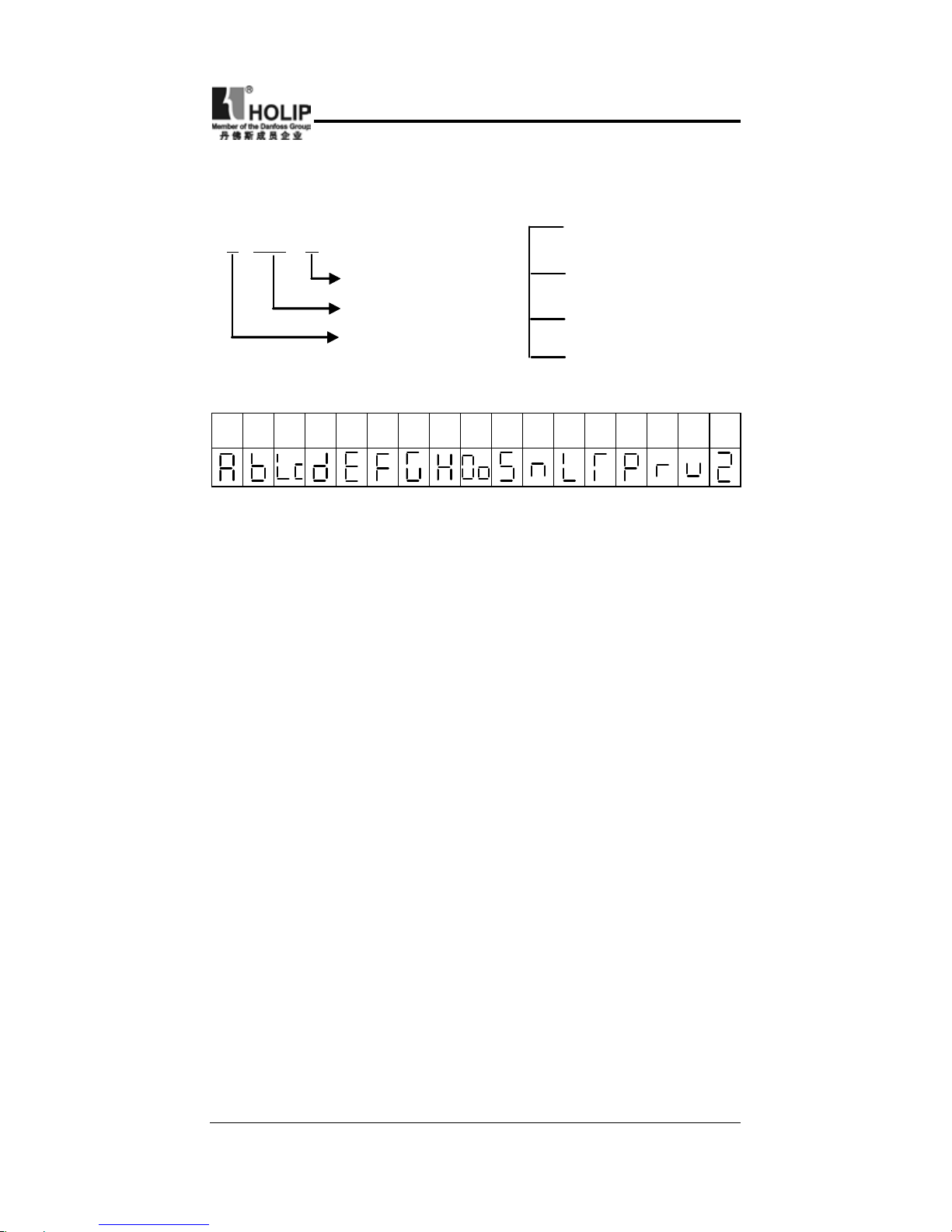
- 85 -
HLP-C
+
Inverters
Note:
⑴
Fault Code Form:
E XX Y
Status
Alarm message
Fault
S:in stopping
Y A:at accel
N:at constant speed
D:at decel
A B C D E F G H O S N L T P R U 2
⑵
Code Comparison Table:
(4) Faults and Analysis
⑴
When pressing Run key the motor doesn’t run.
①
The set ting of operat ion mode is wrong, i.e. under the
operation mode of the externally controlled terminal, it is
started by the operator or under the operation mode of the
operator, it is started by the externally controlled terminal.
②
The frequency command is too low or not given.
③
The peripheral wiring is wrong. For example, the setting of
wiring of two-wire system and three-wire system and other
related parameters have errors.
④
The setting of multi-funct ion t erminals is wrong(in the
external control).
⑤
The inverter is in the fault protection status.
⑥
The motor fails.
⑦
The inverte fails
⑵
The parameters can be set.
①
Password lock. Please decrypt it before setting it again.
②
The inverter is in running.
③
The connection of the connecting parts is abnor mal. The
communication of Digital operator is abnormal. Take out the
operator after poweroff and then mount it again for a trial.
Page 90

- 86 -
HLP-C
+
Inverters
⑶
The motor can rotate reversely.
Reverse rotation is forbidden.
⑷
The motor rotatess in the opposite direction.
The output lines have been wrongly connected. Please change
any three lines of U.V.W over.
⑸
The deceloration of the motor is too slow.
①
The setting of Decel Time is too long. Decrease Decel Time.
②
Add a braking resistor.
③
Add a DC brake.
⑹
Overheat of the motor
①
Too big load. The actual torgue has exceeded the rated torgue
of the motor. It is recommended to increase the capacity of
motor.
②
The ambient temperature is too high. In a place with higher
teperaturethe motor will be burn out. Please decrease the
temperature around the motor.
③
The phase t o phase withstand volt a ge of t he motor is
insufcient.
The actions of seitches of the inverter will make the winding coil
of tehmotor produce shock wave. Normally the maximum shock
voltage will reach 3 times that of input power supply of the
inverter. Please select a motor with the phase to phase withstand
voltage against shock higher than the maximum shock voltage.
⑺
The starting of the inverter interferes other control devices
①
Lower the carrier frequency and reduce the number of actions
of the internal switches.
②
Install a noice lter on the input side of power supply of the
inverter.
③
Install a noice lter on the output side of the inverter.
④
Make correct grounding for the inverter and the motor.
⑤
Use metal tube to cover the cable to shield it.
⑥
Make separate wiring for the maon circuit wires and control
wires.
Page 91

- 87 -
HLP-C
+
Inverters
⑻
When the fan starts an overcurrent stall is detected with the
inverter.
①
At starting the fan rotates disorderly. Please set it for DC
braking at starting.
②
DC braking at starting has been set. Please increase the DC
braking value.
⑼
The machine has the noise of vibration and roar
①
The vibration frequency of mechanical system resonates with
the carrier. Adjust the carrier to avoid the point of resonance.
②
The vibration frequency of mechanical system resonates with
the output frequency of the inverter.
a:Set skip function to avoid the point of resonance..
b:Put rubber vibration isolator on the base plate of motor.
Page 92

- 88 -
HLP-C
+
Inverters
XI. Selection of Peripheral Devices and Disposition
(1) Options
Description Functions
NFB or Ground
fault interrupter
for wire
connection
Protect the wiring of the inverter. Be sure
to connect a breaker to the power supply
line. Please select a grou nd fault circuit
interrupter against high-order harmonics.
Electromagnetic
contactor
In order to prevent the braking resistor from
burning out, please add an electromagnetic
contactor and connect a surge absorber to the
coil when using it.
Surge absorber
Absorb the switching surge current from the
electromagnetic contactor and control relays.
Isulating
transformer
Its function of isolating the input and output
of the inverter is effect ive to reduce the
interference to other electric devices.
DC reactor
I m p rove t h e input p ower f a ct o r of the
inverter.
AC reactor
Improve the input powerfactor of the inverter
and prevent the shock of surge voltage.
Braking resistor,
brtaking unit
Consume the regenerating energy of motor
and shorten the deceleration time.
⑴
Leakage switch
There is earth st atic capacity inside of the inverter and the
motor as well asthe input and output leads. Due to higher carrier
frequency of the inverter the inverter has higher earth leakage
current, especially for serial inverters of large capacity. When
using a leakage switch it may sometimes result in the errous
action of the protective circuit. So when using a leakage switch
attention shoud be paid to its selection and the proper reduction
of carrier frequency and shortening the leads, etc.
⑵
AC reactor
An AC reactor can constrict the high-order harmonic of input
Page 93

- 89 -
HLP-C
+
Inverters
Model Current Inductance(mH
)
00D423B 2.5 4.2
0D7523B 5.0 2.1
01D523B 10 1.1
02D223B 15 0.71
0D7543B 2.5 8.4
01D543B 5.0 4.2
02D243B 7.5 3.6
⑵
AC reactor
Model Current(A
)
Inductance(mH
)
220V
class
00D423B 2.5 4.2
0D7523B 5 2.1
01D523B 10 1.1
02D223B 15 0.7
current of the inveter to improve its input power factor and
prevent the shock of surge. It is recommended to use an input
AC reactor under the following circumstances:
a:Unbalancing of three-phase power supply.
b:Any equipment with thyristors or power factor compensation
unit with switching control connected to the same power
supply.
⑶
DC reactor
It is necessary to install a DC reactor when the capacity of power
supply is more than 1000 KVA ot the grid capacity is higher than
the rated capacity of the inverter. An DC reactor is also needed
for the case with higher demand on the improvement of power
factor of power supply. This DC reactor can be used together
with an AC reactor to achieve the obvious effect of decreasing
high-order harmonic of input. If it is necessary to install a DC
reactor please contact the local distributor.
(2) Disposition
⑴
DC reactor
Page 94

- 90 -
HLP-C
+
Inverters
Inverter model
Specication
Braking torgue
10%ED
Special Motor
KW
W Q
HLPC+00D423B 80 200 125 0.4
HLPC+0D7523B 100 200 125 0.75
HLPC+01D523B 300 100 125 1.5
HLPC+02D223B 300 70 125 2.2
HLPC+0D7543B 80 750 125 0.75
HLPC+01D543B 300 400 125 1.5
HLPC+02D243B 300 250 125 2.2
⑶
Braking resistor
Note:
①
Please select the resistor value and working frequency given
by our company.
②
If it caused any damage to the inverter and other devices due
to the use of any braking resistor and braking model group
not supplied by our company, we will take no responsibility.
③
Be sure to consider the safe t y of t he e nviron me nt and
ignitability when installing a braking resistor. The distance
to the inverter should be 100 mm.
④
If it is necessary to change the resistor value and power value,
please contact the local distributor.
⑤
In need of a braking resistor a separate order must be placed.
Please contact the local distributor for details.
⑥
For any mach ine wit h larger ine r tia the capacity of the
braking resistor should be increased. Please contact the local
distributor for details.
Model Current(A
)
Inductance(mH
)
380V
class
0D7543B 2.5 8.4
01D543B 5 4.2
02D243B 7.5 3.6
Page 95

- 91 -
HLP-C
+
Inverters
Action Description:
①
XII. Appendices
Appendix 1: Simple Application Example
1. Common application example of analog and multi-speed steps
Requirement: The frequency for the rst step is given by analog
quantity. Afterswitching with a swith turn to the operation of
external multi-speed.
K1State K2 State Running Frequency
OFF OFF Given by the potentiometer
ON OFF Speed Step 2 (15Hz)
OFF ON Speed Step 3 (30Hz)
ON ON Speed Step 4 (25Hz)
②
For/Rev switching can be carried out by switching of multifunction terminals or switching of For/Rev on the panel ( The
switching of For/Rev on the panel is adopted in this example.)
Page 96

- 92 -
HLP-C
+
Inverters
2. On common drive of multi inverters.
Note:
①
The f requency of the main machine can be s et by t he
potentiometer.
②
The proportional relation of each inverter can be adjusted by
C075.
For exam ple, w h e n F
变频
1
:
F
变频
2
:
F
变频
3
=1:2:3,th e n the
parameter of C075can be changed to: Inverter 1:C075=50
,
Inverter 2:C075=100,Inverter 3:C075=150,when the analog
quantity is 10V, the corresponding frequencies are respectively
50Hz,100Hz,150Hz with the proportional relation of 1:2:3.
③
For easy operation and adjustment a ne tuning potentiometer
can be added. Please check and consult for details.
Page 97

- 93 -
HLP-C
+
Inverters
3. Parameter setting for the application of fast stopping
When using it in the application of loom demanding on fast
stopping the parameter setting is recommended as follows:
①
Decel Time is set to 0.1S.
②
Give a certain DC braking quantity at stopping (if necessary
install additional braking resistor.
③
Voltage stall prevention is set to invalid.
④
In need of positioning, 2 ~3-speed steps can be used for
adjustment.
Appendix 2: External Appearance and Installation Dimensions
Page 98

- 94 -
HLP-C
+
Inverters
Model A B C D E F
HLPC+00D423B
74 85 130 141.5 113 ф5
HLPC+0D7523B
HLPC+01D523B
HLPC+02D223B
89 100 140 151.0 116.5 ф5
HLPC+0D7543B
HLPC+01D543B
HLPC+02D243B
4. Explanation of Operator Model
OP-C B-04
C serial keypad
B Version
C Series
OPERATOR
3. Operator’s External Appearance and Size (Unit: mm)
70
Page 99

- 95 -
HLP-C
+
Inverters
Appendix 3: User’s Records and Feedback
Code Function
Factory
Setting
User’s
Parameter
Code Code
Factory
Setting
User’s
Parameter
C000
Main
Frequency
Set
0.0 C014 Select 0
C001
Accel Time
Set
5.0 C015
Stopping
Mode
Select
0
C002
Decel Time
Set
5.0 C016
Rev rotation
allowable
1
C003 V/F Curve * C017
STOP key
select
1
C004
Highest
Voltage Set
220/380
C018
S-curve
time set
0
C005
Base
Frequency
Set
50/60 C019
Carrier
frequency
select
09
C006
Intermediate
Voltage Set
* C020
Starting
frequency
set
1.5
C007
Intermediate
Frequency
Set
* C021
Stopping
frequency
select
1.5
C008
Min.
Voltage Set
* C022
Jog requency
select
5
C009
Min.
Frequency
Set
* C023
Jog accel/
decel
select
1.0
C010
Highest
Frequency
Set
50 C024
PLC
operation
select
0
C011
Lower
Limit
Frequency
Set
0 C025
Auto PLC
operation
select
0
C012
Running
Control
0 C026
Speed
search time
0
C013
Running
Frequency
Select
0 C027
PLC accel/
decel time 1
0
Page 100

- 96 -
HLP-C
+
Inverters
Code Function
Factory
Setting
User’s
Parameter
Code Code
Factory
Setting
User’s
Parameter
C028
PLC
accel/decel
time 2
0 C046
PLC Timer
5 Set
0
C029
Accel Time
2 Set
10 C047
PLC Timer
6 Set
0
C030
Decel Time
2 Set
10 C048
PLC Timer
7 Set
0
C031
Accel Time
3 Set
50 C049
PLC Timer
8 Set
0
C032
Decel Time
3 Set
50 C050
Multiinput FOR
02
C033
Accel Time
4 Set
100 C051
Multiinput REV
03
C034
Decel Time
4 Set
100 C052
Multiinput RST
10
C035
Frequency
2
15 C053
Multiinput SPH
17
C036
Frequency
3
20 C054
Multiinput SPM
18
C037
Frequency
4
25 C055
Multiinput SPL
19
C038
Frequency
5
30 C056
Multiinput DRV
01
C039
Frequency
6
35 C057
Multi-input
FABC
02
C040
Frequency
7
40 C058
Multianalog AM
0
C041
Frequency
8
0.5 C059
AM output
gain of analog
quantity
100
C042
PLC
Timer 1 set
10 C060
UP-DOWN
mode
0
C043
PLC
timer 2 set
10 C061
UP-DOWN
speed rate
0
C044
PLC
Timer 3
Set
0 C062
Timer 1
Set
0
C045
PLC Timer
4 Set
0 C063
Timer 2
Set
0
 Loading...