

Page 1
Page 2

HLP-A100 Series Operating
Manual
Page 3

Page 4

HLP-A10 0 Ser ies
HLP-A100 Series Operating Manual
Index
Introduction 1
Chapter 1 Safty Precautions 1
1.1 Before power-up 1
1.2 During the power-up 3
1.3 During the operation 3
1.4 After the power-off 4
Chapter 2 Standards and Specications 5
2.1 Label Description 5
2.2 Particular Specications 6
2.3 Technical Specications 7
Chapter 3 Installation and wiring 11
3.1 Checks before Installation 11
3.2 Installation Dimensions 11
3.2.1 Dimensions of LCP 11
3.2.2 Dimensions of the inverter 12
3.3 Installation and Wiring 13
3.3.1 Electrical Installation in General 13
3.3.2 Fuse and Main Circuit Terminals Specications 13
3.3.3 Installation and Direction 14
3.3.4 Wiring terminal 15
3.3.5 Wiring 19
Chapter 4 Operation and Display Interface 21
4.1 LCP Digital Operator 21
4.2 Quick to set parameters 21
4.2.1 Preset reference by LCP 21
4.2.2 FWD/REV Status 22
4.2.3 Data read-outs 23
4.2.4 View alarm record 25
4.2.5 View state parameter 26
4.2.6 LED Display 27
Chapter 5 Parameter Overview 28
Chapter 6 Parameter Description 54
6.1 Parameter Group 00: Operation/Display 54
6.2 Parameter Group 01: Load and Motor 59
6.3 Parameter Group 02: Brakes 69
6.4 Parameter Group 03: Reference/Ramps 72
6.5 Parameter Group 04: Limits/warnings 81
6.6 Parameter Group 05: Digital Input/Output 86
Page 5

HLP-A100 Series Operating Manual
HLP-A10 0 Ser ies
6.7 Parameter Group 06: Analog In/Out 95
6.8 Parameter Group 07: Controller 103
6.9 Parameter Group 08: Comm. and Options 106
6.10 Parameter Group 13: Simple PLC 110
6.11 Parameter Group 14: Special Functions 118
6.12 Parameter Group 15: Drive Information 123
6.13 Parameter Group 16: Data Readouts 127
6.14 Parameter Group 25: App. Functions Cascade 136
6.15 Parameter Group 30: App. Functions Wobble 145
Chapter 7 Quick Application Guide 150
7.1 Motor Parameter Adaption 150
7.2 Using LCP to control the drive [HAND] 150
7.3 Using digital in terminals to control the drive [AUTO] 151
7.4 Set-up selection 151
7.5 Potentiometer reference 152
7.6 Connect two-wire transductor to terminal AI 152
7.7 Reference for pulse input 153
7.8 Multi-speed 153
7.9 Speed up/down 154
7.10 Pulse start/stop 155
7.11 Digital speed up/down 155
7.12 Conguration Mode 156
7.13 Simple PLC 158
7.13.1 Order Execution 158
7.13.2 Parallel Execution 160
Chapter 8 Accessory Specication 161
8.1 Braking Resistor 161
8.2 Remote Mounting Kit 162
Chapter 9 EMC 163
9.1 EMC–Correct Installation 163
Chapter 10 Warnings/Alarms and Fault Handling 164
10.1 Fault List 164
10.2 Fault Indication and Trouble Shooting 168
Chapter 11 Maintenance 170
11.1 Note 170
11.2 Storage and Transport 170
Chapter 12 Communication protocol 171
12.1 Format specication 171
12.2 Coil addressing 171
12.3 Read Coil Status 173
12.4 Read Holding Registers 174
12.5 Force Single Coil 175
Page 6

HLP-A10 0 Ser ies
HLP-A100 Series Operating Manual
- 5 -
12.6 Preset Single Register 175
12.7 Force Multiple Coils 176
12.8 Preset Multiple Regs 177
12.9 Read/Write array 178
12.10 Exception code 179
Page 7

HLP-A100 Series Operating Manual
HLP-A10 0 Ser ies
- 6 -
Page 8
HLP-A10 0 Ser ies
HLP-A100 Series Operating Manual
- 1 -
Caution
● Check to be sure that the voltage of the main circuit AC power
supply matches the input voltage of the inverter.
● Install the inverter in a safe location, avoiding high temperature,
direct sunlight, humid air or water.
● The inverter can only be used at the places accredited by our
company. Any unauthorized working environment may have the
risks of re, gas explosion, electric shock and other incidents.
● If more than one drive installed on the same control cabinet, make
additional cooling fan, so that the inside temperature is lower than
40
℃
,
in order to prevent overheating or re occurs.
● It will affect the service life of the inverter if a contactor is
Introduction
Thank you f or purchasing and using the general-purpose vector
inverter of HLP-A100 series.
Please read caref ully the operation manual before putting the inver ter
to use so as to correctly install and operate the inverter, give f ull play to its
f unctions and ensure the safet y. Please keep the operation manual handy for
f uture reference, maintenance, inspection and repair.
Due to the inverter of a kind of power electronics product it must be
installed, tested and ad justed with specialized electrical engineering workers.
The ma r ks of
(Da nger)
、
(Caution) a nd other symbols in
the manual remind you of the safety and prevention cautions during
the handling, installation, running and inspection. Please follow these
instr uctions to make su re the safe use of the inverter. In case of any doubt
please contact our local agent f or consultation. Our professional persons are
willing and ready to serve you.
The manual is subject to change without notice.
Chapter 1 Safet y Precautions
1.1 Before power-up
Caution
Indicates misuse may damage the inverter or
mechanical system .
Danger
Misuse may result in casualty.
Page 9
HLP-A100 Series Operating Manual
HLP-A10 0 Ser ies
- 2 -
Danger
● Be sure to turn off the power supply before wiring.
● Mount the drive in the metal and other non-combustible materials
to avoid the risk of re.
● Don’t install the drive in a space with explosive gas, otherwise,
they lead to explosion.
● R, S, T terminals are power input terminals, never mixed with
U.V.W terminals. Be sure that the wiring of the main circuit is
installed on the input side to control the start and stop. Generally
it is required to control it through terminal commands. Special
attention should be paid to its use in the case of the start and stop
more frequently places.
● Do not install any switch component like circuit breaker or
contactor at the output of the inverter. If any of such components
must be installed due process and other needs, it must be ensured
that the inverter has no output when the switch acts. In addition,
it is forbidden to install any capacitor for improvement of power
factor or any varistor against thunder at the output. Otherwise
it will cause malfunctions, tripping protection and damages of
components of the inverter.
● Please use an independent power supply for the inverter. Do avoid
using the common power supply with an electrical welder and
other equipment with strong disturbance. Otherwise it will cause
the drive to protect or even damage the drive.
● Motor overload protection is not included in the default settings. If
this function is desired, set C01.09 (motor thermal protection) to
date value ETR trip or date value ETR warning.
● Do not make any high voltage test with any component inside the
inverter. These semi-conductor parts are subject to the damage of
high voltage.
● The IC board of the inverter are susceptible to the effect and
damage of static electricity. Don’t touch the main circuit board.
● Installation, commissioning and maintenance must be performed
by qualied professional personnel.
● Don’t carry the front cover of the inverter directly when handling.
It should be handled with the base to prevent the front cover off
and avoid the dropping of the inverter, which may possibly cause
the injuries to people and the damages to the inverter.
Page 10
HLP-A10 0 Ser ies
HLP-A100 Series Operating Manual
- 3 -
correct. Otherwise it will cause damages of the inverter when the
power is applied to it.
● The terminal of
must be grounded separately and never
connected to N-line. Otherwise it will easily cause the protection
or errors of the inverter.
● Do not dissemble or modify any internal connecting cord, wiring
or component of the inverter by yourself.
● Never remodel it or exchange control boards and components by
yourself. It may expose you to an electrical shock or explosion,
etc.
● Keep the inverter from the reach of children or persons not
concerned.
Caution
● Do not measure the signals on circuit boards while the inverter is
running to avoid danger.
● The drive has been optimized before sold. Please make proper
adjustments according to the desired functions.
● Do consider the vibration, noise and the speed limit of the motor
bearings and the mechanical devices.
Danger
● Do not plug the connectors of the inverter during the power up
to avoid any surge into the main control board due to plugging,
which might cause the damage of the inverter.
● Always have the protective cover in place before the power up to
avoid electrical shock injury.
Danger
● Never connect or disconnect the motor set while the inverter is in
running. Otherwise it will cause over-current trip and even burn
up the main circuit of the inverter.
1.2 During the power-up
1.3 During the operation
Page 11
HLP-A100 Series Operating Manual
HLP-A10 0 Ser ies
- 4 -
Caution
● Even in the case of the main power, the other voltage inputs and
the share load (linkage of DC intermediate circuit) all have been
disconnected from the mains, the internal of the drive still have
residual energy. Before touching any potentially live parts of the
inverter, please wait at least 4 minutes for the drives of less than
22KW (including 22KW), and wait at least 15 minutes for the
drives of more than 30kW (including 30kW). Otherwise, it will
expose you to a risk of electrical shock.
The user must strictly follow the instruction to operate and make
wire connection. Otherwise HOLIP will not responsible for the
damages due to wrong operation. The user will responsible for the
damages themselves.
● Never remove the front cover of the inverter while the inverter is
powered up to avoid any injury of electric shock.
● Do not come close to the machine when the Reset Function is
used to avoid anything unexpected. The motor may automatically
recover from fault.
1.4 Af ter the power-off
Page 12
HLP-A10 0 Ser ies
HLP-A100 Series Operating Manual
- 5 -
Chapter 2 Standards and Specications
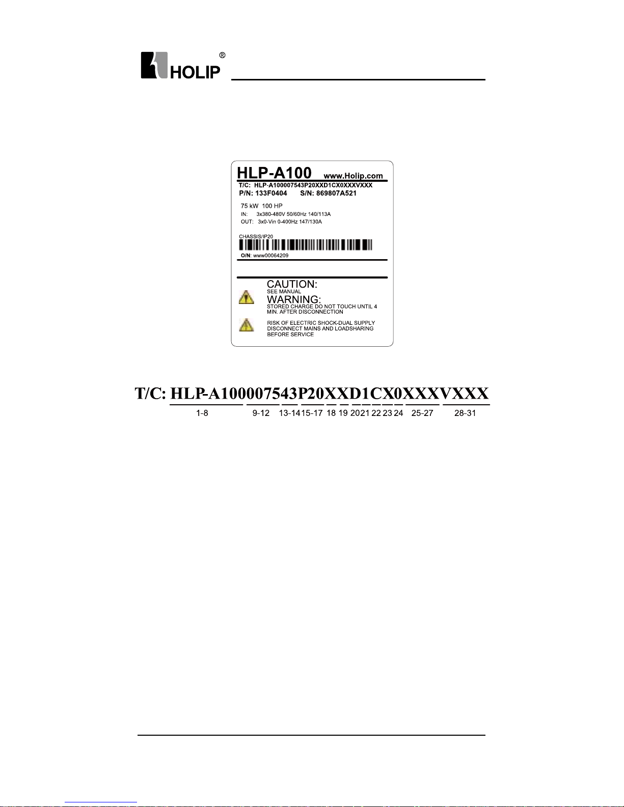
2.1 La be l Descr i pt ion
Signicance of the type code:
1-8 HLP-A100 Indicate Product Series
9-12 0075 I n dica te 75K W
13-14 21 Indicate 1-Phase AC 220V
23 Indicate 3-Phase AC 220V
43 Indicate 3-Phase AC 380V
15-17 P20 IP rating is 20
18 X Without AC choke
A With AC choke
19 X Without Brake unit
B With Brake unit
20 X Without DC choke
D With DC choke
21 1 Control panel with LED display and potentiometer
22 C Wit h coating on PCB
23 X Reser ved
24 0 Domestic sale
1 Overseas sale
25-27 XX Reser ved
28-31 VXXX Indicate sof tware version number,
such as V235 means the version number is 2.35 .
Page 13

HLP-A100 Series Operating Manual
HLP-A10 0 Ser ies
- 6 -
2.2 Particular Specications
Model Inpu t voltage
Input
current/
A
Output
current/
A
Rated
power/
KW
Suitable
motor/
KW
Net
weight /
KG
HLP-A100001143
3×380 - 4 40 V 5 0 /6 0 H z 35.9 25
11 11 5.8
3×4 4 0 - 48 0 V50 /6 0 Hz 31. 4 22.7
HLP-A100001543
3×380 - 4 40 V 5 0 /6 0 H z 43. 4 32
15 15 5.8
3×4 4 0 - 48 0 V50 /6 0 Hz 38.8 29.1
H L P- A10 018 D 5 43
3×380 - 4 40 V 5 0 /6 0 H z 51.5 38
18. 5 18. 5 8
3×4 4 0 - 48 0 V50 /6 0 Hz 4 6.1 34.5
HLP-A100002243
3×380 - 4 40 V 5 0 /6 0 H z 61.0 45
22 22 8
3×4 4 0 - 48 0 V50 /6 0 Hz 54.5 4 0.9
HLP-A100003043
3×380 - 4 40 V 5 0 /6 0 H z 57 61
30 30 25. 4
3×4 4 0 - 48 0 V50 /6 0 Hz 46 52
HLP-A100003743
3×380 - 4 40 V 5 0 /6 0 H z 70 73
37 37 2 5.4
3×4 4 0 - 48 0 V50 /6 0 Hz 57 65
HLP-A100004543
3×380 - 4 40 V 5 0 /6 0 H z 84 90
45 45 50
3×4 4 0 - 48 0 V50 /6 0 Hz 68 80
HLP-A100005543
3×380 - 4 40 V 5 0 /6 0 H z 103 10 6
55 55 50
3×4 4 0 - 48 0 V50 /6 0 Hz 83 105
HLP-A100007543
3×380 - 4 40 V 5 0 /6 0 H z 14 0 147
75 75 50
3×4 4 0 - 48 0 V50 /6 0 Hz 113 130
HLP-A100009043
3×380 - 4 40 V 5 0 /6 0 H z 175 18 0
90 90 60
3×4 4 0 - 48 0 V50 /6 0 Hz 15 4 16 0
H L P- A10 0 0110 43
3×380 - 4 40 V 5 0 /6 0 H z 206 215
110 11 0 60
3×4 4 0 - 48 0 V50 /6 0 Hz 18 3 19 0
HLP-A100013243
3×380 - 4 40 V 5 0 /6 0 H z 2 51 260
132 132 60
3×4 4 0 - 48 0 V50 /6 0 Hz 2 31 240
HLP-A100016043
3×380 - 4 40 V 5 0 /6 0 H z 304 315
16 0 16 0 99
3×4 4 0 - 48 0 V50 /6 0 Hz 2 91 302
HLP-A100018543
3×380 - 4 40 V 5 0 /6 0 H z 350 365
185 185 99
3×4 4 0 - 48 0 V50 /6 0 Hz 320 335
HLP-A100020043
3×380 - 4 40 V 5 0 /6 0 H z 381 395
200 200 99
3×4 4 0 - 48 0 V50 /6 0 Hz 348 361
HLP-A100022043
3×380 - 4 40 V 5 0 /6 0 H z 420 435
220 220 99
3×4 4 0 - 48 0 V50 /6 0 Hz 383 398
Page 14
HLP-A10 0 Ser ies
HLP-A100 Series Operating Manual
- 7 -
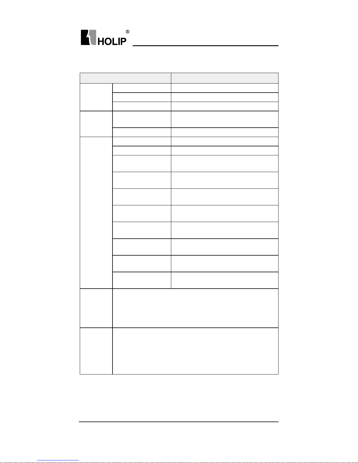
2.3 Technical Specications
Item Specif ication
Power
su pply
Supply voltage three phase 380-480V -20%-+10%;
Frequency 48-62Hz;
Max. imbalance 3%;
Motor
output
Output voltage
three phase 0-100% of supply
volt a ge;
Output f requency V/F : 0-400Hz , VVC+: 0-200Hz;
Main
con t rol
f unctions
Cont rol mode V/ F, V VC+;
Sta rt torque 1H z 150 %;
Overload capacity
150% rated output current (60s),
200% rated output current(1s);
PWM switch
f requency
2 K-16 K H z ;
Speed setting
resolution
Dig i t al: 0.001Hz; a nalog y: 0.5‰ of t h e
max. operating f requency ;
Speed open-loop
cont rol accuracy
30 - 4000 r pm: tolerance±8 rpm;
Speed closed-loop
cont rol accuracy
0 - 6000 rpm: tolerance±0.15 r pm;
Cont rol com ma nd
source
LCP , digital terminal, local bus;
Frequency setting
source
LCP , analog, pulse, local bus;
Ramp control
Selectable 4-speed steps ramp up and
down times 0.05-3600.00s;
Basic
Functions
AMA Function; Motor Magnetisation; Slip Compensation;
Torque compensation; Automatic Voltage Regulation; V/
F Control, DC Brake; AC brake; Speed Limit; Cu r rent
Limit; Flying Star t; Reset Function; Cou nter; Timer; PI
Controller.
Application
Functions
Speed Open-loop Control; Process Closed-loop Cont rol;
Wobble Function; Cascade controller; Winder; Jogging
; Multi-speed Control via Digital input; Multi-speed
Control via Reference; SLC ( including Order Control
、
Parallel Control ) ; Mechanical Braking;UP/DOWN;Catch
up /Slow down; Relative Scaling Reference etc.
Page 15
HLP-A100 Series Operating Manual
HLP-A10 0 Ser ies
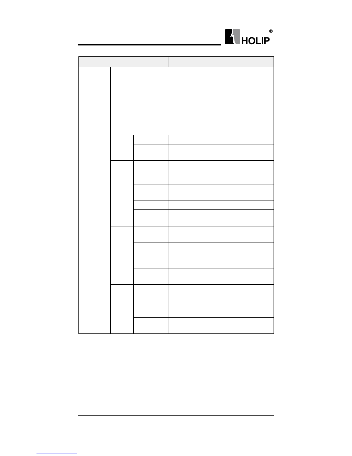
- 8 -
Item Specif ication
Protection
Functions
Missing Motor Phase Protection; Low-voltage Protection;
Over-voltage Protection; Over-current Protection; Output
Phase Loss Protection; Output Short Circuit Protection;
Output Grounding Fault Protection; Motor Thermal
Protection; Live Zero Timeout Function; AMA Fails;
CPU Fault; EEPROM Faults; Button freeze; Duplicate
Fails; LCP Invalid; LCP Incompat ible; Parameter Readonly; Reference Out of Range; Invalid While Running;
Password Er ror etc.
Cont rol
Te r mi na ls
Digital
input
Number 6 d igital i n pu ts.
Scan ni ng
time
1ms;
Analog
input
Numbe r of
input
2 analog inputs ( VI 、 AI ) , both
can receive voltage or cur rent
signals.
Input
accuracy
Max.er ror: 0.5% of f ul l scale
Resolution 11 b i t ;
Scan ni ng
time
1ms;
Pulse
input
Input
nu mber
1 pulse input ( DI4 ) , pulse
range:1Hz-100K Hz;
Input
accuracy
Max.er ror:0.5% of f ul l scale;
Resolution 11 b i t ;
Scan ni ng
time
16 m s ;
Digital
output
Output
nu mber
2 digital out puts ( DO1 、 DO2 )
Relay
output
2 relay outputs ( KA-KB 、 FA- F BFC ) ;
Scan ni ng
time
1ms;
Page 16

HLP-A10 0 Ser ies
HLP-A100 Series Operating Manual
- 9 -
Item Specif ication
Cont rol
Te r mi na ls
Analog
output
Output
nu mber
2 analog outputs ( VO 、 AO ) , VO
can be selected to the current output
or voltage output via jumper switch
in the control board. AO can only be
selected as cu r rent output . Up to 11
dif ferent f eatures can be selected;
Output
accuracy
Max. error: 4‰ of f ull scale;
Resolution 11 b i t ;
Scan ni ng
time
16 m s ;
Pulse
output
Output
nu mber
1 pulse output (DO1), range: 1Hz-
2KHz (range f rom 1Hz-100KHz is
optional);
Output
accuracy
Max.er ror: 0.5% of f ul l scale;
Resolution 11 b i t ;
Scan ni ng
time
16 m s ;
Power
su pply
VDD 24VDC power supply;
+10 V 10 V D C p o w e r s u p p l y ;
RS485
serial
commu-
nication
Te r mi na l
nu mber
1, RS+(TX+,RX+), RS- (TX-, RX-);
Ground for
RS485
GN D;
Display
8 segments, 5
numeric displays
Display f requency, wa r nings, status
and so on;
Indicator
Light FWD 、 REV 、 HZ 、 A 、 R/
MIN display various status of the
inverter;
Data read-outs
Frequency setting, output f requency,
feedback value, out put current, DC
link voltage, output voltage, output
power, input terminals state, output
terminals state, analogue input ,
analogue output, 1-10 fault records
and accumulated working time etc.;
Accessor y
Remote mounting
kit
Available when the control panel f or
external use;
Copy card
Copy parameters f rom one inverter
to another ;
Page 17
HLP-A100 Series Operating Manual
HLP-A10 0 Ser ies
- 10 -
Item Specif ication
Environment
Enclosure IP 20;
Ambient
temperat u re
-10℃ - 40℃ ;
Humidity 5%-85% ( 95% wi t hou t conde nsa tion);
Vibration test ≤ 75K W:1.14g;90 - 2 2 0K W:0.7g;
Max. altitude above
sea level
1000m, derating use when more than
1000 meters;
Motor ca ble length
Shield ca ble: 50 meters, u nshield
cable: 100 meters;
Others
DC Choke ≥30kW with DC choke;
Brake Unit ≤22KW with Brake Unit;
Attention: Inverter under special environment (derating
)
:
● Derating for ambient temperature: If the f requency converter is
operated over 40
℃
ambient temperature, the continuous output
current should be decreased. The f requency converter has been
designed for operation at max 50
℃
ambient temperation with one
motor size smaller than normal. Continuous operation at full load at
50
℃
ambient temperation will reduce the lifetime of the f requency
converter.
● Derating for low air pressure: The cooling capability of air is
decreased at low air pressure. Below 1000m altitude no de-rating is
necessary but above 1000m the ambient temperature or the maximum
output current should be decreased. Dcrease the output by 1% per
100m altitude above 1000m or reduce the max. ambient temperature
by 1 degree per 200m.
Page 18

HLP-A10 0 Ser ies
HLP-A100 Series Operating Manual
- 11 -
Chapter 3 Installation and wiring
3.1 Checks before Installation
3.2 Installation Dimensions
3.2.1 Dimensions of LCP
The inverter has been strictly and well packed before sold. In
consideration of various factors during the transportation special attention
should be paid to the following points before installation. If there is anything
abnor mal please notif y the dealer or the relevant people of our company.
● Check if the inverter has got any damage or deformation during the
transportation and handling;
● Check if there is one piece of HLP-A100 series inverter and one copy
of the instruction manual available when unpacking it;
● Check the information on the label to see if the specications meet
your order (Operating voltage and KW value);
● Check if the optional components you ordered are contained;
● Check if there is a certicate of qualication and a warrant y card.
Dimensions of the LCP are shown below (unit: mm):
Page 19
HLP-A100 Series Operating Manual
HLP-A10 0 Ser ies
- 12 -
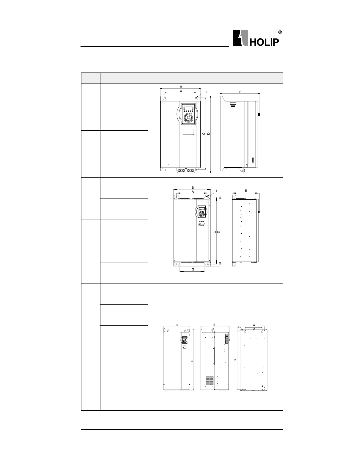
3.2.2 Dimensions of the inverter
Item Model Frame size and Installation Dimension
A3
HLP-A100001143
HLP-A100001543
A4
H L P - A10 018 D5 4 3
HLP-A100002243
A5
HLP-A100003043
HLP-A100003743
A6
HLP-A100004543
HLP-A100005543
HLP-A100007543
A7
HLP-A100009043
H L P- A10 0 0110 4 3
HLP-A100013243
A8 HLP-A100016043
HLP-A100018543
HLP-A100020043
Page 20
HLP-A10 0 Ser ies
HLP-A100 Series Operating Manual
- 13 -
Installation dimensions of the inverter:
Details of terminal tightening torques:
3.3 Installation and Wiring
3.3.1 Electrical Installation in General
Caution
● All cabling must comply with national and local regulations on
cable cross-sections and ambient temperature. Copper conductors
required.
Power ( KW ) a nd Volt age
levels
Tor qu e ( Nm )
1× 2 0 0 -
240V
3×20 0 -
240V
3×380 -
480V
Line Motor
DC connection/
Bra ke
Cont rol
terminals
Relay
11- 2 2 1. 2 1. 2 1. 2 0.15-0.4 0.4
30-75 8 8 8 0.15-0.4 0.4
90-220 16 16 16 0.15-0.4 0.4
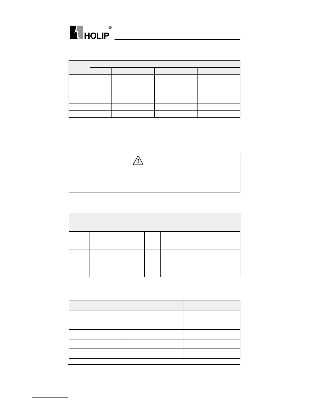
Item
Dime nsion(mm)
A(mm) B(mm) C(mm) D(m m) E (mm) F(mm) G(mm)
A3 148 192 340 365 189 6.5 -
A4 150 214 395 420 194 6.5 -
A5 250 292 530 563 216.5 10 200
A6 280 330 680 720 308 10.5 215
A7 220 350 765 799 375 10.5 280
A8 345 486 863 900 390 10.5 410
3.3.2 Fuse and Main Circuit Terminals Specications
Model Fuse(Rated current/A) Main Circuit Terminals
HLP-A100001143 63 M4
HLP-A100001543 80 M4
H L P - A10 018 D5 4 3 80 M5
HLP-A100002243 10 0 M5
HLP-A100003043 10 0 M8
Page 21
HLP-A100 Series Operating Manual
HLP-A10 0 Ser ies
- 14 -
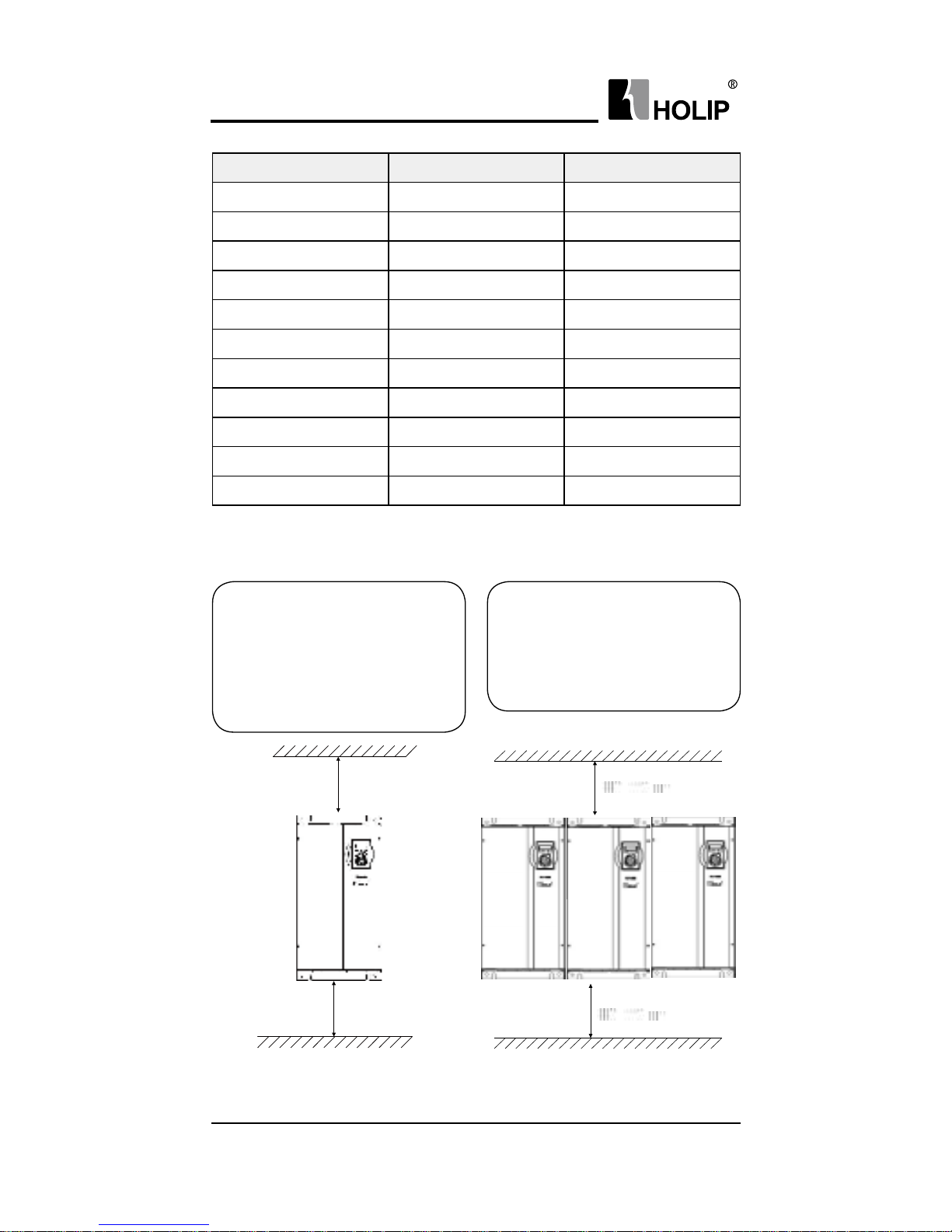
3.3.3 Installation and Direction
Single Installation
The inverter must be installed
vertically with smooth ventilation.
Enough space must be lef t around
the inverter to ensure good cooling,
as show n below:
Min:100mm
Min:100mm
Side by Side Instal lation
HLP-A100 series inverter can be
mou nted side by side, a minimum
space must be reserved above and
below the enclosure, as shown below:
Fig.1 Single installation
Fig.2 Side by side installation
Model Fuse(Rated current/A) Main Circuit Terminals
HLP-A100003743 12 5 M8
HLP-A100004543 16 0 M8
HLP-A100005543 16 0 M8
HLP-A100007543 224 M8
HLP-A100009043 300 M10
H L P- A10 0 0110 4 3 350 M10
HLP-A100013243 400 M10
HLP-A100016043 500 M12*1 ( M10*2)
HLP-A100018543 630 M12*1 ( M10*2)
HLP-A100020043 630 M12*1 ( M10*2)
HLP-A100022043 800 M12*1 ( M10*2)
Page 22
HLP-A10 0 Ser ies
HLP-A100 Series Operating Manual
- 15 -
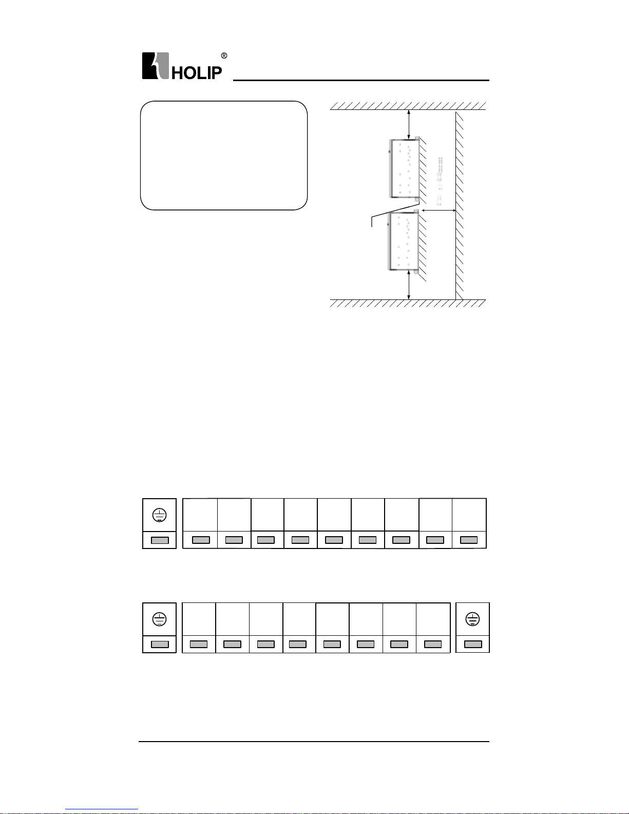
Fig. 3 Upper and Lower installation
Upper and Lower Installation
If several inverters need to be
installed together in one cabinet,
upper and lower installation can
be adopted. Enough space must be
reserved to ensure effective cooling,
as shown right:
Note: Install the unit and make sure that it is f ree f rom high moisture 、 high
temperat u re 、 heavy dust 、 metal f ragments and high oil mist.
3.3.4 Wiring terminal
Min:100mm
Min:100mm
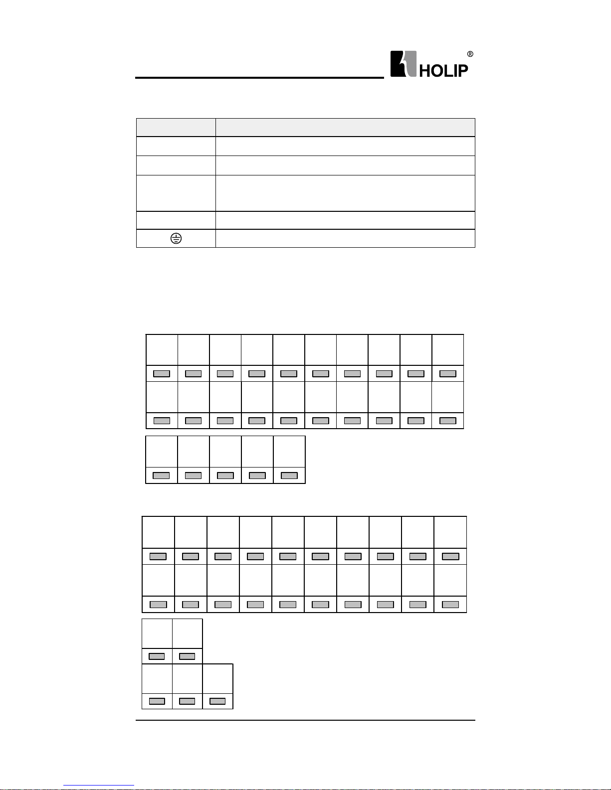
3.3.4.1 Main Circuit Terminals
Terminals of the main circuit:
11- 22k W:
30 - 22 0 K W:
R S
T
VU
W
-UDC
+UDC
-UDC
+UDC/
+BR
TS
U
-BR
R
V
W
Page 23
HLP-A100 Series Operating Manual
HLP-A10 0 Ser ies
- 16 -
3.3.4.2 I/O Control Terminals
Description of main circuit terminals:
30-75kW Control and Relay Terminals:
Symbol Function
R 、 S 、 T Power input
U 、 V 、 W Power output, connect to the motor
-BR 、 +BR
Connect the brake resistor, make sure to set C02.10
、
C 0 2 .11 e t c .
+UDC 、 -UDC DC bus
Ground terminal
11-22kW & 90-220kW Control and Relay Terminals:
RS+ RS-
FORCOM VDDREV
VI
AI
+10V
DI2 DI3 GNDDI4 DO2DO1 VO AODCM
GND
DI1
FA FB
KA FC KB
RS+ RS-
AIVI REVFOR
VDD
DO1
DI1
AO +10V DI2GND DI4DI3 DCM COMCOM
DO2
VO
KA KB
FB FCFA
Page 24

HLP-A10 0 Ser ies
HLP-A100 Series Operating Manual
- 17 -
Description of I/O control terminals:
Symbol Description Specication
VDD
24Vpower
su pply
Max.load 200m A, with over load and
short circuit protection f unctions;
+10 V
10 V po w e r
su pply
Max.load 10 mA, with over load and
short circuit protection f unctions;
Digital input
(FOR、 REV
、
DI1、 DI2、 DI3
、
DI4)
Digital cont rol
terminals
1 、 Log ic:
PNP <DC5V logic ‘0’;
>DC10V logic ‘1’;
NPN >DC19V logic ‘0’;
<DC14V logic ‘1’;
2 、 Vol t age: DC 0 -2 4 V;
3 、 Input resistance: 5KΩ;
4 、 Input voltage rang: max ±28V;
5 、 Switch PNP and NPN model by
Ju mper switch.
Analog input
(VI、 AI)
Analog setting/
Fee d ba ck
Set by the related pa rameter, analog input
channel can be congurated to 0-20mA
o r 0 -10 V:
Vol t age in put:
1 、 Input impedance: about 10 KΩ;
2 、 Maximum withstand voltage is 20V,
duration of 2 seconds, the maximum
reverse
voltage is -15V , du ration of 2seconds.
Current input:
1 、 Input impedence≤500Ω;
2 、 Maximum withstand cur rent is 29
mA duration of 2 seconds.
Analog
、
communication
(GN D)
Analog
、
communication
ground
Isolated f rom inter nal digital
grou n d(COM)
Pulse input DI4
Pulse setting/
Fee d ba ck
1 、 Pulse input: 0.001-100.000KHz;
2 、 Voltage range: 24V ± 20%;
3 、 Input duty ratio: 40%-60%;
Page 25
HLP-A100 Series Operating Manual
HLP-A10 0 Ser ies
- 18 -
Symbol Description Specication
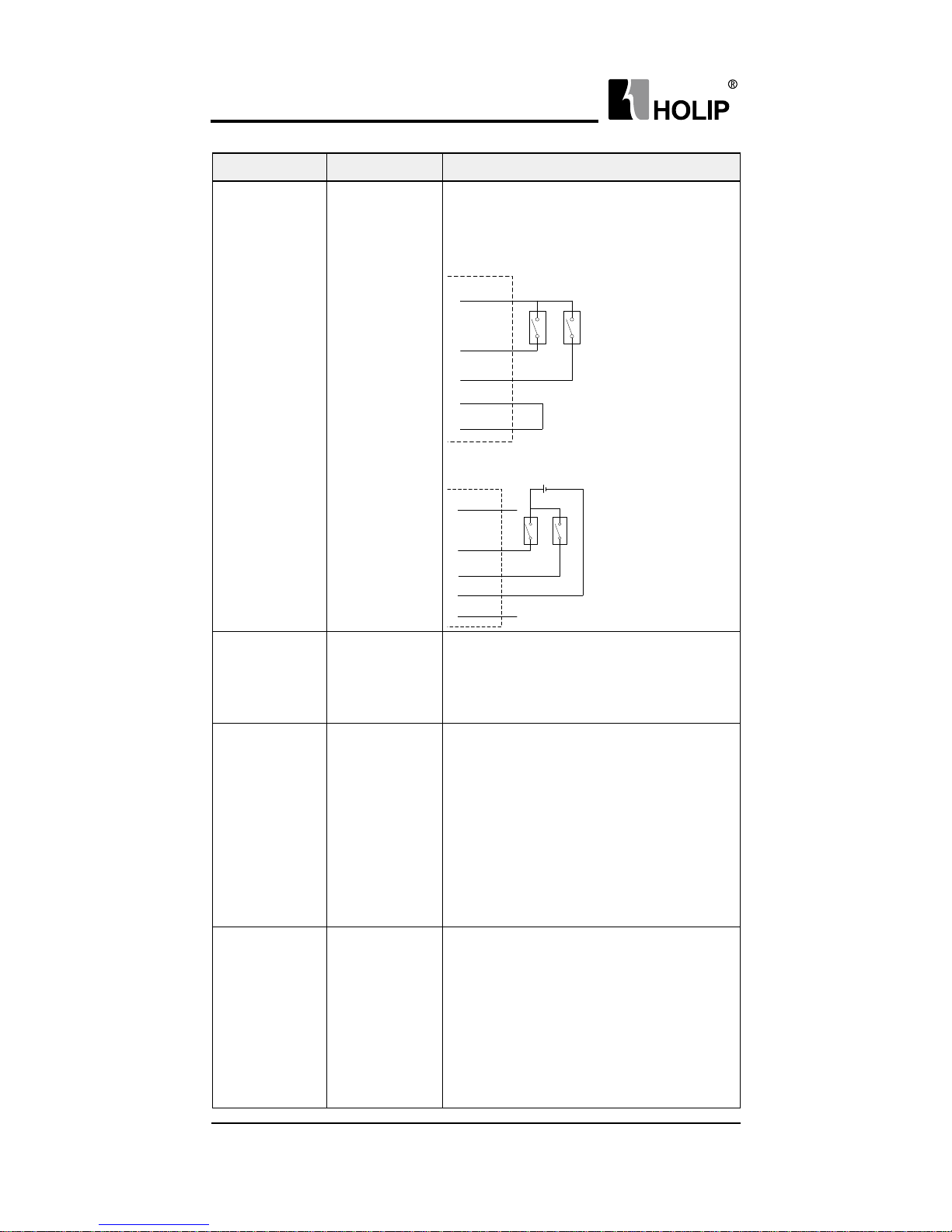
Digital output
( D O1 、 DO2)
Digital output
1 、 Open collector output;
2 、 Output current range: 0-50mA;
3 、 Max voltage 30V;
4、 Two different way to connect relay:
VD D
DO1
DO2
D CM
COM
R e la y 1 R e la y 2
Note: DCM and COM must be connected.
VD D
DO1
DO2
D CM
COM
+ +
Supply
R e la y 1 R e la y 2
Digital output
common
terminal
(DCM)
Digital output
common
terminal
Connect COM as Digital output reference
grou nd wh ile use.
Analog output
(VO 、 AO)
Analog output
VO can be selected to the current output
or voltage output via jumper switch
in the control board. AO can only be
selected as cur rent out put:
1 、 Output mode: 0-20mA or 0-10V;
2 、 Voltage output: Load larger tha n
500Ω;
3 、 Current output: Load larger than
500Ω;
Pulse output
D O1
Pulse output
DO1 can also be congu red as pulse
output channels:
1 、 Pulse output range: 0.001-5.000KHz
(r ange f r o m 0.001-100.000K Hz is opt iona l );
2 、 Voltage range: 0-24V;
3 、 Duty ratio: 40%-60%;
4 、 Resistive load >1kΩ, capacitive load <
10 n F;
Page 26
HLP-A10 0 Ser ies
HLP-A100 Series Operating Manual
- 19 -
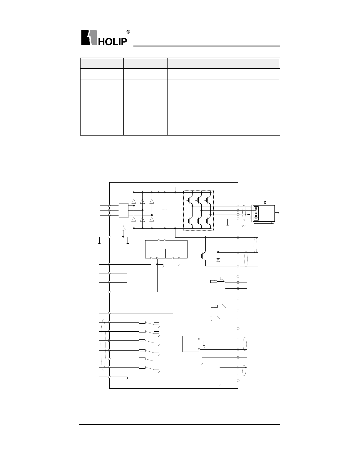
3.3.5 Wiring
Basic Connection Diagram of HLP-A100 series inverter:
Symbol Description Specication
COM Digital ground Isolated f rom internal GND;
Relay output
(K A-K B, FA-
FB-FC)
Relay output
1 、 Resistive load: 250VAC 3A/30VDC
3A;
2 、 Inductive load: 250VAC 0.2A /24VDC
0.1A(cosφ= 0.4);
RS+、 RS-
RS485 com m-
unication
Max baud rate: 115200bit/s;
10VD C
10Ma
24VD C
200Ma
24V +NpN+
0V +pNp+
24V +NpN+
0V +pNp+
24V +NpN+
0V +pNp+
24V +NpN+
0V +pNp+
24V +NpN+
0V +pNp+
24V +NpN+
0V +pNp+
RS485
I N te Rf a C e
pe
R
t
S
p Ow e R
INp ut
u
V
w
pe
+10V
VI
aI
GND
VD D
fOR
ReV
DI1
DO2
DI3
DI2
DI4
COM
+uDC
+uD C++BR
+BR
fa
fB
fC
Ka
KB
RS+
RS+
GND
0+10VD C
+4+20Ma
0+10VD C
+4+20Ma
0+10VD C
+4+20Ma
D C B uS
B RaKe
R e SIStOR
RS485
C O M M uN ICa tION
R e la y 1
R e la y 2
M OtOR
2
1
3
JuM p e R
S w I tC h
RfI
RfI
S w I tC h
D CM
VOltaGe O up ut
VO
aO
4+20Ma
DO1
D IGIta l
INp ut
D IGIta l
O utp ut
t e RM IN al R e SIS tO R
S w I tC h M O D e
pOweR Supply
CuRRe Nt O uput
J u M p e R S w I tCh
Page 27

HLP-A100 Series Operating Manual
HLP-A10 0 Ser ies
- 20 -
Precautions for the main circuit wiring:
● Note: The drives of more than 30kW (including 30kW) do not have +BR
and –BR terminals.
● While wiring the sizes and specications of wires should be selected
and the wiring should be executed according to the electrical
engineering regulations to ensure the safety.
● It is better to use shielded wire or wire conduit for power cord and
ground the shielded layer or two ends of wire conduit.
● Be sure to install a circuit Breaker between the power supply and the
in put ter minals (R.S.T). (If using RCD, please choose B ty pe)
● Phase-shif ting capacitors, LC, RC noise f ilters etc, can never be
connected to the output terminals of the inverter.
● Please lower the inverter switching f requency when there is a longer
distance between the inverter and the motor.
● Drive ea r t h leakage cu r rent is greater more than 3.5 mA. According
to the requirments of IEC 61800-5-1 , must use the f ollowing ways to
enhance the protection of ground: minimum 10mm2 cross sectional
area of copper, or additional PE line, its cross sectional area and the
main power cable should be the same, must be separate grounded.
● Make sure reliable ground of the inverter in accordance with IEC
618 0 0 -5 -1.
● Please refer to 9.2 for the use of RFI SWITCH.
Page 28
HLP-A10 0 Ser ies
HLP-A100 Series Operating Manual
- 21 -
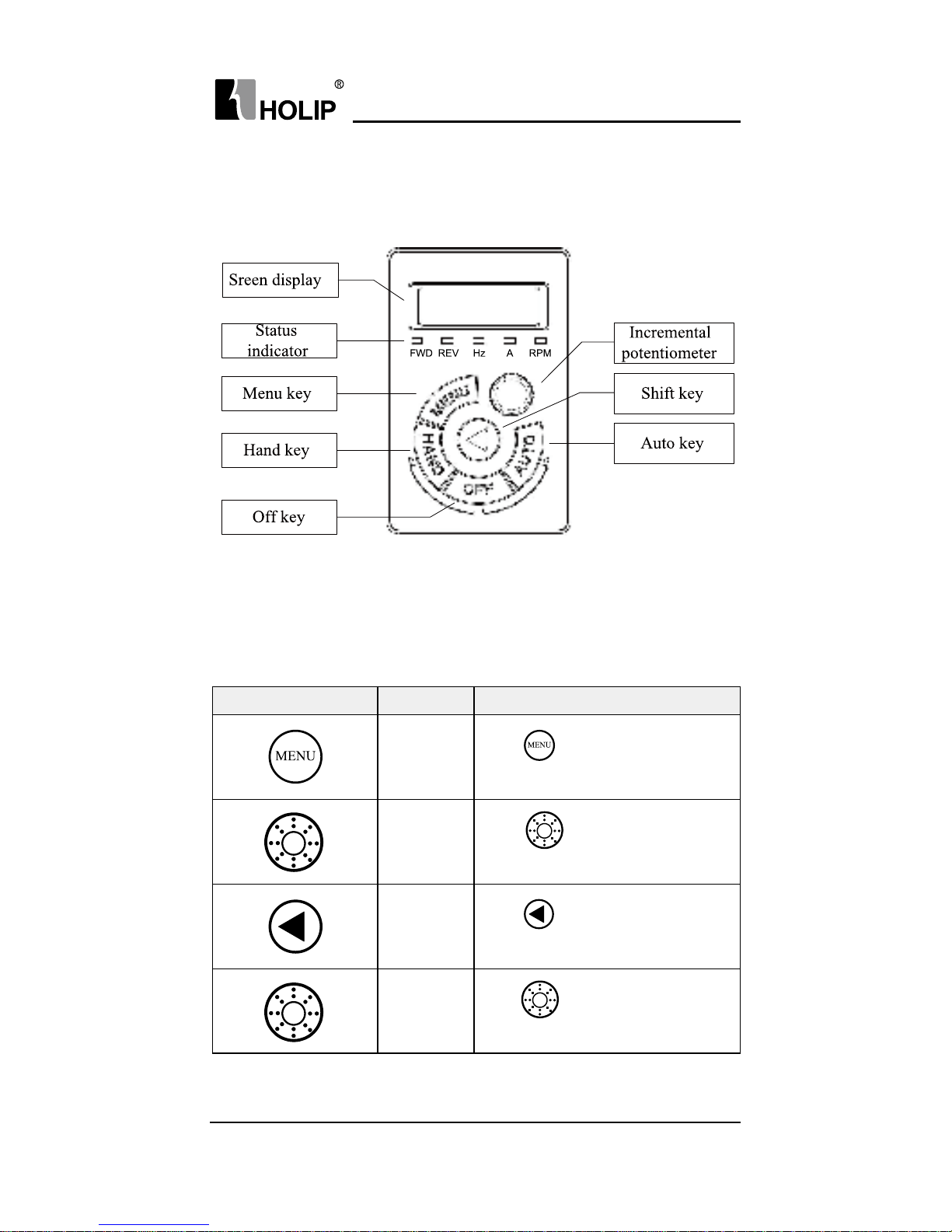
Key-press LCP Display Action Descr iption
C0 0.0 4
Press
key to display the rst
basic C00.03
C0 3.0 0
Tu r n
clockwise to select
pa ra meter grou p C03
C0 3.0 0
Press
key to shif t to f ractional
part
C 0 3.10
Tu r n
clockwise to select
p a r a m e t e r C0 3.10
Chapter 4 Operation and Display Interface
4.1 LCP Digital Operator
4.2 Quick to set parameters
4.2.1 Preset reference by LCP
Example: Set C03.10[0] to 20.5:
Page 29
HLP-A100 Series Operating Manual
HLP-A10 0 Ser ies
- 22 -
Key-press LCP Display Action Description
[0]
Press
key show the rst option
o f C 03.10
0000
Press
key to show the value of
the rst option of parameter C03.10
000.5
Tu r n
clockwise to change the
f ractional pa r t to 5
000.5
Press
key to shif t to integral
part
020.5
Press
key to change the
integ ral par t to 20
END
Press
key to accept the change
and save it as 20.5
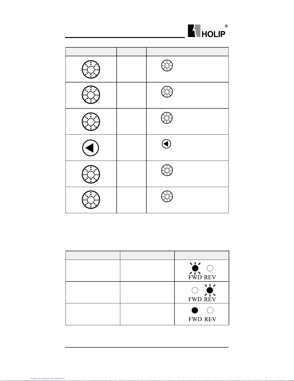
4.2.2 FWD/R EV Status
Conrm the direction of the motor according to the set value, as shown
in the following table:
Reference Running status Indicator Display
≥0 STOP
<
0 STOP
≥0 FWD
Page 30
HLP-A10 0 Ser ies
HLP-A100 Series Operating Manual
- 23 -
Reference Running status Indicator Display
≥0 REV
<
0 FWD
<
0 REV
Note: A ash light denotes the status coming, Light on indicates the current
state, and light off means not in this state.
Example 1: The f irst line of the table indicates the drive is stop and the
reference is greater than or equal to 0, means the dir ve at some
time in the f uture will r un forward.
Example 2: The fourth line of the table represents the cur rent drive is
reverse r unning, and the reference setting is greater than or
equal to 0, it means the drive at some time in the f uture will run
for ward.
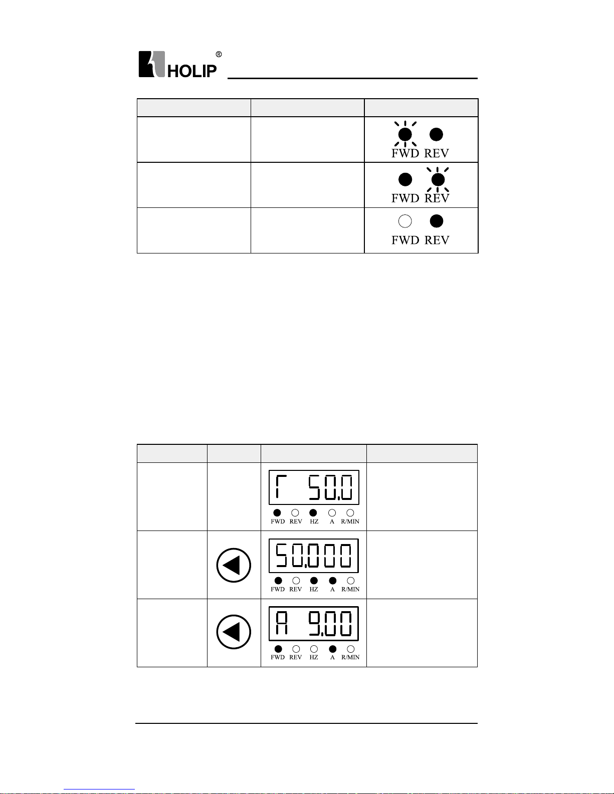
4.2.3 Data Read-outs
Display Items Key-press LCP Display Action Descr iption
Output
Frequency
Initial
interf ace
Show the output
f requency (C16.13)
is 50.0Hz, display
accuracy : 0.1
Reference (%)
Show the preset
reference (C16.01) is
50%, display accuracy:
0.0 01
Motor Current
Show the motor
current (C16.14) is
9.00A, display
accuracy: 0.01
Page 31

HLP-A100 Series Operating Manual
HLP-A10 0 Ser ies
- 24 -
Display Items Key-press LCP Display Action Descr iption
Mo t or Volt a ge
Show the motor
voltage (C16.12)
is 380.0V, display
accuracy: 0.1
Motor Speed
Show the motor speed
( C16. 05 ) i s 14 4 0 r p m ,
display accuracy:1
DC Volt age
Show the DC
v o l t a ge (C16 . 30 ) i s
540.0 V, d i s p la y
accuracy: 0.1
Inverter
temperat u re
Show the inverter
temperat u re
( p a r C16 . 34 ) i s 45℃,
display accuracy:1
Fee d ba ck
Value
Show the f eedback
value(C16.52) is 28.000,
display accuracy: 0.001
Counter A
Show value of counter
A is (C16.72) 65535,
display accuracy : 1
Counter B
Show counter B(C16.72)
is 65535, d ia pl a y
accuracy : 1
Analog in VI
Show analog in VI
(C16.62) is 10.00V,
display accuracy: 0.01
Page 32

HLP-A10 0 Ser ies
HLP-A100 Series Operating Manual
- 25 -
Key-press LCP Display Action Description
C0 0.0 4
Press
key to display the rst
basic C00.03.
C15. 0 0
Tu r n
clockwise to select par.
g r o u p N o. C15.
C15. 0 0
Press
to select pa rameter
nu m ber.
C15. 30
Tu r n
clockwise to select C15.30
Display Items Key-press LCP Display Action Descr iption
Analog in AI
Show Analog in AI
(C16.63) is 20.00mA,
display accuracy: 0.01
Pulse Input
Show pulse in put
(C16.68) is 50000Hz,
display accuracy:1
Pulse Output
Show pulse output
(C16.69) is 50000Hz,
display accuracy: 1
Note: Press key to cha nge the display items on control panel, however,
C00.33 must be activated (see C00.33).
4.2.4 View alarm record
If the drive trips, fault code will be showed to illust rate the reason, all the
trip record will be saved.
Page 33

HLP-A100 Series Operating Manual
HLP-A10 0 Ser ies
- 26 -
Key-press LCP Display Action Description
[0]
Press
to show the rst option
of C15.30
**
Press
to show the rst fault
record.
[1]
Press
to show the second f ault
record, it can display up to ten recent
fault records in t urn.
Key-press LCP Display Action Description
C0 0.03
Press
to display the rst basic
pa r a m e te r C 0 0.0 3.
C16 .0 0
Tu r n
clockwise to select Par.
g r o u p N o. C16
C16 .0 0 Press
to select pa r ame t er No.
C16 .01 Press
select C16.01
0
Tu r n
clock wise to nish browse
v a l u e o f C16 . 01.
4.2.5 View state parameter
View the status of input terminal, reference, feedback value, output
f requency, output current, output voltage, and the power etc.
Page 34

HLP-A10 0 Ser ies
HLP-A100 Series Operating Manual
- 27 -
Key-press LCP Display Action Description
C16 .6 0 Press
to select C16.60.
0000
Press
to view the value in
C16.60, 0100 indicates stat us of FOR
、
DI1 、 DI2 is 0, and stat us of REV is 1.
4.2.6 LED Display
Page 35

HLP-A100 Series Operating Manual
HLP-A10 0 Ser ies
- 28 -
Chapter 5 Parameter Overview
Item
Parameter
No.
Function
Descr iption
Setting range Unit
Def ault
setting
Page
No.
Parameter Group 00: Operation/Display
*C0 0.03
Regional
Settings
0: 50 Hz; 1: 60 Hz; 0 54
C0 0.0 4
Operating
State at
Power-u p
0: Resu me;1: Forced
stop ref erence=old;
2: Forced stop
reference=0;
1 54
*C0 0.06 G rid Ty pe 0 -132 * 55
C 0 0 .10 Active Set-up
1: Set-up1; 2: Set-up2;
9: Multi set-up;
1 55
C 0 0 .11 Edit Set-up 1: Set-up1; 2: Set-up2; 1 56
*C 0 0 .12 Link Set-up
0: N o t li n ke d ;
20: Li n ked;
20 56
C 0 0 . 31
Custom
Readout Min
Value
0.00-9999.00 0.00 56
C00.32
Custom
Readout Max
Value
0.00-9999.00 100.00 57
C0 0.33
LCP Display
Option
0-2047 0 57
C0 0.40
[H AND ON]
key on LCP
0: Disa bled;
1: E n a b l e d ;
1 57
C 0 0 .41
[OFF/ R ESET]
key on LCP
0: Disa ble A ll;
1: E n a b l e A l l ;
2: Enable Reset Only;
1 58
C0 0.42
[AUTO] key
on LCP
0: Disa bled;
1: E n a b l e d ;
1 58
*C 0 0 .51 Set-up Copy
0: No co py; 1: Copy
f rom set-up1; 2: Copy
f ro m se t-u p2; 9: Cop y
f rom factory set-up;
0 58
C0 0.60
Menu
Password
0: Disa bled;
1: E n a b l e d ;
0 58
C 01. 0 0
Conguration
Mode
0: Speed open loop;
3: Process closed loop;
4: To rq u e Op e n l o op;
0 59
Page 36

HLP-A10 0 Ser ies
HLP-A100 Series Operating Manual
- 29 -
Item
Parameter
No.
Function
Descr iption
Setting range Unit
Def ault
setting
Page
No.
Parameter Group01: Load/motor
*C 01.01
Motor Control
Pr i nciple
0: U/ F; 1: VCC+; 1 59
*C 01.0 3
Tor qu e
Characteristics
0: Constant torque;
1: Muta t ive; 3: Energy
optim;
0 59
*C 01.0 7
Application
Conguration
Mode
0: No Function;
1: Wobble Function;
2: Cascade Cont rol;
3: Winder Function;
0 60
*C 01. 2 0
Motor Power
[ kW ][ H P]
De p.on m o t or da ta kW * 60
*C01.22
Mo t or Volt a ge
(Um.n)
50~1000 V * 60
*C 01. 2 3
Motor
Frequency
(f m.n)
20~400 Hz * 61
*C 01. 2 4
Motor
Cu r rent(Im.n)
De p.on m o t or da ta A * 61
*C 01. 25
Motor
Nominal
Speed(nm.n)
100 ~9999 rpm * 61
*C 01. 29
Automatic
Motor
Adaptation
(AMA)
0: Of f ; 1: Enabled
Complete AMA;
2: Enable Reduced
AMA;
0 61
*C 01.3 0
Stator
Resista nce
(Rs)
De p.on m o t or da ta Ω * 62
*C 01.3 3
Stator
Leakage
Reactance
(XI)
De p.on m o t or da ta Ω * 62
*C 01.35
Main
Reactance
(X h)
De p.on m o t or da ta Ω * 62
*C 01.3 9 Motor poles 2 ~10 0 P 4 62
*C 01. 4 2
Motor Cable
Length
0 ~150 m 50 62
Page 37

HLP-A100 Series Operating Manual
HLP-A10 0 Ser ies
- 30 -
Item
Parameter
No.
Function
Descr iption
Setting range Unit
Def ault
setting
Page
No.
Parameter Group01: Load/motor
C 01. 50
Motor
Magnetisation
at Zero Speed
0 ~300 % 10 0 63
C 01. 52
Min Speed
Normal
Magnetising
[Hz]
0.0~10.0 Hz 0.0 63
C 01. 55
U/F Characteristic-U
0~999 V 63
C 01. 56
U/F Characte-
ristic-F
0~ 400 Hz 64
C 01. 6 0
Low Speed
Load
Compensation
0 ~19 9 % 10 0 64
C 01. 61
High Speed
Load
Compensation
0 ~19 9 % 10 0 65
C 01. 6 2
Slip
Compensation
- 4 00 ~399 % 10 0 65
C 01. 6 3
Slip
Compensation
Time
Constant
0.05~5.00 s 0 .10 66
C 01. 6 4
Resonance
Dampening
0~50 0 % 50 66
C 01. 65
Resonance
Dampening
Time
Constant
0.005~ 0.050 s 0.0 05 66
C 01.71 Sta r t Delay 0.0 ~10.0 s 0.0 66
C 01.7 2 Start Function
0: DC hold/delay
time; 2: Coast/Delay
ti me;
2 66
*C 01.7 3 Flying sta r t
0: Disa bled;
1: E n a b l e d ;
0 67
C 01. 8 0
Function at
Stop
0: Coast; 1: DC Hold; 0 67
Page 38

HLP-A10 0 Ser ies
HLP-A100 Series Operating Manual
- 31 -
Item
Parameter
No.
Function
Descr iption
Setting range Unit
Def ault
setting
Page
No.
C 01. 8 2
Min Speed for
Function at
Stop [Hz]
0.0~20.0 Hz 0.0 68
C 01. 9 0
Motor
Ther mal
Protection
0: No Protection;
1: Ther mister
War ning;
2: Termister Trip;
3: E T R w a r n i n g;
4: ETR trip;
0 68
*C 01.9 3
Thermister
Resou rce
0: None; 1: A na log
input VI; 6: Digital
input DI4;
0 68
Parameter Group 02: Brake Function
C02.0 0
DC Hold
Current
0 ~150 % 50 69
C 0 2 . 01
DC Brake
Current
0 ~150 % 50 69
C02.02
DC Braking
Time
0.0~ 60.0 s 10. 0 70
C02.0 4
DC Brake Cut
In Frequency
0.0~ 400.0 Hz 0.0 70
C02.08
Demagnatizing
Rate
0 ~10 0 % 10 0
C 0 2 .10
Bra ke
Function
0: Of f ; 1: Resist or
bra ke; 2: AC bra ke;
0 70
C 0 2 .11
Brake Resistor
(ohm)
De p.on m o t or da ta Ω * 70
C 0 2 .16
AC Brake,
Max current
0 ~150 % 10 0 70
C 0 2 .17
Over-voltage
Cont rol
0: Disa bled;
2: E na ble d;
0 71
C02.20
Release Brake
Current
0.00~100.00 A 0.00 71
C02.22
Activate
Bra ke Speed
[Hz]
0.0~ 400.0 Hz 0.0 71
C0 3.0 0
Reference
Ra nge
0: Min-Max; 1: -Max-
+Ma x;
0 72
C0 3.0 2
Minimum
Reference
-4999.000~ 4999.000 0.000 72
Page 39

HLP-A100 Series Operating Manual
HLP-A10 0 Ser ies
- 32 -
Item
Parameter
No.
Function
Descr iption
Setting range Unit
Def ault
setting
Page
No.
Parameter Group 03: Reference/Ramps
C03.03
Maximum
Reference
-4999.000~ 4999.000 50.000 72
C0 3.0 7
Main
reference
calculation
0: Preset reference +
Ref erence source 1,2
1: Preset ref erence
priority
0
C 0 3.10
Preset
Reference
-100.00~100.00 % 0.00 73
C 0 3 .11 Jog Speed [Hz] 0.0 ~ 400.0 Hz 5.0 74
C 0 3.12
Catch up/slow
Dow n Val u e
0.00~100.00 % 0.0 0 74
C 0 3.13
SpeedUp/
Dow n Val u e
0.01~50.00 Hz 0.10 74
C 0 3.14
Preset
Relative
Reference
-100.00~100.00 % 0.00 75
C 0 3.15
Reference
Resou rce 1
0: No function;
1: Analog input VI;
2: Analog Input AI;
8: P u ls e i n p u t;
11: Local bus ref;
21: L C P
potentiometer;
1 75
C 0 3.16
Reference
Resou rce 2
2 75
C 0 3.17
Reference
Resou rce 3
11 75
C 0 3.18
Relative
Scali ng
Reference
Resou rce
0 76
C 0 3.19
Save Speed
Up/Down
Value
0: No function;
1: Stopsa ve; 2: Power
dow n sa ve;
0 76
C0 3. 40 R a mp 1 Ty p e
0: Linear; 2: Sine2
ra m p;
0 76
C 03. 41
Ramp 1 Ramp
up Time
0.05~3600.00 s * 77
C0 3. 42
Ramp 1 Ramp
Down Time
0.05~3600.00 s * 78
C0 3. 50 Ra m p 2 Ty pe
0: Linear; 2: Sine2
ra m p;
0 78
Page 40

HLP-A10 0 Ser ies
HLP-A100 Series Operating Manual
- 33 -
Item
Parameter
No.
Function
Descr iption
Setting range Unit
Def ault
setting
Page
No.
Parameter Group 03: Reference/Ramps
C 0 3. 51
Ramp 2 Ramp
up Time
0.05~3600.00 s * 78
C0 3. 52
Ramp 2
Ramp down
Time
0.05~3600.00 s * 79
C0 3.6 0 Ra mp 3 Ty pe
0: Linear; 2: Sine2
ra m p;
0 79
C 03. 61
Ramp 3 Ramp
up Time
0.05~3600.00 s * 79
C0 3.6 2
Ramp 3 Ramp
dow n Time
0.05~3600.00 s * 79
C0 3.70 Ramp 4 Type
0: Linear; 2: Sine2
ra m p;
0 80
C 0 3.71
Ramp 4 Ramp
up Time
0.05~3600.00 s * 80
C0 3.72
Ramp 4
Ramp down
Time
0.05~3600.00 s * 80
C0 3.80
Jog Ramp
Time
0.05~3600.00 s * 80
C 03.81
Quick Stop
Ramp Time
0.05~3600.00 s * 80
Parameter Group 04: Limits/War nings
*C 0 4.10
Motor Speed
Direction
0: Clockwise;
1: Counterclock wise;
2: Bo t h;
2 81
*C 0 4.12
Motor Speed
Low Limit
[Hz]
0.0~ 400.0 Hz 0.0 81
*C 0 4.14
Motor Speed
High Limit
[Hz]
0.0~ 400.0 Hz 65.0 81
C 0 4.18 Cu r rent Limit 0~300 % 150 81
*C 0 4.19
Max. Output
Frenquency
0.0~ 400.0 Hz 65.0 82
C 0 4. 21
Max Output
Frequency
Resou rce
0 ~21 1
Page 41

HLP-A100 Series Operating Manual
HLP-A10 0 Ser ies
- 34 -
Item
Parameter
No.
Function
Descr iption
Setting range Unit
Def ault
setting
Page
No.
Parameter Group 04: Limits/War nings
C0 4.30
Motor
Feedback Loss
f unction
0: No function;
1: Freeze output;
3: Jog; 4: Max. Speed;
5: Stop and trip;
11: Switch to open
loo p;
4 82
C 0 4 . 31
Motor
Fee d ba ck
Speed Er ror
0~600 rpm 300 82
C04.32
Motor
Feedback Loss
Timeout
0.00~ 60.00 s 0.05 82
C0 4.50
War ning
Cur rent Low
0.00~ I ma x A 0.00 83
C 0 4 .51
War ning
Cu r rent High
0.00~ I ma x A 83
C0 4.52
War ning
Speed Low
0.0~ 400.0 Hz 0.0 83
C04.53
War ning
Speed High
0.1~ 400.0 Hz 65.0 83
C0 4.54
War ning
Reference
Low
-4999.000~ 4999.000 0.000 83
C0 4.55
War ning
Reference
High
-4999.000~ 4999.000 50.000 84
C0 4.56
War ning
Fee d ba ck Low
-4999.000~ 4999.000 0.000 84
C04.57
War ning
Fee d ba ck
High
-4999.000~ 4999.000 50.000 84
*C0 4.58
Missi ng
Motor Phase
Function
0: Of f ; 1: On; 1 84
C 0 4.61
Bypass Speed
From [Hz]
0.0~ 400.0 Hz 0.0 84
C0 4.63
Bypass Speed
To [H Z]
0.0~ 400.0 Hz 0.0 85
Page 42

HLP-A10 0 Ser ies
HLP-A100 Series Operating Manual
- 35 -
Item
Parameter
No.
Function
Descr iption
Setting range Unit
Def ault
setting
Page
No.
*C 05.0 2
Digital Output
DO Mode
0: PNP; 1: N PN; 0 86
C 0 5.10
Te r mi na l FOR
Digital Input
0: N o ope ra tion;
1: Reset; 2: Coast
i n v e r se ; 3: C o a s t a n d
reset inverse;
4: Quick stop inverse;
5: D C - b r a ke i n v e r s e;
6: Stop inverse;
8: St a rt; 9: Latched
star t; 10: Reversing;
11: Start reversing;
12: Enable star t
f o r w a r d ; 13: E n a bl e
star t reverse; 14: Jog;
15: Preset ref bit0;
16: Preset ref bit1;
17: Preset ref bit2;
18: Preset ref bit3;
19: Freeze reference;
20: Freeze output;
21: S p e e d u p;
22: Sp e ed dow n;
23: Set-up select;
28: Ca t ch u p; 29: Slow
down; 32: Pulse input
(only available with
terminal DI4 digital
i n p u t ) ; 34: R a mp
bit0; 35: Ramp bit1;
60: CounterA (up);
62: Reset counterA;
63: CounterB (up);
65: Reset counterB;
70: Wobble start
c o m m a n d ; 71: Wo b b l e
r e s et; 72: Wo b ble
initialization;
90: Low water level;
91: H i g h w a t e r l e v e l ;
8 86
C 0 5 .11
Te r mi na l
REV Digital
Input
10 86
C 0 5.12
Te r m i n a l DI1
Dgital Input
15 86
C 0 5.13
Te r mi na l DI 2
Digital Input
16 86
C 0 5.14
Te r mi na l DI3
Digital Input
17 86
Page 43

HLP-A100 Series Operating Manual
HLP-A10 0 Ser ies
- 36 -
Item
Parameter
No.
Function
Descr iption
Setting range Unit
Def ault
setting
Page
No.
C 0 5.15
Te r mi na l DI4
Digital or
Pulse Input
92: Scarcity water
level; 93: Over r un
water level;
18 86
Parameter Group 05: Digital In/Out
C05.30
Te r mi na l
D O1 D ig i t a l
Output
0: N o ope ra tion;
1: Control ready;
2: D r ive rea d y;
3: D r i v e r e a d y /
Remote control;
4: E na ble / N o
w a r n i n g; 5: D r iv e
running; 6: Running
/ No wa r ning;
7: Run in rang/ No
warning; 8: Run on
ref /No wa r ni ng;
9: Ala r m; 10: A lar m
or Warning; 12: Out
of cur rent ra ng;
13: Below current,
low; 14: Above
current,high; 15: Out
of f req uency rang;
16: Below f requency,
low; 17: Above
f re q uency, high;
18: Out of feedback
r a ng ; 19: Be l o w f e e d
back, low;
20: Above feedback,
high; 21: Thermal
warning; 22: Ready,
no t her mal wa r n i ng;
23: Remote ready, no
ther mal wa rn i ng;2 4:
R e a d y, v ol t ag e ok ; 25:
Reverse;
26: Bus ok; 28: Br ake,
no brake warning;
29: Br a ke rea d y, no
fault; 30: Brake fault
(IGBT); 32: Mech
br a ke cont rol;
0 88
C 0 5. 31
Te r mi na l
DO2 Digital
Output
0 88
Page 44

HLP-A10 0 Ser ies
HLP-A100 Series Operating Manual
- 37 -
Item
Parameter
No.
Function
Descr iption
Setting range Unit
Def ault
setting
Page
No.
Parameter Group 05: Digital In/Out
C05.4 0
Relay
Function
(K A-K B,FA-
FB 、 FB-FC)
36: Control word bit
11; 37: Control word
bit12; 40: Out of
ref erence rang;
41: Below ref, low;
42: Above ref , high;
51: Local ref , active;
52: Re mo t e r ef ,
active; 53: No alarm;
54: Start command
active; 55: Running
reverse; 56: Drive in
ha n d mod e;
57: D r iv e i n a u to
mod e;
60-63: Comparator
0-3; 70~73: Logic r ule
0-3; 80: SLC digital
output 1;
81: S L C d i g i t a l
output2; 82: SLC
relay 1; 83: SLC relay
2; 84: SL C di g it a l
output 3; 85: SLC
digital output 4;
90: Upto wobble
limit; 91: Upto wobble
ref .; 100: Start pu mp1;
101: Star t pump2;
102: Below water
level, low; 103: Above
water level, high;
104: Low water
w a r n i n g ; 10 5: H ig h
water warning;
106: Low voltage
w a r n i n g ; 10 7: O v e r
voltage war ni ng;
108: sl e e p;
5,9 88
Page 45

HLP-A100 Series Operating Manual
HLP-A10 0 Ser ies
- 38 -
Item
Parameter
No.
Function
Descr iption
Setting range Unit
Def ault
setting
Page
No.
Parameter Group 05: Digital In/Out
C05.55
Te r mi na l
DI4 Low
Frequency
0.020~49.999
KHz
0.020 91
C05.56
Te r mi na l
DI4 High
Frequency
0.021~50.0 00
KHz
50.000 91
C05.57
Te r mi na l DI4
Low Ref./
Feed b. Va l ue
-4999.000~ 4999.000 0.000 91
C05.58
Te r mi na l DI4
High Ref./
Fe e d b.V a l u e
-4999.000~ 4999.000 50.000 92
C05.59
Te r mi na l DI4
Filter Time
Constant
1~1000 ms 10 0 92
C05.60
Te r m i na l DO1
Pulse Output
Va r ia ble
0: Dgital output;
10: Output frequency;
11: Reference;
12: Feedback;
13: Motor current;
16: Power; 17: Speed;
18: Motor voltage;
20: Bus con t rol;
21: P u l s e i n p u t ;
22: Terminal VI
input; 23: Terminal
AI input;
0 92
C 05. 61
Pulse Output
Min Freq
0.020~49.999
KHz
0.020 93
C05.62
Pulse Output
Max Freq
0.021~50.0 00
KHz
50.000 93
C05.63
Pulse Output
Mi n Scale
0.00~200.00 % 0.00 93
C05.6 4
Pulse Output
Max Scale
0.00~200.00 % 100.00 93
C06.00
Live Zero
Timeout Time
1~ 9 9 s 10 94
Page 46

HLP-A10 0 Ser ies
HLP-A100 Series Operating Manual
- 39 -
Item
Parameter
No.
Function
Descr iption
Setting range Unit
Def ault
setting
Page
No.
Parameter Group 05: Digital In/Out
C 0 6.01
Live Zero
Timeout
Function
0: Of f ; 1: Freeze
out put; 2: Stop;
3: Joggi ng; 4: Max.
speed; 5: Stop and
Tr i p;
0 94
C 0 6.10
Te r mi na l V I
Low Volt a ge
0.0 0 ~ 9.9 9 V 0.07 95
C 0 6 .11
Te r mi na l V I
High Volt age
0.10 ~10 . 0 0 V 10 . 0 0 95
C 0 6.12
Te r mi na l V I
Low Current
0.0 0 ~19.99 mA 0 .14 95
C 0 6.13
Te r mi na l V I
High cur rent
0.01~20.00 mA 20.00 95
C 0 6.14
Te r mi na l V I
Low Ref./
Fe e d b.V a l u e
-4999.000~ 4999.000 0.000 95
C 0 6.15
Te r mi na l V I
High Ref./
Fe e d b.V a l u e
-4999.000~ 4999.000 50.000 96
C 0 6.16
Te r mi na l V I
Filter Time
Constant
0.01~10.00 s 0. 01 96
C 0 6 .18
Te r mi na l V I
Zero dead
band
0.00~20.0 0
V/
mA
0.00 96
C 0 6.19
Te r mi na l V I
Mode
0: Votage mode;
1: Current mode;
0 97
C06.20
Te r mi na l A I
Low Volt a ge
0.0 0 ~ 9.9 9 V 0.07 97
C 06 . 21
Te r mi na l A I
Hig h voltage
0.01~10.00 V 10. 0 0 97
C06.22
Te r mi na l A I
Low Current
0.0 0 ~19.99 mA 0 .14 97
C06.23
Te r mi na l A I
High Cur rent
0.01~20.00 mA 20.00 98
C06.24
Te r mi na l A I
Low Ref./
Fe e d b.V a l u e
-4999.000~ 4999.000 0.000 98
Page 47

HLP-A100 Series Operating Manual
HLP-A10 0 Ser ies
- 40 -
Item
Parameter
No.
Function
Descr iption
Setting range Unit
Def ault
setting
Page
No.
Parameter Group 05: Digital In/Out
C06.25
Te r mi na l A I
High Ref./
Fe e d b.V a l u e
-4999.000~ 4999.000 50.000 98
C06.26
Te r mi na l
AI Filter
Constant
0.01~10.00 s 0.01 98
C06.28
Te r mi na l A I
Zero dead
band
0.00~20.0 0
V/
mA
0.00 98
C06.29
Te r mi na l A I
Mode
0: Voltage mode;
1: Current mode;
1 99
C06.70
Te r mi na l VO
Mode
0: 0-20 m A;
1: 4-20m A; 3: 0-10V;
3 99
C 0 6.71
Te r mi na l
VOAnalog
Output
0: N o ope ra tion;
10: Output frequency;
11: Ref erence;
12: Feedback;
13: Motor current;
16: Power; 17: Speed;
18: Motor voltage;
20: Bus con t rol;
21: P u l s e i n p u t ;
22: Terminal VI;
2 3: Te r m i n a l A I;
0 99
C06.73
Te r mi na l VO
Output Min
Scale
0.00~200.00 % 0.0 0 10 0
C06.74
Te r mi na l VO
Output Max
Scale
0.00~200.00 % 100.00 10 0
C 0 6 .81
LCP Pot meter
Low Ref.
-4999.000~ 4999.000 0.000 10 0
C06.82
LCP Pot meter
High Ref.
-4999.000~ 4999.000 50.000 101
C06.90
Te r mi na l AO
Mode
0: 0 ~ 20 m A;
1: 4 ~ 2 0 m A ;
0 101
C 06 .91
Te r mi na l
AO A nalog
output
See also C06.71. 0 101
Page 48

HLP-A10 0 Ser ies
HLP-A100 Series Operating Manual
- 41 -
Item
Parameter
No.
Function
Descr iption
Setting range Unit
Def ault
setting
Page
No.
C06.93
Te r mi na l AO
Output Min
Scale
0.00~200.00 % 0.0 0 101
C06.9 4
Te r mia n l AO
Max Scale
0.00~200.00 % 100.00 10 2
Parameter Grou p07: Controllers
C 0 7.12
Tor qu e PI
Proportional
Gain
0~50 0 % 10 0
C 0 7.13
Tor qu e PI
Integration
Time
0.002 ~2 S 0.02
C 0 7.2 0
Process CL
Fee d ba ck
Resou rce
0: No Function;
1: A n a l o g i n V I ;
2: Analog in AI;
8: P u ls e i n p u t;
11: Local bus;
0 103
C 0 7.30
Process PI
Normal/
Inverse
Cont rol
0: Normal; 1: In verse 0 10 3
C 0 7. 31
Process PI
Anti Windup
0: Disa bled;
1: E n a b l e d ;
1 10 4
C 0 7.32
Process PI
Sta rt Speed
0.0~20 0.0 Hz 0.0 10 4
C 0 7.33
Process PI
Proportional
Gain
0.0~10.00 0.01 10 5
C 0 7.34
Process PI
Integ ral time
0.10~9999.00 s 9999.00 105
C 0 7.38
Process PI
Feed Forward
Factor
0~ 400 % 0 10 5
C 0 7.39
On Reference
Bandwidt h
0~200 % 5 10 5
C 07. 41
Process PI
Output Low
-10 0 -10 0 % 0 105
C 0 7.42
Process PI
Output High
-10 0 -10 0 % 10 0 10 6
Page 49

HLP-A100 Series Operating Manual
HLP-A10 0 Ser ies
- 42 -
Item
Parameter
No.
Function
Descr iption
Setting range Unit
Def ault
setting
Page
No.
Parameter Group 08: FC Port Settings
C 0 8.01 Cont rol Site
0: Digital and ctrl.
word; 1: Digital only;
2: Control Word
only;
0 10 6
C08.02
Control Word
Sou rce
0: None; 1: FC RS485; 1 10 6
C08.03
Control Word
Timeout Time
0.1~6500.0 s 1. 0 10 6
C08.0 4
Control Word
Timeout
Function
0: Of f ; 1: Freeze
out put; 2: Stop;
3: Joggi ng; 4: Max.
speed; 5: Stop and
t ri p;
0 10 6
C08.06
Reset Control
Word
Timeout
0: No Fu nction; 1: Do
Reset;
0 10 7
C08.30 Protocol
0: FC; 2: MODBUS
RTU; 6: MODBUS
ASCI I;
0 10 7
C 0 8. 31 Address
F C (1 ~1 2 6 ) ; M O D B U S
R T U (1~ 247 );
1 10 7
C08.32
FC Por t Baud
Rate
0: 2400; 1: 4800;
2: 9600; 3: 19200;
4: 38400; 5: Rese r ved;
6: R ese r ve d;
7: R es e r ve d;
8: R e se r ved ;
9: R es e r ved ;
2 10 7
C08.33 FC Por t Parit y
0: E v e n P a r i t y ,1S t o p
bit; 1: Odd Parity,1stop
bit; 2: No Parity,1Stop
bit; 3: No Parity,2
St o p bits;
0 10 8
C08.35
Minimum
Response
Delay
0.001~0.500 s 0.010 108
C08.36
Max.
Response
Delay
0.010 ~10.0 0 0 s 5.000 10 8
Page 50

HLP-A10 0 Ser ies
HLP-A100 Series Operating Manual
- 43 -
Item
Parameter
No.
Function
Descr iption
Setting range Unit
Def ault
setting
Page
No.
Parameter Group 08: FC Port Settings
C08.50
Coasting
Select
0: Digital input;
1: Bus; 2: Logic A ND;
3: Logic OR;
3 10 8
C 0 8.51
Quick Stop
Select
0: Digital input;
1: Bus; 2: Logic A ND;
3: Logic OR;
3 10 8
C08.52
DC Brake
Select
0: Digital input;
1: Bus; 2: Logic A ND;
3: Logic OR;
3 10 9
C08.53 Star t Select
0: Digital input;
1: Bus; 2: Logic A ND;
3: Logic OR;
3 10 9
C08.54
Reversing
Select
0: Digital input;
1: Bus; 2: Logic A ND;
3: Logic OR;
3 10 9
C08.55 Set-up Select
0: Digital input;
1: Bus; 2: Logic A ND;
3: Logic OR;
3 10 9
C08.56
Preset
Reference
Select
0: Digital input;
1: Bus; 2: Logic A ND;
3: Logic OR;
3 110
C08.94
Bu s Feed back
1
-32768~32767 0 11 0
Parameter Group 13: Simple PLC
C13.0 0
Sample PLC
Mode
0: Of f ; 1: Or der
execution; 2: Parallel
execution;
0 11 0
C13.01 St a r t Event 0 ~54 39 111
C13.0 2 Stop Event 0~54 40 11 2
C13.03
Reset Sample
PLC
0: Do not reset;
1: Reset Sample PLC;
0 11 2
C13.10
Comparator
Opera nd
0 ~ 31 0 11 3
C1 3.11
Comparator
Operator
0~2 1 11 3
C13.12
Comparator
Value
-9999.0~9999.0 0.0 11 4
C13. 2 0
SL Controller
Timer
0.0 ~36 0 0 s 0.0 11 4
Page 51

HLP-A100 Series Operating Manual
HLP-A10 0 Ser ies
- 44 -
Item
Parameter
No.
Function
Descr iption
Setting range Unit
Def ault
setting
Page
No.
Parameter Group 13: Simple PLC
C13.4 0
Logic Rule
Boolea n 1
0~64 0.0 11 4
C13.41
Logic Rule
Operator 1
0~8 0 114
C13.4 2
Logic Rule
Boolean 2
Same to C13.40 0 11 5
C13.4 3
Logic Rule
Operator 2
0~8 0 11 5
C13.4 4
Logic Rule
Boolean 3
Same to C13.40 0 11 6
C13. 51
SL Controller
Event
Same to C13.40 0 11 6
C13.52
SL Controller
Action
0~69 0 116
Parameter Group 14: Special Functions
C14.01
Switching
Frequency
2~6: 2kHz~6kHz;
7: 8k Hz; 8: 10 kHz;
9: 12k Hz; 10: 16 k Hz;
4 118
*C14.0 3
Over
modulation
0: Of f ; 1: On; 1 118
C14.0 8
Damping
Gain Factor
0~200 % 96 118
C14 .12
Function
at Mains
Imbalance
0: Trip; 1: Warning;
2: D i sa bl e d;
0 11 9
C14 .16
Low Volt a ge
Mode
0: Disabled; 1:
Ena ble;
0
C14. 2 0 Reset Mode
0: Ma n u al r es e t; 1~10:
Automatic reset x
1~10; 11: Automatic
r e s e t x 15;
12: Automatic reset x
20;
13: Innite auto reset;
0 11 9
C14 . 21
Automatic
Restart Time
0~600 s 10 11 9
C14. 2 2
Operation
Mode
0: Normal Operation;
2: Initialisation;
3: Backup user
settings;4: Recover
user settings;
0 11 9
Page 52

HLP-A10 0 Ser ies
HLP-A100 Series Operating Manual
- 45 -
Item
Parameter
No.
Function
Descr iption
Setting range Unit
Def ault
setting
Page
No.
Parameter Group 14: Special Functions
C14. 2 3 Trip Lock
0: Disable, Trip lock
fault reset do not
need power of f;
1: enable, Trip lock
fault reset need
power of f;
1
C14. 2 7
Action At
Inverter Fault
0: Tr i p; 1: Wa r ning; 0 120
C14.30
Current
Limit Cont rol,
Proportional
Gain
0~50 0 10 0
C14 . 31
Current
Limit Cont rol,
Integration
Time
0~2 0.02
C14.32
Current Limit
Cont r ol, Filter
Time
1~10 0 1
*C14. 4 0 VT Level 40-90 % 90 120
*C14 .41
AEO
Minimum
Magnetisation
40 ~75 % 66 120
C14.50
R FI Filter
Switch
0: Off 1:On
2:R ese r ved
1
*C14 .51
DC-Link
Vol t age
Compensation
0: Of f ; 1: On; 1 120
C14.52 Fa n Con t rol
0: Auto; 4:Run in
low temperature;
5-8: R es e r ve d;
0
*C14.55 Output Filter
0: Of f ; 1: Sine-Wave
Fi lt e r ; 3: Si n e -W a v e
Filter with feedback;
0 121
*C14.63
Min Switch
Frequency
2~6: 2kHz~6kHz;
7: 8k Hz; 8: 10 kHz;
9: 12k Hz; 10: 16 k Hz;
2 121
Page 53

HLP-A100 Series Operating Manual
HLP-A10 0 Ser ies
- 46 -
Item
Parameter
No.
Function
Descr iption
Setting range Unit
Def ault
setting
Page
No.
Parameter Group 15: Drive Information
C15. 0 0
Operating
Days
0~9999 d 121
C15. 01
Running
Hours
0~60000 h 121
C15. 0 2 KWh Counter 0 ~ 6 5535 121
C15. 03 P o w e r u p’s 0~21474836 47 122
C15. 0 4 O v e r Te m p’s 0 ~ 65535 122
C15. 05 Over Volt’s 0 ~ 65535 122
C15. 06
Reset KWh
Counter
0: Do not reset;
1: Reset Counter;
122
C15. 07
Reset
Running
Hours
Counter
0: Do not reset;
1: Reset Counter;
122
C15. 30
Fau l t Log:
Er ror Code
0 ~255 122
C15 . 31
In t er nal Fa u lt
Reason
-32767~32767 123
C15. 4 0 FC Ty pe View FC t y pe 12 3
C15.41 Power Sect ion
View power size of
the d rive
123
C15. 4 2 Volt a ge
View Mains Voltage
of the d r ive
123
C15. 43
Sof twa r e
Ver sion
View the sof tware
version
123
C15. 4 4
Orde r ed Type
Code
View the ordered
type code of the
drive
123
C15. 4 6
Frequency
converter
or de r i ng NO.
View f requency
converter ordering
NO.
123
C15. 47
Power Card
Or de r ing NO.
View power ca rd
orde ri n g No. of the
drive
124
C15. 48 LCP I D NO. View LCP ID NO. 124
C15. 49
Sof twa re ID
Control Card
View sof t ware ID
control card
124
Page 54

HLP-A10 0 Ser ies
HLP-A100 Series Operating Manual
- 47 -
Item
Parameter
No.
Function
Descr iption
Setting range Unit
Def ault
setting
Page
No.
C15. 50
Sof twa re ID
Power Card
View sof t ware ID
Power card
124
C15. 51
Frequency
Converter
Serial
Number
View f requency
converter No.
124
C15. 53
Power Card
Serial number
View power ca rd
serial number
124
C15. 92
Parameter
List
View parameter list
of the d r ive
124
Parameter Group 16: Data Readouts
C16 .0 0 Control Word 0 ~ 65535 125
C16 .01
Reference
[Unit]
-4999.000~ 4999.000 125
C16 .0 2 Reference % -200.0 ~20 0.0 % 126
C16 .0 3 Stat us Word 0 ~ 65535 126
C16 .0 4 Active Set-up 0~2 126
C16 .0 5
Motor Speed
[R PM]
0~9999 Hz 127
C16 .0 9
Custom
Readout
0.00~9999.00 127
C16 .10 Powe r[K W] 0.000~1000.000 kW 127
C1 6 .11 Power[h p] 0.000~1000.000 Hp 127
C16 .12 Motor Volt age 0.0 ~ 65535 V 127
C16 .13 Frequency 0.0~ 400.0 Hz 127
C16 .14
Motor
Current
0.0 0 ~ 655.35 A 127
C16 .15
Frequency
(%)
0.0~20 0.0 % 128
C16.18
Motor
Ther mal
0 ~10 0 % 128
C16 .30
DC Link
Vol t age
0 ~ 65535 V 128
C16 .3 4
Heat sink
Tem p.
0 ~255
℃
128
C16 .35
Inverter
Ther mal
0 ~255 % 128
C16 .36
Inv. Nom.
Current
0.0 0 ~ 655.35 A 128
Page 55

HLP-A100 Series Operating Manual
HLP-A10 0 Ser ies
- 48 -
Item
Parameter
No.
Function
Descr iption
Setting range Unit
Def ault
setting
Page
No.
Parameter Group 16: Data Readouts
C16 .37
Inv. Max.
Current
0.0 0 ~ 655.35 A 128
C16 .38
SLC
Controller
State
0 ~255 128
C16 .4 0
Wobble
Length
0.000~60.000 Km 129
C16.50
External
Reference
-200.0~200.0 % 129
C16.51
Pulse
Reference
-200.0~200.0 % 129
C16.52
Fee d ba ck #
[Unit]
-4999.000~ 4999.000 129
C16 .6 0 Digital In put 0 ~65535 129
C16 .61
Te r mi na l V I
Setting
0: 0-10V; 1: 0-20m A; 130
C16 .6 2
Analog Input
VI
0.000-20.000
V/
mA
130
C16 .6 3
Te r mi na l A I
Setting
0: 0-10V; 1: 0-20m A; 130
C16 .6 4
Analog Input
AI
0.000~20.000
V/
mA
130
C16 .6 5
Analog
Output AO
0.000~20.000
V/
mA
130
C16 .6 6
Digital Output
DO
0 ~255 130
C16 .6 7 Encoder Input -9999.000~9999.000
KHz
131
C16 .6 8
Pulse Input
DI4
0.020 ~50.000
KHz
131
C16 .6 9
Pulse Output
DO
0.020 ~50.000
KHz
131
C16 .71
Relay Output
[bin]
0 ~ 65535 131
C16 .7 2 Counter A 0 ~2147483647 131
C16 .7 3 Counter B 0~2147483647 131
C16 .7 8
Analog
Output AO
0.00~20.0 0 mA 131
C16 .86 FC Por t R EF -32768 ~32767 132
Page 56

HLP-A10 0 Ser ies
HLP-A100 Series Operating Manual
- 49 -
Item
Parameter
No.
Function
Descr iption
Setting range Unit
Def ault
setting
Page
No.
C16 .9 0 A la rm Word 0~0xFFFFFFFFUL 132
C16 .91
Ala r m Word
2
0~0xFFFFFFFFUL 133
C16 .9 2
War ning
Word
0~0x7FFFFFFFUL 133
C16 .9 3
War ning
Word 2
0~0x7FFFFFFFUL 134
Parameter Group 25: App. f unctions Cascade
C25.00 Cascade Mode
0: Normal cascade;
1: W a t e r l e v e l c o n t r o l ;
0 13 4
C25.03
Fixed Speed
Pump
Number
0~2 0 13 4
C 2 5.10
Multi Pressure
Select ion
0: Disa ble; 1: Ena ble; 0 134
C 2 5 .11 Present Time 0.0 0 ~ 2 3.59 h 0.00 134
C 2 5.12
Multi Pressure
Time
0.0 0 ~ 2 3.59 h 0.00 135
C25.2 0
Cascade Low
Frequency
0.000~400.000 Hz 20.000 135
C 25.21
Low
Frequency
Delay Time
0.0~3600.0 s 20.0 135
C25.25
Cascade High
Frequency
0.000~400.000 Hz 50.000 136
C25.26
High
Frequency
Delay Time
0.0~3600.0 s 20.0 136
C25.30
Low Pressure
War ning
Level
0.000~99.999 kg 3.000 136
C 25 . 31
Low Pressure
War ning
Delay Time
0.0~3600.0 s 10.0 136
C25.32
Recover y
Low Pressure
Level
0.000~99.999 kg 4.000 136
Page 57

HLP-A100 Series Operating Manual
HLP-A10 0 Ser ies
- 50 -
Item
Parameter
No.
Function
Descr iption
Setting range Unit
Def ault
setting
Page
No.
Parameter Group 25: App. f unctions Cascade
C25.33
Recover y
Low Pressure
Level Delay
Time
0.0~3600.0 s 10.0 137
C25.34
Over Pressure
War ning
Level
0.000~99.999 kg 7.000 137
C25.35
Over Pressure
War ning
Level Delay
Time
0.0~3600.0 s 10.0 137
C25.36
Recover y
High Pressure
Level
0.000~99.999 kg 5.000 137
C25.37
Recover y
High Pressure
Level Delay
Time
0.0~3600.0 s 10.0 137
C25.4 0
Pump
Interlock
Time
0.0~3600.0 s 5.0 138
C 25.41
Pump
Continuous
Run Time
0.0~3600.0 h 12.0 138
C25.50 Slee p Ti me 0: Disa ble; 1: Ena ble; 1 138
C 2 5. 51
Sleep Pressure
Level
0 ~150.0 % 95 138
C25.52
Sleep Pressure
Delay Time
0.0~300.0 s 20.0 139
C25.53
Sleep
Frequency
0.0~ 400.0 Hz 20.0 139
C25.54
Sleep
Frequency
Delay Time
0.0~300.0 s 20.0 139
C25.57 Awake Level 0.0~150.0 % 80 139
C25.60
Pu mp Ty pe
Select ion
0: Fe e d pu m p;
1: D r a i n p u m p ;
0 14 0
Page 58

HLP-A10 0 Ser ies
HLP-A100 Series Operating Manual
- 51 -
Item
Parameter
No.
Function
Descr iption
Setting range Unit
Def ault
setting
Page
No.
Parameter Group 25: App. f unctions Cascade
C 25. 61
Water Level
Sig n al Sou rce
0: Digital input;
1: Analog input VI;
2: A n alog i n pu t AI;
8: P u ls e i n p u t;
0 14 0
C25.62
Scarcit y
Water Level
0 ~10 0 % 0 141
C25.63
Low Water
Level
0 ~10 0 % 0 141
C25.6 4
Hig h Wa te r
Level
0 ~10 0 % 0 141
C25.65
Overr u n
Water Level
0 ~10 0 % 0 141
C25.66
Sta ndby
Pressure 1
0.000~99.999 kg 3.000 141
C25.67
Sta ndby
Pressure 2
0.000~99.999 kg 7.000 141
C25.68
Water Level
Dea d Ba nd
0 ~10 0 % 5 14 2
C25.69
Water Level
DI Delay
Time
0 ~360 0.0 s 20.0 14 2
C25.80
Ala r m Handle
Select ion
0: Stop all; 1: La g
pump 1 running;
2: L ag pu m p 2
r u n n i n g; 3: L a g
p um p 1
、
2 r un ning;
0 14 2
C30.0 0
Wobble Sta r t
Mode
0: Auto; 1: Ma nual; 0 143
C30.01
Dwell
Frequency
0.000~200.000 Hz 0.000 14 4
C30.0 2 Dwell Time 0.0 ~3600.0 s 0.0 14 4
C 30 .10
Centre
Frequency
Rate
0.000~30.000
Hz/
s
0.500 14 4
C 3 0 .11
Centre
Frequency
Low Limit
0.000~200.000 Hz 10.000 14 4
Page 59

HLP-A100 Series Operating Manual
HLP-A10 0 Ser ies
- 52 -
Item
Parameter
No.
Function
Descr iption
Setting range Unit
Def ault
setting
Page
No.
Parameter Group 30: Wobble Function
C 30 .1 2
Centre
Frequency
Mode
0: Fixed; 1: Auto
Dec r ea se;
0 14 4
C 30 .13
Delta
Frequency
Mode
0: R ela ti v e to Spee d
High; 1: Relative to
Centre Frequency;
0 145
C 30 .14
Delta
Frequency
Percentage
0 ~10 0 % 0 145
C 30 .15
Jump
Frequency
Percentage
0 ~10 0 % 0 145
C 30 .16
Wobble U p
Time
1.0 ~1000.0 s 10 145
C 30 .17
Wobble J u mp
Time
1~50 ms 1 145
C 30 .18
Wobble Dow n
Time
1.0 ~1000.0 s 10 145
C30.20
Random
Function
Mode
0: Disa ble; 1: Ena ble; 0 14 6
C 3 0 .21
Max.R a ndom
Ratio
-20~20 % 10 14 6
C30.22
Min Random
Ratio
-20~20 % -10 14 6
C30.30
Wobble
Length
Sou rce
0: Digital input;
7: E nc od e r i n p u t;
8: P u ls e i n p u t;
0 14 6
C 3 0 . 31
Count Per
Meter
0.01~600.00 1.0 0 14 6
C30.32
Setting
Length
0.000~60.000 Km 10.000 147
C30.33
Length Reach
Mode
0: No action; 1: Sto p; 0 14 7
C30.38
Wobble
Restore Mode
0: Operate at centre
f requency; 1: Operate
at preset f requency;
0 14 7
Page 60

HLP-A10 0 Ser ies
HLP-A100 Series Operating Manual
- 53 -
Note: Reference signed with “*”in parameter No. column means this parameter
can’t be modied when the motor is running. In factory setting column,
“*” means the default setting for this parameter is determined by the
d r ive t ype.
Item
Parameter
No.
Function
Descr iption
Setting range Unit
Def ault
setting
Page
No.
C30.39
Wobble Stage
Store
0: No function;
1: To store in stop and
power of f condition;
2:To store in power
off condition;
3: To store in stop
condition;
0 14 7
Page 61

HLP-A100 Series Operating Manual
HLP-A10 0 Ser ies
- 54 -
Chapter 6 Parameter Description
6.1 Parameter Group 00: Operation/Display
C00.0* Basic Settings
*C00.03 Function Description Range Unit Default Setting
Regional Settings 0 ~1 1
Option: [0] 50Hz, Motor frequency default value is 50 Hz, see C01.23;
[1] 60Hz, Motor frequency default value is 60 Hz, see C01.23;
Function: This parameter is used to select motor frequency default value
according to different regions;
Attention: This parameter can not be adjusted when motor is running. At
the same time changing this parameter may result in changes in
the value of the following parameters: C01.23、C01.25、C01.39
、
C01.56、C01.30、C01.33、C01.35.
C00.04 Functon Description Range Unit Default Setting
Operation State at
Power-up(Hand)
0~2 1
Option: [0] Resume, local reference is stored and used after power up;
[1] Forced stop, ref=old, local reference is stored and used after
power up;
[2] Forced stop, ref=0, local reference is set to 0;
Function: This parameter is used to control whether or not the frequency
converter should automatic running the motor when powering
up after a power down in Hand mode.
Description of choice: When select “[0]”, frequency converter starts
in same Hand mode roof state as when powered off; When
select“[1]”, frequency converter powers up in off state meaning
that motor is stopped after power up; When select“[2]”,
frequency converter powers up in off state meaning that motor
is stopped after power up. Local reference is set to 0. Thus motor
will not start running before local reference has been increased.
Attention: If LCP with potentiometer is mounted, reference is set
according to actual potentiometer value.
Page 62

HLP-A10 0 Ser ies
HLP-A100 Series Operating Manual
- 55 -
*C00.06 Function Description Range Unit Default Setting
Gr id Ty pe 0 ~132 *
Option: [0] 200-240V/50Hz/IT-Grid;
[1] 200-240V/50Hz/IT-Delta;
[2] 200-240V/50Hz;
[10] 380-440V/50Hz/IT-Grid;
[11] 380-440V/50Hz/IT-Delta;
[12] 380-440V/50Hz;
[20] 440-480V/50Hz/IT-Grid;
[21] 440-480V/50Hz/IT-Delta;
[22] 440-480V/50Hz;
[30] 525-600V/50Hz/IT-Grid;
[31] 525-600V/50Hz/IT-Delta;
[32] 525-600V/50Hz;
[100] 200-240V/60Hz/IT-Grid;
[101] 200-240V/60Hz/IT-Delt a;
[102] 200-240V/60Hz;
[110] 380-440V/60Hz/IT-Grid;
[111] 380 - 440V/60Hz / IT-Delt a ;
[112] 380-440V/60Hz;
[120] 440-480V/60Hz/IT-Grid;
[121] 440-480V/60Hz/IT-Delta;
[122] 440-480V/60Hz;
[130] 525-600V/60Hz/IT-Grid;
[131] 525-600V/60Hz/IT-Delta;
[132] 525-600V/60Hz;
Function:A correct type of Grid can optimize the output voltage/
frequency.
C0 0.10 Function Description Range Unit Default Setting
Active Set-up 1~9 1
Option: [1] Set-up 1;
[2] Set –up 2;
[9] Multi set-up;
Description of choice: HLP-B series inverter contains 2 set-ups: set-up1
and set-up 2, which can be switched via digital inputs or serial
communication commands. Binary code of the digital input
terminals correspond with set-ups as follows:
C00.1* Set-up Operations
Page 63

HLP-A100 Series Operating Manual
HLP-A10 0 Ser ies
- 56 -
Binar y bit0 Set-up No.
Te r m in a l St a te
0 1
1 2
Attention: The set-up can be switched between linked set-ups (See
C00.12) or when the motor is stop.
C00.11 Function Description Range Unit Default Setting
Edit Set-up 1~2 1
Option: [1] Set-up 1;
[2] Set-up 2;
Function: This parameter can be edited via LCP or serial communication
port.
*C00.12 Function Description Range Unit Default Setting
Link Set-ups 1~20 20
Option: [0] not linked, parameters between two set-ups can not change
each other while the motor is running;
[20] Linked, the link ensures synchronizing of the parameters
that can not be changed, while the motor is running. When this
is done, it is possible to shift from one set-up to the active set-up
selected.
Description of the choice: This parameter should be used in conjunction
with the active set-up. When C00.12 = 20, synchronize the “not
changeable during operation” parameters of the two set-ups.
When C00.10 = 9, the motor is running and switching the active
set-up is needed, if C00.12 = 20, switching can be achieved
while the motor is running; if C00.12 =0, set-ups can’t be
switched until the motor is stopped.
C00.31 Function Description Range Unit Default Setting
Custom Readout Min
Value
0~9999.00 0.00
Function: This parameter occurs at 0 Speed.
Description of the choice: This parameter allows the choice of the min.
value of the custom dened readout.
C0 0 . 3* L CP R ea dout
Page 64

HLP-A10 0 Ser ies
HLP-A100 Series Operating Manual
- 57 -
C00.33 Function Description Range Unit Default Setting
LCP Display Option 0~2047 0
Description of the choice: LCP will be fixed to display the output
frequency、reference and motor current. This parameter is
used to show 11 basic operating states of the inverter, each
parameter corresponds to a binary code: “1” means display
the item, “0” means does not display the item. For example,
if you want to display the states of the temperature and the
terminal VI on LCP. Transform the binary code to decimal digit,
C00.33=1×2
3
+1×27=136.
C00.32 Function Description Range Unit Default Setting
Custom Readout Max
Value
0~9999.00 100.00
Function: This parameter corresponds to settings in par. C04.14.
Description of the choice: This parameter sets the max value to be
shown when the speed of the motor has reached the set value for
C04.14.
Attention: C00.31 and C00.32 can adjust display of the custom readout
value, such as speed.
C00.40 Function Description Range Unit Default Setting
[HAND ON] Key on
LCP
0~1 1
Option: [0] Disabled: Hand-on key has no function;
[1] Enabled: Hand-on key is functional;
Description of the choice: The frequency converter can operate in the
following three mode: HAND、OFF/RESET and AUTO. When
running in Hand-on mode, the frequency converter is locally
operated and does not allow any remote control. By activating
hand a start signal is given.
C00.4* LCP K ey pad
Pulse output
Pulse Input
AI
VI
Counter
Counter
Feed back Va l u e
Tem pe ra t u r e
DC-voltage
Motor Speed
Motor Voltage
0 0 0 1 0 0 0 1 0 0 0
Page 65

HLP-A100 Series Operating Manual
HLP-A10 0 Ser ies
- 58 -
C00.41 Function Description Range Unit Default Setting
[OFF/RESET] Key on
LCP
0~2 1
Option: [0] Disabled, OFF/RESET key has no function;
[1] Enabled, OFF/RESET key stop signal and reset of any fault;
[2] Enabled reset only, reset only (fault), stop (off) function is
disabled;
Description of the choice: When OFF/RESET key is chosen, the
frequency converter stops with a normal stop ramp; it can only
be started by pressing either hand or auto key on the LCP.
C00.42 Function Description Range Unit Default Setting
[AUTO] Key on LCP 0 ~1 1
Option: [0] Disabled, Auto-on key has no function;
[1] Enabled, Auto-on key is functional;
Description of the choice: In auto-mode, the frequency can be remote
controlled (bus/digital).
*C00.51 Function Description Range Unit Default Setting
Set-up Copy 1~9 0
Option: [0] No copy;
[1] Copy from set-up 1;
[2] Copy from set-up 2;
[9] Copy from factory setting;
Function: Copy parameters settings from selected set-up to edited set-up
(C0.11).
Attention: When selected set-up is same to the edited set-up, copy
function doesn’t work; both control panel and parameter
database are locked while copying.
C00.5* Copy/Save
C00.60 Function Description Range Unit Default Setting
Menu Password 0~1
Option: [0] Disabled;
[1]Enabled, none of parameter can be changed except this;
Function: This feature used to prevent non-commissioning person to
C00.6* Protection
Page 66

HLP-A10 0 Ser ies
HLP-A100 Series Operating Manual
- 59 -
*C01.0 0 Function Description Range Unit Default Setting
Conguration Mode 0 ~3 0
Option: [0] Speed open loop,for general applications;
[3] Process closed loop,feedback signal is a process unit, such as:
pressure、temperature etc. When process closed loop is selected,
the motor can only run clockwise. For detailed parameter
settings, please refer to C07.3*.
[4] Torque Open loop, this mode is only effective in VVC+. For
detailed parameter settings, please refer to C07.1*.
Attention: If conguration mode is changed, C03.00, C03.02, C03.03 will
be restored to factory setting.
*C01.01 Function Description Range Unit Default Setting
Control Principle 0~1 1
Option: [0] V/F, used for parallel connected motors or special motors, V/
F settings are set in C01.55 and C01.56 separately;
[1] VVC+, used on applications that needs torque compensation
at low frequency or higher requirements on control performance.
Description of choice: Before V/F or VVC+ control, perform AMA rst
to get correct motor data.
Attention: When V/F control mode is selected, slip compensation and
load compensation are invalid; When VVC+ control mode is
selected,it includes slip compensation and load compensation
itself.
*C01.03 Function Description Range Unit Default Setting
Torque Characteristics 0~3 0
Option: [0] Constant torque, used for constant torque load;
[1] Variable torque, used for variable torque load, such as fan
applications、centrifugal pump etc;
[3]Auto Energy optimization, see C14.41 AEO minimum
magnetisation.
C01.0* General Settings
change the parameter settings.
Attention: Main Menu Password function is only valid to LCP, not active
to local bus.
6.2 Parameter Group 01: Load and Motor
Page 67

HLP-A100 Series Operating Manual
HLP-A10 0 Ser ies
- 60 -
Function: Choose suitable torque characteristics, it is possible to run low
energy consuming, as well as high torque applications.
*C01.07 Function Description Range Unit Default Setting
Application
conguration Mode
0~3 0
Option: [0] No function;
[1] Wobble function,see parameter group C30.*;
[2] Cascade control,see parameter group C25.*;
[3] Winder function (reserved);
Function: This parameter enables a choice of a configuration setting
that fits different applications. Wobble function is only valid
under speed open loop, in other control mode, wobble function
will be automatically shut down. If wobble function is selected,
parameterC03.00 will be set to “0”.
*C01.20 Function Description Range Unit Default Setting
Motor Power Dep. Motor date KW *
Function: Select the KW value that corresponds to the rated power of the
motor.
Description of choice: Factory settings depend on the inverter size, there
is one or two undersize or one oversize in comparison with
factory setting.
Attention: Changing the value of this parameter affects the setting of
C01.22- C01.25 and C01.30-C01.35.
*C01.22 Function Description Range Unit Default Setting
Motor Vol t ag e 50~1000 V *
Function: Select a value that equals the nameplate data on the motor.
Description of choice: Default setting depends on the inverter size.
In this parameter group, enter correct motor nameplate data (power,
voltage, frequency, current and speed). And then run AMA to obtain the
best motor data which will be stored in C01.3*.
Attention: Data of Parameter group C01.2* can not be changed when
motor is running.
C01.2* Motor Date
Page 68

HLP-A10 0 Ser ies
HLP-A100 Series Operating Manual
- 61 -
*C01.23 Function Description Range Unit Default Setting
Motor Frequency 20~400 Hz *
Function: Enter the rated motor frequency from the nameplate data.
Description of the choice: Default setting depends on the inverter size.
Attention: Changing this parameter affects motor nominal speed set in
C01.25.
*C01.24 Function Description Range Unit Default Setting
Motor Current Dep. motor data A *
Function: Enter motor current value from nameplate data.
Description of the choice: Factory settings depend on the unit size.
*C01.25 Function Description Range Unit Default Setting
Motor Norminal Speed 100~9999 RPM *
Function: Enter the motor nominal speed value from the nameplate data.
Description of the choice: Factory setting depends on the unit size.
Attention: If motor frequency has been changed in C01.23, Nominal
Motor Speed will be affected.
*C01.29 Function Description Range Unit Default Setting
Automatic Motor
Adaption (AMA)
0~2 0
Option: [0] Disabled;
[1] Enable complete AMA, run complete AMA which will take
up a longer time;
[2] Enable reduced AMA, if LC lter is used between the motor
and the frequency converter;
Description of the choice: AMA can be used to obtain accurate motor
parameters, optimizing control performance.
Attention: If LC filter is connected between motor and the frequency
converter, only reduced AMA can be carried out, and can’t test
the symmetry of the motor and whether there are phase losses
in the drive. For the best possible adaptation of the frequency
converter, it is recommended to run AMA on a cold motor. This
function is disabled when the motor is running.
Page 69

HLP-A100 Series Operating Manual
HLP-A10 0 Ser ies
- 62 -
*C01.35 Function Description Range Unit Default Setting
Main Reactance(Hh) Dep.motor data Ω *
*C01.30 Function Description Range Unit Default Setting
Stator resistance(R
S
) Dep.motor data Ω *
Function: Set stator resistance value. Enter the value from a motor data
sheet or perform an AMA on a cold motor.
Description of the choice: Depending on motor data.
*C01.39 Function Description Range Unit Default Setting
Motor Poles 2~100 P 4
Function: Enter the motor poles from the nameplate data.
Description of the choice: Depending on motor data.
*C01.42 Function Description Range Unit Default Setting
Motor Cable Length 0 ~150 m 50
Function: Enter the motor cable length connected between the motor and
the frequency converter.
Description of the choice: Set correct cable length can suppress noises
resulted from the motor.
*C01.33 Function Description Range Unit Default Setting
Stator leakage
reactance
Dep.motor data Ω *
Function: Set stator leakage reactance value. Enter the value from a
motor data sheet or perform an AMA on a cold motor. The
default setting is calculated by the drive from motor nameplate
data.
Description of the choice: Depending on motor data.
Function: Set the main reactance value. Enter the value from a motor
data sheet or perform an AMA on a cold motor. The default
setting is calculated by the drive from motor nameplate data.
Description of the choice: Depending on motor data.
This parameter can not be changed while motor is running.
C01.3* Adv.Motor Data
C01. 4* M o t or Ca bl e Le ng th
Page 70

HLP-A10 0 Ser ies
HLP-A100 Series Operating Manual
- 63 -
C01.55 Function Description Range Unit Default Setting
V/F Characteristic-V 0~999.9 V 0/ Vn
Function: This parameter is an array parameter [0-5], used for setting
voltage [V0-V5] at each frequency point to manually form a V/
F characteristic matching motor. Frequency points are dened in
par. C01.56, V/F characteristics - F.
Description of choice: This parameter is only functional when par.
C01.01, Motor Control Principle is set to V/F [0].
Attention: V0 factory setting is set to 0V, and U1-U5 factory setting is set
to Un (motor rated voltage) .
C01.50 Function Description Range Unit Default Setting
Motor Magnetisation
at zero speed
0~300 % 100
Function: Enter a percentage value of the rated magnetizing current.
Description of the choice: Use this par. with par. 1-52 to obtain a different
thermal load on the motor when running at low speed.
Attention: If the setting is too low; the torque on the motor may be
reduced.
C01.52 Function Description Range Unit Default Setting
Min Speed Normal
Magnetizing
0.0~10.0 Hz 100
Function: Set the required frequency for normal magnetising current.
Use this par. along with par. 1-50.
Attention: If the frequency is set lower than the motor slip frequency, par.
C01.50 is inactive.
C01.5* Load Indep.Setting
Page 71

HLP-A100 Series Operating Manual
HLP-A10 0 Ser ies
- 64 -
C01.56 Function Description Range Unit Default Setting
V/F Characteristic-F 0~400 Hz 0/Fn
Function: This parameter is an array parameter [0-5], used for setting
frequency points [F0-F5] to manually form a V/F characteristic
matching motor. Voltage at each point is dened in par. C01.55,
V/F Characteristic - V.
Description of choice: This parameter is only functional when par. C01.01
Motor Control Principle is set to V/F [0].
Attention: F0 factory setting is set to 0Hz, and F1-F5 factory setting is
set to Fn (Motor rated frequency); for par. C01.56 the following
applies F0=0 and F1≤F2≤F3≤F4≤F5.
Simplify V/F characteristic by merging 2 or more points (voltages
and frequencies), which respectively are set equal.
The slope (ratio of V/F) after point (F5,V5) must be equal to the
slope between point (F5, V5) and the previous point.
Fig. 6.1 V/F characteristic diagram
C01.6* Load Depen.Setting
C01.60 Function Description Range Unit Default Setting
Low Speed Load
Compensation
0~199 % 100
Function: Use this parameter to compensate voltage in relation to load
when motor runs at low speed.
Description of choice: Enter a percentage value to compensate voltage
when motor needs running at low speed. Change-over point is
automatically calculated based on motor size.
Page 72

HLP-A10 0 Ser ies
HLP-A100 Series Operating Manual
- 65 -
C01.62 Function Description Range Unit Default Setting
Slip Compensation -400~399 % 10 0
Function: Dynamically adjust the output frequency of the motor,
maintain the motor approaching a constant speed, and doesn’t
vary with load changes.
Description of Choice: This function is only active when par. C01.00,
Conguration Mode, is set to Speed Open Loop [0], and when
par. C01.01, Motor Control Principle, is set to VVC+ [1]. Slip
compensation is calculated automatically based on rated motor
speed, nM,N.
C01.61 Function Description Range Unit Default Setting
High Speed Load
Compensation
0~199 % 100
Function: Use this parameter to compensate voltage in relation to load
when motor runs at high speed.
Description of Choice: Enter a percentage value to compensate voltage
when motor needs running at low speed. Change-over point is
automatically calculated based on motor size.
Page 73

HLP-A100 Series Operating Manual
HLP-A10 0 Ser ies
- 66 -
C01.63 Function Description Range Unit Default Setting
Slip Compensation
Time Constant
0.05~5.00 S 0.10
Function: Enter the slip compensation reaction speed. A high value
results in slow reaction, and a low value results in quick reaction.
If low-frequency resonance problems arise, use a longer time
setting.
C01.64 Function Description Range Unit Default Setting
Resonance Dampening 0~500 % 50
Function: High-frequency resonance problems between motor and the
frequency converter can be eliminated by setting this parameter.
C01.65 Function Description Range Unit Default Setting
Resonance Dampening
Time constant
0.005~0.050 S 0.005
Description of choice: Choose a time constant that provides the best
dampening.
C01.7* Start Adjustments
C01.71 Function Description Range Unit Default Setting
Start Delay 0.0~10.0 S 0.0
Function: This parameter enables a delay of the starting time. The
frequency converter begins with the start function selected in
par. 1-72. Set the start delay time until acceleration is to begin.
Attention: Setting start delay to 0.0 sec. disables Start Function, [C01.72],
when start command is given.
C01.72 Function Description Range Unit Default Setting
Start Function 0~2 2
Option: [0] DC Hold/delay time;
[2] Coast/delay time;
Function: Select [0], Motor is energized with DC holding current (par.
C02.00) during start delay time; Select [2], Motor is coasted
during start delay time (inverter off ).
Page 74

HLP-A10 0 Ser ies
HLP-A100 Series Operating Manual
- 67 -
C01.8* Stop Adjustments
C01.80 Function Description Range Unit Default Setting
Function at Stop 0~1 0
Option: [0] Coast, the inverter is off;
[1] DC Hold, the motor is energized with a DC current. See par.
C02.00 DC Hold Current for more information.
Function: Here it is possible to select the stop function according to
different applications.
*C01.73 Function Description Range Unit Default Setting
Flying Start 0~1 0
Option: [0] Disabled;
[1] Enabled;
Description of Choice: This function applies for the inertia load to restart
due to mains drop-out; If Clockwise[0] is selected(C04.10),
and no rotating motor is found, It is possible to use DC-brake
command to ramp down the motor speed to 0 rpm, and then start
the motor in the normal way; If Both directions [2](C04.10) is
selected, and no rotating motor is found, the drive will assume
the motor is stationary or in low-speed rotation, and then start
the motor in the normal way. When Flying start is enabled,
C01.71 (Start delay) and C01.72 (Start function) is invalid.
Warning: This function is not suitable for hoisting applications.
Page 75

HLP-A100 Series Operating Manual
HLP-A10 0 Ser ies
- 68 -
Description of Choice: This f unction is active in the following situations:
Stop command is given and output speed is ramped down to Min.
Speed for activating Functions at Stop; Start command is removed
(standby), and output speed is ramped down to Min. Speed for
activating Functions at Stop; DC-brake command is given, and lasts
out of DC-brake delay time.
C01.82 Function Description Range Unit Default Setting
Min Speed for Function
at Stop [Hz]
0.0~20.0 Hz 0.0
Function: Set the output frequency at which to activate par. C01.80
Function at stop.
C01.90 Function Description Range Unit Default Setting
Motor Thermal
Protection
0~4 0
Option: [0] No protection;
[1] Thermistor warning, A thermistor connected to either
digital or analog input gives a warning if upper limit of motor
temperature range is exceeded, (see par. C01.93, Thermistor
Resource).
[2] Thermistor trip, A thermistor connected to either digital or
analog input gives an alarm and makes the frequency converter
trip if upper limit of motor temperature range is exceeded, (see
par. C01.93, Thermistor Resource).
[3] ETR warning, If calculated upper limit of motor temperature
range is exceeded, a warning occurs.
[4] ETR trip, If calculated upper limit of motor temperature range
is exceeded, an alarm occurs and frequency converter trips.
Function: Running ETR (Electronic Terminal Relay) function, motor
temperature is calculated based on frequency, speed and time.
Holip recommends performing the ETR function, if a thermistor
is not present.
C01.9* Motor Temperature
*C01.93 Function Description Range Unit Default Setting
Thermistor Resource 0~6 0
Option: [0] None;
[1] Analog input VI, Connect thermistor to analog input terminal
Page 76

HLP-A10 0 Ser ies
HLP-A100 Series Operating Manual
- 69 -
VI;
[6] Digital input DI4, Connect thermistor to digital input
terminal DI4;
Function: Select the thermistor input terminal.
Attention: Analog input can’t be selected for other purpose when selected
as thermistor resource.
Digital input DI4 can’t be selected for other purpose when selected
as thermistor resource.
Thermistor specications:
Input signal type Vol tage Su ppl y Termistor threshold
Digital 10 V <0.8kΩ , >2.9kΩ
Analog 10 V <0.8kΩ , >2.9kΩ
C02.00 Function Description Range Unit Default Setting
DC Hold Current 0 ~150 % 50
Function: This parameter either holds the motor (holding torque) or
preheats the motor. This parameter is active if DC Hold has been
selected in either C01.72 start function or C01.80 Function at
Stop.
Description of Choice: Enter a value for holding current as a percentage
of the rated motor current set in par. C01.24 Motor Current.
100% DC holding current corresponds to IM,N.
Attention: Avoid 100% current too long as it may overheat the motor.
C02.01 Function Description Range Unit Default Setting
DC Brake Current 0~150 % 50
Function: This parameter is used for setting the DC brake currents that is
set as a percentage value of the rated motor current IM, N set in
C01.24.
Description of Choice: Parameters related to the DC brake current are as
follows:
DC-brake command, see C05.1* choice (5);
DC brake cut in speed, see C02.04;
C02.0* DC -Brake
6.3 Parameter Group 02: Brakes
Page 77

HLP-A100 Series Operating Manual
HLP-A10 0 Ser ies
- 70 -
C02.02 Function Description Range Unit Default Setting
DC Braking Time 0.0~60.0 S 10.0
Function: This parameter denes DC brake current (C02.01) time during
which DC-brake current is applied to the motor.
Function: This parameter is for setting the DC brake cut in speed at
which the DC braking current (par.02.01) is to be actived, in
connection with a stop command. When set to 0 the function is
off.
Function: Set motor demagnatizing rate.
C02.04 Function Description Range Unit Default Setting
DC Brake Cut in
Speed
0.0~ 400.0 Hz 0.0
C02.08 Function Description Range Unit Default Setting
Demagnatizing Rate 0~100 % 100
C02.10 Function Description Range Unit Default Setting
Brake Function 0 ~2 0
Option: [0] off;
[1] Resistor brake, use the resistor brake to consume surplus
energy resulting from motor braking, and prevent the frequency
converter to trip due to over-voltage in the intermediate circuit;
[2] AC brake, dissipate surplus energy in the motor core, and
prevent the energy back into frequency converter causing trips.
It is important to keep in mind that frequent use of this function
will cause a sharp increase in motor temperature.
Attention: Resistor brake is only functional when the frequency converter
build-in braking unit or external braking unit must be installed.
C02.11 Function Description Range Unit Default Setting
Brake Resistor (ohm) 5~65535 Ω *
Function: Set brake resistor value.
C02 .16 Function Description Range Unit Default Setting
AC Brake, Max Current 0~150 % 100
C02.1* Brake Energ y Funct.
Page 78

HLP-A10 0 Ser ies
HLP-A100 Series Operating Manual
- 71 -
Function: Enter the maximum permissible current when using AC brake
to avoid overheating of motor windings. 100% equals motor
current set in C01.24.
C02.17 Function Description Range Unit Default Setting
Over-voltage Control 0~2 0
Option: [0] Disabled, The OVC is not active/required;
[2] Enabled, OVC is running;
Function: OVC is used to consume surplus energy by increasing the
output frequency. Select whether to enable OVC, which reduces
the risk of drive trip due to over voltage on the DC link caused
by generative power from load.
Attention: The OVC is not active/required if resistor brake has been
chosen in C02.01 (Brake Function).
C02.20 Function Description Range Unit Default Setting
Release Brake Current 0.00~100.0 A 0.00
Function: Set motor current at which mechanical brake is released. The
relay acts when motor speed is greater than settings in this
parameter.
Attention: If start delay time has passed, and motor current is below
Release brake current, frequency converter trips.
C02.22 Function Description Range Unit Default Setting
Activate Brake Speed 0.0~400.0 Hz 0.0
Function: The mechanical brake is activated when motor speed is less
than Activate Brake Speed.
Description of Choice: This feature occurs in the following situations:
● A start command is removed;
● A stop command is activated;
● Quick-stop is activated (Q-stop function is used);
C02.2* Mechanical Brake
For hoisting applications an electro-magnetic brake is required, brake
signal can be sent via the relay. The brake activates if f requency converter
trips or a coast command is given. Furthermore, it activates when the motor
speed is ramped down below the speed set in C02.22, Activate Brake Speed.
Page 79

HLP-A100 Series Operating Manual
HLP-A10 0 Ser ies
- 72 -
6.4 Parameter Group 03: Reference/Ramps
C03.0* Reference Limits
C03.00 Function Description Range Unit Default Setting
Reference Range 0 ~1 0
Option: [0] Min-Max, Reference set point ranges can have positive values
only.
[1] -Max~+Max, Ranges can have both positive and negative
values.
Function: Select the range of reference, only positive values are allowed
when conguration mode (C01.00) is set to Speed Closed Loop
[1] or Process Closed Loop [3].
C03.02 Function Description Range Unit
Default
Setting
Minmum Reference -4999.000~4999.000 0.000
Function: Enter value for Minimum Reference.
Description of Choice: The sum of all internal and external references is
clamped (limited) to the minimum reference value.
C03.03 Function Description Range Unit
Default
Setting
Maximum Reference -4999.000~4999.000 50.000
Function: Enter value for Maximum Reference.
Description of Choice: The sum of all internal and external references is
clamped (limited) to the maximum reference value.
Attention: The maximum reference can not be less than C03.02 (Minimum
Reference).
Page 80

HLP-A10 0 Ser ies
HLP-A100 Series Operating Manual
- 73 -
C03.07 Function Description Range Unit Default Setting
Actual reference
calculation 0~1 0
Option: [0] Preset reference + Reference source 1,2,3
[1] Preset reference priority
Description of Choice:
[0], Actual reference = Preset reference + Reference source 1,2,3
[1], When using preset reference 1-N, actual reference = preset
reference [1-N], else actual reference = preset reference [0] +
reference source 1,2
C03.10 Function Description Range Unit
Default
Setting
Preset Reference -100.00~100.00[16] % 0.00
C03.1** References
Function: This parameter is an array-16 to be used for presetting different
references.
Description of Choice: When C03.00 select “1”(-Min~Max), 100%= value
set in C03.03; When C03.00 select “0”(Min~Max), for example,
If C03.02 is set to “20” and C03.03 is set to 50, 0%=0 and 100
%
=
50; If C03.02 is set to “-70”, and C03.03 is set to 50, 0%=0
and 100%=70.
Each parameter set-up contains 16 preset references which are selectable
via digital terminals or local bus. See C05.1*.
Selection of preset ref erence indicates wit h a four-digital bina r y code. If
the f requency converter detects the corresponding terminals connected, then
the bit is “1”, otherwise, the bit is “0”. Digital input terminal
、
binary code and
the corresponding relationship between pre-set values as follows:
Page 81

HLP-A100 Series Operating Manual
HLP-A10 0 Ser ies
- 74 -
C03.11 Function Description Range Unit Default Setting
Jog Speed 0.0~400.0 Hz 5.0
Function: Jog frequency is a xed frequency that the drive supplies to the
motor after the jog function is actived. Please refer to C05.1*,
select [14].
Description of Choice: The frequency converter with the highest priority
will operate at jog speed when a variety of run command
activates. Removing the jog signal makes the frequency
converter run according to the selected configuration, this
parameter is set limited by C04.14.
C03.12 Function Description Range Unit Default Setting
Catch up/Slow down
Value
0.00~100.00 % 0.00
Function: This parameter enables the entry of a percentage value
(relative) which will to be either added to or deducted from the
actual reference.
Description of Choice: The Catch up/Slow down function is activated by
a digital input terminal (See C05.1*, choose [28]/ [29] ). If this
function is active, the catch up/slow down value will be added
Binar y
system
bit3 bit2 bi t1 bit0 Preset Reference
Te r mi na ls
State
0 0 0 0 0
0 0 0 1 1
0 0 1 0 2
0 0 1 1 3
0 1 0 0 4
0 1 0 1 5
0 1 1 0 6
0 1 1 1 7
1 0 0 0 8
1 0 0 1 9
1 0 1 0 10
1 0 1 1 11
1 1 0 0 12
1 1 0 1 13
1 1 1 0 14
1 1 1 1 15
Page 82

HLP-A10 0 Ser ies
HLP-A100 Series Operating Manual
- 75 -
C03.13 Function Description Range Unit Default Setting
Speed Up/Down Value 0.01~50.00 Hz 0.10
Function: Enter the Speed Up/Down value.
to the actual reference constituting new setting at which the
frequency converter is going to run, calculated as follows:
Total reference= reference ±reference × (Catch up/Slowdown
value)
If this function is inactive, the reference returns to its original value (the
actual reference).
For example: Set C05.12=28, C05.13=29, C03.12=30, assuming the
actual reference value is 20 Hz, when only DI1 is on, the output
frequency is 26 Hz, when only DI2 is connected, the output
frequency is14Hz, when both DI1 and DI2 are on, the output
frequency is 20Hz.
C03.14 Function Description Range Unit Default Setting
Preset Relative
Reference
-100.00~100.00 % 0.00
Function: Dene an adjustable Preset Relative Reference which is to be
added to the total reference as a percentage value of the actual
reference .
Total Reference=Actual Reference+Actual Reference * Preset Relative
Reference + Actual reference * Relative Scaling Reference
Example:
Min
Reference/
C0 3.0 2
Preset
Relative
Reference/
C 0 3.14
Relative
Scali ng
Reference
V I / C 0 3 .18 = 1
Preset
Reference/
C 0 3.10
Max
Reference/
C03.03
Output
Frequency
(Hz)
0 0% 10 V 20% 50 10 + 0 +10 = 20
0 10 % 8V 20% 50 10 +1+ 8 =19
0 20% 5V 20% 50 10 + 2 + 5 = 17
0 30% 3V 20% 50 10 +3+3=16
0 40% 0V 20% 50 10 + 4 + 0 =14
Page 83

HLP-A100 Series Operating Manual
HLP-A10 0 Ser ies
- 76 -
C03.15 Function Description Range Unit Default Setting
Reference Resource1 0~21 1
C03.16 Function Description Range Unit Default Setting
Reference Resource2 0~21 2
C03.17 Function Description Range Unit Default Setting
Reference Resource3 0~21 11
Option: [0] No f unction, no reference resource is dened;
[1] A nalog i n VI, use signals f rom Analog input VI as ref erence
resource, see C06.1*;
[2] Analog in AI, use signals from Analog input AI as reference
resource, see C06.2*;
[8] Pulse input, use signals f rom Pulse input (DI4) as ref erence
resource, see C05.5*;
[11] Local bus reference, use signals f rom Local bus ref erence as
ref erence resource, see C08.9;
[21] LCP potentiometer, use signals f rom LCP potentiometer as
ref erence resource, see C06.8*;
F u n c t i o n : C 03.15
、
C03.16 and C03.17 def ine up to three different reference
signals, the sum of which denes is the act ual reference.
C03.18 Function Description Range Unit Default Setting
Relative Scaling Ref. 0 ~21 0
Option: [0] No f unction: No relative scaling ref. resource is dened;
[1] Analog input VI, select analog input VI as relative scaling ref.
source, see C06.1*;
[2] Analog input AI, select analog input AI as relative scaling ref.
source, see pa r. C06.2*;
[8] Pulse input, select pulse input (DI4) as relative scaling ref. source,
se e p a r. C0 5.5*;
[11] Local bus reference, select local bus reference as relative scaling
ref. source, see par. C08.9*;
[21] LCP potentiometer, select LCP potentiometer as relative scaling
ref. source, see par. C06.8*;
Function: The Relative Scaling Ref. Resource can be set via Analog input
terminals
、
Local bus reference and LCP potentiometer.
Page 84

HLP-A10 0 Ser ies
HLP-A100 Series Operating Manual
- 77 -
C03.19 Function Description Range Unit Default Setting
Save Speed Up/Down Value 0~2 0
Option: [0] No Function;
[1] Stop Save;
[2] Powe r Dow n Save;
Function: This parameter is used for setting whether to save the data changed
in the Up/Down f unction if the f requency stops or af ter it power
down.
C03.40 Function Description Range Unit Default Setting
Ramp 1 Type 0~2 0
Option: [0] Linear: Motor ramp up to the preset f requency with constant
acceleration.
[2] S ramp: Motor ramp to the preset f requency with non-linear
acceleration.
Description of Choice: If Linear [1] is selected, the f requency may exceed the
preset setting during the acceleration; If S ramp [2] is selected, due
to smoother S curve, it will automatically ad just acceleration when
approaching to the preset f requency to avoid exceeding it.
C03.4* Ramp1
Ramp type and Ramp time
Attention: It is possible to switch acceleration and deceleration via digital
input terminals, see parameterC05.1* choice. The state of the digital
input terminal is shown in binar y code; If the drive detects the
corresponding digital input terminals connected, then the bit is”1”, on
the contrary is”0”. The corresponding relationship between state of
the digital input terminals、binary code and the selected ramp t y pe are
as f ollows:
Page 85

HLP-A100 Series Operating Manual
HLP-A10 0 Ser ies
- 78 -
C03.41 Function Description Range Unit Default Setting
Ramp1Ramp up Time 0.05~3600.00 S *
Function: Enter the ramp-up time from 0 Hz to rated Motor speed in C01.25.
Attention: Choose a rame-up time such that the output cur rent does not
exceed the cur rent limit in C04.18.
Binar y syst e m bit1 bit0 Ramp Group
Te r m in a l St a te
0 0 1
0 1 2
1 0 3
1 1 4
C03.42 Function Description Range Unit Default Setting
Ramp1 Ramp Down
Time
0.05~3600.00 S *
Function: Enter the deceleration time from the rated motor speed in C01.25 to
0Hz.
Attention: Choose a ramp-down time such that no over-voltage arises in the
inverter due to regenerative operation of motor and such that the
generated current does not exceed the current limit set in C04.18.
C03.50 Function Description Range Unit Default Setting
Ra m p2 Ty pe 0 ~2 0
Option: [0] Linear: Motor ramp up to the preset f requency with a constant
acceleration;
[2] S-ramp: Motor ramp to the preset f requency with non-linear
acceleration..
C03.5* Ramp2
Page 86

HLP-A10 0 Ser ies
HLP-A100 Series Operating Manual
- 79 -
C03.51 Function Description Range Unit Default Setting
Ramp2 Ramp up Time 0.05~3600.00 S *
Function: Enter the ramp-up time from 0Hz to rated Motor speed in C01.25.
Attention: Choose a ramp-up time such that the out put cur rent does not
exceed the current limit set in C04.18.
C03.62 Function Description Range Unit Default Setting
Ramp3 Ramp Down
Time
0.05~3600.00 S *
C03.52 Function Description Range Unit Default Setting
Ramp2 Ramp down
Time
0.05~3600.00 S *
Function: Enter the deceleration time from the rated motor speed in C01.25 to
0Hz.
Attention: Choose a ramp-down time such that no over-voltage arises in the
inverter due to regenerative operation of motor and such that the
generated current does not exceed the current limit set in C04.18.
C03.60 Function Description Range Unit Default Setting
Ra m p3 Ty pe 0 ~2 0
Option: [0] Linear: Motor ramp up to the preset f requency with a constant
acceleration;
[2] S-ramp: Motor ramp to the preset f requency with non-linear
acceleration.
C03.61 Function Description Range Unit Default Setting
Ramp3 Ramp up Time 0.05~3600.00 S *
Function: Enter the acceleration time f rom 0Hz to rated Motor speed in
C 01. 2 5.
Attention: Choose a ramp-up time such that the out put cur rent does not
exceed the current limit set in C04.18.
Function: Enter the deceleration time from the rated motor speed in C01.25 to
0Hz.
Attention: Choose a ramp-down time such that no over-voltage arises in the
inverter due to regenerative operation of motor and such that the
generated current does not exceed the current limit set in C04.18.
C03.6* Ramp3
Page 87

HLP-A100 Series Operating Manual
HLP-A10 0 Ser ies
- 80 -
C03.72 Function Description Range Unit Default Setting
Ramp4 Ramp Down
Time
0.05~3600.00 S *
C03.70 Function Description Range Unit Default Setting
Ramp4 Type 0~2 0
Option: [0] Linear: Motor ramp up to the preset f requency with a constant
acceleration;
[2] S-ramp: Motor ramp to the preset f requency with non-linear
acceleration.
C03.71 Function Description Range Unit Default Setting
Ramp4 Ramp up Time 0.05~3600.00 S *
Function: Enter acceleration time f rom 0Hz to rated Motor speed in C01.25.
Attention: Choose a ramp-up time such that the out put cur rent does not
exceed the current limit set in C04.18.
Function: Enter the deceleration time from the rated motor speed in C01.25 to
0Hz.
Attention: Choose a ramp-down time such that no over-voltage arises in the
inverter due to regenerative operation of motor and such that the
generated current does not exceed the current limit set in C04.18.
C03.7* Ramp4
C03.80 Function Description Range Unit Default Setting
Jog Ramp Time 0.05~3600.00 S *
Function: Enter the time required motor speed f rom 0Hz up to rated motor
speed (C01.25) or f rom the rated motor speed (C01.25) down to 0Hz.
Description of Choice: Jog ramp time star ts upon activation of a jog signal
via a selected digital input or serial communication port. See C05.1,
choose [14].
C03.81 Function Description Range Unit Default Setting
Quick Stop Ramp Time 0.05~3600.00 S *
Function: Enter the Quick Stop Ramp Time f rom the rated motor speed
(C01.25) to 0Hz.
C03.8* Other Ramps
Page 88

HLP-A10 0 Ser ies
HLP-A100 Series Operating Manual
- 81 -
Description of Choice: Quick Stop Ramp Down Time is applicable when
Quick Stop Ramp Time is activated, see C05.1*, choose [4].
6.5 Parameter Group 04: Limits/warnings
C04.1* Motor Limits
*C04.10 Function Description Range Unit Default Setting
Motor Speed Direction 0~2 2
Option: [0] Clockwise, the motor shaft rotates in clockwise direction; this
setting prevents the motor from running in counter clockwise
direction.
[1] Counter clockwise, motor shaft rotates in counter clockwise
direction, this setting prevents the motor from running in
clockwise direction.
[2] Both Directions, with this setting, the motor can run in both
directions.
*C04.12 Function Description Range Unit Default Setting
Motor Speed Low Limit 0.0~400.0 Hz 0.0
Function: Set the minimum limit for Motor Speed, the motor speed low
limit can be set to correspond to the minimum output frequency
of the motor shaft . The motor speed low limit must not exceed
the Motor Speed High Limit in C04.14.
*C 0 4.14 Function Description Range Unit Default Setting
Motor Speed High Limit 0.0~400.0 Hz 65.0
Function: Enter the maximum limit for Motor Speed , the motor
speed high limit can be set to correspond to the maximum
manufacture’s rated motor speed. The motor speed high limit
must exceed the Motor Speed Low Limit in C04.19.
C04.18 Function Description Range Unit Default Setting
Current Limit 0~300 % 150
Function: Set the output current high limit.
Attention: If a setting in C01.20 to C01.25 is changed, this parameter is
not automatically reset to default setting.
Page 89

HLP-A100 Series Operating Manual
HLP-A10 0 Ser ies
- 82 -
C04.30 Function Description Range Unit Default Setting
Motor Feedback Loss
Function
0 ~11 1 4
C0 4.21 Function Description Range Unit Default Setting
Max Output Frequency
Resource
0~21 0 1
*C04.19 Function Description Range Unit Default Setting
Max Output Frequency 0.0~400.0 Hz 65
Function: Enter value of the maximum output frequency.
Option: [0] No operat ion;
[1] Freeze output;
[3] Jog;
[4] Operating at the max.output frequency;
[5] St o p and wa rn i ng;
[11] Open loop r un n i ng;
Function: Select which reaction the f requency converter should take if a
feedback f ault is detected.
Attention: When in HAND mode, and Speed-closed loop is selected, options [1]、
[3] 、 [4] are invalid.
Option: [0] No f unction, no reference resource is dened;
[1] A nalog i n VI, use signals f rom Analog input VI as ref erence
resource, see C06.1*;
[2] Analog in AI, use signals from Analog input AI as reference
resource, see C06.2*;
[8] Pulse input, use signals f rom Pulse input (DI4) as ref erence
resource, see C05.5*;
[11] Local bus reference, use signals f rom Local bus ref erence as
ref erence resource, see C08.9;
[21] LCP potentiometer, use signals f rom LCP potentiometer as
ref erence resource, see C06.8*;
Function: Use an analog input to calibrate max output f requency
(C04.19) f rom 0 to 100%, like in analog input calibration parameter
(C06.1*). This parameter only be enable when C01.00 = 4.
C04.3* Motor Feedback Monitor
Page 90

HLP-A10 0 Ser ies
HLP-A100 Series Operating Manual
- 83 -
C04.31 Function Description Range Unit Default Setting
Motor Feedback
Speed Error
1~600 Rpm 300
Function: Select the max allowed tracking er ror in speed f rom calculated and
the actual mechanical motor shaf t output speed.
C04.32 Function Description Range Unit Default Setting
Motor Feedback Loss
Timeout
0.00~60.00 S 0.05
Function: Set the timeout value allowing the speed error set in C04.31 Motor
Feedback Speed Error to be exceeded. If the motor f eedback signal
interrupts within this timeout value, the timer resets.
C0 4. 5* A d j. War n ings
This parameter group is used to ad just wa r ning limits f or cu r rent
、
speed
、
reference and feedback . Warnings that are shown on the display can
be programmed as an output or sent via serial bus.
C04.50 Function Description Range Unit Default Setting
Warning Current Low 0.00~I
max
A 0.00
Function: Enter the I
low
value, when the motor current f alls below this limit, the
display reads current low. Setting range depends on the motor size.
Attention: This setting must be within normal motor current range, otherwise,
it may produce an error warning.
C0 4.51 Function Description Range Unit Default Setting
Warning Current High 0.00~I
max
A
Function: Enter the I
high
value, when the motor current exceeds this limit, the
display reads current high. Setting range and default setting depend
on t he mot or size.
Attention: This setting must be within normal motor current range, otherwise,
it may trigger an error warning.
C04.52 Function Description Range Unit Default Setting
Warning Speed Low 0.0~400.0 Hz 0.0
Function: Enter the n
low
value, when the motor speed f alls below this limit, t he
display reads Speed Low.
Attention: This setting must be within normal motor f requency range,
otherwise, it may trigger an error warning.
Page 91

HLP-A100 Series Operating Manual
HLP-A10 0 Ser ies
- 84 -
C04.55 Function Description Range Unit
Default
Setting
Warning Reference High -4999.000~4999.000 50.000
Function: Enter the upper reference limit, when the actual reference exceeds
this limit, the display reads Ref High.
C04.56 Function Description Range Unit
Default
Setting
Warning Feedback Low -4999.000~4999.000 0.000
Function: Enter the lower feedback limit, when the feedback falls below this
limit, the display reads Feedb Low.
C04.57 Function Description Range Unit
Default
Setting
Warning Feedback High -4999.000~4999.000 50.000
Function: Enter the upper feedback limit, when the feedback exceeds this limit,
the display reads Feedb High.
Option: [0] Of f, f unctoi n is d isa bled;
[1] On, f u nction is enabled;
At tention: Missing motor phase causes motor torq ue to decrease. This f unction
*C04.58 Function Description Range Unit Default Setting
Missing Motor Phase
Function
0~1 1
C04.53 Function Description Range Unit Default Setting
Warning Speed High 0.1~400.0 Hz 65.0
Function: Enter the n
high
value, when the motor speed exceeds this limit, the
display reads Speed High.
Attention: This setting must be within normal motor f requency range,
otherwise, it may trigger an error warning.
C04.54 Function Description Range Unit
Default
Setting
Warning Reference Low -4999.000~4999.000 0.000
Function: Enter the lower reference limit, when the actual reference f alls
below this limit, the display indicates Ref Low.
Page 92

HLP-A10 0 Ser ies
HLP-A100 Series Operating Manual
- 85 -
C04.6* Speed Bypass
C0 4.61 Function Description Range Unit Default Setting
Bypass Speed From 0.0~400.0 Hz 0.0
Ar ray: [3]
Function: This parameter is a dyadic Ar ray, [0] is used to set the bypass speed
f rom of by pass speed range 1, [1] is used to set t he bypass speed
f rom of by pass speed range 2,and [2] is used to set that of bypass
s pe ed ra ng e 3.
Description of Choice: Some systems call f or avoiding some cer tain out put
speed due to resonance problems in system. The drive will pass
quickly when it approaching to the Bypass Speed area.
C04.63 Function Description Range Unit Default Setting
Bypass Speed to 0.0~400.0 Hz 0.0
Ar ray: [3];
Function: This parameter is a dyadic array, [0] is used to set the bypass speed
to of by pass speed range 1, [1] is used to set the bypass speed to of
bypass speed range 2,and [2] is set as that of bypass speed range3.
may be disabled for special pur pose (e.g. small motor running pure
U/f mode). However, choosing [0] Of f, f unction disabled, may lead to
overheating, Holip strongly recommends to make an active setting to
avoid motor damage.
Page 93

HLP-A100 Series Operating Manual
HLP-A10 0 Ser ies
- 86 -
C05.10 Function Description Range Unit Default Setting
Terminal FOR Digital
Input
0~93 8
*C05.02 Function Description Range Unit Default Setting
Digital Output DO Mode 0~1 0
Option: [0] PNP, action on positive directional pulse;
[1] NPN, action on negative directional pulse;
Function: Select the desired digital output mode.
C05.1* Digital Input
C05.11 Function Description Range Unit Default Setting
Terminal REV Digital
Input
0~93 10
C05.12 Function Description Range Unit Default Setting
Terminal DI1Digital
Input
0~93 15
C05.13 Function Description Range Unit Default Setting
Terminal DI2Digital
Input
0~93 16
C05.14 Function Description Range Unit Default Setting
Terminal DI3Digital
Input
0~93 17
C05.15 Function Description Range Unit Default Setting
Terminal DI4 Digital
Input
0~93 18
Option: [0] No operation, the f requency converter will not to react to signals
transmitted to the terminal;
C05.0* Digital I/O Mode
6.6 Parameter Group 05: Digital Input/Output
Page 94

HLP-A10 0 Ser ies
HLP-A100 Series Operating Manual
- 87 -
[1] Reset, reset the frequency converter af ter a Trip/Alarm;
[2] Coast Inverse, no output, leaving the motor coasting to stop;
[3] Coast and reset Inverse, the f requency converter resets leaving the
motor coasting to stop.
[4] Quick stop Inverse, generates a stop in accordance with the quick-
stop ramp time set in C03.81;
[5] DC-brake Inverse, see C02.01, this f unction is only active when
value in C02.02 and C02.04 are dif ferent f rom 0.
[6] Stop Inverse, the drive is stopped according to selected ramp time;
[8] Star t, 1=star t, 0=stop;
[9] Pulse star t, motor starts if a pulse signal (pulse with of not less
4ms) is received.
[10] Reversing, change direction of motor shaf t rotation, reversing
signal only changes direction of rotation, it does not activate star t
f unct ion, C04.10 m us t choose [2] Bot h dir e c t ions;
[11] Start reversing, used for start/stop and for reversing at the same
ti me;
[12] Enable start forward only, the motor can only run clockwise
direction;
[13] Enable start reverse only, motor can only run counter clockwise
direction;
[14] Jog, used for activating jog speed, see C03.11;
[15] Preset ref. bit0, Preset ref.bit0
、
bit1
、
bit2
、
bit3 is used f or the choice
of the preset reference, see parC03.10;
[16] Preset ref. bit1, same as[15];
[17] Preset ref. bit2, same as [15];
[18] Preset ref. bit3, same as [15];
[19] Freeze reference, the f rozen reference is the start point of up/
down when Speed up and Speed down to be used. If Speed up/down
is used, speed change always f ollows ramp 2 in the ra nge par. C03.02
Minimum Reference - par. C03.03 Maximum Reference. If f reezing
reference is active, stop the f requency converter via a terminal
programmed for to [2] Coast Inverse or [3] Coast and reset , inverse ;
[20] Freeze output, the f rozen reference is the start point of up/down
when Speed up and Speed down to be used. If Speed up/dow n is
used, the speed change always follows ramp 2 in the range 0 - Motor
rated f requency;
[21] Speed up, Activate this f unction by selecting either Freeze
reference or Freeze output. When Speed up is activated for less than
400 ms. the resulting reference will be increased by 0.1%. If Speed up
is activated for more than 400 ms. the resulting reference will ramp
according to ramp 2 ;
Page 95

HLP-A100 Series Operating Manual
HLP-A10 0 Ser ies
- 88 -
C05.30 Function Description Range Unit Default Setting
Terminal DO1 Digital
Ouput
0~108 0
C05.3* Digital Output
Attention: Because the DO1 also can be used as pulse output, so select [0]
digital output in C05.60 to make this parameter active;
C05.31 Function Description Range Unit Default Setting
Terminal DO2 Digital
output
0~108 0
C05.40 Function Description Range Unit Default Setting
Relay Function 0 ~108 5, 9
C05.4* Relay
[22] Speed down, same as speed up [21] ;
[23] Set-up select, see C00.10 (Active Set-up) ;
[26] Precise stop inverse ,the f unction is availa ble for C05.15/DI4 only;
[27] Start-Precise stop, same as [26], but including start;
[28] Catch up, select catch up to increase the resulting reference value
by the percentage set in par. C03.12;
[29] Slow down, select slow dow n to red uce the resulting ref erence
value by the percentage set in par. C03.12;
[32] Pulse input, Select Pulse input when using a pulse sequence as
either reference or feedback. Scaling is done in par. group C05.5*, the
f unction is available for C05.15/DI4 only;
[34] Ra mp bit0
、
bit0
、
bit1 used f or select acceleration or deceleration;
[35] Ramp bit1 , same as [34] ;
[60] Cou nter A (up) ;
[62] Reset counter A, to clear counter A to “0”;
[63] Counter B (up) ;
[65] Reset counter B, to clear Counter B to “0”;
[70] Wobble start command, see parameter group C30*;
[71] Wobble reset, see parameter group C30*;
[72] Wobble initialization, see parameter group C30*;
[90] Low water level, see parameter group C25*;
[91] High water level, see parameter group C25*;
[92] Scarcity water level, see pa rameter group C25*;
[93] Over r un water level, see parameter group C25*;
Page 96

HLP-A10 0 Ser ies
HLP-A100 Series Operating Manual
- 89 -
Array: [0]-[1] Array[0] indicates relay1, array[1] indicates relay2.
Option: [0] No operat ion;
[1] Control ready, inverter control card have received supply voltage;
[2] Drive ready, Frequency converter is ready for operation and
applies supply sig nal on cont rol card;
[3] Drive ready, remote, Frequency converter is ready for operation
and is in Auto-on mode;
[4] Enable/No warning, Frequency converter is ready for operation.
No start or stop comma nd is given. No wa r ning is present;
[5] Drive running, Motor is running;
[6] Running/ No warning, Motor runs and no warnings are present;
[7] Run in range/No war ning. Motor r u ns within programmed
cu r rent ra nges, see C04.50 and C04.51. No warnings are present;
[8] Run on reference/No warning. Inverter runs at reference speed
without warnings;
[9] Alarm. Frequency converter alarms;
[10] Alar m or warning. An alarm or warning occurs;
[12] Out of current range. Output current exceeds the current range
set in C04.50 and C04.51;
[13] Below current, low. Output current is lower than set in C04.50;
[14] Above current, high. Output current is higher than set in C04.51;
[15] Beyond f requency range. Output f requency beyond range set in
C0 4.52 a nd C04.53;
[16] Below f requency, low. Out put f requency is lower than value set
in C0 4.52;
[17] Above frequency,high. Output f requency is higher than value set
i n C 0 4. 53;
[18] Beyond the scope of the feedback. The feedback received f rom
the inverter exceeds the setting range in C04.56 and C04.57;
[19] Below feedback,low. The feedback received f rom inverter is
lower than settings in C04.56;
[20] Above f eedback, high. The f eedback received f rom inver ter is
higher than settings in C04.57;
[21] Thermal warning. A thermal warning occurs;
[22] Ready, no Thermal warning. Frequency converter is ready for
operation and no over-temperature warning is present;
[23] Remote ready, no Thermal Warning. Frequency converter is
ready for operation in remote control, and no over-temperature
war ning is present;
[24] Ready-Voltage OK. Frequency converter is ready for operation,
main voltage is within specied voltage range;
[25] Reverse. Motor runs in counter clockwise;
Page 97

HLP-A100 Series Operating Manual
HLP-A10 0 Ser ies
- 90 -
[26] Bus OK. Local bus communication is normal;
[28] Brake-No warning. Brake is active, and no warnings are present;
[29] Brake ready/No fault. Brake is ready for operation, and no fault
is present;
[30] Brake fault (IGBT) . Brake IGBT module fault is present;
[32] Mech. Brake Control. Enter mechanical brake control signal, see
C0 2 . 2*;
[36] Control word bit11, bit11 in control word controls relay;
[37] Control word bit12, bit12 in control word controls relay;
[40] Exceeding reference range. Reference outside the set ting range
in C04.54 a nd C04.55 ;
[41] Below reference, low. Reference is lower than parameter settings
i n C0 4.54;
[42] Above reference, high. Ref erence is higher than the parameter
settings in C04.55;
[51] Local ref . active;
[52] Re mot e ref . ac t ive;
[53] No alarm. Frequency converter is running normally, no alar m;
[54] Start command active;
[55] Running reverse. Drive runs in counter clockwise;
[56] Frequency converter in HAND mode;
[57] Frequency converter in AUTO mode;
[60] Comparator 0. Using a simple PLC, the results of comparator 0;
[61] Comparator 1, Using a simple PLC, the results of comparator 1;
[62] Comparator 2, Using a simple PLC, the results of comparator 2;
[63] Compa rator 3, Using a simple PLC, the results of comparator 3;
[70] Logic Rule 0, Using a simple PLC, the results of logic r ule 0;
[71] Logic Rule 1, Using a simple PLC, the results of logic r ule 1;
[72] Logic Rule 2, Using a simple PLC, the results of logic r ule 2;
[73] Logic Rule 3, Using a simple PLC, the results of logic r ule 3;
[80] Sample PLC Digital Out put 1. Only active for DO1/C05.30;
[81] Sample PLC Digital Output. Only active for DO2/C05.31;
[82] Sample PLC Relay 1. Only active for Relay 1/C05.40 [0];
[83] Sample PLC Relay 2. Only active for Relay 2/C05.40 [1];
[84] Sample PLC Digital Out put 3, only active for DO3/C05.32;
[85] Sample PLC Digital Output 4, Only active for DO4/C05.33;
[90] Up to Wobble Limit, see C30*;
[91] Up to Wobble ref., see par. C30*;
[10 0 ] St a r t P u m p 1, se e C 25*;
[101] S t a r t P u m p 2 , s e e C 2 5*;
[102] Below water level, low. See par. C25*;
[103] Above water level, high. See pa r. C25*;
Page 98

HLP-A10 0 Ser ies
HLP-A100 Series Operating Manual
- 91 -
[104] Low water wa r ning. See par. C25*;
[105] High water wa rning. See par. C25*;
[106] Low volt age wa rning. See pa r. C25*;
[107] Over-voltage warning. See pa r. C25*;
[108] Sleep, see pa r. C25*;
Page 99

HLP-A100 Series Operating Manual
HLP-A10 0 Ser ies
- 92 -
C05.57 Function Description Range Unit
Default
Setting
Terminal DI4 Low
Ref./feedback
4999.000~4999.000 0.000
C05.55 Function Description Range Unit Default Setting
Terminal DI4 Low
Frequency
0.020~49.999 KHz 0.020
C05.5* Pulse Input
Function: Enter low f requency corresponding to low motor shaf t speed in
C05.57 Terminal DI4 Low Ref./feedback Value;
C05.56 Function Description Range Unit Default Setting
Terminal DI4 High
Frequency
0.021~50.000 KHz 50.000
Function: Enter the high f requency corresponding to the high motor shaf t
speed in C05.58 Terminal DI4 High Ref./f eedback Value.
Function: Enter low f requency /feedback corresponding to value in C05.55.
Description of Choice: Set C05.15 to 32 (pulse input), digital input terminals
DI4 receives t he pulse signal. Low f requency cor responds to
reference/f eedback in C05.57.
Page 100

HLP-A10 0 Ser ies
HLP-A100 Series Operating Manual
- 93 -
C05.58 Function Description Range Unit
Default
Setting
Terminal DI4 High
Ref. /feedback
4999.000~4999.000 50.000
Function: Enter high ref./f eedback corresponding to value in C05.56.
C05.59 Function Description Range Unit Default Setting
Terminal DI4 Filter
Time Constant
1~1000 ms 100
Function: Enter the pulse lter time constant, the low pass lter reduces the
inuence on and dampends the oscillations on the feedback signal
f rom the control. This parameter can’t be changed when motor is
r un n ing.
C05.60 Function Description Range Unit Default Setting
DO1 Pulse Output 0~23 0
Option: [0] Digital Output, see C05.30;
[10] Output f requency, 0.020-50.000KHz Corresponding to 0-200Hz;
[11] Reference, C03.00 select“0” [Min – Max] , 0% = 0.020KHz, 100% =
50.000KHz; C03.00 select“1” [-Max – Max] , -100% = 0.020KHz, 100%
= 50.000KHz;
[12] Feedback, 0.020-50.000KHz corresponding to -200% ~ 200%;
[13] Mo t or cu r ren t , 0.020 -50.000K Hz cor respond ing t o 0 -Ma x. mo t or
cur rent, see par. C16.37;
[16] Powe r, 0.020-50.000K Hz cor r es pon d ing to 0-Mot or cu r rent, se e
C 01. 2 0 ;
[17] Speed, 0.020-50.000K Hz cor r es pon d ing to 0-Motor s peed, see
C 01. 2 5;
[18] Motor voltage, 0.020-50.000KHz corresponding to 0-Motor
voltage, see C01.22;
[20] Bu s co n t r ol: 0.020-50.000K Hz cor respond ing to 0.0% - 100.0%,
100% equals to settings in C03.03;
[21] Pulse input, 0.020-50.000KHz corresponding to reference in
C05.55-C05.56 entered via DI4;
[22] Values on a nalog i np u t V I, 0.020-50.000K Hz cor r es pond ing t o
ref erences in C06.10
、
C 0 6.12 a n d C 0 6.11
、
C 0 6.13;
[23] Val u es on a nalog i n put AI, 0.020-50.000K Hz cor respond i ng t o
C05.6* Pulse Output
 Loading...