

Page 1

C992 Holder Tractor
Operating Manual
Page 2

© 2015 Holder Tractors Inc. All rights reserved.
Due to continuous development and improvements of Holder tractors as well as various model
options, there may be differences between this operating manual and your C992 tractor. No legal
claims can be derived from any information, illustrations, and descriptions presented in this manual.
Mailing address: 100 Bay Street, Embrun, ON K0A 1W1, Canada
Phone: 1-613-443-3200
Toll free: 1-844-332-3200
Fax: 1-613-443-9600
E-mail: [email protected]
Website: www.holdertractors.com
Page 3

Table of Contents
Chapter 1. Overview 1
Overview of C992 manual 2
Conventions used in C992 manual (?) 2
Owner’s kit 3
Brif overview of C992 tractor 3
Applications of C992 tractor 4
Registration and warranty 4
Chapter 2. Safety and Accident Prevention 5
General safety guidelines 6
Safety guidelines with respect to particular situations 7
Risk of accident while driving 7
Risk of tractor tipping over 7
Risk of being entangled with moving parts 8
Risk of fire or explosion 8
Risk of electric shock 8
Risk of chemical burns from battery acid 9
Risk of injuries from pressurized fluids 9
Risk of explosion while charging battery 10
Risk of tractor malfunction due to installation of additional equipment 10
Risk of injuries from fluids and lubricants 10
Risk of poisoning or intoxication 11
Risk of slipping 11
Disposal guidelines and environmental protection 12
i
Page 4

Chapter 3. Routine Inspection before Every Shift 13
Getting ready for routine inspection 14
1. Checking battery and battery disconnect switch 14
2. Checking tires 15
3. Checking cab and rear view mirrors 16
4. Checking lights 16
5. Checking windscreen washer system 18
6. Checking horn and reverse alarm 18
7. Checking pedals and steering 19
8. Checking level of hydraulic oil 19
9. Checking level of brake fluid 20
10. Checking front lift arm assembly 21
11. Checking trailer coupling (?) 21
12. Checking heating and air-conditioning systems 22
13. Checking driver's seat and seat belt 23
14. Checking steering column 23
15. Checking radiator and dirt screens 24
16. Checking engine oil 24
17. Checking level of coolant 25
18. Checking engine air intake system 26
19. Checking alternator and AC/fan V-belts 27
20. Greasing joints and shafts 28
21. Checking safety/warning signs 29
Chapter 4. Tractor Description 30
Chapter 5. Tractor Technical Data 31
ii
Page 5

Chapter 6. Driving Procedures 32
Getting ready to drive 33
Starting engine 33
Inch pedal 34
Driving hydrostatic tractor 35
Fine speed adjustment dial 36
Engaging/disengaging parking brake 37
Engaging differential lock 39
Driving with trailer 40
Chapter 7. Task-Oriented Procedures 42
Taking proper actions when alarm sounds 43
Parking tractor 44
Fueling 44
Adjusting driver's seat (mechanical seat?) 45
Wearing seat belt 47
Heating driver's seat 47
Heating rear-view mirror 48
Heating windscreen 48
Heating/ventilating/air-conditioning cab 48
Preheating engine oil 49
Opening roof hatch 49
Using roof hatch as emergency exit 50
Towing C992 50
Transporting/loading C992 51
Connecting a device to 12-V accessory socket 52
iii
Page 6

Chapter 8. Attachments-Related Procedures 53
Installing a PTO shaft 54
Engaging PTO 54
Disengaging PTO 56
Removing a PTO shaft 56
Getting ready to work with attachments 58
Attachments in compound with tipping system 59
Safety guidelines when attaching counterweights 59
Calculating front/rear weights and counterweights 59
Adjusting arrester hooks 61
Adjusting length of spigots 62
Adjusting top link slide / adjustable block 62
Coupling an attachment 63
Connecting/disconnecting hydraulic lines 63
Detaching an attachment 65
To detach an attachment: 65
Safety notes for operating hydraulic devices and attachments 65
Operating joystick 66
Operating a front-lifting attachment with joystick 68
To operate a front-lifting attachment with the joystick: 68
Operating a front-lifting attachment with keypad 69
Floating position of the inclination adjustment (?) 70
Operating side adjustment with keypad 71
Switching front lift between single-acting and double-acting 72
Volume flow limitation for joystick 72
iv
Page 7

Switching functions 73
Operating green hydraulic connections with joystick 74
Operating blue hydraulic connections with joystick 75
Operating yellow hydraulic connections with joystick 76
Operating electro-hydraulic implement relief 76
Adjusting control sensitivity (hysteresis) 77
Operating tipping system 78
Operating rear lift 79
External control of rear lift and tipper 80
External control of front lift 81
Connection line between flow dividers 81
Operating flow divider I 82
Operating flow divider II 83
Operating power hydraulics 84
Operating adjustable accessories hydraulic pump 85
Flow dividers instructions 86
Chapter 10. Special Options (Additional Functions) 88
Engaging special drive system (SDS) 89
Engaging dual drive system 89
Chapter 11. Maintenance Procedures 91
Getting ready for maintenance work 93
Following maintenance plan 93
Jacking up tractor 94
Tightening wheel nuts and threaded connections 95
Replacing a wheel 95
v
Page 8

Adjusting track gauge 96
Coding digital speed display when switching to different tires/wheels 97
Shutting down tractor 97
Preserving engine 98
Removing hydraulic oil 98
Recommissioning tractor after shutdown 99
Bleeding fuel system 101
Tilting cab 101
Lowering cab 102
Replacing a light bulb 103
Applying corrosion protector 104
Checking bubble formation in air conditioner 104
Engaging emergency start-up for dual drive system 105
Releasing parking brake (from tension?) 105
Replacing a fuse 106
Disconnecting/connecting battery 108
Chapter 12. Troubleshooting 110
High coolant temperature 111
Low engine pressure oil 111
Appendix 112
Appendix 1. Engine, drive unit, and fuel system data 113
Appendix 2. Tightening torque 115
Appendix 3. Fill volumes 116
Appendix 4. Tires 116
Appendix 5. Weights, loads 117
vi
Page 9

Appendix 6. Fluids and lubricants 118
Appendix 7. 12-V light bulbs 119
Appendix 8. Spare parts 120
vii
Page 10

Chapter 1. Overview
This chapter describes the following:
Overview of C992 manual 2
Conventions used in C992 manual (?) 2
Owner’s kit 3
Brif overview of C992 tractor 3
Applications of C992 tractor 4
Registration and warranty 4
Page 11
1. Overview
Overview of C992 manual
This operating manual is designed for the operator of the C992 Holder tractor. It contains the
information on how to operate the tractor in a safe, correct, and efficient manner. The purpose of this
manual is to provide the operator with essential knowledge on how to operate the C992 Holder tractor.
Before the initial operation, it is essential for the operator to read this manual. Follow the instructions of
this manual to avoid any accidents, injuries, damage to equipment, or voided warranty.
This manual must be accessible for the operator at any time. If the manual is ever lost, the replacement
must be obtained immediately. It must be ensured that all operators of the tractor have received, read,
and understood this manual.
For all inquiries regarding this manual, contact Holder Tractors Inc. at 1-844-332-3200 or visit our
website at www.holdertractors.com.
Conventions used in C992 manual (?)
The following conventions are used throughout the manual.
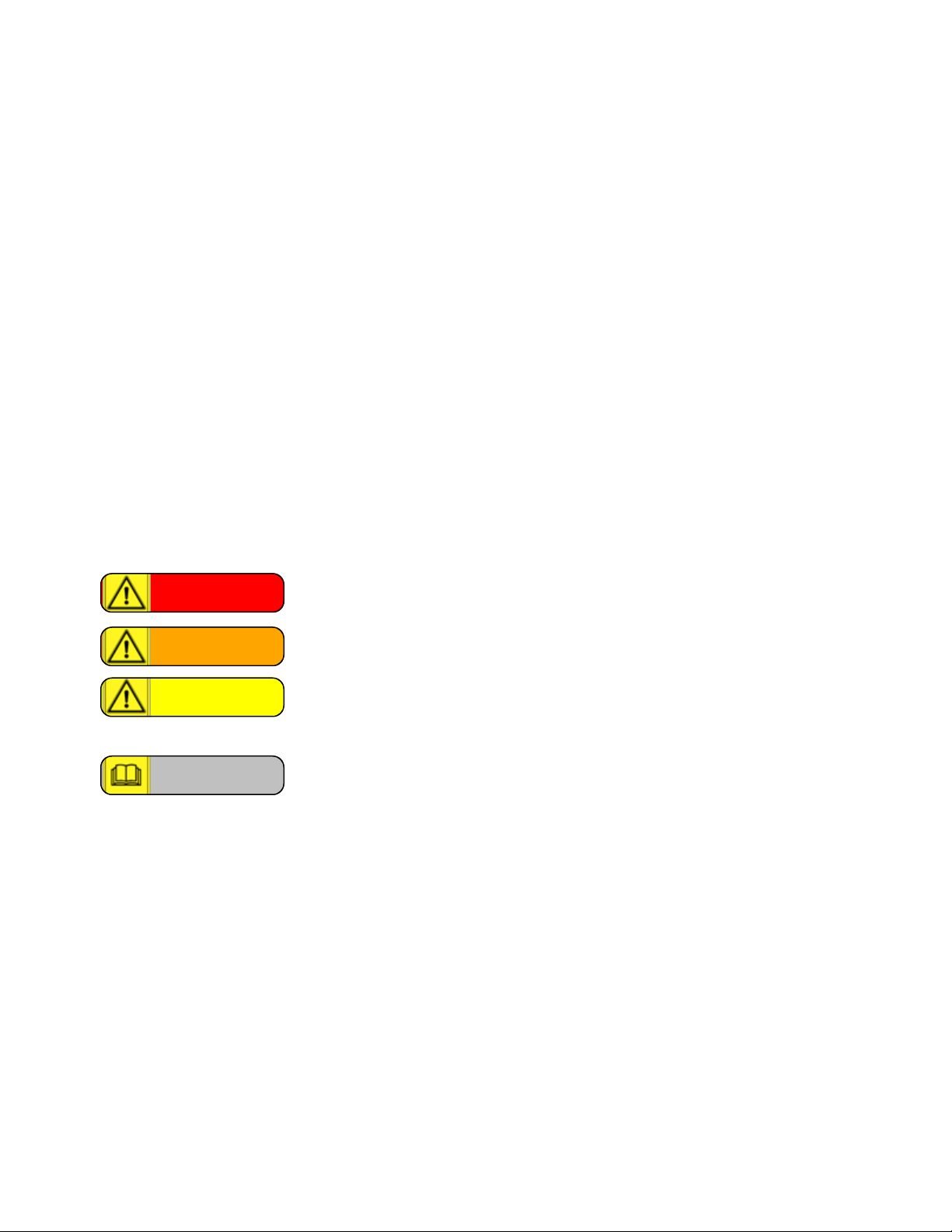
Table 1-1. Manual conventions
Danger:
Warning:
Caution:
Note:
Dangerous condition that, if not avoided, will result in serious or fatal
injuries.
Potentially dangerous condition that, if not avoided, could result in death or
serious injury, or damage to the tractor.
Condition that, if not avoided, can lead to injuries or damage to the tractor.
Alternative
Additional information
Risk of electric shock
Rick of chemical burns due to corrosive material
Risk of slipping
Risk of injury due to hot surface
Risk of explosion while charging battery
Risk of injuries from fluids under pressure
Risk of fire, flammable materials
Wear eye protection
Wear gloves
2
Page 12

1. Overview
Owner’s kit
The C992 tractor is delivered to a customer with the owner's kit which contents may vary depending on
the model option. In general, the owner's kit contains the following:
l operating manual
l maintenance schedule
l service book
l folder for tractor papers
l two ignition keys
l two door keys
l two fuel cap keys
l leather key pouch
l top link with plug
l two reducing sleeves for category 1 attachments
l hydraulic oil bio-pass
l bio-oil sticker for hydraulic tank
Brif overview of C992 tractor
The complete set of the specifications of the C992 tractor is outlined in Tractor Technical Data chapter.
The following table presents the most frequently referred specifications of the C992.
Table 1-1. C992 specifications
Specification Metric Imperial
Max. ground speed 40 km/h 25 mph
Permissible gross weight 4500 kg 9920 lb.
Curb weight 2563 kg 5651 lb.
Temperature range -30 to 50°C -22 to 122°F
Fuel tank capacity 82 L 21.7 gal.
Hydraulic tank capacity 45 L 11.0 gal.
Width 1.34 m 4.4 ft.
Length 3.73 m 12.2 ft.
Height 2.18 m 7.2 ft.
Max. torque 280 Nm 207 ft-lb
Max. inclination degree 40° (what conditions: tires, weight?)
Weight distribution and wind stability ROPS certificate (category?)
Engine: Deutz TD20011L04W l 4 cylinders
l turbo diesel
3
Page 13

1. Overview
Specification Metric Imperial
l 92 hp
Engine oil 5w40
Diesel fuel low sulfur
Applications of C992 tractor
The C992 Holder tractor is a 4-season tractor and designed to be used for the following:
l agriculture and forestry applications
l mowing and ground care
l snow removal
l street cleaning services
l trailer towing
If you use the C992 Holder tractor for the applications that the tractor is not intended for, and ignore or
do not follow the instructions and guidelines outlined in this manual, you can create a hazardous
situation that may lead to serious or fatal injuries, damage to the tractor, and voided warranty. Any
danger arising from impermissible use is a matter for which the user, not Holder Tractor Inc., bears
responsibility. Holder Tractor Inc. is not liable for any damage resulting from impermissible use. Using
Holder tractors for the purposes other than described in this manual is prohibited.
Registration and warranty
Every Holder tractor purchased from a Holder partner must be registered with Holder Tractors Inc. in
order to obtain warranty service.
To obtain your warranty and ensure its fulfillment, comply with the following:
l Register your tractor with a Holder partner within 30 days of purchase.
l Carry out the mandatory routine inspection as described in this manual.
l Operate your C992 as described in this manual.
l Follow the procedures outlined in this manual.
l Follow Holder's maintenance plan.
l Record all maintenance work in Holder's maintenance plan. Any maintenance work with your
C992 must be confirmed by an authorized by Holder service provider with the provider's stamp
and signature. To find a Holder service provider in your area, see the table below (?).
For the details of the warranty agreement, refer to the warranty certificate of your C992 tractor.
4
Page 14

Chapter 2. Safety and Accident Prevention
This chapter lists mandatory safety guidelines that the operator must follow at all times in order to
avoid any dangers, damage to the tractor and equipment, and voided warranty.
This chapter describes the following:
General safety guidelines 6
Safety guidelines with respect to particular situations 7
Risk of accident while driving 7
Risk of tractor tipping over 7
Risk of being entangled with moving parts 8
Risk of fire or explosion 8
Risk of electric shock 8
Risk of chemical burns from battery acid 9
Risk of injuries from pressurized fluids 9
Risk of explosion while charging battery 10
Risk of tractor malfunction due to installation of additional equipment 10
Risk of injuries from fluids and lubricants 10
Risk of poisoning or intoxication 11
Risk of slipping 11
Disposal guidelines and environmental protection 12
Page 15

2. Safety and Accident Prevention
General safety guidelines
The C992 Holder tractor is a powerful and high tech vehicle, designed with enhanced safety features.
However, if the tractor is not operated or maintained properly, it can lead to a hazardous situation.
Due to improper handling of the tractor, the following dangers may arise:
l accidents while driving, steering, and braking
l falling or stumbling in the cab when the tractor is moving
l unexpected movements of the tractor and attachments
l escape of fuels, lubricants, and other liquids due to leaks, damaged/frayed lines or tanks
l risk of fire from diesel fuel and oils
l risk of electrical fire
l other hazards caused by human errors
The operator must also be aware of any dangers that may arise due to adverse weather conditions,
limited visibility, surface conditions, traffic, and other factors that impact driving.
Danger: Failure to comply with the following guidelines can result in serious or fatal injuries.
In general, to avoid any dangers, damage to the tractor, and voided warranty:
l Use the tractor and attachments only as intended and specified in their manuals.
l Follow the maintenance plans of the tractor and attachments provided by the manufactures and
comply with the safety guidelines outlined in this manual.
l Ensure that the tractor is operated only by the persons who are well aware of all the safety
guidelines outlined in this manual.
l Ensure that the tractor and attachments are maintained and repaired only by the persons trained
and authorized to perform these tasks.
l Persons under the influence of drugs or alcohol may not work on or with the tractor.
l Follow the rules and regulations applicable in your area when driving, operating, and maintaining
the tractor.
l Do not transport people on the dump platform or attachments of the tractor.
l Do not carry any passengers. The C992 Holder is a single-occupancy tractor.
l Do not store or transport any hazardous substances in the cab.
l Do not make any modifications to the tractor or attachments unless it is approved by Holder.
6
Page 16

2. Safety and Accident Prevention
Safety guidelines with respect to particular situations
This sections defines safety guidelines that the operator must follow in order to avoid or prevent certain
hazards.
Risk of accident while driving
Warning: Failure to comply with the following guidelines could result in serious or fatal
injuries and damage to the tractor.
To avoid accidents wile driving:
l Drive according to the rules and regulations applicable in your area.
l Adapt your driving speed to the weather and road/surface conditions.
l Slow down before curves.
l Do not operate the tractor if there is a possibility of slipping, crashing, or tipping over.
l Keep a safe distance in front of the tractor in case you are required to quickly apply the brakes.
l Do not exceed the gross permissible weight of the tractor.
l Ensure proper weight distribution of the tractor. See ?
Risk of tractor tipping over
Warning: Failure to comply with the following guidelines could result in serious or fatal
injuries, and damage to the tractor.
Despite the superb stability characteristics of the C992 Holder tractor, the operator may cause
the tractor to tip over.
To prevent the tractor from tipping over:
l Maintain safe operating speed according to road/surface conditions.
l Slow down when
o
turning
o
working on slopes
o
carrying heavy loads
o
driving near ditches, ravines, excavations, embankments
o
driving on rough, soft or slick ground, or when visibility is restricted
l Use counterweights (front or rear end) to help keep the tractor stable when necessary. Follow
Holder's instructions when applying counterweights. Refer to ?
l Do not overload the tractor.
l Avoid abrupt steering and excessive braking.
l Install attachments only according to the installation guide of an attachment.
l Avoid backing downhill.
l Drive around ditches, not across them.
l Do not drive diagonally across a slope. Drive straight down even the gentlest slope.
7
Page 17
2. Safety and Accident Prevention
l While driving on a slope, ensure that the center of gravity does not exceed the tipping limit.
Lower center of gravity reduces the risk of tipping over.
l Ensure proper tire pressure and track width depending on the load.
Risk of being entangled with moving parts
Danger: Failure to comply with the following guidelines could result in serious or fatal
injuries, and damage to the tractor.
To avoid being entangled with moving parts of the tractor (Danger area picture):
l When the tractor is operating, keep clear from the center articulated area.
l Install and remove PTO shafts only when the engine is off.
l Do not allow anyone near the attachment zone when the PTO is engaged.
l Mount PTO guard chains as specified in the corresponding documentation.
l When the PTO is not in use, cover the tractor PTO drive shaft with a protective cap.
l Avoid wearing loose clothing or dangling jewelry.
l Wear proper headgear for long hair or braids.
Risk of fire or explosion
Danger: Failure to comply with the following guidelines could result in serious or fatal
injuries, and damage to the tractor.
To avoid fire or explosion:
l Do not smoke or light an open fire while handling fluids and lubricants.
l Keep the tractor and attachments clean, free of dirt, salt, and traces of fluid or lubricant leaks.
l Keep flammable materials far away from the exhaust system. Exhaust emissions can be extremely
hot.
l Never use the tractor in hazardous environments or near flammable vapors.
l If working near fuel or gas sources, follow the rules and regulations applicable in your area.
Risk of electric shock
Warning: Failure to comply with the following guidelines could result in serious or fatal
injuries, and damage to the tractor.
To avoid an electric shock:
l Disconnect the battery with the battery disconnect switch, the red key, before any work on the
electrical system.
l Always maintain a safety distance between the tractor and overhead power lines according to the
following table.
8
Page 18
2. Safety and Accident Prevention
Table 2-1. Safety distance to overhead power lines
Voltage Safety distance (m) Safety distance (ft.)
> 1 kV 1.0 3.5
< 1 kV > 110 kV 3.0 10.0
< 110 kV > 220 kV 4.0 13.5
< 220 kV > 1380 kV 5.0 17.0
Unknown voltage above 5.0 above 17.0
Risk of chemical burns from battery acid
Warning: Failure to comply with the following guidelines could result in serious or fatal
injuries.
Battery acid is a highly corrosive substance that, if in contact with skin or flesh, may
immediately cause extremely severe chemical burns.
To avoid chemical burns from battery acid:
l Wear proper personal protective equipment (PPE) in compliance with the health and safety rules
and regulations applicable in your area.
l Safety gloves and protective eyewear (glasses or goggles) must be worn at all times while
handling the battery.
l If the battery is leaking, immediately neutralize the leaking battery acid with baking soda solution
(1 lb. soda per 1 gal. water).
l In case of direct contact with skin or eyes, immediately rinse the contacted area thoroughly with a
saline solution and seek immediate medical attention. Refer to First Aid Measures section in the
material safety data sheet (MSDS) of the battery located on top of the battery.
Risk of injuries from pressurized fluids
Warning: Failure to comply with the following guidelines could result in serious or fatal
injuries, and possible damage to the tractor and equipment.
Escaping fluids under pressure travel at bullet speed, and their needle-like streams can
penetrate skin and flesh, and enter the bloodstream.
To prevent and avoid any injuries from fluids under pressure:
l Wear proper PPE in compliance with the health and safety rules and regulations applicable in
your area.
l Safety gloves and protective eyewear (glasses or goggles) must be worn at all times while dealing
with pressurized fluids.
l Never loosen hydraulic, fuel, or brake lines or coolant hoses while tractor is running.
9
Page 19

2. Safety and Accident Prevention
l As highly recommended by Holder, allow only an authorized service technician to work on the
hydraulic or brake system of the tractor.
l Secure the tractor and attachments to prevent uncontrolled movements before floating pressure
from the hydraulic or brake system (not related to fluid injuries?).
l Float hydraulic pressure before working on the hydraulic or brake system.
l In case of contact with eyes or a reaction due to skin contact, refer to First Aid Measures section
in the MSDS of a respective product and seek immediate medical attention.
l In case of spilling fluids, absorb them with absorbent mats or binding agents, as outlined in the
MSDS of a respective product, and dispose of them in compliance with the rules and regulations
applicable in your area.
Risk of explosion while charging battery
Warning: Failure to comply with the following guidelines could result in serious or fatal
injuries or damage to the tractor.
While being charged, the battery emits a potentially explosive gas mixture.
To avoid a possible explosion while charging the battery:
l Do not smoke near a charging battery or light an open fire while charging the battery.
l Charge the battery only in a well-ventilated area.
l Do not leave the battery on charge unattended.
Risk of tractor malfunction due to installation of additional equipment
Warning: Failure to comply with the following guidelines could result in injuries, or damage
to the tractor and equipment.
The electromagnetic radiation of additional equipment may alter the operation of the tractor
electronics, which may lead to the tractor malfunction and create a hazardous situation.
To avoid any danger due to the installation of additional equipment:
l Installation of any additional equipment must be approved by Holder and performed by a certified
Holder technician.
l All installed equipment must conform to Holder's power consumption guidelines (see ? section)
and comply with all the laws and regulations applicable in your area.
Risk of injuries from fluids and lubricants
Warning: Failure to comply with the following guidelines could result in injuries.
To avoid any injuries from fluids and lubricants (gear oil, engine oil, diesel fuel, hydraulic oil, brake
fluid, coolant):
10
Page 20

2. Safety and Accident Prevention
l Follow the safety instructions of a respective product as detailed on its MSDS.
l Wear proper PPE in compliance with the health and safety rules and regulations applicable in
your area.
l Safety gloves and protective eyewear (glasses or goggles) must be worn at all times while
handling these substances.
l Do not exceed the recommended fill level where applicable.
l In case of contact with eyes or a reaction due to skin contact, refer to First Aid Measures section
in the MSDS of a respective product and seek immediate medical attention.
l In case of spilling fluids and lubricants, absorb them with absorbent mats or binding agents, as
described in the relevant MSDS, and dispose of them in compliance with the rules and regulations
applicable in your area.
Risk of poisoning or intoxication
Danger: Failure to comply with the following guidelines could result in serious or fatal
injuries.
To avoid any possibility of being poisoned or intoxicated:
l Do not allow engine to run in enclosed spaces without no proper ventilation or exhaust extraction
system.
Emissions of diesel exhaust contain harmful components. Some of them are odorless and
invisible, and can kill without warning.
l Do not eat or drink when handling fluids and lubricants. If ingested, refer to the MSDS of a
respective product and seek immediate medical attention.
l Wear proper PPE in compliance with the health and safety rules and regulations applicable in
your area if working with or around aerosols and tractor emissions. If inhaled, retreat to wellventilated area and consult the relevant MSDS for further actions.
Risk of slipping
Warning: Failure to comply with the following guidelines could result in serious or fatal
injuries.
To avoid slipping:
l Get in and out of the cab facing the tractor.
l Keep the cab, handles, and steps clean.
l Avoid spilling fluids and lubricants. In case of spills, immediately absorb a spilled product with
absorbent mats or binding agents, as specified in the MSDS of a respective product, and dispose
of the waste in compliance with the rules and regulations applicable in your area.
11
Page 21

2. Safety and Accident Prevention
Disposal guidelines and environmental protection
To dispose of waste produced while operating the tractor:
l In case of spills, immediately absorb a spilled product with the appropriate absorbent mats or
binding agents, as specified in the corresponding MSDS, and dispose of the waste in compliance
with the rules and regulations applicable in your area.
l Dispose machine parts, fluids, lubricants, used filters, and other consumables in compliance with
the rules and regulations applicable in your area.
l Report to Holder Tractor Inc. if disposing of the tractor.
l When disposing of the tractor, beware that Holder Tractors Inc. does not accept any tractor
components for disposal.
12
Page 22

Chapter 3. Routine Inspection before Every Shift
This chapter describes the sequence of mandatory verification procedures that the operator must carry
out before every shift to ensure that the tractor is in proper operational condition. The order of the
verification procedures ensures the operator's safety during this routine inspection.
This chapter consists of the following procedures:
Getting ready for routine inspection 14
1. Checking battery and battery disconnect switch 14
2. Checking tires 15
3. Checking cab and rear view mirrors 16
4. Checking lights 16
5. Checking windscreen washer system 18
6. Checking horn and reverse alarm 18
7. Checking pedals and steering 19
8. Checking level of hydraulic oil 19
9. Checking level of brake fluid 20
10. Checking front lift arm assembly 21
11. Checking trailer coupling (?) 21
12. Checking heating and air-conditioning systems 22
13. Checking driver's seat and seat belt 23
14. Checking steering column 23
15. Checking radiator and dirt screens 24
16. Checking engine oil 24
17. Checking level of coolant 25
18. Checking engine air intake system 26
19. Checking alternator and AC/fan V-belts 27
20. Greasing joints and shafts 28
21. Checking safety/warning signs 29
Page 23
3. Routine Inspection before Every Shift
Getting ready for routine inspection
Warning: Failure to comply with the following guidelines could result in a potentially
hazardous situation.
l The mandatory verification procedures must be carried out before every shift.
l All safety and protection devices must be fully functional. They must not be removed or rendered
inoperative.
l During the routine inspection, the tractor must be stationary, inoperative and securely parked.
l If you detect any fault or non-compliance during the inspection, troubleshoot it. If the problem
persists, contact the nearest Holder-accredited service center. Do not operate the tractor unless it is
deemed safe to do so. Deficiencies must be corrected prior to operation.
l During the routine inspection, wear proper personal protective equipment (PPE) in compliance
with the health and safety rules and regulations applicable in your area.
Danger: Do not run engine in enclosed spaces without proper ventilation or exhaust
extraction. Failure to comply will result in serious or fatal injuries.
Emissions of diesel exhaust contain harmful components. Some of them are odorless and
invisible, and can kill without warning.
Before the routine inspection:
1. Ensure that the tractor is positioned on level ground with no inclination.
2. Ensure that the tractor is stationary:
l Drive direction switch is in neutral.
l Drive program switch is set to 0.
l Parking brake is engaged.
3. For enhanced protection, secure the tractor with wedges if wedges are available.
4. Turn the ignition key on but keep the engine off.
1. Checking battery and battery disconnect switch
This routine procedure verifies that the battery is in proper condition, and the battery disconnect switch
functions properly.
To check the battery and battery disconnect switch:
1. Ensure that the red removable key is turned on in the battery disconnect switch.
14
Page 24
3. Routine Inspection before Every Shift
Note: The power supply from the battery can be cut off completely or switched on with the
removable red key.
2. Ensure that all battery terminals and cables are secured and not damaged.
3. Inspect the battery for any signs of leaks.
4. If you detect any faults or non-compliance, refer to Troubleshooting chapter. Otherwise,
continue the routine inspection and go to the next procedure.
Caution: Turn off the battery disconnect switch if the tractor is not going to be used for
longer than six hours. Having the battery on during an extended period, may deplete or
damage the battery.
2. Checking tires
This routine procedure verifies that the tractor tires are in good condition.
To check the tires:
Warning: Failure to comply with the following guidelines could result in serious or fatal
injuries, and damage to the tractor and tires.
1. Verify that all four tires are the same size and type, e.g. agricultural, slope, all season M&S,
winter, soft track (terra tire), etc.
2. Verity that the type and size of the tires are appropriate for the operation. Do not exceed the load
capacity of the tires. Refer to the tire manufacture's specifications.
3. Inspect the tread and sidewall of all four tires for any damage, punctures or uneven wear. Do not
use damaged or worn out tires.
4. Ensure that the wheel nuts are not loose and have no signs of leaks around the wheel hub. If the
wheel nuts are loose, refer to Maintenance chapter.
5. If black wheel fenders or steel inner wheel fenders are installed, check them for damage and
ensure that they are secured.
6. Using a tire pressure gauge, check tire pressure on all four tires. All four tires must have the
same tire pressure.
7. Ensure that tire pressure is appropriate for the size and type of the tires, and the total tractor load.
Refer to the tire manufacture’s specifications and Tires section for correct pressure values.
Caution: Excessively high tire pressure creates a risk of explosion.
8. Adjust tire pressure if needed.
15
Page 25

3. Routine Inspection before Every Shift
Note: Inappropriate tire pressure will reduce service life of tires, increase rolling resistance,
which leads to greater fuel consumption, and may reduce driving comfort.
9. If you detect any faults or non-compliance, refer to Troubleshooting chapter. Otherwise,
continue the routine inspection and go to the next routine procedure.
3. Checking cab and rear view mirrors
This routine procedure verifies that the cab, step, and doors are in good condition, and that the rear view
mirrors are positioned properly.
To check the cab and rear view mirrors:
1. Inspect the step and ensure that it is secured and not damaged.
2. Ensure that the cab and step are free of dirt, spills, mud, snow, and other substances that may
cause slipping.
3. Ensure that the doors close properly.
4. Ensure that the rear view mirrors allow you to clearly see the road to the rear of the tractor and the
working area on both, right and left, sides of the tractor. Adjust the mirrors if needed.
5. If you detect any faults or non-compliance, refer to Troubleshooting chapter. Otherwise, continue
the routine inspection and go to the next routine procedure.
4. Checking lights
This routine procedure verifies that all tractor lights function properly.
Before checking the lights:
1. Ensure that the ignition key is on, but the engine is off.
To check the lights:
Caution: Non-functioning lights may lead to a potentially hazardous situation.
Note: The light switch has three sequential settings: off, position 1, and position 2.
1. Check the rear and top indicator lights.
a. Set the light switch into position 1.
b. Ensure that the light indicator in the instrument panel lights up.
c. Ensure that the top indicator lights are turned on.
d. Ensure that the rear indicator lights are turned on.
16
Page 26

3. Routine Inspection before Every Shift
2. Check the front low-beam headlights.
a. Set the light switch into position 2. The light switch illuminates.
b. Ensure that the front low-beam headlights are turned on.
3. Check the front upper headlights.
a. Turn the upper headlight switch on.
b. Ensure that the front upper headlights are turned on.
4. Check the front high-beam lights.
a. Move the multifunction lever down. If you have two multifunctional levers, use the lever
on the right side of the steering column.
b. Ensure that the high-beam indicator in the instrument panel lights up.
c. Ensure that the front high-beam lights are turned on.
5. Check the front and rear left signal lights.
a. Return the multifunction lever to its default position, then move it inward.
b. Ensure that the signal indicator in the instrument panel is flashing.
c. Ensure that the front and rear left signal lights are flashing.
6. Check the front and rear right signal lights.
a. Return the multifunction lever into its default position, then move it outward.
b. Ensure that the signal indicator in the instrument panel is flashing.
c. Ensure that the front and rear right signal lights are flashing.
7. Check the brake lights.
a. Press the brake pedal.
b. Ensure that the brake lights are turned on.
8. Check the hazard lights.
a. Turn on the hazard switch.
b. Ensure that the signal, trailer 1, and trailer 2 indicators light up in the instrument panel
are flashing.
c. Ensure that the front and rear indicator lights are flashing.
Note: If a trailer is attached, all trailer lights will work exactly the same as tractor lights.
9. Check the beacon light.
a. Turn on the beacon light switch.
b. Ensure that the beacon light is turned on.
10. Check the work light.
a. Turn on the work light switch.
b. Ensure that the work light is turned on.
11. Check the interior dome lights.
a. Turn on both interior dome lights located on the top left and right sides of the cab.
b. Ensure that the interior dome lights are turned on.
17
Page 27

3. Routine Inspection before Every Shift
12. Set all switches to their default positions.
13. If you detect any non-functional lights, refer to Troubleshooting chapter. Otherwise, continue
this routine inspection and go to the next routine procedure.
5. Checking windscreen washer system
This routine procedure verifies that the windscreen washer system function properly, and the
windscreen washer fluid reservoir contains appropriate amount of washer fluid.
Before checking the windscreen washer system:
1. Ensure that the ignition key is on, but the engine is off.
To check the windscreen washer system:
Caution: Lack of washer fluid may reduce an operator's visibility and lead to a hazardous
situation while driving.
1. Inspect the amount of washer fluid in the windscreen washer fluid reservoir. The reservoir is
located inside the cab, on the left front side in the radio console.
2. If needed, add windscreen washer fluid into the reservoir. The volume of the reservoir is
approximately 1.3 L / 1.3 qt.
Caution: Use appropriate to your region washer fluid to avoid windscreen freezing or
fogging.
3. If the tractor has two multifunction levers, skip step 5 and go to step 6.
4. If the tractor has one multifunction lever, press and hold the ring button located on the tip of the
multifunction lever to spray the washer fluid onto the windscreen and activate the wiper.
5. Turn the rotary switch on the multifunction lever to test the wiper in slow, continuous, and
intermittent modes.
6. If the tractor has two multifunction levers, (?)
7. Refer to Troubleshooting chapter if any of the following is present:
l Windscreen washer pump does not mist.
l Wipers do not function.
l Windscreen is not clear.
l Horn does not function.
Otherwise, continue the routine inspection and go to the next routine procedure.
6. Checking horn and reverse alarm
This routine procedure verifies that the horn and reverse alarm function properly.
18
Page 28

3. Routine Inspection before Every Shift
Before checking the horn and reverse alarm:
1. Ensure that the ignition key is on, but the engine is off.
To check the horn and reverse alarm:
1. Press the horn button at the end of the multifunction lever. The alarm will sound.
2. Set the program switch to 1.
3. Set the drive direction switch to reverse. Ensure that alarm sounds.
4. If you detect any faults or non-compliance, refer to Troubleshooting chapter. Otherwise, continue
the routine inspection and go to the next routine procedure.
7. Checking pedals and steering
This routine procedure verifies that steering and the tractor pedals function properly.
Before checking the pedals and steering:
1. Ensure that the ignition key is on, but the engine is off.
To check the pedals and steering:
1. Move the steering wheel side to side 3-4 times and ensure that it is not excessively loose. The
steering must feel tight.
2. Press the brake pedal and feel its resistance.
3. Release the brake pedal and ensure that it comes back automatically to its default position.
Note: The brake is a 4-wheel wet-disc, which is hydraulically actuated by applying pressure
to the brake pedal.
4. Press the throttle pedal and feel its resistance.
5. Release the throttle pedal and ensure that it comes back automatically to its default position.
6. Push the inch pedal all the way down to the floor. Ensure that it moves freely without any
resistance.
7. Release the inch pedal and ensure that it comes back automatically to its default position.
8. If any of the pedals does not function properly, refer to Troubleshooting chapter. Otherwise,
continue the routine inspection and go to the next routine procedure.
8. Checking level of hydraulic oil
This routine procedure verifies that the tractor has the appropriate amount of hydraulic oil.
Before checking the level of hydraulic oil:
1. Ensure that the ignition key is on, but the engine is off.
19
Page 29

3. Routine Inspection before Every Shift
To check the level of hydraulic oil:
1. Bring all tractor hydraulics and attachments downward.
2. To ensure a more accurate level reading for hydraulic oil, float hydraulic pressure from all six
tractor hydraulic systems:
a. For all six hydraulic float buttons on the keypad, press and hold every hydraulic float
button one at a time until the float button illuminates. The light in the button indicates
that pressure has been released from the corresponding hydraulic system.
3. Check hydraulic oil level through the sight glass on the hydraulic reservoir located behind the
cab on the right side of the tractor.
4. If hydraulic oil is below the min mark, follow the steps below.
Warning: Use only the hydraulic oil specified by Holder. Refer to Fluids and lubricants
section. Any other fluid will damage the tractor.
5. Remove the hydraulic reservoir cap and place it beside the reservoir. Do not lose the cap.
Caution: Do not add too much oil. The upper limit of hydraulic oil must be visible through the
sight glass.
(Picture: correct/incorrect)
Note: If the level of hydraulic oil is below the min mark, then the hydraulic system might be
missing up to 4 L / 1 gal. of hydraulic oil.
6. Using a funnel, slowly add the appropriate amount of the hydraulic oil specified by Holder into
the hydraulic reservoir through the fill tube only. While adding hydraulic oil, monitor its level
through the sight glass. Continue adding hydraulic oil until its level is above the min mark. If
after adding 4 L / 1 gal. of hydraulic oil, its level is still below the min mark, refer to
Troubleshooting chapter.
7. Reinstall the hydraulic reservoir cap and remove any spilled oil.
8. Verify that the hydraulic oil level is above the min mark.
9. Continue the routine inspection and go to the next routine procedure.
9. Checking level of brake fluid
This routine procedure verifies that the tractor has appropriate amount of brake fluid.
20
Page 30
3. Routine Inspection before Every Shift
To check the level of brake fluid:
Caution: Improper handling of brake fluid may lead to respiratory irritation. In case of
contact with eyes or skin, clean the affected area with water. Refer to First Aid Measures
section in the material safety data sheet (MSDS) of the brake fluid. Seek immediate medical
attention if symptoms worsen.
1. Locate the brake fluid reservoir behind the steering column.
2. Verify that the level of brake fluid is between the min and max marks.
Warning: Use only DOT 4 brake fluid. Do not mix brake fluids. Failure to comply will
damage the brake system.
3. If the level of brake fluid is below the min mark, add DOT 4 brake fluid to the appropriate level.
4. Continue the routine inspection and go to the next routine procedure.
10. Checking front lift arm assembly
This routine procedure verifies that the tractor front lift assembly does not have any missing or loose
components.
To check the front lift arm assembly:
Danger: Any loose, damaged, or missed components in the front lift assembly can cause an
attachment to tip, roll off, or fall to the ground, creating a hazardous situation, which if not
avoided, will result in serious or fatal injuries, and damage to the tractor.
1. Inspect the left and right sides of the assembly for the following:
l All four pinch bolt (two per side) and two lift arm pins (one per side) are secured in their
positions.
l Both front lift hooks (one per side) are not loose and do not move side to side.
l Both lift hook wedges (one per side) are secured in their positions.
l Both roll pins (one per side) are present on the bent arms, and one end of each pin
protrudes 0.5 in. from the opening.
2. Move front lift arm assembly side to side to verify that the front stabilizer link, two upper and two
lower front lift cylinder bearings, and upper and lower oscillating cylinder bearings are not loose.
3. If you detect any excessive play in between either the front lift stabilizer, or front lift cylinder
bearings, or oscillating cylinder bearings and their pins, refer to Troubleshooting chapter.
Otherwise, continue the routine inspection and go to the next procedure.
11. Checking trailer coupling (?)
This routine procedure verifies that the tractor trailer coupling functions properly.
21
Page 31
3. Routine Inspection before Every Shift
Danger: Any loose, damaged, or missed components used for the trailer coupling can cause
the trailer to tip over or roll off creating a hazardous situation, which if not avoided, will result in
serious or fatal injuries.
To check the trailer coupling:
1.
2. If you detect any faults or non-compliance, refer to Troubleshooting chapter. Otherwise, continue
the routine inspection and go to the next routine procedure.
12. Checking heating and air-conditioning systems
This routine procedure verifies that the heating and air-conditioning (AC) systems function properly.
Before checking heating and air-conditioning systems:
1. Ensure that the ignition key is on, but the engine is off.
To check the heating and AC systems:
Caution: Never operate the heating and AC systems without filters. Missing or clogged
filters may damage the tractor.
Note: The blower fan switch has three sequential positions corresponding to the following:
position 1- off, position 2 - low speed, position 3 - high speed.
1. Set the blower fan switch into position 1 to ensure that the blower fan works properly at the low
speed.
2. Set the blower fan switch into position 3 to ensure that the blower fan works properly at the high
speed.
3. If the AC system is not installed, skip steps 4-6, go to step 7.
4. Press and hold down the ACcondenser fan switch. The dual fan will spin in the opposite
direction blowing dust and dirt from the AC condenser.
5. If the dual fan is coated with dirt, gently clean it with soapy water or cleaning solution suitable for
copper and aluminum. Do not use any abrasive material or substances.
6. Inspect the back of the air condenser to ensure that the area is clean and free of any objects.
7. Inspect the rear cab filter. If the rear cab filter is heavily clogged, replace the filter. Otherwise,
clean the rear cab filter with compressed air at a maximum pressure of 70 psi and reinstall it.
8. From inside the cab, open the right-side door.
Note: The right-side door opens only from inside.
22
Page 32

3. Routine Inspection before Every Shift
9. Approach the right side of the cab from outside and locate the filter mat housing pull out tray.
Carefully pull the tray out and inspect the heater core filter. If the heater core filter is heavily
clogged, replace it. Otherwise, clean the heater core filter with compressed air at a maximum
pressure of 70 psi and reinstall it.
Caution: Clogged filters reduce air flow, which results in low AC efficiency and may cause
damage to the tractor.
10. If you detect any faults or non-compliance, refer to Troubleshooting chapter. Otherwise, continue
the routine inspection and go to the next routine procedure.
13. Checking driver's seat and seat belt
This routine procedure verifies that the operator is safe and comfortable in the driver's seat, and can
safely reach all devices in the cab and operate the tractor.
To check the driver's seat:
1. While sitting in the driver's seat, make sure that your position allows you to reach all the controls
in the cab and operate the tractor.
2. If not, adjust your seat. For instructions on how to adjust the driver's seat, see Adjusting driver's
seat procedure.
Caution: Ensure that the driver's seat locks after every adjustment.
3. Ensure that the seat belt is in good working condition and adjusted for you.
4. If you detect any faults or non-compliance, refer to Troubleshooting chapter. Otherwise, continue
the routine inspection and go to the next routine procedure.
14. Checking steering column
This routine procedure verifies that the position of the steering column is appropriate for the operator.
To check the steering column:
1. While sitting in the driver's seat, make sure that you are comfortable with the height and
inclination of the steering column.
2. If the position of the steering column has to be adjusted, release the adjustment lever by tuning it
counter clockwise. Now you can adjust the steering column back and forth, and slightly up and
down.
3. Set the steering column into the position comfortable for you.
4. Lock the lever by turning it clockwise until it is tight.
23
Page 33

3. Routine Inspection before Every Shift
5. If you detect any faults or non-compliance, refer to Troubleshooting chapter. Otherwise, continue
the routine inspection and go to the next routine procedure.
15. Checking radiator and dirt screens
This routine procedure verifies that the radiator and radiator screen are in proper condition.
To check the radiator and dirt screens:
1. Push and turn the radiator screen lock.
2. Carefully pull the radiator screen out of its housing and inspect the screen and radiator front for
cleanliness.
3. If necessary, clean the screen and radiator.
4. Inspect the radiator for damage and leaks.
5. Verify that the bottom of the radiator does not have any loose, damaged, or missing connections.
6. Inspect the bottom of the radiator for cleanliness. The area must be free of dust, dirt, mud, salt,
and any other foreign objects. If needed, clean the bottom of the radiator.
Caution: Any foreign objects such as trash, leaves, or dirt trapped in the radiator cause
radiator overheating, which leads to engine damage.
7. Reinstall the radiator screen.
8. If you detect any faults or non-compliance, refer to Troubleshooting section. Otherwise,
continue the routine inspection and go to the next routine procedure.
16. Checking engine oil
This routine procedure verifies that the tractor has the appropriate amount of engine oil.
Before checking engine oil:
1. Turn on the engine.
Caution: Joystick is a sensitive electronic device. Do not use force while operating it.
2. Lift the dump platform.
a. Press and hold button 1 on the joystick.
b. Pull the joystick backwards to lift the dump platform.
3. Shut off the tractor and remove the ignition key from the ignition to prevent accidental starting of
the engine.
4. Attach the dump platform safety guard and secure it with the lock pin.
24
Page 34

3. Routine Inspection before Every Shift
To check engine oil:
Warning: Dump platform can unintentionally fall down if not properly secured. Failure to
comply could result in serious or fatal injuries.
1. Pull out the dipstick from the round opening in the left rear side of the orange fender panel.
2. Wipe off the dipstick and then put it back, pushing it completely into the dipstick tube.
3. Pull the dipstick back out and check the oil level. The oil level must be between the min and
max marks.
4. If the oil level is below the min mark, follow the steps below.
Caution: Adding too much oil may cause engine damage. Use SAE 5W-40 engine oil only.
See Fluids and lubricants section.
5. Remove the yellow engine oil cap.
Note: If the level of engine oil is below the min mark, the tractor might require up to 2 L / 2
qt. of engine oil.
6. Add a small amount of SAE 5W-40 engine oil and check the engine oil level again. If it is
below the min mark, add another small amount of engine oil and then again check the engine oil
level. If after adding 2 L / 2 qt. of engine oil, the engine oil level is still below the min mark,
refer to Troubleshooting chapter.
7. Reinstall the yellow engine oil cap.
8. Continue the routine inspection and go to the next routine procedure if no faults or noncompliance is detected.
17. Checking level of coolant
This routine procedure verifies that the tractor has the appropriate amount of coolant.
Before checking the level of coolant, ensure the following:
1. The dump platform is secured with the safety support and the lock pin is installed.
2. The ignition key is not in the ignition and the engine has not been running in the last five
minutes.
To check the level of coolant:
Warning: Dump platform can unintentionally fall down if not secured with additional
support. Failure to comply could result in serious or fatal injuries.
25
Page 35

3. Routine Inspection before Every Shift
Warning: Never check coolant when the engine is hot. You can suffer serious burns from
extremely hot pressurized coolant.
1. Carefully remove the black radiator cap and inspect the coolant level in the radiator. Coolant
must be visible in the radiator fill pipe located at the top of the radiator.
2. Locate the yellow coolant overflow reservoir cap in the left rear corner of the engine
compartment.
3. Verify that the level of coolant in the coolant overflow reservoir is between the min and max
marks.
Caution: Use coolant that complies with Holder requirements. See Fluids and lubricants
section.
4. If the level of coolant is below the min mark, add coolant into the coolant overflow reservoir to
bring the level half way between the min and max marks. Do not overfill.
5. Close the coolant overflow reservoir and put the radiator cap back. Ensure that both caps are
secured.
6. If you detect any faults or non-compliance, refer to Troubleshooting chapter. Otherwise,
continue the routine inspection and go to the next routine procedure.
18. Checking engine air intake system
This routine inspection verifies that the engine air intake system is in proper condition.
Before checking the engine air intake system, ensure the following:
1. The dump platform is secured with the safety support, and the lock pin is installed.
2. The ignition key is not in the ignition, and the engine has not been running in the last five
minutes.
To check the engine air intake system:
Warning: Dump platform can unintentionally fall down if not secured with additional
support. Failure to comply could result in serious or fatal injuries.
Caution: Engine and exhaust system become very hot when the engine is running.
Note: If the tractor has been used in a dusty environment or in the operations such as
sweeping or mowing, the engine air filter must be checked before every shift. Otherwise,
check the engine air filter at least every week.
26
Page 36
3. Routine Inspection before Every Shift
1. Unlatch the strap clamp on the air filter housing and loosen the hose clamp.
2. Lift the engine filter housing and unlatch the three filter housing cover clamps.
3. Pull off the housing cover and clean the engine air filter housing.
Caution: Do not wash engine air filter. It will damage the filter and may cause damage to the
tractor.
4. Inspect the engine air filter. If the engine air filter is heavily clogged, or you detect carbon
residues or oil deposits in the engine filter, replace the engine air filter. Otherwise, clean the
engine air filter with compressed air at a maximum pressure of 70 psi and reinstall it.
Caution: Do not operate the tractor without an engine air filter. Do not use damaged filters.
Failure to comply will cause engine damage. If you attempt to operate the tractor with a
clogged engine air filter, alarm will sound.
Warning: Tampering with alarm system will void your warranty and may be a cause of
injuries and damage to the tractor.
5. Close the engine air filter housing and secure its cover with the three filter housing clamps.
6. Reinstall the engine air filter housing, and secure it with the strap and hose clamps.
7. Verify that the engine air intake stack is sturdy and securely connected to the flex hose.
8. Ensure that the air intake hoses are not damaged and the clamps along the air intake path are not
loose.
9. Verify that the engine air filter housing does not move.
10. If you detect any faults or non-compliance, refer to Troubleshooting chapter. Otherwise, continue
the routine inspection and go to the next routine procedure.
19. Checking alternator and AC/fan V-belts
This routine procedure verifies that the alternator and AC/fan V-belts are in good condition.
Before checking the alternator and AC/fan V-belts, ensure the following:
1. The dump platform is secured with the safety support, and the lock pin is installed.
2. The ignition key is not in the ignition and the engine has not been running in the last five
minutes
To check the alternator and AC/fan V-belts:
Warning: Dump platform can unintentionally fall down if not secured properly. Failure to
comply could result in serious or fatal injuries.
Caution: Engine and exhaust system become very hot when the engine is running.
27
Page 37

3. Routine Inspection before Every Shift
1. Remove the left rear orange fender to ease the access to the alternator V-belt.
2. Under the battery in between the radiator and engine, locate the V-belt and inspect it for wear and
cracks.
3. Test the tension of the V-belt: push it down or try to flip it. A well-tensioned V-belt cannot be
flipped or pushed down more than 10-15 mm.
4. Remove the right rear orange fender to reach the ACor fan V-belt, depending on whether the air
conditioner is installed.
5. Inspect the AC V-belt for wear, cracks, and tension.
6. If the V-belts are loose, refer to Troubleshooting chapter. If the V-belts are damaged and require
replacement, contact the nearest Holder-accredited service facility.
7. Reinstall both rear orange fenders and ensure that they are secured.
8. If you detect any faults or non-compliance, refer to Troubleshooting chapter. Otherwise, continue
the routine inspection and go to the next routine procedure.
20. Greasing joints and shafts
This routine procedure provides instructions on how to grease joints and shafts to prevent their
premature wear.
Before greasing joints and shafts:
Danger: Failure to comply with the procedure can cause uncontrolled tractor movements
that will result in serious or fatal injuries, and damage to the tractor.
1. Ensure that the tractor is stationary.
l Drive direction switch is in neutral.
l Drive program switch is set to 0.
l Parking brake is engaged.
2. Ensure that the ignition key is not in the ignition.
3. Have a grease gun loaded with multipurpose grease as specified by Holder. For the details, refer
to Fluids and lubricants section.
To grease joints and shafts:
1. Turn the steering wheel in one direction to the maximum.
2. Move the upper drive shaft by hand until the lubrication nipple is easily accessible.
Caution: Do not apply too much grease. It may damage the seal, and will clog U-joints and
drive shafts.
3. Grease the upper drive shaft U-joints until the grease comes out. Ensure that the grease gets into
the lubrication nipple.
4. Move the center drive shaft until the lubrication nipple is easily accessible?
28
Page 38

3. Routine Inspection before Every Shift
5. Grease the center drive shaft U-joints until the grease comes out. Ensure that the grease gets into
the lubrication nipple.
6. Move the lower drive shaft until the lubrication nipple is easily accessible?
7. Grease the lower drive shaft U-joints. Ensure that the grease gets into the lubrication nipple.
8. Grease the splines of the drive shafts.
9. Turn the tractor all the way to the left and right several times at slow speed to allow the grease to
spread in and onto the articulated shafts.
10. Lightly grease all 28 lubrication nipples, as shown on the picture.
21. Checking safety/warning signs
This procedure provides instructions on how to verify whether the tractor has all required
safety/warning signs in place.
To check the safety/warning signs inside the cab, inspect the following:
1. Upper corners of the windscreen for the following signs:
l Do not engage/disengage PTO above 1500 rpm.
l Do not engage diff lock above 1200 rpm.
l Air filter horn will sound if air filter requires maintenance. Check filter and clean or replace.
l Idle unit down before shutting down. Failure to do so may cause damage to turbo.
2. Steering column for the following signs:
l Seat belt must be worn in the vehicle at all times.
l Read this manual before operating the tractor.
3. Radio console for the sign:
l Do not transport people if the passenger seat is not available. Danger of injuries.
4. Right side of the joystick console for the sign:
l Speed control in # 3 or 4 (?)
To check the safety/warning signs outside the cab, inspect the following:
1. Right and left of the rear side of the cab for the signs:
l Presence in the articulated area is forbidden. Danger of severe crushing and injuries.
l Keep clear of the tractor center while in operation.
2. Left and right front sides of the dump box, if the dump box is installed for the sign:
l Do not overfill. Fill to top of box only.
Caution: If any sign is missing or damaged, contact the nearest Holder-accredited facility
for a replacement to ensure your warranty fulfillment.
29
Page 39

Chapter 4. Tractor Description
Page 40

Chapter 5. Tractor Technical Data
.
Page 41

Chapter 6. Driving Procedures
This chapter contains procedures describing how to drive the C992 Holder tractor.
Warning: Failure to comply with the following guidelines could result in serious or fatal
injuries, and damage to the tractor.
Only the operators who are aware of the safety guidelines defined in Safety and Accident
Prevention chapter can operate the tractor.
Before you start your shift, you must complete the routine inspection of the tractor to ensure that
the tractor is in proper operational condition. To inspect the tractor, refer to Routine Inspection
before Every Shift chapter.
This chapter consists of the following:
Getting ready to drive 33
Starting engine 33
Inch pedal 34
Driving hydrostatic tractor 35
Fine speed adjustment dial 36
Engaging/disengaging parking brake 37
Engaging differential lock 39
Driving with trailer 40
Page 42

6. Driving Procedures
Getting ready to drive
Warning: Failure to comply with the following guidelines could result in serious or fatal
injuries, and damage to the tractor.
To prevent any accidents while driving the tractor:
l Drive according to the rules and regulations applicable in your area.
l Maintain safe driving speed to the weather and road/surface conditions.
l Do not operate the tractor if there is a possibility of slipping, crashing, or tipping over.
l Keep a safe distance in front of the tractor in case you are required to quickly apply brakes.
l Do not exceed the gross permissible weight of the tractor.
l Ensure proper weight distribution of the tractor. See ?
To prevent the tractor from tipping over while operating the C992:
l Slow down when
o
turning
o
working on slopes
o
carrying heavy loads
o
driving near ditches, ravines, excavations, embankments
o
driving on rough, soft or slick ground, or when visibility is restricted
l Use counterweights (front or rear end) to help keep the tractor stable when necessary. Follow
Holder's instructions when applying counterweights. See ?
l Avoid abrupt steering and excessive braking.
l Hitch only at Holder's recommended height.
l Avoid backing downhill.
l Drive around ditches, not across them.
l Drive straight down even the gentlest slope, not diagonally across.
l While driving on a slope, ensure that the center of gravity does not exceed the tipping limit.
Lower center of gravity reduces the risk of tractor tipping over.
l Ensure proper tire pressure and track width with respect to the total permissible weight.
The picture below describes the recommended type of driving on slopes (Picture).
Starting engine
This procedure provides instructions on how to start the engine.
Before starting the engine, ensure the following:
Danger: Risk of intoxication
33
Page 43
Do not run the engine in enclosed spaces without proper ventilation or exhaust extraction.
Failure to comply will result in serious or fatal injuries.
1. No one is near the tractor.
2. Drive direction switch is in neutral.
3. Drive program switch is set to 0.
4. Parking brake is engaged.
5. Hand throttle is released.
To start the engine:
Warning: Start the engine only from the driver's seat and with cab doors closed. Failure to
comply could result in serious or fatal injuries.
Inch pedal
6. Driving Procedures
Note: The inch pedal allows the operator to control the ground speed of the tractor within a
gear-specific speed range. The amount of pressure applied to the inch pedal is proportional to
the amount of force applied to the gear system. The more pressure your apply to the inch
pedal, the greater the reduction in speed will be. If you need to slow down while operating
the tractor, you can use the inch pedal. It is possible in all driving programs and directions. If
you press the inch pedal all the way down, the tractor will abruptly come to a complete stop.
Caution: Use the inch pedal as prescribed to maintain control over the tractor and avoid
accidents.
1. Press the inch pedal completely down to actuate the starting safety switch. If the inch pedal is not
in the right position (completely down), the starting safety switch will not turn on.
Note: The ignition switch has four sequential positions: position 1 - tractor off, position 2 -
ignition on, position 3 - engine preheating, position 4 - engine running.
2. Using the ignition key, set the ignition switch into position 2 to start the ignition.
3. Ensure that the battery, engine oil pressure, and parking brake indicators in the instrument panel
light up.
4. Using the ignition key, set the ignition switch into position 3. Hold the key in position 3 until the
glow plug indicator in the instrument panel turns off. If the outside temperature is below
0°C/32°F, preheat the engine for one minute longer.
5. Using the ignition key, set the ignition switch into position 4. The engine starts, and the operating
hours counter activates.
34
Page 44
6. Driving Procedures
6. If the engine does not start, pause for one minute and then repeat step 4 again. If after two
attempts the engine does not start, see Troubleshooting chapter.
7. Let the engine run for at least 20 seconds to allow engine oil to circulate.
8. Go to Driving hydrostatic tractor procedure to start driving.
Note: To shut off the engine, turn the ignition key counter-clockwise and set it to position 1.
Driving hydrostatic tractor
This procedure provides instructions on how to drive the hydrostatic C992 Holder tractor.
Before driving the hydrostatic tractor, ensure the following:
1. Slow-moving vehicle sign is on the tractor and clearly visible to traffic.
2. No one is present near the tractor or its attachments.
3. Drive direction switch is in neutral.
4. Drive program switch is set to 0.
5. Fine speed adjustment dial is set to 0.
6. Parking brake is engaged.
To drive the hydrostatic tractor:
Warning: Start the engine only from the driver's seat with cab doors closed. Failure to
comply could result in serious or fatal injuries.
Caution: Bring the tractor to a complete stop before changing a driving direction or
program. Failure to comply may damage the tractor.
Note: Use the engine tachometer to monitor engine speed and the ground/PTO speed digital
display to monitor ground or PTO speed. To switch from ground speed to PTO speed, use
the ground/PTO speed digital display switch.
Note: When the tractor is switched to reverse, the backup alarm will sound.
Note: Driving comfort and traction can be increased by reducing tire pressure within the
limits corresponding to the total permissible weigh. See ?
1. Start the engine. Follow Starting engine procedure.
2. Ensure that the tractor is set for the right gear range with respect to the work you are planning to
do. See the table below for the details.
35
Page 45
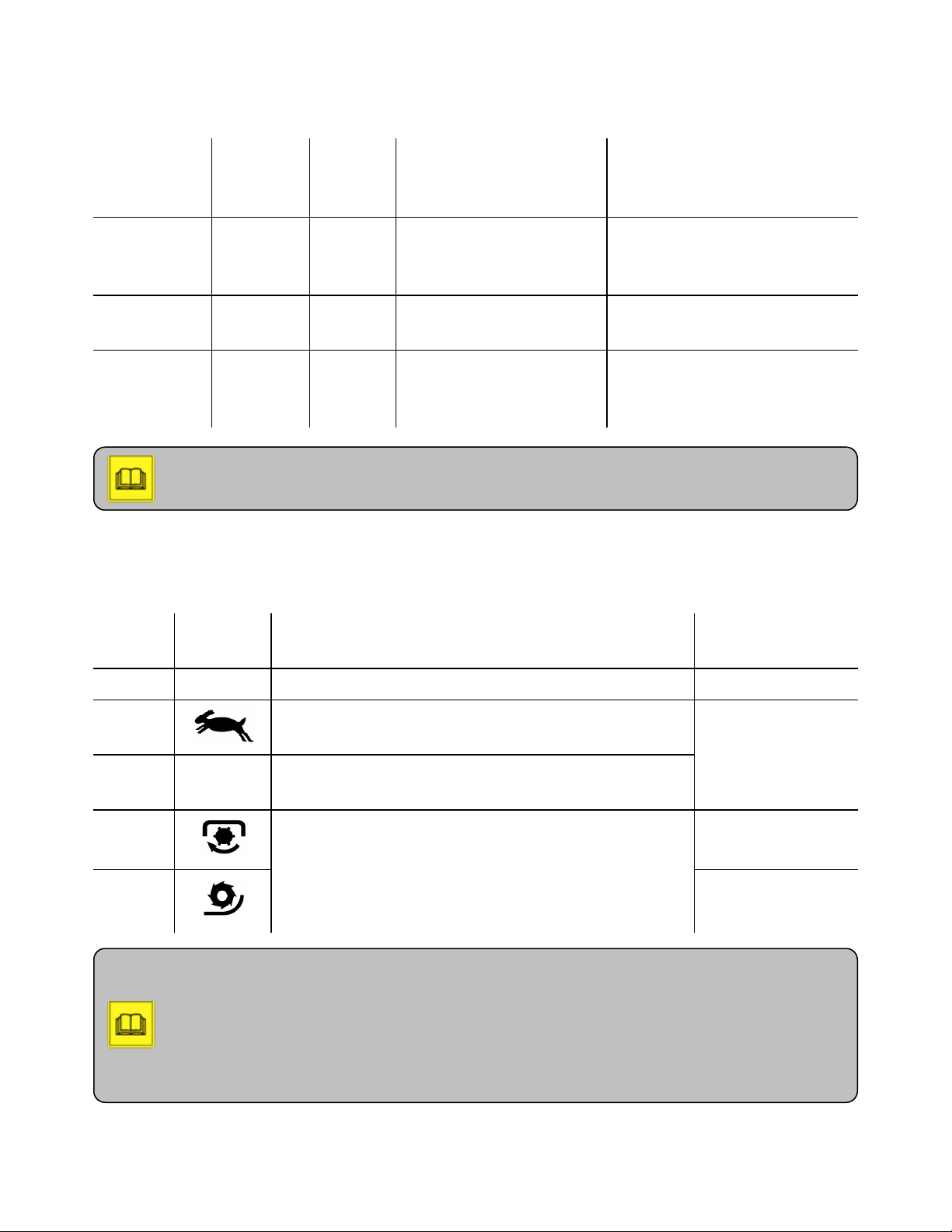
Table 6-1. Gear range
6. Driving Procedures
Symbol
S (fast, schnell
in German)
Position of
high/low
cable
low high gear 0-30 km/h (0-16.5 mph)
Gear
range
Ground speed range Recommended applications
driving to a location with
36 km/h (22 mph)
attachments not in use
maximum with dual drive
no symbol middle not
not applicable being towed
applicable
L (slow,
langsam in
German)
high low gear 0-12 km/h (0-7.5 mph) l operating attachments
l towing trailers
l driving on slopes
Note: Any extra weight added to the tractor such as loads, attachments, bigger tires, or a
trailer exerts an extra force to the tractor and affects its ground speed.
3. Set the drive program switch to the drive program appropriate for the work you are planning to
do. See the table below for the details.
Table 6-2. Drive programs
Drive
program
Symbol Designated function
Recommended
0 STOP setting ground speed to 0 stationary use
1
driving with the maximum ground speed in hydrostatic
and dual drive modes
road driving
2
3
driving with the maximum ground speed in hydrostatic
mode
l operating attachments with high power
requirements, e.g. PTO or hydraulically driven
best for mowing
attachments
4
l providing the operator with better control over the
ground speed.
best for snow
blowing
Fine speed adjustment dial
Note: In drive programs 3 and 4, the operator can control the ground speed independently
from engine and PTO speed with the fine speed adjustment dial. This dial provides the
operator with the most efficient way to operate an attachment while driving the tractor. With
this dial, the operator can seamlessly and gradually adjust the ground speed to the finest
application
36
Page 46
6. Driving Procedures
degree from zero in position 0 to the maximum in position 11. The speed preset on the fine
speed adjustment dial is controlled by the power requirements of the attachment. If while
operating the attachment, for example, plowing with the fine speed adjustment dial in position
5, the power requirements of the attachment increase (the tractor gets into a snowbank and
has to move a big pile of snow), the tractor slows down. When the power requirements for
the attachment decrease (the big pile of snow has been moved), the tractor accelerates back to
the ground speed corresponding to position 5.
4. Disengage the parking brake. Follow Engaging/disengaging parking brake procedure.
Note: If the dual drive system is installed on the tractor, see Driving with dual drive system
procedure. If the SDS system is installed on the tractor, see Driving with special drive system
(SDS) procedure.
5. If drive program 1 or 2 is selected:
a. Set the drive direction switch to either forward or reverse.
b. Actuate the throttle pedal to gain the appropriate ground speed.
6. If drive program 3 or 4 is selected:
a. If needed, engage the PTO. Follow Engaging PTO procedure.
b. Turn the hand throttle counter-clockwise to increase engine speed to at least 1500 rpm.
c. Set the drive direction switch to either forward or reverse.
d. Set the fine speed adjustment dial to the appropriate ground speed.
Engaging/disengaging parking brake
This section provides instruction how to engage/disengage the parking brake on the tractor. The current
version of C992 is equipped with automatic parking brake system, which is operated via a momentary
parking brake switch. The operator has to press the momentary parking switch in order to actuate it.
Previous versions of C992 are equipped with non-automatic parking brake system, which is operated
via a conventional on/off switch.
To engage the parking brake:
Caution: Always engage the parking brake before exiting the cab. Failure to comply may
create a hazardous situation that can lead to injuries.
1. Set the drive program switch to 0.
2. Set the drive direction switch to neutral.
3. Turn off the ignition key. If the tractor has automatic parking brake system, the light in the
momentary parking brake switch flashes and remains lit until the parking brake is fully engaged.
37
Page 47
6. Driving Procedures
4. If the tractor has non-automatic parking brake system, set the parking brake switch to on position.
Ensure that the light in the parking brake switch and the parking brake indicator in the instrument
panel flash and then remain lit indicating that the parking brake is fully engaged.
5. If you detect any irregularities in the parking brake system, shut down the tractor and see
Troubleshooting chapter.
To disengage the parking brake:
Note: The tractor must be running before disengaging the parking brake.
1. Turn on the ignition key and start the engine.
Caution: Traveling with the parking brake engaged will overheat brake components,
causing premature wear (of what?), and may lead to overheating seals, causing gear oil leaks.
If you attempt to drive with parking brake engaged, alarm will sound.
2. Set the parking brake switch to off position. If the parking brake switch is a momentary switch,
push it down and release.
3. Ensure that the parking brake indicator in the instrument panel and the light in the parking brake
switch are flashing.
4. Wait until the parking brake indicator in the instrument panel and the light in the parking brake
switch turn off, indicating that the parking brake is fully released. If you try to move the tractor
before the light and indicator are off, the alarm will sound.
38
Page 48

6. Driving Procedures
Engaging differential lock
The purpose of a differential lock is to lock both axles 1:1 so that all four wheels will spin at the same
speed in a low traction situation. Engaging the differential lock creates extreme shear forces in the gear
system that can easily damage the tractor.
Warning: Failure to comply with the following guidelines will result in damage to the tractor.
To avoid damage to the tractor and voided warranty while using the differential lock, the following
guidelines must be adhered to:
l Only use the differential lock in strait-line travel with engine speed 1200-1500 rpm maximum and
no wheel spin. If the wheels are spinning, damage can occur to the differential lock system. That
damage will not be considered a warranty repair.
l Only use the differential lock for extreme situations with low traction such as inclines to prevent
wheel spin.
l The differential lock is equipped with a momentary switch and therefore must be held in the
position in order for the system to be active.
l The differential lock must not be held on for a prolonged period of time.
l Do not attempt to use the differential lock when you have wheel spin.
l For cornering, you must switch off the differential lock.
To engage the differential lock:
Warning: Improper use of the differential lock or its abuse will cause massive damage to the
tractor and void your warranty.
1. Make sure that you are driving in a straight line, and the engine is running below 1500 rpm.
2. Ensure that no wheel spin is present.
3. Press and hold the differential lock momentary switch in the down position (Picture). The alarm
will sound, and the differential lock indicator in the instrument panel and in the LED light in the
differential switch will turn on, notifying the operator that the differential lock has been engaged.
4. If wheel spin occurs, release the differential lock switch immediately. You may engage the
differential lock again as soon as the wheels stop spinning.
Warning: Tampering with alarm system will void your warranty and may be a cause of
injuries and damage to the tractor.
Note: To disengages the differential lock, release the differential lock momentary switch.
The alarm will stop, and the differential lock indicator in the instrument panel will turn off.
39
Page 49

6. Driving Procedures
Note: If the differential lock cannot be switched off due to tension, carry out brief steering
movements to both sides until the differential lock releases. (Picture?)
Driving with trailer
This procedure describes how to drive the tractor with a trailer. The C992 tractor is suitable for towing
the following trailers:
Technically permissible trailer weights Permissible gross weight
Non-braked trailer weight 2500 kg / 5511 lb.
Trailer weight with independent braking 4000 kg / 8818 lb.
Trailer weight with overrun braking 4500 kg / 9920 lb.
Trailer weight with independent power-operated braking up to 12000 kg / 26455 lb.
The following trailer combinations are permissible:
l Tractor with single-axle trailer, braked or unbraked
l Tractor with single-axle trailer, braked or unbraked, followed by trailer with two-axle overrun
brake.
l Tractor with two-axle trailer, braked, followed by trailer with two-axle overrun brake.
l The total length of the combination may not exceed 18 m.
Warning
Risk of accident due to improper trailer coupling
l Secure trailer against roll-away.
l Do not allow people to be present between the tractor and the trailer.
l Completely close trailer coupling after coupling.
l Drive especially carefully when operating with trailers because the braking distance is increased.
l Do not drive faster than 25 km/h with a trailer not requiring licensing.
l Mark trailer with a sign indicating 25 km/h.
l The supporting load must be at least 25 kg (4% of the trailer load).
l The maximum supported load must not exceed 800 kg.
l The specified coupling load must be guaranteed during loading and unloading of the trailer.
l Undercutting of exceeding the supported load must be balanced out.
If you disregard these guidelines, there is a possibility of serious or fatal injuries and damage to the
tractor.
Caution
40
Page 50

6. Driving Procedures
Bring the tractor to a complete stop before switching between high and low gear to avoid damage to the
tractor.
To drive with a trailer:
1. Set the high/low cable to position L for low gear.
Note
The maximum traction is available in low gear.
2. Drive with a trailer as described in Driving hydrostatic tractor procedure.
41
Page 51

Chapter 7. Task-Oriented Procedures
This chapter contains procedures describing how to perform specific tasks.
Warning: Failure to comply with the following guidelines could result in serious or fatal
injuries, and damage to the tractor.
Only the operators who are aware of the safety guidelines defined in Safety and Accident
Prevention chapter can operate the tractor.
Before you start your shift, you must complete the routine inspection of the tractor to ensure that
the tractor is in proper operational condition. To inspect the tractor, see Routine Inspection before
Every Shift chapter.
This chapter contains the following task-oriented procedures:
Taking proper actions when alarm sounds 43
Parking tractor 44
Fueling 44
Adjusting driver's seat (mechanical seat?) 45
Wearing seat belt 47
Heating driver's seat 47
Heating rear-view mirror 48
Heating windscreen 48
Heating/ventilating/air-conditioning cab 48
Preheating engine oil 49
Opening roof hatch 49
Using roof hatch as emergency exit 50
Towing C992 50
Transporting/loading C992 51
Connecting a device to 12-V accessory socket 52
Page 52
7. Task-Oriented Procedures
Taking proper actions when alarm sounds
The alarm system consists of external and internal automatic horns with two distinctive audible
warnings, and a set of light indicators in the instrument panel. The alarm system warns the operator of
certain conditions that, if left without due attention, may result in damage to the tractor. The following
procedure provides instructions what the operator must do if the alarm turns on.
Warning: Tampering with alarm system will void your warranty and may be a cause of
injuries and damage to the tractor.
To take proper actions if the external alarm activates:
1. Stop the tractor and lift the dump platform.
2. Shut the tractor of and remove the ignition key.
3. Secure the dump platform with the safety support guard and let the tractor cool for five minutes.
4. Replace the engine air filter. See Checking engine air intake procedure. If a new engine air filter
is not available, clean the clogged engine air filter, reinstall it, and replace it as soon as possible.
To take proper actions if the alarm inside the cab activates:
Note:
The alarm activates automatically when the differential lock is engaged, notifying the
operator that
l Extreme shear forces have been applied to the tractor gear system.
l Differential lock cannot be used for a prolonged period of time.
If the differential lock is not engaged, there are three possible alarming scenarios:
l Coolant temperature is above 110°C (230°F) and the engine is overheating.
l Engine oil pressure is too low.
l You are driving with the parking brake engaged.
1. Check if the coolant temperature indicator is lit in the instrument panel, and the indicator in the
coolant temperature gauge is in the red zone.
2. If step 1 is true:
1. Stop the tractor but keep the engine running.
2. See Troubleshooting chapter.
Caution: Never shut off the engine if the coolant temperature gauge is in the red zone (p.
287).
43
Page 53
7. Task-Oriented Procedures
3. Check, if the engine oil pressure indicator in the instrument panel is lit while you are driving.
4. If step 3 is true:
1. Shut down the tractor.
2. See Troubleshooting chapter.
5. Check, if the parking brake indicator in the instrument panel is lit.
6. If step 5 is true:
1. Stop driving and turn the parking brake switch off.
2. Wait until the parking brake indicator in the instrument panel turns off, and the alarm stops.
Then, continue driving.
Caution: Traveling with the parking brake engaged will overheat engine oil, cause
premature wear, and possibly overheat the seals causing gear oil leaks. If you attempt to move
the tractor with the parking brake engaged, the alarm will sound.
Parking tractor
This procedure provides instructions on how to park the tractor.
To park the tractor:
1. Stop the tractor on level ground with no inclination.
Caution: The tractor may roll away if parked on a slope.
2. Bring the tractor to a complete stop.
a. Set the drive direction switch to neutral.
b. Set the drive program switch to 0.
c. Engage the parking brake. Follow Engaging/disengaging parking brake procedure.
3. Float the attachments completely (?).
4. Secure the tractor with wedges if wedges are available.
5. Turn off the engine and remove the ignition key from the ignition.
6. If you park the tractor for more than six hours, set the battery disconnect switch to off position.
Fueling
This procedure provides instructions on how to fuel the tractor.
To fuel the tractor:
Danger: Risk of fire
l Do not refuel near open flames, sparks, or hot engine parts.
l Do not smoke while refueling.
44
Page 54
7. Task-Oriented Procedures
l Keep fuel away from the battery.
l Do not exceed fuel tank capacity.
Failure to comply could result in serious or fatal injuries, and damage to the tractor.
Caution: Improper handling of diesel fuel may result in poisoning or slipping. See Safety
and Accident Prevention chapter.
1. Park the tractor.
2. Ensure that the engine is shut off.
3. Check the fuel gauge for the amount of fuel needed.
Note: The fuel tank capacity is 82 L / 21.5 gal.
4. Using a fuel cap key, unlock the fuel tank cap and remove the cap.
Caution: Use only low-sulfur diesel fuel. See Fluids and lubricants section. In case of
temperatures below 0°C/32°F, use diesel additives.
5. Through the fuel tank fill tube, add enough diesel fuel to replenish the fuel tank without
overflowing it.
6. Reinstall the cap on the fuel tank and lock it with the fuel cap key.
Adjusting driver's seat (mechanical seat?)
This section provides instruction how to adjust the driver's seat in various ways. The driver's seat on the
C992 tractor is air-sprung and can be adjusted for the following:
l backrest inclination
l seat horizontal suspension
l seat horizontal position
As an option, if the corresponding equipment is installed on the tractor, the driver's seat can also be
adjusted for the following:
l seat depth
l cushion inclination
l seat height
l armrest inclination
l lumbar support
l automatic weight adjustment
Caution:
45
Page 55

7. Task-Oriented Procedures
l Do not adjust the driver's seat while driving.
l Ensure that the seat locks after every adjustment.
Failure to comply may lead to loss of control over the tractor, which may result in serious or
fatal injuries.
To adjust the backrest inclination:
1. Sitting in the driver's seat, pull the backrest inclination lever upward and adjust the inclination
angle of the backrest using your back.
2. Release the backrest inclination lever and ensure that the backrest is secured in place.
Note: The backrest folds down if you pull up the backrest inclination lever when the seat is
unoccupied. To unfold it, simultaneously pull the backrest inclination lever upwards and lift
the backrest.
To switch on the horizontal suspension:
1. Unlock the horizontal suspension lever.
To adjust the horizontal position of the driver's seat:
1. Pull up the horizontal position adjustment bar and move the seat to the preferred horizontal
position.
2. Release the horizontal position adjustment bar and ensure that the seat locks into place.
To adjust the seat depth:
1. Pull up the right button on the seat adjustment panel at the front of the driver's seat.
To adjust the cushion inclination:
1. Pull up the left button on the seat adjustment panel at the front of the driver's seat.
To adjust the seat height:
Note: Adjust the seat height when the engine is running to avoid battery depletion.
1. Sitting in the driver’s seat, pull (where?) the seat height adjustment lever.
2. Release the lever when you find the right position and ensure that the seat locks into place.
To adjust the lumbar support:
1. Turn the lumbar support wheel until the most comfortable position is found.
46
Page 56

7. Task-Oriented Procedures
To adjust the inclination of the armrest:
1. Turn the armrest inclination adjustment wheel clockwise to raise the armrest, and turn it
counterclockwise to low the armrest.
Note: The air-sprung driver's seat adjusts automatically to an operator's weight when the
operator is in the driver's seat.
Wearing seat belt
This procedure provides instructions on how to wear the seat belt.
Warning: The seat belt must be fastened properly, as shown on the picture.
To fasten the seat belt:
1. Pull down the seat belt and ensure that the seat belt is not damaged.
2. If needed, adjust the seat belt.
3. Insert the seat belt latch into the buckle and push it down to fasten. When the seat belt latch locks
into the buckle, you will hear an audible click sound.
4. Ensure that the belt fits tightly and not twisted.
5. Ensure that the shoulder strap is positioned midway over your shoulder across your collar bone.
6. Ensure that the lap strap is positioned correctly, below the abdominal area.
To release the seat belt:
1. Press the release button in the locking buckle. The belt automatically draws back to the retractor.
Heating driver's seat
This procedure provides instructions on how to heat the driver's seat. This option is available if the
winter package is installed on the tractor.
To heat the driver's seat:
1. Ensure that the engine is running.
2. Turn on the seat heater switch.
47
Page 57

7. Task-Oriented Procedures
Heating rear-view mirror
This procedure provides instructions on how to heat the rear-view mirror . This option is available if the
winter package is installed on the tractor.
To heat the rear-view mirror:
1. Ensure that the engine is running.
2. Turn on the mirror heater switch. The mirror heater switch illuminates.
3. Once the rear-view mirror is clear, turn off the mirror heater switch.
Heating windscreen
This procedure provides instructions on how to heat the windscreen. This option is available if the
winter package is installed on the tractor.
To heat the windscreen:
1. Ensure that the engine is running.
2. Turn on the windscreen heater switch. The windscreen heater switch illuminates.
3. Once the windscreen is clear, turn off the windscreen heater switch.
Heating/ventilating/air-conditioning cab
This section provides instructions on how to control temperature and air flow in the cab.
Before heating/ventilating/air-conditioning the cab:
1. Ensure that the engine is running.
To heat the cab:
1. Turn the heating dial to the right.
2. Adjust the temperature in the cab with the heating dial to the left to decrease the temperature, and
turn it to the right to increase the temperature.
To ventilate the cab:
1. Turn on the blower fan switch.
Note: The blower fan switch has three sequential positions that correspond to the following:
position 0 - blower fan off, position 1- low speed, position 2 - high speed.
48
Page 58

7. Task-Oriented Procedures
2. Adjust the blower fan speed as needed. For low speed, press the blow fan switch down half way.
For high speed, press the switch down all the way.
Note: The ventilation system operates in two modes: supplying fresh air and air
recirculation. By default, the ventilation system supplies fresh air into the cab.
3. If needed, change fresh air supply mode to recirculation by turning the air supply knob counter-
clockwise.
4. Adjust the air nozzles for air direction and flow level:
l two nozzles on the front right side of the cab
l left and right dashboard nozzles
To air-condition the cab:
1. Ensure that the air-conditioner (AC) is installed on the tractor.
2. Turn the AC switch on. The AC switch illuminates indicating that the AC system is on.
3. Adjust the cooling temperature with the AC dial.
Note: If you have not used the air conditioner for more than 30 days, run it for at least two
minutes to ensure that the AC system is working.
Preheating engine oil
This procedure provides instructions on how to preheat engine oil before starting the engine in case of
low outside temperatures.-20°C/-4°F (?). Engine oil preheating is a special optional feature available
only if the corresponding equipment is installed on the tractor.
To preheat engine oil:
1. Locate the electric plug (term?) mounted on the left rear side of the tractor.
2. Using an electric extension cord (?), plug the female connector into the tractor-mounted plug and
the male (?) connector into ? 110 V AC voltage (?)
Caution: Connect an extension cord only to a ground fault circuit interrupter (GFCI) plug.
3. After the warm-up phase (?), unplug the extension cord from the tractor and cover the tractor-
mounted plug with the protective cap.
Opening roof hatch
This procedure provides instructions on how to open the roof.
49
Page 59
7. Task-Oriented Procedures
To open the roof hatch:
1. Grasp the handle on the roof hatch.
2. Press and hold the button on the side of the handle.
3. Push the handle up. The roof hatch opens gradually.
Using roof hatch as emergency exit
This procedure provides instructions on how to use the roof hatch in case of emergency.
To use the roof hatch as an emergency exit:
1. Open the roof hatch.
2. Pull out the inner plastic clip.
3. Pull the outer plastic clip. The roof hatch swings away.
Towing C992
This procedure provides instructions on how to tow the C992 tractor.
Warning: Failure to comply with the procedure could result in serious or fatal injuries, and
damage to the tractor and environment.
Caution:
l Do not tow the tractor for long distances. It may damage hydrostatic drive system.
l Do not tow the tractor with open roof hatch. It may damage the roof.
l While being towed, watch closely your C992 and surrounding area to avoid any damage
or injuries.
Before towing the C992 tractor:
1. The operator of the C992 tractor must ensure that the towing vehicle has sufficient traction and
braking force with respect to the gross weight and towed load of the C992 tractor, which is going
to be towed.
Note: The gross weight of the tractor is 2638 kg / 5816 lb. or 2790 kg / 6151 lb., depending
on tires.
To tow the C992 tractor:
1. Turn on the ignition.
2. Disengage the parking brake. Follow Engaging/disengaging parking brake procedure.
50
Page 60
7. Task-Oriented Procedures
3. Set the high/low cable to the middle position.
4. Set the drive direction switch to neutral.
5. Set the drive program switch to 0.
Note: Steering without hydraulic assistance, when the engine is off, requires extra force.
6. Ensure that the towing speed does not exceed 5 km/h (3 mph).
7. If towing is due to brake failure on the C992, attach and secure a towing bar to the front bumper
top link block of the C992 tractor. If the front bumper is not easily accessible, you can attach and
secure the towing bar to the rear block of the C992 tractor.
Transporting/loading C992
Warning: Only persons authorized to transport or load a damaged vehicle can perform this
procedure.
This procedure provides instructions on how to transport the C992 tractor onto a flatbed trailer or tractor
trailer when it is unsafe to tow the C992 tractor.
Danger: Risk of tractor falling down or tipping over
Transporting and loading C992 is a hazardous procedure and must be executed as outlined.
Failure to comply can result in serious or fatal injuries, and damage to the tractor and
environment.
To transport the C992 tractor:
Danger: Never stand or walk under or near the C992 tractor that is being loaded. There is a
risk of fatal injury.
1. Load the C992 onto either a flatbed trailer or transport trailer.
2. Park the C992 tractor on the transporting vehicle.
3. Secure the C992 tractor with wedges.
4. Ensure that the parking brake on the C992 tractor is engaged.
Caution: Use only straps, chains, and binders that comply with Holder requirements (?).
5. Secure the C992 tractor in the front at the top link slide and in the back at the towing device.
51
Page 61

7. Task-Oriented Procedures
Connecting a device to 12-V accessory socket
This procedure provides instructions on how to connect a portable electric device to the tractor
accessory socket.
To connect a device to the 12-V accessory socket:
1. Remove the cap from the 12-V accessory socket.
2. Ensure that the device to be connected is 15 A at most (?).
3. Plug the device into the socket.
Caution: Do not leave devices connected to the socket unattended when engine is off.
Battery may be discharged.
52
Page 62

Chapter 8. Attachments-Related Procedures
This chapter contains procedures describing how to handle and operate the tractor with attachments.
Warning: Failure to comply with the following guidelines could result in serious or fatal
injuries, and damage to the tractor.
Only the operators who are aware of the safety guidelines defined in Safety and Accident
Prevention chapter can operate the tractor.
Before you start your shift, you must complete the routine inspection of the tractor to ensure that
the tractor is in proper operational condition. To inspect the tractor, see Routine Inspection before
Every Shift chapter.
This chapter consists of the following:
Installing a PTO shaft 54
Engaging PTO 54
Disengaging PTO 56
Removing a PTO shaft 56
Page 63

8. Attachments-Related Procedures
Installing a PTO shaft
The PTO (power take-off) allows power from the engine to be transmitted to an attachment via a PTO
shaft. PTO shafts are unique for each attachment type and can be installed at the front or rear, if
equipped, of the tractor. This procedure provides general instructions on how to install a PTO shaft
regardless of an attachment.
Warning: Failure to comply with the procedure could result in serious injuries or damage to
equipment.
Before installing a PTO shaft, ensure the following:
1. Tractor is parked on level ground with no inclination.
2. Tractor is stationary:
a. Drive direction switch is in neutral.
b. Drive program switch is set to 0.
c. Parking brake is engaged.
3. Engine is off.
4. For enhanced protection, secure the tractor with wedges if wedges are available.
To install a PTO shaft:
1. Hold the PTO shaft in your hands with its collar end facing the PTO drive shaft of the tractor
(Picture).
2. Pull and hold back the collar of the PTO shaft, and slide the PTO shaft onto the tractor PTO drive
shaft.
3. Release the collar end and push the PTO shaft onto the tractor PTO drive shaft until it locks. You
will hear a click.
4. Push and pull the PTO shaft to make sure that it is fastened.
5. Hook the PTO guard chain to the tractor front or rear back depending on the attachment (Picture).
Engaging PTO
This procedure provides instructions on how to engage the PTO.
Warning: Failure to comply with the procedure could result in serious or fatal injuries, and
damage to equipment.
Before engaging the PTO:
1. Ensure that a PTO shaft and attachment have been properly installed.
54
Page 64
8. Attachments-Related Procedures
Warning: If an attachment is not installed properly, it may tip, roll off, or fall to the ground,
creating a hazardous situation, which if not avoided, could result in serious or fatal injuries.
To engage the PTO:
1. Bring the tractor to a complete stop:
a. Set the drive direction switch to neutral.
b. Set the drive program switch to 0.
c. Engage the parking brake. Follow Engaging/disengaging parking brake procedure.
2. Bring the engine to idle (?).
3. If the rear shaft is being engaged, turn the PTO speed selector lever on. If the front shaft is being
engaged, using the PTO speed selector rod (Picture), select the PTO shaft speed (540 rpm or
1000 rpm) as specified for the attachment installed.
Note: For 540 rpm, pull the rod completely out. For 1000 rpm, push the rod completely in.
4. Ensure that the engine is running below 950 rpm (how?).
Warning: Engaging PTO at engine speed higher than 950 rpm creates a tremendous shock
load on a PTO shaft. This improper use of PTO will cause massive damage to the tractor and
void your warranty.
Warning: Before turning the PTO switch on, make sure that there is nobody in the danger
area. Failure to comply could result in serious or fatal injuries.
5. Turn the PTO switch on. The PTO shaft will start rotating.
Warning: Exceeding the maximum engine rpm requirement for an attachment may cause
extreme damage to equipment and void your warranty.
Note: If the PTO is engaged but the engine is switched off, the PTO will switch off
automatically. To reactivate the PTO, restart the engine and turn the PTO switch on.
6. Turn the hand throttle counter-clockwise to increase engine speed to the appropriate rpm, as
specified for the attachment.
Note: While operating the PTO, you can view PTO speed by switching the ground/PTO
speed digital display from displaying ground speed to PTO speed. To do so, use the
ground/PTO speed digital display switch.
55
Page 65

8. Attachments-Related Procedures
Note: If PTO speed is 540, engine speed for most of the attachments is 2200 rpm. If PTO
speed is 1000 rpm, engine speed is 2390 rpm for most of the attachments.
Warning: If you need to leave the cab when PTO is engaged, disengage PTO (follow
Disengaging PTO procedrue). Then you may leave. Failure to comply could result in serous or
fatal injuries.
Disengaging PTO
This procedure provides instructions on how to disengage the PTO.
To disengage the PTO:
Warning: Disengaging PTO at engine speed above 950 rpm (when the engine is not idle?),
can cause severe damage to a PTO shaft and void your warranty.
Note: Monitor engine speed on the engine tachometer.
1. Push the top of the hand throttle to quickly release it and bring the engine rpm below 950 (set the
engine into the idle state?).
Note: You can also bring the engine rpm down by turning the hand throttle clockwise.
2. Bring the tractor to a complete stop:
a. Set the drive direction switch to neutral.
b. Set the drive program switch to 0.
c. Engage the parking brake (take it out? recomm. by Mitch).
3. Turn the PTO switch off.
4. Allow the PTO shaft to slow down to 0 rpm. Verify that PTO speed is 0 on the digital
ground/PTO speed display.
Warning: Attachments may lag after PTO is disengaged. Do not leave the cab until PTO
shafts stop rotating completely. Failure to comply could result in serious or fatal injuries.
Removing a PTO shaft
This procedure provides instructions on how to remove a PTO shaft.
Warning: Failure to comply with the procedure could result in serious injuries or damage to
equipment.
56
Page 66

8. Attachments-Related Procedures
Before removing a PTO shaft, ensure the following:
1. Tractor is parked on level ground with no inclination.
2. Tractor is stationary:
a. Drive direction switch is in neutral
b. Drive program switch is set to 0.
c. Parking brake is engaged.
3. For enhanced protection, secure the tractor with wedges if wedges are available.
4. Ensure that the PTO is disengaged, and the engine is off.
To remove a PTO shaft:
1. Remove the ignition key from the ignition.
Danger: Do not leave the cab until a PTO shaft stops rotating completely. Failure comply
could result in serious or fatal injuries.
2. Remove the PTO shaft guard chains.
3. Pull back the PTO shaft collar to release it from the locked position. Slide it off the PTO shaft
attached to the tractor PTO drive shaft, and remove the PTO shaft from the PTO drive shaft. The
PTO shaft stays with the attachment (Picture).
57
Page 67

9. Getting ready to work with attachments
Getting ready to work with attachments
The C992 Holder tractor is designed to be used with a variety of attachments such as
l winter service equipment such as blowers, plows, and others
l cargo beds
l cultivating implements
l mowers
l street maintenance equipment such as sweepers, high-pressure washers, and others
An attachment must be approved by Holder to be used with the tractor. Approved attachments are
marked CE (picture?). Note, that if a front or rear loader cannot be attached to a 3-point lifting device
(?), it cannot be used with the C992 tractor. Contact Holder Tractor Inc. before using special
implements.
Warning: Failure to comply with the following guidelines could result in serious or fatal
injuries, and damage to the tractor.
Before procuring or mounting the equipment (what kind?), ensure that it is suitable for an attachment (?)
(weight, suspension, rotational speed, power requirements, traffic safety, etc.).
In general, to avoid any injuries and damage to the tractor and equipment while operating the tractor
with attachments:
l Do not allow anyone near the tractor while coupling the tractor with an attachment.
l Couple an attachment as specified in the manufacture's manual.
l Follow the manufacture's instruction on how to use an attachment.
l Raise attachments and secure them against lowering while driving on roads.
l Drive with a loader only with the lifting frame lowered.; otherwise there is risk of an accident due
to the tractor tipping over.
l Completely lower all raised attachments when parking the tractor and during work pauses.
l The tractor must be securely parked before attaching equipment.
l Do not lift or transport people using attachments.
l Do not allow anyone to stand near or under lifted loads.
l When attaching implements to the front and rear 3-point linkages, never exceed
o
permissible gross weight
o
permissible axle loads
o
tire load capacity
l Load the front axle of the tractor with at least 20% and the rear axle with at least 25% of the
tractor's curb weight.
l Wear personal protective equipment during assembly work.
If you need to leave the cab while operating attachments:
58
Page 68

9. Getting ready to work with attachments
1. Set the travel direction lever to neutral when leaving the cab.
2. Set driving programme switch to 0.
3. Activate parking brake.
There are two mounting categories (categories of attachments):
l category 1 - bolt diameter 22 mm
l category 2 - bolt diameter 28 mm
The tractor is adjustable to both categories. The lift hook rails must also be adjusted and the catch hooks
must be equipped with or without reducing sleeves.
Attachments in compound with tipping system
Danger: In case of implements which are mounted and are operated on the hydraulic tilting
device , the hydraulic tilting device in lower condition must be protected against a unintentional
operation. If you disregard these guidelines, there is a possibility of severe or fatal injuries or
damage to the tractor.
For securing, adjust the valve to position B
Position A = Tipping
Position B= Rear lift
Safety guidelines when attaching counterweights
Danger: Failure to comply with the following guidelines can result in serious or fatal injuries,
and damage to the tractor.
l Do not exceed the following specifications of the tractor:
o
permissible gross weight
o
permissible axle loads
o
tire load capacity
l Load the tractor with at least 20% of the unladen weight of the tractor on the front axle and 25%
on the rear axle.
l Ensure that extra weights (counterweights?) are equal on both sides of an axle.
Calculating front/rear weights and counterweights
This procedure provides instructions on how to calculate front/rear weights and counterweights of the
tractor.
59
Page 69

9. Getting ready to work with attachments
Warning: Failure to comply with the following guidelines could result in serious or fatal
injuries, and damage to the tractor.
l When attaching implements to the front and rear three-point linkages, never exceed the
permissible gross weight, the permissible axle loads or the tire load capacity of the tractor.
l Always load the front axle of the tractor with at least 20% and the rear axle with at least 25% of
the tractor's curb weight.
1. Make sure that these requirements are satisfied before purchasing the implement.
2. Carry out the following calculations or weight the tractor-implement combination.
TLcurb weight of the tractor
TVfront axle load of the empty tractor
THrear axle load of the empty tractor
G
total weight of a rear attachment, rear weight
H
G
total weight of a front attachment, front weight
V
distance between the center of gravity of a front attachment, front weight and the center of the front
a
axle
b wheelbase of the tractor
c distance between the center of the rear axle and the center of the lower link ball
d distance between the lower link ball center and a rear attachment center of gravity, rear weight
1. Calculate the minimum front weight (G
G
= (GHx (c + d) - TVx b + 0.2 x TLx b) / (a + b)
V min
2. Calculate the minimum rear weight (G
G
= (GVx a - THx b + 0.25 x T x b ) / (b + c + d)
H min
3. Calculate the actual front axle load (T
T
= (GVx (a + b) + TVx b - GHx (c + d)) / b
V tat
H min
V tat
) according to the following formula:
V min
)according to the following formula:
) according to the following formula:
If the front attachment (GV) does not provide the necessary minimum front weight (GV min), the
weight of the front attachment must be increased to the weight of the minimum front weight.
4. Calculate the actual total weight (G
G
= GV+ TL+ G
tat
H
) according to the following formula:
tat
If the rear attachment (GH) does not provide the necessary minimum rear weight(GH min), the weight
of the rear attachment must be increased to the weight of the minimum rear weight.
60
Page 70

9. Getting ready to work with attachments
5. Calculate the actual rear axle load (T
T
H tat
= G
tat
- T
V tat
) according to the following formula:
H tat
6. Enter the values calculated in steps 1-5 into the Front/rear weight comparison table.
7. Enter twice the value (two tires) of the actual tire load capacity (see the tire manufacturer's
specification) into the table.
Table 9-1. [Front/rear weight comparison]
Double permissible tire load
capacity
Minimum weight front G
Minimum weight rear G
Calculated value Permissible value
V min
H min
Gross weight
Front axel load
Rear axel load
The minimum weight must be applied to the tractor as an attachment or counterweight.
The calculated values must be less than or equal to the permissible weight values.
Adjusting arrester hooks
This procedure provides instructions on how to adjust the arrester hooks.
To adjust the arrester hooks:
Danger of crushing
During installation (of what?), observe that there will not be any crushing of limbs. If you do not
observe these specifications, there is the danger of injury that lead to death, severe injury or damage to
the tractor.
1 Pinch bolt
2 Front lift arm
3 Pin
4 Bent arm
5 Quick-detach coupling
6 Reducing sleeves (Cat. 2 to Cat. 1)
61
Page 71

9. Getting ready to work with attachments
7 Lift hook
8 Wedge bolt
The spring washers under the nut (8) in the same direction mounting.
Lateral (is there any other?) adjustment of the arrester hook
1. Measure the bolt distances at your attachment.
2. Loosen the wedge bolts on both sides.
3. Move the lift hooks laterally until reaching the required dimension.
4. Tighten the wedge bolt.
5. You can incorporate category-2 devices directly with the arrester hook.
6. For category-1 devices, insert the adapter sleeves at the left and right.
Adjusting length of spigots
This procedure provides instructions on how to adjust the length of the spigots.
To adjust the length of the spigots:
1. Loosen the lock nuts and pinch bolt at the inside and at the bottom of the lift arm.
2. Loosen the screw on the pin and pull it out (Remove lynch pin and pull out the bolt).
3. You can adjust the bent arm to one of 3 positions (which ones?)
4. Re-insert the pin into the bore and secure with the screw (or option 2 Secure with the lynch pin).
5. Retighten the pinch bolts and lock nuts (1).
Table 9-1. Types of bores
Type Position Application
Bore 1 Front Category 1 and 2
Bore 2 Center Category 1
Bore 3 Rear Special equipment (?)
Adjusting top link slide / adjustable block
This procedure provides instructions on how to adjust the top link slide / adjustable block.
To adjust the top link slide / adjustable block:
Danger: Failure to comply with the following could result in serious or fatal
injuries, and damage to the tractor.
62
Page 72

9. Getting ready to work with attachments
l Do not turn the top links too far apart from one another.
l Ensure that threads are uniformly screwed into the spindle with at least five thread
courses.
l Check the thread length before attaching implements.
1. Lift the height adjustment lever.
2. Shift the guide block into one of the four possible positions. The height to be adjusted depends on
your attachment.
3. Release the height adjustment lever. The top link slide block will engage.
4. Pull the locking spring out of the top link pin and pull the pin out laterally.
5. Adjust the top link to the suitable length by turning the sleeve in or out. Secure the top link with
the locking lever.
6. Push the eye on the top link through the top link pin and again secure the top link pin with the
locking spring.
Coupling an attachment
This procedure provides instructions on how to couple an attachment.
To couple an attachment:
1. Drive the tractor to an attachment.
2. Steer the catch hooks under the support pins of the attachment.
3. Raise the front or rear lift, but only until the catch hooks reach the support pins of the attachment.
4. Adjust the top link to the suitable length and secure the top link.
5. Create the connection between attachment and tractor with the top link.
6. Carefully raise the front or rear lift until the quick-detach couplings close and lock.
Connecting/disconnecting hydraulic lines
This procedure provides instructions on how to connect/disconnect hydraulic lines between the tractor
and an attachment.
Before connecting hydraulic lines:
1. Ensure that you are well aware of all the information outlined in the manual for the attachment
that corresponds to connecting hydraulic lines.
2. Inform yourself about the functions and color markings.
3. Float pressure from hydraulic couplings.
4. Clean couplings on the tractor and on the hydraulic lines.
To connect hydraulic lines:
Danger: Risk of fire, hydraulic fluid is flammable
63
Page 73
9. Getting ready to work with attachments
Failure to comply with the following can result in serious or fatal injuries, and damage to the
tractor.
l Do not smoke or light an open fire while handling hydraulic fluid.
l Do not allow hydraulic fluid l to contact exhaust system.
Warning: Risk of slipping
Avoid spilling hydraulic fluid. Failure to comply could result in serious or fatal injuries, and
damage to the tractor.
Caution: Risk of injuries from fluids and lubricants
Failure to comply with the following could result in injuries and damage to the tractor:
l Wear personal protective equipment (safety gloves and glasses).
l Follow the manufacture's instructions of a product you are using.
1. Actuate the appropriate switches (ignition switched on) to float the hydraulic lines and
depressurize the hydraulic system.
2. Fold up the protective caps of the hydraulic couplings.
Warning: Risk of improper connection of hydraulic lines
Failure to comply with the following could result in serious or fatal injuries, and damage to the
tractor.
l Hydraulic plugs fit every hydraulic coupling and can therefore be mixed up. When
connecting, pay close attention to the function or movement of the attachment that is to
be carried out by operating the lever assigned to the hydraulic coupling.
l In case of unclear functions, undertake a test drive with respect to the connection
functions only in a secured area.
3. Connect the colored hydraulic lines of the attachment to the hydraulic couplings of the tractor of
the same color by pressing the plug into the coupling until it snaps into place.
4. The adjustable accessories hydraulic pump and flow divider II couplings are connected to one
another by turning the tractor-side ring clockwise.
To disconnect hydraulic lines:
1. Turn off the engine but keep the ignition on.
2. Actuate all switches of the hydraulic connections in use and of the lift several times. This reduces
the pressure in the hydraulic system and the hydraulics.
3. Push back the outer ring on the tractor and pull out the hydraulic coupling.
64
Page 74

9. Getting ready to work with attachments
Detaching an attachment
This procedure provides instructions on how to detach an attachment.
To detach an attachment:
Danger: Risk of accident from improper dismounting of attachments
In case of improper decoupling (detachment), the attachment can tip, roll off or fall to the ground.
Secure the attachment against tipping and roll-off before detaching. If you disregard these guidelines,
there is a possibility of severe or fatal injuries.
1. Switch off any PTO shaft that may have been switched on.
2. Drive attachment to parking place and lower with the rear or front lift.
3. Secure the tractor against roll-off.
4. Shut off engine, do not switch off ignition.
5. Actuate all switches of the hydraulic connections in use and of the lift several times. This reduces
the pressure in the hydraulic system and the hydraulics.
6. Push back the outer rings of the hydraulic couplings (1) and pull off the hoses (2). Protect
removed plug coupling from contamination.
7. Fold the protective caps of the hydraulic couplings (as at position 4) closed.
8. Remove the cardan shaft from the tractor's PTO shaft.
9. Cover the tractor's PTO shaft with the protective cap.
10. Remove the top link from the top link slide on the tractor.
11. Pull up the quick-detach couplings (3): The pins for the attachment will come free.
12. Lower the lift and drive carefully away.
Safety notes for operating hydraulic devices and attachments
Danger of poisoning
Risk of fire from hot exhaust system.
Risk of slipping
Warning against improper use of the tractor
Caution with leaking fluids and lubricants!
General warnings for operating the hydraulic floating position
Danger: Risk of accident from improper usage of the tractor
Never stand underneath attachments or tipping systems. When the floating position is switched on, a
lifted implement falls quickly or slowly to the ground, depending on the weight. If you disregard these
guidelines, there is a possibility of severe or fatal injuries.
65
Page 75

9. Getting ready to work with attachments
If floating position is switched on, the attachment can be moved by outside influences or move out of
the way of obstacles. The attachment is guided on the ground.
Transport protection
If the joystick function is blocked, you can prevent an inadvertent contact of the joystick or film
keyboard from moving the attachment. Use transport lock for road driving! The joystick and film
keyboard movements can be blocked with the master switch (5).
l Master switch off: joystick function and film keyboard blocked
l Master switch on: joystick functions and film keyboard enabled
Operating joystick
This procedure provides instructions on how to operate the joystick.
To operate the joystick:
Danger: Risk of accident from improper usage of the tractor
Carry out the test run at a secure location. Keep people away from the tractor during the test run.
Because of the variety of attachments and connection possibilities, check the functions for proper
operation by a test run before use. If you disregard these guidelines, there is a possibility of severe or
fatal injuries.
Note: The joystick can be moved down (forward) and up (backward), as well as to the right and the left.
Additional functions can be activated by pressing various keys. You can recognize the functions on the
sign plate.
Note: The functions of the attachments that are connected at the front lift or at the Front or rear hydraulic
couplings are controlled with the joystick. The couplings are color-marked, i.e., an identical color
corresponds to an identical assignment.
1 Button 1 for joystick level 1
2 Button 2 for joystick level 2
3 Button 3 for joystick level 3
4 Joystick (joystick level 0 with no button pressed)
5 Master switch for working hydraulics
Transport protection
The main switch (5) can switch the functions of the keypad and the joystick on and off or lock it: If the
main switch (5) is off, the joystick and the membrane keyboard functions are locked.
66
Page 76

9. Getting ready to work with attachments
Table 9-1. Proportional joystick operation, for sensitive operation
Joystick direction
Joystick level
Longitudinal (forward,
backward)
0 (without button) front lift Y0
forward: lower
back: lift
floating position on keypad
1 (button 1 pressed) tipping system / rear lift
(switchable via 3-way valve)Y1
forward: lower
back: lift
floating position on keypad
2 (button 2 pressed) front left plug-type coupling Y2
no floating position provided
3 (button 3 pressed) inclination adjustment of front lift
Y3 (contained in front lift)
forward: tilt to right
backward: tilt to left
Transverse (left, right)
right front plug-type coupling
X0
floating position X0 on keypad 2
right front plug-type coupling
X1
floating position X1 on keypad
rear left plug-type coupling X2
no floating position provided
side adjustment of front lift X3
alternatively: plug-type coupling
left: swivelling to left
right: swivelling to right
The operating conditions for the series joystick also apply for the multifunctional joystick (optional
equipment). The key numbers are identical, as for the S 1090.
1 Tipper, plug-in coupling blue
2 Plug-in coupling white, yellow
3 Quantity distributor 2, 12 Volt 1)
4 Quantity distributor 2, 12 Volt 1)
5 Device relief On, Off
6 Quick lift-out lifting
7 Float position Lift
8 Float position Incline
67
Page 77

9. Getting ready to work with attachments
9 Driving direction reverse
10 Front light-out, plug-in coupling green
Operating the multi-function joystick (picture)
Special functions
Button 3: Quantity distributor II or power outlet, e.g. for additional valve on device (present to
customer's request). Power outlet to 7-pin socket to pin 2.
Button 4: Side/inclination control or switched via button (optional equipment) to separate power output
e.g. for spreader additional function.
Operating a front-lifting attachment with joystick
This procedure provides instructions on how to operate a front-lifting attachment with the joystick.
To operate a front-lifting attachment with the joystick:
Switch on master switch (11) for working hydraulics. Lamp in the switch (11) and LED display singlyacting hydraulic function in button (17) is lit.
Lowering
Do not press any button, press joystick (10) forward and hold. The lift is proportionally lowered. Guide
joystick (10) back into the center position; lowering stops.
Lifting
Do not press any button, pull joystick (10) backward and hold. The lift is proportionally raised. Guide
joystick (10) back into the center position; lifting stops.
Floating position
Danger: Risk of accident from improper usage of the tractor
Never stand underneath attachments or tipping systems. When the floating position is switched on, a
lifted implement falls quickly or slowly to the ground, depending on the weight. If you disregard these
guidelines, there is a possibility of severe or fatal injuries.
Note: The float position can be activated at the multifunctional joystick either via button (4 or 7).
1. Push the button (3,) at the joystick or button (4, 7) at the multifunctional joystick or button (12) on
the foil keyboard. Float position is activated, the LED in the button (12) is lit, i.e. the attachment
lowers and can swerve due to outer effects during work.
2. Deactivate the float position by actively lifting or pushing the button (12) again. LED in button
(12) goes out.
68
Page 78

9. Getting ready to work with attachments
Danger: Risk of accident from improper usage of the tractor
The tractor can tip if the inclination adjustment is operated when the front hydraulics are lowered. If you
disregard these guidelines, there is a possibility of severe or fatal injuries.
Note: Button 3 = serial joystick C 992. Button 4 = multifunctional joystick.
Inclination adjustment
1. Press button (3, 4) and move joystick (10) forward or backward at the same time. The tail lift
inclination changes.
2. The tail lift will remain in the selected position after button (3) is released.
Side control
1. Press button (3, 4) and move joystick (5) to the right or left at the same time. The side adjustment
of the tail lift changes.
2. The tail lift will remain in the selected position after button (3) is released.
Floating position inclination adjustment
DANGER: Risk of accident from improper usage of the tractor
Never stand underneath attachments or tipping systems. When the floating position is switched on, a
lifted implement falls quickly or slowly to the ground, depending on the weight. If you disregard these
guidelines, there is a possibility of severe or fatal injuries.
1. Push button (8) at the multifunction joystick or button (20) on the foil keyboard. Float switch is
switched on, LED display in button (20) lights up, i.e. the lift can be moved by outer effects.
2. Deactivate the float position by pushing the button (20) or by holding button (4, 3) at the joystick
and moving the joystick forward or back. LED display in button (20) goes out.
Operating a front-lifting attachment with keypad
This procedure provides instructions on how to operate a front-lifting attachment with the keypad.
Switch on master switch (11) for working hydraulics.
Lowering
Note: Use the dial switch (13) to determine the speed for lowering and lifting the front lift. Turn to the
left = slower. Turn to the right = faster.
1. Press key (16). LED-display in button (16) and (14) remains lit until the front lift has been
lowered completely.
2. Set the lowering speed with dial switch (13).
Lifting
69
Page 79

9. Getting ready to work with attachments
1. Press key (15). LED-display in button (15) and (14) remains lit until the front lift has been lifted
completely.
2. Set the lifting speed with dial switch (13).
Note: Pushing the button (15, 16) again or moving the joystick (10) forward or back stops lowering or
lifting.
Floating position of the front lift
DANGER: Risk of accident from improper usage of the tractor
Never stand underneath attachments or tipping systems. When the floating position is switched on, a
lifted implement falls quickly or slowly to the ground, depending on the weight. If you disregard these
guidelines, there is a possibility of severe or fatal injuries.
1. To activate, press key (12). The LED indicator in button (12) lights up, i.e. the lift can be moved
by external effect.
2. Deactivate the float position by pushing the button (12, 15, 16) again or by actively lifting the
front lift via the joystick (10). LED in button (12) goes out.
Note: The float position can also be activated via the joystick, see page 227.
Danger: Risk of tractor tipping over
The tractor can tip if the inclination adjustment is operated when the front hydraulics are
lowered. Disregarding this information could result in serious or fatal injuries, and damage to
the tractor.
To adjust the inclination of a front-lifting attachment:
l Push and hold button (18) to tip the front lift to the right.
l Push and hold button (19) to tip the front lift to the right.
l Release the corresponding button to stop the movement.
Floating position of the inclination adjustment (?)
This procedure provides instructions on how to float position of the inclination adjustment
To float position of the inclination adjustment:
Danger: Do not allow anyone to stand under or near raised attachments or tipping systems
(?). Failure to comply will result in serious or fatal injuries.
When the floating position is switched on, a raised attachment falls quickly or slowly to the
ground, depending on the weight.
70
Page 80

9. Getting ready to work with attachments
l Push button (8) at the multifunction joystick or button (20) on the keypad. The LED indicator in
button (20) lights up, i.e. the lift can be moved by external effect.
l Deactivate the float position by pushing one of the buttons (18, 19, 20) or by holding button (3) at
the multifunction joystick and moving the joystick forward or back. LED display in button (20)
goes out.
Operating side adjustment with keypad
Operating the side adjustment via the foil keyboard
Side adjustment to the right.
1. Push and hold button (21). The front lift swivels to the right.
2. Release button (21). The movement stops.
Side adjustment to the left.
1. Push and hold button (22). The front lift swivels to the right.
2. Release button (22). The movement stops.
Floating position of the side adjustment
DANGER
Risk of accident from improper usage of the tractor
Never stand underneath attachments or tipping systems.
When the floating position is switched on, a lifted implement falls quickly or slowly to the ground,
depending on the weight.
If you disregard these guidelines, there is a possibility of severe or fatal injuries.
Procedure
1. To activate, press key (23). The LED display in the button (23) is lit, i.e. the attachment can swerve
due to outer effects during work.
2. Deactivate the float position by pushing one of the buttons (21, 22, 23) or by holding but-
ton (3) at the multifunction joystick and moving the joystick forward or back. LED display in button
(20) goes out.
71
Page 81
9. Getting ready to work with attachments
Switching front lift between single-acting and double-acting
This procedure provides instructions on how to switch the front lift between single-acting and doubleacting.
To switch the front lift between double-acting and single-acting:
Note: The front lift is always activated in single-acting mode when there is a restart or the
switch (11) for the working hydraulics is switched on. LED display in button (17) lights up.
1. Push the button (17) on the keypad. The illuminated button indicates that single-acting is
engaged. No light in the button indicates that double-acting is engaged.
To activate double-acting hydraulic function:
1. Push the button (17) on the keypad. The LED in the button (17) goes out.
To activate single-acting hydraulic function:
1. Push the button (17) on the keypad. The LED in the button (17) lights up.
To float the position with double-acting:
Danger: Never stand underneath attachments or tipping systems. When the floating
position is switched on, a lifted implement falls quickly or slowly to the ground, depending on
the weight. Failure to comply can result in serious or fatal injuries.
Note: When switching off the float position, the front lift returns to double-acting.
1. Press and hold the button (12) for approximately one second. The LED in the button (12) lights
up, signifying that the front lift can be moved by external effect.
To disengage floating:
1. Push the button (12) again or actively lift the front lift via the joystick (10). The LED in button
(12) goes out.
Volume flow limitation for joystick
Volume flow limitation for the joystick
3 The volume flow limitation permits setting and saving every single joystick function in the working
speed,
lifting, lowering, tilting, etc. The joystick movement remains proportional.
72
Page 82

9. Getting ready to work with attachments
10 The set volume current limit refers to
the max. joystick movement. You can save several joystick functions.
Procedure storage
1. Switch on master switch (11) for working hydraulics.
2. Push joystick (10) without any button or select a joystick function (1-4) with which the working
speed is to be changed.
3. Move joystick (10) to the corresponding level until the desired working seed is reached and hold it
there.
4. At the same time, push the button (24).
Working speed for this joystick function is saved.
Select other joystick functions and save them accordingly.
Procedure for deletion
1. Push joystick (10) without any button or select a joystick function (1-4) with which the working
speed is to be changed.
2. Move the joystick (10) in the corresponding level to the end and hold it there.
3. At the same time, push the button (24).
Working speed for this joystick function is saved.
Select other joystick functions and save them accordingly.
Switching functions
Switching functions
3 Use the button (27) to switch an additional function to the button
(3) at the joystick or
(4) at the multifunctional joystick.
10 These functions can be specified by your Holder service partner.
Possible functions on the button (3 joystick, 4 multifunction joystick)
S1090_074
1. Float switch tail lift (standard)
2. Floating position for green hydraulic coupling
73
Page 83

9. Getting ready to work with attachments
3. Float position front lift
4. Floating position for blue hydraulic coupling
5. Floating position inclination adjustment
6. Floating position of the side adjustment
7. Vine-tying machine
Possible functions on the button (3) at the multifunction joystick.
1. 12 V sockets front and rear
2. Volume divider 2
This function can be specified by your Holder service partner.
Procedure switching to float position (standard function)
Risk of accident from improper usage of the tractor
Never stand underneath attachments or tipping systems.
When the floating position is switched on, a lifted implement falls quickly or slowly to the ground,
depending on the weight.
If you disregard these guidelines, there is a possibility of severe or fatal injuries.
1. Lamp in the switch (27) and LED display singly-acting hydraulic function in button (12) is lit. Button
(3, 4) is activated as a button for the float position of the front lift.
2. Deactivate by pushing the button (27) again.
LED display in button (12) goes out.
Operating green hydraulic connections with joystick
Operating the green hydraulic connections* with the joystick
Procedure
1. Switch on master switch (11) for working hydraulics.
Operating the green hydraulic connections*
2. Do not press any button, press joystick (10) to the left or right and hold. The hydraulic function
green* is proportionally controlled.
3. Move joystick (10) back to middle position, hydraulic function stops.
S1090_071
74
Page 84

9. Getting ready to work with attachments
Floating position for green hydraulic couplings*
DANGER
Risk of accident from improper usage of the tractor
Never stand underneath attachments or tipping systems.
When the floating position is switched on, a lifted implement falls quickly or slowly to the ground,
depending on the weight.
If you disregard these guidelines,
there is a possibility of severe or fatal injuries.
Procedure
1. Push button (25) on the foil keyboard. Floating position is switched on. The LED display in the
button (25) is lit, i.e. the attachment can swerve due to outer effects.
2. Deactivate the float position, push button
(25) again. LED display in button (25) goes out.
* Optional equipment
Operating blue hydraulic connections with joystick
Operating the blue hydraulic connections* with the joystick
Procedure
1. Switch on master switch (11) for working hy-
Operating the blue hydraulic connections*
2. Press button (1) and press joystick (10) to the left or right and hold. The hydraulic function blue is
proportionally controlled.
3. Move joystick (10) back to middle position, hydraulic function stops.
S1090_072
Floating position for green hydraulic couplings*
DANGER
Risk of accident from improper usage of the tractor
Never stand underneath attachments or tipping systems.
75
Page 85

9. Getting ready to work with attachments
When the floating position is switched on, a lifted implement falls quickly or slowly to the ground,
depending on the weight.
If you disregard these guidelines,
there is a possibility of severe or fatal injuries.
Procedure
1. Push button (26) on the foil keyboard. Floating position is switched on. The LED display in the
button (26) is lit, i.e. the attachment can swerve due to outer effects.
2. Deactivate the float position, push button
(26) again. LED display in button (25) goes out.
* Optional equipment
Operating yellow hydraulic connections with joystick
1. Press button (2) and press joystick (10) to the left or right and hold. The hydraulic function yellow* is
proportionally controlled.
2. Move joystick (10) back to middle position, hydraulic function stops.
Operating the white hydraulic connections*
3. Press button (2) and press joystick (10) to the front or back and hold. The hydraulic function white*
is proportionally controlled.
4. Move joystick (10) back to middle position, hydraulic function stops.
ADVICE
The yellow and white hydraulic connections* have no floating position.
* Optional equipment
Operating electro-hydraulic implement relief
Operating the electro-hydraulic implement relief*
ADVICE
It only makes sense to use the im-
plement function* for an implement weight above 200 kg.
76
Page 86

9. Getting ready to work with attachments
Without electrohydraulic implement relief, the attached implement rests with its entire weight on the
ground in floating position. With electrohydraulic implement relief*, it is possible to transfer part of the
attached implement weight to the carrier tractor. This results in the following advantages:
• Improvement of traction
• Better steering and tracking of the tractor
• Less wear and tear, e.g. on the scraping blades of a snowplough
• Lower thrust forces together with reduced fuel consumption
• Improved stability on an incline
Procedure
ADVICE
After 3 seconds without any button being pushed at the display, the input values are saved and the
display will reset.
The display (1) will show the current pressure of the implement relief.
The value S.P.1 always has to be less than the pressure of the lifted attachment without implement relief.
1. Push button (24) on the foil keyboard. LED in button (24) lights up.
2. Push the button (3) "Mode". "S.P.1." appears in the display; the current value flashes after 2 seconds.
3. Use the button (4) to reduce the current value.
4. Use the button (2) to increase the current value.
The smaller the difference between S.P.1 and the lifted attachment device without implement relief, the
less weight is transferred to the carrier tractor.
* Optional equipment
Adjusting control sensitivity (hysteresis)
This procedure provides instructions on how to adjust control sensitivity. Higher value of HYS1
provide smoother implement relief. The smaller the value of HYS1, the more sensitively will the
implement relief work.
To adjust control sensitivity:
The pre-applied gas pressure in the membrane accumulator is 30 bar (psi?)
77
Page 87

9. Getting ready to work with attachments
A relief pressure below 30 bar (lightweight devices) leads to frequent control processes, since the
accumulator cannot act yet.
This control sensitivity sets the characteristics of the implement relief.
1. Push the mode button twice within three seconds. HYS1 appears in the display; the current value
(?) flashes after two seconds.
2. Use the button (name?) to reduce the current ? value.
3. Use the button (name?) to increase the current value.
Note: To switch off implement relief, push the button (24 name?) on the keypad and ensure
that the light in the button turns off.
Operating tipping system
Tipping framework can fall down
Working under the raised tipping framework is permitted only with additional support put into place.
When working with attachments, always ensure that they are secured to the tipping framework.
The tipping framework can unintentionally fall down.
If you disregard these guidelines,
Procedure
there is a possibility of severe or fatal injuries and damage to the tractor.
WARNING
Warning against improper use of the tractor
Prevent persons from being present in the danger zone of the rear end and the attachments when the
hydraulic equipment is in operation.
If you disregard these guidelines, there is a possibility of severe injuries.
Lowering
1. Push button (1) and push the joystick (10) forward at the same time. The tipping device* is lowered
proportionally. Guide joystick (10) back into the center position; lowering stops.
Operating floating position
DANGER
Risk of accident from improper usage of the tractor
Never stand underneath attachments or tipping systems.
78
Page 88

9. Getting ready to work with attachments
When the floating position is switched
1. Set the shift lever (A) at the rear in the "Tipping device*" position upwards.
2. Switch on master switch (11) for working hydraulics.
Lifting
1. Push button (1) and push the joystick (10) back at the same time. The tipping device* is lifted
proportionally. Guide joystick (10) back into the center position; lifting stops.
on, a lifted implement falls quickly or slowly to the ground, depending on the weight.
If you disregard these guidelines, there is a possibility of severe or fatal injuries.
ADVICE
The tipping system cannot be lifted if float position is activated.
Procedure
1. To activate, push button(28) on the foil keyboard; LED display in button (28) lights up,
i.e. the tipping device* will lower if lifted.
2. Deactivate the floating position by again pressing button (28); the red LED button indicator goes out.
* Optional equipment
Operating rear lift
Warning against improper use of the tractor
Prevent persons from being present in the danger zone of the rear end and the attachments when the
hydraulic equipment is in operation.
If you disregard these guidelines, there is a possibility of severe injuries.
Procedure
1. Set the shift lever (A) at the rear in the "Tipping device*" position upwards.
2. Switch on master switch (11) for working hydraulics.
Lowering
1. Push button (1) and push the joystick (10) forward at the same time. The tail lifting device* is
lowered proportionally. Guide joystick
(10) back into the center position; lowering stops.
Lifting
79
Page 89

9. Getting ready to work with attachments
1. Push button (1) and push the joystick (10) back at the same time. The tail lifting device* is lifted
proportionally. Guide joystick (10) back into the center position; lifting stops.
Operating floating position
DANGER
Risk of accident from improper usage of the tractor
Never stand underneath attachments or tipping systems.
When the floating position is switched on, a lifted implement falls quickly or slowly to the ground,
depending on the weight.
If you disregard these guidelines, there is a possibility of severe or fatal injuries.
Procedure
1. To activate, push button (28) on the foil keyboard; LED display in button (28) lights up,
i.e. the attachment can be moved due to outer influence.
2. Deactivate the floating position by again pressing button (28); the red LED button indicator goes out.
* Optional equipment
External control of rear lift and tipper
External control of the rear lift* and tipper
there is a possibility of severe or fatal injuries and damage to the tractor.
WARNING
Warning against improper use of the tractor
Prevent persons from being present in the danger zone of the rear end and the attachments when the
hydraulic equipment is in operation.
If you disregard these guidelines, there is a possibility of severe injuries.
WARNING
Warning against improper use of
Tipping framework can fall down
Working under the raised tipping framework is permitted only with additional support put into place.
When working with attachments, always ensure that they are secured to the tipping framework.
The tipping framework can unintentionally fall down.
80
Page 90

9. Getting ready to work with attachments
If you disregard these guidelines,
the tractor
Set the travel direction lever to neutral when leaving the cab. Set driving programme switch to 0.
Activate parking brake.
If you disregard these guidelines, there is a possibility of severe injuries or damage to the tractor.
You have the possibility of actuating the rear lift* or the tipper from outside the cabin.
Procedure
Lever (1a) at the top = Tipper Lever (1a) at the bottom = Rear lift*
1. Switch the switching lever at the left behind the left fender to the required function.
2. In order to lift the rear lift* or tipper, push the toggle switch (1) up. The rear lift* is lifted as long as
you keep pressing the toggle switch.
3. In order to lower the rear lift*, push the toggle switch (1) down. The rear lift* is lowered as long as
you keep pressing the toggle switch.
* optional equipment
External control of front lift
Procedure
1. Press key (1) up to raise the lift: The front lifting attachment is raised as long as the key is pressed.
2. Press key (1) downwards to lower the lift:
The front lifting attachment is lowered as long as the key is pressed.
WARNING
Warning against improper use of the tractor
Set the travel direction lever to neutral when leaving the cab. Set driving programme switch to 0.
Activate parking brake.
If you disregard these guidelines, there is a possibility of severe injuries or damage to the tractor.
Connection line between flow dividers
Connection line* between flow dividers I and II
is a possibility of severe or fatal injuries and damage to the attachment or the tractor.
81
Page 91

9. Getting ready to work with attachments
Figure_C 992_04
The delivery flow from flow dividers I and II can be combined with the connection line*. This then
yields a delivery flow of 0-50 l/min.
Procedure
1. Set the changeover lever (1) in the articulation area so it points downward.
The flow dividers I and II are now connected.
2. Set the rotary knob for flow divider II to the maximum position.
Set the desired delivery flow with the rotary knob of flow divider I.
3. Set changeover lever (1) so that it points to
Risk of accident from improper operation of attachments
Adjust the delivery flow to the power requirement of the attachment. An excessively large delivery flow
can lead to damage of the tractor and the attachment. This can cause hydraulic lines to burst and injure
bystanders. If you disregard these guidelines, there
the left.
Flow dividers I and II are now again disconnected.
* Optional equipment
Operating flow divider I
Risk of accident from improper operation of attachments
Adjust the delivery flow to the power requirement of the attachment. An excessively large delivery flow
can lead to damage of the tractor and the attachment. This can cause hydraulic lines to burst and injure
bystanders. If you disregard these guidelines, there is a possibility of severe or fatal injuries and damage
to the attachment or the tractor.
ADVICE
Operating the flow divider* properly
Activate flow divider (2) only at a low engine speed. Slowly increase the speed of the engine after
operating the switch.
If you disregard these guidelines, there is a possibility of damage to the tractor.
82
Page 92

9. Getting ready to work with attachments
The flow divider I* is used for driving a hydraulic motor in a device such as a salt spreader, hedge cutter
or the like with a variable power requirement. The working speed of the attachment can be adjusted
independently of the tractor's engine speed. The flow divider is fed by the hydraulic pump and operated
from the driver's seat.
Procedure
1. Connect the hydraulic hoses of the attachment to the red hydraulic couplings for drive
(1) and return (2) at the front of the tractor.
2. Switch on master switch (11) for working hydraulics.
3. Lamp in the switch (31) and LED display singly-acting hydraulic function in button (31) is lit.
4. Adjust the speed of the engine with the fine adjustment control to the desired rotational speed.
5. Use the dial switch (30) to set the working speed required for the attachment.
– Turn clockwise = speed is increased
– Turn anti-clockwise = speed is reduced
– The hydraulic motor in the attachment is supplied by an oil flow of 0-25 l/min.
6. Briefly press key (31) to switch off the flow divider. LED-indicator goes out
7. Switch off master switch (11) for the working hydraulics.
* Optional equipment
Operating flow divider II
Risk of accident from improper operation of attachments
Adjust the delivery flow to the power requirement of the attachment. An excessively large delivery flow
can lead to damage of the tractor and the attachment. This can cause hydraulic lines to burst and injure
bystanders. If you disregard these guidelines, there is a possibility of severe or fatal injuries and damage
to the attachment or the tractor.
Operating the flow divider* properly
Activate flow divider (2) only at a low engine speed. Slowly increase the speed of the engine after
operating the switch.
If you disregard these guidelines, there is a possibility of damage to the tractor.
83
Page 93

9. Getting ready to work with attachments
The flow divider II* is used for driving a hydraulic motor in a device such as a salt spreader, hedge
cutter or the like with a variable power requirement. The working speed of the attachment can be
adjusted independently of the tractor's engine speed. The flow divider is fed by the tandem pump and
operated from the driver's seat.
Procedure
1. Connect the hydraulic hoses of the attachment to the red hydraulic couplings for drive
(1) and return (2) at the rear of the tractor.
2. Switch on master switch (11) for working hydraulics.
3. Lamp in the switch (33) and LED display singly-acting hydraulic function in button (33) is lit.
4. Adjust the speed of the engine with the fine adjustment control to the desired rotational speed.
5. Use the rotary knob (3) to set the working speed required for the attachment.
– Turn clockwise = speed is increased
– Turn anti-clockwise = speed is reduced
6. The hydraulic motor in the attachment is supplied by an oil flow of 0-25 l/min.
7. Briefly press key (4) to switch off the flow divider. LED indicator goes out.
8. Switch off master switch (11) for the working hydraulics.
* Optional equipment
Operating power hydraulics
Operating the power hydraulics properly.
Switch on the key (4) only at a low engine speed. Slowly increase the speed of the engine after
operating the switch.
Make certain to switch the power hydraulics off if the attachment is not being used.
If you disregard these guidelines,
there is a possibility of damage to the tractor.
The power hydraulics are equipment for operating attachments with a fixed hydraulic power
requirement. They are operated electrically from the driver's seat.
Procedure
84
Page 94

9. Getting ready to work with attachments
1. Connect the hydraulic hoses of the attachment to screw-type couplings (1) and (2), and to leak oil
coupling (3).
2. Unlock the catch on the safety switch (4) and press the switch downwards. The indicator light in the
switch lights up.
3. Increase the speed of the engine slowly.
4. The attachment is supplied with an oil flow of approx. 80 l/min at the nominal engine speed.
5. Make certain to switch the power hydraulics off if the attachment is not being used.
6. To deactivate the power hydraulics, switch off the safety switch (4). Indicator lamp goes off.
Operating adjustable accessories hydraulic pump
Risk of accident from improper op-
eration of attachments
Adjust the delivery flow to the power requirement of the attachment. An excessively large delivery flow
can lead to damage of the tractor and the attachment. This can cause hydraulic lines to burst and injure
bystanders. If you disregard these guidelines, there is a possibility of severe or fatal injuries and damage
to the attachment or the tractor.
ADVICE
If a new or unknown attachment is operated with the adjustable accessories hydraulic pump*, the cable
set for implement coding ID no. 148873 must be used. The correct encoding must be determined in
coordination with the device manufacture and Max Holder GmbH.
The corresponding encoding of the device encoding adapter will determine
the max. oil volume for the attachment device (consumer). This is always required for operation.
Only 1 device encoding plug must plugged at the front or rear.
Switch the safety switch (6) on only at low motor speeds.
After increasing the motor speed, the oil flow must only be increased slowly. If these specifications are
not observed, damage to the tractor may result.
hydraulic power requirement, e.g. cylinder mowers. The working speed of the attachment device may
be set independently from the motor speed of the tractor.
The output of the device adjustment pump* can be adjusted from 0 to 120 l/min. They are operated
electrically from the driver's seat.
*Optional equipment
85
Page 95

9. Getting ready to work with attachments
Procedure
ADVICE
The adjustable accessories hydraulic pump* attempts to retain the specified oil quantity via the
implement plug and the potentiometer, even if the engine speed is reduced. The oil quantity is reduced
during a decrease of engine speed only if the maximum swash angle of the pump has been reached (see
diagram).
1. Connect the hydraulic hoses of the attachment at the front or back to the plug-type
couplings (1) for return and (2) for feeding and, if required, to the black leak oil coupling (4).
2. Connect the implement coding plug from the attachment to the socket (3) alongside the plug-type
couplings.
3. Set dial switch (5) to 0.
4. Unlock the catch on the safety switch (6) and press the switch downwards. The indicator light in the
switch lights up. The attachment is supplied with oil.
5. To set the oil flow, turn the dial switch (5) to the desired output of the attachment at 0-120 l/min.
The number 11 on the ring corresponds to the max. oil volume specified by the coding.
Switching off the adjustable accessories hydraulic pump*
1. To deactivate the pump, switch off the safety switch (6). Oil supply is switched off. Indicator lamp
goes out.
ADVICE
If you shut down the engine before switching off the adjustable accessories hydraulic pump*, the
adjustable accessories hydraulic pump* will not start, for safety reasons, after the engine is restarted.
Before restarting you must first either
2. Set dial switch (5) to 0 or
3. turn the safety switch on and off one time.
* Optional equipment
Flow dividers instructions
Important instructions for the operation of the flow dividers I and II and the implement pump*
ADVICE
Use the flow dividers I and II and the implement pump only as long as necessary.
86
Page 96

9. Getting ready to work with attachments
ADVICE
Switch off the flow dividers I and II and implement pump immediately after use so that the hydraulic oil
does not heat up unnecessarily.
ADVICE
The maximum pressure (set pressure) of the adjustable accessories hydraulic pump is 280 bar.
Attachments must be matched to this.
ADVICE
Avoid unnecessary oil heating by matching the available quantity of oil to the load (attachment).
ADVICE
Do not leave the flow divider or the implement pump switched on under any circumstances
• when the engine is running and no load is connected to the couplings
• when no load is operating
• when driving without oil consumption
* Optional equipment
ADVICE
The hydraulic system is damaged by excessive heating of the hydraulic oil.
87
Page 97

Chapter 10. Special Options (Additional Functions)
This chapter contains procedures corresponding to additional, enhanced functions of the tractor, which
are available as special options if requested by a customer.
This chapter contains the following procedures:
Engaging special drive system (SDS) 89
Engaging dual drive system 89
Page 98

10. Special Options (Additional Functions)
Engaging special drive system (SDS)
This procedure provides instructions on how to engage the special drive system (SDS). SDS is designed
for higher driving comfort and only available in low gear range. When SDS is engaged, the ground
speed is controlled with the throttle pedal and determined by the position of the fine speed adjustment
dial.
Before engaging SDS, ensure the following:
1. Tractor is at a complete stop.
2. High/low cable is set for low gear.
To engage SDS:
1. Set the drive program switch to 2.
2. Set the fine speed adjustment dial to the appropriate ground speed level.
3. If needed, adjust the required engine or PTO shaft speed with the hand throttle (?)
4. Use the throttle pedal to accelerate to the appropriate ground speed.
Engaging dual drive system
This procedure provides instructions on how to engage the dual drive system when the tractor has been
parked for an extended period (several hours) and the outside temperature is below 0°C/32°F. The
purpose of the dual drive system is to remove the hydrostatic system from operation and link the engine
directly to the final drive 1:1. The dual drive system is completely automatic. When the ground speed
exceeds 25 km/h (15.5 mph), the drive mode automatically switches from hydrostatic to mechanical
drive. When the ground speed falls below 25 km/h, the gear automatically switches back to hydrostatic
drive.
The dual drive system works only under the following conditions:
l Gear box is in high gear range.
l Drive program switch is set to 1.
Although the dual drive system is optional, it offers the following significant benefits:
l significant reduction of wear and tear of the hydrostatic system
l significant increase of the service life of hydraulic oil
l 40% increase in fuel efficiency
l reduced noise level
l higher maximum ground speed
l enhanced overall durability of the driving system
89
Page 99

10. Special Options (Additional Functions)
To engage the dual drive system:
Caution: Bring the tractor to a complete stop for switching between high and low gear to
avoid damage to the tractor.
1. Ensure that the high/low cable is set to high gear.
2. Set the drive program switch to 2.
3. Drive the tractor for approximately 10-12 minutes in program 2.
4. Bring the tractor to a complete stop.
5. Set the drive program switch to 1 and proceed driving. The dual drive system will engage
automatically when ground speed exceeds 25 km/h (15.5 mph).
6. If the engine stalls while accelerating, follow Engaging emergency start-up for dual drive system
procedure.
90
Page 100

Chapter 11. Maintenance Procedures
This chapter contains maintenance procedures.
Danger: Failure to comply with the following can result in serious or fatal injuries, and
damage to the tractor.
Maintenance and repair work should be performed as described in this manual and only by
licensed technicians or registered apprentices authorized to perform these tasks.
Welding, and all maintenance and repair work with the brake system, electronics, and electrical
system must be done only by the specialists trained to perform these tasks.
Only the persons who are aware of the safety guidelines defined in Safety and Accident
Prevention chapter can perform maintenance and repair work on the tractor.
Maintenance staff shall be trained by qualified employees of the manufacturer or its agents.
Persons with implanted devices, such as a heart pacemaker, or other health conditions must be
aware of the additional risks originating from the tractor.
This chapter consists of the following:
Getting ready for maintenance work 93
Following maintenance plan 93
Jacking up tractor 94
Tightening wheel nuts and threaded connections 95
Replacing a wheel 95
Adjusting track gauge 96
Coding digital speed display when switching to different tires/wheels 97
Shutting down tractor 97
Preserving engine 98
Removing hydraulic oil 98
Recommissioning tractor after shutdown 99
Bleeding fuel system 101
Tilting cab 101
Lowering cab 102
Replacing a light bulb 103
 Loading...