

Page 1

Operating Instructions
C-Trac 4.74
Order No.: 149 443
Date of Issue: 18.11.2005
Page 2

C 4.74
Foreword
Operating instructions
Congratulations on having bought a product from HOLDER.
You also ensure getting full value from your vehicle, save
yourself trouble and maintain your warranty. The operating
instructions provide you with the required information.
Development
Due to the continuous improvements made in the design
and equipment of our vehicles, deviations between these
operating instructions and your vehicle may be possible.
Despite taking all care possible in the creation of this manual,
we can not fully exclude mistakes. Please note therefore
that the information, illustrations and descriptions contained
herein can not be used for any legal claims.
These operating and maintenance instructions are supplied
with each vehicle. Keep them in a safe place where they are
available for the driver and owner at any time. If it should
get lost, the owner must get a replacement from the manufacturer.
The personnel concerned with the operation and maintenance of the vehicles must be made acquainted with the
operating and maintenance instructions. The owner must
ensure that every operator has received, read and understood this manual.
We thank you for reading and observing this manual. In
case you still have any questions, suggestions for improvements or discovered mistakes, please contact our customer
service.
General notes on service
Detach the warranty card, have it filled in by your dealer
and send the signed card to us.
Have the scheduled services carried out at the proper intervals and have it confirmed with the dealer’s stamp and signature in this manual. Please note that warranty can only
be claimed if the regular services have been carried out as
scheduled.
149 443 1
Page 3

Operating instructions
Foreword
In case of questions regarding your vehicle, please state
the following data:
Machine type .................................................... eg C 4.74
Engine serial number ................................... eg 00953643
Chassis serial number................................. eg 204000101
Date of sale or date of
complaint ................................................... eg 11.05.2005
Service hours ............................................... eg 500 hours
Date of issue and manual version
November 2005
We wish you safe driving and troublefree working with your
HOLDER C-Trac.
Gebrüder Holder GmbH
Max-Holder-Straße 1
72555 Metzingen
Phone 07123 966 - 0
Fax 07123 966 - 228
E-mail: info@holder-gmbh.com
C 4.74
Explanation of terminology:
DANGER
Indicates procedures which must be observed
exactly to prevent danger to the life and limbs
of persons.
CAUTION
Indicates procedures which must be observed
exactly to prevent personal injuries.
ATTENTION
Indicates procedures which must be observed
exactly to prevent damage to and/or destruction of objects and equipment.
NOTE
Indicates technical requirements needing
particular attention.
2 149 443
Page 4

C 4.74
Table of contents
Operating instructions
Foreword
Chapter PageChapter Page
Foreword ........................................................................ 1
Instructions for the vehicle ............................................ 5
Operating instructions .................................................... 7
Technical data ..............................................................15
Description ................................................................... 28
Taking into operation .................................................... 45
Operation ......................................................................59
Special operating instructions .......................................73
Operating the implements .............................................77
Other activities ........................................................... 111
Taking out of operation ............................................... 125
Trailers, towing ........................................................... 127
Transport, hoisting, towing ..........................................131
Indicators, adjustments .............................................. 135
Troubleshooting guide ................................................. 137
149 443 3
General remarks on maintenance ............................... 149
Maintenance schedule ................................................157
Maintenance during the first period of operation ......... 161
Maintenance as required ............................................. 163
Periodic maintenance ................................................. 167
Maintenance every 125 hours .....................................167
Maintenance every 500 hours .....................................175
Maintenance every 1000 hours ................................... 179
Maintenance every 1500 hours ................................... 183
Maintenance every 3000 hours ................................... 187
Annual maintenance ...................................................189
Laying up .................................................................... 191
Fuel and lubricant recommendations .......................... 193
Maintenance data .......................................................197
Alphabetical index ...................................................... 203
Page 5

Page 6

C 4.74
Instructions for the vehicle
Operating instructions
This vehicle has received the type approval acc. to 74/150/
EEC after a safety inspection. The vehicle conforms to the
EMC (Electromagnetic Compatibility) requirements of directive 89/336/EEC. The regulations for exhaust gas identification and the noise emissions are observed. The vehicle
must be registered and the licence plate must be attached
at the front and rear.
Intended Use
The vehicle can be used for towing trailers and for mounting
various implements. The maximum trailer load, which must
not be exceeded, is stated on the identification plate. The
transportation of persons is not allowed.
The vehicle is designed solely for the customary type of
operation in farming and forestry, the upkeep of municipal
facilities, including operation in winter.
The intended use also includes the performance of the specified maintenance. The vehicle and its implements may only
be used, serviced and repaired by persons familiar with this
equipment and have been warned of possible risks. The applicable safety regulations must be strictly observed, along
with all other recognized rules regarding industrial health,
safety at work and the highway traffic code.
Site of operation
The vehicle must be used in the open. Its operation on public roads is allowed. Observe the applicable regulations in
your country for driving your vehicle on public roads.
Unintended applications
Any use not intended as described as above is an unintended use. HOLDER will not be responsible for any hazard
which may result from unauthorized use. The manufacturer
will also not be responsible for any resulting damages; these
shall be solely borne by the user. The vehicle may not be
used for any other purposes than those described in this
manual. Do not carry persons on the load platform or on the
implements.
149 443 5
Page 7

Operating instructions
Instructions for the vehicle
Residual hazards and risks
C 4.74
Despite all care being taken and compliance with standards
and regulations, it is not possible to exclude all risks in the
handling of the vehicle.
The vehicle and all other system components conform to
currently applicable safety regulations. A residual risk can
not be excluded even with approved use of the vehicle and
with observation of all the safety notices given.
For this reason, persons standing in the area the vehicle
and implements must exercise particular caution in order to
be able to react directly in case of malfunction, an incident,
a failure, etc.
CAUTION
All persons standing in the area of the vehicle and implements must be advised of the
risks which can result from their operation.
Furthermore, read and observe the other
safety rules and regulations contained in
these operating instructions.
The risks can include:
- Unexpected movements of the implements and the
vehicle.
- Escape of fuel and lubricants due to leaks, broken
lines and containers, etc.
- Risk of accidents when driving, steering and braking
due to unfavourable ground conditions such as
slopes, icy roads, unevenness or poor visibility, etc.
- Falling, stumbling, etc. when moving on the vehicle,
particularly if it is wet.
- Danger of fires and explosion through the battery and
electric voltages.
- Danger of poisoning through diesel exhaust fumes.
- Danger of fire through diesel fuel and oils.
- Human misconduct through the non-observance of
safety rules.
Notes on disposal of vehicle
Your vehicle is made of different materials. Each material
should be disposed of/treated/recycled according to different regional/national regulations. We recommend contacting a salvage company.
6 149 443
Page 8

C 4.74
Operating instructions
Driver’s licence
For the driving of this vehicle you require a driver’s licence
depending on the maximum driving speed and the permissible total weight of the vehicle and combinations. See the
tables below.
Driver’s licence classes
Tractors for farming and forestry (also with implements)
Operating instructions
Maximum Speed
(dependent on type)
up to 32 km/h
over 32 km/h
149 443 7
Maximum Total Weight
no limitation B, L, T 1, 1a, 1b, 2, 3, 4, 5
up to 3.5 tons B
over 3.5 tons
to 7.5 tons
Driver's License Class
(Minimum Requirements)
T: 60 km/h,
under 18 years
only 40 km/h
C1
T: 60 km/h,
under 18 years
only 40 km/h
Former Driver's License
Class (Germany)
2, 3
2, 3
Page 9

Operating instructions
Operating instructions
Single-axle trailers or two-axle trailers with axle base of up to 1 metre maximum
C 4.74
Maximum Total Weight
up to 750 kg trailer weight B, C1, C, T
over 750 kg trailer weight BE, C1E, CE, T
Driver's License Class
(Minimum Requirements)
25
L: only with additional
sign and maximum tractor
speed of 25 km/h
(depending on type)
B, C1, C: only up to
3.5 tons adm. total weight of
the combination and adm.
total weight of trailers
≤ kerb weight of tractor;
otherwise:
C1E: only up to 12 tons adm.
total weight of combination
and adm. total weight of trailer
≤ kerb weight of tractor;
otherwise:
25
L:
25
Former Driver's License
Class
1, 1a, 1b, 2, 3, 4, 5
1, 1a, 1b, 2, 3, 4, 5
25
8 149 443
Page 10

Operating instructions
C 4.74
Multiple-axle trailers or two-axle trailers with an axle base over 1 metre
Operating instructions
Maximum Total Weight
up to 750 kg trailer weight B, C1, C, T
over 750 kg trailer weight
up to 3.5 tons Maximum Total
Weight
up to 12 tons Maximum Total
Weight
Driver's License Class
(Minimum Requirements)
25
L: only with additional
sign and maximum tractor
speed of 25 km/h
(depending on type)
BE, C1E, CE, T
B, C1, C: only up to
3.5 tons adm. total weight of
the combination and adm. total
weight of trailers
≤ kerb weight of tractor;
otherwise:
C1E: only up to 12 tons adm.
total weight of combination
and adm. total weight of trailer
≤ kerb weight of tractor;
otherwise:
25
L:
25
25
Former Driver's License
Class
2, 3
2, 3
1, 1a, 1b, 4, 5:
in each case
25
149 443 9
Page 11

Operating instructions
Operating instructions
Two trailers behind tractors for farming and forestry
C 4.74
Maximum Total Weight
up to 3.5 Maximum Total
Weight
up to 12 Maximum Total
Weight
Driver's License Class
(Minimum Requirements)
BE, C1E, CE, T
B, C1, C
in each case only up to
3.5 tons adm. total weight of
the combination and adm. total
weight of trailers
≤ kerb weight of tractor;
otherwise:
C1E:
only up to 12 tons adm. total
weight of combination and
adm. total weight of trailer
≤ kerb weight of tractor;
otherwise:
25
L:
25
25
Former Driver's License
Class
2, 3
1, 1a, 1b, 4, 5,
25
10 149 443
Page 12

C 4.74
Safety
Operating instructions
Operating instructions
General notes on safety
• Observe your national regulations on safety and
health protection.
• Do not allow children under 16 to use the vehicle.
• When using the public highway, respect the highway
code.
• Do not allow anyone to stand around where they might
get hurt.
• Do not run the engine in enclosed spaces.
• Exercise extreme caution when handling fuels - there
is a high risk of fire.
• Exercise caution when handling brake fluid and
battery acid (poisonous and corrosive).
• To prevent the danger of fire, keep the vehicle and
implements clean.
• Observe the warning notices and symbols on your
vehicle.
• In case of an emergency stop with a defective
inching pedal or defective traction hydraulics, the
vehicle can only be brought to a halt by turning the
ignition to 0 and applying the service brake.
Work clothing
• Only wear close-fitting clothing when working with the
vehicle.
• If necessary, wear suitable headwear to keep loose
hairs and pigtails from being caught in rotating parts.
• Do not wear any jewellery and similar objects, eg
rings, when working with the vehicle.
Safety notes for later installations
The vehicle has electronic components whose proper functioning can be influenced by electromagnetic emissions from
other equipment. These influences can endanger persons if
the following safety precautions are not observed.
• Have the equipment installed by an authorized workshop only.
• Before the installation of electric or electronic equipment connected to the vehicle’s electrical system,
check if these installations can interfere with the
vehicle’s electronic system or other system components.
149 443 11
Page 13

Operating instructions
Operating instructions
• The installed equipment must conform to the applicable EMC directive 89/336/EU and carry the CE
symbol.
• If you must install a mobile communications system
(or have it installed) (eg radio, mobile phone), the
following requirements must be met:
- Only approved equipment (ie with type approval) may
be installed.
- The equipment must be installed firmly.
- The operation of portable or mobile equipment inside
the vehicle is only allowed if connected to a permanently installed external antenna.
- The transmitting section must be installed away from
the vehicle’s electronic system.
- When installing the antenna, install it properly and
with a good connection to vehicle ground.
- Do not exceed the maximum permissible current
rating of the wiring according to the installation instructions of the equipment manufacturer.
- When doing electric welding, disconnect all cable
plugs from the electronic units.
C 4.74
Safety precautions for handling fuels and oils
Gear oil, engine oil, diesel fuel
Do not eat, drink or smoke when handling these
fuels and oils. Prolonged intensive contact may
cause degreasing and irritation of the skin. Wash
skin with water and soap, use skin care products. If required, wear personal protective gear.
Change soaked clothes and shoes immediately.
If vapour or mist was inhaled, breathe fresh air.
Consult a doctor if the complaint persists. After
contact with the eyes, rinse the eyes thoroughly
with water (at least 10 minutes), then consult
an eye doctor. If swallowed, do not force to vomit,
but consult a doctor. Danger of slipping on the
spilled product, particularly in connection with
water.
Oils can contaminate water. Always keep them
in approved containers. Avoid spilling oils. Remove spilled fluids immediately with an oil binding agent and discard in accordance with laws
and regulations. Discard drained fluids as specified. Observe applicable laws and regulations.
Oils are inflammable. Do not let them come in
contact with hot engine parts as fire can result.
12 149 443
Page 14

C 4.74
Hydraulic oil, brake fluid
Operating instructions
Operating instructions
Battery acid
During operation, these fluids are pressurized
and pose a health hazard. Do not spill these
fluids. Remove any spilled fluids immediately
with oil binding agent and discard them. Discard drained fluids as specified. Observe applicable laws and regulations. Do not allow them
to come in contact with hot engine parts. Danger of fire!
Avoid contact with the skin. Avoid the inhalation of spray fog. The penetration of pressurized fluids into the skin is particularly dangerous if these fluids are under high pressure and
escape from the hydraulic system through
leaks. Seek medical aid at once in case of such
injuries.
If injuries can not be excluded, use suitable
personal protector (for example, protective
gloves, glasses and skin protection and skin
care creams).
Battery acid contains dissolved sulphuric
acid. This acid is poisonous and caustic. When
working with battery acid, always wear protective clothing and eye protectors. Do not
allow acid to contact the clothing, skin or eyes;
in case of contact wash immediately with
ample clean water. In case of personal injuries, consult a doctor at once. Neutralize
spilled battery acid immediately.
Discard drained fluids as specified. Observe
applicable laws and regulations.
Emissions
Exhaust gases
During operation, the engine emits exhaust
gas into the environment. The exhaust gas
mainly consists of water vapour, carbon dioxide (CO2), carbon monoxide (CO), hydrocarbon (CH), nitrogen oxide (NOX) and soot.
The components CO, CH and NOX are poisonous or hazardous to health and should
not be inhaled in high concentrations. Soot is
considered to be a carcinogenic material.
149 443 13
Page 15

Operating instructions
Operating instructions
Particularly the particles contained in the
exhaust gas can cause cancer. For this reason the engine should not be operated in enclosed spaces.
Heat
The exhaust gases are very hot and can ignite inflammable material. The exhaust gas
pipe should therefore be kept away from ignitable materials.
Battery
During charging, the battery produces a mixture of oxygen and hydrogen (detonating gas).
This mixture of gases is explosive and must
not be ignited. The risk of explosion can be
avoided with the appropriate ventilation and
keeping naked flames away. Observe the
safety rules for handling the battery.
C 4.74
14 149 443
Page 16

C 4.74
Technical data
Vehicle dimensions
Dimensional drawing
Operating instructions
100
g
d
h
c
e
517
1075
149 443 15
2005
3090
4140
605
1065
170
a
b
h
f
Page 17

Operating instructions
C 4.74
Technical data
Table of dimensions C 4.74
Trailer hitch
Tires Type Total
height
a
mm
275/80 R18
275/80 R18 S
36x13.50-15 204-31-03 2245 1260 230 840 960 1130 640
340/65 R18
10.5-18 MPT
10.5-18 MPT S
320/65 R18
425/55 R17 204-31-02 2230 1240 215 825 945 1115 625
33x12.50 R15 4131-23 2215 1230 205 810 930 1105 615
33/18LL-16.1 204-31-01 2215 1230 205 810 930 1105 615
4131-14
422-31-2
422-31-06
422-31-07
4131-22
422-31-3
422-31-4
422-31-05
2250 1260 240 850 970 1140 650
2245 1260 230 840 960 1130 640
2240 1255 230 835 955 1130 640
2230 1245 215 825 945 1115 625
Avg.
height
mm
Ground
clearance
b
c
mm
Lowest
position
d
mm
Highest
position
d
mm
Height of
body
g
mm
Height of
PTO
h
mm
33x15.50-15 4131-18 2200 1215 190 795 915 1090 600
31x11.50 R15 203-31-1 2195 1210 180 790 910 1080 590
31x15.50-15 4131-8 2190 1200 175 785 905 1075 585
16 149 443
Page 18

C 4.74
Track widths
Operating instructions
Technical data
Tires Min. turning radius to DIN 7020
(measured at outermost point
of vehicle)
Dimension Type
422-31-3 6.28 m for track 990 990 1106 1264 1380
275/80 R18 S 422-31-2 6.28 m for track 990 990 1106 1270 1386
320/65 R18 422-31-05 6.31 m for track 990 990 1106 1301 1417
340/65 R18 422-31-07 6.33 m for track 990 990 1106 1313 1429
31x11.50 R15 203-31-1 6.31 m for track 1000 1000 1096 1318 1414
33x12.50 R15 4131-23 6.35 m for track 1006 1006 1090 1349 1433
36x13.50-15 204-31-03 6.40 m for track 1006 1006 1090 1387 1471
10.5-18MPT 4131-22 6.33 m for track 1040 1040 1056 1314 1330
275/80 R18 4131-14 6.33 m for track 1040 1040 1056 1320 1336
320/65 R18 422-31-4 6.36 m for track 1040 1040 1056 1351 1367
340/65 R18 422-31-06 6.38 m for track 1040 1040 1056 1363 1379
425/55 R17 204-31-02 6.52 m for track 1080 - 1080 - 1511
31x15.50-15 4131-8 6.52 m for track 1130 - 1130 - 1524
33x15.50-15 4131-18 6.52 m for track 1130 - 1130 - 1525
33/18LL-16.1 204-31-01 6.65 m for track 1170 - 1170 - 1645
m min. mm max. mm min. mm max. mm
Track width e Total width f
Normal track
1040 mm
149 443 17
Page 19

Technical data
Weights
Operating instructions
C 4.74
Permissible total weight
Permissible load on front axle
Permissible load on rear axle
Permissible supporting load on trailer hitch
Tires
Weight of
C-Trac 4.74
(with driver
75 kg)
Tota: kg
Front kg
Rear kg
31x11.50R15
2230 2250 2270 2310 2320 2310 2330 2290 2390
1240 1250 1260 1280 1285 1280 1290 1270 1320
990 1000 1010 1030 1035 1030 1040 1020 1070
33x12.50R15
Weight in kg
31x15.50-15
33x15.50-15
4000
2500
2500
600
10.5-18MPT
Auxiliar assemblies Total Front Rear
Rear power lift
Rear PTO gear
Variable-displacement
pump
Loading platform
275/80 R18
340/65 R18
320/65 R18 33/18LL-16.1 36x13.50-15 425/55 R17
81 kg -11 kg 92 kg
60 kg -5 kg 65 kg
60 kg 0 kg 60 kg
75 kg 5 kg 70 kg
18 149 443
Page 20

Operating instructions
C 4.74
Technical data
Tires
The pressure can vary depending on the make and use - observe the manufacturer’s information.
Type of tire Load capacity Profile Tube Inflation pressure (in bar) Wheel ballasts
Kerb weight Max.
loading
10.5-18 MPT 10 Cleat profile Yes 2.2 2.2 4134-1 ca. 42 kg
275/80 R18 130B Cleat profile No 1.0 2.0 4134-1 ca. 42 kg
320/65 R18 109A8 Cleat profile No 0.8 1.6 4134-1 ca. 42 kg
340/65 R18 113A8 Cleat profile No 0.6 1.6 4134-1 ca. 42 kg
31x11.50R15 110Q Profile No 1.7 2.8 4134-1 ca. 42 kg
31x15.50-15 8 Profile No 1.1 3.2 4134-2 ca. 43 kg
33x15.50-15 6 Profile No 0.7 1.7 4134-2 ca. 43 kg
33x12.50-R15 * 108Q M + S No 1.7 2.5 4134-2 ca. 43 kg
36x13.50-15 114B Lawn No 1.6 1.6 4134-2 ca. 43 kg
425/55 R17 134G Profile No 1.0 1.6 4134-2 ca. 43 kg
33/18LL-16.1 10 Lawn No 0.6 1.1 - -
Type Weight
Note: Observe the specified tire inflation pressure when carrying the maximum axle loading and when driving on roads.
For maximum drawbar pull off the road and to reduce ground pressure, adapt the inflation pressure to the axle loading
as specified by the tire manufacturer.
149 443 19
Page 21

Operating instructions
Technical data
Engine specifications
C 4.74
Manufacturer Deutz AG
Type BF4L 2011 Turbo
Mode of operation Four-stroke Diesel
Number of cylinders 4
Cubic capacity 3108
Fuel consumption 229g/KW-h at
Rated speed 2500 rpm
Maximum idling speed 2500 rpm +350 rpm
Minimum idling speed 900-980 rpm
Rated power acc.
to 97/68 EC
at n = 2500 rpm
1700-1850 rpm
54.6 KW (74 HP)
C 4.74
20 149 443
Page 22

Operating instructions
C 4.74
Technical data
Theoretical driving speeds
30 km/h Model 40 km/h ModelHydrostatic drive
Driving range
Engine output 54.6 kW
Speed 2500 rpm
Tires Type
340/65 R18 422-31-06 33.0 16.7 41.2 20.6 km/h
340/65 R18 S 422-31-07 33.0 16.7 41.2 20.6 km/h
275/80 R18 4131-14 33.0 16.6 41.0 20.5 km/h
275/80 R18 S 422-31-2 33.0 16.6 41.0 20.5 km/h
36x13.50-15 204-31-03 33.0 16.5 40.8 20.4 km/h
10.5-18 MPT 4131-22 32.6 16.3 40.3 20.1 km/h
10.5-18 MPT S 422-31-3 32.6 16.3 40.3 20.1 km/h
320/65 R18 422-31-4 32.3 16.2 40.0 20.0 km/h
320/65 R18 S 422-31-05 32.3 16.2 40.0 20.0 km/h
425/55 R17 204-31-02 31.6 15.8 39.0 19.5 km/h
33x12.50 R15 4131-23 30.9 15.4 38.2 19.1 km/h
33/18LL-16.1 204-31-01 30.5 15.2 37.7 18.9 km/h
33x15.50-15 4131-18 30.5 15.2 37.7 18.9 km/h
31x11.50 R15 203-31-1 29.0 14.5 35.9 18.0 km/h
31x15.50-15 4131-8 28.0 14.0 34.7 17.3 km/h
1
Forward and
reverse
Driving range
2
Forward and
reverse
Driving range
1
Forward and
reverse
Driving range
2
Forward and
reverse
149 443 21
Page 23

Operating instructions
C 4.74
Technical data
Technical data /filling quantities
Assembly Suppl. information Description
Hydrostatic unit
Traction hydraulics
Variable-displacement
pump
- Type Axial-piston variable-displacement pump
- Model Twin pump A4 VG 40 EP1D1 / A4 VG 40 EP1D1
- Displacement 40 cm³/rev, 100 l/min at rated engine speed
- Operating pressure 420 bar
Wheel motor Bosch Rexroth AG
- Type Radial piston motor
- Quantity 4 items
- Model MCR 05
- Displacement In driving range 1 235 cm³/rev with 30 km/h model, 190 cm³/rev with 40 km/h model
In driving ranges
2,3,4
- Operating pressure 420 bar
Hydraulic oil tank 42 l (common oil tank for traction and working hydraulics)
Stepless driving speed, 2 driving ranges
Bosch Rexroth AG
470 cm³/rev with 30 km/h model, 380 cm³/rev with 40 km/h model
22 149 443
Page 24

Operating instructions
C 4.74
Technical data
Assembly Suppl. information Description
Steering
- Type Hydrostatic with 2 steer cylinders, double-acting
- Steering control valve Orbitrol OSPC 125 LS (1-stage) or OSPD 125/205 (2-stage)
Brakes
- Service brake Knott drum brake, 250x55 hydraulic power assisted
- Operation Hydraulic
- Parking brake Knott drum brake, 250x55 hydraulic power assisted
- Operation Electro-hydraulic accumulator brake
Trailer hitch
- Type Scharmüller, height-adjustable and pivotabler
Front power lift
- Type HOLDER regular 3-point, top link adjustable
- Mounting Category I and II
- Lifting power 2000 kg (measured at pintle hook hitch, at medium position)
- Power lift height approx. 612 mm depending on tires
- No. of cylinders 2 items, double-acting
149 443 23
Page 25

Operating instructions
C 4.74
Technical data
Assembly Suppl. information Description
Rear power lift
- Type HOLDER regular 3-point, top link adjustable
- Mounting Category I and II
- Lifting power 2000 kg, (measured at tow hook, medium extension length)
- Lift height approx. 720 mm, depending on tires
- Cylinders 2 items, double-acting
Loading platform
- Dimensions LxWxH 1530x1140x300 mm
- Useful load 1400 kg
Working hydraulics (with
steering)
Pump Sauer Sundstrand
- Type SNP 2
- Displacement 17 cm³/rev (42.5 L/min at 2500 rpm engine speed)
- Operating pressure 180-190 bar
Hydraulic oil tank 42 L (common oil tank for traction and working hydraulics)
24 149 443
Page 26

Operating instructions
C 4.74
Assembly Suppl. information Description
PTOs
- Front speed 1000 rpm at 2400 rpm of engine
- Rear speed 540 rpm at 2214 rpm of engine
- Spline profile 1 3/8 “ (6) DIN 9611
PTO clutch Hydraulically-controlled single disc dry clutch
Differential lock Front and rear simultaneously selectable
Electrical system
- Operating voltage 12 V VDC
- Battery 12 V / 100 Ah
- Alternator 12 V / 60 A
- Starter 12 V / 2.3 kW
Fuel system
Fuel tank Diesel fuel 60 L
2 it. (front and rear) sense of rotation: CW when looking on PTO
Technical data
Vehicle overall
- Operating range -30° to +50°C
149 443 25
Page 27

Page 28

Operating instructions
C 4.74
Noise level
The vehicle emits the following noise level (measured at
the driver’s ear) according to EC Standard 77/311/EEC;
measurement according to Appendix II).
Table of noise levels and absorption rating
Technical data
Model
C 4.74 BF4 L 2011 54,6 kW (74 HP) 81 83 79 79 0,8
*Roof vent and side window open
Exhaust gas identification
The absorption rating is stated on the identification plate.
149 443 27
Engine
Type
Engine Output Noise Level dB(A) Absorption rating
Cabin open* Cabin closed
left right left right
Page 29

Operating instructions
C 4.74
Description
Views
Vehicle
Front left view
1 Turn signal,
position light
2 Headlight, top
3 Driver’s cab
4 Dump body (dumper)
5 Rear of vehicle
6 Rear axle
7 Intake screen for oil
cooler of traction drive
8 Intake screen for
engine
9 Front axle
10 Upper link support
11 Front power lift -
lower link support
12 Headlight
13 Hydraulic quick
couplings for imple-
ment*
14 Windshield wiper/
washer
14
13
12
11
1
2
3
4
5
6
10
9
78
Bild_C224
28 149 443
Page 30

C 4.74
Vehicle
Rear right view
1 Dump body
2 Flood light*
3 Support for
rotating beacon
4 Driver’s cab
5 Front part of vehicle
6 Front axle
7 Intake screen for
fresh air blower
8 Fuel filler neck
9 Rear axle
10 Battery isolating
switch
11 Hydraulic quick
couplings for imple-
ment*
12 Rear power lift*
Lower link support
13 Connector socket for
trailer lighting
14 Trailer hitch
15 Two-port cock for
dump body/rear power
lift
16 Tail light, LH/RH
* Option
16
15
14
13
12
11
Operating instructions
1
10
3
2
9
Description
4
8
7
5
6
Bild_C228
149 443 29
Page 31

Operating instructions
Description
Driver’s station
Operating controls
1 Direction lever
2 Handle for LH side window
3 Steering wheel
4 Multifunctional display
5 Handle for RH side window
6 Turn signal and wiper control lever
7 Ignition lock
8 Light switch
9 Top headlight switch
10 Accelerator pedal
11 Brake pedal
12 Inching pedal
13 Parking brake switch
14 Switch for two-stage steering*
1
14
13
C 4.74
2
3
12
4
5
6
7
8
9
1011
Bild_C142
* Option
30 149 443
Page 32

C 4.74
Right front controls console
1 Pressure gauge for hydraulic cushioning*
2 Main switch for implement hydraulics
3 Fine control knob for implement variable-displace-
ment pump*
4 Switch for implement variable-displacement pump*
5 Switch for front PTO*
6 Joystick for working hydraulic system
7 Fine control knob for driving speed (in the driving
speed ranges 3 and 4)
8 Driving program switch
9 Floating positions for 3 quick couplings
10 Keyboard for front power lift
11 Keyboard for tilting
12 Keyboard for sideshifting*
13 Keyboard for flow divider 2nd circuit*
14 Keyboard for flow divider 1st circuit*
Operating instructions
2 31
11121314 910
Description
4 5 6 7
8
Bild_C143
* Option
149 443 31
Page 33

Operating instructions
Description
Right rear console controls
1 Fine control knob for driving speed (in the driving
speed ranges 3 and 4)
2 Driving program button
3 Differential lock switch
4 Fan switch
5 Hydraulic oil temperature gauge
6 Fan reversing switch*
7 Air conditioning switch*
8 Hand throttle knob
9 Power socket
10 Heater control
11 Air conditioning control*
12 Flood light switch*
13 Rotating beacon switch
14 Hazard warning switch
31 2
54 6 7 8
14 1213 1011
C 4.74
9
Bild_C274
* Option
32 149 443
Page 34

C 4.74
Rear console controls
15 Diagnosis socket for working hydraulics
16 Diagnosis socket for traction hydraulics
17 Traction electronics warning light
Operating instructions
15
Description
1716
Bild_C216
Hand throttle
1 Outer ring for fine control:
- Turn clockwise to decrease rpm
- Turn counter-clockwise to increase rpm
2 Inner knob for coarse adjustment
- Pull out to increase rpm
- Push in to decrease rpm
- Push in fast for emergency reset to idle rpm
149 443 33
1 2
Bild_C275
Page 35

Operating instructions
Description
Joystick
1 Pushbutton 1 for joystick level 1
2 Pushbutton 2 for joystick level 2
3 Pushbutton 3 for joystick level 3
4 Joystick (joystick level 0)
C 4.74
3
2
1
4
Bild_C145
Pedals
1 Inching pedal
2 Brake pedal
3 Accelerator pedal
34 149 443
1
2 3
Bild_C146
Page 36

C 4.74
Steering wheel adjustment
1 Brake fluid reservoir
2 Steering wheel adjustment lever
Operating instructions
Description
1
2
Heater until 04.2005
1 Heater control valve
2 Heating temperature label
- horizontal - cooler
- vertical - warmer
1
2
149 443 35
Bild_C153
Bild_C147
Page 37

Operating instructions
Description
Multifunctional display, legend
C 4.74
15 16 1 2 3
1 Fuel gauge
2 Engine oil temperature
gauge
3 Tachometer with mark-
ings for PTO rpm
4 Hour meter
5 Digital speedometer
6 Turn signal indicator
7 Turn signal indicator for
2nd trailer
8 Turn signal indicator for
1st trailer
9 High beam
10 Dip beam
11 Engine oil temperature
12 Preheating indicator
13 Engine oil pressure
warning light
14 Battery charging indicator
15 Parking brake
16 Differential lock
14
13
12
11
15
Motor
1
2
6
Km/h
digital system
5
10
5
0
540U/min
FRONT
RPMx100
PTO
electronic
0000000 h
1000U/min
20
25
30
478910
Bild_C148
36 149 443
Page 38

C 4.74
Controls in cabin at front top
1 Interior light
2 Loudspeaker
Operating instructions
Description
1 2
Bild_C149
Controls in cabin at front bottom
1 Washing water reservoir
2 Radio
149 443 37
1
2
Bild_C282
Page 39

Description
Controls in cabin at rear
1 Roof hatch handle
2 Roof hatch
Operating instructions
C 4.74
1
2
Bild_C263
Door controls
1 Door opener
38 149 443
1
Bild_C156
Page 40

C 4.74
Location of plates and
labels
Identification plates
1 Engine type plate
2 Variable-displacement pump
type plate
3 Cab type plate
4 Machine type plate
(on fuel tank)
5 Chassis number
(On front frame at right
looking forward)
6 Wheel motor type plate
Operating instructions
Description
1
6
2
3
5
GEBRÜDER HOLDER GMBH
Typ : 204
EWG-Nr.: e1 - 74/150-0058
Identifizierungsnummer : 204000102
Zulässiges Gesamtgewicht:
Zulässige Achslast vorn:
Zulässige Achslast hinten:
Technisch zulässige Anhängelast
ungebremste Anhängelast
Bild_C229
149 443 39
auflaufgebremste Anhängelast
4
0,8
4000 kg
2500 kg
2500 kg
2200 kg
4500 kg
Page 41

Operating instructions
Description
Mounting instructions for licence plates
- Install the front licence plate (1) on the cover below
the windshield wipers.
First remove the cover before installing the licence
plate.
- Install the rear license plate (2) at the rear below the
left tail light.
C 4.74
1
Bild_C264
2
40 149 443
Bild_C152
Page 42

Operating instructions
C 4.74
Description
Overview of options and variants (selection)
Assembly Additional information Dimension/Order
No./Type
Hydraulic sideshift 204-01-01
Heating element for preheating oil from –20°C (230 VAC) 204-34-69
Air conditioning 204-34-79
Backrest extension, comfort 204-34-80
Food light, rear 204-34-88
Front power lift 204-51-01
Rear power lift 204-51-02
Trailer hitch, automatic 204-51-70
Trailer hitch, manual 204-51-71
Front PTO 1000 rpm 204-62-01
Front PTO 540 rpm 204-62-02
Rear PTO 540 rpm 204-62-03
Hydraulic cushioning 204-80-19
Rotating beacon 526-34-74
149 443 41
Page 43

Operating instructions
Description
Assembly Supplementary information Dimension/Order
No./Type
Flow divider, 1st circuit 204-80-04
- Pump Series pump
- Delivery capacity 17 cm³/rev
- Flow rate 0-25 litres/min
- Maximum pressure 200 bar
Flow divider, 2nd circuit 204-80-15
- Pump Tandem pump
- Delivery capacity 14 cm³/rev
- Flow rate 0-25 litres/min
- Maximum pressure 200 bar
Variable-displacement pump 0-100 litres/min adjustable 204-80-30
C 4.74
- Delivery capacity 0-40 cm³/rev
- Maximum pressure 280 bar
42 149 443
Page 44
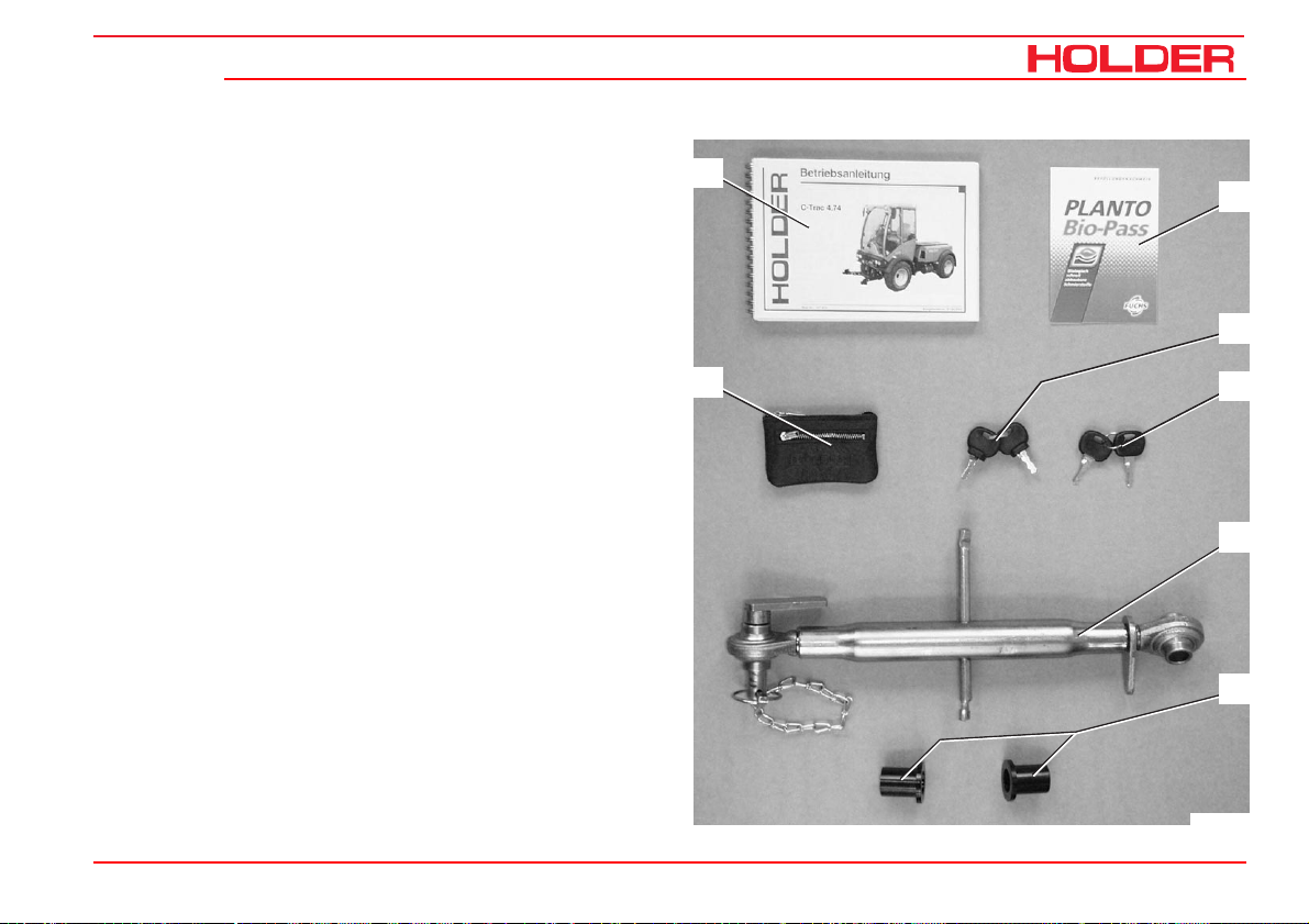
C 4.74
Accessories
The vehicle is delivered with the following accessories:
1 Operating instructions
2 Bio-pass for certification of filling
with environment-friendly hydraulic oil
3 Key holder
4 Two ignition keys
5 Two door keys
6 Upper link with retaining pins
7 Two reducers for category II implements
Operating instructions
1
3
Description
2
4
5
6
7
Bild_C265
149 443 43
Page 45

Page 46

C 4.74
Operating instructions
Taking into operation
Daily checks and services prior to taking
into operation
If damage or defects are found during the following checks,
they must be eliminated before taking the vehicle into service. Do not operate the vehicle before proper repairs are
carried out. Safety and protective devices should not be
removed or disabled. Fixed specified settings may not be
changed.
Before starting work, make yourself familiar with all the functions and protective devices of the vehicle.
Check and clean the cooler and debris screens
NOTE
- Check if the debris screens (2,3 and 4)
are clean.
- Clean the screens if necessary.
The screen (3) can be pulled out laterally to the left after removing the two
screws and then cleaned easily.
- The air intake of the air cleaner (1) must
be clean.
2
3
4
Bild_C154
1
Bild_C155
149 443 45
Page 47

Operating instructions
Taking into operation
Turn on the battery isolating switch
NOTE
The battery can be switched off completely
with the removable key.
- Insert the key (1) into the battery isolating switch and
turn it to the vertical position.
The battery circuit is turned on.
Check the engine oil level
NOTE
Check the engine oil level only when the vehicle is on level ground.
- Let the engine run approx. 2 minutes with the heater
temperature control open.
- Stop the engine and pull the oil dipstick (1) out after
about 1 minute.
- The oil level should be between the minimum and
maximum marks.
- Top up oil as specified in the maintenance instructions.
C 4.74
1
Bild_C157
1
ATTENTION
Do not fill too much oil.
Bild_C227
46 149 443
Page 48

Operating instructions
C 4.74
Check the trailer hitch (option) if required
- Check the trailer hitch for proper condition and opera-
tion. Carry out the check according to the instructions
in the section “Operating the trailer hitch“.
Check the tire inflation pressure
NOTE
Your vehicle can be equipped with different types
of tires. The specified inflation pressure for your
tires is given in the table entitled “Tires“ in the
technical data section.
- Check the inflation pressure at all four tires. All tires must
have the same pressure. The rolling resistance increases
if the pressure is too low. This causes an increase in fuel
consumption and tire wear, the driving characteristics
become poorer.
DANGER
If the inflation pressure is too high, the tires
can explode.
Taking into operation
Bild_C230
- The tires should not be damaged or worn.
- Have damaged tires replaced without delay. Due to the
longer braking distance the risk of an accident is increased.
149 443 47
Bild_C225
Page 49

Operating instructions
Taking into operation
Check the hydraulic oil level
- Raise the dump body (dumper).
- Retract all hydraulic cylinders.
- Withdraw the oil dipstick (1).
- The oil level must be at the marking (2).
- Top up oil as specified in the maintenance instructions.
C 4.74
1 2
Bild_C226
48 149 443
Page 50

C 4.74
Filling fuel
- If necessary, read the fuel level (1) on the multifunc-
tional display.
CAUTION
Danger of fire when handling fuels. Turn off
the engine. Do not fill any fuels in the vicinity
of naked flames, ignition sparks or hot engine parts. Do not smoke when refuelling.
- Remove the oil filler cap (2) of the fuel tank.
- Top up diesel fuel as specified in the maintenance
instructions.
Operating instructions
Taking into operation
1
Motor
1
2
Km/h
digital system
15
10
FRONT
5
0
0000000 h
540U/min
1000U/min
RPMx100
PTO
electronic
20
25
30
Bild_C219
Filling capacity ............................................ approx. 60 L
2
- Refit the filler cap (2).
Bild_C158
149 443 49
Page 51

Operating instructions
Taking into operation
Check the brake fluid level
- Check the brake fluid level at the brake fluid reservoir
(1).
- The brake fluid level should be between the minimum
and maximum marks on the reservoir.
- Top up brake fluid as specified in the maintenance
instructions.
Adjust the steering wheel
NOTE
The angle of the steering wheel can be set to
a comfortable position.
DANGER
Do not adjust the steering wheel while driving.
C 4.74
1
3
2
Bild_C159
- Loosen the lever (2).
- Adjust the angle and height of the steering wheel (3).
- Retighten the lever (2).
2
50 149 443
Bild_C160
3
Page 52

C 4.74
Adjust the driver’s seat with mechanical suspension
DANGER
Do not adjust the seat while driving. Risk of
accidents!
1 Horizontal adjustment
- Raise the handle (1) and push the seat to the front
or rear.
- Release the handle and allow the seat lock to
engage.
2 Weight adjustment
- Adjust the desired driver’s weight by turning the
weight adjustment lever (2).
- If the adjustment is correct, the position set at the
height adjustment handle (4) is indicated in the
window (3).
3 Height adjustment
- Three different heights can be set with the handwheel (4).
- The weight should be adjusted after each height
adjustment.
Operating instructions
Taking into operation
Bild_C024
NOTE
To prevent damage to your health, the individual adjustment should be checked and
adjusted before taking the vehicle into service.
1
2
43
149 443 51
Page 53

Operating instructions
Taking into operation
Adjusting the driver’s seat with pneumatic suspension
1 Backrest
2 Adjustment knob for lumbar padding
3 Backrest inclination
4 Weight adjustment
5 Horizontal cushioning
6 Horizontal adjustment
DANGER
Do not adjust the seat while driving. Risk of
accidents!
C 4.74
1
2
- Adjust the seat so that all controls can be reached
and operated safely.
NOTE
Observe the operating instructions for the
seat supplied with your vehicle.
Adjusting the lumbar padding
- Be seated on the seat and lean against the backrest
(1).
- Turn the adjustment knob for lumbar padding (2) until
the most comfortable position is reached.
52 149 443
Bild_010
Adjusting the backrest inclination
- Pull the inclination lever (3) up.
- Adjust the inclination of the backrest with your back.
- Release the inclination lever.
456
3
Page 54

C 4.74
Adjusting the driver’s weight
- Sit down on the driver’s seat.
- Pull the weight adjustment handle (4) up.
NOTE
An alarm sounds. The seat is automatically
set to the weight of the driver; the alarm
ceases.
- Release the lever.
Adjusting the horizontal suspension
- Pull the horizontal suspension lever (5) back:
Seat suspension is free in the horizontal direction.
- Pull the horizontal suspension lever (4) forward:
Seat suspension is locked in the horizontal direction.
Adjusting the seat horizontally
- Pull the horizontal adjustment lever (6) up.
- Slide the seat horizontally to the front or rear to the
suitable seat position.
- Release the horizontal adjustment lever.
Operating instructions
Taking into operation
1
Bild_010
2
456
3
149 443 53
Page 55

Operating instructions
Taking into operation
Filling washing water
NOTE
The washing water reservoir for the windshield
washer is located behind the driver’s seat.
- Open the filler cap (1) and add washing water into the
reservoir (2).
Filling quantity .......................................... approx. 1.3 L
Check the lights and rear view mirror
C 4.74
1 2
- Check the lights for proper operation. Carry out the
check according to the instructions in the section
entitled “Lights“
- Adjust the rear view mirror so that the roadway behind
the vehicle and the working area are easily seen.
54 149 443
Bild_C161
Bild_C231
Page 56

C 4.74
Operating instructions
Taking into operation
Starting the engine
Notes on the engine before starting up
DANGER
Do not start or run the engine in enclosed
spaces. Danger of poisoning through exhaust
gases!
Notes on starting
CAUTION
Before starting, make sure no-one is in the
vicinity of the vehicle.
ATTENTION
Do not use any starting aids such as Startpilot
or similar products. Turn off the drive or driven
attaching implements.
CAUTION
Start the engine only from the driver’s station.
149 443 55
Page 57

Operating instructions
Taking into operation
Start the engine
- Set the forward/reverse selector switch (1) to the
neutral position (centre).
- Fully depress the inching pedal (2).
NOTE
The engine can only be started if the pedal is
fully depressed (starting safety switch).
- Set the hand throttle button (4) to idle (push in fully).
- Insert the ignition key and turn the preheat/starter
switch (3) to position 1.
C 4.74
1
3
2
Bild_C162
NOTE
The battery charging indicator (6), engine oil
pressure indicator (7), parking brake indicator come on (8) (if parking brake is applied).
56 149 443
4
Bild_C163
Page 58

C 4.74
- Turn the ignition key to position 2.
The engine is being preheated. The preheating indicator (5) comes on.
NOTE
When starting at low temperatures, hold the
ignition key longer (approx. 1 minute) in position 2.
- When the preheating indicator extinguishes, turn the
ignition key to position 3 to start the engine.
The engine starts.
ATTENTION
Operate the starter for a maximum of 20 seconds. Wait one minute before repeating the starting procedure. Repeat the star ting procedure only
twice at most. In case the engine does not start,
carry out a troubleshooting according to the
section entitled “Troubleshooting guide“.
- Release the ignition key after the start.
The battery charging indicator (7) and the engine oil
pressure indicator (6) extinguish.
- Set the engine speed with the hand throttle button or
accelerator pedal to the desired rpm (9).
- The hour meter (10) is activated.
Operating instructions
Taking into operation
5 96
8 10
7
Motor
1
2
Km/h
digital system
15
10
FRONT
5
0
0000000 h
540U/min
1000U/min
RPMx100
PTO
electronic
20
25
30
Bild_C164
149 443 57
Page 59

Operating instructions
Taking into operation
Check the brakes and steering for proper operation
- Make a short trial run and check the steering and
brakes for proper operation.
DANGER
Do not drive a vehicle with a defective steering and/or braking system.
C 4.74
58 149 443
Page 60

C 4.74
Operation
Before starting to drive
Operating instructions
When driving on public highways, observe the rules and
regulations of the highway code.
Driving safety rules
• Drive the vehicle only from the driver’s station with
the cab doors closed.
• Always adjust your speed to the driving conditions
and the load you are carrying.
• Never drive downhill without having the vehicle in gear
or with the engine stopped.
• Before driving, check that no-one is standing in the
immediate vicinity of the vehicle.
• The driving behaviour of the vehicle is strongly
affected by the weight and swing range of the implements, trailers and, if fitted, ballasting. Therefore
drive slowly with heavy equipment and take the longer
braking distance into consideration.
149 443 59
• When following a curve with a trailer or other implements,
do not forget to take the added length and drag into
consideration.
DANGER
Any parts of the implements posing a traffic
hazard must be covered before driving or
identified with warning signs.
• Switch off the differential lock in curves.
• When driving on slopes, always drive straight downhill
if possible; if you have to turn, turn only uphill.
• On steep slopes you can improve traction by activating the differential lock.
• Drive across slopes only in accordance with the notes
at the end of this chapter.
Page 61

Operation
Operating instructions
C 4.74
Driving
Driving with hydrostatic drive and digital electronics
- Start the engine.
- Preselect the direction of travel with the direction
switch (1).
- Pull up the forward/reverse selector switch (1) and
move it to the front or rear (forward or reverse).
NOTE
After starting the engine, the forward/reverse
selector switch must be operated once if it
was in the forward or reverse position when
starting. This prevents any accidental movement of the vehicle when starting the engine.
NOTE
You can also select the new direction when
travelling at reduced speed.
CAUTION
The vehicle will brake strongly and accelerate in the opposite direction.
1
Bild_C165
60 149 443
Page 62

C 4.74
Table of driving ranges
- Select the desired driving program with the driving
program switch (2). The selected position is illuminated:
You can select between 4 programs:
Range 1 and 2 eg on-road travel
Range 3 and 4 eg working
Operating instructions
Operation
321
Bild_C166
149 443 61
Page 63

Operating instructions
C 4.74
Operation
Table of driving programs*
Position Symbol Function Utilisation
Range 0 STOP Drive off
Range 1 Rabbit symbol Maximum speed eg for highway driving
Range 2 Turtle symbol Reduced speed eg for slow on-road travel
Range 3 PTO symbol Travel speed adjustable with fine
adjustment knob, is controlled
automatically in case of high power
demand of implement
Range 4** Snow blower symbol Travel speed adjustable with fine
adjustment knob, is controlled
automatically in case of high power
demand of implement
* The driving programs can be optimised for special operations by your Service, eg controlled constant driving speed
** With SDS driving comfort, the vehicle speed is controlled with the accelerator.
eg for mowing
eg special setting for snow
blower
62 149 443
Page 64

C 4.74
Selecting on-road travel (transport speed)
The vehicle is stationary.
- Set the program switch (2) to range 1 or 2.
NOTE
The driving range can also be switched while
driving at reduced speed.
- Release the parking brake.
- Depress the accelerator pedal for the desired speed.
The vehicle starts and can be driven up to the maximum speed of the chosen range.
- You can read the engine speed (5) and driving speed
(4) on the multifunctional display.
Setting the working speed of programs 3 and 4
Operating instructions
4
Operation
321
Bild_C166
5
NOTE
With programs 3 and 4 you can select the
driving speed independent of the PTO rpm.
Motor
5
1
2
Km/h
digital system
15
10
FRONT
0
0000000 h
540U/min
1000U/min
RPMx100
PTO
electronic
20
25
30
Bild_C167
149 443 63
Page 65

Operating instructions
Operation
The vehicle is stationary.
- Set the fine control knob (1) to 0.
- Set the program switch (2) to range 3 or 4.
- Adjust the PTO rpm with the hand throttle (3).
NOTE
The engine speed must reach at least 1500
rpm as the control is only effective beginning
at this speed.
NOTE
You can also switch ranges while driving.
The ranges 3 and 4 provide a speed as required by the load
on the PTO. This means that if, for example, the snow blower
requires more power when meeting high resistance, the
vehicle will drive more slowly. As the resistance decreases,
the vehicle accelerates again to the previously selected
driving speed. Driving range 4 is especially adapted for certain applications.
C 4.74
321
Bild_C166
- Release the parking brake.
- The driving speed is controlled with the fine control
knob (1).
64 149 443
Page 66

Operating instructions
C 4.74
Adjusting the fine control knob
NOTE
You can adjust the fine control knob (1) at
any time while driving for fine and infinitely
variable control of the driving speed.
- In position 0 the vehicle is stationary. When turned
further clockwise, the vehicle starts driving and at the
maximum scale position 11, the maximum speed of
the driving range is achieved.
- You read can the engine speed and driving speed on
the multifunctional display.
NOTE
In this operating mode, the vehicle drives
automatically and needs only to be steered.
This mode is best for operating an implement as you can
concentrate fully on controlling the implements.
Operation
321
Bild_C166
149 443 65
Page 67

Operating instructions
Operation
Driving with SDS (Special Drive System)
For setting programs 1-3 with the program switch (2) see
the operation section on pages 61 and 62.
Driving program 4 (SDS)
- Set the program switch (2) to driving range 4.
NOTE
At this level the fine control knob (1) is not
working. The function is assumed by the pedal
(4).
- Adjust the engine rpm with the hand throttle (3).
- You can now control the vehicle speed steplessly with
the pedal (4) (accelerator).
C 4.74
321
Bild_C166
4
Bild_C168
66 149 443
Page 68

C 4.74
Operating the inching pedal
7 Inching pedal
8 Accelerator pedal
This function is active for all driving programs.
Operating instructions
Operation
NOTE
The inching pedal allows driving speed to be
reduced temporarily.
- Depress the inching pedal (7) to reduce driving speed
and to stop completely.
- Release the inching pedal again after passing the
obstacle.
The vehicle will resume the previously selected
speed.
Changing the direction of travel
- Preselect the new direction with the forward/reverse
selector switch (9).
- The vehicle will come to a standstill and accelerate
again in the opposite direction.
149 443 67
7
9
8
Bild_C169
Bild_C170
Page 69

Operating instructions
Operation
Engaging the differential lock
NOTE
With the differential lock you can improve traction on soft, slippery ground. The engine
speed should be over 1000 rpm during its use.
You can engage the differential lock only
briefly by toggling the switch momentarily.
ATTENTION
The differential lock may only be used when
driving straight ahead.
C 4.74
1
Bild_C276
- Depress the rear end of the differential lock switch (1)
and hold it.
2
The indicator (2) in the multifunctional display lights
up red. An intermittent alarm sounds at the same
time.
The differential lock acts on both axles.
Disengaging the differential lock
- Release the differential lock switch (1).
The indicator (2) goes out and the alarm in the multi-
Motor
5
1
2
Km/h
digital system
15
10
FRONT
0
0000000 h
540U/min
1000U/min
RPMx100
PTO
electronic
20
25
30
functional display ceases.
Bild_C172
68 149 443
Page 70

Operating instructions
C 4.74
Steering
The vehicle has a hydraulically-operated articulated steering. The wheels also stay in track in curves so that implements are guided without any lateral offset.
Steering
- Turn the steering wheel (1) in the desired direction.
The possible turning radii depend on the tires and track widths
of your vehicle. For exact information refer to the track width
table in the section „Technical data“.
Two-stage steering*
Operation
2
1
Bild_C173
The vehicle can be driven with two steering speeds.
- Indirect steering (travel mode- slow steering speed)
- Direct steering (working mode - fast steering speed)
- Depress the toggle switch (2) on the left. The indica-
tor light in the toggle switch comes on and the steering for the working mode is turned on.
* Option
149 443 69
NOTE
With direct steering the steering lock is about
twice as large as with indirect steering for
the same steering movement.
(ratio approx. 1:2)
ATTENTION
For on-road travel the two-step steering must
be set to indirect steering (indicator light off)
(danger).
Page 71

Operating instructions
Operation
Brakes
The service brake is a drum brake mounted in the front axle
and it is actuated hydraulically. The parking brake is applied
with the parking brake switch.
Applying the service brake
- Depress the brake pedal (1).
Applying the parking brake
ATTENTION
The parking brake is not intended to be used
for braking while driving.
- Unlock the lock at the parking brake switch (2) and
depress the switch to the left.
The parking brake is applied and the indicator light in
the switch and the parking brake warning light (3) in
the multifunctional display come on.
C 4.74
2
1
3
15
Motor
1
2
Km/h
digital system
10
540U/min
FRONT
5
0
1000U/min
RPMx100
PTO
electronic
0000000 h
Bild_C174
20
25
30
Bild_C175
70 149 443
Page 72

C 4.74
Releasing the parking brake
- Turn off the parking brake switch (2).
The parking brake is released and the indicator light in
the switch and the parking brake warning light (3) go
out.
- If the parking brake warning light (3) in the multifunc-
tional display comes on with the parking brake released, there is too little pressure for releasing the
parking brake in the pressure accumulator.
- Start the engine to build up pressure to release the
parking brake.
ATTENTION
An alarm is sounded when driving with the
hand brake applied.
Operating instructions
2
3
Motor
1
2
Km/h
digital system
Operation
1
15
10
540U/min
FRONT
5
0
1000U/min
RPMx100
PTO
electronic
0000000 h
Bild_C174
20
25
30
Bild_C175
149 443 71
Page 73

Operating instructions
Operation
Driving on slopes
DANGER
Driving on slopes is dangerous as the vehicle can tip over if the centre of gravity exceeds the tip-over limit on an extreme slope.
The following factors reduce the hazard:
- small or no load
- low driving speed
- low gradient
- low tire inflation pressure
NOTE
The driving comfort and the traction of the
vehicle can be improved by reducing the inflation pressure.
- large track width
- level, non-bumpy terrain
When turning on slopes we recommend proceeding as
shown in the drawing on the right.
C 4.74
Uphill
72 149 443
Page 74

C 4.74
Operating instructions
Special operating instructions
Stationary operation
The vehicle can be used for stationary operation, for example,
to drive a water pump via the PTO shaft.
ATTENTION
Place the vehicle n level ground in both directions.
- Attach the stationary equipment to the PTO shaft (1).
- Set the program switch to 0.
- Operate the parking brake.
DANGER
Before switching on the PTO, make sure noone is standing in the vicinity of the vehicle
and the rotating PTO shaft.
1
Bild_C232
Removal of hydraulic oil for stationary operation
When the vehicle is stationary, hydraulic oil can be removed,
for example, for the operation of a hydraulic dump.
Max. quantity of oil removed .................................. 12 L
ATTENTION
Before starting to drive after stationary operation, first check if the power steering is working. Turn the steering wheel fully to the right
and left several times to release air from the
steering system.
149 443 73
Page 75

Operating instructions
Special operating instructions
Adjusting the track width
You can adjust the track width of the vehicle by mounting
the wheels inside out.
DANGER
Observe the safety notes on a safe shutdown
and jacking up for the wheel change in the
maintenance instructions.
- Remove the wheels. Turn the wheels inside out, or
from the left to the right.
NOTE
The arrows on the tires must show in the forward direction of rotation again.
- Tighten the wheel nuts to the specified torque.
Torque................................................................. 215 Nm
C 4.74
74 149 443
Page 76

C 4.74
Operation in winter
Operating instructions
Special operating instructions
Oil preheating*
Before starting the engine at temperatures below -20°C, turn
on the heating element* to preheat the oil.
- Connect the preheating system plug to a 230 VAC source.
Observe the operating instructions of the battery manufacturer.
Winter diesel fuel
Whenever temperatures fall below 0°C, use winter diesel or
super diesel fuel or additives recommended in the maintenance instructions.
Engine oil for winter operation
Fill engine oil with a suitable SAE class as recommended
the maintenance instructions.
The cold start capability of the engine can be reduced if the
temperature limits are underrun occasionally, but this does
will not damage the engine.
Hydraulic system
The hydraulic functions are sluggish and slower during cold
temperatures. Bring the hydraulic system to operating temperature with some movements without a load.
* Option
Putting on snow chains
Snow chains can be mounted on the tires to improve grip.
In the following table you will find the order numbers for
RUD chains which fit on the listed tires. You can also fit
snow chains from other manufacturers if these have the
proper dimensions.
Tires Snow chain type
(RUD Order No.)
10.5-18 MPT / 10.5/80-18 22 553 and 24 553
275/70 R18 / 320/65 R18 24 553
31x11.50 R15 22 055
31x15.50-15 Terra 24 548
33x12,50 R15 22 167 and 24 167
33x15.50-15 22 174
36x13.5-15 24 178
Ballast weights
The weight of the machine can be increased with ballast
weights. The same ballast weights must be mounted on
each axle and side.
149 443 75
Page 77

Page 78

C 4.74
Operating instructions
Operating the implements
We have tested and approved a large number of possible
implements for use with this vehicle. Only implements with
the CE symbol may be used. We recommend contacting
our customer service before installing special equipment.
Possible implements
For example for:
vineyards and orchards
agriculture
mowers
snow fighting equipment
and other street cleaning equipment.
Safety instructions for handling implements
The vehicle must be parked safely before the installation of
implements.
It must be secured against rolling, for example, with the parking brake or, if required, with chocks.
DANGER
Be careful when attaching implements: risk of
injury by pinching and shearing parts.
DANGER
No persons are allowed to stand between the
vehicle and implement when the vehicle is not
secured against rolling.
For driving on roads the implement must be
lifted and secured against lowering.
Observe the applicable safety regulations for
your implement. Observe the operating instructions and the safety rules for your implement.
DANGER
During work breaks, the implement must always be lowered to the ground in order to
relieve the hydraulic cylinders. Accidents can
occur if the lowering is uncontrolled, for example, due to damage or accidental movement of the control levers.
DANGER
Any parts of the implements posing a traffic
hazard must be covered before driving or
identified with warning signs.
149 443 77
Page 79

Operating instructions
Operating the implements
Additional information on implements
Do not exceed the permissible total weight,
the permissible axle loads and tire carrying
capacities of the vehicle when installing implements on the front and rear 3-point lift. The
front axle of the vehicle must always be loaded
with at least 20 % of the vehicle’s kerb weight.
Before purchasing equipment, make sure these
conditions are met by performing the following
calculations or by weighing the vehicle-equipment combinations.
Determining the total weight, axle loads and tire carrying capacity including the minimum ballasting.
For their calculation you need the following data:
C 4.74
a (m) Clearance between centre of gravity
of front implement/front ballast and
centre of front axle
b (m) Vehicle wheelbase
c (m) Distance between centre of rear axle
and centre of lower link ball
d (m) Distance between centre of
lower link ball and centre of gravity of
rear implement/rear ballast
1)
See technical data in the operating instructions
2)
See price list and/or operating instructions of the implement
3)
Measure
2) 3)
1) 3)
1) 3)
2)
TL(kg) Kerb weight of the vehicle
TV(kg) Front axle load of the empty vehicle
TH(kg) Rear axle load of the empty vehicle
GH(kg) Total weight of
rear implement/rear ballast
1)
1)
1)
2)
G
v
T
v
T
H
G
H
GV(kg) Total weight of
front implement/front ballast
2)
abcd
78 149 443
Page 80

C 4.74
Rear implement or front/rear combinations
Operating instructions
Operating the implements
1) Calculation of the minimum front ballasting GV
G
·
(c+d)-TV·b
min
H
=
a+b
G
V
+0.2·
TL·b
min
Enter the calculated minimum ballasting required for the
front of the vehicle in the table.
Front implement
2) Calculation of the minimum rear ballasting G
GV ·a-T
G
=
H
min
·b+
H
b+c+d
X·T
·
b
L
H min
Enter the calculated minimum ballasting required for the
rear of the vehicle in the table.
(Value X for Holder vehicle 0.25 4-wheel)
3) Calculation of the actual front axle load T
(If the minimum front ballasting (G
V min
V tat
) is not obtained with
the front implement (GV) , the weight of the front implement
must be increased to the weight of the minimum front
ballasting.)
GV ·(a+b)+TV·b-GH·(c+d)
T
=
V
tat
b
Enter the calculated actual and the permissible front axle
load specified in the operating instructions of the vehicle in
the table.
4) Calculation of the actual total weight G
(If the required minimum rear ballasting (G
tained with the rear implement (G
H min
tat
) is not ob-
H min
), the weight of the rear
implement must be increased to the weight of the minimum
rear ballasting.)
G
=
GV +TL+G
tat
H
Enter the calculated actual and the permissible total weight
specified in the operating instructions of the vehicle in the
table.
5) Calculation of the actual rear axle load TH
T
=
G
-
H tat
T
tat
V tat
tat
Enter the calculated actual and the permissible rear axle
load specified in the vehicle operating instructions in the
table.
149 443 79
Page 81

Operating instructions
Operating the implements
6) Tire carr ying capacity
Enter the double value (two tires) of the permissible tire
carrying capacity (eg see tire manufacturer documentation)
in the table.
C 4.74
Specified Permissible
Actual Calculated Weight
Minimum ballast at
front/rear
Total weight kg
Front axle kg
Rear axle kg
The minimum ballasting must be mounted on the tractor either as attachment or ballast weight!
The calculated weights must be lower than/equal to (
80 149 443
/ kg -
Weight acc. to operating
instructions
≤
≤
≤
) the permissible weights!
≤
kg
kg
kg
Double Permissible Tire
Load Capacity
(Two Tires)
-
-
≤
≤
kg
kg
Page 82

Operating instructions
C 4.74
Attaching implements
The various implements are attached to the front or rear
power lift*.
There are 2 different fastening categories:
Category I Pin diameter 22 mm
Category II Pin diameter 28 mm
The vehicle can be adjusted to both categories by adjusting
the pintle hook bars and providing the pintle hooks with or
without reducer sleeves.
DANGER
Only use the following specified devices for
attaching your implement.
Secure the implement against shifting or rolling.
Operating the implements
* Option
149 443 81
Page 83

Operating instructions
Operating the implements
Adjusting the pintle hooks and pintle hook bars
You can adjust the pintle hooks laterally and longitudinally.
- Measure the stand-off of the pins on your implement.
- Loosen the clamping screws (6) on both sides.
- Slide the pintle hooks laterally until the required
distance is reached.
- Retighten the clamping screws.
- Equipment of category IIcan be attached with the
pintle hooks (5) directly.
- For equipment of category I install the reducing
sleeves on the left and right side.
Adjusting the length of the pintle hook bar
- Loosen the 2 locknuts and clamping screws (inside
and at bottom) on the lower link (2).
- Pull the retaining clip out of the pin (1) and remove
the pin.
- You can put the pintle hook bar (3) in one of 3 positions.
- Insert the pin (1) in the hole and secure with the
retaining clip.
- Retighten the locknuts and clamping screws.
DANGER
Make sure no-one is standing between the
vehicle and implement.
- Drive the vehicle to the implement to be attached.
C 4.74
2
1
6
1 Pin with retaining clip 4 Catch
2 Lower link support 5 Pintle hook
3 Pintle hook bar 6 Clamping screw
(adjustable) with 3 positions
Hole Position Used for
1st hole Front Category I and II
2nd hole Centre Category I
3rd hole Rear Optional attachments
- Steer the pintle hooks (5) under the attaching pin of the
implement.
- Raise the front power lift until the catch (4) closes and
engages.
3
4
5
Bild_C233
82 149 443
Page 84

Operating instructions
C 4.74
Adjusting the upper link
The upper link can be secured at different holes. The required height depends on your implement (for a better adaptation of the equipment, to increase the lifting force and
depending on the lifting height).
Upper hole
• More lifting power, lower lifting height.
Lower hole
• Lower lifting power, higher lifting height.
ATTENTION
The equipment must not hit the cabin.
Operating the implements
1
5
4
2 3
Bild_C268
1 Retaining clip
2 Top link
3 Top link pin
4 Toggle
5 Locking lever
- Secure the top link (2) with the pin (3) and secure the
pin with the retaining clip (1).
- Adjust the top link (2) to the required length (by turning
the toggle (4) to screw it in or out); secure the top link
with the locking lever (5).
149 443 83
ATTENTION
Both threads must be screwed in equally far.
Page 85

Operating instructions
Operating the implements
Connecting hydraulic lines
ATTENTION
The hydraulic couplings on the vehicle must
not carry any pressure before the connection
is made. The couplings on the vehicle and
the hydraulic hoses must be clean.
NOTE
Each implement has different functions and
hydraulic lines to the control unit. Observe
the operating instructions supplied with your
implement and make yourself familiar with
the functions and colour codes.
- Open the protective caps of the hydraulic couplings (1).
- Attach the colour coded hydraulic hoses (2) of the
implement to the hydraulic couplings of the same
colour on the vehicle.
C 4.74
1
2
Bild_C266
ATTENTION
The hydraulic male couplings fit on each coupling and can therefore be connected incorrectly.
With the connection you decide which function/movement of the implement is actually
to be performed with the control lever assigned to the coupling.
84 149 443
DANGER
If you are not sure about the functions, determine them by making trials at a safe place.
Page 86

Operating instructions
C 4.74
Installing the cardan shafts
Only use shafts suitable and intended for the implement.
These shafts are supplied with the implement. The length
the of the shaft must be adjusted before the first installation. In case of doubt, please contact our after-sales service. Observe installation instructions for the cardan shaft
when installing it.
DANGER
Shut off the engine before the installation. Fit
the protective devices as specified after the
installation.
Removing implements
- Drive the implement to its storage place and lower it
with the front power lift.
- Stop the engine, but do not turn the ignition off.
- Operate all control levers for the front power lift several
times in all directions. This will relieve the pressure in
the hydraulic system.
- Slide the outer ring of the hydraulic couplings (1) back
and disconnect the hydraulic hoses (2).
- Close the protective caps on the hydraulic couplings
(as with item 4).
- Remove the upper link from the pin of the upper link
support.
- Pull the catches (3) up to release the implement pins.
- Lower the front power lift and drive forward carefully.
Operating the implements
Bild_C234
1
4 2
3
Bild_C267
149 443 85
Page 87

Operating instructions
Operating the implements
Operating the joystick
1 Pushbutton 1 for joystick level 1
2 Pushbutton 2 for joystick level 2
3 Pushbutton 3 for joystick level 3
4 Joystick (joystick level 0 without pushbutton opera-
tion)
5 Main switch for working hydraulic system
NOTE
The joystick controls those functions of the
implements which are connected to the front
or rear hydraulic couplings. The couplings and
notice plates for the joystick are colour coded,
ie the colours and the function are matched.
C 4.74
32
1
5
The function of the joystick can only be carried out if the
main switch (5) is turned on.
4
Bild_C176
DANGER
Due to the variety of implements and connections, however, we recommend a trial run
of the movement at a safe place without danger to persons or risk of material damage
before starting operation.
86 149 443
NOTE
The joystick can be operated forward and
back as well as to the right and left: The functions are shown on the notice plate.
Page 88

C 4.74
Joystick operation
(Proportional, for sensitive operation).
Joystick direction
Longitudinally (forward / back) Across (left / right)
Joystick level 0
(without button)
Joystick level 1
(with button 1 pressed)
Joystick level 2
(with button 2 pressed)
Joystick level 3
(with button 3 pressed)
Front power lift Y0
Forward: lowering
Back: lifting
Float position on keyboard
Dumper / rear power lift * Y1
Forward: lowering
Back: lifting
Float position Y1 on keyboard 1
Front left quick coupling Y2
No float position planned
Tilting front power lift Y3
(included in front power lift)
Forward: tilt to the right
Back: tilt to the left
Operating instructions
Operating the implements
Front right quick coupling X0
Float position X0 on keyboard 2
Front right quick coupling X1
Float position X1 on keyboard 3
Rear left quick coupling X2
No float position planned
Sideshifting of front power lift X3
Alternative: quick coupling
Left: swing to the left
Right: swing to the right
* Selectable with 3-port cock
149 443 87
Page 89

Operating instructions
Operating the implements
Operating the front power lift
The following movements are possible:
Turn on the main switch (5) for working hydraulics.
- Push the joystick (4) forward.
• The front power lift (implement) is lowered.
C 4.74
32
1
4
You can stop the movement by releasing the joystick.
- Pull the joystick (4) back.
• The front power lift (implement) is raised.
The float position is turned on with the keyboard.
- To turn it on, press button (6). The red LED comes
on.
• The float position of the front power lift is
turned on, ie the implement can be moved by
external force.
- Press button (6) to turn it off. The red LED goes off.
Tilting the front power lift
- Hold button (3) depressed and push the joystick (4)
forward.
• The front power lift tilts to the right.
88 149 443
5
6
- Keep button (3) depressed and pull the joystick (4)
back.
• The front power lift tilts to the left.
Sideshifting the front power lift
- Hold button (3) depressed and push the joystick (4)
forward.
• The front power lift pivots to the right.
- Hold button (3) depressed and push the joystick (4)
forward.
• The front power lift pivots to the left.
Bild_C177
Page 90

C 4.74
Operating the front power lift with keyboard
The following movements are possible:
Turn on the main switch (3) for working hydraulics.
- Keep button (4) depressed for about 1 second. The
red LEDs (5 and 2) come on for about 5 seconds.
• The front power lift (implement) is raised
until the LEDs go off.
Operating instructions
Operating the implements
2 31
4
You can stop the movement by pressing the button (4,7) or
by moving the joystick.
- For lowering press button (7) for about 1 second. The
red LEDs (6 and 2) come on.
• The front power lift (implement) is lowered until the
LEDs go off.
The lifting and lowering speed can be adjusted with the set
knob (1).
- Turn rotary knob (1) to the left - slower.
- Turn rotary knob (1) to the right - faster.
149 443 89
9
678 5
You can also select the float position:
- For selection press button (9) for about 1 second. The
red LED (8) comes on.
• The float position of the front power lift is
turned on, ie the implement can be moved by
external force.
- Press button (9,7 or 4) or move the joystick to turn it
off. The red LED (8) goes off.
Bild_C178
Page 91

Operating instructions
Operating the implements
Switching the front power lift to double-acting
The front power lift can be switched from single-acting to
double-acting.
C 4.74
32 41
- To switch to double-acting press button (5). The red
LED (6) goes off.
- To switch to single-acting toggle button (5). The red
LED (6) comes on.
NOTE:
The front power lift is always single-acting
when the vehicle is started or when the main
switch for the working hydraulic system is
turned on.
Operating the tilting device with the keyboard
- Keep button (4) depressed.
• The front power lift tilts to the right.
You can stop the movement by releasing the button.
- Keep button (3) depressed.
• The front power lift tilts to the left.
90 149 443
- Press button (1). The red LED (2) comes on.
• The float position of the tilting device is turned on,
ie the implement can be moved by external force.
- Press button (1,3 or 4) or move the joystick to turn it
off. The red LED (2) goes off.
6
Bild_C179
5
Page 92

C 4.74
Operating the sideshift with the keyboard
- Keep button (4) depressed.
• The front power lift pivots to the right.
You can stop the movement by releasing the button.
- Keep button (3) depressed.
• The front power lift pivots to the left.
- Press button (1) for about 1 second. The red LED (2)
comes on.
• The float position of the sideshift is turned on, ie
the implement can be moved by external force.
- Press button (1,3 or 4) or move the joystick to turn it
off. The red LED (2) goes off.
Operating instructions
Operating the implements
32 4 51
Bild_C180
Transport safety
The joystick and keyboard movements can be locked with
the main switch (5):
- Main switch off - joystick movement and keyboard
disabled
- Main switch on - joystick movement and keyboard
enabled
149 443 91
NOTE
When joystick movement is disabled, you can
prevent the implement from being moved
through unintentional contact with the joystick
or keyboard.
Transport lock for on-road travel.
Page 93

Operating instructions
Operating the implements
External operation of the front power lift
The front power lift can be operated from outside the cab.
C 4.74
ATTENTION
When leaving the cab, set the forward/reverse
selector switch to neutral and apply the parking brake to secure the vehicle against rolling.
- To raise the front power lift push toggle switch (1) up.
The front power lift will be raised as long as the toggle switch
is depressed.
- To lower the front power lift push toggle switch (1)
down.
The front power lift will be lowered as long as the toggle
switch is pushed.
1
Bild_C181
92 149 443
Page 94

Operating instructions
C 4.74
Flow limiter for joystick
1 Button for individual flow limitation for each individual
joystick function.
Operating the implements
21
3
- Turn on the main switch for working hydraulics.
The lifting and lowering speed of the power lift can be stored
individually with the flow limitation.
- Operate the joystick (4) until the desired cylinder
speed is reached, then press button (1).
This value is stored as the maximum speed and it applies
for the full stroke of the joystick.
If the full oil flow is required again, proceed as follows:
- Move the joystick (4) as far as possible and press
button (1).
The full oil flow is released for the full stroke of the joystick.
Toggle button for Float Position Button
2 Button for setting the joystick button (3) to “float
position of front power lift“
149 443 93
- Press the button (2).
The button (3) is now also activated as float position button
for the front power lift.
Its activation is indicated with two flashing LEDs.
NOTE
You can also toggle the float position on and off
with button (3).
Its activation is indicated with the LED (5).
- Press the button (2) again to toggle the switch.
5
4
Bild_C212
Page 95

Operating instructions
Operating the implements
Operating the rear power lift*
The following movements are possible:
Turn on the main switch (5) for working hydraulics.
- Set the switch lever (1) at the rear to the position
„Rear Power Lift“.
- To raise the lift, press button (2) and pull the joystick
(3) back.
• The rear power lift (implement) will be raised.
You can stop the movement by releasing the joystick.
- Press button (2) and push the joystick (3) forward.
• The rear power lift (implement) will be lowered.
C 4.74
1
Bild_C277
The float position is turned on with the keyboard.
- To turn it on, press button (4). The red LED comes
on.
• The float position of the rear power lift is turned
on, ie the implement can be moved by external
force.
- Press button (4) to turn it off. The red LED will go off.
* Option
94 149 443
2
4
3
Bild_C213
Page 96

C 4.74
External operation of the rear power lift*
The rear power lift can be operated from outside the cab.
ATTENTION
When leaving the cab, set the forward/reverse
selector switch to neutral and apply the parking brake to secure the vehicle against rolling.
- To raise the rear power lift push toggle switch (1) up.
Operating instructions
Operating the implements
1
The rear power lift will be raised as long as the toggle switch
is depressed.
- To lower the rear power lift push toggle switch (1)
down.
The rear power lift will be lowered as long as the toggle
switch is depressed.
* Option
149 443 95
Bild_C271
Page 97

Operating instructions
Operating the implements
Operating the hydraulic couplings
1 Pushbutton 1 for joystick level 1
2 Pushbutton 2 for joystick level 2
3 Pushbutton 3 for joystick level 3
4 Joystick (joystick level 0 without pushbutton opera-
tion)
5 Main switch for working hydraulic system
C 4.74
32
1
4
NOTE
The joystick controls those functions of the
implements which are connected to the front
or rear hydraulic couplings. The couplings and
notice plates for the joystick are colour coded,
ie the colours and the function are matched.
DANGER
Due to the variety of implements and connections, however, we recommend a trial run
of the movement at a safe place without danger to persons or risk of material damage
before starting operation.
96 149 443
5
Bild_C176
The function of the joystick can only be carried out if the
main switch (5) is turned on.
NOTE
The joystick can be operated forward and
back as well as to the right and left: The functions are shown on the notice plate.
Page 98

Operating instructions
C 4.74
Operating the green hydraulic couplings*
- Push the joystick (4) to the left or right.
• The green front right hydraulic couplings will be
supplied with oil.
You can stop the movement by releasing the joystick.
The float position is turned on with the keyboard.
- To turn it on, press button (7). The red LED comes
on.
• The float position of the green hydraulic couplings
is turned on, ie the implement can be moved by
external force.
- Press button (7) to turn it off. The red LED will go off.
Operating the blue hydraulic couplings*
- Press button (1) and move the joystick (4) to the left
or right.
• The blue front right hydraulic couplings
will be supplied with oil.
You can stop the movement by releasing the joystick.
The float position is turned on with the keyboard.
- To turn it on, press button (6). The red LED comes
on.
- Press button (6) to turn it off. The red LED will go off.
* Option
Operating the implements
1
2
67
Operating the yellow and white hydraulic couplings*
- Press button (2) and move the joystick (4) to the left
or right.
• The yellow rear left hydraulic couplings
will be supplied with oil.
- Press button (2) and move the joystick (4) to the left
or right.
• The white front right hydraulic couplings will be
supplied with oil.
NOTE
The yellow and white hydraulic couplings do not
have a float position.
4
Bild_C215
149 443 97
Page 99

Operating instructions
Operating the implements
Turning on the front PTO
DANGER
Before turning on the PTO, make sure noone is standing close enough to the vehicle
and the driven implement to be hurt.
ATTENTION
Check the mounting angle of the cardan shaft.
Do not start it under 1500 rpm.
- Release the lock at the starting safety switch (1) and
depress the switch. The front PTO is turned on.
- To turn it off, depress the safety switch at the top.
NOTE
If the engine temperature is too high, the PTO
will turn off automatically and an alarm will
sound. The engine must cool at idle speed
before being turned off. Restart the engine
after checking for the cause.
DANGER
After the installed implement is turned off, it
can continue to run. Wait until the implement
is stationary before working on it again.
C 4.74
1
Bild_C182
98 149 443
Page 100

Operating instructions
C 4.74
Turning on the rear PTO*
DANGER
Before turning on the PTO, make sure noone is standing close enough to the vehicle
and the driven implement to be hurt.
ATTENTION
Check the mounting angle of the cardan shaft.
Do not start it under 1500 rpm.
- Release the lock at the safety switch (1) and depress
the switch. The rear PTO is turned on.
- To turn it off, depress the safety switch at the top.
Operating the implements
1
Bild_C183
NOTE
If the engine temperature is too high, the PTO
will turn off automatically and an alarm will
sound. The engine must cool at idle speed
before being turned off. Restart the engine after checking for the cause.
* Option
149 443 99
DANGER
After the installed implement is turned off, it
can continue to run. Wait until the implement
is stationary before working on it again.
 Loading...