

Page 1
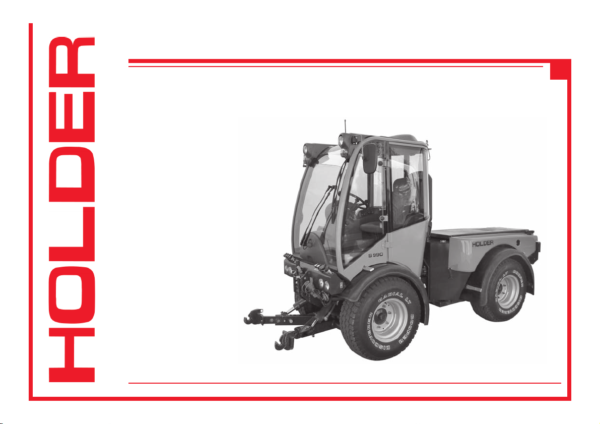
Operating Instructions
C 9.92 H
Order No.: 153 146
Date of Issue: 10.09.2009
Page 2

Page 3

C 9.92
Foreword
Operating Instructions
We congratulate you on having bought a product from
HOLDER. We would like you to be able to work safely with
your tractor and without malfunctions, and therefore we recommend you follow the instructions in this manual. You will
also ensure getting full value from your tractor, save yourself trouble and maintain your warranty. These operating instructions provide you with the required information. These
operating instructions also apply to tractors with the designation 9.92 H.
Continual development
Due to the continual development of our tractor in design
and equipment, there may be deviations between these
operating instructions and your tractor.
Despite taking all the care possible in the creation of this
manual, we can not fully exclude mistakes. Please note
that the technical data, illustrations and descriptions are
not binding and no legal claims can be made on the basis
thereof.
These operating and maintenance instructions are supplied
with each tractor. Keep these in a safe place where they are
available for the driver and owner at any time. It they should
get lost, the owner must get a replacement from the manufacturer.
The personnel entrusted with the operation and maintenance
of the tractors must be made familiar with the operating and
maintenance instructions. The owner must ensure that every
operator has received, read and understood these instructions.
We thank you for reading and observing these instructions.
In case you still have any questions, suggestions for improvements or discovered mistakes, please contact our
customer service.
General notes on service
Detach the warranty card, have it filled in by your dealer
and return the signed card to us.
Have the scheduled services carried out at the proper intervals and have them confirmed with the dealer’s stamp and
signature in these instructions. Please note that warranty
can only be claimed if the regular services have been carried out as scheduled.
153 146 1
Page 4
Operating Instructions
Foreword
In case of questions regarding your tractor, please state the
following data:
Tractor model ..................................................... eg S 990
Engine serial number ................................... eg 10668874
Chassis serial number .................................. eg 53400101
Date of sale,
date of complaint, if necessary .................. eg 15.07.2009
Service hours ................................... eg 500 service hours
Date of issue and version of instructions
C 9.92
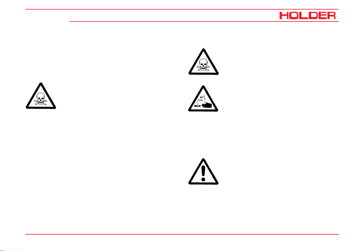
Explanation of the cautions used:
DANGER
Indicates procedures which must be observed
exactly to prevent danger to the life and limbs
of persons.
CAUTION
Indicates procedures which must be observed
exactly to prevent personal injuries.
September 2009
We wish you safe driving and troublefree working with your
HOLDER.
Max Holder GmbH
Max-Holder-Straße 1
72555 Metzingen
Phone 07123 966 - 0
Fax 07123 966 - 228
E-mail: info@max-holder.com
www.max-holder.com
2 153 146
ATTENTION
Indicates procedures which must be observed
exactly to prevent damage to and/or destruction of objects and equipment.
NOTE
For technical exigencies requiring particular
attention.
Page 5

C 9.92
Table of contents
Operating Instructions
Foreword
Chapter PageChapter Page
Foreword ........................................................................ 1
Information on the tractor .............................................. 5
Operating instructions .................................................... 7
Technical data ..............................................................15
Description ................................................................... 27
Taking into service .......................................................45
Operation ......................................................................59
Special operating instructions .......................................75
Operating the attachments ........................................... 79
Other operations ......................................................... 117
Parking the tractor ...................................................... 131
Trailers, towing ........................................................... 133
Transport, hoisting, towing ..........................................137
Indicators, adjustments .............................................. 141
Malfunctions, causes, remedy .................................... 143
General remarks on maintenance ............................... 153
Maintenance schedule ................................................161
153 146 3
Maintenance during the initial period of operation ....... 167
Maintenance after the first 50 service hours ...............167
Maintenance after the first 500 service hours ............. 179
Maintenance as required ............................................. 183
Maintenance every 250 service hours ........................ 193
Maintenance every 500 service hours ........................ 201
Maintenance every 1000 service hours ....................... 203
Maintenance every 1500 service hours ....................... 205
Maintenance every 3000 service hours ....................... 207
Annual maintenance ................................................... 209
Maintenance every 2 years.........................................213
Maintenance every 5 years.........................................215
Taking the tractor out of operation .............................. 217
Coolant, fuel and lubricant specifications ................... 219
Maintenance data ....................................................... 221
Alphabetical index ...................................................... 227
Page 6

Page 7

C 9.92
Information on the tractor
Operating Instructions
This tractor has received the type approval acc. to 74/150/
EEC after a safety inspection. The tractor conforms to the
EMC (Electromagnetic Compatibility) requirements of directive 89/336/EEC. The regulations for exhaust gas identification and noise emissions are observed. The tractor must
be registered and the licence plates must be attached at
the front and rear.
Intended use
The tractor can be used for towing trailers and for the operation of various attachments. The maximum trailer load, which
must not be exceeded, is stated on the identification plate.
The transport of persons is not allowed.
The tractor is designed solely for the customary type of
operation in farming and forestry, the upkeep of municipal
facilities, including operation in winter. The tractor may only
be used as intended and described in these operating instructions.
Included in the intended use is also the performance of the
specified maintenance and repairs.
The tractor, together with its attachments, may only be used,
serviced and repaired by persons familiar with this equipment and who have been warned of possible risks. The applicable safety regulations and any other valid safety, industrial medicine and traffic rules must be observed.
Site of operation
The tractor must be used in the open. Its operation on public
roads is allowed. When using the tractor on public roads,
observe the regulations in your country.
Unintended use
Any use which is not intended as described above is not
allowed. HOLDER can not be held responsible for any hazards which may result from any unintended use. The manufacturer will not be responsible for any damage which may
result therefrom. The damage shall solely be borne by the
user. The tractor may not be used for any other purposes
than those described in these instructions. The transport of
persons on the loading area or attachment is not allowed.
153 146 5
Page 8

Operating Instructions
Information on the tractor
Residual hazards and risks
C 9.92
Despite careful working and conformance with standards and
regulations, hazards arising from handling the tractor can not
be excluded.
The tractor and all other system components conform to
currently applicable safety regulations. A residual risk, however, can not be excluded even if the tractor is used as
intended and all the safety notices given are observed.
For this reason, persons standing in the area of the tractor
and attachments must exercise particular caution in order
to be able to react immediately in case of a malfunction,
incident, failure, etc.
CAUTION
All persons standing in the area of the tractor
and attachments must be advised of the risks
which can result from their operation. Also
read and observe the other safety rules and
regulations contained in these operating instructions.
The hazards can include:
- Unexpected movements the attachments and of the
tractor.
- Escape of fuel, fluids and lubricants due to leaks,
broken lines and containers, etc.
- Risk of accidents when driving, steering and braking
due to unfavourable ground conditions such as
slopes, icy roads, unevenness or poor visibility, etc.
- Falling, stumbling, etc when moving on the tractor,
particularly if it is wet.
- Risk of fires and explosions due to the battery and
electric voltages.
- Danger of poisoning through diesel exhaust fumes.
- Risk of fire through diesel fuel and oils.
- Human misconduct through the non-observance of
safety rules.
Disposal instructions
Your tractor is made of different materials. Each material
should be disposed of/treated/recycled according to different regional/national regulations. We recommend contacting a salvage company.
6 153 146
Page 9

Operating Instructions
C 9.92
Operating instructions
Driver’s licence
For the driving of this tractor you require a driver’s licence
depending on the maximum ground speed and the permissible total weight of the tractor and combinations. See the
tables below.
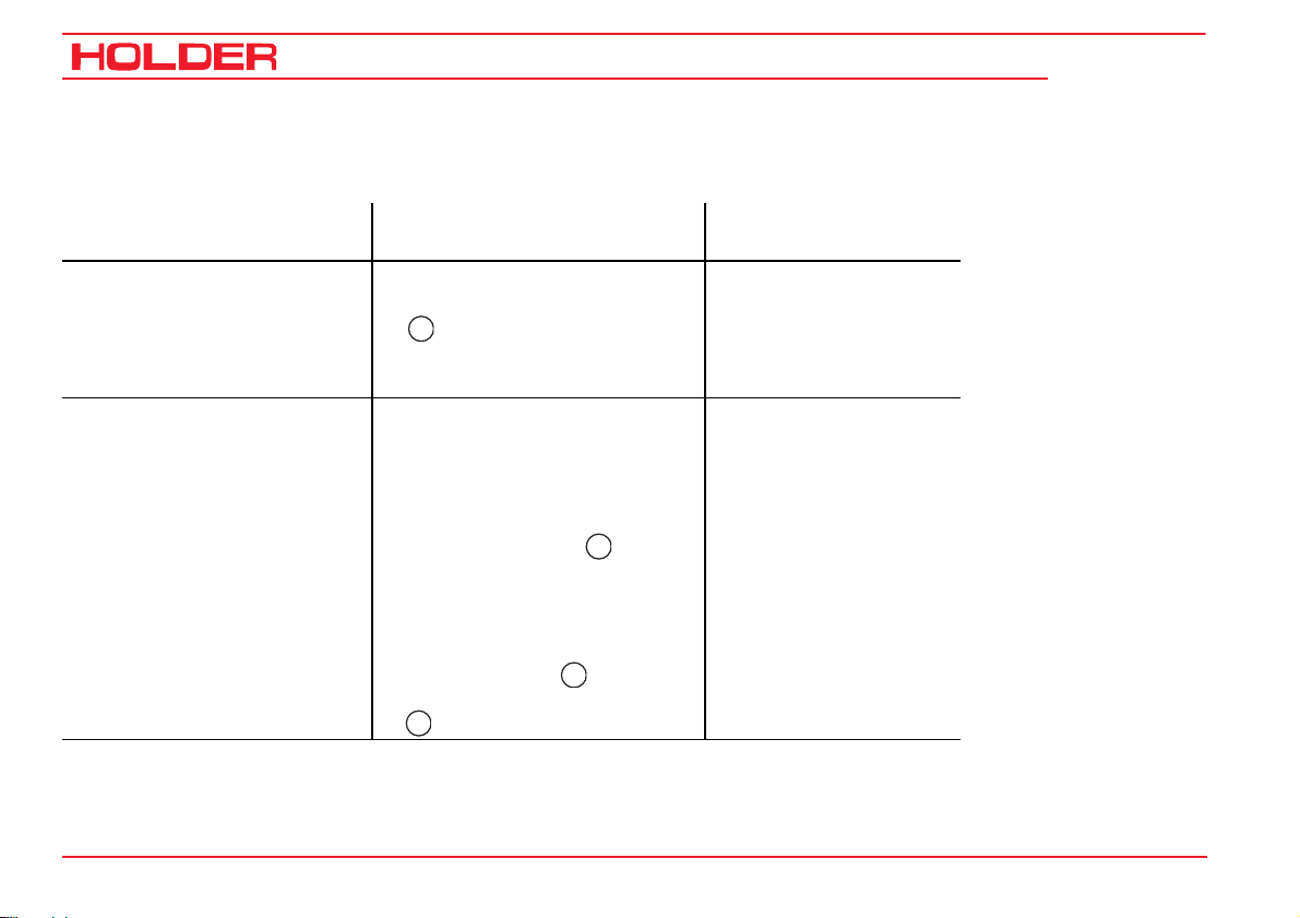
Driver’s licence classes
Tractors for farming and forestry (also with attachments)
Top speed
(design-dependent)
Up to 32 km/h
Over 32 km/h
153 146 7
Maximum total weight Driver's licence class
(minimum requirement)
No limitation B, L, T 1, 1a, 1b, 2, 3, 4, 5
Up to 3.5 t B
T: up to 60 km/h,
under 18 years only
up to 40 km/h
Over 3.5 t
to 7.5 t
C1
T: up to 60 km/h,
under 18 years only
up to 40 km/h
Previous driver's
licence class
2, 3
2, 3
Page 10
Operating Instructions
Operating instructions
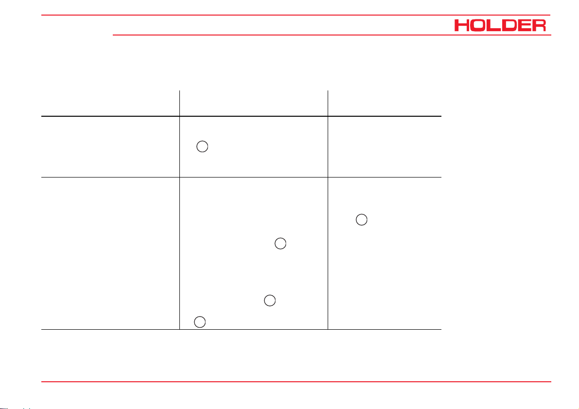
Single-axle trailers or two-axle trailers with axle base of up to 1 metre maximum
C 9.92
Maximum total weight
Trailer weight up to 750 kg B, C1, C, T 1, 1a, 1b, 2, 3, 4, 5
Trailer weight over 750 kg BE, C1E, CE, T 1, 1a, 1b, 2, 3, 4, 5
Driver's licence class
(minimum requirement)
25
L: only with additional sign
and type-dependent maximum
tractor ground speed of 25 km/h
B, C1, C: only up to 3.5 t of max.
total combined weight and max.
total trailer weight ≤ curb weight
of tractor; otherwise:
C1E: only up to 12 t max. total
combined weight and max. total
trailer weight ≤ curb weight of
tractor; otherwise:
25
L:
25
25
Previous driver's
licence class
8 153 146
Page 11
Operating Instructions
C 9.92
Multiple-axle trailers and two-axle trailers with an axle base over 1 metre
Operating instructions
Maximum total weight
Trailer weight up to 750 kg B, C1, C, T 2, 3
Trailer weight over 750 kg BE, C1E, CE, T 2, 3
Up to 3.5 t max. total weight B, C1, C: only up to 3.5 t of max.
Up to 12 t max. total weight C1E: only up to 12 t max. total
Driver's licence class
(minimum requirement)
25
L: only with additional sign
and type-dependent maximum
tractor ground speed of 25 km/h
total combined weight and max.
total trailer weight ≤ curb weight
of tractor; otherwise:
combined weight and max. total
trailer weight ≤ curb weight of
tractor; otherwise:
25
L:
25
25
Previous driver's
licence class
1, 1a, 1b, 4, 5:
each
25
153 146 9
Page 12
Operating Instructions
Operating instructions
Two trailers behind tractors for farming and forestry
C 9.92
Maximum total weight
Up to 3.5 t max. total weight B, C1, C:
Up to 12 t max. total weight C1E:
10 153 146
Driver's licence class
(minimum requirement)
BE, C1E, CE, T 2, 3
only up to 3.5 t of max. total
weight of the combination
and max. total weight of the
trailer ≤ curb weight of
tractor; otherwise:
only up to 12 t max. total
weight of the combination
and max. total weight of the
trailer ≤ curb weight of
tractor; otherwise:
25
L:
25
25
Previous driver's licence
class
1, 1a, 1b, 4, 5,
25
Page 13

C 9.92
Safety
Operating Instructions
Operating instructions
General notes on safety
• Observe your national regulations for safety and
health protection.
• Do not allow children under 16 to use the tractor.
• When using the public highway, respect the highway
code.
• Do not allow anyone to stand around where they might
get hurt.
• Do not run the engine in enclosed spaces.
• Exercise extreme caution when handling fuels. There
is a high risk of fire.
• Exercise extreme caution when handling fuel, fluids
and lubricants. These can be poisonous and corrosive.
• To prevent the danger of fire, keep the tractor and
attachments clean.
• Observe the warning notices and symbols on your
tractor.
• Emergency stop When the inching pedal or traction
hydraulics is defective, the tractor can only be
brought to a halt by setting the ignition to 0 and using
the service brake.
Working clothes
• Only wear snugly fitting clothing when working with
the tractor.
• If necessary, wear suitable headwear to keep loose
hairs and pigtails from being caught in rotating parts.
• Do not wear jewellery and similar objects, eg rings,
when working with the tractor.
Safety notes for retrofits
The tractor has electronic components whose proper functioning can be influenced by electromagnetic emissions from
other equipment. These influences can endanger persons if
the following notes on safety are not observed.
• Have the equipment installed by your service centre
only.
• Before the installation of electric or electronic equipment connected to the tractor’s electrical system,
check if these installations can interfere with the
tractor’s electronic system or other system components.
153 146 11
Page 14

Operating Instructions
Operating instructions
• The installed equipment must conform to the applicable EMC directive 89/336/EU and carry the CE
symbol.
• If you must install a mobile communications system
(or have it installed) (eg radio, mobile telephone), the
following requirements must be met:
- Only approved equipment (eg with type approval) may
be installed.
- The equipment must be installed permanently,
- The operation of portable or mobile equipment inside
the tractor is only allowed if connected to a permanently installed external antenna,
- The transmitting section must be installed away from
the tractor’s electronic system.
- When installing the antenna, install it properly and
with a good connection to tractor ground.
- Do not exceed the maximum permissible current
rating of the wiring according to the installation instructions of the equipment manufacturer.
- Before doing electric welding, disconnect all plugs
from the electronics.
C 9.92
Safety instructions for handling fuel, fluids
and lubricants
Gear oil, engine oil, diesel fuel
Do not eat, drink or smoke when handling
these fuel, fluids and lubricants. Prolonged
intensive contact may cause degreasing and
irritation of the skin. Wash the skin with water
and soap; use a skin care cream. If necessary, wear personal protective gear. Change
soaked clothes and shoes immediately. If
vapour or mist was inhaled, breathe fresh air.
Consult a doctor if the complaint persists.
After contact with the eyes, rinse the eyes
thoroughly with water (at least 10 minutes),
then consult an eye doctor. If swallowed, do
not force to vomit, but consult a doctor. Danger of slipping on the spilled product, particularly in connection with water.
Oils can contaminate water. Always keep them
in approved containers. Avoid spilling fluids.
Remove spilled fluids immediately with an oil
binding agent and discard in accordance with
laws and regulations. Discard old fluids as specified.
12 153 146
Page 15
C 9.92
Observe applicable laws and regulations. Oils
are inflammable. Do not let them come in
contact with hot engine parts as fire can result.
Hydraulic oil, brake fluid
During tractor operation, these fluids are pressurized and pose a health hazard. Do not spill
these fluids. Remove any spilled fluids immediately with an oil binding agent and discard
them as specified. Discard the old fluid as specified. Observe applicable laws and regulations.
Do not allow them to come in contact with hot
engine parts. Danger of fire!
Avoid contact with the skin. Avoid the inhalation of spray fog. The penetration of pressurized fluids into the skin is particularly dangerous if these fluids are under high pressure and
escape from the hydraulic system through
leaks. Seek medical aid at once in case of such
injuries.
If injuries can not be excluded, use a suitable
personal protector (for example, protective
gloves, glasses and skin protection and skin
care creams).
Operating Instructions
Operating instructions
Battery acid
Battery acid contains dissolved sulphuric
acid. This acid is poisonous and caustic. When
working with battery acid, always wear protective clothing and eye protectors. Do not
allow acid to contact the clothing, skin or eyes;
in case of contact wash immediately with
ample clean water. In case of personal injuries, consult a doctor at once. Neutralize
spilled battery acid immediately.
Discard old fluids as specified. Observe applicable laws and regulations.
Emissions
Exhaust Gases
During operation, the engine emits exhaust
gas into the environment. The exhaust gas
mainly consists of water vapour, carbon dioxide (CO2), carbon monoxide (CO), carbon
hydride (CH), nitrogen oxide (NOX) and soot.
The components CO, CH and NOX are poisonous or hazardous to health and should
not be inhaled in high concentrations. Soot is
a carcinogenic material.
153 146 13
Page 16

Operating Instructions
Operating instructions
Particularly the particulates contained in the
exhaust gas can cause cancer. For this reason the engine should not be operated in enclosed spaces.
Heat
The exhaust gases are very hot and can ignite inflammable material. Therefore keep the
exhaust pipe away from inflammable materials.
Battery
During charging the battery emits a mix of
oxygen and hydrogen (detonating gas). This
gas mix is explosive and must not be ignited.
The danger of explosion can be avoided with
suitable ventilation and the keeping naked
fires away. Observe the safety rules when
handling the battery.
C 9.92
14 153 146
Page 17
C 9.92
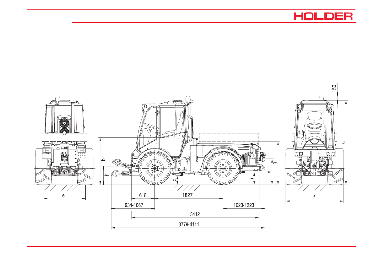
Technical data
Tractor dimensions
Dimensional drawing
Operating Instructions
153 146 15
Page 18

Operating Instructions
C 9.92
Technical data
Table of dimensions for S 990
Tow coupling
Tires Type Profile Total
height
mm
280/80 R18
280/80 R18 S
36x13.50-15 524-31-8 Multi Trac 2236 1258 220 565 965 1129 474 320
10.5-18 MPT
10.5-18 MPT S
425/55 R17 532-31-02 AC 70G 2227 1249 211 556 956 1120 465 311
425/55 R17 532-31-01 All – Ground 2221 1243 205 550 950 1114 459 305
400/60-15.5 524-31-5 404 2212 1234 196 541 941 1105 450 296
33x12.50-R15 524-31-7 Discoverer LT 2209 1231 193 538 938 1102 447 293
33/18LL-16.1 524-31-9 Turf Special 2209 1231 193 538 938 1102 447 293
532-31-08
532-31-09
524-31-1
524-31-6
XMCL 2243 1265 227 572 972 1136 481 327
AT 603 2233 1255 217 562 962 1126 471 317
Avg.
seat
height
a
mm
b
Ground
clearance
c
mm
Lowest
position
d
mm
Highest
position
d
mm
Dump
body
height
PTO height
g
mmhmmimm
33x12.50-15 524-31-4 413 TL 2194 1216 178 523 923 1087 432 278
33x15.50-15 524-31-3 412 TL 2193 1215 177 522 922 1086 431 277
31x15.50-15 524-31-2 Xtra Trac 2181 1203 165 510 910 1074 419 265
16 153 146
Page 19

C 9.92
Distance between centreline of tires
Operating Instructions
Technical data
Small turning
radius
to DIN 7020
Tires
10.5-18 MPT S 7.12 m 960 1124 1234 1398 1050 1214 1324 1488 1120 1284 1394 1558
33x12.50-15 7.19 m 1000 1084 1310 1394 1090 1174 1400 1484 1160 1244 1470 1554
10.5-18 MPT 7.19 m 1034 1052 1308 1326 1124 1142 1398 1416 1194 1212 1468 1486
280/80 R18 7.21 m 1034 1052 1324 1342 1124 1142 1414 1432 1194 1212 1484 1502
33x12.50R15 7.30 m - 1084 - 1427 1090 1174 1433 1517 1160 1244 1503 1587
36x13.50-15 7.35 m - 1084 - 1465 1090 1174 1471 1555 1160 1244 1541 1625
400/60-15.5 7.38 m - 1104 - 1504 - 1194 - 1594 1142 1264 1542 1664
425/55 R17 7.42 m - 1114 - 1545 - 1204 - 1635 - 1274 - 1705
280/80 R18 S 7.30 m - 1124 - 1414 1050 1214 1340 1504 1120 1284 1410 1574
31x15.50-15 7.39 m - 1124 - 1518 - 1214 - 1608 1122 1284 1516 1678
33x15.50-15 7.39 m - 1124 - 1519 - 1214 - 1609 1122 1284 1517 1679
33/18LL-16.1 7.51 m - 1164 - 1639 - 1254 - 1729 - - - -
at min. track
width
(measured at
outermost point
of truck)
Normal track width
(flange size 1034)
Track width e Overall width f Track width e Overall width f Track width e Overall width f
Min.-mmMax.-mmMin.-mmMax.-mmMin.-mmMax.-mmMin.-mmMax.-mmMin.-mmMax.-mmMin.-mmMax.-
Type 5234-80 = 45 mm Type 526-34-70 = 80 mm
With hub spacers
mm
153 146 17
Page 20

Technical data
Weights
Operating Instructions
C 9.92
Max. curb weight
Max. front axle load
Max. rear axle load
Max. tongue weight on tow coupling
* With 33X12.50 R15 tires
Tires
Curb weight
S 990
(with driver
75 kg)
Total: kg
Front kg
Rear kg
33x12,50-15
2638 2648 2668 2696 2718 2734 2766 2790
1220 1225 1235 1249 1260 1268 1284 1296
1418 1423 1433 1447 1458 1466 1482 1494
33x12,50R15
Weight in kg
4500 kg
*2660 kg - 2700 kg
*2660 kg - 2700 kg
800 kg
31x15,50-15
33x15.50-15
10,5-18MPT
36x13.50-15
Auxiliary assemblies Total Front Rear
Inching speed
Rear lift
Dump body
400/60-15.5 33/18LL-16.1 280/80 R18 425/55 R17
13 kg 10 kg 3 kg
77 kg -25 kg 102 kg
75 kg 0 kg 75 kg
18 153 146
Page 21

Operating Instructions
C 9.92
Technical data
Tires
The pressure can deviate, depending upon the make and use of the tires. Observe the instructions of the tire
manufacturer.
Type of tyre Capacity Profile Tube Inflation pressure (in bar) Wheel ballast weights
Curb weight Max. loading Type Weight
Front Rear
280/80 R18 132A8 XMCL No 1.6 2.5 2.5 524-34-1 ca. 45 kg
36x13.50-15 114B / 4PR Multi Trac No 1.0 1.2 1.4 524-34-1 ca. 45 kg
10.5-18 MPT 10 AT 603 Yes 2.2 2.2 2.2 524-34-1 ca. 45 kg
425/55 R17 134G AC 70G No 0.8 1.6 1.6 524-34-1 ca. 45 kg
425/55 R17 134G All - Ground No 0.8 1.6 1.6 524-34-1 ca. 45 kg
400/60-15.5 132A8 404 Yes 1.8 1.8 2.0 524-34-1 ca. 45 kg
33x12.50-15 6PR 413 TL No 1.4 1.9 2.0 524-34-1 ca. 45 kg
33x12.50 R15 108Q Discoverer LT No 1.6 2.5 2.5 524-34-1 ca. 45 kg
33x15.50-15 6PR 412 TL No 1.0 1.6 1.6 524-34-1 ca. 45 kg
33/18LL-16.1 10PR Turf Special No 1.2 1.8 2.0 - -
31x15.50-15 115B Xtra Trac No 2.0 3.2 3.2 524-34-1 ca. 45 kg
Note: Observe the max. tire inflation pressure (max. loading) for the max. axle load and for road travel.
Adjust the inflation pressure acc. to the data of the tire manufacturer for max. tractive force for off road travel and
to reduce the ground pressure.
153 146 19
Page 22

Operating Instructions
Technical data
Engine specifications
S 990
Manufacturer Deutz AG
Model designation TD2011 L04w
Engine type 4-stroke diesel
No. of cylinders 4
Cubic capacity 3619 cm³
Specific fuel consumption 216 g/kWh
Rated speed 2600 rpm
Upper idle speed 2600 rpm +200 rpm
Lower idle speed 900-950 rpm
Power to 97/68 EC
n=2600 rpm
68.0 kW (92 HP
C 9.92
)
20 153 146
Page 23

C 9.92
Theoretical ground speeds
Operating Instructions
Technical data
Transmission
Engine output 68 kW
Engine speed 2600 RPM
Tires Type Unit
280/80 R18 532-31-08/09 km/h 31.3 32.3 39.1
36x13.50-15 524-31-8 km/h 31.1 32.1 38.8
10.5-18MPT 524-31-1/-6 km/h 30.8 31.7 38.4
425/55 R17 532-31-01/-02 km/h 29.8 30.7 37.2
400/60-15.5 524-31-5 km/h 29.7 30.7 37.1
33x12.50-15 524-31-4 km/h 29.4 30.3 36.7
33x12.50R15 524-31-7 km/h 29.2 30.1 36.4
33x15.50-15 524-31-3 km/h 28.8 29.7 35.9
33/18LL-16.1 524-31-9 km/h 28.8 29.7 35.9
31x15.50-15 524-31-2 km/h 26.5 27.3 33.0
Hydrostatic
drive
Dual Drive
30 km/h
Dual Drive
40 km/h
153 146 21
Page 24

Operating Instructions
Technical data
Technical data /filling quantities
C 9.92
Assembly
Hydrostatic drive
PTO shafts 2 PTOs (front and rear), sense of rotation: clockwise when looking
- RPM at front 540 RPM at 2200 engine RPM, 1000 RPM at 2390 engine RPM
- RPM at rear 1000 RPM at 2360 engine RPM
- Spline profile 1 3/8’’ (6) DIN 9611
PTO clutch Wet multi-disc clutch, electro-hydraulically operated
Differential lock Simultaneous front and rear operation, electro-hydraulically operated
Fuel system
Fuel tank Diesel fuel 82 litres
Additional
information
Description
Infinitely variable ground speed, 2 mechanical speed ranges
on shaft end
22 153 146
Page 25

C 9.92
Operating Instructions
Technical data
Assembly
Steering
- Type Hydrostatic with 2 double-acting steer cylinders
- Steering valve Orbitrol OSPC 125 LS (single-stage) or OSPD 125/205 (two-stage)
Brakes
- Service brake Multi-disc brake, wet, acting on all 4 wheels
- Actuator Hydraulic
- Parking brake Multi-disc brake, wet, acting on all 4 wheels
- Operation Electrically-operated
Tow coupling
- Type Cramer, height-adjustable
Front lift
- Type 3-point, upper link adjustable
- Attachment Category I and II
- Lifting power 2700 N (measured at attachment points)
- Cylinder 2 cylinders, double-acting
Additional
information
Description
153 146 23
Page 26

Operating Instructions
C 9.92
Technical data
Assembly Additional information Description
Rear lift
- Type HOLDER standard 3-point
- Attachment Category I and II
- Lifting power 15700 N (measured at attachment points)
- Cylinder 2 cylinders, double-acting
Dump body
- Dimensions L X W X H 1530 x 1140 x 215 mm
- Load capacity 1300 kg
Traction hydraulics
Variable pump Hydromatik
- Type A4 VG 40 EP
- Output 160 litres/min
- Operating pressure 380 bar (430 bar maximum)
Variable motor Hydromatik
- Type A6 VM 55 EP
- Displacement 26.1 - 55 cm3/rev
Hydraulic oil tank 45 L (common oil tank for traction and working hydraulics)
24 153 146
Page 27

C 9.92
Operating Instructions
Technical data
Assembly
Working hydraulics (with
steering)
Pump Sauer-Sundstrand
- Type -
- Output 17 cm3/rev (42.5 L/min at 2500 engine RPM)
- Operating pressure 180-190 bar
Hydraulic oil tank 45 L (common oil tank for traction and working
Electrical system
- Operating voltage 12 VDC
- Battery 12 V / 100 Ah
- Alternator 12 V / 95 A
- Starter motor 12 V / 2.4 kW
General tractor
- Operating range - 30°C to + 50°C
Additional
information
Description
hydraulics)
153 146 25
Page 28

Operating Instructions
Technical data
Noise level
The tractor emits the following noise level (measured at the
driver’s ear) according to EU Standard 77/311/EEC; measurement according to Appendix II.
Table of noise levels and absorption rating
C 9.92
Model
S 990 TD2011 L04w 68.0 kW (92 HP) 85 85 84 84 1.3
*Roof hatch and side window open
Type of
engine
Engine output Noise level dB(A) Absorption value
Cabin open* Cabin closed
Left Right Left Right
Exhaust gas identification
The absorption rating is stated on the type plate.
26 153 146
Page 29
C 9.92
Operating Instructions
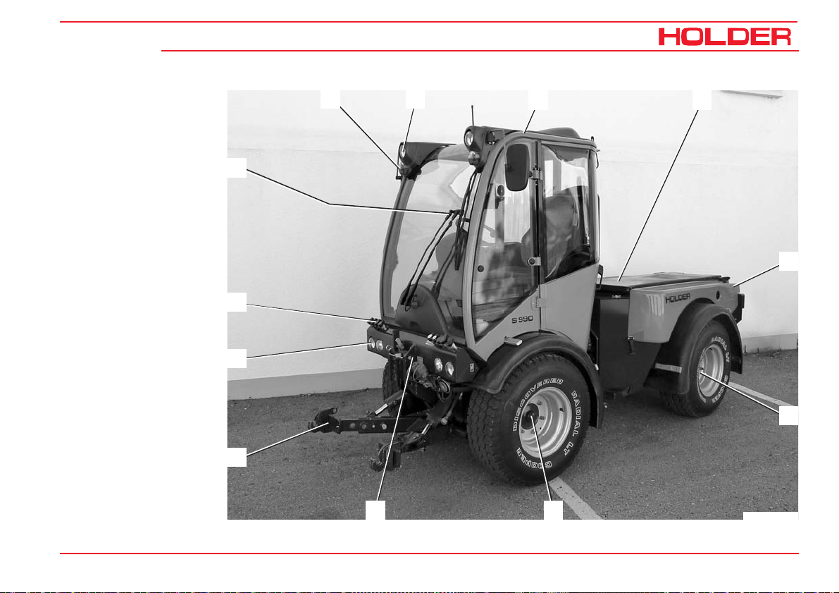
Description
Views of vehicle
Front left view
1 Turn signal and
position light
2 Top headlight
3 Driver’s cab
4 Dumping subframe
(dumping device)
5 Rear end of tractor
6 Rear axle
7 Front axle
8 Upper link bracket
9 Lower link frame
of front lift
10 Headlight
11 Plug-in hydraulic
quick couplings for
attachments*
12 Wiper/washer
12
11
10
9
1
2
3
4
5
6
8
153 146 27
7
Bild_S 990_010
Page 30
Description
Tractor
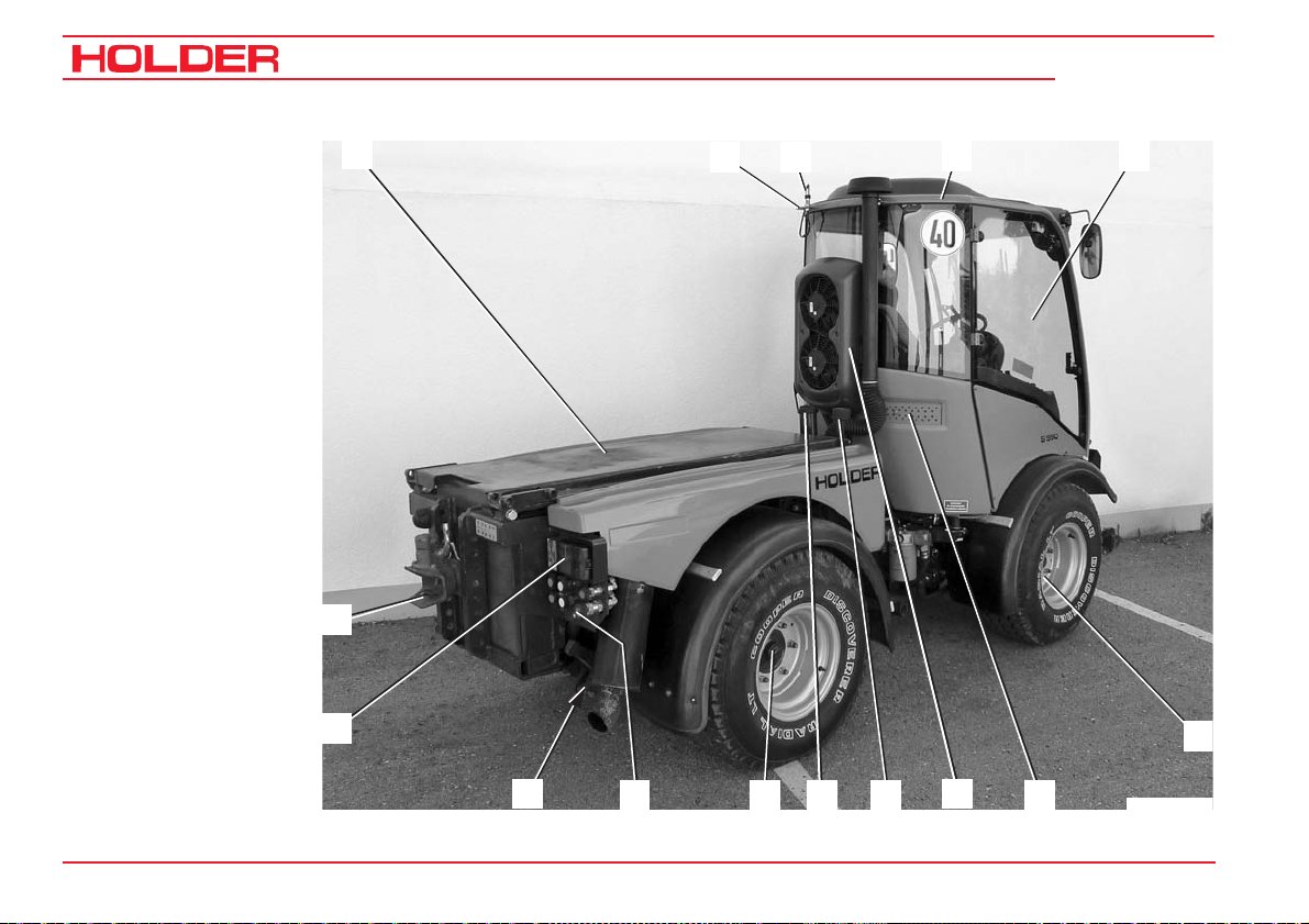
Rear right view
1 Dumping subframe
2 Working light*
3 Mount for
top strobe warning
light*
4 Driver’s cab
5 Front end of tractor
6 Front axle
7 Intake screen of
fresh air fan
8 Engine air intake
9 Hydraulic oil filler
neck
10 Fuel filler neck
11 Rear axle
12 Plug-in hydraulic
quick couplings for
attachment*
13 Lower link frame
of rear lift*
14 Tail light, left/right
15 Trailer coupling
* Option
Operating Instructions
1
15
14
13
12
C 9.92
4
8
7
11
3
10
9
2
5
6
Bild_S 990_011
28 153 146
Page 31

C 9.92
Driver’s station
Operating Instructions
3
Description
4
Operating controls
1 Direction lever
2 Lever for left side window
3 Steering wheel
4 Multifunctional display
5 Lever for right side window
6 Turn signal and wiper lever
7 Toggle switch for meter
(ground speed in km/h or PTO RPM)
8 Ignition lock
9 Toggle switch for top headlight
10 Light switch
11 Accelerator pedal
12 Brake pedal
13 Preheating indicator
14 Speed range selector
15 Inching pedal
16 Parking brake switch
17 Switch for two-stage steering*
18 Toggle switch for console or steering column direc-
tion switch
* Option
2
1
18
17
16
15
14
13
5
6
7
8
9
10
1112
Bild_S 990_001
153 146 29
Page 32

Operating Instructions
Description
Controls on right front console
1 Pressure gauge for hydraulic accumulator*
2 Master switch for working hydraulics
3 Fine adjustment knob for attachment variable pump*
4 Switch for attachment variable pump*
5 Front PTO* switch
6 Forward/reverse switch
7 Driving program switch
8 Fine adjustment knob for ground speed (in ground
speed ranges 3 and 4)
9 Joystick for working hydraulics
10 Float positions for 3 plug-in quick couplings
11 Membrane keyboard for front lift
12 Membrane keyboard for tilt control
13 Membrane keyboard for lateral control*
14 Membrane keyboard for 2nd circuit priority flow
valve*
15 Membrane keyboard for 1st circuit priority flow valve*
15
14
C 9.92
2 31
4
1213
5
91011
6
7
8
Bild_S 990_005
* Option
30 153 146
Page 33

C 9.92
Controls on right rear console
1 Fine adjustment knob for ground speed (in ground
speed ranges 3 and 4)
2 Driving program selector switch
3 Differential lock toggle switch
4 Fan toggle switch
5 Hydraulic oil level warning light
6 Hydraulic oil temperature gauge
7 Fan reversing toggle switch*
8 Air conditioning toggle switch*
9 Throttle control knob
10 Power socket
11 Heater control
12 Air conditioning control*
13 Working light switch*
14 Top strobe warning light switch
15 Hazard warning flasher switch
Operating Instructions
321
15 1314 1112
Description
64 5 7 8 9
10
Bild_C992H_005
* Option
153 146 31
Page 34

Operating Instructions
Description
Controls on rear console
15 Diagnostic socket for working hydraulics
16 Diagnostic socket for traction hydraulics
17 Traction electronics trouble diode
15
C 9.92
1716
Bild_S 990_012
Hand throttle
1 Outer ring for fine control:
- Turn clockwise for RPM reduction
- Turn counter-clockwise for RPM increase
2 Inner knob for coarse control
- Pull up for RPM increase
- Push down for RPM reduction
- Push down fast for emergency reset to idle speed
32 153 146
1 2
Bild_C992H_006
Page 35

C 9.92
Joystick
1 Pushbutton 1 for joystick level 1
2 Pushbutton 2 for joystick level 2
3 Pushbutton 3 for joystick level 3
4 Joystick (with no button pressed = joystick level 0)
Operating Instructions
3
2
1
Description
4
Bild_C992H_007
Pedals
1 Inching pedal
2 Brake pedal
3 Accelerator pedal
153 146 33
1
2 3
Bild_C992H_008
Page 36

Operating Instructions
Description
Steering column adjustment
1 Brake fluid reservoir
2 Steering column adjustment lever
C 9.92
1
2
34 153 146
Bild_C992H_009
Page 37

C 9.92
Multifunctional display, legend
Operating Instructions
Description
15 16 1 2 3
1 Fuel gauge
2 Engine oil temperature
gauge
3 Tachometer with marks
for PTO RPM
4 Hour meter
5 Digital speedometer
Indicator lights:
6 Turn signal indicator
7 Turn signal indicator for
2nd trailer
8 Turn signal indicator for
1st trailer
9 High beam
10 Low beam
11 Engine oil temperature
12 Preheating
13 Engine oil pressure
14 Battery
15 Parking brake
16 Differential lock
14
13
12
11
15
Motor
1
2
6
Km/h
digital system
5
10
RPMx100
5
0
electronic
0000000 h
478910
20
25
30
Bild_C992H_071
153 146 35
Page 38

Operating Instructions
Description
Controls at front top of cabin
1 Dome light
2 Loudspeaker
C 9.92
1 2
Bild_C149
Controls at front bottom of cabin
1 Wiper fluid reservoir
2 Radio
36 153 146
1
2
Bild_C282
Page 39

C 9.92
Controls at rear of cabin
1 Roof hatch handle
2 Roof hatch
Operating Instructions
Description
1
2
Bild_C263
Door controls
1 Door opener
153 146 37
1
Bild_C156
Page 40

Operating Instructions
Description
Location of plates and
labels
Identification plates
1 Engine type plate
2 Variable motor type plate
3 Variable pump type plate
4 Cabin type plate
5 Chassis serial number
(on front support on right side)
6 Machine type plate
(on front support)
C 9.92
38 153 146
Page 41

C 9.92
Mounting instructions for licence plate
- Install the front licence plate (1) on the cover below
the windshield wipers.
Remove the cover before installing the licence plate.
- Install the rear licence plate (2) at the rear below the
left tail light.
Operating Instructions
Description
1
Bild_C992H_010
2
153 146 39
Page 42

Operating Instructions
Description
Overview of options and variants (selection)
Assembly Additional information Dimension/order
no./type
Activated carbon filter for cabin ventilation 131667
Heating element for oil preheating (engine) From –20°C (230VAC) 5234-69
Air conditioning 534-34-80
Seat heater 204-34-83
Lap seat belt 204-34-81
Comfort backrest extension 204-34-80
Left armrest 204-34-82
Rear working light 204-34-88
Hydraulic lateral control For front lift 204-01-01
Rear lift 534-51-04
Mounting For ball-type hitch 526-51-73
C 9.92
Ball-type hitch 526-51-74
Top strobe warning light 526-34-74
40 153 146
Page 43

Operating Instructions
C 9.92
Description
Assembly Additional information Dimension/order
no./type
Electro-hydraulic accumulator 204-80-19
Circuit 1 priority flow valve 204-80-04
- Hydraulic pump Series pump
- Output 17 cm³/rev
- Flow rate 0-25 litres/min
- Maximum pressure 200 bar
Circuit 2 priority flow valve 534-80-25
- Hydraulic pump Tandem pump
- Output 14 cm³/rev
- Flow rate 0-25 litres/min
- Maximum pressure 200 bar
153 146 41
Page 44

Operating Instructions
Description
Assembly Additional information Dimension/order
no./type
Attachment variable pump 0-120 litres/min adjustable 534-80-30
- Hydraulic pump A11VO40EP
- Output 0-40 cm³/rev
- Flow rate 0-120 litres/min
- Maximum pressure 280 bar
Attachment encoding wiring harness For attachment variable pump 204-80-72
Power hydraulic system 80 litres/min fixed 534-80-35
- Hydraulic pump Mounted on traction pump Gear pump
- Output 22 cm³/rev
- Flow rate 80 litres/min
- Maximum pressure 210 bar
C 9.92
42 153 146
Page 45

Operating Instructions
C 9.92
Accessories
The tractor is delivered with the following accessories:
Operating instructions
Folder
2 ignition keys
2 door keys
2 tank cap keys
2 reducer sleeves for Category I attachments
Upper link with retaining pins
Key folder
Bio pass for proof of filling environment-friendly hydraulic
oil
Description
153 146 43
Page 46

Page 47

Operating Instructions
C 9.92
Taking into service
Daily checks and activities prior to taking
into service
If damages or defects are found during the following checks,
they must be eliminated before taking the tractor into service. Do not operate the tractor before proper repairs are carried out. Safety and protective devices should not be removed or disabled. Do not change fixed specified settings.
Before starting work, make yourself truck familiar with all
the functions and protective devices of the tractor.
Checking/cleaning the radiator and protection screens
NOTE
- Check that the protection screens (2 and
3) are clean.
- Clean the screens if necessary.
The screen (3) can be pulled off to the left
after loosening the bayonet screw (4) and
then easily cleaned.
- The air intake of the air filter (1) must be
clean.
1
2
3
Bild_C992H_011
3
4
153 146 45
Bild_S 990_006
Page 48

Operating Instructions
Taking into service
Turning on the battery isolating switch
NOTE
The battery can be switched off fully with the
removable key.
- Insert the key (1) into the battery isolating switch and
set it to the horizontal position.
The battery circuit is turned on.
Checking the engine oil level
NOTE
Check the engine oil level only when the vehicle is parked on level ground.
- Let the engine run for approx. 2 minutes.
- Stop the engine and pull out the oil dipstick (1) after
approx. 1 minute.
- The oil level must be between the Min and Max marks.
- Top up oil as specified in the maintenance instructions.
ATTENTION
Do not fill too much oil.
C 9.92
1
Bild_C992H_014
1
46 153 146
Bild_C992H_015
Page 49

Operating Instructions
C 9.92
Checking the trailer coupling (optional) if necessary
- Check the trailer coupling for proper condition and
operation. Carry out the check according to the
instructions in the section „Operating the trailer
coupling“.
Checking the tire inflation pressure
NOTE
Your tractor can be equipped with different
types of tyres. The specified inflation pressure for your tires is given in the table entitled „Tires“ in the technical data section.
- Check the inflation pressure an all four tires. All tires must
have the same pressure. Low pressure will increase the
rolling resistance. This will cause increased fuel consumption and tire wear, and the driving characteristics will
become poorer.
DANGER
If the inflation pressure is too high, the tires
can explode!
Taking into service
Bild_S 990_015
- The tires should not be damaged or worn.
- Have damaged tires replaced without delay. Due to the
longer braking distance, the risk of an accident will be
higher.
153 146 47
Bild_S 990_014
Page 50

Operating Instructions
Taking into service
Checking the hydraulic oil level
- Retract all hydraulic cylinders.
- Check the oil level at the sight glass (2).
- The oil level must be at the centre (1) of the sight
glass.
- Top up oil through the filler neck (3) as specified in
the maintenance manual.
C 9.92
1
2
3
Bild_S 990_016
48 153 146
Page 51

C 9.92
Filling fuel
- If necessary, read the fuel level (1) on the multifunc-
tional display.
CAUTION
Danger of fire when handling fuels. Stop the
engine. Do not fill fuel in the vicinity of naked
flames, ignition sparks or hot engine parts.
Do not smoke when refuelling.
- Remove the fuel tank filler cap (2).
- Top up diesel fuel as recommended in the mainte-
nance instructions.
Operating Instructions
Taking into service
1
Motor
1
2
Km/h
digital system
15
10
5
0
0000000 h
RPMx100
electronic
20
25
30
Bild_C992H_073
Filling quantity ............................................. approx. 82 L
2
- Refit the filler cap (2).
Bild_C992H_016
153 146 49
Page 52

Operating Instructions
Taking into service
Checking the brake fluid level
- Check the level at the brake fluid reservoir (1).
- The brake fluid level fluid level must between the Min
and Max marks on the reservoir.
- Top up brake fluid as specified in the maintenance
instructions.
Adjusting the steering wheel
NOTE
The inclination and height of the steering
wheel can be set to a comfortable position.
DANGER
Do not adjust the steering wheel while driving.
- Loosen the lever (2).
- Adjust the tilt and height of the steering wheel (3).
- Retighten the lever (2).
C 9.92
1 2
Bild_C992H_017
3
2
50 153 146
Bild_C992H_018
Page 53

C 9.92
Adjusting the driver’s seat with pneumatic suspension
1 Backrest
2 Lumbar support adjustment knob
3 Backrest tilt
4 Weight adjustment
5 Horizontal suspension
6 Horizontal adjustment
DANGER
Do not adjust the seat while driving. Risk of
accident!
Operating Instructions
Taking into service
1
2
- Adjust the seat so that all the controls can be
reached and operated safely.
NOTE
If separate operating instructions for the seat are
supplied with your tractor, follow these instructions.
Adjusting the lumbar support
- Be seated and lean against the backrest (1).
- Turn the lumbar support adjustment knob (2) until the
most comfortable position is reached.
153 146 51
Bild_010
Adjusting the backrest tilt
- Pull the tilt lever (3) up.
- Use the back to adjust the backrest tilt.
- Release the tilt lever.
456
3
Page 54

Operating Instructions
Taking into service
Adjusting the driver’s weight
- Be seated.
- Pull the weight adjustment grip (4) up.
NOTE
A noise can be heard. The seat will adjust
automatically to the weight of the driver. The
noise stops.
- Release the lever.
Adjusting the horizontal suspension
- Pull the horizontal suspension lever (5) back:
Seat suspension in horizontal direction is released.
- Move the horizontal suspension lever (5) forward.
Seat suspension in the horizontal direction is locked.
Horizontal seat adjustment
- Pull the horizontal seat adjustment lever (6) up.
- Slide the seat horizontally forward or back to the
suitable seating position.
- Release the horizontal seat adjustment lever.
Bild_010
C 9.92
1
456
2
3
52 153 146
Page 55

Operating Instructions
C 9.92
Topping up wiper water
NOTE
The washer water reservoir for the windshield
washer system is located at the front left in
the footwell of the cabin.
- Open the filler cap (1) and top up washing water in the
reservoir (2).
Taking into service
1
2
Filling capacity .......................................... approx. 1.3 L
Checking the lights and rear view mirror
- Check the lights for proper operation. Carry out the
check according to the instructions in the section
entitled „Lights“.
- Adjust the rear view mirror so that the roadway behind
the tractor and the working area can be seen well.
153 146 53
Bild_S 990_017
Bild_S 990_014
Page 56

Operating Instructions
Taking into service
C 9.92
Starting the engine
Engine instructions before operation
DANGER
Do not start or run the engine in enclosed
spaces. Danger of poisoning through exhaust
gases!
Starting instructions
CAUTION
Before starting, make sure no-one is in the
vicinity of the tractor.
ATTENTION
Do not use a starting aid such as a start pilot
or similar means. Turn off the traction drive or
any driven attachments.
CAUTION
Start the engine only from the driver’s station.
54 153 146
Page 57

C 9.92
Starting the engine
- Set the direction switch (1) to the neutral position
(centre).
- Fully depress the inching pedal (2).
NOTE
The engine can only be started if the inching
pedal is fully depressed (starting safety
switch).
- Set the hand throttle (4) to idle (push in fully).
- Insert the ignition key and turn the preheat/starter
switch (3) to position 1.
Operating Instructions
Taking into service
1
2
3
Bild_C992H_021
4
Bild_C992H_022
153 146 55
Page 58

Operating Instructions
Taking into service
NOTE
The battery charging indicator (6), the engine
oil pressure indicator (7), parking brake indicator (8) (if parking brake is engaged) come
on.
- Turn the ignition key to position 2.
The engine will be preheated. The preheating indicator
(5) will come on.
NOTE
When starting at low temperatures, hold the
ignition key longer (approx. 1 minute) in position 2.
5 96
C 9.92
8 10
7
15
Motor
1
2
Km/h
digital system
10
RPMx100
5
0
electronic
0000000 h
20
25
30
Bild_C992H_074
- When the preheating indicator extinguishes, turn the
ignition key to position 3 to start the engine.
- Release the ignition key after the engine has started.
The battery charging indicator (7) and the engine oil
pressure indicator (6) should extinguish.
ATTENTION
Operate the starter only for a maximum of
20 seconds. Wait one minute, then repeat the
- Set the engine speed with the hand throttle or accelerator pedal to the desired RPM (9).
- The hour meter (10) is activated.
starting procedure. Repeat the starting procedure only twice at most. In case the engine does not start, carry out a troubleshooting according to the section entitled „Malfunctions, causes, remedy“.
56 153 146
Page 59

Operating Instructions
C 9.92
Starting the engine with automatic preheating
Starting procedure
- Turn the ignition key to position 1.
- The engine will be preheated. At temperatures below
+10°C the yellow lamp (2) and the preheating indicator
light (1) will come on.
- When the yellow lamp (2) goes out, turn the ignition
key to position 3 to start the engine.
- The automatic preheating will turn off some time after
starting and the preheating indicator light (1) will go
out.
Taking into service
1
2
Bild_C288
NOTE
If the engine is not started, the preheating
procedure will cease approx. 10 s after the
yellow lamp (2) has gone out.
153 146 57
Checking the brakes and steering for proper function
- Make a short trial run and check the steering and
brakes for proper operation.
DANGER
Do not drive a vehicle with a defective steering and/or braking system.
Page 60

Page 61

C 9.92
Operation
Before starting to drive
Operating Instructions
When driving on public roads, observe the traffic regulations.
Driving safety rules
• Drive the tractor only from the driver’s station with the
cab doors closed.
• Always adjust your speed to the driving conditions
and the load carried.
• Before driving, check that no-one is standing in the
immediate vicinity of the tractor.
• The driving behaviour of the tractor is strongly affected by the weight and swing range of the attachments,
trailers and, if fitted, ballasting. Therefore drive slowly
with heavy equipment and take the longer braking
distance into consideration.
153 146 59
• When following a curve with a trailer or other attachments, do not forget to take the added length and drag
into consideration.
DANGER
Any parts of the attachments posing a traffic
hazard must be covered or identified with
warning signs before driving off.
• Switch off the differential lock when travelling in a
curve.
• When driving on slopes, always drive downhill if
possible; if you have to turn, only make a turn uphill.
• On steep slopes you can improve traction by activating the differential lock.
• Drive across slopes only in accordance with the
instructions at the end of this section.
Page 62

Operating Instructions
Operation
Driving
Driving with hydrostatic drive
- Start the engine.
- Preselect the direction of travel with the direction
switch (1).
- Pull up the direction switch (1) and move it forward or
backwards (forward or reverse).
NOTE
After the start of the engine, the direction
switch must be operated once if it was in the
forward or reverse position when starting. This
feature is to prevent accidental movement of
the vehicle when starting the engine.
NOTE
You can also reverse the direction of travel
while driving at reduced speed.
CAUTION
The tractor will brake strongly and speed up
again in the opposite direction.
C 9.92
1
Bild_C165
- Set the speed range knob (2) (at the steering column)
to the desired ground speed range:
ATTENTION
The tractor must be stationary for switching.
Bild_C992H_075
60 153 146
2
Page 63

Operating Instructions
C 9.92
Operation
Table of ground speed ranges
Position Marking Function Ground speed* Use
Lower position S Fast range 0 – 30 / 36 km/h Lower tractive force, eg for road travel
Centre position 0 Drive off Towing
Lower position L Slow range 0 – 11.5 km/h
- Select the desired driving program with the driving
program switch (2). The set position is illuminated:
You can choose between 4 programs:
Range 1 and 2 eg road travel
Range 3 and 4 eg work
applications
153 146 61
High tractive force, eg for working or
pulling trailers on gradients
2
Bild_S 990_004
Page 64

Operating Instructions
C 9.92
Operation
Table of driving programs•
Position Marking Function Use
Range 0 STOP Traction drive off
Range 1 Hare symbol Maximum ground speed eg on roads
Range 2•• Turtle symbol Maximum ground speed eg on roads
The ground speed, which can be set with the fine
Range 3 PTO symbol
Range 4 Snow blower symbol
• The driving programs can be optimized by your service centre for special applications, eg controlled constant speed.
•• SDS* Driving Comfort functions only in driving range "L".
With SDS* Driving Comfort the driving speed is controlled with the accelerator pedal.
adjustment knob, is adjusted automatically in
case of a high power demand of the attachment,
The ground speed, which can be set with the fine
adjustment knob, is adjusted automatically in
case of high power demand of the attachment,
eg when mowing.
eg especially adjusted
to the snow blower
* Option
62 153 146
Page 65

Operating Instructions
C 9.92
Selecting road travel (transport speed)
The tractor is stationary.
- Set the program switch (2) to speed range 1 or 2.
NOTE
You can also change the speed range while
driving at reduced speed.
- Release the parking brake.
- Depress the accelerator for the desired ground speed.
The tractor will start off and can be driven up to the
maximum ground speed of the selected speed range.
- You can read the engine RPM (5) and ground speed
(4) on the multifunctional display.
Setting the operating speed of programs 3 and 4
Operation
21
4
3
Bild_C992H_024
5
NOTE
With programs 3 and 4 you can set the ground
speed independently of the PTO RPM.
1
2
153 146 63
Km/h
Motor
5
digital system
15
10
0
0000000 h
RPMx100
electronic
20
25
30
Bild_C992H_076
Page 66

Operating Instructions
Operation
The tractor is stationary.
- Set the fine adjustment knob (1) to 0.
- Set the program switch (2) to speed range 3 or 4.
- Adjust the PTO RPM with the hand throttle (3).
NOTE
The engine speed must be at least 1500 RPM as
the control only begins to function at this RPM.
NOTE
You can also change the ground speed ranges
while driving.
The speed ranges 3 and 4 will set a speed controlled by the
power requirement of the PTO. This means, for example,
that when the snow blower needs more power when meeting with higher resistance, the tractor will drive more slowly.
When resistance decreases, the tractor will speed up to the
preset speed. Range 4 is especially trimmed to particular
applications.
C 9.92
21
3
Bild_C992H_024
- Release the parking brake.
- The ground speed is controlled with the fine adjustment knob (1).
64 153 146
Page 67

Operating Instructions
C 9.92
Adjusting the fine adjustment knob
NOTE
You can adjust the fine adjustment knob (1) any
time while driving for a fine and stepless control of
the ground speed.
- In position 0 the tractor is stationary. When the knob
is turned clockwise, the tractor will start off and in end
position 11 of the scale the maximum speed of the
range will be reached.
- You can read the engine RPM and ground speed on
the multifunctional display.
NOTE
In this operating mode the tractor will drive automatically and will only need to be steered.
This mode is ideal for the operation of an attachment as
you can concentrate fully on controlling the attachment.
Operation
21
3
Bild_C992H_024
153 146 65
Page 68

Operating Instructions
Operation
Driving with SDS (Special Drive System)*
For the selection of the programs 1, 3 and 4 at the program
switch (2) refer to the section on driving on pages 63 and
64.
Driving program 2 (SDS)
- Set the speed range knob (5) to range L.
ATTENTION
The tractor must be stationary for switching.
C 9.92
21
3
- Set the program switch (2) to range 2.
NOTE
In this range, the fine adjustment knob (1) is
not operational. The control is assumed by
the pedal (4).
- Set the engine RPM with the hand throttle (3).
- You can now control the ground speed steplessly with
the pedal (4) (accelerator).
Bild_C992H_024
5
* Option
66 153 146
Bild_S 990_002
4
Page 69

Operating Instructions
C 9.92
Operating the inching pedal
7 Inching pedal
8 Accelerator
This function is effective in all driving programs.
NOTE
If you must reduce speed temporarily, you
can do it with the inching pedal.
ATTENTION
If the inching pedal is floored, for example,
for an EMERGENCY STOP, the tractor will
brake strongly.
- Operate the inching pedal (7). The tractor will deceler-
ate and come to a complete stop.
- After passing the obstacle, release the inching pedal.
The tractor will drive again at the preset speed.
Changing the direction of travel
Operation
7
9
8
Bild_C992H_026
- Preselect the new direction of travel with the direction
switch (9).
- The tractor will come to a standstill and accelerate in
the new direction of travel.
Bild_C170
153 146 67
Page 70

Operating Instructions
Operation
Driving with hydrostatic DUAL drive
- Set the speed range selector (1) to „S“.
The DUAL Drive will only work in this range.
C 9.92
1
Table of ground speed ranges with DUAL Drive
Position Marking Function Hydrostatic ground
speed*
Lower position S Fast range 0 - 30 / 36 km/h 0 - 30 / 42 km/h Low tractive force,
Centre position 0 Drive off For towing
Upper position L Slow range 0 - 11.5 km/h / 14.5
km/h
* Depending on model
68 153 146
Ground speed*
with Dual Drive
– High tractive force, eg
Use
eg for road travel
for working or pulling
trailers on gradients
Bild_S 990_003
Page 71

C 9.92
- Set the program switch (2) to range 2.
ATTENTION
Drive the tractor warm for approx. 10-12 min.
at range 2.
- Set the program switch to range 1.
NOTE
The functions of the travel drive are identical
except it does not lock the differential:
When the ground speed* exceeds 25 km/h,
the transmission automatically switches from
the hydrostatic drive to the mechanical gear.
When the speed drops again, the transmission goes back to the hydrostatic drive.
Operating Instructions
Operation
2
Bild_S 990_004
* Depending on model
153 146 69
Page 72

Operating Instructions
Operation
Switching the differential lock on
NOTE
With the differential lock you can improve traction on soft, slippery ground. The lock is engaged when the engine speed is over 1000
RPM. You can engage the differential lock only
briefly by pressing the button momentarily.
ATTENTION
The differential lock may only be used when
driving straight ahead.
C 9.92
1
Bild_C992H_027
- Depress the differential lock switch (1) at the rear and
hold it.
2
The indicator (2) in the multifunctional display will light
up red. An intermittent acoustic warning signal will
sound at the same time.
The differential lock acts on both axles.
Switching the differential lock off
- Release the differential lock switch (1).
The indicator light (2) will extinguish and the acoustic
Motor
5
1
2
Km/h
digital system
15
10
0
0000000 h
RPMx100
electronic
20
25
30
warning signal in the multifunctional display cease.
Bild_C992H_077
70 153 146
Page 73

Operating Instructions
C 9.92
Steering
The tractor has an hydraulically-actuated articulated steering. The wheels also stay in track in curves so that attachments are guided without any lateral offset.
Steering
- Turn the steering wheel (1) in the desired direction.
The possible turning radii depend on the tires and track width
of your tractor. For exact information refer to the track width
table in the section „Technical data“.
Two-stage steering*
Operation
2
1
Bild_C992H_028
The tractor can be driven with two steering speeds.
- Indirect steering (travelling on roads - slow steering speed.)
- Direct steering (on the job - fast steering speed.)
- Depress the toggle switch (2) to the left. The indicator
light in the toggle switch will come on and steering for
working is turned on.
* Option
153 146 71
NOTE
With direct steering the steering angle is about
twice as great as with indirect steering for
the same steering movement.
(Ratio is approx. 1:2)
ATTENTION
When driving on roads, the two-stage steering must be set to indirect steering (indicator
light off) (risk of accidents).
Page 74

Operating Instructions
Operation
Brakes
The service brake is a wet disc brake in the front axle. It is
hydraulically actuated and acts on all four wheels. The parking
brake is operated by an electric cylinder controlled with the
parking brake switch.
Operating the service brake
- Depress the brake pedal (1).
Applying the parking brake
C 9.92
2
1
ATTENTION
The parking brake is not intended to be used
Bild_C992H_029
for braking while driving.
3
- Release the lock on the parking brake switch (2) and
depress the switch to the left.
The parking brake will be engaged, the indicator light
in the switch and the parking brake indicator (3) in the
multifunctional display will come on.
ATTENTION
Operate the parking brake only with the igni-
1
2
Km/h
Motor
5
digital system
tion turned on. On tractors with chassis numbers up to 53400105H the ignition must stay
on for 10 sec.
72 153 146
15
10
0
0000000 h
RPMx100
electronic
20
25
30
Bild_C992H_078
Page 75

C 9.92
Releasing the parking brake
- Turn off the parking brake switch (2).
The parking brake will be released, the indicator light
in the switch and parking brake indicator (3) will
extinguish.
ATTENTION
When driving with the parking brake actuated,
an acoustic warning signal will sound.
Operating Instructions
2
3
Motor
1
2
Km/h
digital system
Operation
1
Bild_C992H_029
15
10
5
0
0000000 h
RPMx100
electronic
20
25
30
Bild_C992H_078
153 146 73
Page 76

Operating Instructions
Operation
Driving on slopes
DANGER
Driving on slopes is dangerous as the tractor
can tip over if the centre of gravity exceeds
the tip-over limit on an extreme slope.
The following factors will reduce the hazard:
- small or no load
- low ground speed
- low gradient
- low tire inflation pressure
NOTE
The driving comfort and the traction of the
tractor can be improved by reducing the inflation pressure.
- large track widths
- level, non-bumpy terrain.
For turning on slopes we recommend proceeding as shown
in the drawing on the right.
C 9.92
74 153 146
Page 77

C 9.92
Operating Instructions
Special operating instructions
Stationary operation
The tractor can be used for stationary operation, for example, to drive a water pump via the PTO shaft.
ATTENTION
Park the tractor on level ground in both directions.
- Attach the stationary equipment to the PTO shaft (1) at
the front or rear.
- Set the program switch to 0.
- Apply the parking brake.
DANGER
Before switching on the PTO, make sure noone is standing in the vicinity of the tractor
and the rotating PTO shaft.
1
Bild_C992H_030
Hydraulic oil for stationary operation
During stationary operation hydraulic oil can be tapped, for
example, for the operation of a hydraulic dump body.
Max. oil quantity ...................................................... 22 L
ATTENTION
Before starting to drive after stationary operation, first check that the hydrostatic steering
is operational. Turn the steering wheel fully to
the right and left several times to release air
from the steering system.
153 146 75
Page 78

Operating Instructions
Special operating instructions
Adjusting the track width
You can widen the track width of the tractor by adding
spacers.
You have a choice of 3 different spacers.
C 9.92
NOTE
The arrows on the tires must show in the forward
direction of rotation.
DANGER
Observe the safety notes on safe parking and
jacking up for the wheel change in the maintenance instructions.
- Remove the wheels. Turn the wheels inside out or
install the selected spacers.
ATTENTION
Identical spacers must be installed on all four
wheels.
76 153 146
- Tighten the wheel nuts to the specified torque.
Torque to ............................................................ 340 Nm
Page 79

C 9.92
Operating the emergency gear release (hydrostatic
DUAL drive only)
NOTE
If the engine was stalled and can not be restarted,
the emergency gear release must be operated
before a new start.
- Fully depress the inching pedal.
- Operate the starter briefly.
- Pull the emergency gear release grip (1) to the rear.
- Restart the engine.
Operating Instructions
Special operating instructions
1
Bild_S 990_023
153 146 77
Page 80

Operating Instructions
Special operating instructions
Operation in winter
Oil preheating*
C 9.92
Putting on snow chains
Before starting the engine at temperatures below - 20 °C,
turn on the heating element* to preheat the oil.
- Connect the preheating system plug to a 230 VAC
outlet.
Observe the operating instructions of the manufacturer.
Winter diesel fuel
Whenever temperatures fall below 0°C, use winter diesel or
super diesel fuel or additives recommended in the maintenance instructions.
Engine oil for winter operation
Fill engine oil with a suitable SAE class as recommended in
the maintenance instructions.
The cold start capability of the engine can be reduced if the
temperature limits are underrun occasionally, but this will not
damage the engine.
Hydraulic system
The hydraulic functions are sluggish and slower during cold
temperatures. Bring the hydraulic system to operating temperature with some movements without a load.
* Option
Snow chains can be mounted on the tires to improve grip.
In the following table you will find the order numbers for
RUD chains which fit on the listed tires. You can also fit
snow chains from other manufacturers if these have the
proper dimensions.
Type of tire Snow chain type (RUD
Order No.)
10.5-18 MPT 24 553 and 24 553
400/60-15.5 22 177
33x12.50 R 15/33x12.5-15 22 167
33x15.50-15 22 174
31x15.50-15 Terra 22 548
36x13.5-15 24 178
Ballasting
The weight of the machine can be increased with ballast
weights. The ballast weights must be applied parallel with
the same weight on each axle and side.
78 153 146
Page 81

C 9.92
Operating Instructions
Operating the attachments
We have tested and approved a large number of possible
attachments for use with this tractor. Only attachments with
the CE mark may be used. We recommend contacting our
customer service before the installation of special equipment.
Possible attachments
For example:
implements for orcharding
implements for soil cultivation
mowers
snow removal equipment
and other municipal equipment.
Safety instructions for handling attachments
The tractor must be parked safely before the installation of
attachments.
It must be secured against rolling, for example, with the parking brake or, if required, with chocks.
DANGER
Be careful to avoid injuries due to crushing
and cutting when coupling attachments.
DANGER
Never let anyone stand between the tractor
and an attachment or implement if the tractor
is not secured against rolling.
For driving on roads, the attachments must
be lifted and secured against lowering.
Observe the applicable safety regulations for
your attachment. Observe the operating instructions and the safety rules for your attachment.
DANGER
During work breaks, the attachment must always be lowered to the ground in order to
relieve the hydraulic cylinders. Accidents can
occur if lowering occurs in an uncontrolled
way, for example, due to damage or accidental movement of the control levers.
DANGER
Any parts of the attachments posing a traffic
hazard must be covered or identified with
warning signs before driving.
153 146 79
Page 82

Operating Instructions
Operating the attachments
Additional information for attachments
When installing attachments on the front and
rear lift arms, do not exceed the permissible total weight, the maximum allowable axle loads
and tire carrying capacities of the tractor. The
front axle of the tractor must always be loaded
with at least 20 % of the tractor’s curb weight.
Before purchasing any equipment, make sure
these conditions are met by performing the following calculations or by weighing the tractorequipment combinations.
Determination of the total weight, axle loads and tire
load capacity including minimum ballasting
For the calculation you need the following data:
a (m) Clearance between centre of gravity
of front attachment/front ballast and
centre of front axle
b. (m) Wheelbase of the tractor
2) 3)
1) 3)
c (m) Distance between centre of rear axle
and centre of lower link ball
1) 3)
d (m) Distance between centre
lower link ball and centre of gravity of
rear attachment/rear ballast
1)
See the technical data in the operating instructions
2)
See the price list and/or operating instructions of the
attachment
3)
Measure
2)
C 9.92
TL(kg) Curb weight of the tractor
TV(kg) Front axle load of the empty tractor
TH(kg) Rear axle load of the empty tractor
GH(kg) Total weight of
rear attachment/rear ballast
1)
1)
1)
2)
G
v
T
v
T
H
G
H
GV(kg) Total weight of
front attachment/front ballast
2)
abcd
80 153 146
Page 83

C 9.92
Rear attachment or front/rear combinations
Operating Instructions
Operating the attachments
1) Calculation of the minimum front ballasting GV
G
·
(c+d)-TV·b
min
H
=
a+b
G
V
+0.2·
TL·b
min
Enter the calculated minimum ballasting required for the
front of the tractor in the table.
Front attachment
2) Calculation of the minimum rear ballasting G
GV ·a-T
G
=
H
min
·b+
H
b+c+d
X·T
·
b
L
H min
Enter the calculated minimum ballasting required for the
rear of the tractor in the table.
(Value X for Holder tractor 0.25 4-wheel)
3) Calculation of the actual front axle load T
(If the minimum front ballasting (G
V min
V tat
) is not obtained with
the front attachment (GV), the weight of the front attachment must be increased to the weight of the minimum front
ballasting.)
GV ·(a+b)+TV·b-GH·(c+d)
T
=
V
tat
b
Enter the calculated actual and the maximum allowable front
axle load specified in the operating manual of the tractor in
the table.
4) Calculation of the actual total weight G
(If the required minimum rear ballasting (G
tained with the rear attachment (G
tat
) is not ob-
H min
), the weight of the
H min
rear attachment must be increased to the weight of the minimum rear ballasting.)
G
=
GV +TL+G
tat
H
Enter the calculated actual and the permissible total weight
specified in the operating manual of the tractor in the table.
5) Calculation of the actual rear axle load TH
T
=
G
-
H tat
T
tat
V tat
tat
Enter the calculated actual and the maximum allowable rear
axle load specified in the tractor operating manual in the
table.
153 146 81
Page 84

Operating Instructions
Operating the attachments
6) Tire load capacity
Enter the double value (two tires) of the permissible tire
load capacity (eg see tire manufacturer’s documentation) in
the table.
C 9.92
Maximum permissible
Calculated value
Minimum ballast
front/rear
Total weight kg
Front axle kg ≤ kg ≤ kg
Rear axle kg
The minimum ballast must be applied as implemented device or ballast-weight at the tractor!
The calculated values must be less than or equal to (≤) the max. permissable values!
82 153 146
/ kg -
value (acc. to operating
manual)
≤
≤
kg
kg
Double permissable tyre
capacity
(two tyres)
-
-
≤
kg
Page 85

Operating Instructions
C 9.92
Installation of attachments
The various attachments are attached to the front lift or rear
lift*.
There are 2 different coupling categories:
Category I Pin diameter 22 mm
Category (II) Pin diameter 28 mm
The tractor is adjustable to both categories. For this adjustment the catch hook bars must be adjusted and the catch
hooks equipped with reducer sleeves or not.
DANGER
Only use the following specified devices for
the installation of your attachment.
Secure the attachment against shifting or
rolling.
Operating the attachments
* Option
153 146 83
Page 86

Operating Instructions
Operating the attachments
Adjusting the catch hooks
The catch hooks can be adjusted laterally and in length.
- Measure the distance between the pins on your
attachment.
- Release the clamping screws (8) on both sides.
- Slide the catch hook (7) laterally until the required
distance is reached.
- Retighten the clamping screws.
- Attachments of Category II can be picked up directly
with the catch hooks (7).
- For attachments of Category I install the reducer
sleeves (6) on the left and right hook.
Adjusting the hitch insert length
- Loosen the lock nuts and clamping screws (1) at the
lower link (2).
- Loosen the screw at the pin (3) and pull the pin out.
- You can adjust the hitch inserts (4) to one of 3 positions.
- Insert the pin (3) into the hole and secure with the
screw.
- Retighten the locknut and clamping screws (1).
C 9.92
1 2 3
4
8
- Drive the tractor to the attachment to be picked up.
Hole Position Used for
1st hole Front Category I and II
2nd hole Centre Category I
3rd hole Rear Special attachments
5
7
Bild_S 990_018
6
DANGER
Never let anyone stand between the tractor
and an attachment or implement.
84 153 146
- Steer the catch hooks (7) below the pick-up pins of the
attachment.
- Raise the front lift, until the quick detach coupling (5)
closes and engages.
Page 87

Operating Instructions
C 9.92
Adjusting the upper link slide and upper link
The upper link slides are height-adjustable. The required
height depends on your attachment.
1 Upper link bracket
2 Locking pin
3 Upper link pin
4 Upper link slide
5 Height adjustment lever
- Raise the height adjustment lever (5).
- Slide the upper link slide (4) into one of the 4 possible
positions.
- Release the height adjustment lever to engage the
upper link bracket.
- Pull the spring cotter (2) from the pin (3) and pull the
pin out to the side.
- Adjust the upper link arm (8) to a suitable length (by
screwing the sleeve in or out) and secure the top link
with the locking lever (7).
ATTENTION
Both threads must be screwed in equally far.
Operating the attachments
1 2 3 4 5
Bild_C992H_031
6
7
8
- Install the eye of the upper link arm on the pin and
secure the pin again with the spring cotter.
9
153 146 85
Page 88

Operating Instructions
Operating the attachments
Coupling the hydraulic hoses
ATTENTION
The hydraulic couplings on the truck must
be depressurized before their connection. The
couplings on the tractor and the hydraulic
hoses must be clean.
NOTE
Each attachment has different functions and
hydraulic hoses to the control unit. Observe
the operating instructions supplied with your
attachment and make yourself familiar with
the functions and colour codes.
- Open the protective caps on the hydraulic couplings (1).
- Attach the colour-coded hydraulic hoses (2) of the
attachment to the hydraulic couplings of the same
colour on the tractor.
ATTENTION
The hydraulic male couplings fit on each coupling and can therefore be connected incorrectly.
With the connection you decide which function/movement of the attachment is actually
to be performed with the control lever assigned to the coupling.
C 9.92
1
DANGER
If you are not sure about the functions, determine them by testing in a safe place.
2
Bild_C266
86 153 146
Page 89

Operating Instructions
C 9.92
Installing the articulated shafts
Only use shafts suitable and intended for the attachment.
These shafts are supplied with the attachment. The length
of the articulated shaft must be adjusted before the first
installation. In case of doubt please contact our customer
service. Observe the installation instructions for the articulated shaft when installing it.
DANGER
Shut off the engine before the installation. Fit
the protective devices as specified after the
installation!
Removing attachments
- Drive the attachment to its storage place and lower it
with the front lift.
- Stop the engine, but do not turn off the ignition.
- Operate all control levers for the front lift several
times in all directions. This will relieve the pressure in
the hydraulic system .
- Slide the outer ring of the hydraulic couplings (1) back
and disconnect the hydraulic hoses (2).
- Close the protective caps on the hydraulic couplings
(as for item 4).
- Remove the upper link from the pin of the upper link
bracket.
- Pull the quick detach couplings (3) up to release the
attachment pins.
- Lower the front lift and back away carefully.
Operating the attachments
Bild_C992H_032
1
4 2
3
Bild_C267
153 146 87
Page 90

Operating Instructions
Operating the attachments
Operating the joystick
1 Pushbutton 1 for joystick level 1
2 Pushbutton 2 for joystick level 2
3 Pushbutton 3 for joystick level 3
4 Joystick (joystick level 0 without pushbutton opera-
tion)
5 Master switch for working hydraulics
C 9.92
32
1
4
NOTE
The joystick controls those functions of the
attachments which are connected directly or
to the front or rear hydraulic couplings. The
couplings and labels for the joystick are colour coded, ie the colours match to the function.
DANGER
Due to the variety of attachments and connections, however, we recommend a trial run
of the movement at a safe place without danger to persons or risk of material damage
before starting operation.
88 153 146
5
Bild_C176
The joystick function can only be performed when the master switch (5) is switched on.
NOTE
The joystick can be moved forward and back
as well as to the right and left: The functions
are shown on the label.
Page 91

C 9.92
Joystick operation
(proportional for sensitive operation)
Direction of joystick
Forward/back Left /right
Joystick level 0
(without button)
Joystick level 1
(with button 1 pressed)
Joystick level 2
(with button 2 pressed)
Joystick level 3
(with button 3 pressed)
Front lift Y0
Fwd.: lowering
Back: lifting
Float position on membrane keyboard
Dumping device / rear Lift * Y1
Fwd.: lowering
Back: lifting
Float position Y1 on membrane keyboard 1
Front left quick coupler Y2
No float position intended
Front lift tilt control Y3
(included in front lift)
Fwd.: tilt right
Back: tilt left
Operating Instructions
Operating the attachments
Front right quick coupler X0
Float position X0 on membrane keyboard 2
Front right quick coupler X1
Float position Y1 on membrane keyboard 3
Rear left quick coupler X2
No float position intended
Lateral control of the front lift X3
Alternatively: Quick coupler
Left: pivot left
Right: pivot right
* Selectable with 3-way cock
153 146 89
Page 92

Operating Instructions
Operating the attachments
Operating the front lift
The following movements are possible:
Turn on the master switch (5) for working hydraulics.
- Push the joystick (4) forward.
• The front lift (attachment) will be lowered.
C 9.92
32
1
4
You can stop the movement by releasing the joystick.
- Pull the joystick (4) back.
• The front lift (attachment) will be raised.
The float position is turned on with the membrane key-
board.
- To turn on, press key (6). The red LED indicator will
come on.
• The float position the front lift will be
turned on, ie the attachment can be moved by the
application of an external force.
- To turn off, press key (6). The red LED indicator will
extinguish.
Front lift tilt control
- Keep key (3) depressed and push the joystick (4)
forward.
• The front lift will tilt to the right.
90 153 146
5
6
- Keep key (3) depressed and pull the joystick (4) back.
• The front lift will tilt to the left.
Lateral control of the front lift
- Keep key (3) depressed and push the joystick (4) to
the right.
• The front lift will pivot to the right.
- Keep key (3) depressed and push the joystick (4) to
the left.
• The front lift will pivot to the left.
Bild_C177
Page 93

Operating Instructions
C 9.92
Operating the front lift with the membrane keyboard
The following movements are possible:
Turn on the master switch (3) for working hydraulics.
- Keep key (4) depressed for approx. 1 second. The red
LED indicator (5 and 2) will come on for approx. 5
seconds.
• The front lift (attachment) will be lifted
until the LED indicator extinguishes.
Operating the attachments
2 31
4
9
You can stop the movement by pressing key (4,7) or by
moving the joystick.
- For lowering, press key (7) for approx. 1 second. The
red LED indicator (6 and 2) will come on.
• The front lift (attachment) will be lowered
until the LED indicator extinguishes.
The lifting and lowering speed can be controlled by turning
the adjustment knob (1).
- Turn the rotary knob (1) to the left - slower.
- Turn the rotary knob (1) to the right - faster.
153 146 91
You can also turn on the float position:
- To do so, press key (9) for approx. 1 second. The red
LED indicator (8) will come on.
• The float position of the front lift is
turned on, ie the attachment can be moved by the
application of an external force.
- To turn it off, press key (9,7 or 4) or move the joystick. The red LED indicator (8) will extinguish.
678 5
Bild_C178
Page 94

Operating Instructions
Operating the attachments
Switching the front lift to double-acting
The front lift can be switched from single-acting to doubleacting.
C 9.92
32 41
- To select double-acting, press key (5). The red LED
indicator (6) will extinguish.
- To select single-acting, press key (5). The red LED
indicator (6) will come on.
NOTE:
When the truck is started again or when turning on the master switch for working hydraulics, the front lift is always activated in the
single-acting mode.
Adjusting the tilt with membrane keyboard
- Keep key (4) depressed.
• The front lift will tilt to the right.
You can stop the movement by releasing the key.
- Keep key (3) depressed.
• The front lift will tilt to the left.
- Press key (1). The red LED indicator (2) will come on.
92 153 146
• The float position of the tilt control is turned on, ie
the attachment can be moved by the application of
an external force.
- To turn it off, press key (1, 3 or 4) or move the joystick. The red LED indicator (2) will extinguish.
6
Bild_C179
5
Page 95

Operating Instructions
C 9.92
Lateral control with the membrane keyboard
- Keep key (4) depressed.
• The front lift will shift to the right.
You can stop the movement by releasing the key.
- Keep key (3) depressed.
• The front lift will pivot to the left.
- Press key (1) for approx. 1 second. The red LED
indicator (2) will come on.
• The lateral control float position is turned on, ie the
attachment can be moved by the application of an
external force.
- To turn it off, press key (1, 3 or 4) or move the joystick. The red LED indicator (2) will extinguish.
Transport safety
The joystick and membrane keyboard can be locked with
the master switch (5):
- Master switch off – joystick and membrane keyboard
disabled
- Master switch on – joystick and membrane keyboard
enabled
Operating the attachments
32 4 51
Bild_C180
NOTE
If the joystick function is locked, you can
prevent any unintended movement of the attachment through accidental contact with the
joystick or the membrane keyboard.
Transport lock for road travel.
153 146 93
Page 96

Operating Instructions
Operating the attachments
External operation of the front lift
You can operate the front lift from outside the cabin.
ATTENTION
When you leave the cabin, set the direction
switch to neutral and apply the parking brake
to prevent the tractor from rolling.
- To raise the front lift, press the top pushbutton (1).
The front lift will be raised as long as the pushbutton is
pressed.
- To lower the front lift, press the bottom pushbutton (1).
The front lift will be lowered as long as the pushbutton is
pressed.
C 9.92
1
Bild_S 990_019
94 153 146
Page 97

Operating Instructions
C 9.92
Flow rate limiting for joystick
1 Key for individual flow rate limiting for each individual
joystick function
Operating the attachments
21
3
- Turn on the master switch for the working hydraulics.
With the flow rate limiting you can save the lifting or lowering speed individually.
- Operated the joystick (4) until the desired speed at
the cylinder is reached, then press key (1).
This value will be stored as the maximum value and will
apply for the entire joystick stroke.
If the full volume flow is required again, proceed as follows:
- Move the joystick (4) as far as possible and press
key (1).
The full volume flow will be enabled again for the full joystick stroke.
Setting key for float position button
2 Key for setting the joystick button (3) to „float posi-
tion of front lift“
- Press key (2).
153 146 95
The button (3) will now also be activated as float position
button for the front lift.
Two flashing LED indicators show the operating state.
NOTE
You can also activate and de-activate the float
position with the button (3).
The LED indicator (5) shows the operating state.
- To reverse the selection, press key (2) again.
5
4
Bild_C212
Page 98

Operating Instructions
Operating the attachments
Operating the rear lift
The following movements are possible:
Turn on the working hydraulics master switch.
- Set the changeover lever (1) at the rear down to the
„rear lift“ position.
- To raise the rear lift, press key (2) and pull the joystick (3) back.
• The rear lift (attachment) will be raised.
You can stop the movement by releasing the joystick.
- Press key (2) and push the joystick (3) forward.
• The rear lift (attachment) will be lowered.
C 9.92
1
Bild_C992H_092
The float position is turned on with the membrane key-
board.
- To turn on, press key (4). The red LED indicator will
come on.
• The float position of the rear lift is
turned on, ie the attachment can be moved by the
application of an external force.
- To turn off, press key (4). The red LED indicator will
extinguish.
* Option
96 153 146
2
4
3
Bild_C213
Page 99

Operating Instructions
C 9.92
External operation of the rear lift*
The rear lift can be operated from outside the cabin.
ATTENTION
When you leave the cabin, set the direction
switch to neutral and apply the parking brake
to prevent the tractor from rolling.
- To raise the rear lift, press the top pushbutton (1).
The rear lift will be raised as long as the pushbutton is
pressed.
- To lower the rear lift, press the bottom pushbutton (1).
The rear lift will be lowered as long as the pushbutton is
pressed.
Operating the attachments
1
Bild_C271
* Option
153 146 97
Page 100

Operating Instructions
Operating the attachments
Operating the hydraulic couplings
1 Pushbutton 1 for joystick level 1
2 Pushbutton 2 for joystick level 2
3 Pushbutton 3 for joystick level 3
4 Joystick (joystick level 0 without pushbutton operation)
5 Master switch for working hydraulics
C 9.92
32
1
4
NOTE
The joystick controls those functions of the
attachments which are connected directly or
to the front or rear hydraulic couplings. The
couplings and labels for the joystick are colour coded, ie the colours match to the function.
DANGER
Due to the variety of attachments and connections, however, we recommend a trial run
of the movement at a safe place without danger to persons or risk of material damage
before starting operation.
98 153 146
5
Bild_C176
The joystick function can only be performed are when the
master switch (5) is switched on.
NOTE
The joystick can be moved forward and rearward as well as to the right and left. The functions are shown on the label.
 Loading...