

Page 1

Date of Issue: 17.11.2006
Order No.: 145 052
Operating Instructions
C-Trac
C 9700
C 9700 H
C 9800 H
C 9.72
C 9.72 H
C 9.83 H
C 9.78 H
C 9.88 H
Page 2

Page 3

145 052 1
C 9700 ... C 9.88 H
Operating Instructions
Foreword
We congratulate you for having chosen a product from
HOLDER. W e would lik e you to be ab le to work safely with
your tractor and without malfunctions, and therefore we
recommend you follow the instructions in this operating
manual. You also ensure getting full value from your tractor ,
save yourself trouble and maintain your warranty. The
operating manual provides you with the required information.
Development
Due to the continuous improvements made in the design
and equipment of our tractors, deviations between this
operating manual and your tractor may be possible.
Despite taking all care possible in the creation of this manual,
we cannot fully exclude mistakes. Please note that the
technical data, illustrations and descriptions contained in
this manual are not binding and no legal claims can be made
on the basis hereof.
This operating and maintenance manual is supplied with
each tractor. Keep this in a safe place where it is av ailab le
for the driver and owner at any time. If they should get lost,
the owner must get a replacement from the manufacturer .
The personnel concerned with the operation and maintenance
of the tractors must be made acquainted with the operating
and maintenance manual. The owner must ensure that e very
operator has received, read and understood this manual.
We thank you for reading and observing this manual. In
case you still have any questions, suggestions for
improvements or discovered mistakes, please contact our
customer service.
General Notes on Service
Detach the warranty card, have it filled in by your dealer
and send the signed card to us.
Have the scheduled services carried out at the proper
intervals and have it confirmed with the dealer's stamp and
signature in this manual. Please note that warranty can only
be claimed if the regular services have been carried out as
scheduled.
Descriptions and illustrations can be related to special
equipment not installed in your tractor .
Page 4

C 9700 ... C 9.88 H
Operating Instructions
2 145 052
Foreword
In case of questions regarding your tractor , please state the
following data:
T ractor Model ................................................ eg C 9800 H
Engine Serial Number .................................. eg 00542087
Chassis Serial Number................................. eg 52410101
Date of Sale, or Date of Complaint............. eg 02.01.2003
Operating Hours ............................... eg 500 service hours
Date of Issue and Manual V ersion
November 2006
We wish you safe driving and troublefree working with your
HOLDER C-T rac.
Gebrüder Holder GmbH
Max-Holder-Straße 1
72555 Metzingen
Phone (Germany) 07123 966 - 0
Fax 07123 966 - 228
E-mail: info@holder-gmbh.com
www.holder-gmbh.com
Explanations of T erminology:
DANGER
Indicates procedures which must be observed
exactly to prevent danger to the life and limbs
of persons.
CAUTION
Indicates procedures which must be observed
exactly to prevent personal injuries.
ATTENTION
Indicates procedures which must be observed
exactly to prevent damage to and/or
destruction of objects and equipment.
NOTE
Indicates technical requirements requiring
special attention.
Page 5

Operating Instructions
145 052 3
C 9700 ... C 9.88 H
Foreword
Chapter PageChapter Page
Table of Contents
Maintenance Schedule................................................161
Maintenance Schedule................................................161
Maintenance during the First Period of Operation .......16 5
Maintenance as Required ...........................................167
Maintenance According to Intervals............................173
Maintenance Every 125 Service Hours.......................173
Maintenance Every 500 Service Hours.......................181
Maintenance Every 1000 Service Hours .....................187
Maintenance Every 1500 Service Hours .....................191
Maintenance Every 3000 Service Hours .....................201
Annual Maintenance ...................................................203
Maintenance Every 2 Years .......................................203
Laying Up ...................................................................205
Recommended Fuels and Lubricants..........................207
Alphabetical Index ......................................................217
Foreword ........................................................................ 1
Instructions for the Tractor ............................................ 5
Instructions for Operation .............................................. 7
Technical Data..............................................................15
Description ...................................................................28
Taking into Service.......................................................49
Operation ......................................................................65
Operating the Implements.............................................87
Other Activities...........................................................123
Taking out of Operation ..............................................137
Trailers, Towing ..........................................................139
Transport, Loading, Towing.........................................14 3
Indicators, Adjustments..............................................145
Problems, Cause, Remedy .........................................147
General Remarks on Maintenance..............................153
Page 6

Page 7

145 052 5
C 9700 ... C 9.88 H
Operating Instructions
Instructions for the Tractor
After the safety test, this tractor has received the operating
permit acc. to 74/150/EEC. The tractor conforms to the EMC
(Electromagnetic Compatibility) requirements of directive 89/
336/EEC. The regulations f or exhaust gas identification and
the noise emissions are observed. The tractor must be
registered and the license plate must be attached at the
front and/or rear if applicable.
Approved Applications
The tractor can be used for towing trailers and for mounting
various attachments. The maximum tr ailer load, which must
not be exceeded, is stated on the identification plate. The
transport of persons is only allowed on the passenger seat.
The tractor is designed solely for the customary type of
operation in farming and forestry, the upkeep of municipal
facilities, including operation in winter . The tractor ma y only
be used as intended and described in this operating manual.
The intended use also includes the use following the specified
maintenance and repair recommendations. The tractor,
together with its attachments, may only be used, serviced
and repaired by persons familiar with this equipment and have
been warned of possible risks. The applicable safety
regulations must be strictly observed, along with all other
recognized rules regarding industrial health, safety at work
and the highway traffic code.
Site of Operation
The tractor must be used in the open. Its operation on public
roads is allowed. When using the public highway, respect
the high way code in y our country .
Unintended Applications
Any use not intended as described as above is not
authorized. The Supplier HOLDER will not be responsible
for any hazard resulting from unintended applications. The
Supplier will also not be responsible for any resulting
damages, they shall be solely borne by the user . The tractor
may not be used for any other purposes than those described
in this manual. Do not carry persons on the loading area or
on attachments.
Page 8

C 9700 ... C 9.88 H
Operating Instructions
6 145 052
Instructions for the Tractor
Residual Hazards and Risks
Despite all care being taken and in conformance with standards
and regulations, it is not possible to exclude all risks in the
handling of the tractor.
The tractor and all other system components conform to
currently applicable safety regulations . Nev ertheless, a residual risk cannot be excluded even by authorized use of
the tractor and observation of all the safety notices given.
For this reason, persons standing in the area of the tractor
and attachments must ex ercise particular caution in order
to be able to be able to react directly in case of a malfunction,
an incident, a failure, etc.
CAUTION
All persons standing in the area of the tractor
and implements must be advised of the risks
which can result from their operation.
Furthermore, read and observe the other
safety rules and regulations contained in this
operating manual.
The risks can include:
- Unexpected movements of the implements and
tractor.
- Escape of fuel and lubricants due to leaks, broken
lines and reservoirs, etc.
- Risk of accidents when driving, steering and braking
due to unfavourable ground conditions such as
slopes, icy roads, unevenness or poor visibility, etc.
- Falling, stumbling, etc. when moving on the tractor,
particularly when it is wet.
- Fire and explosion hazards due to the battery and
electric currents.
- Danger of poisoning through Diesel exhaust gases
- Danger of fire through Diesel fuel and oils
- Human errors due to non-observance of the safety
rules.
Note on Disposal of T ractor
Your tractor is made of different materials. Each mater ial
should be disposed of/treated/recycled according to different regional/national regulations. We recommend contacting
a salvage company.
Page 9

145 052 7
C 9700 ... C 9.88 H
Operating Instructions
Instructions for Operation
Driver's license
For the operation of this vehicle you need a driver's license
dependent of the maximum speed and the permissible total
weight of the vehicle or the combination. See the tables
below . Please observe y our national laws.
Driver's license classes (Germany only)
T ractors for farming and f orestry (also with implements)
Maximum Speed
(dependent on type)
Maximum Total Weight
Driver's License Class
(Minimum Requirements)
Former Driver's License
Class
up to 32 km/h
no limitation B, L, T 1, 1a, 1b, 2, 3, 4, 5
over 32 km/h
up to 3.5 tons B
T: 60 km/h, under 18 years
only 40 km/h
2, 3
over 3.5 tons
to 7.5 tons
C1
T: 60 km/h, under 18 years
only 40 km/h
2, 3
Page 10
C 9700 ... C 9.88 H
Operating Instructions
8 145 052
Instructions for Operation
Single-axle Trailers or Tw o-axle T railers with an Axle Base of up to max. 1 m
25
25
25
25
Maximum Total Weight
Driver's License Class
(Minimum Requirements)
Former Driver's License
Class
up to 750 kg trailer weight B, C1, C, T
L: only with additional
sign and maximum tractor
speed of 25 km/h
(depending on type)
1, 1a, 1b, 2, 3, 4, 5
over 750 kg trailer weight BE, C1E, CE, T
B, C1, C: only up to
3.5 tons adm. total weight of
the combination and adm.
total weight of trailers
dead weight of tractor;
otherwise:
C1E: only up to 12 tons adm.
total weight of combination
and adm. total weight of
trailer dead weight of
tractor; otherwise:
L:
1, 1a, 1b, 2, 3, 4, 5
Page 11

145 052 9
C 9700 ... C 9.88 H
Instructions for Operation
Operating Instructions
Multiple-axle Trailers and Two-axle Trailers with an Axle Base over 1 m
25
25
25
25
25
Maximum Total Weight
Driver's License Class
(Minimum Requirements)
Former Driver's License
Class
up to 750 kg trailer weight B, C1, C, T
L: only with additional
sign and maximum tractor
speed of 25 km/h
(depending on type)
2, 3
over 750 kg trailer weight
up to 3.5 tons Maximum Total
Weight
up to 12 tons Maximum Total
Weight
BE, C1E, CE, T
B, C1, C: only up to
3.5 tons adm. total weight of
the combination and adm.
total weight of trailers
dead weight of tractor;
otherwise:
C1E: only up to 12 tons adm.
total weight of combination
and adm. total weight of
trailer dead weight of
tractor; otherwise:
L:
2, 3
1, 1a, 1b, 4, 5:
in each case
Page 12
C 9700 ... C 9.88 H
Operating Instructions
10 145 052
Instructions for Operation
Two T railers behind Tractors for Farming and Forestry
25
25
25
25
Maximum Total Weight
Driver's License Class
(Minimum Requirements)
Former Driver's License
Class
up to 3.5 Maximum Total
Weight
up to 12 Maximum Total
Weight
BE, C1E, CE, T
B, C1, C
in each case only up to
3.5 tons adm. total weight of
the combination and adm.
total weight of trailers
dead weight of tractor;
otherwise:
C1E:
only up to 12 tons adm. total
weight of combination and
adm. total weight of trailer
dead weight of tractor;
otherwise:
L:
2, 3
1, 1a, 1b, 4, 5,
Page 13

145 052 11
C 9700 ... C 9.88 H
Instructions for Operation
Operating Instructions
Safety
General Notes on Safety
• Observe the VSG 3.1 (German regulations for safety
and health protection).
• Do not allow children under 16 to use the tractor.
• When using the public highway, respect the highway
code.
• Do not allow anyone to stand around where they might
get hurt.
• Do not run the engine in enclosed spaces.
• Exercise extreme caution when handling fuels - there
is a high risk of fire.
• Exercise extreme caution when handling fuels and
oils; these can be poisonous and caustic.
• To prevent the danger of fire, keep the tractor and
implements clean.
• Observe the warning notices and symbols on your
tractor.
Working Clothes
• Only wear snugly fitting clothing when working with
the tractor.
• If necessary, wear suitable headwear to keep loose
hairs and pigtails from being caught in rotating parts.
• Do not wear any jewellery and similar objects, eg
rings, when working with the tractor.
Safety Notes for Later Installations
The tractor has electronic components whose proper
functioning can be influenced by the electromagnetic
emissions of other equipment. These influences can
endanger persons if the following notes on safety are not
observed.
• Have your equipment installed only by an authorized
workshop.
• Before the installation of electric or electronic equipment connected to the tractor's electrical system,
check if these installations can interfere with the
tractor's electronic system or other system components.
Page 14

C 9700 ... C 9.88 H
Operating Instructions
12 145 052
Instructions for Operation
• The installed equipment must conform to the applicable EMC directive 89/336/EU and carry the CE
symbol.
• If you must install a mobile communications system
(or have it installed) (eg radio, mobile telephone), the
following requirements must be met:
- Only approved equipment (eg BTZ approval in Germany) may be installed.
- The equipment must be installed permanently.
- The operation of portable or mobile equipment inside
the vehicle is only allowed if connected to a permanently installed external antenna.
- The transmitting section must be installed away from
the tractor's electronic system.
- When installing the antenna, install it properly and
with a good connection vehicle ground.
- Do not exceed the maximum permissible current
rating of the wiring according to the installation instructions of the equipment manufacturer.
Safety Instructions for Handling Fuels and
Oils
Gear Oil, Engine Oil, Diesel Fuel
Do not eat, drink or smoke when working with
the product. Prolonged intensive contact may
cause degreasing and irritation of the skin.
Wash skin with soap and water , use skin care
products. If required, wear protective gear.
Change soaked clothes and shoes immediately. If vapour or mist was inhaled, breathe
fresh air. Consult a doctor if the complaint
persists. After contact with the eyes, rinse
the eyes thoroughly with water (at least 10
minutes), then consult an eye doctor . If sw allowed, do not force to vomit, but consult a
doctor. Danger of slipping on the spilled product, especially in connection with water.
Oils can contaminate water. Always keep
them in approved containers. Avoid spilling
oils. Remove spilled fluids at once with an oil
binding agent and dispose of in accordance
with laws and regulations. Discard drained
fluids as specified. Observe all applicable laws
and regulations. Oils are inflammable. Do not
Page 15

145 052 13
C 9700 ... C 9.88 H
Instructions for Operation
Operating Instructions
let them come in contact with hot engine parts
as fire can result.
Hydraulic Oil, Brake Fluid
During tractor operation, these fluids are under
pressure and a health hazard. Do not spill these
fluids! Remove any spilled fluid at once with an
oil binding agent and discard as specified. Dispose of old fluids as specified and follow the
applicable laws and regulations. Do not allow
them to come in contact with hot engine parts
as fire can result. Danger of fire!
Av oid contact with the skin. A void the inhalation
of spray f og. The penetration of the fluids into
the skin is especially dangerous if the fluids
are under high pressure and escape from the
hydraulic system through leaks. Seek medical
aid at once in case of such injuries.
If injuries cannot be excluded, use suitable
protectors (for example, protective gloves,
glasses and skin protection and care creams).
Battery Acid
Battery acid contains dissolved sulphuric
acid. This acid is poisonous and caustic. When
working with battery acid, always wear
protective clothing and eye protectors. Do not
allow acid to contact clothing, skin or eyes.
In case of contact, wash directly with ample
clean water. If personal injuries exist, seek
medical aid at once. Neutralize spilled battery
acid immediately .
Discard the old battery fluid as specified.
Observe laws and regulations.
Emissions
Exhaust Gases
During operation, the engine emits exhaust
gases into the environment. The e xhaust gas
mainly consists of water vapour, carbon
dioxide (CO
2
), carbon monoxide (CO),
hydrocarbon (CH), nitrogen o xide (NOX) and
soot. The components CO , CH and NOX are
poisonous or hazardous to health and should
not be inhaled in high concentrations. Soot is
a carcinogenic material; particularly the
Page 16

C 9700 ... C 9.88 H
Operating Instructions
14 145 052
Instructions for Operation
particles in the exhaust gases can cause
cancer. For this reason the engine may not
be operated in enclosed spaces.
Heat
The exhaust gases are very hot and can ignite
inflammable material. The e xhaust gas pipe
should therefore be kept away from ignitable
material.
Battery
During charging, the battery produces a mixture of oxygen and hydrocarbon (detonating
gas). This mixture of gases is explosive and
may not be ignited. The risk of explosion can
be avoided with proper ventilation and keeping naked flames away. Observe the safety
rules when handling the battery.
Page 17

145 052 15
C 9700 ... C 9.88 H
Operating Instructions
Technical Data
Model Variants
Model Transmission Type of Drive Type of Engine Engine Performance
C 9700
Mechanical Reversing
Gearbox
Mechanical BF4M1011 53.5 kW 72 HP (DIN)
C 9700 H Hydrostatic transmission Hydrostatic BF4M1011 53.5 kW 72 HP (DIN)
C 9800 H Hydrostatic transmission DUAL DRIVE* BF4M1011F 61 kW 83 HP (DIN)
C 9.72
Mechanical Reversing
Gearbox
Mechanical BF4M1011 53.5 kW 72 HP (DIN)
C 9.72 H Hydrostatic transmission Hydrostatic BF4M1011 53.5 kW 72 HP (DIN)
C 9.83 H Hydrostatic transmission DUAL DRIVE* BF4M1011F 61 kW 83 HP (DIN)
C 9.78 H Hydrostatic transmission Hydrostatic BF4M2011 57 kW 78 HP (DIN)
C 9.88 H Hydrostatic transmission DUAL DRIVE* BF4M2011F 65 kW 88 HP (DIN)
* mechanical + hydrostatic
^
=
^
=
^
=
^
=
^
=
^
=
^
=
^
=
Page 18
C 9700 ... C 9.88 H
Operating Instructions
16 145 052
Technical data
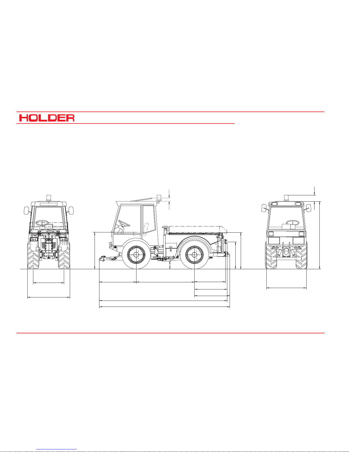
T ractor Dimensions
Sketch
g
b
d
c
100
(3,9")
200
(7,8")
3980-4100
(156,5-161,4")
3900-4020
(153,5-158,3")
1110
1030
970
(43,1")
(40,5")
(38,2")
1827
(72")
1040-1160
(40,9-45,6")
1090
(Cab for 1 person)
1250
(42,9")
(49,3")
(Cab for 2 persons)
f
a
e
Bild_194
Data in brackets are American dimensions
Page 19

Operating Instructions
145 052 17
C 9700 ... C 9.88 H
Technical data
Trailer Coupling
Tires Type Overall Height Avg. Height of
Seat
Ground
Clearance
Lowest Position Highest Position Height of Body
a
mm (Inches)
b
mm (Inches)
c
mm (Inches)
d
mm (Inches)
d
mm (Inches)
g
mm (Inches)
10
.
5-18 MPT S
524-31-6 2130 (83.8) 1050 (41.3) 230 (9) 575 (22.4) 975 (38.2) 1130 (44.5)
10
.
5-18 MPT
524-31-1 2130 (83.8) 1050 (41.3) 230 (9) 575 (22.4) 975 (38.2) 1130 (44.5)
36x13
.
50-15
524-31-8 2100 (82.5) 1020 (40.1) 200 (7.9) 545 (21.3) 945 (37.1) 1095 (43.1)
400/60-15
.
5
524-31-5 2095 (82.3) 1030 (40.5) 195 (7.5) 540 (21.2) 940 (37) 1095 (43.1)
33x12,50-R15 524-31-7 2090 (82.2) 1020 (40.1) 190 (7.3) 535 (21.0) 935 (36.6) 1090 (42.9)
33/18LL-16.1 524-31-9 2090 (82.2) 1020 (40.1) 190 (7.3) 535 (21.0) 935 (36.6) 1090 (42.9)
33x12
.
50-15
524-31-4 2075 (81.4) 1010 (39.7) 180 (7) 525 (20.6) 925 (36.3) 1075 (42.3)
33x15
.
50-15
524-31-3 2075 (81.4) 1010 (39.7) 180 (7) 525 (20.6) 925 (36.3) 1075 (42.3)
31x15
.
50-15
524-31-2 2065 (81.1) 980 (38.6) 165 (6.4) 510 (20) 910 (35.8) 1060 (41.7)
T able of Dimensions
Page 20

C 9700 ... C 9.88 H
Operating Instructions
18 145 052
Technical data
Tires
Min. Turning
Radius to DIN
7020
(measured at
outermost
point of
vehicle)
Normal Track Width
(
Flange size
1034
)
With Hub Spacers
Type 5234-80= 45 mm Type 526-34-70= 80 mm
Track Width e Overall Width f Track Width e Overall Width f Track Width e Overall Width f
m
min.-mmmax.-
mm
min.
-
mm
max.-mmmin.-mmmax.-
mm
min.
-
mm
max.-mmmin.-mmmax.-
mm
min.
-
mm
max.-
mm
36x13.50-15
7.28 m
f. track w. 1084
- 1084 - 1439 1090 1174 1445 1529 1160 1244 1515 1599
10.5-18 MPT S
7.10 m
f. track w. 960
960 1124 1230 1394 1124 1140 1320 1484 1120 1284 1390 1554
10.5-18 MPT
7.14 m
f. track w. 1034
1034 1050 1304 1320 1050 1214 1394 1410 1194 1210 1464
1480
400/60-15.5
7.30 m
f. track w. 1070
- 1070 - 1470 1106 1160 1506 1560 1176 1230 1576 1630
33x12.50 R15
7.15 m
f. track w. 1000
1000 1084 1320 1404 1090 1174 1410 1494 1160 1244 1480 1564
33x12.50-15
7.15 m
f. track w. 1000
1000 1084 1320 1404 1090 1174 1410 1494 1160 1244 1480 1564
33x15.50-15
7.24 m
f. track w. 1124
* 992 1124 * 1382 1514 1052 1214 1442 1604 1122 1284 1512 1674
33/18LL-16.1
7.45 m
f. track w. 1164
- 1164 - 1636 - 1254 - 1726 - - - -
31x15.50-15
7.30 m
f. track w. 1124
* 962 1124 * 1332 1494 1052 1214 1422 1584 1122 1284 1492 1654
*Snow chains not possible
* With track spacer type 526-34-75 (15 mm per wheel)
Track Widths
Page 21

Operating Instructions
145 052 19
C 9700 ... C 9.88 H
Technical data
All Tractors Weight in kg
Permissible total weight
4500 kg (9920.6 LBS)
Permissible load on front axle
*
2660 kg - 2700 kg
(5864 LBS - 5952 LBS)
Permissible load on rear axle
*
2660 kg - 2700 kg
(5864 LBS - 5952 LBS)
Permissible supporting load on
trailer hitch
800 kg (1764 LBS)
* With 33x12.50 R15 tires
Accessories Total Front Rear
Creep speed gear
13 kg
(28.6 LBS)
10 kg
(22 LBS)
3 kg
(6.6 LBS)
Rear lift
77 kg
(169.7 LBS)
-25 kg
(-55 LBS)
102 kg
(224.8 LBS)
Loading platform
75 kg
(165.3 LBS)
0 k g
(0 LBS)
75 kg
(165.3 LBS)
Weights w/o loading platform and rear lift
Tires 36x13.5-15
10.5-18 MPT
400/60-15.5
33x12.50 R15 33x12.50-15
31x15.50-15
33x15.50-15
33/18LL-16.1
Empty weight (incl.
driver 75 kg)
C9700
C9.72
C9700H
C9800H
C9.72H
C9.78H
C9.83H
C9.88H
C9700
C9.72
C9700H
C9800H
C9.72H
C9.78H
C9.83H
C9.88H
C9700
C9.72
C9700H
C9800H
C9.72H
C9.78H
C9.83H
C9.88H
C9700
C9.72
C9700H
C9800H
C9.72H
C9.78H
C9.83H
C9.88H
C9700
C9.72
C9700H
C9800H
C9.72H
C9.78H
C9.83H
C9.88H
C9700
C9.72
C9700H
C9800H
C9.72H
C9.78H
C9.83H
C9.88H
Total: k g
2430
(5351)
2620
5776)
2440
(5319)
2630
(5198)
2390
(5269)
2580
(5687.8)
2380
(5246.9)
2570
(5665.8)
2410
(5313.1)
2600
(5732)
2470
(5445.4)
2660
(5864.2)
Front: kg
1275
(2810.8)
1390
(3064.4)
1280
(2821.8)
1395
3015)
1255
(2766.7)
1370
(3020.3)
1250
(2755.7)
1365
(3009.3)
1265
(2788.8)
1380
(3042.3)
1295
(2855)
1410
(3108.5)
Rear: kg
1155
(2546.3)
1230
(2711.6)
1160
(2551.3)
1235
(2122.6)
1135
(2502)
1210
(2667.5)
1130
(2491.2)
1205
(2656.5)
1145
(2524.3)
1220
(2689.6)
1175
(2590.4)
1250
(2755.7)
Weights
Page 22

C 9700 ... C 9.88 H
Operating Instructions
20 145 052
Technical data
Tires
The pressure can deviate, depending on the make and use of the tyres – observe the instructions of the tyre manufacturers.
Type of Tire Ply Profile Tube Wheel Weights
Inflation Pressure
(in bar)
Empty weight max. loading
front rear Type Weight
10.5-18 MPT S 6 Cleat profile yes 1.5 (22 PSI) 1.75 (25 PSI) 1.9 (27 PSI) 524-34-1 approx. 45 kg (100 LBS)
10.5-18 MPT 6 Cleat profile yes 1.5 (22 PSI) 1.75 (25 PSI) 1.9 (27 PSI) 524-34-1 approx. 45 kg (100 LBS)
31x15.50-15* 8 Profile no 2.0 (29 PSI) 3.2 (46 PSI) 3.2 (46 PSI) 524-34-1 approx. 45 kg (100 LBS)
33x15.50-15 4 Profile no 1.0 (14 PSI) 1.6 (23 PSI) 1.6 (23 PSI) 524-34-1 approx. 45 kg (100 LBS)
33x12.50-15 6/8 (M+S)/Profile no 1.4 (20 PSI) 1.9 (27 PSI) 2.0 (29 PSI) 524-34-1 approx. 45 kg (100 LBS)
33x12.50-R15* 6 M + S no 1.6 (23 PSI) 2.5 (36 PSI) 2.5 (36 PSI) 524-34-1 approx. 45 kg (100 LBS)
36x13.50-15 4 Lawn no 1.0 (14 PSI) 1.2 (17 PSI) 1.4 (20 PSI) 524-34-1 approx. 45 kg (100 LBS)
400/60-15.5 6 Profile yes 1.8 (26 PSI) 1.8 (26 PSI) 2.0 (29 PSI) 524-34-1 approx. 45 kg (100 LBS)
33/18LL-16.1 10 Lawn no 1.2 (17 PSI) 1.8 (26 PSI) 2.0 (29 PSI) 524-34-1 approx. 45 kg (100 LBS)
NOTE: Observe prescribed inflation pressure with maximum axle load and when driving on roads.
* NOTE: Admissible maximum axle loading is 2660 kg.
Page 23

Operating Instructions
145 052 21
C 9700 ... C 9.88 H
Technical data
Engine Specifications
C 9700/9.72
C 9700/9.72H
C 9800/9.73H C 9.78H C 9.88H
Manufacturer Deutz AG Deutz AG Deutz AG Deutz AG
Type BF4M1011 BF4M1011F BF4M2011 BF4M2011
Mode of operation Four-stroke Diesel Four-stroke Diesel Four-stroke Diesel Four-stroke Diesel
Number of cylinders 4 4 4 4
Cubic capacity 2914 2914 3108 3108
Fuel consumption
223g/KW-h at
1500-1750 rpm
222g/KW-h
at 1750-1850 rpm
216g/KW-h
at 1750-1850 rpm
216g/KW-h
at 1550-1650 rpm
Rated speed
2500
rpm
2600 rpm
2500 rpm 2800 rpm
Maximum idling speed 2600 rpm 2750 rpm
2750
rpm
3050 rpm
Minimum idling speed 900 rpm 900 rpm 900 rpm 900 rpm
Power at n=2800 rpm 53.5 KW (72 HP) 61 KW (83 HP) 57 KW (78 HP) 65 KW (88 HP)
Page 24

C 9700 ... C 9.88 H
Operating Instructions
22 145 052
Technical data
Transmission Unit Gearbox
Hydrosta-
tic Drive
Hydrosta-
tic Drive
Hydrosta-
tic Drive
Dual
Drive
Dual
Drive
Dual
Drive
Engine Output
kW 53.5
53.5
57
61 65
53.5
57
61 65
Engine speed
rpm 2500 2500 2600 2800 2500 2600 2800
Tires Type
36x13.50-15
524-31-8 km/h 36.8 30.8 32.0 34.4 38.4 39.9 43.0
10.5-18 MPT
524-31-1/-6 km/h 35.9 30.1 31.3 33.7 37.6 39.1 42.1
400/60-15.5
524-31-5 km/h 34.1 28.6 29.7 32.0 35.7 37.1 40.0
33x12.50 R15
524-31-7 km/h 33.3 27.9 29.0 31.2 34.8 36.2 39.0
33x12.50-15
524-31-4 km/h 32.4 27.2 28.3 30.4 33.9 35.3 38.0
33x15.50-15
524-31-3 km/h 32.4 27.2 28.3 30.4 33.9 35.3 38.0
33/18LL-16.1
524-31-9 km/h 31.8 26.7 27.8 29.9 33.3 34.7 37.3
31x15.50-15
524-31-2 km/h 30.5 25.1 26.1 28.1 31.3 32.6 35.1
Theoretical Driving Speeds
Page 25

Operating Instructions
145 052 23
C 9700 ... C 9.88 H
Technical data
Assembly Suppl. Information Description
Mechanical gearbox
16 forward gears/16 reverse gears with planetary axles
Hydrostatic drive
Infinitely variable driving speed, 2 mechanical speed ranges
Power take-offs
2 PTOs (front and rear) Rotating Direction: clockwise when looking at
end of shaft
- RPM, front 540 rpm at 2200 engine rpm, 1000 rpm at 2390 engine rpm
- RPM, rear 1000 rpm at 2360 engine rpm
- Wedge shaft profile 1 3/8 " (6) DIN 9611
PTO clutch Multiple disk wet clutch
Differential lock Acts simultaneously on front and rear axles
Fuel system
Fuel tank Diesel fuel 86 l (22.7 USGAL.)
Tec hnical Data/Filling Quantities
Page 26

C 9700 ... C 9.88 H
Operating Instructions
24 145 052
Technical data
Assembly Suppl. Information Description
Steering
- Type Hydrostatic with 2 double-acting steering rams
- Steering valve Orbitrol OSPC 125 LS
Brakes
- Service brake Multiple-disk brakes, wet, acting on all 4 wheels
- Activation Hydraulic
- Parking brake Multiple-disk brakes, wet, acting on all 4 wheels
- Activation Mechanical
Trai ler hi tch
- Make Cramer, height-adjustable
Front lift
- Make 3-point, upper link adjustable
- Mounting Category I and II
- Lifting power 27000 N (measured at installation points)
- Cylinders 2 double-acting cylinders
Page 27

Operating Instructions
145 052 25
C 9700 ... C 9.88 H
Technical data
Assembly Suppl. Information Description
Rear lift
- Model HOLDER 3-point standard
- Mounting Category I and II
- Lifting power 15700 N (at installation points)
- Cylinders 2 double-acting cylinders
Flatbed body
- Dimensions L x B x H 1530 x 1140 x 215 mm
- Payload 1400 kg
Drive Hydraulics
Variable pump Hydromatik
- Model A11 VG 50 EP / A4 VG 40 EP
- Flow rate 160 l/min
- Operating pressure 300 bar (max. 350 bar) / 380 bar (max. 430 bar)
Variable motor Hydromatik
- Model A6 VM 55 EP
- Displacement 26.1 - 55 cm
3
/rev
Hydraulic oil tank 19 l
Page 28

C 9700 ... C 9.88 H
Operating Instructions
26 145 052
Technical data
Assembly Suppl. Information Description
Hydraulics for implements
(with steering)
Pump Sundstrand
- Make -
- Flow rate 17 cm
3
/rev (42.5 l/min at 2500 engi ne r pm)
- Operating pressur e 180 -190 bar
Hydraulic oil tank 45 l (11.89 GAL.)
Electrical System
- Operating voltage 12 VDC
- Batter y 12 V / 88 Ah
- A/C alter nat or 14 V / 60 A
- Star ter 12 V / 2.4 kW
Whole Vehicle
- Ambient temperature range - 30° to + 50°C
Page 29

Operating Instructions
145 052 27
C 9700 ... C 9.88 H
Technical data
Noise Level
The tractor emits the following noise level (measured at the
driver's ear) according to EU Standard 77/311/EEC;
measurement according to Appendix II.
T able of Noise Levels and Absorption Rating
Exhaust Gas Identification
The absorption rating is stated on the identification plate.
Model Engine Type Engine Output Noise Level dB(A) Absorption rating
Cabin
open*
Cabin
closed
C 9700 BF4M1011 53.5 kW (72 HP) 79 78 2.1
C 9700 H BF4M1011 53.5 kW (72 HP) 79 78 2.1
C 9800 H BF4M1011F 61 kW (83 HP) 79 78 2.1
C 9.72 BF4M1011 53.5 kW (72 HP) 79 78 2.1
C 9.72 H BF4M1011 53.5 kW (72 HP) 79 78 2.1
C 9.83 H BF4M1011F 61 kW (83 HP) 79 79 2.1
C 9.78 H BF4M2011 57 kW (78 HP) 79 79 1.8
C 9.88 H BF4M2011F 65 kW (88 HP) 79 79 2.0
*Roof vent and side window open
Page 30

C 9700 ... C 9.88 H
Operating Instructions
28 145 052
1
2
3
4
5
6
7
8
9
10
11
12
13
15
14
Description
Views of T ractor
Front Left View
1 Turn signal, position
light
2 Headlight, top
3 Driver's cab
4 Dump body (dump)
5 Rear of vehicle
6 Engine oil dipstick
7 Battery isolating switch
8 Rear axle
9 Hydraulic oil tank and
filler neck (drive
hydraulics)
10 Front axle
11 Hydraulic couplings for
implements*
12 Front lift - lower link
support
13 Upper link support
14 Headlight
15 Windshieldwiper /
washer
* Option
Page 31

Operating Instructions
145 052 29
C 9700 ... C 9.88 H
Description
432
5
6
7
8
9
10
11
12
13
14
15
17
1
16
Bild_002
Tractor
Rear Right View
1 Dump Body
2 Fuel filler neck
3 Oil filler neck
for implement hydraulics
4 Intake screen
for fresh air blower
5 Support for
rotating beacon
6 Flood light*
7 Driver's cab
8 Front part of tractor
9 Front axle
10 Intake screen for drive
oil cooler
11 Air vent for drive oil
cooler
12 Oil level gauge for
implement hydraulics
and steering
13 Rear axle
14 Hydraulic couplings for
implements*
15 Trailer hitch
16 Socket for trailer lighting
17 Tail light, LH/RH
* Option
Page 32

C 9700 ... C 9.88 H
Operating Instructions
30 145 052
Description
* Option
Driver's Station
Operating controls
1 Light switch
2 Differential lock switch
3 Pressure gauge for hydraulic carrier*
4 Steering wheel
5 Brake fluid reservoir
6 Control lever for dump support*
7 Implement* control lever
8 Multi-function display
9 Multi-function lever* (front lift and direction of travel)
1 0 Digital instrument switch (ground speed in km/h or
PTO rpm)
1 1 Hazard warning flasher switch
1 2 Heater fan switch
1 3 Power Socket
1 4 Lock switch for circulating oil* or priority flow valve*
15 Lock switch for tilt control
16 Preheat/starter switch
1 7 Hydraulic carrier* control
1 8 Passenger seat
(water reservoir for windshield washer system is
located under the seat)
1 9 Parking brake lever
2 0 Driver's seat
(warning triangle is mounted behind the seat)
21 Accelerator pedal
2 2 Steering wheel tilt adjustment knob
23 Driving program switch
2 4 Inch knob for ground speed
2 5 Turn signal lever
Page 33

Operating Instructions
145 052 31
C 9700 ... C 9.88 H
Description
3
2
1
4
5
6
7
8
9 10
11
12
13
14
15
16
17
18
19
22
21
20
24
25
23
Page 34

C 9700 ... C 9.88 H
Operating Instructions
32 145 052
Description
1
2
3
4
56
7
9
8
10
Bild_004
* Option
Implement* and Engine Controls (Details)
1 Control lever for dump/rear lift*
2 Control lever functions plate
3 Multi-function lever functions plate
4 Multi-function lever* (front lift and travel direction)
5 Hand throttle
- Outer ring for fine adjustment:
Turn clockwise to decrease rpm
Turn counter-clockwise to increase rpm
- Inner knob for coarse adjustment:
Pull out to increase rpm
Push in to decrease rpm
Push in fast for emergency reset to idling rpm
6 Preheat/starter switch
7 Lock knob for longitudinal motion of multi-function
lever:
- Depressed - locked
- Centre position - free movement
- Pulled out - float position
8 Lock knob for lateral motion of multi-function lever
9 Lock knob for longitudinal motion of control lever
1 0 Lock knob functions plate
Page 35

Operating Instructions
145 052 33
C 9700 ... C 9.88 H
Description
1
Bild_193
2
3
Multi-function Lever
NOTE
Various types of multi-function levers can be
installed.
Multi-function Lever (V ariant 1)
1 Multi-function lever without forward reverse selector
lever (Forward-reverse selector installed on instrument board)
2 Forward/reverse selector lever
3 Note plate
Driving direction
Page 36

C 9700 ... C 9.88 H
Operating Instructions
34 145 052
Description
* Option
Multi-function Lever* (V ariant 2)
NOTE
The coloured buttons control the function of the
implements attached to the related hydraulic couplings
1 Multi-function lever
2 Blue hydraulic couplings on
3 Blue hydraulic couplings off - float position
4 LED indicator, red or green
5 Functions off
6 LED indicator, red
7 Functions on
8 LED indicator, red
9 LED indicator, red or green
1 0 Yellow hydraulic couplings, off
1 1 Green hydraulic couplings off - float position
1 2 Green hydraulic couplings on
1 3 Yellow hydraulic couplings on
5
6
7
8
9
10
11
12
13
1
2
4
3
blue yellow
green
Bild_020
Page 37

Operating Instructions
145 052 35
C 9700 ... C 9.88 H
Description
* Option
8
7
1
6
2
4
5
3
Bild_068
1
2
3
Bild_021
4
Multi-function Lever* (V ariant 3)
1 Forward direction arrow (illuminated if selected)
2 Reverse direction arrow (illuminated if selected)
3 Forward/reverse selector switch (left for forward -
right for reverse)
4 Multi-function lever
Multi-function Lever* (V ariant 4)
1 Forward direction arrow (illuminated if selected)
2 Reverse direction arrow (illuminated if selected)
3 Forward/reverse selector switch (left forward - right
reverse)
4 Front lift float position pushbutton
5 Multi-function lever
6 Front lift pushbutton
7 Yellow pushbutton, left (front when looking forward)
(movements at yellow hydraulic couplings on)
8 Yellow pushbutton, right (front when looking forward)
(movements at green hydraulic couplings on)
Page 38

C 9700 ... C 9.88 H
Operating Instructions
36 145 052
Description
1
2
3
Bild_005
1
3
2
* Option
Foot Pedals
1 Inch pedal (clutch pedal if gearbox is fitted)
2 Brake pedal
3 Accelerator pedal
Hydraulic Carrier* Control (P ower Lifter)
1 Pressure adjuster
2 ON-OFF label
3 Star knob for turning on/off
Page 39

Operating Instructions
145 052 37
C 9700 ... C 9.88 H
Description
1
4 3
2
1
Bild_069
Operating Controls Behind the Seat
1 PTO clutch lever, ON-OFF
2 Device selector lever:
- Position for dump on
3 - Position for rear lift on
4 Emergency start
(Hydrostatic Drive with Dual-Drive only)
Drive Range Pre-selection Lever between Seats
1 Drive range pre-selection lever
2 Drive range label
- Position S - Fast Driving range
(low tractive force)
- Centre position 0 - Drive off - Towing
- Position L - Slow Working range
(high tractive force)
Page 40

C 9700 ... C 9.88 H
Operating Instructions
38 145 052
Taking into Service
1
2
1
2
Bild_009
Front PTO Selector
1 PTO rpm label
- Top position (up) - 540 rpm
- Centre position - Neutral
- Lower position (down) - 1000 rpm
2 PTO selector lever
Heater
1 Heater temperature control
2 Heating temperature label
- lever up - warmer
- lever down - cooler
Page 41

Operating Instructions
145 052 39
C 9700 ... C 9.88 H
Taking into Service
1
18
2
3
4
5
6
7
17
16
15
14
13
12
891011
Legend for Multi-function
Display
1 Display for
- Ground speed in km/h or
- PTO rpm x10
2 Position light indicator
3 High beam indicator
4 Turn signal indicator
5 Turn signal indicator
for trailer 1
6 Turn signal indicator
for trailer 2
7 Preheating indicator
8 Fuel gauge
9 Hour meter
10 Tachometer
11 Engine temperature gauge
12 Spare
13 Differential lock engaged
indicator
14 Parking brake engaged indicator
15 Engine oil temperature indicator
16 Engine oil pressure indicator
17 Battery charge indicator
18 Hydraulic oil temperature gauge
Page 42

C 9700 ... C 9.88 H
Operating Instructions
40 145 052
Description
Bild_17
6
1
2
21
3
Bild_017
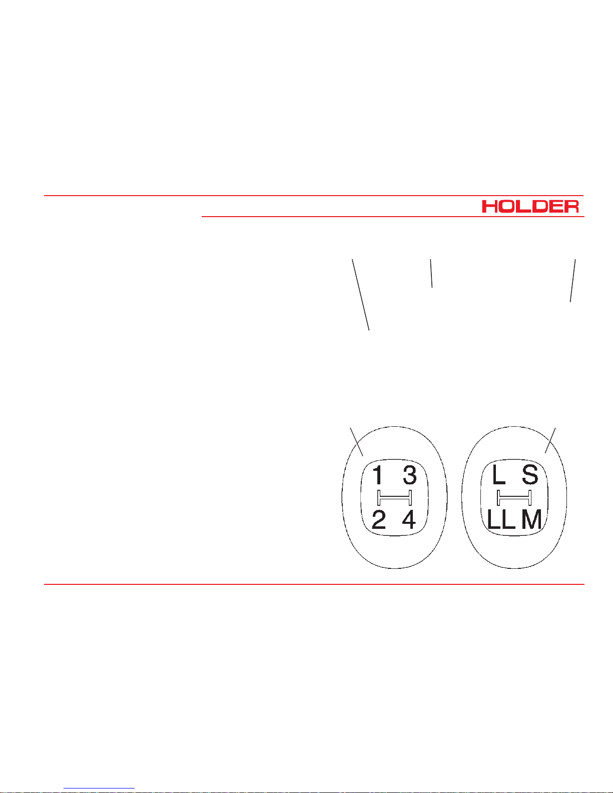
Controls for Mechanical Gearbox
1 Gearshift lever (left looking forward) with 4 synchroni-
zed gears 1-2-3-4
2 Range selector lever (right looking forward)
with 4 speed ranges:
S - Highway driving
M - Medium speed
L- Slow speed
LL - Very slow speed
3 Gearshift label
Page 43

Operating Instructions
145 052 41
C 9700 ... C 9.88 H
Description
1
4
3
2
2
Bild_01
3
1
3
4
5
Controls on Cabin Console at Front Left
1 Front wiper/washer switch
2 Rear wiper/washer switch
3 Sun blind
4 Air vent nozzle
Controls on Cabin Console at Front Right
1 Rotating beacon switch
2 Fresh air blower switch, top
3 Headlight switch, top
4 Rear floodlight switch
5 Air vent nozzle
Page 44

C 9700 ... C 9.88 H
Operating Instructions
42 145 052
Description
1
2
4
3
Controls in Cabin at Rear
1 Interior light
2 Sun visor
3 Roof hatch handle
4 Roof hatch
Page 45

Operating Instructions
145 052 43
C 9700 ... C 9.88 H
Description
4
Bild_098
1
2
3
6
5
Location of Plates and
Labels
Identification Plates
1 Variable motor type plate
2 Engine type plate
3 Variable pump type plate
4 Machine type plate
5 Chassis Serial Number
(on front RH support
looking forward)
6 Cabin type plate
Page 46

C 9700 ... C 9.88 H
Operating Instructions
44 145 052
Description
2
Mounting Instructions for License Plate
- Install the front license plate (1) above the upper link
support at the front cabin wall.
- Install the rear license plate (2) at the rear below the
left tail light.
Page 47

Operating Instructions
145 052 45
C 9700 ... C 9.88 H
Description
Assembly Suppl. Information Dimension /Order No./Type
Charcoal filter For cabin ventilation 131667
Pneumatic braking system For trailer operation 526-34-60, 524-34-63
Rear lift 524-51-4
Oil heating element from - 20°C 230 VAC
Hydraulic carrying equipment (power lifter) 524-80-19
Creep speed gearbox with hand lever
Super
For mechanical gearbox only
5262-11, 524-62-70
Variable pump for implements 0-100 l /min adjustable 524-80-34
- Pump
- Delivery capacity 0-40 cm³/rev
- Flow rate 0-100 l/min
- Maximum pressure 280 bar
Overview of Options and Variants
Page 48

C 9700 ... C 9.88 H
Operating Instructions
46 145 052
Description
Assembly Suppl. Information Dimension /Order No./Type
Power hydraulics 75 l/min fixed displacement 524-80-35
- Pump Mounted on drive pump Gear pump
- Delivery capacity 22 cm³/rev
- Flow rate 75 l/min
- Maximum pressure 210 bar
Flow divider I. Circuit 524-80-25
- Pump Standard pump
- Delivery capacity 17 cm³/rev
- Flow rate 0-25 l/min
- Maximum pressure 200 bar
Flow divider II. Circuit 524-80-47
- Pump Tandem pump
- Delivery capacity 14 cm³/rev
- Flow rate 0-25 l/min
- Maximum pressure 200 bar
Page 49

Operating Instructions
145 052 47
C 9700 ... C 9.88 H
Description
Assembly Suppl. Information Dimension /Order No./Type
Circulating oil device rear, uncontrolled 524-80-45
- Pump Tandem pump
- Delivery capacity 14 cm³/rev
- Flow rate 35 l/min
- Maximum pressure 200 bar
Reduction gearbox
Reduction of rear PTO rpm to
540 rpm
526-62-1
Page 50

C 9700 ... C 9.88 H
Operating Instructions
48 145 052
Description
1
3
2
4
5
6
7
Accessories
The tractor is delivered with the following accessories:
1 Operating Instructions
2 Bio-Pass for certification of filling with environment-
friendly hydraulic oil
3 Key holder
4 2 ignition keys
5 4 door keys
6 Upper link
7 2 reducers for category I implements
Page 51

145 052 49
C 9700 ... C 9.88 H
Operating Instructions
Taking into Service
Daily Checks and Activities before T aking
into Service
If damages or defects are found during the following checks,
they must be eliminated before taking the vehicle into
service. Do not operate the tractor before proper repairs are
carried out. Safety and protective devices should not be
removed or disabled. Fixed specified settings may not be
changed.
Before starting work, make yourself familiar with all the
functions and protective devices of the tr actor.
Checking and Cleaning the Cooler and Radiator
Screen Guards
NOTE
- Check if the mud guards (2, 3, 4, 5 and 6)
are clean.
- Clean the mud guards if necessary. The
guard (6) can be pulled out laterally to the
left after releasing the bayonet screw (7)
and then cleaned easily .
- The air intake of the air filter (1) must be
clean.
1 2
34
5
6
Bild_071
7
6
Page 52

C 9700 ... C 9.88 H
Operating Instructions
50 145 052
Taking into Service
T urning on the Battery Isolating Switch
NOTE
The battery can be switched off completely
with the removab le key.
- Insert the key (1) in the battery isolating switch and
set it to the vertical position.
The battery circuit is turned on.
Checking Engine Oil Level
NOTE
Check the engine oil level only when the
tractor is on level ground.
- Let the engine run approx. 2 minutes with the heat
shut-off valve open.
- Stop the engine and pull the oil dipstick (1) out after
approx. 1 minute .
- The oil level should be between the Min (2) and Max
marking (3).
- If necessary, fill oil according to the maintenance
manual.
ATTENTION
Do not fill too much oil.
1
Bild_022
1
2
3
Page 53

Operating Instructions
145 052 51
C 9700 ... C 9.88 H
Taking into Service
Checking the Trailer Hitch (Optional), if required
- Check the trailer hitch for proper condition and wor-
king. Carry out the check according to the instructions
in the section "Operating the Trailer Hitch".
Checking Tire Inflation Pressure
NOTE
Your tractor can be equipped with different
types of tires. The specified inflation pressure
for your tires is given in the table entitled
"Tires" in the technical data section.
- Check the inflation pressure of all four tires. All tires must
have the same pressure. If the pressure is too low, the
rolling resistance increases. This causes an increase in
fuel consumption and tire wear, the driving characteristics
become poorer.
DANGER
If the inflation pressure is too high, the tires
can explode.
- The tires should not be damaged or worn.
- Have damaged tires replaced without delay. Due to the
longer braking distance the risk of an accident is increased.
Page 54

C 9700 ... C 9.88 H
Operating Instructions
52 145 052
Taking into Service
1
2
Bild_026
2
1
Bild_027
Checking the Drive Hydraulics Oil Level
- Withdraw the oil dipstick (1).
- The oil level must be at the marking (2).
- Top up oil as specified in the maintenance manual.
Checking the Implement Hydraulics Oil Level
- Retract all hydraulic cylinders.
- Check the oil level at the sight glass (2).
The oil level must be at the centre (1) of the sight
glass.
- Top up oil as specified in the maintenance manual.
Page 55

Operating Instructions
145 052 53
C 9700 ... C 9.88 H
Taking into Service
Filling Fuel
- If necessary, read the fuel level (1) on the multi-
function display.
CAUTION
Danger of fire when handling fuels. Turn off
the engine. Do not fill any fuels in the vicinity
of naked flames, ignition sparks or hot engine
parts. Do not smoke during refuelling.
- Remove the fuel tank filler cap (2).
- Top up Diesel fuel as specified in the maintenance
manual.
Filling quantities ............approx. 86 litres (22.7 USGAL.)
- Refit the filler cap (2).
2
Bild_028
Bild_073
1
Page 56

C 9700 ... C 9.88 H
Operating Instructions
54 145 052
Taking into Service
1 2
34
Checking the Brake Fluid Level
- Check the brake fluid level at the brake fluid reservoir
(2).
- The brake fluid level must be between the Min and
Max marking at the reservoir.
- Top up the brake fluid as specified in the maintenance
manual.
Adjusting the Steering Wheel
NOTE
The tilt of the steering wheel can be set to a
comfortable position.
DANGER
Do not adjust the steering wheel while driving.
- Loosen the star knob (3).
- Pull the slider (4) to the right.
- Adjust the tilt of the steering wheel (1) and release the
slider again.
- Retighten the star knob.
Page 57

Operating Instructions
145 052 55
C 9700 ... C 9.88 H
Taking into Service
Adjusting the Driver's Seat
1 Backrest
2 Adjustment knob for lumbar padding
3 Backrest adjustment
4 Weight adjustment
5 Horizontal cushioning
6 Horizontal adjustment
DANGER
Do not adjust the seat while driving. Risk of
accidents!
- Adjust the seat so that all controls can be reached
and operated safely.
NOTE
Observe the operating manual for the seat
supplied with your tractor .
Adjusting the Lumbar Padding
- Sit down on the seat and lean against the backrest
(1).
- Turn the adjustment knob for lumbar padding (2) until
the most comfortable position is reached.
1
2
3
456
Bild_010
Adjusting the Backrest
- Pull the tilt lever (3) up.
- Adjust the inclination of the backrest with your back.
- Release the tilt lever.
Page 58

C 9700 ... C 9.88 H
Operating Instructions
56 145 052
Taking into Service
1
2
3
456
Bild_010
Adjusting the Driver's Weight
- Sit down on the driver's seat.
- Pull the weight adjustment handle (4) up.
NOTE
An alert sounds. The seat is automatically
set to the weight of the driver; The aler t
ceases.
- Release the lever.
Adjusting the Horizontal Suspension
- Push the horizontal suspension lever (5) back:
the seat suspension is unlocked in horizontal direction.
- Move the horizontal suspension lever (4) forward: the
seat suspension is locked in the horizontal direction.
Adjusting the Seat Horizontally
- Pull the horizontal adjustment lever (6) up.
- Slide the seat horizontally forward or rear to the
suitable seat position.
- Release the horizontal adjustment lever.
Page 59

Operating Instructions
145 052 57
C 9700 ... C 9.88 H
Taking into Service
Adjusting the Passenger Seat
1 Backrest
2 Weight adjustment
3 Backrest tilt adjustment
Adjusting the Weight
- The weight should be adjusted when the passenger
seat is unoccupied.
- Press the weight adjustment knob (2) from the top
down until the weight on the scale is reached. The
weight can be adjusted in 9 stages of 50 to 130 kg.
- Release the knob when your weight is indicated.
NOTE
Only push the knob from the top down.
- Press the knob at the bottom against the stop - the
weight adjuster will automatically reset the seat to 50 kg.
- Release the knob.
Adjusting the Backrest Tilt
- Pull the tilt lever (3) up.
- Adjust the inclination of the backrest with your back.
- Release the tilt lever.
NOTE
If the backrest tilt is adjusted, the horizontal
position of the seat will simultaneously
adjusted to the changed seat position.
1
2
3
Page 60

C 9700 ... C 9.88 H
Operating Instructions
58 145 052
Taking into Service
Filling Washing Water
NOTE
The washing water reservoir for the windshield
washer is located beneath the passenger
seat.
- Tilt the seat forward.
- Open the filler cap (1) and add washing water into the
reservoir (2).
Filling capacity............approx. 2.5 litres (0.66 USGAL.)
Checking the Lights and Rear View Mirr or
- Check that the lighting is functioning properly. Carry
out the check according to the instructions in the
section entitled "Lights".
- Adjust the rear view mirror so that the roadway behind
the tractor and the working area are easily seen.
1
2
Page 61

Operating Instructions
145 052 59
C 9700 ... C 9.88 H
Taking into Service
Starting the Engine
Instructions before Starting the Engine
DANGER
Do not start or run the engine in enclosed
spaces. Danger of poisoning through exhaust
gases!
Instructions before Starting
CAUTION
Before starting, check to ensure no one is in
the vicinity of the tractor.
ATTENTION
Do not use a starting aid such as Star tpilot
or similar means. Turn off the drive or driven
attaching implements.
CAUTION
Start the engine only from the driver's station.
Page 62

C 9700 ... C 9.88 H
Operating Instructions
60 145 052
Taking into Service
Starting the Engine
- Shift the gearshift lever (gearbox) to neutral.
- Set the forward/reverse selector lever (1) to the
neutral position (centre).
- Depress the clutch pedal (gearbox) or inch pedal
(hydrostatic drive).
NOTE
The engine can only be started if the pedal is
fully depressed (starting safety switch).
- Set the hand throttle (2) to idle (push in fully).
- Insert the ignition key and turn the preheat/starter
switch (3) to position 1.
2
Bild_113
3
Bild_180
1
1
Page 63

Operating Instructions
145 052 61
C 9700 ... C 9.88 H
Taking into Service
3
4
8
7
6
Bild_033
5
NOTE
The battery charge indicator (8), engine oil
pressure indicator (7), parking brake indicator(6) (if parking brake is engaged) and the
red indicator for km/h or x10 (3) in the multifunction display come on.
- Turn the ignition key to position 2 to preheat the
engine. The preheating indicator (4) comes on.
NOTE
When starting at low temperatures, hold the
ignition key longer (approx. 1 minute) in
position 2.
- When the preheating indicator goes out, turn the
ignition key to position 3 to start the engine.
ATTENTION
Operate the starter for a maximum of 20 seconds. W ait one minute, then repeat the starting procedure. Repeat the starting procedure
only twice at most. In case the engine does
not start, carry out a troub leshooting according to the section entitled "Problems, Causes,
Remedy".
Page 64

C 9700 ... C 9.88 H
Operating Instructions
62 145 052
Taking into Service
1
Bild_195
2
Starting the Engine with Automatic Preheating*
Start-up
- Turn the ignition key to position 1.
- The engine will be preheated. At temperatures under
+10° the yellow lamp (1) and the preheating indicator
light (2) comes on.
- When the yellow lamp (1) goes off, turn the ignition
key to position 3 to start the engine.
- The automatic preheating turns off 2 minutes after the
engine start and the preheating indicator light (2) goes
off.
NOTE
If the engine does not start, the yellow lamp
(1) goes off after about 10 s and the preheating
is switched off.
* Installed for a short time only
Page 65

Operating Instructions
145 052 63
C 9700 ... C 9.88 H
Taking into Service
- Release the ignition key as soon as the engine turns
over. The battery charge indicator (8) and the engine oil
pressure indicator (7) will go out.
- Set the engine speed with the hand throttle (1) or
accelerator pedal to the desired RPM (5) .
3
4
8
7
6
Bild_033
5
Checking the Brakes and Steering for Proper Operation
- Make a short trial run and check the steering and
brakes for proper operation.
DANGER
Do not drive a tractor with a defective steering
and/or braking system.
1
Bild_032
Page 66

Page 67

145 052 65
C 9700 ... C 9.88 H
Operating Instructions
Operation
Before Starting to Drive
When driving on public highways, observe the regulations
of the highway code.
• When following a curve with a trailer or other attachments, don't forget to take the added length and drag into
consideration.
DANGER
Parts of implements posing a danger to traffic
must be covered before driving or identified
with warning signs.
• Switch off the differential lock when travelling along a
curve.
• When driving on slopes, drive downhill if possible; if
you have to turn, turn only when driving uphill.
• On steep slopes you can improve traction by activating the differential lock.
• Drive across slopes only in accordance with the notes
at the end of this chapter.
Driving Safety Rules
• Drive the tractor only from the driver's station with the
cab doors closed.
• Always adjust your speed to the driving conditions
and the load you are carrying.
• Never drive downhill without having the tractor in gear
or with the engine stopped.
• Before driving, check that no-one is standing in the
immediate vicinity of the vehicle.
• The driving behaviour of the tractor is strongly affected by the weight and swing range of the implements,
trailers and, if fitted, ballasting. Therefore drive slowly
with heavy equipment and take the longer braking
distance into consideration.
Page 68

C 9700 ... C 9.88 H
Operating Instructions
66 145 052
Operation
Driving
Driving with Hydrostatic Drive and Digital Electronics
- Start the engine.
- Select the direction of travel with the forward/reverse
selector lever (3) (forward left or reverse right).
- The direction arrow for forward (1) or reverse (2) travel
comes on.
NOTE
After starting the engine, the forward/rev erse
selector lever must be operated once if it was
in the forward or re verse position when starting.
This prevents any accidental movement of the
tractor when starting the engine.
NOTE
You can also select the new direction while
travelling at reduced speed.
CAUTION
The tractor will brake strongly and accelerate
in the opposite direction.
4
Bild_108
3
1 2
3
Bild_181
- Set the drive range pre-selection lever (4) (between
the seats) to the desired driving range:
ATTENTION
This must only be done when the tractor is
stationary.
Page 69

Operating Instructions
145 052 67
C 9700 ... C 9.88 H
Operation
T able of Driving Ranges
- Select the desired driving program at the driving
program switch (6). The selected position is illuminated:
You can select 4 programs:
Bild_075
6
5
* Depending upon the model
Position Symbol Function Travel Speed* Use
Top position S Fast speed 0 - 30 / 36 km/h Low tractive force, eg for highway driving
Centre position 0 Drive off Towing
Bottom position L Slow speed 0 - 11.5 km/h
High tractive force, eg for working
operation or pulling trailers on gradients
Stage 1 and 2 programs eg road travel
Stage 3 and 4 programs eg working operation
Page 70

C 9700 ... C 9.88 H
Operating Instructions
68 145 052
Operation
T able of Driving Pr ograms*
Position Symbol Function Use
Range 0 STOP Drive off
Range 1 Rabbit symbol Maximum speed eg for highway driving
Range 2 Turtle symbol Maximum speed eg for highway driving
Range 3 PTO symbol
Travel speed adjustable with fine adjustment
knob, is controlled automatically in case of high
power demand of implement
eg for mowing
Range 4
Snow blower
symbol
Travel speed adjustable with fine adjustment
knob, is controlled automatically in case of high
power demand of implement
eg special setting for
snow blower
* The driving programs can be optimised for special operations by your Service,
eg controlled constant driving speed
Page 71

Operating Instructions
145 052 69
C 9700 ... C 9.88 H
Operation
Selecting Road Speed (T ransport Speed)
The tractor is stationary .
- Set the program switch (6) to range 1 or 2.
NOTE
The driving range can also be switched while
driving at reduced ground speed.
- Disengage the parking brake.
- Depress the accelerator pedal for the desired ground
speed.
The tractor starts driving and can be driven up to
maximum ground speed of the selected range.
- You can read the engine speed (8) and ground speed
(7) on the multi-function display.
Setting the W orking Speed of Pr ograms 3 and 4
NOTE
With programs 3 and 4 you can select the
ground speed independent of the PTO rpm.
Bild_075
6
5
Bild_076
7
8
Page 72

C 9700 ... C 9.88 H
Operating Instructions
70 145 052
Operation
The tractor is stationary .
- Set the inch knob (5) to 0.
- Set the program switch (6) to range 3 or 4.
- Adjust the PTO rpm with the hand throttle.
NOTE
The engine speed must reach at least 1500 rpm
as the control is only effective beginning at this
speed. You can read the speed on the multifunction display.
NOTE
You can also switch ranges while driving.
The ranges 3 and 4 provide a speed as required by the load
on the PTO .
This means that if, for example, the snow blower requires
more power when meeting high resistance, the tractor drives
more slowly. As the resistance decreases, the tractor accelerates again to the previously selected ground speed.
Driving range 4 is especially adapted for particular applications.
- Set the PTO clutch lever (7) fast to the vertical
position to engage the PTO.
- Disengage the parking brake.
Bild_075
6
5
7
Bild_077
Page 73

Operating Instructions
145 052 71
C 9700 ... C 9.88 H
Operation
Adjusting the Inch Knob
NOTE
While driving you can adjust the inch knob
(5) at any time for fine and infinitely variable
control of the ground speed.
- In position 0 the tractor is stationary. When turned
further clockwise, the tractor starts driving and at the
maximum scale position 11, the maximum ground
speed of the driving range is achieved.
- You can read the engine speed and ground speed at
the multi-function display.
NOTE
In this operating mode, the tractor drives
automatically and needs only to be steered.
This mode is best for operating an implement as you can
concentrate fully on controlling the implements.
Bild_075
6
5
Page 74

C 9700 ... C 9.88 H
Operating Instructions
72 145 052
Operation
Operating the Inch Pedal
7 Inch pedal
8 Accelerator pedal
This function is active for all driving programs.
NOTE
The inch pedal allows driving speed to be
reduced temporarily .
- Depress the inch pedal (7) to reduce driving speed
and to stop completely.
- Release the inch pedal again behind the obstacle.
The tractor will resume the previously selected driving
speed.
Changing the Direction of T ravel
- Preselect the new direction with the forward/reverse
selector lever (9).
- The tractor will come to a standstill and accelerate
again in the opposite direction.
7
8
Bild_078
9
Bild_081
Page 75

Operating Instructions
145 052 73
C 9700 ... C 9.88 H
Operation
Driving with Hydrostatic Drive, Digital Electronics
and Dual Drive
- Set the drive range pre-selection lever (1) to "S".
The DUAL Drive will work only in this driving range.
1
Bild_069
T able of Driving Ranges with Dual Drive
* Depending on the version
Position Symbol Function Hydrostatic Speed* DUAL Drive Speed* Use
Top position S Fast range 0 - 30 / 36 km/h 0 - 30 / 42 km/h
Low tractive force,
eg for road travel
Centre position 0 Drive off For towing
Bottom position L Slow range
0 - 11.5 km/h/ 14.5
km/h
-
High tractive force, eg
for working or pulling
trailers on gradients
Page 76

C 9700 ... C 9.88 H
Operating Instructions
74 145 052
Operation
- Set the program switch (2) to driving range 2.
ATTENTION
Drive the tractor warm for approx. 10-12 min.
at driving range 2.
- Set the program switch to driving range 1.
NOTE
The functions of the drive are same except
for the overdrive:
When the driving speed* exceeds 25 km/h,
the transmission automatically shifts from the
hydrostatic drive to the mechanical gear .
If the driving speed drops again, the
transmission shifts back to the hydrostatic
drive.
* Depending on the version
Bild_192
2
Page 77
Operating Instructions
145 052 75
C 9700 ... C 9.88 H
Operation
1
Bild_079
2
3
Bild_082
4
5
Driving with the Mechanical Gearbox
- Set the gearshift lever to the neutral position.
- Start the engine.
- Select the direction of travel with the forward/reverse
selector lever (1) (forward or reverse). The indicator
will flash green (forward or reverse).
- Fully depress the clutch pedal (2) (buzzer sounds
until shifting is completed). The indicator is now
illuminated green.
- Shift the gearshift lever (4) left (looking forward) into
the desired gear.
4 gears 1-2-3-4 are available.
- Shift the range selector lever (5) right (looking forward)
in the desired speed range.
4 speed ranges are available:
S - Fast
M - Medium
L - Slow
LL - Very slow
Page 78

C 9700 ... C 9.88 H
Operating Instructions
76 145 052
Operation
NOTE
The label (4) shows the possible shift
combinations. You have a total of 16 gears
available, both for forward and for reverse
travel.
- Release the clutch pedal (5) to start driving.
ATTENTION
Do not keep the foot on the clutch pedal when
driving.
- Control the driving speed with the accelerator pedal
(6) or the hand throttle.
NOTE
The attainable driving speeds can be read in
the table in the technical data section.
ATTENTION
When downshifting, the driving speed must
be reduced and lie in the area of the low speed
range. As the transmission is synchronized,
you do not have to give gas when
downshifting.
5
6
Bild_109
Bild_083
4
Page 79
Operating Instructions
145 052 77
C 9700 ... C 9.88 H
Operation
Changing the Direction of T ravel
ATTENTION
The direction of travel can be changed when
driving slowly .
- To change the driving direction from forward to
reverse, the forward/reverse selector lever (1) must
be pulled back.
- The indicator (3) flashes green and shows the selec-
ted direction of travel.
- As soon as the clutch pedal is fully depressed, a
buzzer sounds until shifting is completed. Then the
indicator (3) is steadily illuminated green.
- Release the clutch pedal to drive in reverse.
NOTE
When working, we recommend preselection
of the direction of travel while driving.
ATTENTION
If the clutch pedal is released before the
shifting is completed, the mechanical gear
shifts into neutral (0). Both arrows are flashing
(2 and 3).
- Depress the clutch pedal again.
The green indicator is on steadily, shifting is completed.
Bild_182
1
3
2
Page 80

C 9700 ... C 9.88 H
Operating Instructions
78 145 052
Operation
Engaging the Differential Lock
NOTE
With the differential lock you can improve
traction on soft , slippery ground. The loc k is
engaged when the engine speed is over 1000
rpm. You can keep the differential lock
engaged steadily and also only briefly by
toggling the switch momentarily.
ATTENTION
The differential lock may only be used when
driving straight.
- Toggle the differential lock switch (1) down and hold
it.
The indicator (2) in the multi-function display comes
on red. An intermittent alert sounds at the same time.
The differentials of both axles are locked and power is
transferred to all 4 wheels equally.
- Toggle the differential lock switch (1) up. The switch
remains on until you return it to the middle position
again.
Disengaging the Differential Lock
- Return the differential lock switch (1) to the middle
position. The differentials are in operation again.
The indicator (2) goes out and the alert in the multifunction display ceases.
Bild_085
1
Bild_084
2
Page 81

Operating Instructions
145 052 79
C 9700 ... C 9.88 H
Operation
Steering
The articulated steering is operated hydraulically . The wheels
also stay in track in curves, so that implements are guided
without any lateral offset.
Steering
- Turn the steering wheel (1) in the desired direction.
The possible turning radii depend on the tires and track widths
of your tractor . For e xact information refer to the trac k width
table in the section "Technical Data".
Braking
The service brake is a wet disc brake mounted in the front
axle. It is operated hydraulically and acts on all four wheels.
The parking brake is mechanical and operated with the
parking brake lev er.
Operating the Service Brake
ATTENTION
The engine can stall if you brake too hard in
the mechanical gear.
- Depress the brake pedal (2).
NOTE
If the mechanical gearbox is fitted, the clutch
pedal must also be operated.
1
2
Bild_035
Page 82

C 9700 ... C 9.88 H
Operating Instructions
80 145 052
Operation
Engaging the Parking Brake
ATTENTION
The parking brake is not intended to be used
for braking while driving.
- Pull the parking brake lever (2) up.
The parking brake is engaged, the parking brake
indicator (3) in the multi-function display comes on
red.
Disengaging the Parking Brake
- Pull on the parking brake lever (2) slightly. While
depressing the release button (1) in the lever, push
the lever downwards.
The parking brake is disengaged, the parking brake
indicator goes out.
ATTENTION
An alert is sounded when driving with the
parking brake applied.
1 2
Bild_086
3
Page 83

Operating Instructions
145 052 81
C 9700 ... C 9.88 H
Operation
Driving on Slopes
DANGER
Driving on slopes is dangerous as the tractor
can tip over if the centre of gravity exceeds
the tip-over limit on an extreme slope.
The following factors reduce the hazard:
- small or no load
- low ground speed
- low gradient
- low tire inflation pressure
NOTE
The driving comfort and the traction of the
tractor can be improved by reducing the
inflation pressure.
- large track width
- level, non-bumpy terrain
When turning on slopes we recommend the proceeding as
shown in the drawing on the right.
Page 84

Page 85

145 052 83
C 9700 ... C 9.88 H
Operating Instructions
Special Operating Instructions
Stationary Operation
The tractor can be used for stationary operation, for example,
to drive a water pump via the PT O shaft.
ATTENTION
Place the tractor on level ground in both
directions.
- Attach the stationary equipment to the PTO shaft (1).
- Set the gearshift lever (with a mechanical gearbox the
gearshift and range selector lever) to the zero position.
- With a hydrostatic drive, set the program switch to 0.
- Apply the parking brake.
DANGER
Before switching on the PT O , make sure noone is standing in the vicinity of the tractor
and the rotating PTO shaft.
Hydraulic Oil Flow for Stationary Operation
When the tractor is stationary , h ydraulic oil is av ailab le, f or
example, for the operation of a hydraulic pump.
Max. oil quantity available .......... 22 litres (5.8 USGAL.)
ATTENTION
Before starting to drive after stationary
operation, first check the hydrostatic steering.
Turn the steering wheel fully to the right and
left several times to release air from the
steering system.
1
Page 86

C 9700 ... C 9.88 H
Operating Instructions
84 145 052
Special Operating Instructions
Adjusting the T rac k Width
Y ou can widen the tr ack width of the tractor by adding spacers.
You have a choice of 3 different spacers .
DANGER
Observe the safety notes on safe parking and
jacking up for the wheel change in the
maintenance manual.
- Remove the wheels. Turn the wheels inside out or
install the selected spacers.
ATTENTION
The same spacers must be installed on all
four wheels.
NOTE
The arrows on the tires must show in the
forward direction of rotation.
- Tighten the wheel nuts to the specified torque.
T orque to ............................................................ 340 Nm
Page 87

Operating Instructions
145 052 85
C 9700 ... C 9.88 H
Special Operating Instructions
1
1
Bild_089
V
2
3
R
Operating the Emergency Start (Hydrostatic Drive
with Dual-Drive Only)
NOTE
In case the engine was stalled and can not be
started again, the emergency start must be
operated before a renewed starting attempt.
- Fully depress the inch pedal.
- Briefly operate the starter.
- Pull the handle for the emergency start (1) up.
- Start the engine again.
Operating the Emergency Shift (Mechanical Gearbox
Only)
NOTE
In the event of a failure of the actuator motor or
the electronic control, it is possible to drive to an
authorized workshop with the emergency shift.
- Turn off the engine.
- Apply the parking brake
- Put the range selector lever and the gearshift lever in
neutral
- Remove the wire safety (3).
- Carefully press the ball socket of the servo motor (2)
down until it is disconnected.
- Move the operating lever (1) to the desired position. V
= forwards or R = reverse.
- Start the engine and drive to the workshop.
Page 88

C 9700 ... C 9.88 H
Operating Instructions
86 145 052
Special Operating Instructions
Operation in Winter
Preheating of Oil*
Before starting the engine at temperatures below - 20 °C,
turn on the heating element* for preheating the oil.
- Connect the preheating system plug to a 230 VAC
(U.S.: 120 V) source.
Follow the Operating Instructions of the manuf acturer .
Winter Diesel Fuel
Whenever temperatures fall below 0 °C, use winter diesel or
super diesel fuel or additives recommended in the
maintenance manual.
Engine Oil for Winter Operation
Fill engine oil with a suitable SAE class as recommended
the maintenance manual.
The cold start capability of the engine can be reduced if the
temperature limits are underrun occasionally, but this does
will not damage the engine.
Hydraulic System
The hydraulic functions are sluggish and slower during cold
temperatures. Bring the hydraulic system to operating
temperature by operating it without a load.
Putting on Snow Chains
Snow chains can be mounted on the tires to improve grip.
In the following table you will find the order numbers for
RUD chains which fit on the listed tires. You can also fit
snow chains from other manufacturers if these have the
proper dimensions.
Ballast Weights
The weight of the machine can be increased with ballast
weights. The ballast weights must be applied parallel with
the same weight on each axle and side.
* Option
Tires
Snow chain type
(RUD Order No.)
10.5-18 MPT 24 553 and 22 553
400/60-15.5 22 177
33x12.50 R 15/33x12.5-15 22 167
33x15.50-15 22 174
31x15.50-15 Terra 22 548
36x13.5-15 24 178
Page 89

145 052 87
C 9700 ... C 9.88 H
Operating Instructions
Operating the Implements
We have tested and approved a large number of possible
implements for use with this tractor. We recommend
contacting our customer service before installing special
equipment.
Possible Implements
Rotary mower with different widths
Reel mower
Flail-type mower
Hedge cutters
Leaf blower and grass collector
Weed brushes and -burners
Weed killers
Casting fixtures
Distributors for service in winter
Conveyor feed distributors for different distribution widths
Snow blowers
Snow plow
Sweepers
Spray and high-pressure cleaners
Oil removal device
Safety Instructions for Handling Implements
Before the installation of implements, the tractor must be
parked safely .
It must be secured against rolling, for example, with the
parking brake or, if required, with choc ks.
DANGER
Be careful to avoid injury from being crushed
or cut when implements are being attached.
DANGER
No-one must come between the tractor and
implement unless the tractor is secured against
rolling.
For highway driving purposes, the implements
must be lifted and secured against lowering.
Observe the applicable safety regulations for
your implement. Observe the Operating
Instructions and the safety rules for your
implement.
DANGER
During work breaks, the implement must always
be lowered to the ground in order to relieve the
hydraulic cylinders. Accidents can occur if the
lowering is uncontrolled, for example, due to
damage or accidental movement of the control
levers.
DANGER
Any parts of the implements posing a traffic
hazard must be covered before driving or
identified with warning signs.
Page 90

C 9700 ... C 9.88 H
Operating Instructions
88 145 052
Operating the Implements
Additional Information for Implements
When installing attachments on the fro nt a nd
rear 3-point lift, do not exceed the permissible
total weight , the permissible axle loads and tire
carrying capacities of the tractor. The front axle
of the tractor must always be loaded with at least
20 % of the tractor's empty weight.
Before the purchase of equipment, make sure
these conditions are met by performing the
following calculations or by weighing the tractorequipment combinations.
Determining the Total W eight, Axle Loads and Tire
Carrying Capacity including the Minimum Ballasting
For the calculation you need the following data:
T
L
(kg) Empty weight of the tractor
1)
TV(kg) Front axle load of the empty tractor
1)
TH(kg) Rear axle load of the empty tractor
1)
GH(kg) T otal weight
rear implement/rear ballast
2)
GV(kg) T otal weight
Front implement/front ballast
2)
G
v
G
H
T
v
T
H
abcd
a (m) Distance between centre of gravity
of front implement/front ballast and
centre of front axle
2) 3)
b (m) T ractor wheelbase
1) 3)
c (m) Distance between centre of rear axle
and centre of lower link ball
1) 3)
d (m) Distance between centre
lower link ball and centre of gravity of
rear implement/rear ballast
2)
1)
See operating manual, Technical Data
2)
See price list and/or operating manual of the implement
3)
Measure
Page 91

Operating Instructions
145 052 89
C 9700 ... C 9.88 H
Operating the Implements
Rear Implement or Front/Rear Combinations
1) Calculation of the minimum front ballasting G
V min
G
V
min
=
G
H
·
(c+d)-TV·b
+0.2·
TL·b
a
+
b
Enter the calculated minimum ballasting required for the
front of the tractor in the table.
Front Implement
2) Calculation of the minimum rear ballasting G
H min
G
H
min
=
GV ·a-T
H
·b+
X·T
L
·
b
b+c+d
the calculated minimum ballasting required for the rear of
the tractor in the table.
(V alue X is 0.25 for Holder tractor 4-wheel)
3) Calculation of the actual front axle load T
V tat
(If the minimum front ballasting (G
V min
) is not obtained with
the front implement, the weight of the front implement must
be increased to the weight of the minimum front ballasting.)
T
V
tat
=
GV ·(a+b)+TV·b-GH·(c+d)
b
Enter the calculated actual and the permissible front axle
load specified in the operating manual of the tractor in the
table.
4) Calculation of the actual total weight G
tat
(If the required minimum rear ballasting (G
H min
) is not obtained
with the rear implement (G
H
), the weight of the rear implement
must be increased to the weight of the minimum rear
ballasting.)
G
tat
=
GV +TL+G
H
Enter the calculated actual and the permissible total weight
specified in the operating manual of the tractor in the table.
5) Calculation of the actual rear axle load T
H tat
T
H tat
=
G
tat
-
T
V tat
Enter the calculated actual and the permissible rear axle
load specified in the tractor operating manual in the table.
Page 92

C 9700 ... C 9.88 H
Operating Instructions
90 145 052
Operating the Implements
6) Tire carrying capacity
Enter the double value (two tires) of the permissible tire
carrying capacity (eg see tire manufacturer documentation)
in the table.
Table Actual Calculated Weight
Specified Permissible
Weight acc. to operating
instructions
Double Permissible Tire
Load Capacity
(Two Tires)
Minimum ballast at
front/rear
kg -
-
Total weight kg
≤
kg
-
Front axle kg
≤
kg
≤
kg
Rear axle kg
≤
kg
≤
kg
The minimum ballasting must be mounted on the tractor either as attachment or ballast weight!
The calculated weights must be lower/higher (<
) than the permissible weights!
Page 93

Operating Instructions
145 052 91
C 9700 ... C 9.88 H
Operating the Implements
Attaching Implements
The various implements are attached to the front lift or rear
lift*.
There are 2 different fastening categories:
Category I Pin diameter 22 mm
Category II Pin diameter 28 mm
The tractor can be adjusted to both categories by adjusting
the catch hook bars and providing the catch hooks with or
without reducer sleeves.
DANGER
Use only the following specified devices for
attaching your implement.
Secure the implement against shifting or
rolling off.
* Option
Bild_070
Page 94

C 9700 ... C 9.88 H
Operating Instructions
92 145 052
Operating the Implements
Adjusting Catch Hook and Catch Hook Bar
You can adjust the catch hook laterally and longitudinally .
- Measure the stand-off of the pins on your implement.
- Disengage the clamping screws (6) on both sides.
- Slide the catch hook laterally until the required distance
is reached.
- Retighten the clamping screws.
- Equipment of category II can be attached with the catch
hook (5) directly;
- For equipment of category I install the reducing
sleeves on the left and right.
Adjusting the Length of the Catch Hook Bar
- Disengage 2 locknuts and clamping screws (inside and
at bottom) on the lower link (2).
- Pull the linch pin out of the pin (1) and remove the pin.
- You can put the catch hook bar (3) in one of 3 positions.
- Insert the pin (1) in the hole and secure with the linch
pin.
- Retighten the locknuts and clamping screws.
DANGER
Make sure no-one is standing between the
tractor and implement.
- Drive the tractor to the implement to be picked up.
1 Pin with linch pin 4 Quick attach
2 Lower link support 5 Catch hook
3 Catch hook bar 6 Clamping screw
(adjustable) with 3 positions
- Steer the catch hooks (5) below the attaching pin of the
implement.
- Raise the front lift until the quick attach (4) closes and
engages.
2
3
4
6
1
5
Bild_53
Hole Position Used for
1st hole Front Category I and II
2nd hole Centre Category I
3rd hole Rear Optional attachments
Page 95

Operating Instructions
145 052 93
C 9700 ... C 9.88 H
Operating the Implements
Adjusting the Upper Link and Upper Link Mount
The height of the upper link mount can be adjusted. The
required height depends on your implement.
1 Upper link support
2 Retaining spring
3 Top link pin
4 Height adjustment lever
5 Upper link mount
- Raise the height adjustment lever (4).
- Slide the upper link mount (5) to one of the 4 possible
positions.
- Release the height adjustment lever; the upper link
support engages.
- Pull the retaining spring (2) off the pin (3) and pull the
pin to the side.
- Adjust the upper link (8) to the proper length (screw in
or out by rotating the sleeve); secure the upper link
with the locking lever (7).
ATTENTION
Both threads must be equally screwed in.
- Insert the pin though eyelet on the upper link and
secure the pin again with the retaining spring.
1
2
3
4
5
6
9
7
8
Page 96

C 9700 ... C 9.88 H
Operating Instructions
94 145 052
Operating the Implements
Coupling Hydraulic Lines
ATTENTION
The hydraulic couplings on the tractor must
be without hydraulic pressure before the
connection. The couplings on the tractor and
the hydraulic hoses must be clean.
NOTE
Each implement has different functions and
hydraulic lines for its control. Observe the operating manual supplied with your implement
and make yourself familiar with the functions
and colour codes.
- Open the protective caps of the hydraulic couplings
(6).
- Attach the colour coded hydraulic hoses (9) of the
implement to the hydraulic couplings of the same
colour on the tractor.
ATTENTION
The hydraulic male couplings fit on each
coupling and can therefore be connected
incorrectly.
6
9
7
8
With the connection you therefore decide
which function/movement of the implement
is actually to be performed with the control
lever assigned to the coupling.
DANGER
If you are not sure about the functions,
determine them with trials at a safe place.
Page 97

Operating Instructions
145 052 95
C 9700 ... C 9.88 H
Operating the Implements
Installing the Cardan Shafts
Only use the shafts suited and intended for the implement.
The shafts are supplied with the implement. The length of
the articulated shaft must adjusted before the first
installation. In case of doubt, please contact our customer
service. Observe installation instructions for the articulated
shaft when installing it.
DANGER
T urn off the engine before the installation. Afte r
the installation, fit the protective devices as
specified. After the removal, cover the PTO
shaf t ( 1) with the protective cap again.
Removing Implements
- Drive the implement to its storage place and lower it
with the front lift.
- Stop the engine, but do not turn off the ignition.
- Operate all control levers for the front lift several times
in all directions. This relieves the pressure in the hydraulic system.
- Slide the outer ring of the hydraulic couplings (1) back
and disconnect the hydraulic hoses (2).
- Close the protective caps of the hydraulic couplings (as
for item 4).
- Remove the upper link from the pin of the upper link
support.
- Pull the quick attaches (3) up to release the implement
pins.
- Lower the front lift and back off.
1
2
3
4
1
Page 98

C 9700 ... C 9.88 H
Operating Instructions
96 145 052
Operating the Implements
Operating Implements
Operating the Hydraulic Control Levers
1 Control lever for dump or rear lift*
2 Control lever functions plate
3 Multi-function lever functions plate
4 Multi-function lever*
(front lift and driving direction)
5 Lock knob for longitudinal motion
of the multi-function lever
6 Lock knob for laterally movement
of the multi-function lever
7 Lock knob for longitudinal motion
of the control lever
8 Lock knob functions plate
NOTE
The control levers control those functions of
the implements which are connected to the
front or rear hydraulic couplings. The couplings
and notice plated for the control levers are
colour coded, ie the colours match to the
function.
1
2
3
4
5
7
6
8
* Option
Page 99

Operating Instructions
145 052 97
C 9700 ... C 9.88 H
Operating the Implements
DANGER
Due to the variety of implements and
connections, howe ver , we recommend a trial
run of the movement at a safe place without
danger to persons or risk of material damage
before starting operation.
Two types of control levers can be installed: control lev ers
(1) and multi-function levers (4).
Control Lever Functions
You can recognize the functions on the notice plate (2).
NOTE:At the base of the control lev er (1) is a
lock knob (7) with which the motions of the
lever can be locked or released.
The following movements are possible:
- Set the lock knob (7) to the middle position (lever free
to move).
- Push the control lever (1) forward:
• The implement is lifted.
You can stop the movement by releasing the lever.
- To lower the implement, pull the control lever (1)
back:
• The implement is lowered.
- Pull the control lever (1) fully back:
• The float position of the implement is turned on, ie
the implement can be moved with external use of
force. The function is on until the control lever is
disengaged again. It always returns to the neutral
position.
Functions of Lock-out Knob
With the lock knob (7) lever movements can be controlled
as follows:
The functions are shown on the plate (8).
- Knob depressed - lever movement locked
- Knob in middle - lever movement released
- Knob pulled out - float position released
NOTE:
If the lever movement is locked, you can
prevent any unintended movement of the
implement.
Transport lock for road travel.
Page 100

C 9700 ... C 9.88 H
Operating Instructions
98 145 052
Operating the Implements
Multi-function Lever Functions
NOTE
Different versions of the multi-function lever
can be installed.
Multi-function Lever (V ariant 1)
Multi-function lever (4) (without forward/reverse selector
switch)
The multi-function lever can be operated forward and back
as well as to the right and left: The functions are sho wn on
the plate (3).
The following movements are possible:
- Fully pull out the lock knobs (5 and 6) (lever movement).
- Push the multi-function lever (4) forward:
• The implement is lowered.
You can stop the motion by releasing the lev er .
- For lifting, pull the multi-function lever (4) back:
• The implement is lifted.
4
Bild_018
1
2
3
4
5
6
Bild_088
 Loading...