

Page 1
Operating Instructions
A-Trac 5.58
A-Trac 5.58 P
Order No.: 153 148
Date of Issue: 17.11.2010
Page 2

Page 3

A 5.58 / A 5.58 P
Foreword
Operating Instructions
We congratulate you on having bought a product from
HOLDER. We would like you to be able to work safely with
your tractor and without malfunctions, and therefore we recommend you follow the instructions in this operating manual.
You also ensure getting full value from your tractor, save
yourself trouble and maintain your warranty. The operating
manual provide you with the required information.
Continued Development
Due to the continuous development of our tractor in design
and equipment, deviations between this operating manual
and your tractor may possibly exist.
Despite taking all care possible in the creation of this manual,
we can not fully exclude mistakes. Please note that the
technical data, illustrations and descriptions contained in
this manual are not binding and no legal claims can be made
on the basis hereof.
These operating and maintenance instructions are supplied
with each tractor. Keep these in a safe place where they are
available for the driver and owner at any time. It they should
get lost, the owner must get a replacement from the manufacturer.
The personnel concerned with the operation and maintenance of the tractors must be made acquainted with the
operating and maintenance manual. The owner must ensure that every operator has received, read and understood
this manual.
We thank you for reading and observing this manual. In
case you still have any questions, suggestions for improvements or discovered mistakes, please contact our customer
service.
General Notes on Service
On receipt of the machine please make sure that your
HOLDER dealer will take care of the online registration.
This registration is the proof in case of any warranty claims.
Have the scheduled services carried out at the proper intervals and have them confirmed with the dealer’s stamp and
signature in this manual. Please note that warranty can only
be claimed if the regular services have been carried out as
scheduled.
145 146 1
Page 4
Operating Instructions
Foreword
In case of questions regarding your tractor, please state the
following data:
Tractor Model .................................................... eg A 5.58
Engine Serial Number .................................. eg 00584185
Chassis Serial Number................................. eg 42100105
Date of sale, or Date
of complaint ......................................... eg 2 January 2003
Operating Hours ............................... eg 500 service hours
Date of Issue and Version of Manual
A 5.58 / A 5.58 P
Explanation of the Cautions used:
DANGER
Indicates procedures which must be observed
exactly to prevent danger to the life and limbs
of persons.
CAUTION
Indicates procedures which must be observed
exactly to prevent personal injuries.
March 2006
We wish you safe driving and troublefree working with your
HOLDER A-Trac.
Max Holder GmbH
Max-Holder-Straße 1
D-72555 Metzingen
Phone 07123 966 - 0
Fax 07123 966 - 228
E-mail: info@holder-gmbh.com
www.holder-gmbh.com
2 145 146
ATTENTION
Indicates procedures which must be observed
exactly to prevent damage to and/or destruction of objects and equipment.
NOTE
For technical exigencies requiring particular
attention.
Page 5

A 5.58 / A 5.58 P
Table of Contents
Operating Instructions
Foreword
Chapter PageChapter Page
Foreword ........................................................................ 1
Information on the Tractor ............................................. 5
Information on Operation ................................................ 7
Technical Data ..............................................................15
Description ................................................................... 29
Taking into Service .......................................................47
Operation ......................................................................61
Special Operating Instructions ...................................... 69
Operating the Implements ............................................. 77
Other Activities ............................................................. 97
Taking out of Operation .............................................. 111
Trailers, Towing ..........................................................113
Transport, Loading, Towing ......................................... 117
Indicators, Adjustments .............................................. 119
Problems, Cause, Remedy ......................................... 121
145 146 3
General Remarks on Maintenance .............................. 125
Maintenance Schedule................................................133
Maintenance during the First Period of Operation ....... 137
Maintenance as Required ........................................... 139
Maintenance According to Intervals ............................ 143
Maintenance every 125 Service hours ........................143
Maintenance every 500 Service hours ........................151
Maintenance every 1000 Service hours ......................155
Maintenance every 1500 Service hours ......................159
Maintenance every 3000 Service hours ......................167
Annual Maintenance ................................................... 169
Maintenance every 2 Years ........................................169
Laying Up ...................................................................171
Recommended Oils and Fuels .................................... 173
Alphabetical Index ...................................................... 182
Page 6

Page 7

A 5.58 / A 5.58 P
Information on the Tractor
Operating Instructions
This tractor has received the type approval acc. to 74/150/
EEC after a safety inspection. The tractor conforms to the
EMC (Electromagnetic Compatibility) requirements of directive 89/336/EEC. The regulations for exhaust gas identification and noise emissions are observed. The tractor must
be registered and the license plate must be attached at the
front and rear.
Approved Applications
The tractor is suitable for towing trailers and the operation
of various implements. The maximum trailer load, which
must not be exceeded, is stated on the identification plate.
The transport of persons is not allowed.
The tractor is designed solely for the customary type of
operation in farming and forestry, the upkeep of municipal
facilities, including operation in winter. The tractor may only
be used as intended and described in this operating manual.
Included in the intended use is also the performance of the
specified maintenance and repair recommendations. The tractor, together with its attachments, may only be used, serviced and repaired by persons familiar with this equipment
and have been warned of possible risks. The applicable safety
regulations and any other applicable safety, industrial medicine and trafficrules must be observed.
Site of Operation
The tractor must be used in the open. Its operation on public roads is allowed. When using the public highway, respect
the highway code in your country.
Unintended Applications
Any use, which is not approved as described above, is not
allowed. The supplier HOLDER will not be responsible for
any hazard which may result from any unintended use. The
supplier will also not be responsible for any damage which
may result; they shall be solely borne by the user. The tractor may not be used for any other purposes than those described in this manual. The transport of persons on attachments is not allowed.
145 146 5
Page 8

Operating Instructions
Information on the Tractor
Residual Hazards and Risks
A 5.58 / A 5.58 P
Despite careful working and conformance with standards and
regulations, risks arising from handling the tractor can not be
excluded.
The tractor and all other system components conform to
currently applicable safety regulations. A residual risk can
not be excluded even with approved use of the tractor and
with observation of all the safety notices given.
For this reason, persons standing in the vicinity of the tractor and attachments must exercise particular caution in order to be able to react directly in case of a malfunction,
incident, failure, etc.
CAUTION
All persons standing in the area of the tractor
and implements must be advised of the risks
which can result from their operation. Furthermore, read and observe the other safety rules
and regulations contained in this operating
manual.
The risks can include:
- Unexpected movements of the implements and the
tractor.
- Escape of fuel and lubricants due to leaks, broken
lines and containers, etc.
- Risk of accidents when driving, steering and braking
due to unfavourable ground conditions such as
slopes, icy roads, unevenness or poor visibility, etc.
- Falling, stumbling, etc when moving on the tractor,
particularly if it is wet.
- Danger of fires and explosion through the battery and
electric voltages.
- Danger of poisoning through Diesel exhaust fumes
- Danger of fire through Diesel fuel and oils
- Human misconduct through the non-observance of
safety rules.
Note on Disposal of Tractor
Your tractor is made of different materials. Each material
should be disposed of/treated/recycled according to different regional/national regulations. We recommend contacting a salvage company.
6 145 146
Page 9

Operating Instructions
A 5.58 / A 5.58 P
Operating Instructions
Driver’s Licence
For the driving of this vehicle you require a driver’s license
depending on the maximum driving speed and the permissible total weight of the vehicle and combinations. See the
tables below.
Driver’s Licence Classes
Tractors for Farming and Forestry (also with Implements)
deepSmumixaM
)epytnotnedneped(
thgieWlatoTmumixaM
ssalCesneciLs'revirD
)stnemeriuqeRmuminiM(
)ynamreG(ssalC
esneciLs'revirDremroF
h/mk23otpu
h/mk23revo
145 146 7
noitatimilonT,L,B5,4,3,2,b1,a1,1
snot5.3otpuB
,h/mk06:T
sraey81rednu
h/mk04ylno
snot5.3revo
snot5.7ot
1C
,h/mk06:T
sraey81rednu
h/mk04ylno
3,2
3,2
Page 10

Operating Instructions
Information on Operation
Single-axle Trailers or Two-axle Trailers with Axle Base of up to 1 metre maximum
A 5.58 / A 5.58 P
reliartfothgiewlatot ≤ daed
ssalCesneciLs'revirD
)stnemeriuqeRmuminiM(
ngislanoitiddahtiwylno:L
fodeepsrotcartmumixamdna
)epytnognidneped(h/mk52
snot5.3otpuylno:C,1C,B
ehtfothgiewlatotelbissimrep
elbissimrepdnanoitanibmoc
25
:esiwrehto;rotcartfothgiew
)ynamreG(ssalC
thgieWlatoTmumixaM
thgiewreliartgk057otpuT,C,1C,B
25
thgiewreliartgk057revoT,EC,E1C,EB
8 145 146
esneciLs'revirDremroF
5,4,3,2,b1,a1,1
5,4,3,2,b1,a1,1
Page 11

Operating Instructions
A 5.58 / A 5.58 P
Multiple-axle Trailers and Two-axle Trailers with an Axle Base over 1 metre
Information on Operation
reliartfothgiewlatot ≤ daed
ssalCesneciLs'revirD
)stnemeriuqeRmuminiM(
3,2
ngislanoitiddahtiwylno:L
fodeepsrotcartmumixamdna
)epytnognidneped(h/mk52
3,2
snot5.3otpuylno:C,1C,B
ehtfothgiewlatotelbissimrep
elbissimrepdnanoitanibmoc
25
:esiwrehto;rotcartfothgiew
)ynamreG(ssalC
:5,4,b1,a1,1
esachcaeni
25
thgieWlatoTmumixaM
thgiewreliartgk057otpuT,C,1C,B
25
sthgiewreliartgk057revo
MGzt5,3otpu
T,EC,E1C,EB
esneciLs'revirDremroF
145 146 9
Page 12

Operating Instructions
Information on Operation
Two Trailers behind Tractors for Farming and Forestry
A 5.58 / A 5.58 P
reliartfothgiewlatot ≤ daed
ssalCesneciLs'revirD
)stnemeriuqeRmuminiM(
3,2
snot5.3otpuylno:C,1C,B
ehtfothgiewlatotelbissimrep
elbissimrepdnanoitanibmoc
25
:esiwrehto;rotcartfothgiew
)ynamreG(ssalC
25
,5,4,b1,a1,1
thgieWlatoTmumixaM
T,EC,E1C,EB
latot.mrepsnot5.3otpu
thgiew
10 145 146
esneciLs'revirDremroF
Page 13

A 5.58 / A 5.58 P
Safety
Operating Instructions
Information on Operation
General Notes on Safety
• Observe your national regulations for safety and
health protection.
• Do not allow children under 16 to use the tractor.
• When using the public highway, respect the highway
code.
• Do not allow anyone to stand around where they might
get hurt.
• Do not run the engine in enclosed spaces.
• Exercise extreme caution when handling fuels - there
is a high risk of fire.
• Exercise extreme caution when handling fuels and
oils; these can be poisonous and corrosive.
• To prevent the danger of fire, keep the tractor and
implements clean.
• Observe the warning notices and symbols on your
tractor.
Working Clothes
• Only wear snugly fitting clothing when working with
the tractor.
• If necessary, wear suitable headwear to keep loose
hairs and pigtails from being caught in rotating parts.
• Do not wear any jewellery and similar objects, eg
rings when working with the tractor.
Safety Notes for Later Installations
The tractor has electronic components whose proper functioning can be influenced by electromagnetic emissions from
other equipment. These influences can endanger persons if
the following notes on safety are not observed.
• Have the equipment installed by an authorized workshop only.
• Before the installation of electric or electronic equipment connected to the tractor’s electrical system,
check if these installations can interfere with the
tractor’s electronic system or other system components.
145 146 11
Page 14

Operating Instructions
Information on Operation
• The installed equipment must conform to the applicable EMC directive 89/336/EC and carry the CE
symbol.
• If you must install a mobile communications system
(or have it installed) (eg radio, mobile telephone), the
following requirements must be met:
- Only approved equipment (eg with type approval) may
be installed.
- The equipment must be installed permanently,
- The operation of portable or mobile equipment inside
the vehicle is only allowed if connected to a permanently installed external antenna,
- The transmitting section must be installed away from
the tractor’s electronic system.
- When installing the antenna, install it properly and
with a good connection to vehicle ground.
- Do not exceed the maximum permissible current
rating of the wiring according to the installation instructions of the equipment manufacturer.
A 5.58 / A 5.58 P
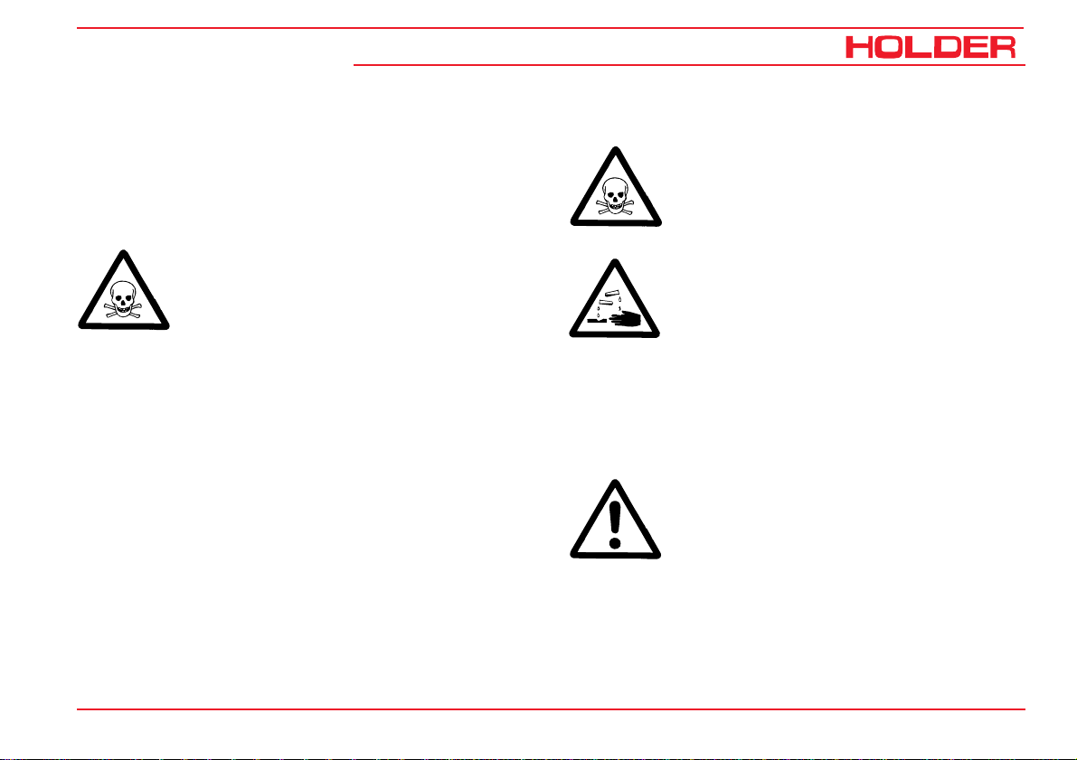
Safety Instructions for Handling Fuels and
Oils
Gear Oil, Engine Oil, Diesel Fuel
Do not eat, drink or smoke when handling
these fuels and oils. Prolonged intensive contact may cause degreasing and irritation of
the skin. Wash skin with soap and water, use
skin care products. If necessary, wear protective gear. Change soaked clothes and
shoes immediately. If vapour or mist was inhaled, breathe fresh air. Consult a doctor if
the complaint persists. After contact with the
eyes, rinse the eyes thoroughly with water
(at least 10 minutes), then consult an eye
doctor. If swallowed, do not force to vomit,
but consult a doctor. Danger of slipping on
the spilled product, particularly in connection
with water.
Oils can contaminate water. Always keep
them in approved containers. Avoid spilling
oils. Remove spilled fluids immediately with
an oil binding agent and discard in accordance with laws and regulations. Discard
drained fluids as specified.
12 145 146
Page 15
A 5.58 / A 5.58 P
Observe applicable laws and regulations. Oils
are inflammable. Do not let them come in
contact with hot engine parts as fire can result.
Hydraulic Oil, Brake Fluid
During tractor operation, these fluids are pressurised and pose a health hazard. Do not spill
these fluids. Remove any spilled fluids immediately with oil binding agent and discard them
as specified. Discard old fluids as
specified.Observe applicable laws and regulations. Do not allow them to come in contact
with hot engine parts. Danger of fire!
Avoid contact with the skin. Avoid the inhalation of spray fog. The penetration of pressurised fluids into the skin is particularly dangerous if these fluids are under high pressure and
escape from the hydraulic system through
leaks. Seek medical aid at once in case of such
injuries.
If injuries can not be excluded, use suitable
personal protector (for example, protective
gloves, glasses and skin protection and skin
care creams).
Operating Instructions
Information on Operation
Battery Acid
Battery acid contains dissolved sulphuric
acid. This acid is poisonous and caustic. When
working with battery acid, always wear protective clothing and eye protectors. Do not
allow acid to contact the clothing, skin or eyes;
in case of contact wash immediately with
ample clean water. In case of personal injuries, consult a doctor at once. Neutralise
spilled battery acid immediately.
Discard old fluids as specified. Observe applicable laws and regulations.
Emissions
Exhaust Gases
During operation, the engine emits exhaust
gas into the environment. The exhaust gas
mainly consists of water vapour, carbon dioxide (CO2), carbon monoxide (CO), hydrocarbon (CH), nitrogen oxide (NOX) and soot.
The components CO, CH and NOX are poisonous or hazardous to health and should
not be inhaled in high concentrations. Soot is
a carcinogenic material.
145 146 13
Page 16

Operating Instructions
Information on Operation
Particularly the particles contained in the
exhaust gas can cause cancer.For this reason the engine should not be operated in enclosed spaces.
Heat
The exhaust gases are very hot and can ignite inflammable material. The exhaust gas
pipe should therefore be kept away from ignitable material.
Battery
During charging, the battery produces a mixture of oxygen and hydrocarbon (detonating
gas). This mixture of gases is explosive and
may not be ignited. The risk of explosion can
be avoided with proper ventilation and keeping naked flames away. Observe the safety
rules when handling the battery. Observe the
safety rules when handling the battery.
A 5.58 / A 5.58 P
14 145 146
Page 17

Operating Instructions
A 5.58 / A 5.58 P
Technical Data
Model Variants
ledoMnoissimsnarTelxafoepyTenignEfoepyTtuptuOenignE
85.5carT-A
85.5carT-A
P85.5carT-A
P85.5carT-A
145 146 15
xobraeg
xobraeg
xobraeg
xobraeg
gnisreverlacinahceM
gnisreverlacinahceM
gnisreverlacinahceM
gnisreverlacinahceM
elxadradnatSF1101L3FB)PH4.45(Wk04
elxadradnatSF1102L3FB)PH85(Wk34
elxatesffOF1101L3FB)PH4.45(Wk04
elxatesffOF1102L3FB)PH85(Wk34
Page 18
Operating Instructions
Technical Data
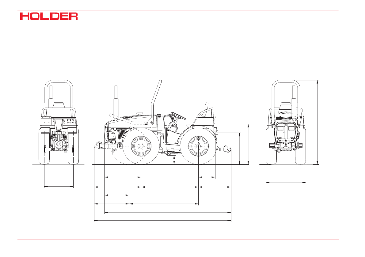
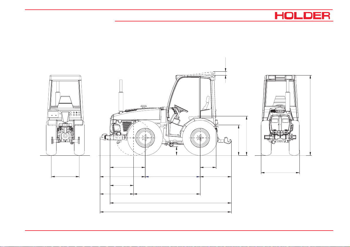
Tractor Dimensions with Safety Loops
Dimensional Drawing
A 5.58 / A 5.58 P
a
b
d
c
928
e
Track width
16 145 146
1190
624
Wheelbase 1448
Wheelbase 1752886
3198
3460
422
822
f
Page 19
A 5.58 / A 5.58 P
Tractor Dimensions with Cabin
Dimensional Drawing
Operating Instructions
100
b
d
c
Technical Data
a
928
e
Track width
145 146 17
1190
624
Wheelbase 1448
Wheelbase 1752886
3198
3460
422
822
f
Page 20

Technical Data
Table of Dimensions
Operating Instructions
A 5.58 / A 5.58 P
hctiHreliarT
seryTepyT
TPM81-5.01
81R08/572
TPM81-05.771-131439020502959802895817
81R07/0821-13-22419028402759602695617
81R56/0234-13-22420129502869712706727
5.51-06/00449021502069902995917
5.71-06/05311-131419028402759602695617
51R05.11x131-13-30226029102829771765786
51-05.51x138-131494026002519461455476
51-05.21x3391-131498026402559402495417
51-05.51x3381-131418028302749691685607
22-1314
3-13-224
41-1314
2-13-224
thgieHllarevO
revolloR
noitcetorP
a
mm
80125602479322316337
61123702289132126147
thgieHllarevO
nibaCfo
a
mm
.mm021sesaercninibacfothgiehllarevoehtC/AhtiW
thgieH.gvA
taeSfo
b
mm
dnuorG
ecnaraelC
c
mm
noitisoPtsewoLnoitisoPtsehgiH
d
mm
d
mm
18 145 146
Page 21

A 5.58 / A 5.58 P
Track Widths A-Trac 5.58
Operating Instructions
Technical Data
gninruT.niM
seryT
TPM81-05.7
81R05.7
81-08/052m67.50478090998511058810100118621049801109118531
•STPM81-5.01
•S81R81/5.01
S81R08/572•m68.54674884401461147849945114721469480144214631
81R07/082m18.54674886401661147849965116721469480164216631
TPM81-5.01
81R08/5.01
81R08/572m78.541843949014111429449402142214101430149214131
81R56/023m09.541843852115411429449532155214101430152315431
51-05.21x33m98.541803842110411429049432105214101030142310431
5.71-06/053m79.5-448- 4911-459- 4031-4401- 4931
5.71-55/004m99.5-----459- 4331-4401- 4241
51R05.21x33m79.5-468- 702109847933217131089460132317041
51-05.11x13
51R05.11x13
51-05.51x13
51-05.51x33
5,51-06/004m70.6-409- 4031-4101- 4141449401144314051
1.61xLL61/33m21.6-729- 4531-7301- 4641-7211- 4551
htiwsuidaR
htdiW
kcarTtsellams
.nim
mm
m76.5107*149109*1411118150111011521109141110111431
m18.54674888301851147849984118621469480183218531
m68.541843888018011429449891181214101430188218031
m49.5-078- 881148808920218921479070129218831
m60.6-409- 9921-4101- 9041249401173319941
)418eziS
ehtdiWkcarTfhtdiWllarevOehtdiWkcarTfhtdiWllarevOehtdiWkcarTfhtdiWllarevO
.xam
mm
mm
.enibacdesolcneyllufdnalaitraphtiwelbissoptoN*
egnalF(htdiWkcarTlamroN
mm55=275epyTmm001=3-2905epyT
.nim
.xam
.nim
.xam
mm
mm
mm
.ylthgillluhtcatnocnacserytesehtnoitallicsodnakcolgnireets.xamhtiW•
.nim
mm
.xam
mm
srecapSbuHhtiW
.nim
mm
.xam
mm
.nim
mm
.xam
mm
145 146 19
Page 22

Operating Instructions
Technical Data
Track Widths A-Trac 5.58 P
A 5.58 / A 5.58 P
otsuidaRgninruT.niM
taderusaem(0207NID
seryT
m
5.7TPM81-0
81R05.7
81-08/052058htdiwkcart.fm37.6058810100118621069821101218731
STPM81-5.01
81R81/5.01S
S81R08/572478htdiwkcart.fm97.647849945114721489401146214831
81R07/082478htdiwkcart.fm87.647849965116721489401166216831
TPM81-5.01
81R08/5.01
57281R08/429htdiwkcart.fm48.6429449140242214301450141314331
81R56/023429htdiwkcart.fm78.6429449532155214301450154315631
51-05.21x33429htdiwkcart.fm68.6429049432105214301050144310631
5.71-06/053459htdiwkcart.fm39.6-459- 4031-4601- 4141
5.71-55/004459htdiwkcart.fm69.6-459- 4331-4601- 4441
51R05.21x33479htdiwkcart.fm49.6-479- 71310001480134317241
51-05.11x13
51R05.11x13
51-05.51x13
51-05.51x33
5.51-06/0044101htdiwkcart.fm40.7-4101- 4141-4211- 4251
1.61xLL61/337301htdiwkcart.fm90.7-7301- 4641-7411- 4751
fotnioptsomretuo
)elcihev
mm
118htdiwkcart.fm46.6118115011101521129161112111631
478htdiwkcart.fm87.647849984118621489401185218731
429htdiwkcart.fm87.6429449189181214301450180318231
089htdiwkcart.fm19.6-089- 8921499090121318041
4101htdiwkcart.fm30.7-4101- 9041-4211- 9151
ehtdiWkcarTfhtdiWllarevOehtdiWkcarTfhtdiWllarevO
.nim
.xam
mm
htdiWkcarTlamroN
)429ezisegnalf(
).dtsraertabuhmm55(
.nim
mm
.xam
.nim
.xam
mm
mm
mm
.nim
mm
srecapSbuHhtiW
raeRtamm001=3-2905epyT
tnorFtamm55=3-275epyT
.xam
mm
20 145 146
Page 23

A 5.58 / A 5.58 P
Weights
Operating Instructions
Technical Data
srotcarTllAgknithgieW
thgiewlatotelbissimreP
elxatnorfnodaolelbissimreP
elxaraernodaolelbissimreP
hctihreliartnodaolgnitroppuselbissimreP
10,5-18 MPT
Tyres
Empty weight ATrac 5.58,
wheelbase 1448
mm (incl. driver 75
kg)
Total: kg 1810 1840 1830 1856 1850 1876 1866 1892 1825 1852 1775 1804 1750 1776
Front: kg 1085 1050 1095 1058 1105 1068 1113 1076 1092 1056 1067 1032 1055 1018
Rear: kg 725 790 735 798 745 808 753 816 733 796 708 772 695 758
On A-Trac 5.58 the empty weights are increased by 140 kg, at the rear increased by 195 kg and at front reduced by 55 kg
350/60-17.5
With
rollover
protection
With 6point
safety
frame
(partial
cab)
275/80 R18 280/70 R18 320/65 R18
With
rollover
protection
With 6point
safety
frame
(partial
cab)
With
rollover
protection
gk0082
gk0071
gk0071
gk006
With 6point
safety
frame
(partial
cab)
With
rollover
protection
tfiltnorF
With 6point
safety
frame
(partial
cab)
seilbmessA/yrailixuAlatoTtnorFraeR
raegdeepspeerC
gk31gk3gk01
gk76gk29gk52-
gk76gk25gk51
gk011
gk061
31x15,50-15
33x15,50-15
With
rollover
protection
With 6point
safety
frame
(partial
cab)
nibac.lcneyllaitraP
nibac.lcneylluF
33/16LLx16.1
400/55-17,5
400/60-15,5
With
rollover
protection
ekarbycnegremeepolS
With 6point
safety
frame
(partial
cab)
7.50-18
33x12,50-15
With
rollover
protection
With 6point
safety
frame
(partial
cab)
145 146 21
Page 24

Technical Data
Tyres
eryTfoepyTyticapaCdaoLeliforPebuT)rabni(erusserPriAsthgieWleehW
Operating Instructions
A 5.58 / A 5.58 P
ytpmE
thgieW
81R05.78A201eliforptaelCsey0.10.31-4314gk24.xorppa
81-08/052RP8eliforptaelCsey1.12.21-4314gk24.xorppa
TPM81-08/5.018A131/6A831eliforptaelCsey0.10.21-4314gk24.xorppa
81R08/572B031/2A241eliforptaelCsey0.10.11-4314gk24.xorppa
81R07/082B111/8A411eliforptaelCon6.02.11-4314gk24.xorppa
81R56/023B601/8A901eliforptaelCon5.01.11-4314gk24.xorppa
5.71-06/0535A501eliforptaelCsey4.01.12-4314gk34.xorppa
5.51-06/004RP8nwaLon5
51R05.11x13Q011daor-ffOon7.09.12-4314gk34.xorppa
51-05.51x133A901nwaLon7.07.1
51-05.51x33RP6arreTon4.00.12-4314gk34.xorppa
51-05.21x33RP6nwaLon5.05.12-4314gk34.xorppa
.00
.xaM
daoL
.12
epyTthgieW
14gk34.xorppa
-43
-4314gk34.xorppa
2
22 145 146
Page 25

A 5.58 / A 5.58 P
Engine Specifications
Operating Instructions
Technical Data
85.5A
P85.5A
rerutcafunaMGAztueDGAztueD
epyTobruTF1101L3FBobruT1102L3FB
noitarepofoedoMleseiDekorts-ruoFleseiDekorts-ruoF
srednilycforebmuN33
yticapaccibuCcc5812cc2332
noitpmusnocleuFmpr0402tah-Wk/g322mpr0402tah-WK/g612
deepsdetaRmpr0562mpr0062
deepsgnildimumixaMmpr0572mpr0572
deepsgnildimuminiMmpr009mpr009
mpr0562=ntarewoP)PH4.45(Wk04)PH85(Wk34
85.5A
P85.5A
145 146 23
Page 26

Operating Instructions
Technical Data
Theoretical Driving Speeds (km/h)
A 5.58 / A 5.58 P
RPM 2650
275/80 R18
Group
Gear
Total Ratio Forwards
0.431 0.423 0.417 0.414 0.409 0.408 0.406 0.406 0.404 0.396 0.377 0.364 m
F 4 13.2 32.6 32.0 31.5 31.3 30.9 30.9 30.7 30.7 30.6 30.0 28.5 27.5 km/h
F 3 20.4 21.1 20.7 20.4 20.3 20.0 20.0 19.9 19.9 19.8 19.4 18.5 17.8 km/h
F 2 33.9 12.7 12.5 12.3 12.2 12.0 12.0 12.0 12.0 11.9 11.7 11.1 10.7 km/h
Max. Speed
F 1 61.5 7.0 6.9 6.8 6.7 6.6 6.6 6.6 6.6 6.6 6.4 6.1 5.9 km/h
M 4 15.8 27.2 26.7 26.4 26.2 25.8 25.8 25.7 25.7 25.5 25.0 23.8 23.0 km/h
M 3 24.4 17.6 17.3 17.1 16.9 16.7 16.7 16.6 16.6 16.5 16.2 15.4 14.9 km/h
M 2 40.6 10.6 10.4 10.3 10.2 10.1 10.0 10.0 10.0 9.9 9.7 9.3 9.0 km/h
M 1 73.8 5.8 5.7 5.6 5.6 5.5 5.5 5.5 5.5 5.5 5.4 5.1 4.9 km/h
S 4 55.6 7.7 7.6 7.5 7.4 7.3 7.3 7.3 7.3 7.3 7.1 6.8 6.5 km/h
S 3 86 5.0 4.9 4.8 4.8 4.7 4.7 4.7 4.7 4.7 4.6 4.4 4.2 km/h
S 2 143.1 3.0 3.0 2.9 2.9 2.9 2.8 2.8 2.8 2.8 2.8 2.6 2.5 km/h
S 1 259.6 1.7 1.6 1.6 1.6 1.6 1.6 1.6 1.6 1.6 1.5 1.5 1.4 km/h
10.5-18 MPT
320/65 R18
250/80-18
400/60-15.5
7.50-18 MPT
350/60-17.5
280/70 R18
33x12.50-15
33x15.50-15
31x11.50 R15
31x15.50-15
Type
421
422
24 145 146
Page 27

A 5.58 / A 5.58 P
Technical Data /Filling Quantities
ylbmessAnoitamrofnI.lppuSnoitpircseD
Operating Instructions
Technical Data
ebeirteG
sffo-ekatrewoP
tnorf,MPR- mprenigne0632tampr0001
raer,MPR- mprenigne0252tampr057&mprenigne0542tampr045
eliforptfahsegdeW-1169NID)6(""8/31
hctulcOTPhctulc-ksid-elpitlumteW
kcollaitnereffiD ylsuoinatlumisdegagneebnacraerdnatnorF
metsysleuF
knatleuFleufleseiDsertil15
145 146 25
lacinahceM
xobraeggnisrever
tfahsfodne
selxayratenalphtiwsraegesrever21/sraegdrawrof21
tagnikoolnehwesiwkcolc:noitceridgnitator)raerdnatnorf(sOTP2
Page 28

Operating Instructions
Technical Data
ylbmessAnoitamrofnI.lppuSnoitpircseD
gnireetS
ekaM- smargnireetsgnitca-elbuod2htiwcitatsordyH
evlavgnireetS-SL521CPSOlortibrO
sekarB
ekarbecivreS- sleehw4llanognitca,raertasekarbmurdxelpmiS
noitavitcA-lacinahceM
ekarbgnikraP- sleehw4llanognitca,raertasekarbmurdxelpmiS
noitavitcA-lacinahceM
hctihreliarT
ekaM- gnitatordnaelbatsujda-thgieh,rellümrahcS
tfilraeR
epyT- elbatsujdaknilreppu,dradnatstniop-3REDLOH
A 5.58 / A 5.58 P
gnitnuoM-IyrogetaC
rewopgnitfiL- ))stniopnoitallatsnitaderusaem(N00081
skcaJ-skcajgnitca-elgnis2
26 145 146
Page 29

A 5.58 / A 5.58 P
ylbmessAnoitamrofnI.lppuSnoitpircseD
tfiltnorF
ekaM- elbatsujdaknilreppu,dradnatstniop-3REDLOH
gnitnuoM-IyrogetaC
rewopgnitfiL-N0007
kcaJ-kcajgnitca-elbuod1
sciluardyhecivreS
pmuPdnartsdnuS
yticapacyrevileD- )deepsenignempr052tanim/L53(cc41
erusserpgnitarepO-rab091-081
knatliociluardyHL81
metsyslacirtcelE
egatlovgnitarepO-CDV21
Operating Instructions
Technical Data
yrettaB-hA88/V21
rotanretlA-A06/V21
retratS-Wk2,2/V21
145 146 27
Page 30

Operating Instructions
Technical Data
Noise Level
The tractor emits the following noise level (measured at the
driver’s ear) according to EC Standard 77/311/EEC; measurement according to Appendix II).
Table of Noise Levels and Absorption Rating
A 5.58 / A 5.58 P
ledoMepyTenignEtuptuOenignE)A(BdleveLesioN
yllaitrapnibaC
emarFytefaS
stniop6dna2*nepodesolc*nepodesolc
85.5AF1101L3FB)PH4.45(Wk0488887808082.2
P85.5AF1101L3FB)PH4.45(Wk0488887808082.2
85.5A1102L3FB)PH85(Wk3498987838087.1
P85.5A1102L3FB)PH85(Wk3498987838087.1
nepotnevfoordnaneercsdniwtnorF*
Exhaust Gas Identification
The absorption rating is stated on the identification plate.
28 145 146
desolcne
yllufnibaC
desolcne
etar
noitprosbA
Page 31

A 5.58 / A 5.58 P
Description
Views of Tractor
Front Right View
1 Windshield wiper
reservoir
2 Driver’s cab
3 Headlight, top
4 Turn signal, clearance
light
5 Wiper/washer
6 Fuel tank
filler neck
7 Intake for
air filter
8 Hydraulic coupling for
implement
9 Headlight, bottom
10 Hydraulic coupling for
implement
11 Access cover for
engine oil check
12 Front axle
13 Rear axle
Operating Instructions
1
2
3
4
5
6
7
8
9
10
11
13
145 146 29
12
Page 32

Description
Tractor
Rear Right View
1 Front axle
2 Rear axle
3 Hydraulic coupling for
implement
4 Rope release for rear
lift
5 Rear lift - lower link
support
6 Upper link
7 Back-up light
8 Stop and turn signal
light
9 Socket for trailer
lighting
10 Hydraulic coupling for
implement
11 License plate light
12 Support for rotating
beacon
Operating Instructions
A 5.58 / A 5.58 P
12
11
10
9
8
7
6
30 145 146
4 3 2
5
1
Page 33

A 5.58 / A 5.58 P
Driver’s Station
Operating Controls
Operating Instructions
Description
1 Control lever for powershift multiple-disk clutch
2 Engine speed adjustment knob
3 Hydraulic oil temperature gauge
4 Steering wheel
5 Multi-function display
6 Vehicle fuses
7 Power socket
8 Preheat/starter switch
9 Circulating oil switch 2nd flow regulator
10 Directional indicator
11 Multi-function lever with forward/reverse selector
lever
12 Gearshift lever
13 Accelerator pedal
14 Brake pedal
15 Steering column height adjuster
16 Clutch pedal
145 146 31
17 Range selector lever
18 Steering column tilt adjuster
19 Turn signal lever
20 Fan switch
21 Hazard warning flasher switch
22 Differential lock switch
23 Light switch
Page 34

Description
Operating Instructions
A 5.58 / A 5.58 P
23
22
21
20
19
1
2
3
4
5
6
7
8
9
10
11
12
18
32 145 146
17
16
15
14
13
Page 35

A 5.58 / A 5.58 P
Operating Controls for Attachments*
1 Multi-function lever functions plate
2 Multi-function lever
3 Rear lift control lever
4 Rear lift lock knob
5 Lock knob for multi-function lever right/left
6 Lock knob for multi-function lever forward/backward
7 Control lever for flow regulator 1st circuit*
8 Sliding sleeve for locking flow regulator 1st circuit*
9 Adjustment knob for flow regulator 1st circuit*
Operating Instructions
2 3 4
1
Description
5
6
7
Bild_005
7
8
9
* Option
145 146 33
Bild_004
Page 36

Operating Instructions
Description
Multi-function lever
1 Forward direction arrow (illuminated if selected)
2 Reverse direction arrow (illuminated if selected)
3 Forward/reverse selector lever
(left forward – right reverse)
4 Multi-function lever
5 Function button*
6 Hydraulic control**
Multi-function lever forward/back
7 Hydraulic control**
Multi-function lever left/right
8 Hydraulic control**
Multi-function lever left/right
together with function button (5)
2 3
1
8
A 5.58 / A 5.58 P
4
5
6
Bild_006
* Option
** Observe the colour symbols
34 145 146
7
Bild_007
Page 37

A 5.58 / A 5.58 P
8
Pedals
1 Brake pedal
2 Accelerator pedal
3 Clutch pedal
Operating Instructions
3
Description
1
2
Bild_00
Heating*
1 Notice label
- down = warmer
- up = cooler
2 Heating slide valve
3 Air outlet
* Option
145 146 35
3
2
1
Bild_009
Page 38

Description
0
Front PTO Selector
1 Label for PTO rpm
- Top position (ON) 1000 rpm
- lower position (OFF)
2 PTO selector lever
Rear PTO Selector
1 PTO selector knob
- Front position (IN) 540 rpm
- Centre position (OUT)
- rear position (IN) 750 rpm
Operating Instructions
A 5.58 / A 5.58 P
12
Bild_01
1
36 145 146
Bild_011
Page 39

A 5.58 / A 5.58 P
Multi-function Display, Legend
Operating Instructions
Description
15 16 1 2 3
1 Fuel gauge
2 Engine oil temperature
gauge
3 Tachometer with mark-
ings for PTO rpm
4 Hour meter
5 Digital speedometer
6 Turn signal indicator
7 Turn signal indicator 2nd
trailer
8 Turn signal indicator 1st
trailer
9 High beam
10 Dip beam
11 Engine oil temperature
12 Preheating indicator
13 Engine oil pressure
warning light
14 Battery charging indicator
15 Parking brake
16 Differential lock
14
13
12
11
15
Motor
10
FRONT
1000U/min
540U/min
5
1
2
6
Km/h
digital system
5
0
RPMx100
PTO
electronic
00000 00 h
750U/min
478910
20
25
30
Bild_012
145 146 37
Page 40

Operating Instructions
Description
Controls for Mechanical Gearbox
1 Gearshift lever (right looking forward)
with 4 synchronised gears 1-2-3-4
2 Range selector lever (left looking forward)
with 3 speed ranges:
S – Highway driving
M – Medium speed
L - Slow speed
3 Gearshift label
A 5.58 / A 5.58 P
1
2
Bild_013
2 1
1
2
3
4
5
6
7
8
9
3
10
11
12
L
1
L
2
L
3
L
4
M
1
S
1
M
2
S
2
M
3
S
3
M
4
S
4
MSL
4
2
31
Bild_014
38 145 146
Page 41

A 5.58 / A 5.58 P
Controls on Top Cabin
1 Front wiper/washer switch
2 Rotating beacon switch
3 Top headlights
4 Air vent nozzle* for air conditioner
5 Cold air rotary switch* for air conditioner
6 Blower range rotary switch* for air conditioner
7 Radio*
8 Loudspeaker*
9 Cab fuses
Operating Instructions
Description
3 4 5 4 6 4
2
7
1
9
* Option
145 146 39
8
Bild_016
Page 42

Operating Instructions
Description
Slope Emergency Brake Lever*
1 Emergency brake lever
2 Pressure gauge
3 Notice label
4 Brake ram
A 5.58 / A 5.58 P
1 2
Bild_017
3
* Option
40 145 146
Bild_143
4
Page 43

A 5.58 / A 5.58 P
Location of Plates and
Labels
Identification Plates
Operating Instructions
Description
1 Engine type plate
2 Chassis serial number
3 Machine type plate
4 Cabin type plate
4
1
3
2
Bild_022
145 146 41
Page 44

Operating Instructions
Description
Mounting Instructions for License Plate
- Attach the front license plate on the mounting plate
(1).
A 5.58 / A 5.58 P
1
- Attach the rear license plate at the rear (2) above the
left tail light.
2
42 145 146
Bild_023
Bild_024
Page 45

A 5.58 / A 5.58 P
Overview of Options and Variants
Operating Instructions
Description
ylbmessAnoitamrofnI.lppuS
retliflaocrahCnoitalitnevnibacroF47-43-224
thgilgnikrowraeR 88-4325
tfiltnorF85.5AroF1-15-124
tfiltnorFselxatesffo85.5AroF1-15-224
tnemelegnitaehliO)CAV032(C°02-morf96-4325
C/AdetargetnI 97-43-224
reveldnahhtiwxobraegdeepspeerC 11-2625
noisnetxeOTP 1-26-224
tiucricts1redividwolF 5-08-224
pmuP-pmupdradnatS
yticapacyrevileD- .ver/cc41
etarwolF- nim/L52-0
erusserpmumixaM- rab002
/noisnemiD
epyT/.oNredrO
145 146 43
Page 46

Description
Operating Instructions
A 5.58 / A 5.58 P
ylbmessAnoitamrofnI.lppuS
tiucricts1redividwolF 51-08-224ro51-08-124
pmuP-pmupmednaT
yticapacyrevileD- .ver/cc11
etarwolF- nim/L52-0
erusserpmumixaM- rab002
raer2/6kcolbnoitubirtsid.rtcelE 01-08-224
tnorf2/6kcolbnoitubirtsid.rtcelE 11-08-224
tnorf3/8kcolbnoitubirtsid.rtcelE 21-08-224
/noisnemiD
epyT/.oNredrO
44 145 146
Page 47

A 5.58 / A 5.58 P
Accessories
The tractor is delivered with the following accessories:
1 Operating manual
2 Bio-pass for certification of filling
environment-friendly hydraulic oil
3 Key holder
4 2 ignition keys
5 4 door keys
6 Upper link with retaining pins
7 Bowden cable for catch hook
Operating Instructions
1
3
Description
2
4
5
6
7
145 146 45
Page 48

Page 49

Operating Instructions
A 5.58 / A 5.58 P
Taking into Service
Daily Checks and Activities prior to Taking
into Service
If damage or defects are found during the following checks,
they must be eliminated before taking the vehicle into service. Do not operate the tractor before proper repairs are carried out. Safety and protective devices should not be removed or disabled. Fixed specified settings may not be
changed.
Before starting work, make yourself familiar with all the functions and protective devices of the tractor.
Checking or Cleaning the Cooler and Radiator Protection Screen
NOTE
- Check if the mud guards (1 and 3) are
clean.
- Clean the mud guards if necessary.
- The air intake of the air filter (2) must be
clean.
23
1
Bild_025
145 146 47
Page 50

Operating Instructions
Taking into Service
Checking the Engine Oil Level
NOTE
Check the engine oil level only when the tractor is on level ground.
- Let the engine approx. 2 minutes with the heat shut-off
valve open:
- Turn off the engine and open the access cover on the
right-hand side of the tractor. Pull the oil dipstick (1)
out after approx. 1 minute.
- The oil level must be between the Min (3) and Max (2)
marking.
- Top up oil as specified in the maintenance manual.
A 5.58 / A 5.58 P
1
Bild_026
ATTENTION
Do not fill too much oil.
48 145 146
2
3
Bild_027
Page 51

Operating Instructions
A 5.58 / A 5.58 P
Checking the Trailer Hitch (optional), if required
- Check the trailer hitch for proper condition and opera-
tion. Carry out the check according to the instructions
in the section "Operating the Trailer Hitch".
Checking Tyre Inflation Pressure
NOTE
Your tractor can be equipped with different types
of tyres. The specified inflation pressure for your
tyres is given in the table entitled "Tyres" in the
technical data section.
- Check the inflation pressure on all four tyres. All tyres
must have the same pressure. If the pressure is too
low, the rolling resistance increases. This causes an
increase in fuel consumption and tyre wear, the
driving characteristics become poorer.
DANGER
If the inflation pressure is too high, the tyres
can explode.
Taking into Service
Bild_028
- The tyres should not be damaged or worn.
- Have damaged tyres replaced without delay. Due to the
longer braking distance the risk of an accident is increased.
Bild_029
145 146 49
Page 52

Operating Instructions
Taking into Service
Checking the Implement Hydraulics Oil Level
- Retract all hydraulic cylinders.
- Check the oil level at the sight glass (1).
The oil level must be at the centre of the sight glass.
- Top up oil as specified in the maintenance manual.
A 5.58 / A 5.58 P
1
Bild_030
50 145 146
Page 53

A 5.58 / A 5.58 P
Filling Fuel
- If necessary, read the fuel level (1) on the multi-
function display.
CAUTION
Danger of fire when handling fuels. Turn off
the engine. Do not fill any fuels in the vicinity
of naked flames, ignition sparks or hot engine parts. Do not smoke during refuelling.
- Remove the fuel tank filler cap (2).
- Top up Diesel fuel as specified in the maintenance
manual.
Operating Instructions
Taking into Service
1
Motor
1
2
Km/h
digital system
15
10
FRONT
5
0
RPMx100
PTO
electronic
0000000 h
1000U/min
540U/min
750U/min
20
25
30
Bild_031
Filling quantity ............................................ approx. 51 L
2
- Refit the filler cap (2).
Bild_032
145 146 51
Page 54

Operating Instructions
Taking into Service
Checking the Clutch Fluid Level
- Check the level at the clutch fluid reservoir (1).
- The fluid level must between the Min and Max marking at the reservoir.
- Top up brake fluid as specified in the maintenance
manual.
Adjusting the Steering Wheel
NOTE
The tilt of the steering wheel can be set to a
comfortable position.
DANGER
Do not adjust the steering wheel while driving.
- Loosen the lever (2).
- Adjust the tilt of the steering wheel.
- Retighten the lever (2).
- Loosen the lever (1).
- Adjust the height of the steering wheel.
- Retighten the lever (1).
A 5.58 / A 5.58 P
1
Bild_033
1
52 145 146
2
Bild_034
Page 55

A 5.58 / A 5.58 P
5
Adjusting the Driver’s Seat with Mechanical Suspension
DANGER
Do not adjust the seat while driving. Risk of
accidents!
1 Horizontal adjustment
- Raise the handle (1) and push the seat to the front
or rear.
- Release the handle and allow the seat lock to
engage.
2 Weight adjustment
- Adjust the desired driver’s weight by turning the
weight adjustment lever (2).
- If the adjustment is correct, the position set at the
height adjustment handle (4) is indicated in the
window (3).
3 Height adjustment
- Three different heights can be set with the star
knob (4).
- The weight should be adjusted after each height
adjustment.
Operating Instructions
Taking into Service
1
NOTE
To prevent damage to your health, the individual adjustment should be checked and
adjusted before taking the vehicle into service.
2
43
Bild_03
145 146 53
Page 56

Operating Instructions
Taking into Service
Adjusting the Driver’s Seat with Pneumatic Suspension*
A 5.58 / A 5.58 P
DANGER
Do not adjust the seat while driving. Risk of
accidents!
1 Horizontal adjustment
- Raise the handle (1) and push the seat to the front
or rear.
- Release the handle and allow the seat lock to
engage.
2 Weight adjustment
- Select the desired driver’s weight by pushing or
pulling the adjustment knob (2).
- A green field appears in the window (3) if the
setting is correct.
3 Height adjustment
- Put the seat to the desired height by pushing or
pulling the adjustment knob (2).
- The marking in the window (3) must be green.
* Option
1
3 2
DANGER
To prevent damage, operate the compressor
for 1 minute maximum.
NOTE
To prevent damage to your health, the individual adjustment should be checked and
adjusted before taking the vehicle into service.
Bild_036
54 145 146
Page 57

Operating Instructions
A 5.58 / A 5.58 P
Filling Washing Water
NOTE
The washing water reservoir for the windshield
washer is located behind the driver’s seat.
- Open the filler cap (1) and top up washing water in the
reservoir.
Filling capacity.......................................... approx. 1.3 L
Checking the Lights and Rear View Mirror
- Check the lighting for proper operation. Carry out the
check according to the instructions in the section
entitled "Lights".
- Adjust the rear view mirror so that the roadway behind
the tractor and the working area are easily seen.
Taking into Service
1
Bild_037
Bild_038
145 146 55
Page 58

Operating Instructions
Taking into Service
A 5.58 / A 5.58 P
Starting the Engine
Instructions before Starting the Engine
DANGER
Do not start or run the engine in enclosed
spaces. Danger of poisoning through exhaust
gases!
Instructions for Starting
CAUTION
Before starting, make sure no one is in the
vicinity of the vehicle.
ATTENTION
Do not use a starting aid such as Startpilot
or similar means. Turn off the drive or driven
implements.
CAUTION
Start the engine only from the driver’s station.
56 145 146
Page 59

A 5.58 / A 5.58 P
Starting the Engine
- Shift the gearshift lever (4) to neutral.
- Set the forward/reverse selector switch (3) to the
neutral position (centre).
- Fully depress the clutch pedal (5).
NOTE
The engine can only be started if the pedal is
fully depressed (starting safety switch).
- Set the hand throttle (1) to idle (push in fully).
- Insert the ignition key and turn the preheat/starter
switch (2) to position 1.
Operating Instructions
Taking into Service
1
5
2
3
4
Bild_039
145 146 57
Page 60

Operating Instructions
Taking into Service
NOTE
The battery charging indicator (8), the engine
oil pressure indicator (7) and parking brake indicator (9) (if parking brake is engaged) come
on.
- Turn the ignition key to position 2.
The engine is being preheated. The preheating indicator
(6) comes on.
NOTE
When starting at low temperatures, hold the
ignition key longer (approx. 1 minute) in position 2.
- When the preheating indicator extinguishes, turn the
ignition key to position 3 to start the engine.
ATTENTION
Operate the starter for a maximum of 20 seconds. Wait one minute, then repeat the starting procedure. Repeat the starting procedure
only twice at most. In case the engine does
not start, carry out a troubleshooting according to the section entitled "Problems, Causes,
Remedy".
6 7
A 5.58 / A 5.58 P
9
8
15
Motor
1
2
Km/h
digital system
NOTE
The ignition lock has a starter safeguard lock.
The ignition key must be switched back to
position 0 before it can be turned from position 1 to position 2 or 3 again.
10
FRONT
1000U/min
5
0
540U/min
RPMx100
PTO
electronic
0000000 h
20
25
750U/min
30
Bild_040
58 145 146
Page 61

A 5.58 / A 5.58 P
- Release the ignition key after the start.
The battery charging indicator (2) and the engine oil
pressure indicator (1) extinguish.
- Set the engine speed with the hand throttle (5) or
accelerator pedal (6) to the desired RPM (3).
- The hour meter (4) is activated.
Operating Instructions
Taking into Service
1 2 3 4
Motor
1
2
Km/h
digital system
15
10
FRONT
5
0
1000U/min
540U/min
RPMx100
PTO
electronic
0000000 h
20
25
750U/min
30
Bild_041
Checking Brakes and Steering for Proper Function
5
- Make a short trial run and check the steering and
brakes for proper operation.
DANGER
6
Do not drive a tractor with a defective steering and/or braking system.
Bild_042
145 146 59
Page 62

Operating Instructions
A 5.58 / A 5.58 P
60 145 146
Page 63

A 5.58 / A 5.58 P
Operation
Before Starting to Drive
Operating Instructions
When driving on public highways, observe the regulations
of the highway code.
Driving Safety Rules
• Drive the tractor only from the driver’s station with the
cab doors closed.
• Always adjust your speed to the driving conditions
and the load you are carrying.
• Never drive downhill without having the tractor in gear
or with the engine stopped.
• Before driving, check that no one is standing in the
immediate vicinity of the vehicle.
• The driving behaviour of the tractor is strongly affect-
ed by the weight and swing range of the implements,
trailers and, if fitted, ballasting. Therefore drive slowly
with heavy equipment and take the longer braking
distance into consideration.
145 146 61
• When following a curve with a trailer or other attachments, do not forget to take the added length and drag
into consideration.
DANGER
Any parts of the implements posing a traffic
hazard must be covered before driving or
identified with warning signs.
• Switch off the differential lock when travelling along a
curve.
• When driving on slopes, drive downhill if possible; if
you have to turn, turn only when driving uphill.
• On steep slopes you can improve traction by activating the differential lock.
• Drive across slopes only in accordance with the notes
at the end of this chapter.
Page 64

Operating Instructions
Operation
Driving with Mechanical Gearbox
A 5.58 / A 5.58 P
- Set the gearshift lever (2) to 0.
- Start the engine.
- Select the direction of travel with the forward/reverse
selector switch (1) (forward or reverse). The indicator
(3) is on green and flashing (forward or reverse).
- Fully depress the clutch pedal (4) (buzzer sounds
until shifting is completed). The indicator (3) is now
illuminated green continuously.
- Shift the gearshift lever (2) to the right (looking forward) into the desired gear.
Four gears 1-2-3-4 are available (2).
- Shift the range selector lever (5) to the left (looking
forward) to the desired speed range.
Three speed ranges are available (5):
S - Fast
M - Medium
L - Slow
2345
5 2
4
MSL
2
31
1
Bild_043
Bild_144
62 145 146
Page 65

A 5.58 / A 5.58 P
NOTE
The label (1) shows the possible shift combinations. You have a total of 12 gears available, both for forward and for reverse travel.
- Release the clutch pedal (3) to start driving.
ATTENTION
Do not keep the foot on the clutch pedal when
driving.
- Control the driving speed with the accelerator pedal
(2) or the hand throttle (4).
NOTE
The attainable driving speeds can be read in
the table in the technical data section.
ATTENTION
When downshifting, the driving speed must
be reduced to the low speed range. As the
transmission is synchronized, you do not
have to give gas when downshifting.
Operating Instructions
1
2
3
4
5
6
7
8
9
1
10
11
12
4
Operation
L
1
L
2
L
3
L
4
M
1
S
1
M
2
S
2
M
3
S
3
M
4
S
4
Bild_045
23
145 146 63
Bild_046
Page 66

Operating Instructions
7
Operation
Changing the Direction of Travel
ATTENTION
The direction of travel can be changed when
driving slowly.
- To change the driving direction from forward to reverse, the forward/reverse selector switch (1) must be
pushed to the right.
- The green indicator (2) is flashing and shows the
selected direction of travel.
- As soon as the clutch pedal is fully depressed, a
buzzer sounds until shifting is completed. Then the
green indicator (2) is on steadily.
- Release the clutch pedal to drive the tractor in reverse.
NOTE
When working, we recommend preselection
of the direction of travel while driving.
ATTENTION
If the clutch pedal is released before the shifting is completed, the mechanical gear shifts
into neutral (0). Both arrows are flashing (2
and 3).
- Depress the clutch pedal again.
The green indicator is on steadily, shifting is completed.
A 5.58 / A 5.58 P
3
1
2
Bild_04
64 145 146
Page 67

A 5.58 / A 5.58 P
Engaging the Differential Lock
NOTE
With the differential lock you can improve
traction on soft, slippery ground. The lock is
engaged when the engine speed is over 1000
rpm. You can keep the differential lock engaged steadily and also only briefly by
toggling the switch momentarily.
ATTENTION
The differential lock may only be used when
driving straight ahead.
Operating Instructions
Operation
1
Engaging the Differential Lock briefly
Bild_048
- Depress the differential lock switch (1) at the top and
hold it. The indicator (2) in the multi-function display
2
lights up red. An intermittent alert sounds at the same
time. The differentials of both axles are locked and
power is transferred to all 4 wheels equally.
Engaging the Differential Lock steadily
- Toggle the differential lock switch (1) down. The
differential lock remains engaged until the switch is
turned off again.
Disengaging the Differential Lock
- Release the differential lock switch (1) or switch it to
Motor
5
1
2
Km/h
digital system
15
10
FRONT
RPMx100
0
PTO
electronic
0000000 h
1000U/min
540U/min
750U/min
20
25
30
the middle position. The differentials are in operation
again. The indicator (2) in the multi-function display
goes out and the alert ceases.
145 146 65
Bild_049
Page 68

Operating Instructions
0
Operation
Steering
The articulated steering is operated hydraulically. The wheels
also stay in track in curves, so that implements are guided
without any lateral offset.
Steering
- Turn the steering wheel (2) in the desired direction.
The possible turning radii depend on the tyres and track
widths of your tractor. For exact information refer to the track
width table in the section "Technical Data".
Brakes
A 5.58 / A 5.58 P
12
Bild_05
The service brake is a drum brake in the rear axle. It is
actuated mechanically and acts on all four wheels. The parking brake is engaged mechanically with the parking brake
lever.
66 145 146
Operating the Service Brake
ATTENTION
The engine can stall if you brake too hard in
the mechanical gear.
- Depress the brake pedal (1).
If the mechanical gearbox is fitted, the clutch pedal must
also be operated.
Page 69

A 5.58 / A 5.58 P
Engaging the Parking Brake
ATTENTION
The parking brake is not intended to be used
for braking while driving.
- Pull the parking brake lever (1) up.
The parking brake is engaged, the red parking brake
indicator (2) in the multi-function display comes on.
Operating Instructions
Operation
Disengaging the Parking Brake
1
Bild_051
- Pull the parking brake lever (1) up slightly, turn it and
then press it down.
The parking brake is released, the parking brake
2
indicator extinguishes.
15
ATTENTION
An alert is sounded when driving with the
hand brake applied.
Motor
1
2
Km/h
digital system
10
FRONT
5
RPMx100
0
145 146 67
PTO
electronic
0000000 h
1000U/min
540U/min
750U/min
20
25
30
Bild_052
Page 70

Operating Instructions
Operation
Driving on Slopes
DANGER
Driving on slopes is dangerous as the tractor
can tip over if the centre of gravity exceeds
the tip-over limit on an extreme slope.
The following factors reduce the hazard:
- small or no load
- low ground speed
- low gradient
- low tyre inflation pressure
NOTE
The driving comfort and the traction of the
tractor can be improved by reducing the inflation pressure.
Hangaufwärts
upslope
Hangaufwärts
A 5.58 / A 5.58 P
upslope
- large track widths
- level, non-bumpy terrain
When turning on slopes we recommend the proceeding as
shown in the drawing on the right.
68 145 146
Bild_053
Page 71

A 5.58 / A 5.58 P
Special Operating Instructions
Operating the Precipice Emergency Brake
ATTENTION
After the installation of the precipice emergency brake, a safety inspection is required.
CAUTION
Before the first operation, familiarize yourself
with the use of the precipice emergency
brake. Carry out trial brakings on different
types of ground. On hard ground the extension foot (5) must be removed.
- Start the engine.
- Operate a hydraulic valve until the pressure at the
pressure gauge (2) rises and is in the green range
(160-190 bar).
- Now raise the emergency brake lever (1) to release
the lock.
Operating Instructions
1
2
Bild_096
4
5
145 146 69
3
Bild_149
Page 72

Operating Instructions
Special Operating Instructions
ATTENTION
On roads drive only with the emergency brake
lever locked. Do not allow anyone to stand
around where they might get hurt.
- Pull the emergency brake lever (1) down.
The brake tines (3) are lowered.
The service brake should be operated at the same
time.
ATTENTION
Due to the strong braking of the tractor, the
operator can slide from the seat.
NOTE
After the actuation of the precipice emergency brake in the area of use, a hydraulic
valve must be operated so that the full accumulator pressure is available for raising the
tool (emergency brake).
A 5.58 / A 5.58 P
1
Bild_150
- To raise the brake tines, set the emergency brake
lever (1) up and lock it.
Observe the notice label (4).
70 145 146
4
Bild_097
3
Page 73

Operating Instructions
A 5.58 / A 5.58 P
Stationary Operation
The tractor can be used for stationary operation, for example, to drive a water pump via the PTO shaft.
ATTENTION
Place the tractor on level ground in both directions.
- Remove the protective sleeve from the PTO shaft.
- Attach the stationary equipment to PTO shaft (2).
- Shift the gear and range selector lever in to the
neutral position.
- Apply the parking brake.
DANGER
Before switching on the PTO, make sure no
one is standing in the vicinity of the tractor
and the rotating PTO shaft.
Special Operating Instructions
1
2
Hydraulic Oil Flow for Stationary Operation
When the tractor is stationary, hydraulic oil is available, for
example, for the operation of a hydraulic dump (1).
Max. oil quantity available ...................................... 14 L
ATTENTION
Before starting to drive after stationary operation, first check if the hydrostatic steering is
working. Turn the steering wheel fully to the
right and left several times to release air from
the steering system.
Bild_054
145 146 71
Page 74

Operating Instructions
Special Operating Instructions
Adjusting the Track Width
You can widen the track width of the tractor by adding
spacers (1).
You have a choice of 3 different spacers.
DANGER
Observe the safety notes on safe parking and
jacking up for the wheel change in the maintenance manual.
- Remove the wheels. Turn the wheels inside out or
install the selected spacers.
ATTENTION
The spacers must be mounted on the front
and rear axle so that the same track width is
obtained.
A 5.58 / A 5.58 P
NOTE
The arrows on the tyres must show in the
forward direction of rotation.
- Re tighten the wheel nuts to the specified torque.
Torque to ............................................................ 215 Nm
1
72 145 146
Bild_055
Page 75

A 5.58 / A 5.58 P
Operating the Emergency Shift
NOTE
In the event of a failure of the servomotor or
the electronic control, it is possible to drive to
an authorized workshop with the emergency
shift.
- Turn off the engine.
- Apply the parking brake.
- Put the range selector lever and the gearshift lever in
neutral.
- Remove the right rear wheel.
- Remove the cover.
- Remove the safety wire (3).
- Carefully press the ball socket of the servomotor (2)
down until it is disconnected.
- Move the operating lever (1) to the desired position.
V = forwards or R = reverse.
- Refit the cover.
- Refit the wheel.
- Tighten the wheel nuts to a torque of 215 Nm.
- Start the engine and drive to the workshop.
Operating Instructions
Special Operating Instructions
V
3
1
R
2
Bild_056
145 146 73
Page 76

Operating Instructions
Special Operating Instructions
Operation in Winter
A 5.58 / A 5.58 P
Putting on Snow Chains
Preheating of Oil*
Before starting the engine at temperatures below - 20 °C,
turn on the heating element* for preheating the oil.
- Connect the preheating system plug to a 230 VAC
source.
Observe the information of the battery manufacturer.
Winter Diesel Fuel
Whenever temperatures fall below 0°C, use winter Diesel or
super Diesel fuel or additives recommended in the maintenance manual.
Engine Oil for Winter Operation
Fill engine oil with a suitable SAE class as recommended in
the maintenance manual.
The cold start capability of the engine can be reduced if the
temperature limits are underrun occasionally, but this does
not damage the engine.
Hydraulic System
The hydraulic functions are sluggish and slower during cold
temperatures. Bring the hydraulic system to operating temperature with some movements without a load.
* Option
Snow chains can be mounted on the tyres to improve grip.
In the following table you will find the order numbers for
RUD chains which fit on the listed tyres. You can also fit
snow chains from other manufacturers, if these have the
proper dimensions. Make sure that there is enough clearance to the fenders.
ATTENTION
Do not install snow chains on a narrow track
model.
Type of Tyre
7.50-18 MPT 24 537
7.50 R18 24 545
10.5-18 MPT / 10.5/80-18 22 553 and 24 553
275/70 R18 / 320/65 R18 24 553
280/70 R18 / 250/80-18 22 161 and 24 161
400/60-15.5 / 400/55-17.5 22 177
31x11.50-15 22 539
31x15.50-15 Terra 24 548
33x12,50 R15 / 33x12.5-15 22 167 and 24 167
33x15.50-15 / 350/60-17.5 22 174
36x13.5-15 24 178
Snow Chain Type
(RUD Order No.)
74 145 146
Page 77

Operating Instructions
A 5.58 / A 5.58 P
Ballast Weights
The weight of the machine can be increased with ballast
weights. The ballast weights must be applied parallel with
the same weight on each axle and side.
Special Operating Instructions
1
Examples for Ballast Weights:
Tractor version
With vineyard cultivator
With saddle mounted irrigator
With plough
With front loader and approx. 600 kg tail weight at the threepoint linkage
With front implementation such as rotary grass cutter,
composter, or snow remover
145 146 75
Front axle,
wheel balast weights
(two per axle)
•
•
••
-
-
Rear axle
Wheel balast weights
(two per axle)
-
-
•
•
Bild_057
Page 78

Operating Instructions
Special Operating Instructions
Safety Loop
The A-Trac model without a cabin is equipped with a rigid
roll bar for your safety. A hinged roll bar is available as option.
DANGER
Always drive with the roll bar up and engaged.
In exceptional cases and only with the approval of the employer’s liability association
the roll bar can be lowered to the front.
ATTENTION
Driving on public roads without the roll bar up
is prohibited.
Lowering the Roll Bar
CAUTION
Danger of burning when removing the exhaust
muffler. Loosen the fastening screw (2) and
remove the exhaust muffler upwards.
- Pull the sleeve (3) and push the lever (4) down.
- Carry out the same procedure on the other side.
- Lower the roll bar to the front.
- Press the lever (4) forward and lock the sleeve (3).
- Refit the exhaust muffler.
A 5.58 / A 5.58 P
1
2
4
Bild_151
3
Bild_163
76 145 146
Page 79

A 5.58 / A 5.58 P
Operating Instructions
Operating the Implements
We have tested and approved a large number of possible
implements for use with this tractor. Please contact our field
service or customer service for information on working widths
and manufacturer.
Possible Implements
For example for:
vineyards and orchards
agriculture
mowers
Snow removal
and other street cleaning equipment.
Safety Instructions for Handling Implements
The tractor must be parked safely before the installation of
implements.
It must be secured against rolling, for example, with the
parking brake or, if required, with chocks.
DANGER
Be careful to avoid injuries due to crushing
and cutting when attaching implements.
DANGER
No one must come between the tractor and
implement unless the tractor is secured
against rolling.
For highway driving purposes, the implements
must be lifted and secured against lowering.
Observe the applicable safety regulations for
your implement. Observe the operating instructions and the safety rules for your implement.
DANGER
During work breaks, the implement must always be lowered to the ground in order to
relieve the hydraulic cylinders. Accidents can
occur if the lowering is uncontrolled, for example, due to damage or accidental movement of the control levers.
DANGER
Any parts of the implements posing a traffic
hazard must be covered before driving or
identified with warning signs.
145 146 77
Page 80

Operating Instructions
Operating the Implements
Additional Information for Implements
When installing implements on the front and
rear 3-point lift, do not exceed the permissible
total weight, the permissible axle loads and tyre
carrying capacities of the tractor. The front axle
of the tractor must always be loaded with at least
20 % of the tractor’s dead weight.
Before the purchase of equipment, make sure
these conditions are met by performing the following calculations or by weighing the tractor/
equipment combinations.
Determining the Total Weight, Axle Loads and Tyre
Carrying Capacity including the Minimum Ballasting
For their calculation you need the following data:
A 5.58 / A 5.58 P
a (m) Clearance between centre of gravity
of front implement/front ballast and
centre of front axle
b (m) Tractor wheelbase
c (m) Distance between centre of rear axle
and centre of lower link ball
d (m) Distance between centre
lower link ball and centre of gravity of
rear implement/rear ballast
1)
See operating manual, technical data
2)
See price list and/or operating manual of the implement
3)
Measure
2) 3)
1) 3)
1) 3)
2)
(kg) Empty weight of the tractor
T
L
TV(kg) Front axle load of the empty tractor
TH(kg) Rear axle load of the empty tractor
GH(kg) Total weight of
rear implement/rear ballast
1)
1)
1)
G
2)
v
T
v
T
H
G
H
GV(kg) Total weight of
front implement/front ballast
2)
abcd
78 145 146
Page 81

Operating Instructions
A 5.58 / A 5.58 P
Rear Implement or Front/Rear Combinations
1) Calculation of the minimum front ballasting G
G
·
(c+d)-TV·b
min
H
=
a
G
V
+0.2·
TL·b
+
b
Enter the calculated minimum ballasting required for the
front of the tractor in the table.
Front Implement
2) Calculation of the minimum rear ballasting G
GV ·a-T
G
=
H
min
b
·b+
H
+c+
X·T
d
·
b
L
Enter the calculated minimum ballasting required for the
rear of the tractor in the table.
(Value X for Holder tractor 0.25 4-wheel)
3) Calculation of the actual front axle load T
(If the minimum front ballasting (G
the front implement (G
) , the weight of the front implement
V
) is not obtained with
V min
must be increased to the weight of the minimum front
ballasting.)
V min
H min
V act
Operating the Implements
Enter the calculated actual and the permissible front axle
load specified in the operating manual of the tractor in the
table.
4) Calculation of the actual total weight G
(If the required minimum rear ballasting (G
tained with the rear implement (G
H min
implement must be increased to the weight of the minimum
rear ballasting.)
G
=
GV +TL+G
act
H
Enter the calculated actual and the permissible total weight
specified in the operating manual of the tractor in the table.
5) Calculation of the actual rear axle load T
T
=
G
-
H act
T
act
V act
Enter the calculated actual and the permissible rear axle
load specified in the tractor operating manual in the table.
act
) is not ob-
H min
), the weight of the rear
H act
GV ·(a+b)+TV·b-GH·(c+d)
T
=
V
act
145 146 79
b
Page 82

Operating Instructions
Operating the Implements
6) Tyre carrying capacity
Enter the double value (two tyres) of the permissible tyre
carrying capacity (eg see tyre manufacturer documentation)
in the table.
A 5.58 / A 5.58 P
Maximum permissible
Calculated value
Minimum ballast
front/rear
Total weight kg
Front axle kg
Rear axle kg
The minimum ballast must be applied as implemented device or ballast-weight at the tractor!
The calculated values must be less than or equal to (≤) the max. permissable values!
80 145 146
kg -
value (acc. to operating
manual)
≤
≤
≤
kg
kg
kg
Double permissable tyre
capacity
(two tyres)
-
-
≤
≤
kg
kg
Page 83

Operating Instructions
A 5.58 / A 5.58 P
Attaching Implements
The various implements are attached to the front lift* or
rear lift.
The tractor is trimmed to category I = nominal width 718
mm.
DANGER
Only use the following specified devices for
attaching your implement.
Secure the implement against shifting or rolling.
Operating the Implements
Bild_059
* Option
145 146 81
Page 84

Operating Instructions
Operating the Implements
Rear Lift
A 5.58 / A 5.58 P
The lower link can be adjusted laterally.
- Measure the stand-off of the pins on your implement.
- Disengage the lock (7) of the drawbar (4) manually or
with the remote control and remove it.
- Put the ball sleeves (8) on the implement connecting
stub and secure it with the linch pin; if necessary, use
reducing sleeves.
- Adjust the clearance between the lower supports and
the spindles (6) and (3).
- Remove the trailer hitch (1) and use the upper link (5)
instead.
- With the spindle (2) it is possible to set the lower link
to different heights.
DANGER
Make sure no one is standing between the
tractor and implement.
- Drive the tractor to the implement to be attached.
- Steer the catch hooks under the attaching pin of the
implement.
- Raise the rear lift until the lock (7) closes and engages.
1
2
3
4
8
7 6 5
Bild_153
82 145 146
Page 85

Operating Instructions
A 5.58 / A 5.58 P
Adjusting the Front Lift*, Catch Hook
The catch hooks can be adjusted laterally.
- Measure the stand-off of the pins on your implement.
- Disengage the clamping screws (5) on both sides.
- Slide the catch hook laterally until the required dis-
tance is reached.
- Retighten the clamping screws.
- For equipment of category I with a pin diameter of
22 mm install the reducing sleeves (3) on the left and
right.
Operating the Implements
1
2
3
4
DANGER
Make sure no one is standing between the
tractor and implement.
- Drive the tractor to the implement to be attached.
- Steer the catch hooks (4) under the attaching pin of
the implement.
- Raise the front lift until the quick attach (2) closes
and engages.
* Sonderausstattung
145 146 83
5
1 Retaining pin for
oscillation lock
2 Quick attach
Front Lift, Oscillation Lock
The oscillation lock can be released with attachments which
must follow the ground contour.
- Pull out the retaining pin (1) and shift forward.
The oscillation lock can be locked with attachments whose
centre of gravity is not centred.
- Pull out the retaining pin (1) and shift forward.
3 Reducing sleeve
4 Catch hook
5 Clamping screw
Bild_060
Page 86

Operating Instructions
Operating the Implements
Adjusting the Upper Link
The height of the upper link can be adjusted. The required
height depends on your implement.
A 5.58 / A 5.58 P
2 3
1
1 Linch pin
2 Support
3 Top link pin
4 Adjustment lever
5 Locking lever
- Install the upper link in one of the 4 possible positions
of the support (2).
- Secure the top link pin (3) with the linch pin (1).
- Loosen the locking lever (5).
- Attach the upper link to the implement.
- Adjust the length of the upper link with the adjustment
lever (4) on and secure this adjustment with the
locking lever (5).
1
2 3
4
5
84 145 146
Bild_164
Bild_165
4
5
Page 87

A 5.58 / A 5.58 P
Coupling Hydraulic Lines
ATTENTION
The hydraulic couplings on the tractor must
be pressureless before being connected. The
couplings on the tractor and the hydraulic
hoses must be clean.
NOTE
Each implement has different functions and
hydraulic lines to the control unit. Observe
the operating manual supplied with your implement and make yourself familiar with the
functions and colour codes.
Operating Instructions
Operating the Implements
Bild_063
- Open the protective caps on the hydraulic couplings.
- Attach the colour-coded hydraulic hoses of the
implement to the hydraulic couplings of the same
colour on the tractor.
ATTENTION
The hydraulic male couplings fit on each coupling and can therefore be connected incorrectly.
145 146 85
With the connection you decide which function/movement of the implement is actually
to be performed with the control lever assigned to the coupling.
DANGER
If you are not sure about the functions, determine them by making trials at a safe place.
Page 88

Operating Instructions
Operating the Implements
Installing the Cardan Shafts
Only use shafts suitable and intended for the implement.
These shafts are supplied with the implement. The length of
the articulated shaft must adjusted before the first installation. In case of doubt, please contact our customer service.
Observe installation instructions for the articulated shaft
when installing it.
DANGER
Shut off the engine before the installation. Fit
the protective devices as specified after installation. After the removal, cover the PTO
shaft (1) again with the protective cap.
Removing Implements
- Drive the implement to its storage place and lower it
with the lift.
- Stop the engine, but do not turn off the ignition.
- Operate all control levers for the lift several times in
all directions. This will relieve the pressure in the
hydraulic system.
- Slide the outer ring of the hydraulic couplings (1) back
and disconnect the hydraulic hoses.
- Close the protective caps on the hydraulic couplings.
A 5.58 / A 5.58 P
1
- Remove the upper link from the pin of the upper link
support.
- Pull the quick attaches (3) up to release the implement pins.
- Lower the lift and drive forward carefully.
2
3
Bild_064
86 145 146
Page 89

A 5.58 / A 5.58 P
Multi-function Lever
1 Forward direction arrow (illuminated if selected)
2 Reverse direction arrow (illuminated if selected)
3 Forward/reverse selector lever
(left forward – right reverse)
4 Multi-function lever
5 Function button* (changes the hydraulic control,
observe the label before the multi-function lever)
Activating (Operating) Functions*
Operating Instructions
Operating the Implements
2 3
4
1
Press the desired pushbutton and move the multi-function
lever either forward/back or across, depending upon the required function.
* Option
145 146 87
5
Bild_006
Bild_145
Page 90

Operating Instructions
6
Operating the Implements
Operating the Hydraulic Control Levers
1 Multi-function lever functions plate
2 Function button*
3 Multi-function lever
(implements and direction of travel)
4 Control lever for rear lift
5 Lock knob for control lever (4)
6 Lock knob for longitudinal motion
of the multi-function lever
7 Lock knob for lateral movement
of the multi-function lever
8 Control lever for priority flow valve I
9 Sliding sleeve for locking
10 Oil quantity adjustment knob
NOTE
The control levers control those functions of
the implements which are connected to the
front or rear hydraulic couplings. The couplings
and notice plates for the control levers are
colour coded, eg the colours match to the
function.
A 5.58 / A 5.58 P
2 3 4
5
1
8
9
6
7
8
Bild_06
* Option
88 145 146
Bild_065
10
Page 91

Operating Instructions
A 5.58 / A 5.58 P
DANGER
Due to the variety of implements and connections, however, we recommend a trial run
of the movement at a safe place without danger to persons or risk of material damage
before starting operation.
Two types of control levers can be installed: control levers
(1) and multi-function levers (3).
Control Lever Functions
The functions are shown on the notice plate (1).
Operating the Implements
The following movements are possible:
- Lock knob (5) lifted and turned (lever free to move).
- Push the control lever (4) forward:
• The implement is lowered.
You can stop the movement by releasing the lever.
- Pull the control lever (4) back:
• The implement is lifted.
Functions of Lock Knob
If the lock knob (5) is lowered, the levers can not be operated.
NOTE
Behind the control lever (4) there is a lock
knob (5) for locking or releasing the motions
of the lever.
145 146 89
NOTE
If the lever movement is locked, you can prevent any unintended movement of the implement through accidental contact with the lever.
Transport lock for road travel.
Page 92

Operating Instructions
7
Operating the Implements
Engaging the Rear PTO
DANGER
The clutch lever (1) must be turned off. For
this it must be placed in the forward position.
- Start the engine.
- Select the required PTO rpm with the PTO selector
lever (2).
NOTE
The PTO clutch lever (2) is located at the
rear left side of the gearbox.
DANGER
Before engaging the PTO, make sure no one
is standing close enough to the tractor and
the driven implement to be hurt.
The PTO selector has 3 speed ranges.
- Set the control lever to the centre position.
The PTO selector is switched off.
- Push the control lever forward in the direction of travel.
The PTO speed is 540 rpm with an engine speed of
2450 rpm.
- Pull the control lever back opposite to the direction of
travel.
The PTO speed is 750 rpm with an engine speed of
2520 rpm.
A 5.58 / A 5.58 P
1
Bild_06
2
Bild_154
90 145 146
Page 93

Operating Instructions
A 5.58 / A 5.58 P
Engaging the Rear PTO
ATTENTION
Never engage the PTO with the engine off.
- Increase the engine speed to 1500-1800 rpm.
- Pull the clutch lever (1) down fast. The pressure point
must be passed noticeably. The rear PTO is engaged.
- To disengage it, return the PTO clutch lever (1) to the
vertical position.
- If the PTO is no longer required, return the lever (2) to
position "0".
DANGER
After the installed implement is disengaged, it
can continue to run. Wait until the implement
is stationary before working on it again.
Operating the Implements
2
Bild_154
145 146 91
Page 94

Operating Instructions
8
Operating the Implements
Engaging the Front PTO
NOTE
The front PTO can be turned on with the PTO
selector lever (1) at the front left of the gearbox. The lever positions are shown on the
plate.
- The PTO clutch lever (3) must be turned off.
- Move the PTO selector lever (4) up to engage the
front PTO.
DANGER
Before engaging the PTO, make sure no one
is standing close enough to the tractor and
the driven implement to be hurt.
- Pull the PTO clutch lever (3) down fast. The front
PTO is turned on.
- To disengage the PTO, return the PTO clutch lever
(3) to the vertical position.
- Push the PTO selector lever (1) down again.
DANGER
After the installed implement is disengaged,
it can continue to run. Wait until the implement is stationary before working on it again.
A 5.58 / A 5.58 P
1
3
Bild_06
Bild_155
92 145 146
Page 95

A 5.58 / A 5.58 P
Operating Priority Flow Valve I*
Operating Instructions
Operating the Implements
Priority flow valve I is used to drive the servomotor in an
implement with a variable hydraulic power demand, for example, salt spreader, hedge cutter, etc. The working speed
can be set independently of the tractor engine speed. The
priority flow valve is fed by the (standard) working pump
and operated from the driver’s station.
- Connect the hydraulic hoses of the implement to the
red hydraulic couplings for the drive (1) and return line
(2) at the rear of the tractor.
ATTENTION
Operate the control lever only at low engine
speed.
- Push the lever (3) down for momentary operation.
- Pull the lever (3) up for continuous operation.
ATTENTION
Slowly increase the engine speed.
* Option
1
2
Bild_069
3
Bild_070
145 146 93
Page 96

Operating Instructions
Operating the Implements
- Select the desired engine speed with the hand throttle.
- Go to the rear of the tractor and adjust the hand wheel
(5) of the priority flow valve to the working speed
required for the implement.
Turning clockwise increases, turning counterclockwise lowers the RPM.
- The servomotor in the implement is is fed with an oil
flow of 0 to 25 litres/min.
A 5.58 / A 5.58 P
3
4
ATTENTION
If the implement is no longer used, always
turn the priority flow valve off with the lever
(3) to prevent any unnecessary overheating
of the hydraulic oil.
Do not leave the priority flow valve on:
- If the engine is running and no load is connected to
the couplings
- or it is not in operation,
- when driving without needing oil
The overheating can damage the hydraulic system.
Turning Off the Priority Flow Valve
- Set the lever (3) to the centre position and lock it with
the knurled nut (4).
94 145 146
Bild_071
5
Page 97

Operating Instructions
A 5.58 / A 5.58 P
Operating Priority Flow Valve II*
Priority flow valve II is used to drive the servomotor in an
implement with a variable hydraulic power demand, for example, salt spreader, hedge cutter, etc. The working speed
can be set independently of the tractor engine speed. The
priority flow valve is fed by the tandem working pump and it
is set at the front of the tractor.
Operating the Implements
1
- Connect the hydraulic hoses of the implement to the
red hydraulic couplings for the drive (1) and return line
(2) at the front of the tractor.
ATTENTION
Turn on the starting safety switch only at low
engine speed.
- Release the lock at the starting safety switch (3) and
depress the switch. The switch engages and the
indicator in the switch comes on.
ATTENTION
Slowly increase the engine speed.
* Option
145 146 95
2
Bild_072
3
Bild_073
Page 98

Operating Instructions
4
Operating the Implements
- Select the desired engine speed with the hand throttle.
- Go to the front of the tractor and adjust the hand
wheel (4) of the priority flow valve to the working
speed required for the implement.
Turning clockwise increases, turning counterclockwise lowers the RPM.
- The servomotor in the implement is is fed with an oil
flow of 0 to 25 litres/min.
ATTENTION
If the implement is no longer used, switch
the priority flow valve off with the starting
safety switch to prevent any unnecessary
overheating of the hydraulic oil.
Do not leave the priority flow valve on:
- If the engine is running and no load is connected to
the couplings
- or it is not in operation
- when driving without needing oil.
The overheating can damage the hydraulic system.
A 5.58 / A 5.58 P
4
Bild_07
4
Turning Off the Priority Flow Valve
- Turn the safety switch (3) off. The indicator in the
switch extinguishes.
Bild_075
96 145 146
Page 99

A 5.58 / A 5.58 P
Other Activities
Operating Driver’s Cab
Operating Instructions
Operating Roof Hatch
1
1
Opening Roof Hatch
- Press lateral buttons (1) at the handle.
- Push the handle up. The roof hatch opens at the rear.
32 2
Removing the Roof Hatch
NOTE
The roof hatch can be used as an emergency
exit in case of danger.
- Open the roof hatch.
- Press out the inner plastic clips (3) to the back.
- Press the outer plastic clips (2) inward.
- Pull locks (4) and press roof up.
145 146 97
4
Bild_076
4
Bild_077
Page 100

Operating Instructions
8
Other Activities
Operate Windshield Wiper/Washer
NOTE
The tractor is provided with a front and rear
wiper. A washer system is also installed. The
washer system draws its water from the washing water reservoir behind the seat.
Front Windshield Wiper/Washer
- Switch for front windshield washer (1) in 1st switch
range.
The front wiper is in operation.
- Switch to 2nd switch range position:
The front windshield washer is on and sprays only as
long as the switch is actuated.
Rear Wiper/Washer*
- Switch for rear windshield washer (2) in 1st switch
range.
The rear wiper is in operation.
- Switch to 2nd switch range position:
The rear windshield washer is on and sprays as long
as the switch is actuated.
A 5.58 / A 5.58 P
12
Bild_07
* Option
98 145 146
 Loading...