

Page 1
Diesel Injection Pump
SERVICE MANUAL
New Common Rail System (HP3)
for MAZDA
OPERATION
June, 2005
00400517E
Page 2

© 2005 DENSO CORPORATION
All Rights Reserved. This book may not be reproduced
or copied, in whole or in part, without the written
permission of the publisher.
Page 3

Table of Contents
Table of Contens
Operation Section
1. PRODUCT APPLICATION INFORMATION
1.1 Outline . . . . . . . . . . . . . . . . . . . . . . . . . . . . . . . . . . . . . . . . . . . . . . . . . . . . . . . . . . . . . . . . . . . . . . . . . . . . . . . . 1-1
1.2 Application. . . . . . . . . . . . . . . . . . . . . . . . . . . . . . . . . . . . . . . . . . . . . . . . . . . . . . . . . . . . . . . . . . . . . . . . . . . . . 1-1
1.3 System Components Parts Number . . . . . . . . . . . . . . . . . . . . . . . . . . . . . . . . . . . . . . . . . . . . . . . . . . . . . . . . . 1-1
2. OUTLINE OF SYSTEM
2.1 Outline of Composition and Operation . . . . . . . . . . . . . . . . . . . . . . . . . . . . . . . . . . . . . . . . . . . . . . . . . . . . . . . 1-3
3. SUPPLY PUMP
3.1 Outline . . . . . . . . . . . . . . . . . . . . . . . . . . . . . . . . . . . . . . . . . . . . . . . . . . . . . . . . . . . . . . . . . . . . . . . . . . . . . . . . 1-4
3.2 Explode View. . . . . . . . . . . . . . . . . . . . . . . . . . . . . . . . . . . . . . . . . . . . . . . . . . . . . . . . . . . . . . . . . . . . . . . . . . . 1-4
3.3 SCV (Suction Control Valve) . . . . . . . . . . . . . . . . . . . . . . . . . . . . . . . . . . . . . . . . . . . . . . . . . . . . . . . . . . . . . . . 1-5
4. RAIL
4.1 Outline . . . . . . . . . . . . . . . . . . . . . . . . . . . . . . . . . . . . . . . . . . . . . . . . . . . . . . . . . . . . . . . . . . . . . . . . . . . . . . . . 1-7
5. INJECTOR
5.1 Outline . . . . . . . . . . . . . . . . . . . . . . . . . . . . . . . . . . . . . . . . . . . . . . . . . . . . . . . . . . . . . . . . . . . . . . . . . . . . . . . . 1-8
5.2 Characteristics. . . . . . . . . . . . . . . . . . . . . . . . . . . . . . . . . . . . . . . . . . . . . . . . . . . . . . . . . . . . . . . . . . . . . . . . . . 1-8
5.3 Construction . . . . . . . . . . . . . . . . . . . . . . . . . . . . . . . . . . . . . . . . . . . . . . . . . . . . . . . . . . . . . . . . . . . . . . . . . . . 1-8
5.4 QR Codes . . . . . . . . . . . . . . . . . . . . . . . . . . . . . . . . . . . . . . . . . . . . . . . . . . . . . . . . . . . . . . . . . . . . . . . . . . . . . 1-9
6. OPERATION OF CONTROL SYSTEM COMPONENTS
6.1 Outline . . . . . . . . . . . . . . . . . . . . . . . . . . . . . . . . . . . . . . . . . . . . . . . . . . . . . . . . . . . . . . . . . . . . . . . . . . . . . . . 1-11
6.2 Engine ECU (Electronic Control Unit) . . . . . . . . . . . . . . . . . . . . . . . . . . . . . . . . . . . . . . . . . . . . . . . . . . . . . . . 1-11
6.3 Operation of Sensors. . . . . . . . . . . . . . . . . . . . . . . . . . . . . . . . . . . . . . . . . . . . . . . . . . . . . . . . . . . . . . . . . . . . 1-12
7. CONTROL SYSTEM
7.1 Outline . . . . . . . . . . . . . . . . . . . . . . . . . . . . . . . . . . . . . . . . . . . . . . . . . . . . . . . . . . . . . . . . . . . . . . . . . . . . . . . 1-14
7.2 Fuel Injection Timing Control. . . . . . . . . . . . . . . . . . . . . . . . . . . . . . . . . . . . . . . . . . . . . . . . . . . . . . . . . . . . . . 1-16
8. DIAGNOSTIC TROUBLE CODES (DTC)
8.1 About the Codes Shown in the Table . . . . . . . . . . . . . . . . . . . . . . . . . . . . . . . . . . . . . . . . . . . . . . . . . . . . . . . 1-17
8.2 Diagnostic Trouble Code Details . . . . . . . . . . . . . . . . . . . . . . . . . . . . . . . . . . . . . . . . . . . . . . . . . . . . . . . . . . . 1-17
9. EXTERNAL WIRING DIAGRAM
9.1 Engine ECU External Wiring Diagram (Model Name: MAZDA 5) . . . . . . . . . . . . . . . . . . . . . . . . . . . . . . . . . . 1-33
9.2 Engine ECU External Wiring Diagram (Model Name: MAZDA 6) . . . . . . . . . . . . . . . . . . . . . . . . . . . . . . . . . . 1-37
Page 4
1–1
Operation Section
1. PRODUCT APPLICATION INFORMATION
1.1 Outline
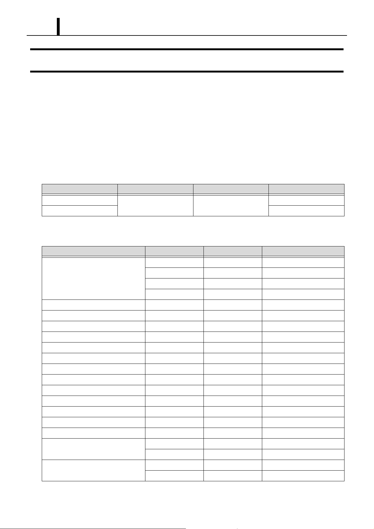
z The common rail system for the MZR-CD engine has been newly installed in the Mazda 5 and Mazda 6. The contents for the common
rail system are basically the same as those published in the previous Service Bulletin, "S/B Code: ECD02-06, Subject: New Common
Rail System (ECD-U2P) for Mazda." The two major points that have changed for this system are the addition of the DPF system, and
injectors equipped with the QR code. Please be sure to use this Service Manual together with the Service Bulletin as this edition ex-
plains only points that have changed.
1.2 Application
Model Name Engine Destination Line Off Period
MAZDA 5
MZR-CD Europe
MAZDA 6 April, 2005
March, 2005
1.3 System Components Parts Number
Parts Name DENSO P/N Manufacturer P/N Remarks
275800-6401 RF7J 18 881B MAZDA 6
Engine ECU
Turbo pressure sensor (MAPS) 079800-7440 RF7J 18 211
Injector 095000-5780 RF7J 13 H50
Crankshaft position sensor (NE) 949979-0200 RF7J 18 221
Cylinder recognition sensor (TDC) 949979-1520 RF7J 18 230
Rail 095440-0740 RF7J 13 GC0
Rail pressure sensor 499000-6210 —
Pressure limiter 095420-0201 —
Supply pump 294000-0420 RF7J 13 800A
Suction control valve 294200-0160 —
Fuel temperature sensor 179730-0020 RF1L 18 840
Mass air flow meter 197400-2010 ZL01 13 215
275800-6441 RF7K 18 881B MAZDA 6 High Output Engine
275800-6450 RF7N 18 881A MAZDA 5
275800-6460 RF7P 18 881A MAZDA 5 High Output Engine
Coolant temperature sensor 179700-0220 B593 18 840A
Engine compartment temperature sensor 170400-6020 BP4W 18 845
Exhaust temperature sensor 1
Exhaust temperature sensor 2
265600-1050 RF7N 18 7G0 MAZDA 6
265600-1090 RF7K 18 7G0A MAZDA 5
265600-1060 RF7P 18 7G0 MAZDA 6
265600-1080 RF7J 18 7G0A MAZDA 5
Page 5

Operation Section
Parts Name DENSO P/N Manufacturer P/N Remarks
1–2
Exhaust temperature sensor 3
265600-1070 RF7R 18 7G0 MAZDA 6
265600-1101 RF7L 18 7G0C MAZDA 5
A/F sensor (UHEGO) 211200-4260 RF7N 18 8G1
104990-1160 RF7N 18 2B5 MAZDA 6
Differential pressure sensor
104990-1150 RF7J 18 2B5 MAZDA 5
198800-3480 CC30 41 600
198800-3490 CC34 41 600
198800-3400 GR1L 41 600A
Accele pedal module
198800-3410 GR1M 41 600A
198800-3440 GR3D 41 600A
198800-3450 GR3E 41 600A
MAZDA 6
MAZDA 5
Page 6
1–3
Operation Section
2. OUTLINE OF SYSTEM
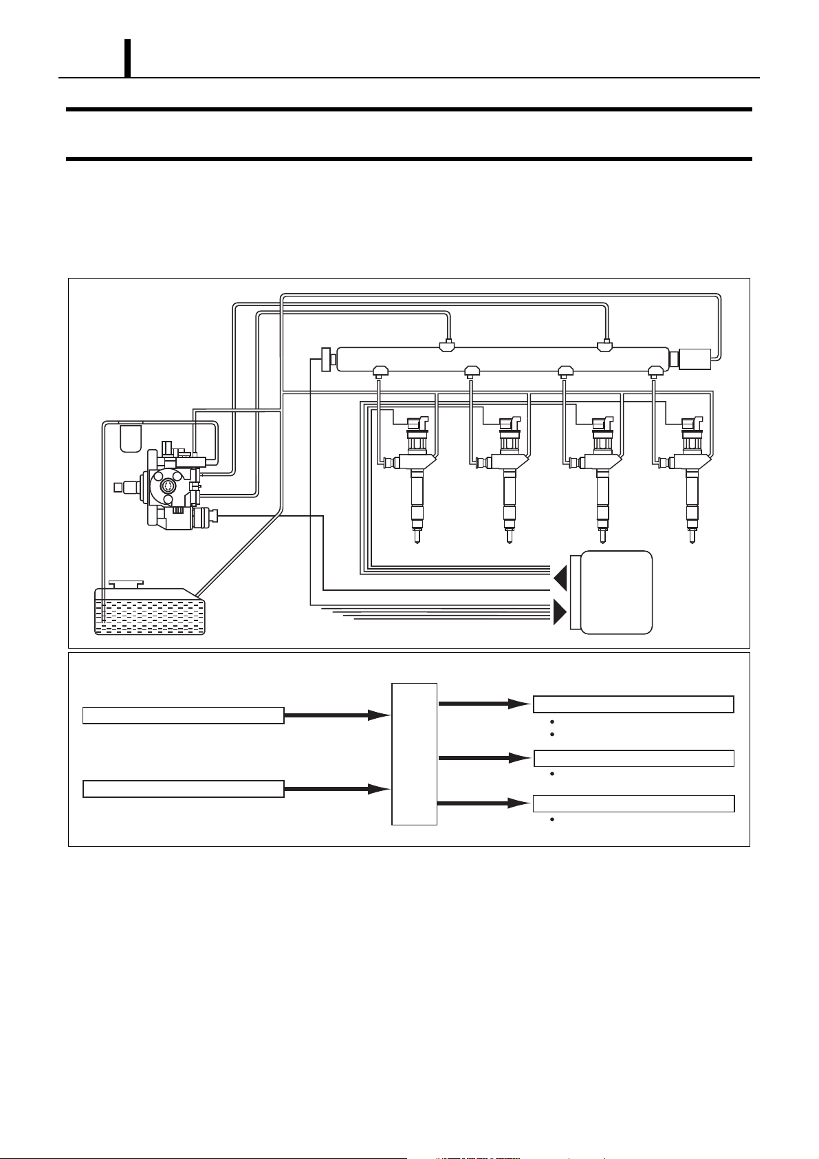
2.1 Outline of Composition and Operation
z This system is basically the same as that in Service Bulletin ECD02-06. However the EDU has been discontinued. Please refer to the
Service Bulletin for Operation.
Fuel filter
Supply pump
Fuel tank
Sensors
Engine speed sensor
Other sensors and switches
Fuel pressure
sensor
Various
sensors
Engine Speed
Engine
ECU
Pressure
limiter
Rail
Injector
Engine
ECU
Q001109E
Actuators
Injector
Fuel injection quantity control
Injection timing control, etc.
Supply pump
Fuel pressure control
Other actuators
EMS control
Q001110E
Page 7
Operation Section
1–4
3. SUPPLY PUMP
3.1 Outline
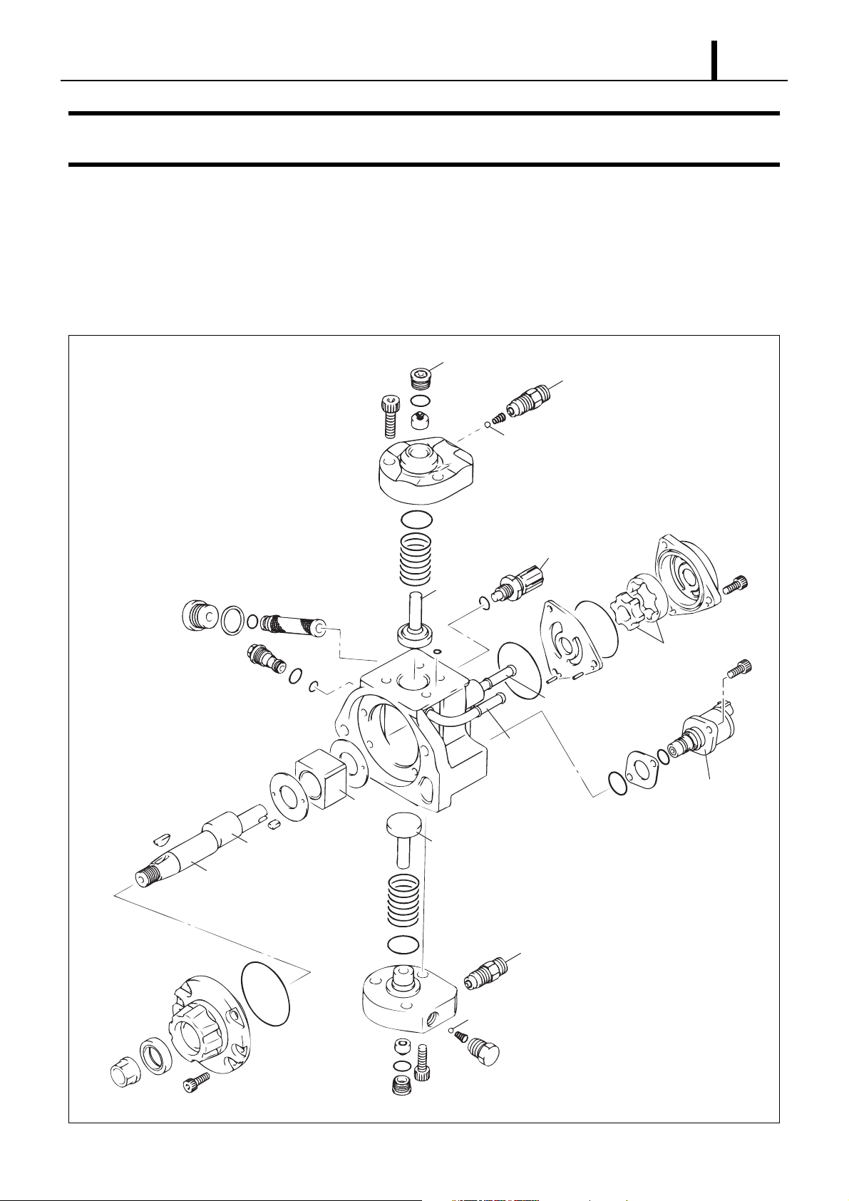
z The HP3 supply pump comes with the compact SCV (Suction Control Valve) installed. Please refer to Service Bulletin ECD02-06 as
only the SCV has changed.
3.2 Explode View
Suction valve
Discharge outlet
Delivery valve
Eccentric cam
Camshaft
Ring cam
Fuel temperature
sensor
Plunger
Feed pump
Fuel suction inlet
Overflow
fuel outlet
Suction control
valve (SCV)
Plunger
Discharge outlet
Delivery valve
Q001112E
Page 8
1–5
Operation Section
3.3 SCV (Suction Control Valve)
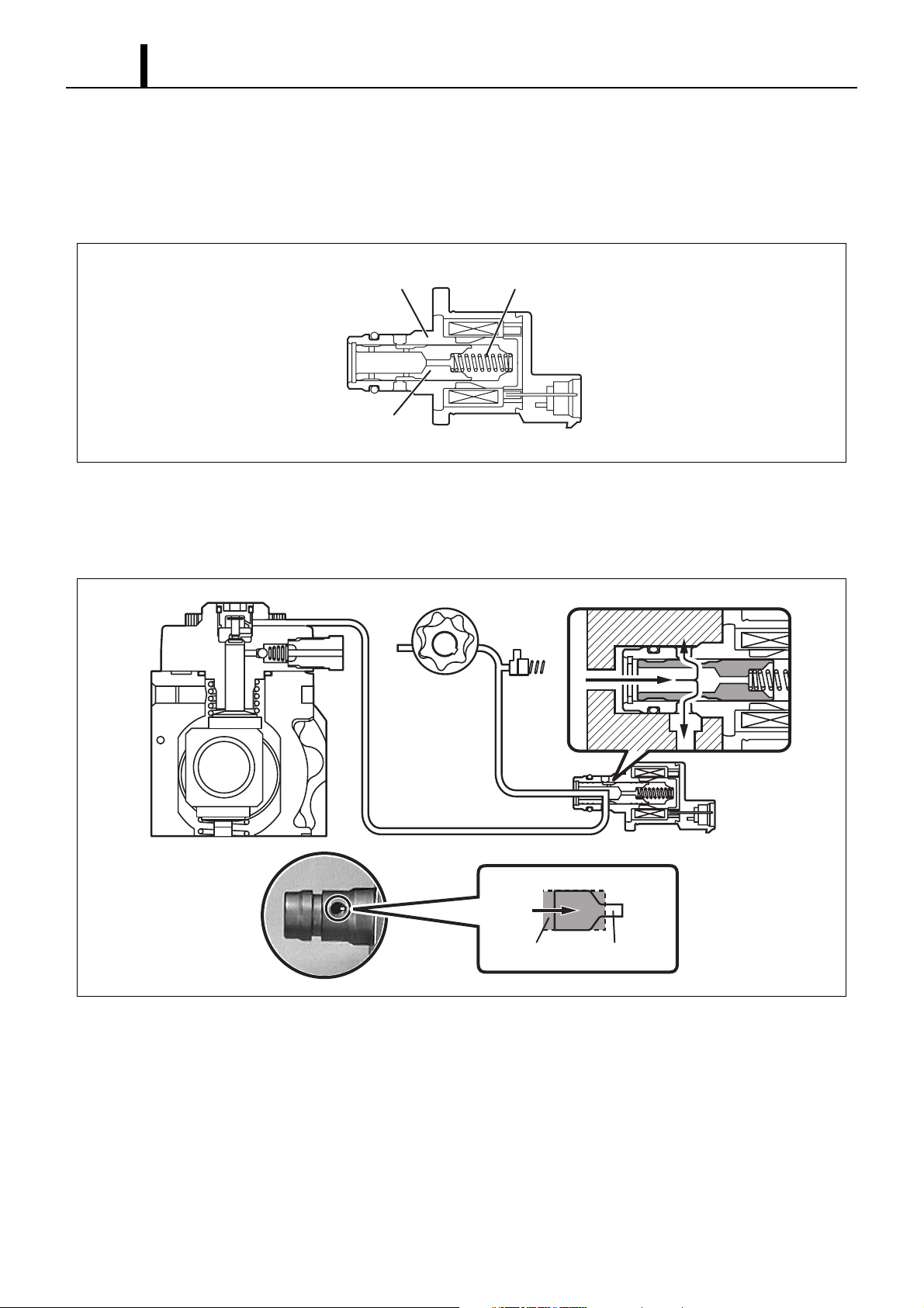
z A linear solenoid type solenoid valve has been adopted. The length of time in which the ECU applies current to the SCV is controlled
(duty cycle control) in order to regulate the volume of suction of fuel into the pumping area. Because only the volume of fuel that is
required by the target rail pressure is drawn in, the drive load on the supply pump decreases, thus resulting in improved fuel economy.
Valve body
Needle valve
Return Spring
Q001113E
(1) SCV Opening Small (Duty ON time long - Refer to the "Relationship Between Actuation
Signal and Current" Diagram.)
• When the opening of the SCV is small, the fuel suction area is kept small, which decreases the transferable fuel volume.
Feed Pump
Needle valve Small Opening
Q001114E
Page 9
Operation Section
1–6
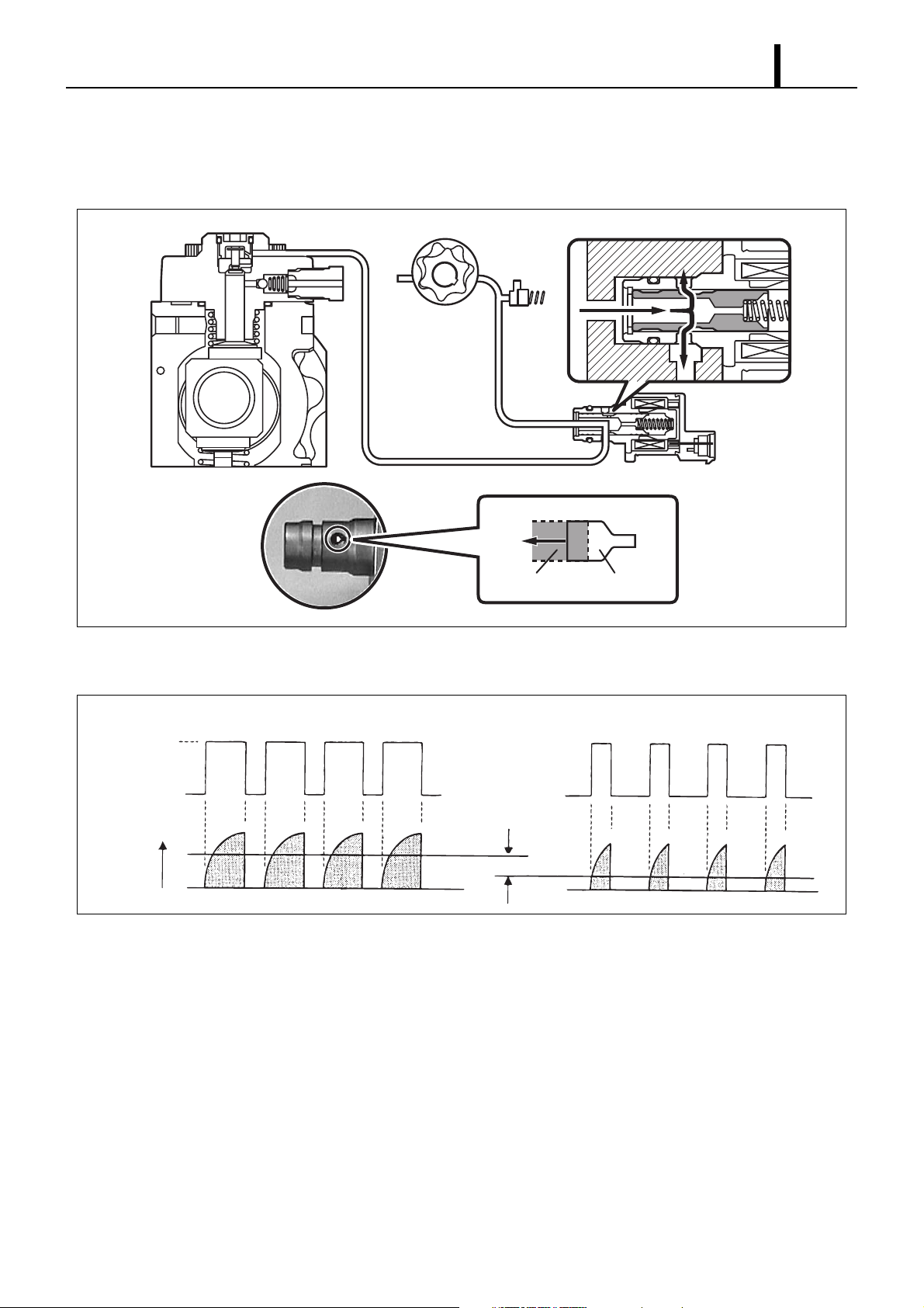
(2) SCV Opening Large (Duty ON time short - Refer to the "Relationship Between Actuation
Signal and Current" Diagram.)
• When the opening of the SCV is large, the fuel suction area is kept large, which increases the transferable fuel volume.
Feed Pump
Needle valve Large Opening
Q001115E
(3) Diagram of Relationship Between Actuation Signal and Current (Magnetomotive Force)
Small Suction Volume Large Suction Volume
ON
Actuation
Voltage
OFF
Current
Average Current Difference
Q001116E
Page 10
1–7
Operation Section
4. RAIL
4.1 Outline
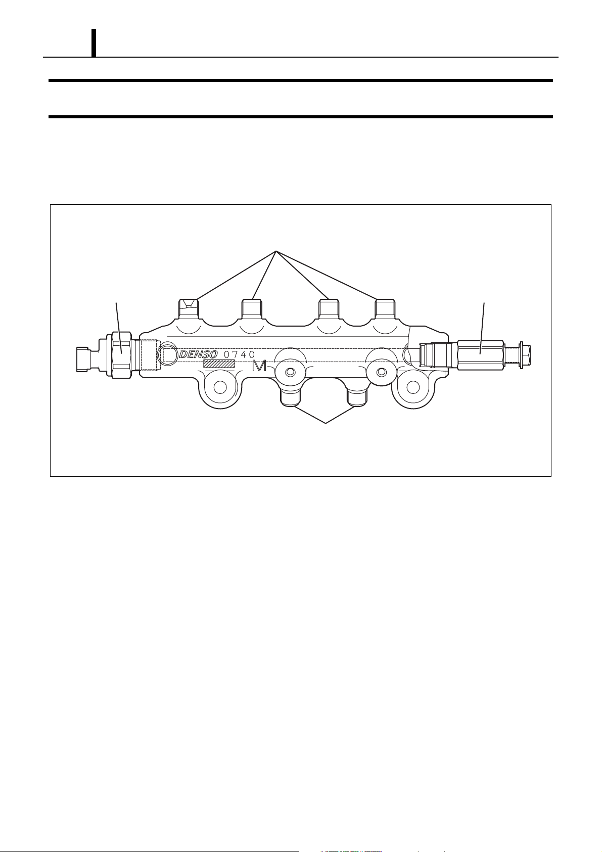
z Although the characteristics of both the Fuel Pressure Sensor and Pressure limiter have not changed, the shape of the Rail Pressure
Sensor has been altered. Please refer to Service Bulletin ECD02-06.
To injector
Rail pressure sensor Pressure limiter
From supply pump
Q001117E
Page 11
Operation Section
1–8
5. INJECTOR
5.1 Outline
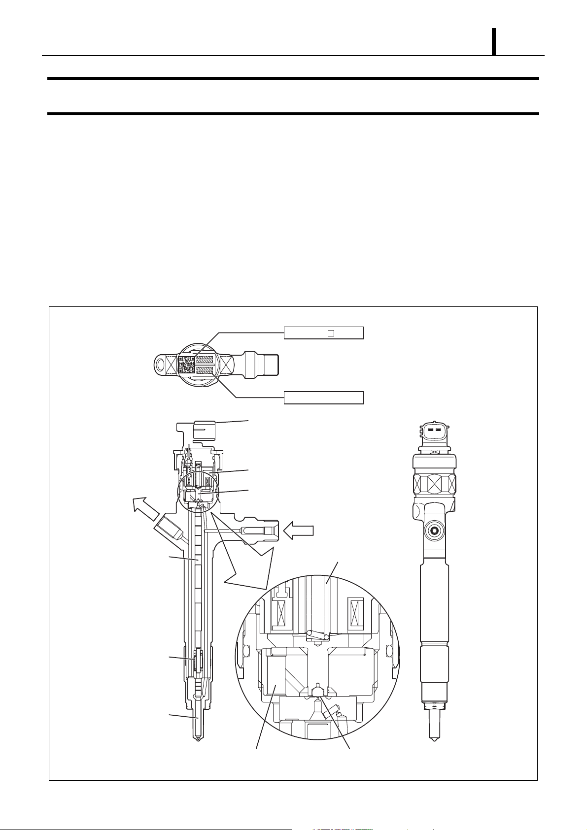
z The injectors inject the high-pressure fuel from the rail into the combustion chambers at the optimum injection timing, rate, and spray
condition in accordance with the commands received from the ECU. In addition, the correction resistor has been discontinued and
replaced by a QR code injector.
5.2 Characteristics
z A compact, energy-saving, solenoid-control type TWV (Two-Way Valve) injector has been adopted.
5.3 Construction
To fuel tank
Command position
QR Codes ( 9.9mm)
Connector
Solenoid valve
TWV
High-pressure fuel
(from rail)
ID Codes
Valve spring
Nozzle spring
Nozzle needle
Seat areaLeak passage
Q001118E
Page 12
1–9
Operation Section
5.4 QR Codes
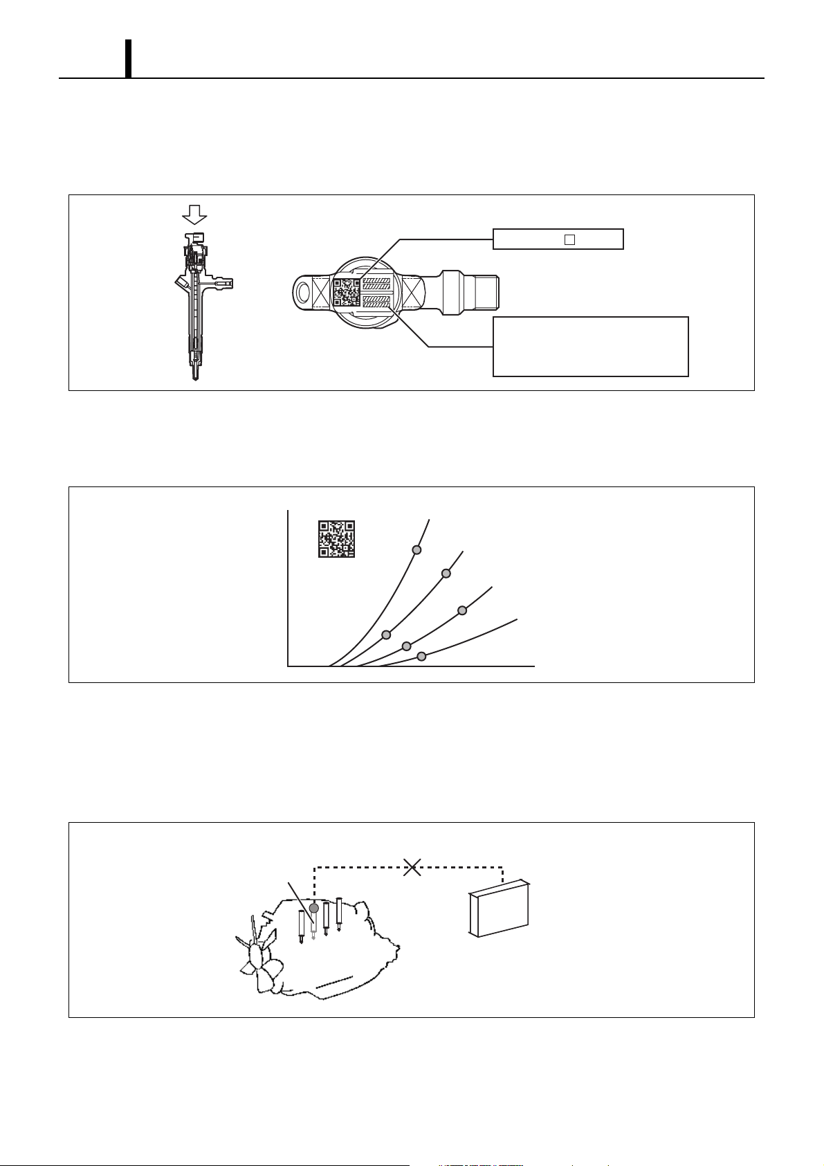
z Conventionally the whole injector Ass'y was replaced during injector replacement, but QR (Quick Response) codes have been adopted
to improve injector quantity precision.
QR Codes ( 9.9mm)
ID Codes (30 base 16 characters)
Base 16 characters noting fuel
injection quantity correction
information for market service use
z QR codes have resulted in a substantial increase in the number of fuel injection quantity correction points, greatly imimproving pre-
cision. The characteristics of the engine cylinders have been further unified, contributing to improvements in combustion efficiency,
reductions in exhaust gas emissions and so on.
Q001119E
Injection Quantity Q
QR Codes
Actuating Pulse Width TQ
Q001132E
(1) Repair Procedure Changes (Reference)
• When replacing injectors with QR codes, or the engine ECU, it is necessary to record the ID codes in the ECU. (If the ID codes for
the installed injectors are not registered correctly, engine failure such as rough idling and noise will result). The ID codes will be reg-
istered in the ECU at a MAZDA dealer using approved MAZDA tools.
Replacing the Injector
"No correction resistance, cannot be detected electrically"
Replaced injector
Engine ECU
* Injector ID code must be registered with the engine ECU
Q001133E
Page 13

Replacing the Engine ECU
"No correction resistance, cannot be detected electrically"
Vehicle injectors
Operation Section
1–10
Replaced engine ECU
* Injector ID code must be registered with the engine ECU
Q001134E
Page 14
1–11
Operation Section
6. OPERATION OF CONTROL SYSTEM COMPONENTS
6.1 Outline
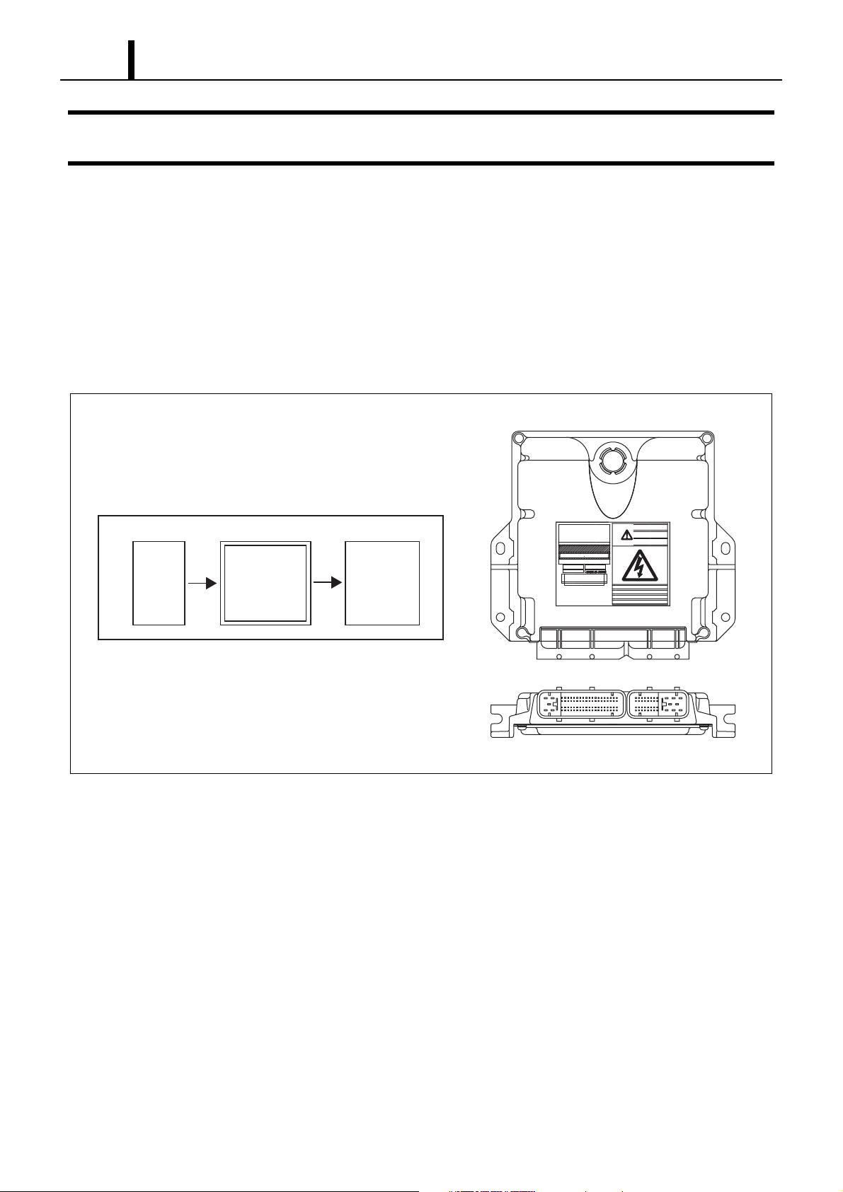
z The EDU (Electronic Driving Unit) functions have been built into the Engine ECU (Electronic Control Unit). Therefore the EDU has
been done away with. In addition the system sensor has been changed. Please refer to Service Bulletin ECD02-06 as only this sensor
has changed.
6.2 Engine ECU (Electronic Control Unit)
z This is the command center that controls the fuel injection system and the engine operation in general.
Sensor
Detection
<Outline Diagram>
Engine ECU
Calculation
Actuator
Actuation
Q001135E
Page 15
Operation Section
1–12
6.3 Operation of Sensors
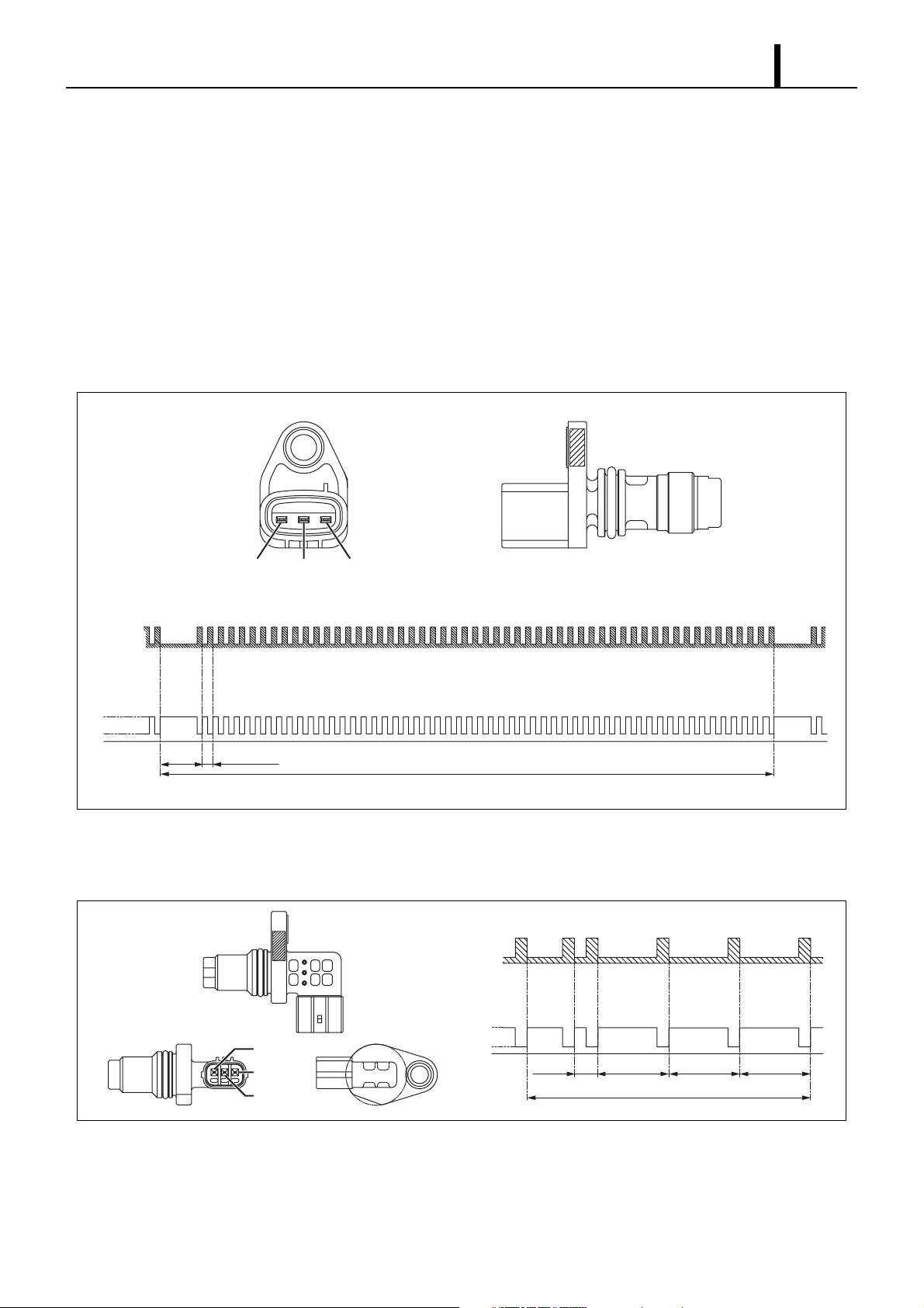
z The Crankshaft Position Sensor (NE Sensor) as well as the Cylinder Recognition Sensor (TDC Sensor) have been changed to the MRE
(Magnetic Resistance Element) type. For the MRE type, when the pulsar passes the sensor, the magnetic resistance changes and the
voltage passing through the sensor changes. The change in voltage is amplified by the internal IC circuit and is output to the engine
ECU. In addition the Intake Air Pressure Sensor (MAPS) output characteristics have also changed.
(1) Crankshaft Position Sensor (NE Sensor)
• An NE pulsar is mounted on the crankshaft timing gear in order to output the signals that are used for detecting the crankshaft position.
The pulsar gear consists of 55 teeth and 5 missing tooth per pulse, thus enabling the sensor to output 55 pulses for every revolution
(360
°CA) of the crankshaft.
OUT GND VOPT
Pulser
Sensor
Signal
5V
1V
0V
30°CA 55×6°CA
360°CA
(2) Cylinder Recognition Sensor (TDC Sensor)
• Outputs a cylinder identification signal. The sensor outputs 5 pulses for every two revolutions (720°CA) of the engine.
Pulser
Sensor
Signal
5V
OUT
OPT
V
GND
1V
0V
15°CA 90°CA 90°CA
90°CA
360°CA
Q001138E
Q001139E
Page 16
1–13
Operation Section
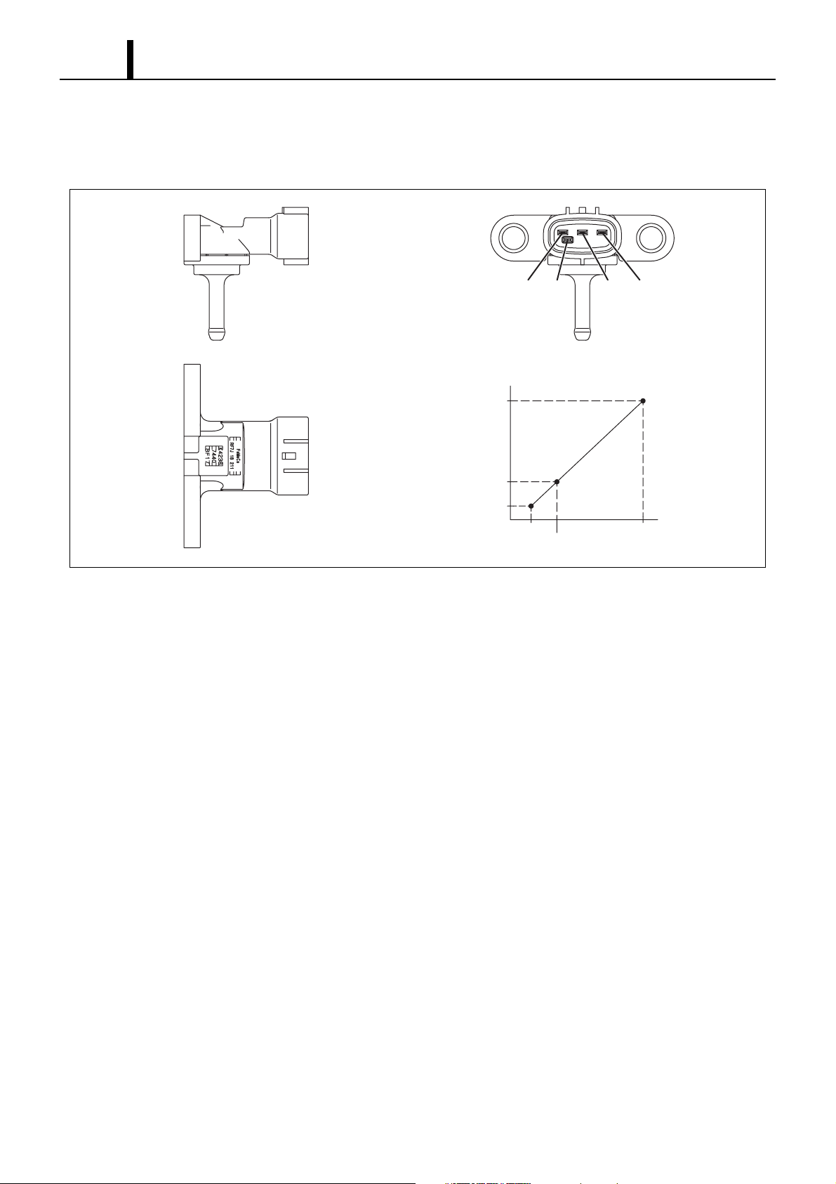
(3) Turbo Pressure Sensor
• This is a semiconductor type pressure sensor, which utilizes the electrical resistance of the silicon element that changes with the chang-
es in the pressure that is applied to the silicon element.
VIN TRIM VOUT GND
VOUT
(V)
3.357
VIN = 5V
1.071
0.386
40
99.992
300
kPa
[abs]
Q001140E
Page 17
Operation Section
1–14
7. CONTROL SYSTEM
7.1 Outline
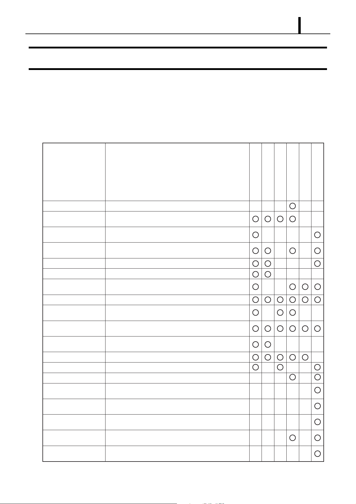
z A new DPF (Diesel Particulate Filter) has been added to the control system. In addition, control regarding the system has been
changed. Please refer to Service Bulletin ECD02-06 as only these controls have changed.
(1) Sensor System
Sensor Name Function
Airflow meter Uses a hot wire to detect the intake airflow rate.
Air temperature sensor
Intake air temperature
sensor
Coolant temperature sensor
Rail pressure sensor Detects the fuel pressure in the rail.
Fuel temperature sensor Detects the fuel temperature in the supply pump
Turbo pressure sensor
Air pressure sensor Detects the air pressure.
Accelerator position sensor
Crankshaft position sensor (NE sensor)
Cylinder recognition
sensor (TDC sensor)
Starter signal This is the starter voltage signal during starting.
Vehicle speed sensor Detects the vehicle speed.
Located in the airflow meter, this sensor detects the intake
air temperature.
Detects the intake air temperature past the turbocharger.
Detects the water temperature.
Detects the intake air pressure.
Attached to the accelerator pedal, this sensor detects the
travel of the accelerator pedal.
Detects the engine speed based on the crankshaft position.
Identifies the cylinder based on the rotation of the rotor
attached to the camshaft.
Fuel Injection
Rail Pressure
Intake Restriction
EGR
VGT
DPF
A/F Sensor (UHEGO) Detects the exhaust gas A/F value.
Differential Pressure
Sensor
Exhaust Temperature
Sensor 1
Exhaust Temperature
Sensor 2
Exhaust Temperature
Sensor 3
Engine Compartment
Temperature Sensor
Detects pressure both before and after the DPF.
Detects the exhaust temperature before the DPF.
Detects the exhaust temperature inside the DPF.
Detects the exhaust temperature after the DPF.
Detects the ambient temperature in the vicinity of the engine
compartment differential pressure sensor.
Q001141E
Page 18
1–15
Operation Section
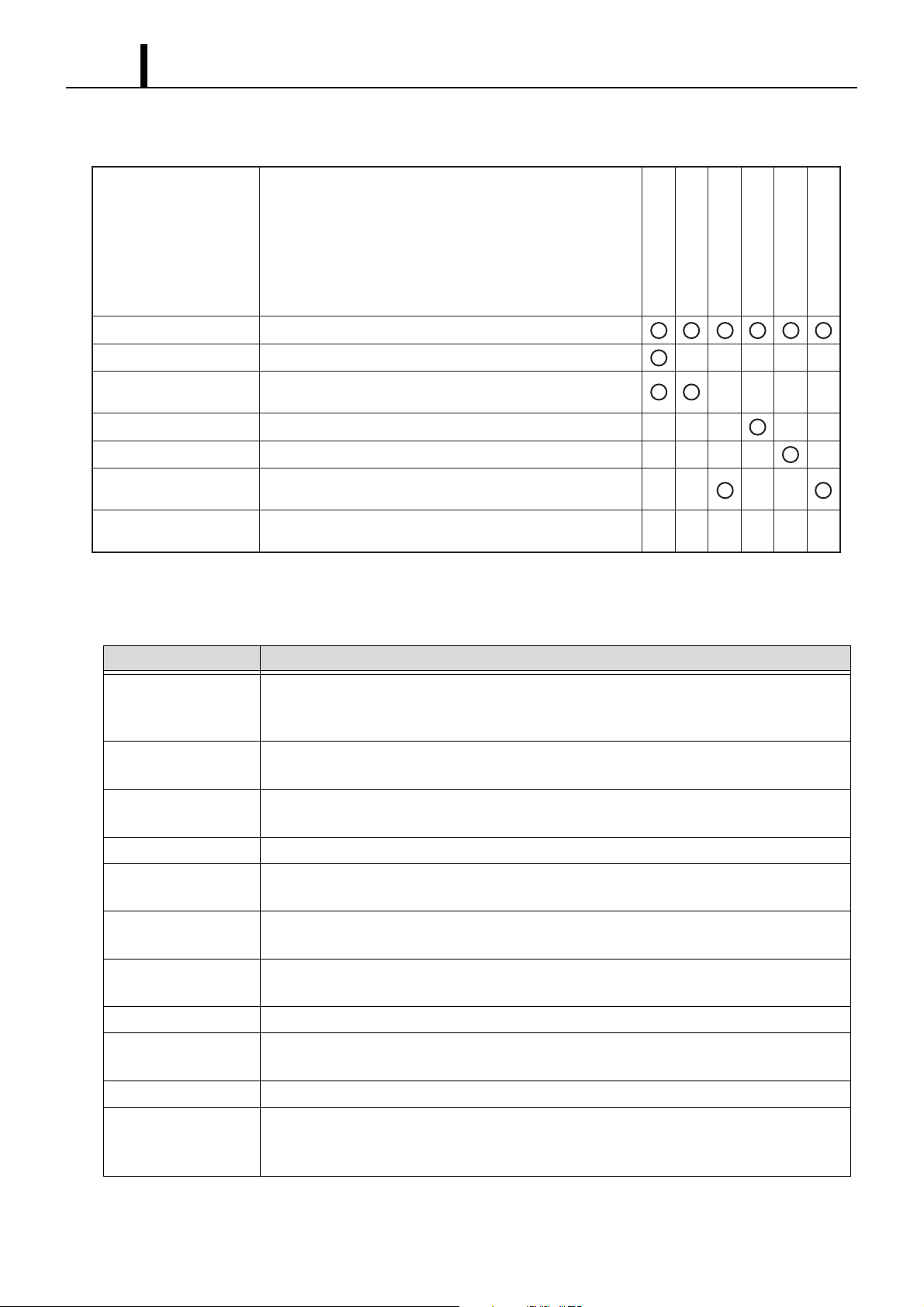
(2) Actuator System
Actuator Name Function
Main relay Supplies power to the system.
Injector Precisely injects fuel.
Fuel Injection
Rail Pressure
Intake Restriction
EGR
VGT
DPF
Suction control valve
EGR Valve DC Motor Controls the vacuum that is applied to the EGR valve.
VGT E-VRV Controls the vacuum that is applied to the turbo.
Electronic Control Throttle
DC Motor
Fan relay
Controls the volume of fuel that is supplied to the supply
pump.
Controls the vacuum that is applied to the intake suction
valve.
Controls the duration of time in which the current is applied
to the electric fan.
Q001179E
(3) Control System
Control Name Function
Fuel injection control Controls the injectors' fuel injection timing and injection quantity by adding corrections based on the
signals from the sensors to the basic injection duration, which is calculated in accordance with the con-
ditions of the engine.
Rail pressure control Controls the rail pressure by sending signals to the suction control valve of the supply pump in accor-
dance with the conditions of the engine.
VGT control Controls the boost pressure by calculating the signals that are output to the E-VRV in accordance with
the operating conditions.
Intake restriction control Controls the opening of the intake restriction mechanism in accordance with the driving conditions.
EGR control Controls the opening of the EGR valve by calculating the signals that are output in accordance with the
operating conditions.
Glow plug relay control Controls the duration of the current that is applied to the glow plug relay in accordance with the water
temperature during the starting of the engine.
Air conditioner cutoff
control
Diagnosis Illuminates a warning light to alert the driver if a failure occurs in the computer.
Auto cruise control Effects feedback control of the actual vehicle speed to match the speed that is set in accordance with the
DSC control Effects traction control and ABS control in accordance with the driving conditions.
DPF Control Data from the differential pressure sensor, exhaust temperature sensor, airflow sensor, etc, are accumu-
Cuts off the air conditioner during acceleration to improve drivability.
cruise control switch.
lated in the DPF and used to estimate the PM (Particulate Matter) volume as well as perform proper
combustion (PM combustion).
Page 19
Operation Section
1–16
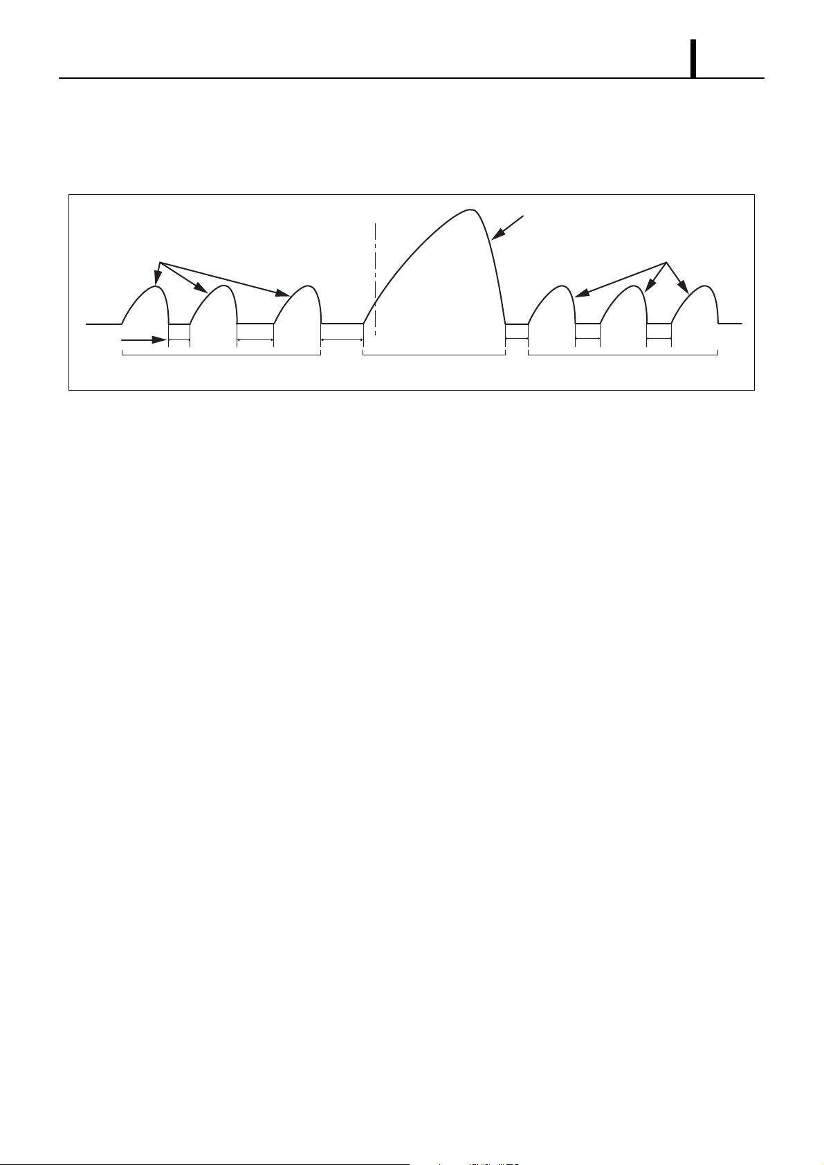
7.2 Fuel Injection Timing Control
z Multi-Injection Control has changed due to the items attached to the DPF. Post2 and Post3 injections have been added due to the state
of the DPF.
Pilot injection
QPL1 QPL2
Interval
Reduced noise through
pre-mixture combustion
Top-dead-center
QMAIN
QPL3 POST1 POST2 POST3
Exhaust gas
&
performance
Output performance
Main injection
Exhaust gas
performance
Post-main injection
& DPF Control
Q001180E
Page 20
1–17
Operation Section
8. DIAGNOSTIC TROUBLE CODES (DTC)
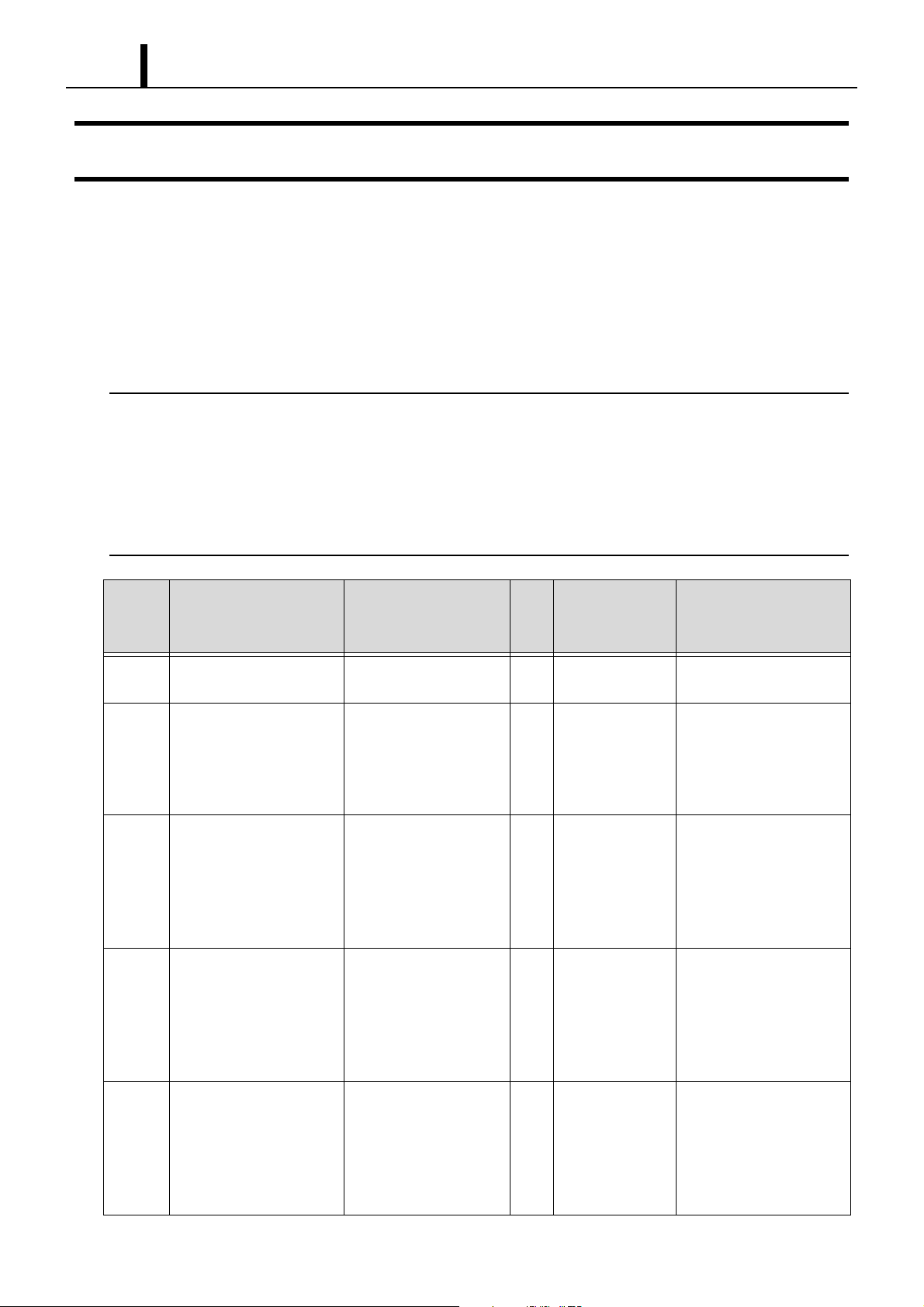
8.1 About the Codes Shown in the Table
z The "SAE" diagnostic trouble code indicates the code that is output through the use of the STT (WDS). (SAE: Society of Automotive
Engineers)
8.2 Diagnostic Trouble Code Details
< NOTE >
*1 : In the event that the code "DTC0088" is displayed when using a diagnostic tool, there is a possibility that the injectors have exceeded the guarantee limit
(engine speed and fuel pressure parameters). Replace all injectors.
*2 : In the event that the code "DTC0089" is displayed when using a diagnostic tool, there is a possibility that the pressure limiter is open. Replace the rail.
*3 : In the event that the code "DTC1211" is displayed when using a diagnostic tool, there is a possibility of damage to one of the pump cylinders. However, if
the MIL lamp is on, verify that the vehicle is not out of gas. If there is even a small amount of residual fuel, refill the tank and check the MIL lamp again.
If the MIL lamp is still on, replace the pump.
*4 : In the event that the code "DTC1281" is displayed when using a diagnostic tool, there is a possibility that the pump has exceeded the guarantee limit
(engine speed and fuel pressure parameters). Replace the pump.
*5 : In the event that the code "DTC1329" is displayed when using a diagnostic tool, there is a possibility that the pump has exceeded the guarantee limit
(engine speed and fuel pressure parameters). Replace the pump.
DTC
Number
SAE
P0563 Battery voltage high
P0562 Battery voltage low
P0118 Coolant temperature sensor
P0117 Coolant temperature sensor
P0116 Abnormal coolant tempera-
Diagnosis Item
[Terminal]
[Battery terminal]
[Battery terminal]
high
[Coolant temperature sensor
terminal]
low
[Coolant temperature sensor
terminal]
ture sensor characteristics
[Coolant temperature sensor
terminal]
Description of Diagnosis
1: Diagnosis condition
2: Failure state
1: Key ON and starter OFF
2: Out of range
1: Key ON and starter OFF
2: Out of range
1: Key On and battery nor-
mal
2: Out of range
1: Key ON and battery nor-
mal
2: Out of range
When in an expected tem-
perature rise situation, a
small change in output
detected.
LightONMain Malfunction
Symptom
Yes ECU, sensor(s),
actuator damage
Yes ECU reset, sensor,
poor actuator oper-
ation, poor emis-
sions, poor
driveability
Yes Worsening emis-
sions, decrease in
low temperature
startablilty,
decrease in drive-
ability
Yes Worsening emis-
sions, decrease in
low temperature
startablilty,
decrease in drive-
ability
Yes Worsening emis-
sions, decrease in
low temperature
startablilty,
decrease in drive-
ability
Inspection Area
Battery, ECU, ECU-battery
wiring harness, connector
Battery, ECU, ECU-battery
wiring harness, connector
Coolant temperature sensor,
ECU, ECU-sensor wiring
harness, connector
Coolant temperature sensor,
ECU, ECU-sensor wiring
harness, connector
Coolant temperature sensor,
ECU, ECU-sensor wiring
harness, connector
Page 21

Operation Section
1–18
DTC
Number
SAE
P0098 Intake air temperature sensor
P0097 Intake air temperature sensor
P0096 Abnormal intake air sensor
Diagnosis Item
[Terminal]
high
[Intake air temperature sen-
sor terminal]
low
[Intake air temperature sen-
sor terminal]
characteristics
[Intake air temperature sen-
sor terminal]
Description of Diagnosis
1: Diagnosis condition
2: Failure state
1: Key ON and battery nor-
mal
2: Out of range
1: Key ON and battery nor-
mal
2: Out of range
When in an expected tem-
perature rise situation, a
small change in output
detected.
LightONMain Malfunction
Symptom
Yes Worsening emis-
sions, decrease in
low temperature
startablilty,
decrease in drive-
ability
Yes Worsening emis-
sions, decrease in
low temperature
startablilty,
decrease in drive-
ability
Yes Worsening emis-
sions, decrease in
low temperature
startablilty,
decrease in drive-
ability
Inspection Area
Intake air temperature sen-
sor, ECU, ECU-sensor wir-
ing harness, connector
Intake air temperature sen-
sor, ECU, ECU-sensor wir-
ing harness, connector
Intake air temperature sen-
sor, ECU, ECU-sensor wir-
ing harness, connector
P0113 Ambient temperature sensor
high
[Ambient temperature sensor
terminal]
P0112 Ambient temperature sensor
low
[Ambient temperature sensor
terminal]
P0111 Abnormal ambient tempera-
ture sensor characteristics
[Ambient temperature sensor
terminal]
P0183 Fuel temperature sensor high
[Fuel temperature sensor ter-
minal]
P0182 Fuel temperature sensor low
[Fuel temperature sensor ter-
minal]
1: Key ON and battery nor-
mal
2: Out of range
1: Key ON and battery nor-
mal
2: Out of range
When in an expected tem-
perature rise situation, a
small change in output
detected.
1: Key ON and battery nor-
mal
2: Out of range
1: Key ON and battery nor-
mal
2: Out of range
Yes Worsening emis-
sions, decrease in
low temperature
startablilty,
decrease in drive-
ability
Yes Worsening emis-
sions, decrease in
low temperature
startablilty,
decrease in drive-
ability
Yes Worsening emis-
sions, decrease in
low temperature
startablilty,
decrease in drive-
ability
Yes Worsening emis-
sions
Yes Worsening emis-
sions
Ambient temperature sen-
sor, ECU, ECU-sensor wir-
ing harness, connector
Ambient temperature sen-
sor, ECU, ECU-sensor wir-
ing harness, connector
Ambient temperature sen-
sor, ECU, ECU-sensor wir-
ing harness, connector
Fuel temperature sensor,
ECU, ECU-sensor wiring
harness, connector
Fuel temperature sensor,
ECU, ECU-sensor wiring
harness, connector
P0181 Abnormal fuel temperature
sensor characterisitcs
[Fuel temperature sensor ter-
minal]
When in an expected tem-
perature rise situation, a
small change in output
detected.
No Worsening emis-
sions
Fuel temperature sensor,
ECU, ECU-sensor wiring
harness, connector
Page 22

1–19
Operation Section
DTC
Number
SAE
P0193 Rail pressure sensor high
P0192 Rail pressure sensor low
P0191 Abnormal rail pressure sen-
P0108 Turbo pressure sensor high
P0107 Turbo pressure sensor low
P0106 Abnormal turbo pressure
Diagnosis Item
[Terminal]
[Rail pressure sensor termi-
nal]
[Rail pressure sensor termi-
nal]
sor characterisitcs
[Rail pressure sensor termi-
nal]
[Turbo pressure sensor ter-
minal]
[Turbo pressure sensor ter-
minal]
sensor characteristics
[Turbo pressure sensor ter-
minal]
Description of Diagnosis
1: Diagnosis condition
2: Failure state
1: Key ON and battery nor-
mal
2: Out of range
1: Key ON and battery nor-
mal
2: Out of range
When rail pressure sensor
output should be changing,
sensor output change is
small.
1: Key ON and battery nor-
mal
2: Out of range
1: Key ON and battery nor-
mal
2: Out of range
When turbo pressure sen-
sor output should be
changing, sensor output
change is small.
LightONMain Malfunction
Symptom
Yes PC control impos-
sible, poor driveab-
lilty, worsening
emissions
Yes PC control impos-
sible, poor driveab-
lilty, worsening
emissions
Yes PC control impos-
sible, poor driveab-
lilty, worsening
emissions
Yes Worsening emis-
sions, decrease in
driveability
Yes Worsening emis-
sions, decrease in
driveability
Yes Worsening emis-
sions, decrease in
driveability
Inspection Area
Rail pressure sensor, ECU,
ECU-sensor wiring harness,
connector
Rail pressure sensor, ECU,
ECU-sensor wiring harness,
connector
Rail pressure sensor, ECU,
ECU-sensor wiring harness,
connector
Turbo pressure sensor, ECU,
ECU-sensor wiring harness,
connector
Turbo pressure sensor, ECU,
ECU-sensor wiring harness,
connector
Turbo pressure sensor, ECU,
ECU-sensor wiring harness,
connector
P2229 Atmospheric pressure sen-
sor high
[Atmospheric pressure sen-
sor terminal]
P2228 Atmospheric pressure sen-
sor low
[Atmospheric pressure sen-
sor terminal]
P2227 Abnormal atmospheric pres-
sure sensor characteristics
[Atmospheric pressure sen-
sor terminal]
P0123 Accelerator sensor 1 high
[Accelerator sensor 1
(TV01) terminal]
P0122 Accelerator sensor 1 low
[Accelerator sensor 1
(TV01) terminal]
P2135 Accelerator 1 intermediate
malfunction
[Accelerator sensor 1, 2
(TV01, 2) terminal]
1: Key ON and battery nor-
mal
2: Out of range
1: Key ON and battery nor-
mal
2: Out of range
1: During engine operation
2: Large difference in stan-
dard value and atmospheric
pressure
1: Key ON and battery nor-
mal
2: Out of range
1: Key ON and battery nor-
mal
2: Out of range
1: Key ON and battery nor-
mal
2: Voltage difference
detected
Yes Worsening emis-
sions, decrease in
driveability
Yes Worsening emis-
sions, decrease in
driveability
Yes Worsening emis-
sions, decrease in
driveability
Yes Accelerator con-
trol not possible
Yes No acceleration Accelerator sensor, ECU,
Yes Accelerator con-
trol not possible
Atmospheric pressure sen-
sor (built into the ECU),
ECU, ECU-sensor wiring
harness, connector
Atmospheric pressure sen-
sor (built into the ECU),
ECU, ECU-sensor wiring
harness, connector
Atmospheric pressure sen-
sor (built into the ECU),
turbo pressure sensor, ECU,
ECU-sensor wiring harness,
connector
Accelerator sensor, ECU,
ECU-sensor wiring harness,
connector
ECU-sensor wiring harness,
connector
Accelerator sensor, ECU,
ECU-sensor wiring harness,
connector
Page 23

Operation Section
1–20
DTC
Number
SAE
P0121 Accelerator sensor 1 abnor-
P0223 Accelerator sensor 2 high
P0222 Accelerator sensor 2 low
P0103 Mass airflow sensor high
P0102 Mass airflow sensor low
P0101 Abnormal mass airflow sen-
Diagnosis Item
[Terminal]
mal characterisitcs
[Accelerator sensor 1, 2
(TV01, 2) terminal]
[Accelerator sensor 2
(TV02) terminal]
[Accelerator sensor 2
(TV02) terminal]
[Mass airflow sensor termi-
nal]
[Mass airflow sensor termi-
nal]
sor characterisitcs
[Mass airflow sensor termi-
nal]
Description of Diagnosis
1: Diagnosis condition
2: Failure state
1: Key ON and battery nor-
mal
2: Sensor 1, 2 voltage dif-
ference observed
1: Key ON and battery nor-
mal
2: Out of range
1: Key ON and battery nor-
mal
2: Out of range
1: Key ON and battery nor-
mal
2: Out of range
1: Key ON and battery nor-
mal
2: Out of range
1: During engine operation
2: Abnormal flow volume
value detected
LightONMain Malfunction
Symptom
Yes Accelerator con-
trol not possible, no
acceleration
Yes Heavy idle vibra-
tion
Yes Heavy idle vibra-
tion
Yes Output insuffi-
cient, worsening
emissions
Yes Worsening emis-
sions
Yes Output insuffi-
cient, worsening
emissions
Inspection Area
Accelerator sensor, ECU,
ECU-sensor wiring harness,
connector
Accelerator sensor, ECU,
ECU-sensor wiring harness,
connector
Accelerator sensor, ECU,
ECU-sensor wiring harness,
connector
Mass airflow sensor, ECU,
ECU-sensor wiring harness,
connector
Mass airflow sensor, ECU,
ECU-sensor wiring harness,
connector
Mass airflow sensor, intake
air temperature sensor, turbo
pressure sensor, EGR actua-
tor, ECU, ECU-sensor wir-
ing harness, connector
P0406 EGR lift sensor high
[EGR lift sensor terminal]
P0405 EGR lift sensor low
[EGR lift sensor terminal]
P0545 Exhaust temperature sensor
U low
[Exhaust temperature sensor
1 terminal (before DOC)]
P0546 Abnormal exhaust tempera-
ture sensor U characterisitcs
[Exhaust temperature sensor
1 terminal (before DOC)]
P0548 Exhaust temperature sensor
M low
[Exhaust temperature sensor
2 terminal (before DPF)]
P0549 Abnormal exhaust tempera-
ture sensor M characterisitcs
[Exhaust temperature sensor
2 terminal (before DPF)]
1: Key ON and battery nor-
mal
2: Out of range
1: Key ON and battery nor-
mal
2: Out of range
1: Key ON and battery nor-
mal
2: Out of range
1: Key ON and battery nor-
mal
2: Out of range observed
1: Key ON and battery nor-
mal
2: Out of range observed
1: Key ON and battery nor-
mal
2: Out of range observed
Yes Output insuffi-
cient, worsening
emissions
Yes Worsening emis-
sions
Yes Output insuffi-
cient, worsening
emissions
Yes Output insuffi-
cient, worsening
emissions
Yes Output insuffi-
cient, worsening
emissions
Yes Output insuffi-
cient, worsening
emissions
EGR actuator, ECU, ECU-
sensor wiring harness, con-
nector
EGR actuator, ECU, ECU-
sensor wiring harness, con-
nector
Exhaust temperature sensor
1, ECU, ECU-sensor wiring
harness, connector
Exhaust temperature sensor
1, 2, 3, ECU, ECU-sensor
wiring harness, connector
Exhaust temperature sensor
2, ECU, ECU-sensor wiring
harness, connector
Exhaust temperature sensor
1, 2, 3, ECU, ECU-sensor
wiring harness, connector
Page 24

1–21
Operation Section
DTC
Number
SAE
P2032 Exhaust temperature sensor
P2033 Abnormal exhaust tempera-
P2455 Exhaust pressure sensor M
P2454 Exhaust pressure sensor M
P1392 Glow plug voltage high
P1391 Glow plug voltage low
Diagnosis Item
[Terminal]
L low
[Exhaust temperature sensor
3 terminal (before DPF)]
ture sensor L characterisitcs
[Exhaust temperature sensor
3 terminal (before DPF)]
high
[Exhaust pressure sensor ter-
minal]
low
[Exhaust pressure sensor ter-
minal]
[Glow plug relay terminal,
glow plug terminal]
[Glow plug relay terminal,
glow plug terminal]
Description of Diagnosis
1: Diagnosis condition
2: Failure state
1: Key ON and battery nor-
mal
2: Out of range observed
1: Key ON and battery nor-
mal
2: Out of range observed
1: Key ON and battery nor-
mal
2: Out of range observed
1: Key ON and battery nor-
mal
2: Out of range observed
1: Key ON and battery nor-
mal
2: Out of range observed
1: Key ON and battery nor-
mal
2: Out of range observed
LightONMain Malfunction
Symptom
Yes Output insuffi-
cient, worsening
emissions
Yes Output insuffi-
cient, worsening
emissions
Yes Output insuffi-
cient, worsening
emissions
Yes Output insuffi-
cient, worsening
emissions
No Dead battery, burnt
heater
No Decreased startab-
lilty
Inspection Area
Exhaust temperature sensor
3, ECU, ECU-sensor wiring
harness, connector
Exhaust temperature sensor
1, 2, 3, ECU, ECU-sensor
wiring harness, connector
Exhaust pressure sensor,
ECU, ECU-sensor wiring
harness, connector
Exhaust pressure sensor,
ECU, ECU-sensor wiring
harness, connector
Glow plug, glow plug relay,
ECU, ECU-sensor wiring
harness, connector
Glow plug, glow plug relay,
ECU, ECU-sensor wiring
harness, connector
P0132 A/F sensor + voltage high
[A/F output terminal (+
side)]
P0131 A/F sensor + voltage low
[A/F output terminal (+
side)]
P0152 A/F sensor - voltage high
[A/F output terminal (- side)]
P0151 A/F sensor - voltage low
[A/F output terminal (- side)]
P0134 A/F sensor + - terminal short
[A/F output terminal (+ -
side)]
1: Key ON and battery nor-
mal
2: Out of range observed
1: Key ON and battery nor-
mal
2: Out of range observed
1: Key ON and battery nor-
mal
2: Out of range observed
1: Key ON and battery nor-
mal
2: Out of range observed
1: Key ON and battery nor-
mal
2: Sensor + - terminal volt-
age difference observed
Yes Poor DPF recovery,
declining output,
worsening emis-
sions
Yes Poor DPF recovery,
declining output,
worsening emis-
sions
Yes Poor DPF recovery,
declining output,
worsening emis-
sions
Yes Poor DPF recovery,
declining output,
worsening emis-
sions
Yes Poor DPF recovery,
declining output,
worsening emis-
sions
A/F sensor, ECU, ECU-sen-
sor wiring harness, connec-
tor
A/F sensor, ECU, ECU-sen-
sor wiring harness, connec-
tor
A/F sensor, ECU, ECU-sen-
sor wiring harness, connec-
tor
A/F sensor, ECU, ECU-sen-
sor wiring harness, connec-
tor
A/F sensor, ECU, ECU-sen-
sor wiring harness, connec-
tor
P0030 A/F sensor heater abnormal-
ity
[A/F output terminal]
1: During engine operation
2: Current condition
observed
Yes Poor DPF recovery,
declining output,
worsening emis-
sions
A/F sensor, ECU, ECU-sen-
sor wiring harness, connec-
tor
Page 25

Operation Section
1–22
DTC
Number
SAE
P0133 Poor A/F sensor activation
P2148 Injector COM1 TMV actua-
P2147 Injector COM1 TMV actua-
P1378 Injector low charge
P0201 Injector TMV1 actuation
P0203 Injector TMV2 actuation
Diagnosis Item
[Terminal]
[A/F output terminal (+ -
side)]
tion system +B short
[Injector terminal, Injector
common terminal]
tion system ground short
[Injector terminal, Injector
common terminal]
[Injector terminal, Injector
common terminal]
system open circuit
[Injector terminal, Injector
common terminal]
system open circuit
[Injector terminal, Injector
common terminal]
Description of Diagnosis
1: Diagnosis condition
2: Failure state
1: During engine operation
2: Sensor output value
observed
1: During engine operation
2: Abnormal voltage at
unenergized terminal
1: During engine operation
2: Abnormal voltage at
unenergized terminal
1: During engine operation
2: Voltage observed
1: During engine operation
2: No peak current
1: During engine operation
2: No peak current
LightONMain Malfunction
Symptom
Yes Poor DPF recovery,
declining output,
worsening emis-
sions
Yes Poor driveability,
worsening emis-
sions or engine stall
Yes Poor driveability,
worsening emis-
sions or engine stall
Yes Poor driveability,
worsening emis-
sions or engine stall
Yes Poor driveability,
worsening emis-
sions or engine stall
Yes Poor driveability,
worsening emis-
sions or engine stall
Inspection Area
A/F sensor, ECU, ECU-sen-
sor wiring harness, connec-
tor
Injector, ECU, ECU-sensor
wiring harness, connector
Injector, ECU, ECU-sensor
wiring harness, connector
Injector, ECU, ECU-sensor
wiring harness, connector
Injector, ECU, ECU-sensor
wiring harness, connector
Injector, ECU, ECU-sensor
wiring harness, connector
P0204 Injector TMV3 actuation
system open circuit
[Injector terminal, Injector
common terminal]
P0202 Injector TMV4 actuation
system open circuit
[Injector terminal, Injector
common terminal]
P2146 Injector common 1 system
open circuit
[Injector terminal, Injector
common terminal]
P2149 Injector common 2 system
open circuit
[Injector terminal, Injector
common terminal]
P1379 Injector overcharge
[Injector terminal, Injector
common terminal]
P0629 SCV +B short
[SCV terminal ( + - side)]
1: During engine operation
2: No peak current
1: During engine operation
2: No peak current
1: During engine operation
2: No peak current
1: During engine operation
2: No peak current
1: During engine operation
2: Condensor voltage sur-
plus
1: During engine operation
2: High current detected
Yes Poor driveability,
worsening emis-
sions or engine stall
Yes Poor driveability,
worsening emis-
sions or engine stall
Yes Poor driveability,
worsening emis-
sions or engine stall
Yes Poor driveability,
worsening emis-
sions or engine stall
Yes Poor driveability,
worsening emis-
sions or engine stall
Yes Poor pumping SCV, ECU, ECU-sensor
Injector, ECU, ECU-sensor
wiring harness, connector
Injector, ECU, ECU-sensor
wiring harness, connector
Injector, ECU, ECU-sensor
wiring harness, connector
Injector, ECU, ECU-sensor
wiring harness, connector
Injector, ECU, ECU-sensor
wiring harness, connector
wiring harness, connector
Page 26

1–23
Operation Section
DTC
Number
SAE
P0628 SCV actuation system
P0093 Fuel leak
P0342 No TDC pulse input
P0341 TDC sensor pulse number
P0337 No speed pulse input
P0336 Abnormal speed pulse num-
Diagnosis Item
[Terminal]
abnormality
[SCV terminal ( + - side)]
[Rail pressure sensor termi-
nal]
[Cylinder recognition sensor
terminal]
abnormality
[Cylinder recognition sensor
terminal]
[Crankshaft position sensor
terminal]
ber
[Crankshaft position sensor
terminal]
Description of Diagnosis
1: Diagnosis condition
2: Failure state
1: During engine operation
2: Low current detected
Consumption volume is
beyond the predicted scope
No TDC pulse input Yes Poor startability Cylinder recognition sensor,
Continuous TDC pulse
number excess/deficiency
No speed pulse input Yes Start failure, engine
Continuous speed pulse
number excess/deficiency
LightONMain Malfunction
Symptom
Yes Poor pumping SCV, ECU, ECU-sensor
Yes Fuel leak Rail pressure sensor, injec-
Yes Poor startability Cylinder recognition sensor,
vibration, poor
speed control
Yes Start failure, engine
vibration, poor
speed control
Inspection Area
wiring harness, connector
tor, pump, rail, pressure lim-
iter, fuel piping, ECU,
ECU-sensor wiring harness,
connector
Cam angle pulse, ECU,
ECU-sensor wiring harness,
connector
Cam angle pulse, ECU,
ECU-sensor wiring harness,
connector
Crankshaft position sensor,
crankshaft position pulse,
ECU, ECU-sensor wiring
harness, connector
Crankshaft position sensor,
crankshaft position pulse,
ECU, ECU-sensor wiring
harness, connector
P0512 Starter switch battery short
[Starter switch terminal,
Starter relay terminal]
P0704 Clutch switch malfunction
[Starter switch terminal,
Starter relay terminal]
P0234 Turbo system superfluity
abnormality (positive denia-
tion)
[EVRV terminal, Turbo
pressure sensor terminal]
P0299 Turbo system underfluity
abnormality (negative denia-
tion)
[EVRV terminal, Turbo
pressure sensor terminal]
1: Key ON and battery nor-
mal
2: Starter signal observed
No clutch signal during
clutch input situation
1: During engine operation
2: Difference between stan-
dard value and output
1: During engine operation
2: Difference between stan-
dard value and output
Yes Dead battery,
driveability, poor
emissions
Yes Heavy idle vibra-
tion, worsening
emissions, poor
driveability
No Poor driveability,
T/C damaged
No Poor driveability,
T/C damaged
Starter relay, starter switch,
starter, ECU, ECU-sensor
wiring harness, connector
Clutch switch, vehicle speed,
ECU, ECU-sensor wiring
harness, connector
Turbo pressure sensor,
EVRV actuator, T/C acuta-
tor, ECU, ECU-sensor wir-
ing harness, connector
Turbo pressure sensor,
EVRV actuator, T/C acuta-
tor, ECU, ECU-sensor wir-
ing harness, connector
Page 27

Operation Section
1–24
DTC
Number
SAE
P0402 EGR system excess abnor-
P0401 EGR system insufficiency
P1196 Main relay abnormality
P0016 Speed-TDC phase gap mal-
P0301 Injector function (non-injec-
P0302 Injector function (non-injec-
Diagnosis Item
[Terminal]
mality (EGR excessive flow)
[EGR lift sensor terminal,
EGR DC motor output ter-
minal, Mass airflow sensor
terminal]
abnormality (EGR insuffi-
cient flow)
[EGR lift sensor terminal,
EGR DC motor output ter-
minal, Mass airflow sensor
terminal]
[Main relay terminal]
function
[Cylinder recognition sensor
terminal, Crankshaft posi-
tion sensor]
tion) 1
[Injector terminal, Injector
common terminal]
tion) 2
[Injector terminal, Injector
common terminal]
Description of Diagnosis
1: Diagnosis condition
2: Failure state
1: During engine operation
2: Difference between stan-
dard value and output
1: During engine operation
2: Difference between stan-
dard value and output
1: Key OFF and battery
normal
2: Battery voltage observed
Speed-TDC phase relation-
ship observed
1: During engine operation
2: Non-injection condition
observed
1: During engine operation
2: Non-injection condition
observed
LightONMain Malfunction
Symptom
Yes Poor driveability,
T/C damaged
Yes Poor emissions EGR actuator, mass airflow
No Dead battery Main relay, ECU, ECU-sen-
Yes Start failure, engine
vibration, poor
speed control
Yes Poor driveablilty,
heavy idle vibra-
tion
Yes Poor driveablilty,
heavy idle vibra-
tion
Inspection Area
EGR actuator, mass airflow
sensor, ECU, ECU-sensor
wiring harness, connector
sensor, ECU, ECU-sensor
wiring harness, connector
sor wiring harness, connec-
tor
Cylinder recognition sensor,
Cam angle pulse, crankshaft
position sensor, crankshaft
position pulse, ECU, ECU-
sensor wiring harness, con-
nector
Injector, fuel piping, ECU,
ECU-sensor wiring harness,
connector
Injector, fuel piping, ECU,
ECU-sensor wiring harness,
connector
P0303 Injector function (non-injec-
tion) 3
[Injector terminal, Injector
common terminal]
P0304 Injector function (non-injec-
tion) 4
[Injector terminal, Injector
common terminal]
P0219 Engine overrun abnormality
[Injector terminal, injector
common terminal, Crank-
shaft position sensor termi-
nal, Accelerator sensor
terminal]
1: During engine operation
2: Non-injection condition
observed
1: During engine operation
2: Non-injection condition
observed
Engine speed above pre-
scribed value
Yes Poor driveablilty,
heavy idle vibra-
tion
Yes Poor driveablilty,
heavy idle vibra-
tion
No Excessive speed Rail pressure sensor, accel-
Injector, fuel piping, ECU,
ECU-sensor wiring harness,
connector
Injector, fuel piping, ECU,
ECU-sensor wiring harness,
connector
erator sensor, crankshaft
position sensor, injector,
pump, rail, pressure limiter,
fuel piping, ECU, ECU-sen-
sor wiring harness, connec-
tor
Page 28

1–25
Operation Section
DTC
Number
Diagnosis Item
[Terminal]
SAE
P0088*1Rail high pressure abnormal-
ity
[Rail pressure sensor termi-
nal]
*2
P0089
Pressure limiter opening
malfunction
[Rail pressure sensor termi-
nal]
P0607 CPU abnormality (monitor-
ing IC abnormality)
[Battery terminal, etc.]
P0606 CPU abnormality (main IC
abnormality)
[Battery terminal, etc.]
P0605 ECU Flash-ROM abnormal-
ity
[Battery terminal, etc.]
P0500 CAN communication vehi-
cle speed malfunction
[CAN communication line]
Description of Diagnosis
1: Diagnosis condition
2: Failure state
1: During engine operation
2: High pressure condition
observed
1: During engine operation
2: Pressure limiter opening
condition observed
—
—
—
When there is a CAN com-
munication ABS ID abnor-
mality
LightONMain Malfunction
Inspection Area
Symptom
Yes Poor driveablilty,
poor emissions,
fuel leak
Rail pressure sensor, injec-
tor, pump, rail, pressure lim-
iter, fuel piping, ECU,
ECU-sensor wiring harness,
connector
No
Rail pressure sensor, injec-
tor, pump, rail, pressure lim-
—
iter, fuel piping, ECU,
ECU-sensor wiring harness,
connector
No
—
Battery, ECU, ECU-battery
wiring harness, connector
Yes Engine stall Battery, ECU, ECU-battery
wiring harness, connector
Ye s
—
Yes Insufficient output,
poor driveability,
poor emissions
Battery, ECU, ECU-battery
wiring harness, connector
DSC and ABS unit, ECU,
ECU-unit wiring harness,
connector
P0504 Cruise brake switch invalid
[Brake switch terminal]
P0564 Cruise command switch
abnormality
[Command switch terminal]
*3
P1211
Single pump abnormality
diagnosis
[Rail pressure sensor termi-
nal]
*4
P1281
Pump protective fill plug
[Rail pressure sensor termi-
nal]
*5
P1329
Pump exchange fill plug
[Rail pressure sensor termi-
nal]
1: Key ON and battery nor-
mal
2: Brake switch output
observed
1: During engine operation
2: Command switch out-
put observed
1: During engine operation
2: Pump injection volume
abnormality observed
1: During engine operation
2: High pressure condition
observed
1: During engine operation
2: High pressure condition
observed
No Cruise cannot be
suspended, cruise
cannot be operated
No Cruise cannot be
operated, vehicle
speed control
impossible
Yes Insufficient output,
poor emissions,
poor driveability
Yes Insufficient output,
poor driveability,
poor emissions,
engine stall
Yes Insufficient output,
poor driveability,
poor emissions,
engine stall
Brake switch, ECU, ECU-
unit wiring harness, connec-
tor
Brake switch, ECU, ECU-
unit wiring harness, connec-
tor
Rail pressure sensor, injec-
tor, pump, rail, pressure lim-
iter, fuel piping, ECU,
ECU-sensor wiring harness,
connector
Rail pressure sensor, injec-
tor, pump, rail, pressure lim-
iter, fuel piping, ECU,
ECU-sensor wiring harness,
connector
Rail pressure sensor, injec-
tor, pump, rail, pressure lim-
iter, fuel piping, ECU,
ECU-sensor wiring harness,
connector
Page 29

Operation Section
1–26
DTC
Number
SAE
P2622 Electronic control throttle
P2621 Electronic control throttle
P1589 Electronic control throttle
P2101 Electronic control throttle
P1588 Electronic control throttle
P0404 EGR DC motor temperature
Diagnosis Item
[Terminal]
high
[Electronic control throttle
sensor terminal]
low
[Electronic control throttle
sensor terminal]
valve stuck
[Electronic control throttle
sensor terminal, Electronic
control throttle DC motor
output terminal]
DC motor overcurrent
abnormality
[Electronic control throttle
DC motor output terminal]
spring breakage
[Electronic control throttle
sensor terminal, Electronic
control throttle DC motor
output terminal]
abnormality
[EGR lift sensor terminal,
EGR DC motor output ter-
minal]
Description of Diagnosis
1: Diagnosis condition
2: Failure state
1: Key ON and battery nor-
mal
2: Out of range observed
1: Key ON and battery nor-
mal
2: Out of range observed
1: During engine operation
2: Difference between stan-
dard value and output
observed
1: Key ON and battery nor-
mal
2: Current value observed
Spring reactiveness
observed
DC motor estimated tem-
perature is above the regu-
lar value
LightONMain Malfunction
Symptom
Yes Insufficient output,
poor driveability,
poor emissions
Yes Insufficient output,
poor driveability,
poor emissions
Yes Insufficient output,
poor driveability,
poor emissions
Yes Insufficient output,
poor driveability,
poor emissions
Yes Engine stall due to
throttle closure, dif-
ficulty starting
Yes Insufficient output,
poor driveability,
poor emissions
Inspection Area
Electronic control throttle,
ECU, ECU-sensor wiring
harness, connector
Electronic control throttle,
ECU, ECU-sensor wiring
harness, connector
Electronic control throttle,
ECU, ECU-sensor wiring
harness, connector
Electronic control throttle,
ECU, ECU-sensor wiring
harness, connector
Electronic control throttle,
ECU, ECU-sensor wiring
harness, connector
EGR actuator, ECU, ECU-
sensor wiring harness, con-
nector
P0400 EGR DC motor feedback
abnormality
[EGR lift sensor terminal,
EGR DC motor output ter-
minal]
P0403 EGR DC motor condition
abnormality
[EGR lift sensor terminal,
EGR DC motor output ter-
minal]
P252F Oil dilution
[Turbo pressure sensor,
crankshaft position sensor,
Injector terminal]
Actual lift does not oper-
ate beyond the regular
position
1: Key ON and battery nor-
mal
2: Current value observed
Oil quantity abnormality
observed
Yes Insufficient output,
poor driveability,
poor emissions
Yes Insufficient output,
poor driveability,
poor emissions
No Engine failure,
poor driveability,
poor emissions
EGR actuator, ECU, ECU-
sensor wiring harness, con-
nector
EGR actuator, ECU, ECU-
sensor wiring harness, con-
nector
Engine oil quantity
Page 30

1–27
Operation Section
DTC
Number
SAE
P0850 Neutral switch abnormality
P0045 VNT EVRV abnormality
P0072 Engine compartment tem-
P0073 Engine compartment tem-
P0071 Abnormal Engine compart-
P2456 Differential pressure sensor
Diagnosis Item
[Terminal]
[Neutral switch terminal,
CAN communication line]
[EVRV terminal]
perature sensor low
[Differential pressure sensor
temperature sensor terminal]
perature sensor high
[Differential pressure sensor
temperature sensor terminal]
ment temperature sensor
characteristics
[Differential pressure sensor
temperature sensor terminal,
Ambient temperature sensor
terminal]
intermediate malfunction
[Differential pressure sensor
terminal, mass airflow sen-
sor terminal, Atmospheric
pressure sensor terminal,
exhaust temperature sensor
terminal]
Description of Diagnosis
1: Diagnosis condition
2: Failure state
No neutral signal during a
neutral switch input situa-
tion
1: During engine operation
2: Voltage is below the
normal value
1: Key ON and battery nor-
mal
2: Out of range observed
1: Key ON and battery nor-
mal
2: Out of range observed
1: During engine operation
2: Difference between stan-
dard value and output
observed
1: During engine operation
2: Difference between stan-
dard value and output
observed
LightONMain Malfunction
Symptom
Yes Heavy idle vibra-
tion, improper shift
CH recognition,
worsening emis-
sions, poor drive-
ability
Yes Insufficient output,
poor driveability,
T/C damaged
Yes Poor recovery,
declining output,
worsening emis-
sions
Yes Poor recovery,
declining output,
worsening emis-
sions
No Poor recovery,
declining output,
worsening emis-
sions
No Poor recovery,
declining output,
worsening emis-
sions
Inspection Area
Neutral switch, vehicle
speed sensor, ECU, ECU-
sensor wiring harness, con-
nector
EGR actuator, ECU, ECU-
sensor wiring harness, con-
nector
Engine compartment tem-
perature sensor, ECU, ECU-
sensor wiring harness, con-
nector
Engine compartment tem-
perature sensor, ECU, ECU-
sensor wiring harness, con-
nector
Engine compartment tem-
perature sensor, ambient
temperature sensor, ECU,
ECU-sensor wiring harness,
connector
Differential pressure sensor,
mass airflow sensor, atmo-
spheric pressure sensor,
exhaust temperature sensor,
ECU, ECU-sensor wiring
harness, connector
P2002 Differential pressure sensor
upstream piping malfunction
[Differential pressure sensor
terminal, mass airflow sen-
sor terminal, Atmospheric
pressure sensor terminal,
exhaust temperature sensor
terminal]
1: During engine operation
2: Difference between stan-
dard value and output
observed
Yes Poor recovery,
declining output,
worsening emis-
sions
Differential pressure sensor,
mass airflow sensor, atmo-
spheric pressure sensor,
exhaust temperature sensor,
differential pressure sensor
piping, DPF cracking, ECU,
ECU-sensor wiring harness,
connector
Page 31

Operation Section
1–28
DTC
Number
SAE
P2453 Differential pressure sensor
P2452 Differential pressure sensor
B1600 Immobilizer abnormality.
Diagnosis Item
[Terminal]
gain abnormality
[Differential pressure sensor
terminal, mass airflow sen-
sor terminal, Atmospheric
pressure sensor terminal,
exhaust temperature sensor
terminal]
offset abnormality
[Differential pressure sensor
terminal]
No reception of signal from
the transporter
[Immobilizer actuation out-
put terminal]
Description of Diagnosis
1: Diagnosis condition
2: Failure state
1: During engine operation
2: Difference between stan-
dard value and output
observed
1: Key OFF and battery
normal
2: Difference between stan-
dard value and output
observed
—
LightONMain Malfunction
Symptom
No Poor recovery,
declining output,
worsening emis-
sions
No Poor recovery,
declining output,
worsening emis-
sions
No Starting not possi-
ble
Inspection Area
Differential pressure sensor,
mass airflow sensor, atmo-
spheric pressure sensor,
exhaust temperature sensor,
Differential pressure sensor
piping, ECU, ECU-sensor
wiring harness, connector
Differential pressure sensor,
mass airflow sensor, atmo-
spheric pressure sensor,
exhaust temperature sensor,
Differential pressure sensor
piping, ECU, ECU-sensor
wiring harness, connector
Key, ECU, ECU-sensor wir-
ing harness, connector
B1602 Immobilizer abnormality.
Signal format error from the
transporter
[Immobilizer actuation out-
put terminal]
B1601 Immobilizer abnormality.
Signal code disunity from
the transporter
[Immobilizer actuation out-
put terminal]
B1213 Immobilizer abnormality.
Progammed key does not
satisfy the minimum speci-
fied number
[Immobilizer actuation out-
put terminal]
B1681 Immobilizer abnormality-
diagnostic reception Time
Out
[Immobilizer actuation out-
put terminal]
B2103 Immobilizer abnormality-
diagnosis, abnormal value
reception
[Immobilizer actuation out-
put terminal]
—
—
—
—
—
No Starting not possi-
ble
No Starting not possi-
ble
No Starting not possi-
ble
No Starting not possi-
ble
No Starting not possi-
ble
Key, ECU, ECU-sensor wir-
ing harness, connector
Key, ECU, ECU-sensor wir-
ing harness, connector
Key, ECU, ECU-sensor wir-
ing harness, connector
Key, ECU, ECU-sensor wir-
ing harness, connector
Key, ECU, ECU-sensor wir-
ing harness, connector
Page 32

1–29
Operation Section
DTC
Number
SAE
B2431 Immobilizer abnormality-
P1260 Immobilizer abnormality-
B1342 Immobilizer abnormality-
P1675 QR data failure to write mal-
P1676 QR data malfunction Configuration abnormality Yes Worsening emis-
P1676 QR correction information
Diagnosis Item
[Terminal]
programming error
[Immobilizer actuation out-
put terminal]
DTC at EPATS
[Immobilizer actuation out-
put terminal]
ECU defective
[Immobilizer actuation out-
put terminal]
function
input malfunction
Description of Diagnosis
1: Diagnosis condition
2: Failure state
—
—
—
Configuration abnormality Yes Worsening emis-
Configuration abnormality Yes Worsening emis-
LightONMain Malfunction
Symptom
No Starting not possi-
ble
No Starting not possi-
ble
No Starting not possi-
ble
sions, insufficient
output, decrease in
driveability
sions, insufficient
output, decrease in
driveability
sions, insufficient
output, decrease in
driveability
Inspection Area
Key, ECU, ECU-sensor wir-
ing harness, connector
Key, ECU, ECU-sensor wir-
ing harness, connector
Key, ECU, ECU-sensor wir-
ing harness, connector
ECU, wiring harness noise,
etc
ECU, wiring harness noise,
etc
ECU, wiring harness noise,
etc
P0154 Atmospheric observation
malfunction
[A/F output terminal, A/F
heater terminal, atmospheric
pressure sensor, Injector ter-
minal, injector common ter-
minal]
P253F Oil dilution 2
[Turbo pressure sensor,
Crankshaft position sensor,
Injector terminal]
P1303 EGR DC motor EGR initial
rise abnormality
[EGR lift sensor terminal,
EGR DC motor output ter-
minal]
Gap in A/F sensor charac-
teristics observed
Oil quantity abnormality
observe
EGR valve voltage change
observed
Yes DPF recovery not
possible/DPF melt-
ing, insufficient
output, worsening
emissions
No Speed increase,
insufficient output,
poor driveability,
poor emissions
Yes Insufficient output,
poor driveability,
poor emissions
A/F sensor, atmospheric
pressure sensor, injector,
ECU, ECU-sensor wiring
harness, connector
Engine oil quantity
EGR actuator, ECU, ECU-
sensor wiring harness, con-
nector
Page 33

Operation Section
1–30
DTC
Number
SAE
P2458 DPF PM accumulation
P242F DPF PM accumulation
P242F DPF PM accumulation
Diagnosis Item
[Terminal]
abnormality 1
[Differential pressure sensor,
Mass airflow sensor, Turbo
pressure sensor, Coolant
temperature sensor, Intake
air temperature sensor,
Atmospheric pressure sen-
sor, Exhaust temperature
sensor, Crankshaft position
sensor, Engine compartment
temperature sensor, Rail
pressure sensor, Injector ter-
minal, A/F sensor terminal]
abnormality 2
[Differential pressure sensor,
Mass airflow sensor, Turbo
pressure sensor, Coolant
temperature sensor, Intake
air temperature sensor,
Atmospheric pressure sen-
sor, Exhaust temperature
sensor, Crankshaft position
sensor, Engine compartment
temperature sensor, Rail
pressure sensor, Injector ter-
minal, A/F sensor terminal]
abnormality 3
[Differential pressure sensor,
Mass airflow sensor, Turbo
pressure sensor, Coolant
temperature sensor, Intake
air temperature sensor,
Atmospheric pressure sen-
sor, Exhaust temperature
sensor, Crankshaft position
sensor, Engine compartment
temperature sensor, Rail
pressure sensor, Injector ter-
minal, A/F sensor terminal]
Description of Diagnosis
1: Diagnosis condition
2: Failure state
Accumulation quantity
abnormality observed
Accumulation quantity
abnormality observed
Accumulation quantity
abnormality observed
LightONMain Malfunction
Symptom
No Poor recovery,
declining output
due to EGR quan-
tity, worsening
emissions
Yes Poor recovery,
declining output
due to EGR quan-
tity, worsening
emissions
Yes Poor recovery,
declining output
due to EGR quan-
tity, worsening
emissions
Inspection Area
Differential pressure sensor,
mass airflow sensor, turbo
pressure sensor, coolant tem-
perature sensor, intake air
temperature sensor, atmo-
spheric pressure sensor,
exhaust temperature sensor,
crankshaft position sensor,
engine compartment temper-
ature sensor, rail pressure
sensor, injector, A/F sensor,
differential pressure sensor
piping, DPF cracking, ECU,
ECU-sensor wiring harness,
connector
Differential pressure sensor,
mass airflow sensor, turbo
pressure sensor, coolant tem-
perature sensor, intake air
temperature sensor, atmo-
spheric pressure sensor,
exhaust temperature sensor,
crankshaft position sensor,
engine compartment temper-
ature sensor, rail pressure
sensor, injector, A/F sensor,
differential pressure sensor
piping, DPF cracking, ECU,
ECU-sensor wiring harness,
connector
Differential pressure sensor,
mass airflow sensor, turbo
pressure sensor, coolant tem-
perature sensor, intake air
temperature sensor, atmo-
spheric pressure sensor,
exhaust temperature sensor,
crankshaft position sensor,
engine compartment temper-
ature sensor, rail pressure
sensor, injector, A/F sensor,
differential pressure sensor
piping, DPF cracking, ECU,
ECU-sensor wiring harness,
connector
Page 34

1–31
Operation Section
DTC
Number
SAE
P242F DPF PM accumulation
P2428 DPF temperature rise abnor-
P0601 DPF related EEPROM
Diagnosis Item
[Terminal]
abnormality 4
[Differential pressure sensor,
Mass airflow sensor, Turbo
pressure sensor, Coolant
temperature sensor, Intake
air temperature sensor,
Atmospheric pressure sen-
sor, Exhaust temperature
sensor, Crankshaft position
sensor, Engine compartment
temperature sensor, Rail
pressure sensor, Injector ter-
minal, A/F sensor terminal]
mality
[Differential pressure sensor,
Mass airflow sensor, Turbo
pressure sensor, Coolant
temperature sensor, Intake
air temperature sensor,
Atmospheric pressure sen-
sor, Exhaust temperature
sensor, Crankshaft position
sensor, Engine compartment
temperature sensor, Rail
pressure sensor, Injector ter-
minal, A/F sensor terminal]
abnormality
Description of Diagnosis
1: Diagnosis condition
2: Failure state
Accumulation quantity
abnormality observed
Abnormal exhaust temper-
ature rise observed after the
DPF
—
LightONMain Malfunction
Symptom
Yes Poor recovery,
declining output,
worsening emis-
sions
No Poor recovery,
declining output,
worsening emis-
sions
Yes Poor recovery,
declining output,
worsening emis-
sions
Inspection Area
Differential pressure sensor,
mass airflow sensor, turbo
pressure sensor, coolant tem-
perature sensor, intake air
temperature sensor, atmo-
spheric pressure sensor,
exhaust temperature sensor,
crankshaft position sensor,
engine compartment temper-
ature sensor, rail pressure
sensor, injector, A/F sensor,
differential pressure sensor
piping, DPF cracking, ECU,
ECU-sensor wiring harness,
connector
Differential pressure sensor,
mass airflow sensor, turbo
pressure sensor, coolant tem-
perature sensor, intake air
temperature sensor, atmo-
spheric pressure sensor,
exhaust temperature sensor,
crankshaft position sensor,
engine compartment temper-
ature sensor, rail pressure
sensor, injector, A/F sensor,
differential pressure sensor
piping, DPF cracking, ECU,
ECU-sensor wiring harness,
connector
ECU, wiring harness noise,
etc.
U0073 CAN communication bus off
abnormality
[CAN communication line]
U0121 CAN communication DSC
abnormality
[CAN communication line]
U0166 CAN communication FFH
abnormality
[CAN communication line]
Communication abnormal-
ity observed
Communication abnormal-
ity observed
Communication abnormal-
ity observed
No Vehicle speed,
DSC, ABS, com-
bustion system
heater, meter does
not operate
Yes DSC, vehicle speed
does not operate
No Combustion system
heater does not
operate
ECU, ECU-unit wiring har-
ness, connector
DSC and ABS unit, ECU,
ECU-unit wiring harness,
connector
Combustion system heater
unit, ECU, ECU-unit wiring
harness, connector
Page 35

Operation Section
1–32
DTC
Number
SAE
U0121 CAN communication ABS
U0155 CAN communication HEC
P0602 CAN communication abnor-
P0610 CAN communication abnor-
P0104 Abnormal mass airflow sen-
P0140 Atmospheric observation
Diagnosis Item
[Terminal]
abnormality
[CAN communication line]
abnormality
[CAN communication line]
mality-VID read malfunc-
tion
[CAN communication line]
mality-VID checksum
abnormality
[CAN communication line]
sor characterisitcs
[Mass airflow sensor termi-
nal]
malfunction
[A/F output terminal, A/F
heater terminal, atmospheric
pressure sensor, Injector ter-
minal, injector common ter-
minal]
Description of Diagnosis
1: Diagnosis condition
2: Failure state
Communication abnormal-
ity observed
Communication abnormal-
ity observed
Communication abnormal-
ity observed
Communication abnormal-
ity observed
1: During engine operation
2: Abnormal flow volume
value detected
Gap in A/F sensor charac-
teristics observed
LightONMain Malfunction
Symptom
Yes ABS, vehicle speed
does not operate
Yes Meter unit does not
operate
Ye s
—
Ye s
—
No Output insuffi-
cient, worsening
emissions
No DPF recovery not
possible/DPF melt-
ing, insufficient
output, worsening
emissions
Inspection Area
DSC and ABS unit, ECU,
ECU-unit wiring harness,
connector
Meter unit, ECU, ECU-unit
wiring harness, connector
ECU, ECU-unit wiring har-
ness, connector
ECU, ECU-unit wiring har-
ness, connector
Mass airflow sensor, intake
air temperature sensor, turbo
pressure sensor, EGR actua-
tor, ECU, ECU-sensor wir-
ing harness, connector
A/F sensor, atmospheric
pressure sensor, injector,
ECU, ECU-sensor wiring
harness, connector
Page 36
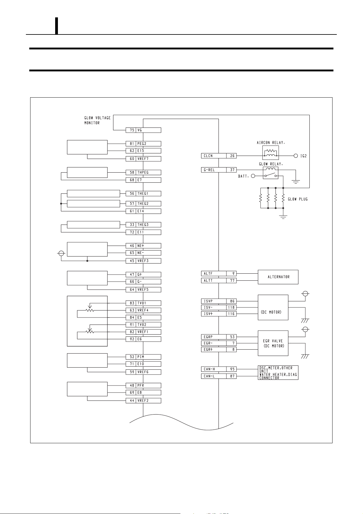
1–33
Operation Section
9. EXTERNAL WIRING DIAGRAM
9.1 Engine ECU External Wiring Diagram (Model Name: MAZDA 5)
Differential
pressure sensor
Engine compartment
temperature sensor
Exhaust temperature sensor 1
Exhaust temperature sensor 2
Exhaust temperature sensor 3
Crankshaft
position sensor
Cylinder
recognition sensor
Accelerator position
sensor
Turbo pressure sensor
Rail pressure sensor
Engine
ECU
Electronic
control throttle
Q001181E
Page 37
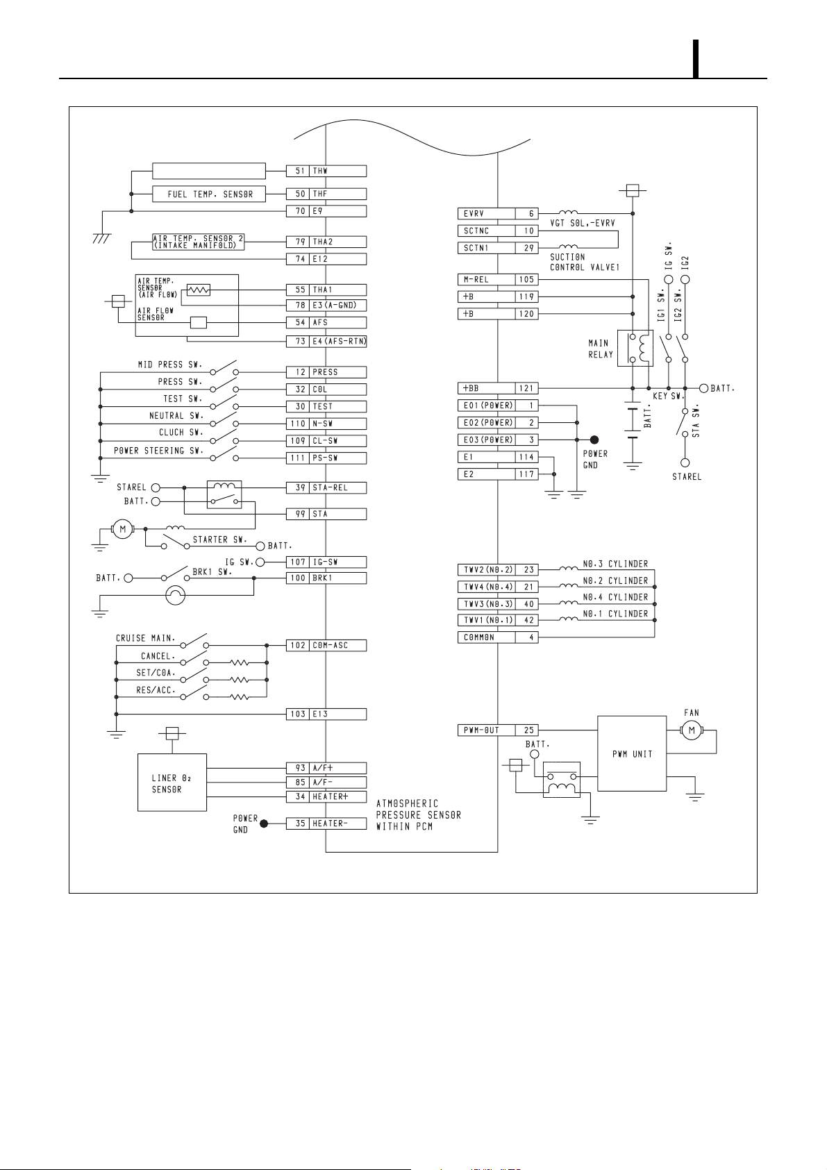
Coolant temperature sensor
Operation Section
1–34
Engine
ECU
Q001182E
Page 38
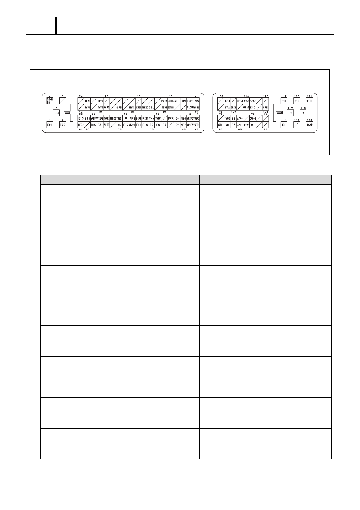
1–35
Operation Section
(1) Connector Diagram
Connector Pin Layout
Terminal Connections (1)
No. Pin Symbol Signal Name No. Pin Symbol Signal Name
1 E01 Power GND 26 CLCN Air Conditioner Relay Actuation Output
2 E02 Power GND 27
—
Q001136E
3 E03 Power GND 28 —
4 COMMON Injection Common 29 SCTN1 Suction Control Solenoid Actuation Out-
put 1
5
6 EVRV VGT Solenoid (E-VRV) Actuation Output 31
7 EGR- EGR-DC Motor Actuation (-) 32 COL Air Conditioning Switch Input
8 EGR+ EGR-DC Motor Actuation (+) 33 THEG3 Exhaust Temperature Sensor 3
9 ALTF Alternator Field Coil Excitation 34 HEATER+ A/F Heater Actuation (+)
10 SCTNC Suction Control Solenoid Actuation Out-
11
12 PRESS Press Switch Input 37 G-REL Glow Plug Relay Actuation Output
13
14 — 39 STA-REL Starter Permission Relay Actuation Output
15
16
17 — 42 TWV1 Injection Drive 1
18
19 — 44 VREF2 Sensor 5V Power Supply
— 30 TEST Test Switch Input
—
35 HEATER- A/F Heater Actuation (-)
put Common
— 36 —
— 38 —
— 40 TWV3 Injection Drive 3
— 41 —
— 43 —
20
21 TWV4 Injection Drive 4 46 NE+ Crankshaft Position Sensor Input (+)
22
23 TWV2 Injection Drive 2 48 PFR Rail Pressure Sensor Input
24
25 PWM-OUT PWM Electric Fan Actuation Output 50 THF Fuel Temperature Sensor Input
— 45 VREF3 Sensor 5V Power Supply
— 47 G+ Cylinder Recognition Sensor Input (+)
— 49 —
Page 39
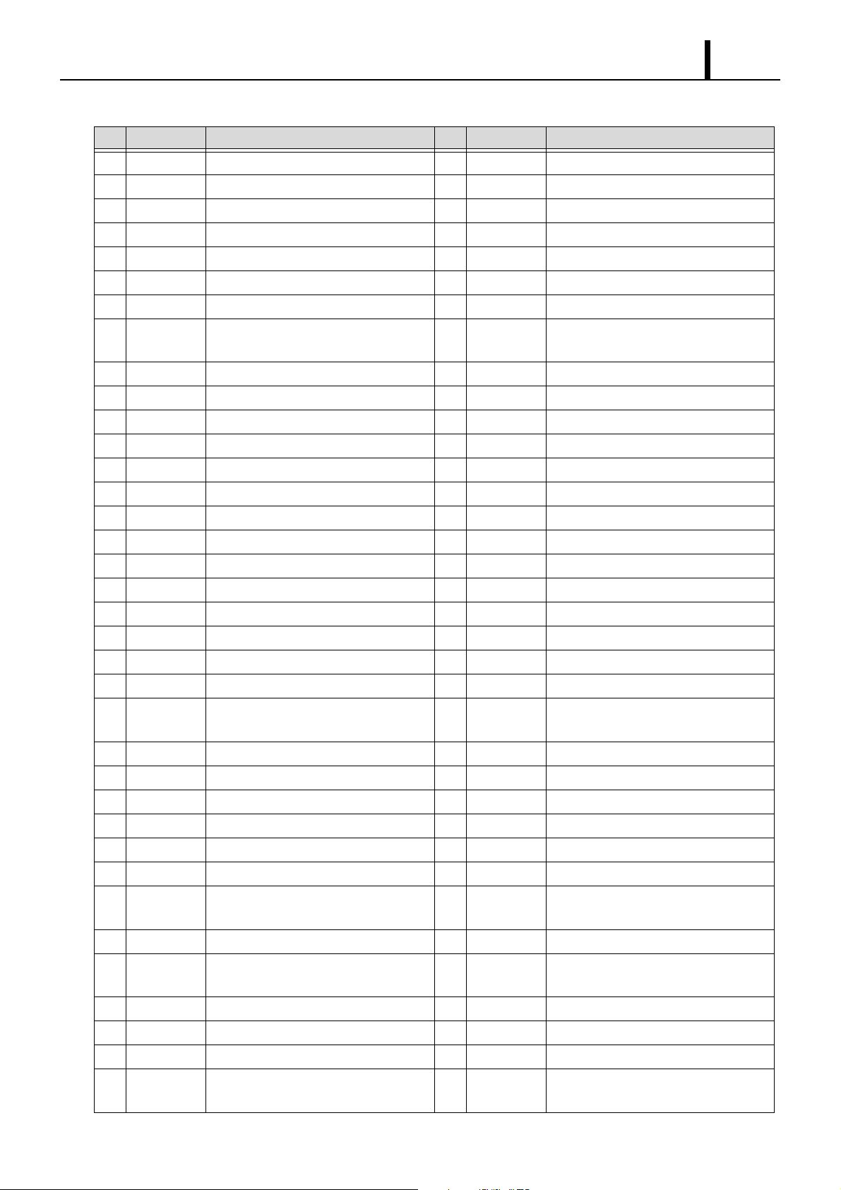
Operation Section
Terminal Connections (2)
No. Pin Symbol Signal Name No. Pin Symbol Signal Name
51 THW Coolant Temperature Sensor Input 87 CAN-L CAN Communication Line (L)
52 PIM Turbo Pressure Sensor Input 88 —
53 EGRP EGR Position Sensor 89 —
54 AFS Mass Air Flow Sensor Input 90 —
55 THA1 Intake Air Temperature Sensor Input 1 91 TVO2 Accelerator Sensor Input 2
56 THEG1 Exhaust Temperature Sensor 1 92 E6 Sensor System Ground
57 THEG2 Exhaust Temperature Sensor 2 93 A/F+ A/F Sensor Input (+)
58 THPEG Engine compartment Temperature Com-
pensation Sensor
59 VREF6 Sensor 5V Power Supply 95 CAN-H CAN Communication Line (H)
94
—
1–36
60 VREF7 Sensor 5V Power Supply 96
61 E14 Sensor System Ground 97 —
62 E15 Sensor System Ground 98 —
63 VREF4 Sensor 5V Power Supply 99 STA Starter Switch Input
64 VREF5 Sensor 5V Power Supply 100 BRK1 Brake Switch Input 1
65 NE- Crankshaft Position Sensor Input (-) 101
66 G- Cylinder Recognition Sensor Input (-) 102 COM-ASC Cruise Control Switch
67
68 E7 Sensor System Ground 104
69 E8 Sensor System Ground 105 M-REL Main Relay Actuation Output
70 E9 Sensor System Ground 106
71 E10 Sensor System Ground 107 IG-SW Ignition SW
72 E11 Sensor System Ground 108
73 E4 (AFS-
74 E12 Sensor System Ground 110 N-SW Neutral Switch Input
75 VG Glow Plug Voltage Monitor 111 PS-SW Power Switch
76
77 ALTT Alternator Power Generation Detector 113 —
— 103 E13 Sensor System Ground
RTN )
Mass Air Flow Sensor Special Use
Ground
109 CL-SW Clutch Switch Input
— 112 —
—
—
—
—
—
78 E3 Sensor System Ground 114 E1 Signal Ground
79 THA2 Intake Air Temperature Sensor Input 2 115
80 — 116 ISV+ Electronic Control Throttle DC Motor
81 PEG2 Exhaust Pressure Sensor Input 2 117 E2 Signal Ground
82 VREF1 Sensor 5V Power Supply 118 ISV- Electronic Control Throttle DC Motor
83 TVO1 Accelerator Sensor Input 1 119 +B +B Power Supply (M-REL Downstream)
84 E5 Sensor System Ground 120 +B +B Power Supply (M-REL Downstream)
85 A/F- A/F Sensor Input (-) 121 +BB Battery Power Supply
86 ISVP Electronic Control Throttle Position Sen-
sor Input
——
—
Actuation (+)
Actuation (-)
Page 40
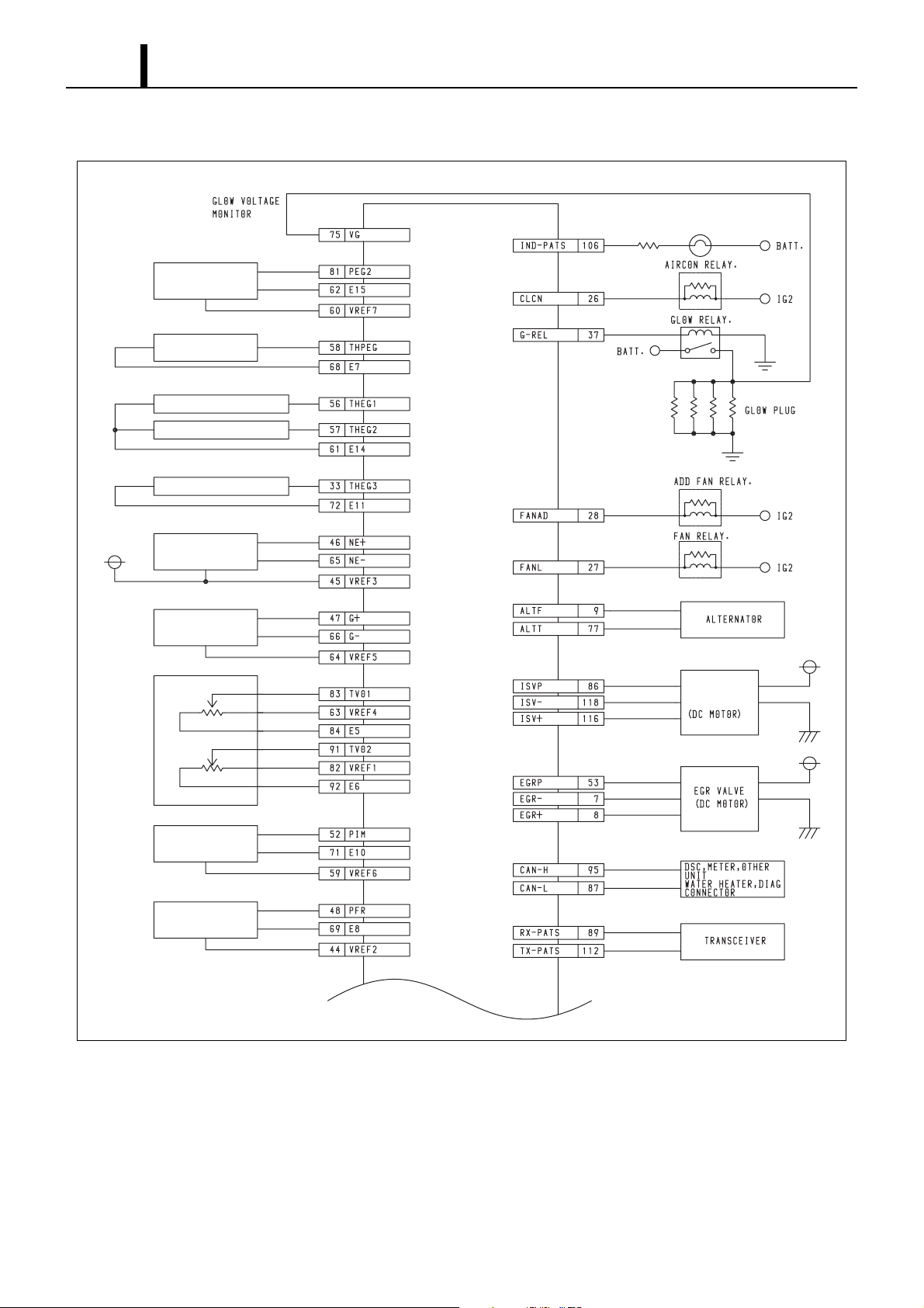
1–37
Operation Section
9.2 Engine ECU External Wiring Diagram (Model Name: MAZDA 6)
Differential
pressure sensor
Engine compartment
temperature sensor
Exhaust temperature sensor 1
Exhaust temperature sensor 2
Exhaust temperature sensor 3
Crankshaft
position sensor
Cylinder recognition
sensor
Accelerator Position
Sensor
Turbo pressure sensor
Rail pressure sensor
Engine
ECU
Electronic
control throttle
Q001183E
Page 41
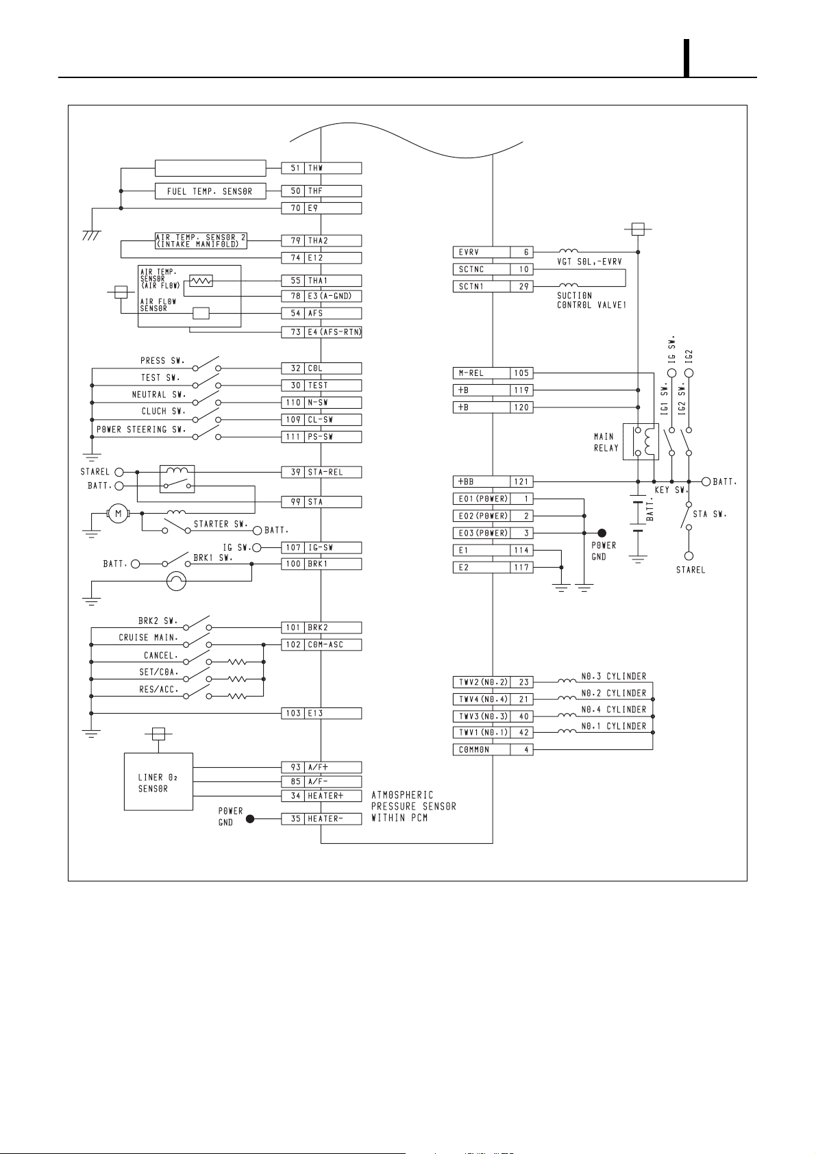
Coolant temperature sensor
Operation Section
1–38
Engine
ECU
Q001184E
Page 42
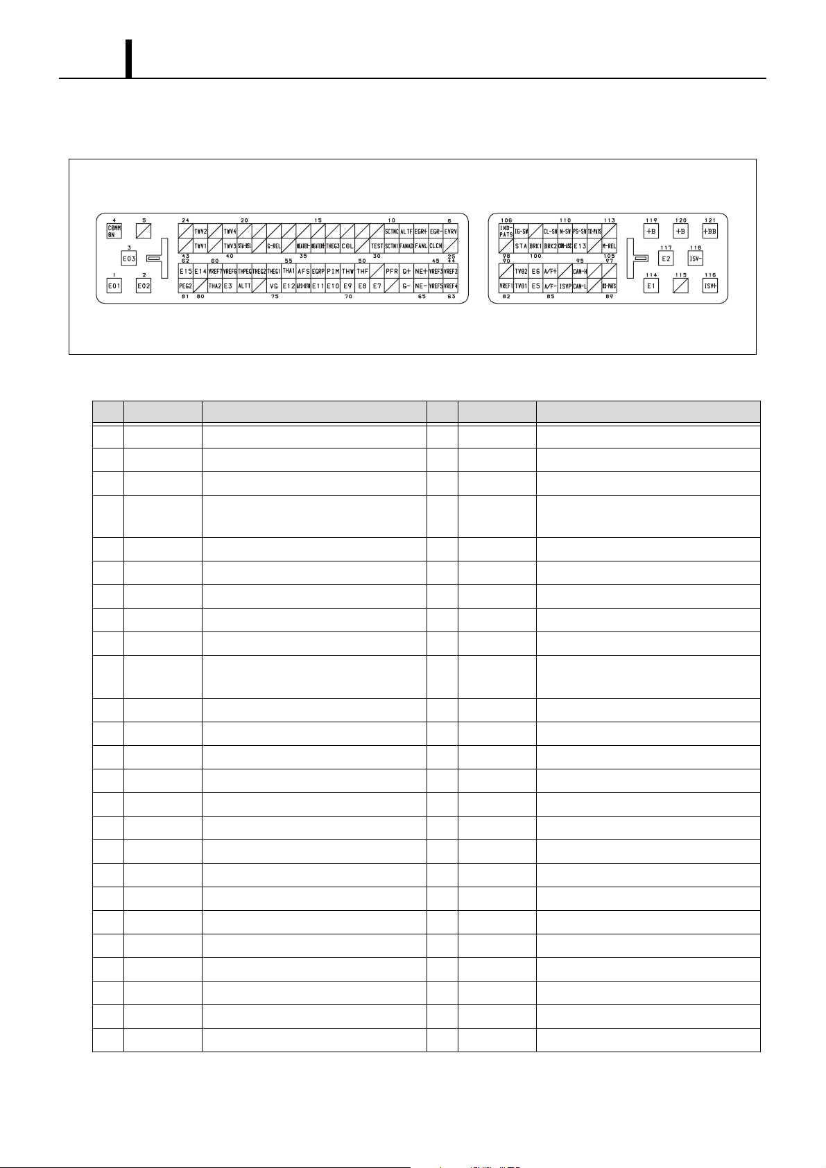
1–39
Operation Section
(1) Connector Diagram
Connector Pin Layout
Terminal Connections (1)
No. Pin Symbol Signal Name No. Pin Symbol Signal Name
1 E01 Power GND 26 CLCN Air Conditioner Relay Actuation Output
2 E02 Power GND 27 FANL Fan Relay (Low) Actuation Output
Q001137E
3 E03 Power GND 28 FANAD ADD Fan Relay Actuation Output
4 COMMON Injection Common 29 SCTN1 Suction Control Solenoid Actuation Out-
put 1
5 — 30 TEST Test Switch Input
6 EVRV VGT Solenoid (E-VRV) Actuation Output 31
7 EGR- EGR-DC Motor Actuation (-) 32 COL Air Conditioning Switch Input
8 EGR+ EGR-DC Motor Actuation (+) 33 THEG3 Exhaust Temperature Sensor 3
9 ALTF Alternator Field Coil Excitation 34 HEATER+ A/F Heater Actuation (+)
10 SCTNC Suction Control Solenoid Actuation Out-
put Common
11
12 — 37 G-REL Glow Plug Relay Actuation Output
13
14 — 39 STA-REL Starter Permission Relay Actuation Output
15
16
17 — 42 TWV1 Injection Drive 1
18
19 — 44 VREF2 Sensor 5V Power Supply
— 36 —
— 38 —
— 40 TWV3 Injection Drive 3
— 41 —
— 43 —
35 HEATER- A/F Heater Actuation (-)
—
20
21 TWV4 Injection Drive 4 46 NE+ Crankshaft Position Sensor Input (+)
22
23 TWV2 Injection Drive 2 48 PFR Rail Pressure Sensor Input
24
25 — 50 THF Fuel Temperature Sensor Input
— 45 VREF3 Sensor 5V Power Supply
— 47 G+ Cylinder recognition Sensor Input (+)
— 49 —
Page 43
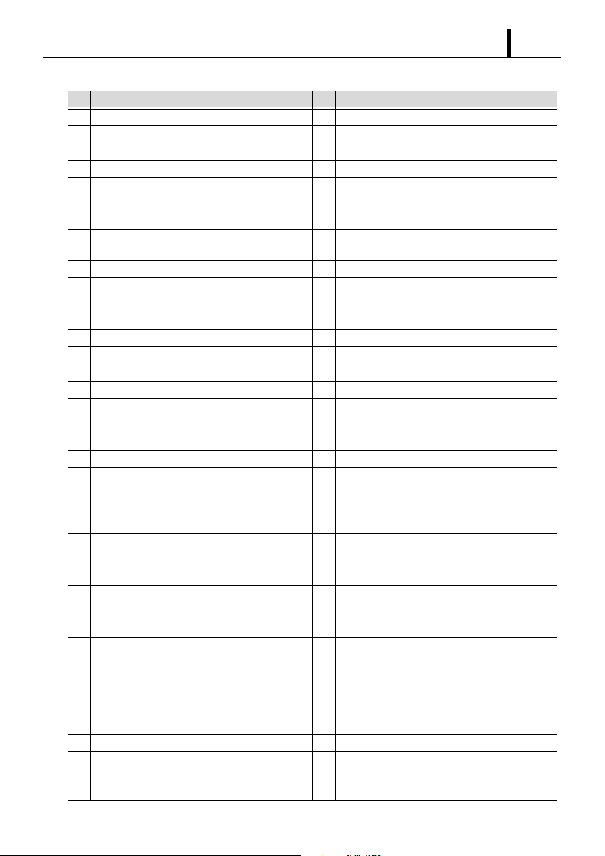
Operation Section
Terminal Connections (2)
No. Pin Symbol Signal Name No. Pin Symbol Signal Name
51 THW Coolant Temperature Sensor Input 87 CAN-L CAN Communication Line (L)
52 PIM Turbo Pressure Sensor Input 88 —
53 EGRP EGR Position Sensor 89 RX-PATS PATS Communication (Receiving)
1–40
54 AFS Mass Air Flow Sensor Input 90
55 THA1 Intake Air Temperature Sensor Input 1 91 TVO2 Accelerator Sensor Input 2
56 THEG1 Exhaust Temperature Sensor 1 92 E6 Sensor System Ground
57 THEG2 Exhaust Temperature Sensor 2 93 A/F+ A/F Sensor Input (+)
58 THPEG Engine compartment Temperature Com-
pensation Sensor
59 VREF6 Sensor 5V Power Supply 95 CAN-H CAN Communication Line (H)
60 VREF7 Sensor 5V Power Supply 96
61 E14 Sensor System Ground 97 —
62 E15 Sensor System Ground 98 —
63 VREF4 Sensor 5V Power Supply 99 STA Starter Switch Input
64 VREF5 Sensor 5V Power Supply 100 BRK1 Brake Switch Input 1
65 NE- Crankshaft Position Sensor Input (-) 101 BRK2 Brake Switch Input 2
66 G- Cylinder recognition Sensor Input (-) 102 COM-ASC Cruise Control Switch
67
68 E7 Sensor System Ground 104
69 E8 Sensor System Ground 105 M-REL Main Relay Actuation Output
70 E9 Sensor System Ground 106 IND-PATS Antitheft Indicator
71 E10 Sensor System Ground 107 IG-SW Ignition SW
— 103 E13 Sensor System Ground
94
—
—
—
—
72 E11 Sensor System Ground 108
73 E4 (AFS-
RTN )
74 E12 Sensor System Ground 110 N-SW Neutral Switch Input
75 VG Glow Plug Voltage Monitor 111 PS-SW Power Switch
76
77 ALTT Alternator Power Generation Detector 113
78 E3 Sensor System Ground 114 E1 Signal Ground
79 THA2 Intake Air Temperature Sensor Input 2 115
80 — 116 ISV+ Electronic Control Throttle DC Motor
81 PEG2 Exhaust Pressure Sensor Input 2 117 E2 Signal Ground
82 VREF1 Sensor 5V Power Supply 118 ISV- Electronic Control Throttle DC Motor
83 TVO1 Accelerator Sensor Input 1 119 +B +B Power Supply (M-REL Downstream)
84 E5 Sensor System Ground 120 +B +B Power Supply (M-REL Downstream)
85 A/F- A/F Sensor Input (-) 121 +BB Battery Power Supply
86 ISVP Electronic Control Throttle Position Sen-
— 112 TX-PATS PATS Communication (Sending)
Mass Air Flow Sensor Special Use
Ground
sor Input
109 CL-SW Clutch Switch Input
——
—
—
—
Actuation (+)
Actuation (-)
Page 44

1–41
Operation Section
Page 45

Published : June 2005
Edited and published by:
DENSO CORPORATION
Service Department
1-1 Showa-cho, Kariya, Aichi Prefecture, Japan
 Loading...