

Page 1
Installation Instructions
Models: SESD180, DESD180
1/4" Semi-Frameless Door and 3/8" In-Line Panel
Scan this Barcode for Parts Bag BP.3143.NLT
Thank you for purchasing this outstanding product!
This booklet will help you install your units safely and successfully.
IMPORTANT: Warnings and General Shower Door Information
Page 2
SAFETY
WARNINGS:
GLASS FRAGILESHARPCAUTIONHEAVY
P/N MM.5023
rev061818
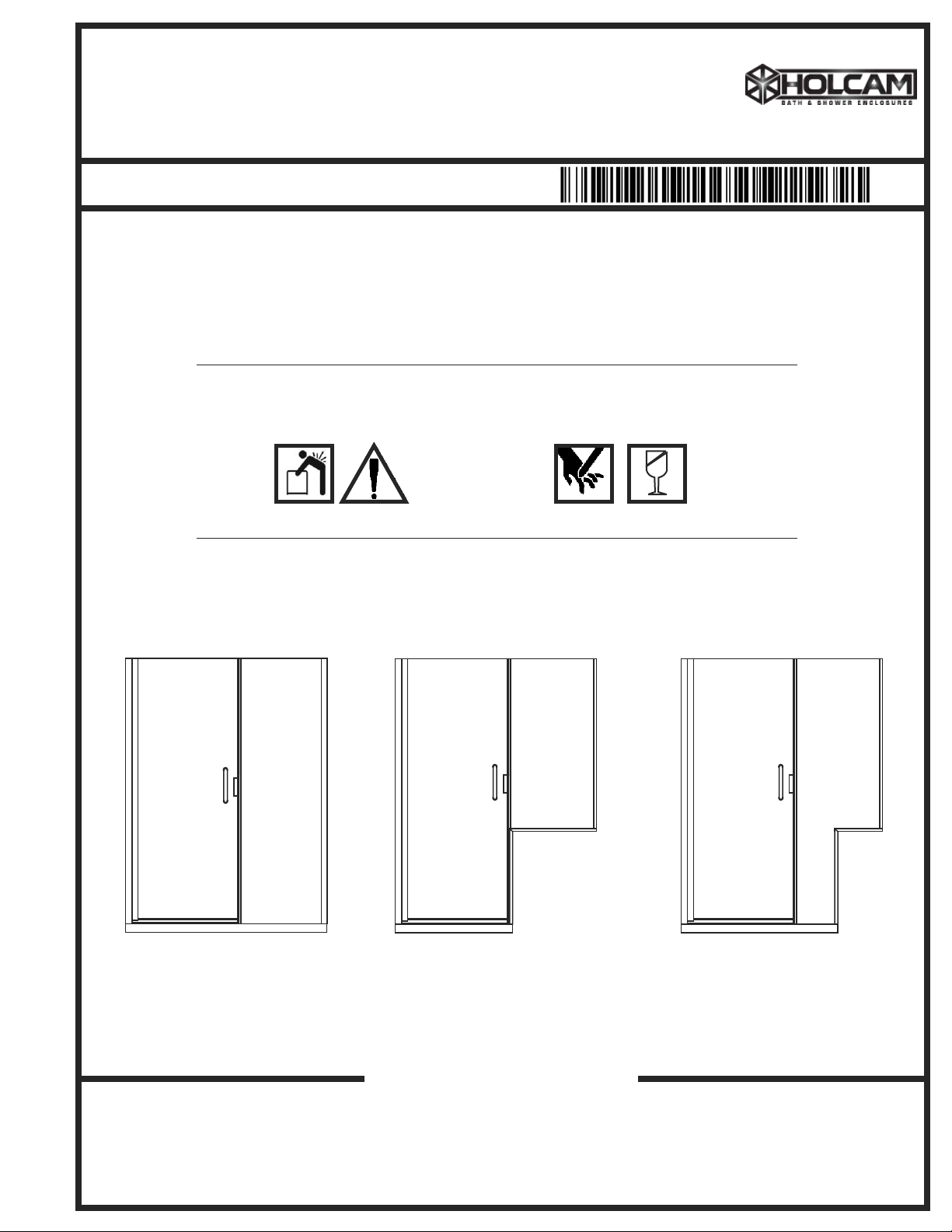
Pick a unit below that best represents your configuration.
SESD180
DESD180
Standard Door/Panel
Pages 3 - 5
* Pencil or water soluble felt pen
* Hacksaw with 24 tooth blade
* Metal file (smooth sharp edges)
* Tape measure
* Drill, electric or battery
SESD180
DESD180
with buttress
Pages 6 - 8
General Required Tools
* #2 Phillips Screw driver
* 7/64” and 3/16” drill bits
* Caulking gun
* Clear 100% Silicone
(recommended)
SESD180
DESD180
with notched panel
Pages 9 - 11
* 4 ft. Level
* Rubber mallet
* Razor knife
* Blue painters tape
Page 2
SAFETY
WARNINGS:
GLASS FRAGILESHARPCAUTIONHEAVY
CAUTION - READ THOROUGHLY BEFORE INSTALLATION
Follow instructions: Instructions must be read and followed carefully to reduce the risk of
serious injury during and after installation. Any deviation from these instructions can create
safety hazards.
Tempered Glass: Agalite enclosures glass panels are safety tempered to conform to general
building codes. The intent of tempering is to reduce the risk of injury. Be careful handling
tempered glass. Pay special attention to protect all edges of the glass from contact with hard
surfaces.
General Notes:
- Exposed ends of aluminum and other hard components can be rough, sharp or jagged due to
the processes of cutting, drilling, notching, etc. Sharp ends must be deburred, smoothed or rounded
by the installer before installation. Failure to do so could result in serious injury to installer and user of
the enclosure.
- Sliding and swinging glass doors hitting any unprotected bathroom obstruction or metal or
glass component of the shower door itself, may indicate improper installation and could lead to glass
breakage or serious injury. The installer must correct the deficiencies before allowing the door to be
used.
- Towel Bars, handles and other accessories are in no way considered to be grab bars or other
bracing or fall prevention mechanisms. The intent of these accessories is to facilitate proper
operations and esthetics of the unit.
Shower Door Facts
Shower Doors are Not Watertight: Depending on the type of shower door selected, a properly
designed and installed shower enclosures will protect areas outside of the enclosure from water
damage under normal shower conditions to varying degrees. Excessive water pressure or directing
the shower head or hand held sprays directly at doors or joints is not a normal shower conditions and
can result a leak. The amount of water that can escape your shower varies by the type of shower as
well. Heavy glass units with no or limited vinyl seals will allow water to escape under normal
conditions. In general, the more metal and seals in the unit, the more water protection will be
achieved.
Drilling holes in horizontal surfaces: Drilling holes to anchor horizontal sills and curbs to
thresholds and tub decks is discouraged. Using masking tape or double-sided tapes to secure nonload bearing components during installation (permanently secured later with silicone/caulking) is one
technique to help minimize potential of water leaking underneath flooring. These instructions do not
recommend drilling holes on horizontal surfaces for this reason.
Metal Colors:
- Anodized Aluminum: The color of anodized Silver, Brushed Nickel, Satin Silver, Dark Bronze,
and Gold anodized aluminum will vary between adjacent components because of variability's within
polishing, anodizing process and alloy composition. We make every effort to limit the variation; but, it
is allowable and must be accepted.
- Electro Plated Brass and Stainless Steel: The color of Silver, Brushed Nickel, Satin Silver, Oil
Rubbed Bronze, Dark Bronze, and Gold electro plated components will also vary. This is allowable.
Most of these finishes are also “living finishes”, meaning, they may change, wear, weather, show
patina, oxidize, etc. over the life of the product. This is allowable.
- Powder Coat: This is a painting process and therefore can achieve the best color matching.
Power coat paint, however, is less durable at joints of moving components and at edges that have
been cut after the powder coat has cured. Some flaking or chipping in these areas are allowable.
- All Metal: Any metal component (and glass components as well) will have limited scratches and
pits. We make every effort to limit them; but, they are allowable and must be accepted.
Cleaning and Care: refer to your owners manual for cleaning and care instructions.
Page 2
Page 3
Installation Instructions
Models: SESD180, DESD180
1/4" Semi-Frameless Door and 3/8" In-Line Panel
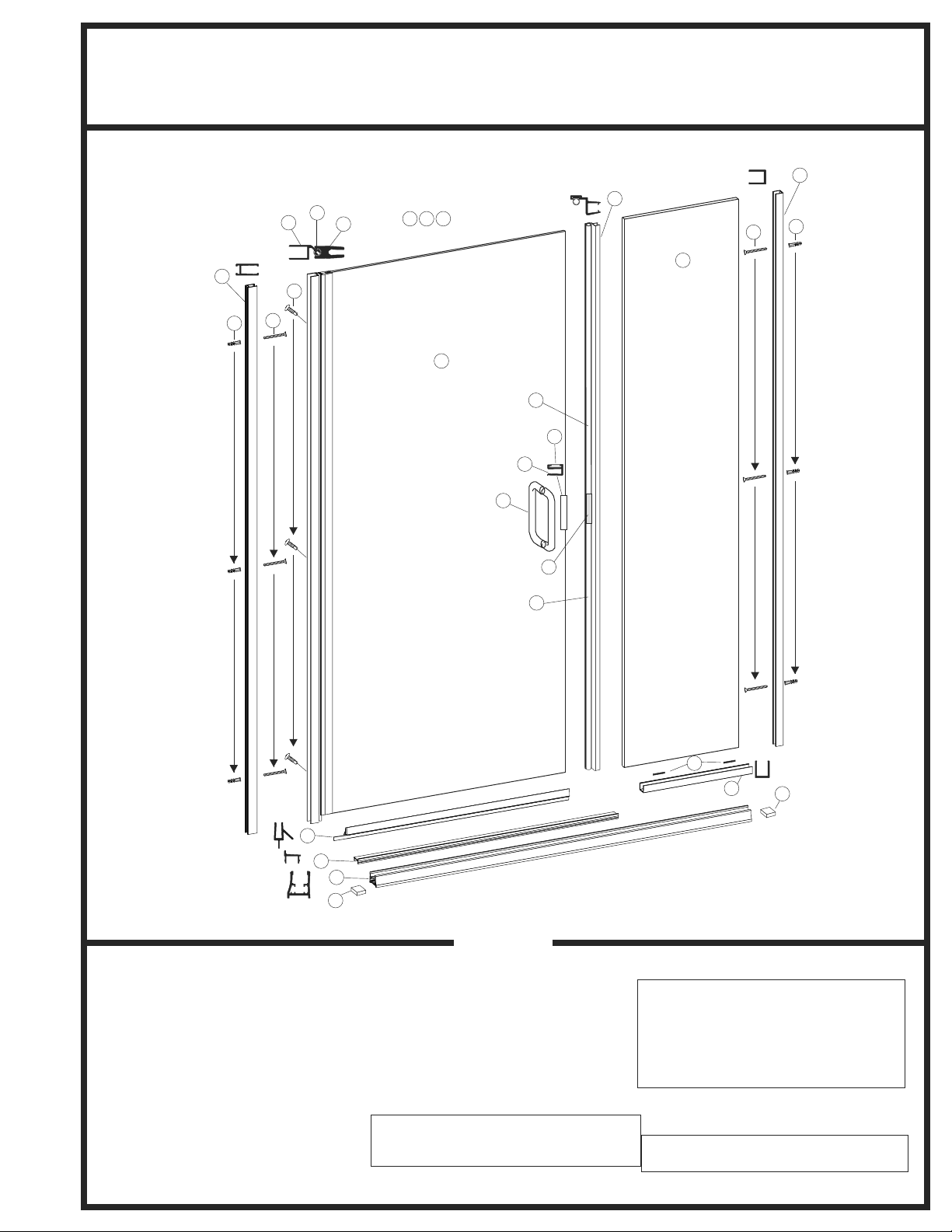
Figure 1 - Exploded View
10
9
3
20
22
19
11
12
14
13
Not Shown
15
7
24
23
18
8
7
6
19
16
4
20
17
2
1
21
1. EX.1022 - Stall Curb - 1
2. EX.1025 - Curb Filer - 1
3. EX.1268 - Hinge Wall Channel - 1
4. EX.1018 - Panel Wall Channel - 1
5. EX.1018 - Panel Sill - 1
6.- 8. Clear-Poly Latch Assembly
9. - 15. Door Assembly - 1
16. 3/8 Clear Fixed Panel - 1
17. VN.4062 - PVC Drip Deflector - 1
18. HA.2701 - D-pull Handle - 1
19. SP.2101 - #8 X 1-1/2 FHPHSMS - 6
20. SP.2217 - 3/16 X 7/8 Wall Anchor - 6
Parts List
21. SP.2204 - Foam Plug - 2
22. SP.2110 - #8 X 1/2 PHPH TEK - 3
23. - 24. Magnetic Edge Cap Assembly -1
25. BP.3028 - Setting Block Kit
26. SP.2221 - Centering Clip -5
27. VN.4033 - VS-20 Dry Glaze Vinyl
Extra screws may be provided
for your convenience
6. Clear Poly Latch-VN.4075-PVC Latch - 1
7. VN.4002 - Bulb Seal - 1
8. SP.2194 - Strike Plate - 1
25
5
21
9. Door Assembly-EX.1165-Hinge Jamb-1
10. VN.4034 - Hinge Sleeve - 1
11. EX.1466 - Hinge Rail - 1
12. SP.2200 - Hinge Pin - 2
13. SP.2181 - Flat Washer - 2
14. SP.2123 - #6 X 1/2 PHPH MS - 2
15. 1/4 Clear Door Glass - 1
Boxed information is assembly detail.
23. Magnetic Cap Assy-EX.1619- Catch - 1
24. SP.2191 - Magnet - 1
Page 3
Page 4
Installation Instructions
Models: SESD180, DESD180
1/4" Semi-Frameless Door and 3/8" In-Line Panel
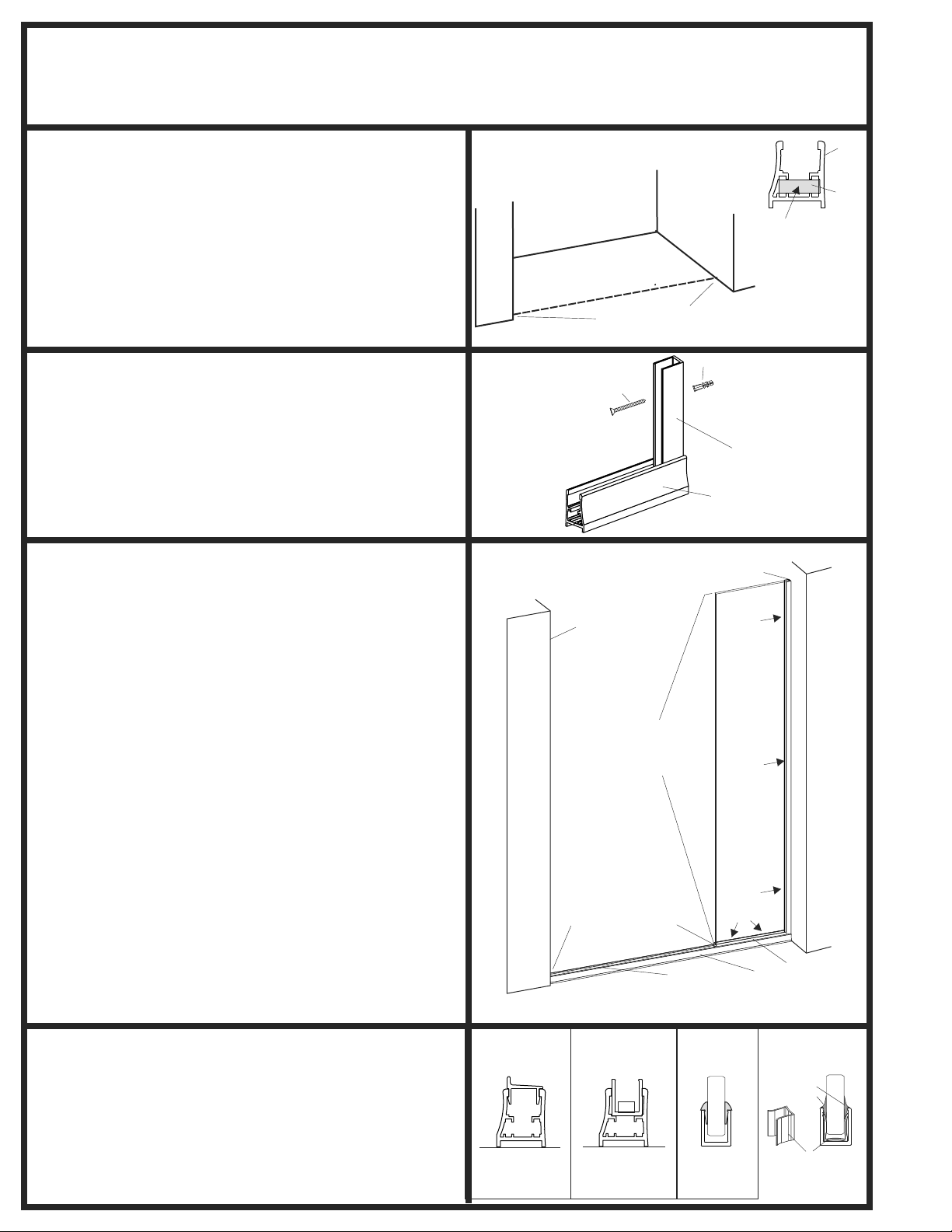
STEP 1 - Curb Installation (#1)
* Measure the wall to wall where you want the center of
the unit to be installed, subtract 1/16" from this.
* Mark location for reference.
* Cut the Stall Curb #1 to this length.
* Insert foam plug #21 into each end of the Stall Curb
and recess 1/8".
* Fill 1/8” void with silicone.
* Set the curb in place centered over where you measured,
secure with blue tape.
* Orient weep holes are to inside of shower.
* Do not screw the curb to threshold.
STEP 2 - Wall Channel (#4)
* Insert Wall Channel #4 into curb, on side of fixed panel.
* Plumb channel with a level.
* Mark the hole locations onto the wall.
* Remove the channel
* Drill marked locations with 3/16" drill bit
* Insert 3 - Wall Anchors #20 (may have to razor heads of
anchors flush to wall).
* Re-insert channel and secure with 3 - #19 screws.
STEP 3 - Panel Sill (#5) and 3/8” Fixed Panel (#16)
* Measure width of 3/8” Fixed Panel and subtract 3/8”.
* Cut the Panel Sill #5, to this length.
* Set the Panel Sill #5 into the Stall Curb #1 and butt to
the Wall Channel #4.
* Insert two Setting Blocks #25 into Panel Sill.
Measure and then subtract 1/16"
Mark location for reference
#20
#19
(X3)
*Your installation may
be reversed
Door-Side
Wall
#1
#21
Fill void with silicone.
Push towards walls
after curb is set in place.
#4
#1 (outside
of unit)
#4
#26
Wet Glaze Option Only - If using silicone to bond the
glass to the wall channel and sill:
- Install 2 - #26 Centering Clips evenly spaced
into Panel Sill, offset from Setting Blocks.
- Insert 3 - #26 Centering Clips into the Wall channel.
Dry Glaze Option - If using push-in glazing vinyl to set
the 3/8” glass panel, do not use Centering Clips #26.
* Set 3/8” Glass Panel into Panel Sill and Wall Channel.
* Flush glass edge to exposed end of Panel Sill #5.
* Adjust top of glass flush to top of Wall Channel, place
additional setting blocks under glass if needed.
* Ensure vertical edge of 3/8” Glass Panel is plumb.
Wet Glaze Option - Temporarily, but securely fix Glass
Panel into position with blue painter’s tape.
Dry Glaze Option - Holding the glass panel in position,
roll or press the Glazing Bead into both sides of sill and
wall channel using a roller or smooth block of wood.
* Check to ensure panel didn’t move.
STEP 4 - Curb Filler (#2)
* Measure from the edge of the 3/8” Glass Panel to the
Door side wall.
* Cut the Curb Filler #2 to this length.
* With the two forks pointing down and the vertical leg to
the front of the unit, snap the Curb Filler into the Stall
Curb.
* The slope of the Curb filler should be to the inside of the
shower.
Page 4
#16
Step 5
Measure then
cut Clear-Poly
Latch #6
#26
#26
Measure then
#26
cut curb filler #2
#5
#27
#1
Silicone
Bead
#26
Wet Glazing
parts detail
#2
*** If using the Dry Seal, once the push in vinyl has been installed, it
cannot be easily removed without being replaced.
Outside
#2 / #1
Cross-section
Outside
#5 / #1
Cross-section
w/ setting block
Dry Glaze
Glazing Bead
Page 5
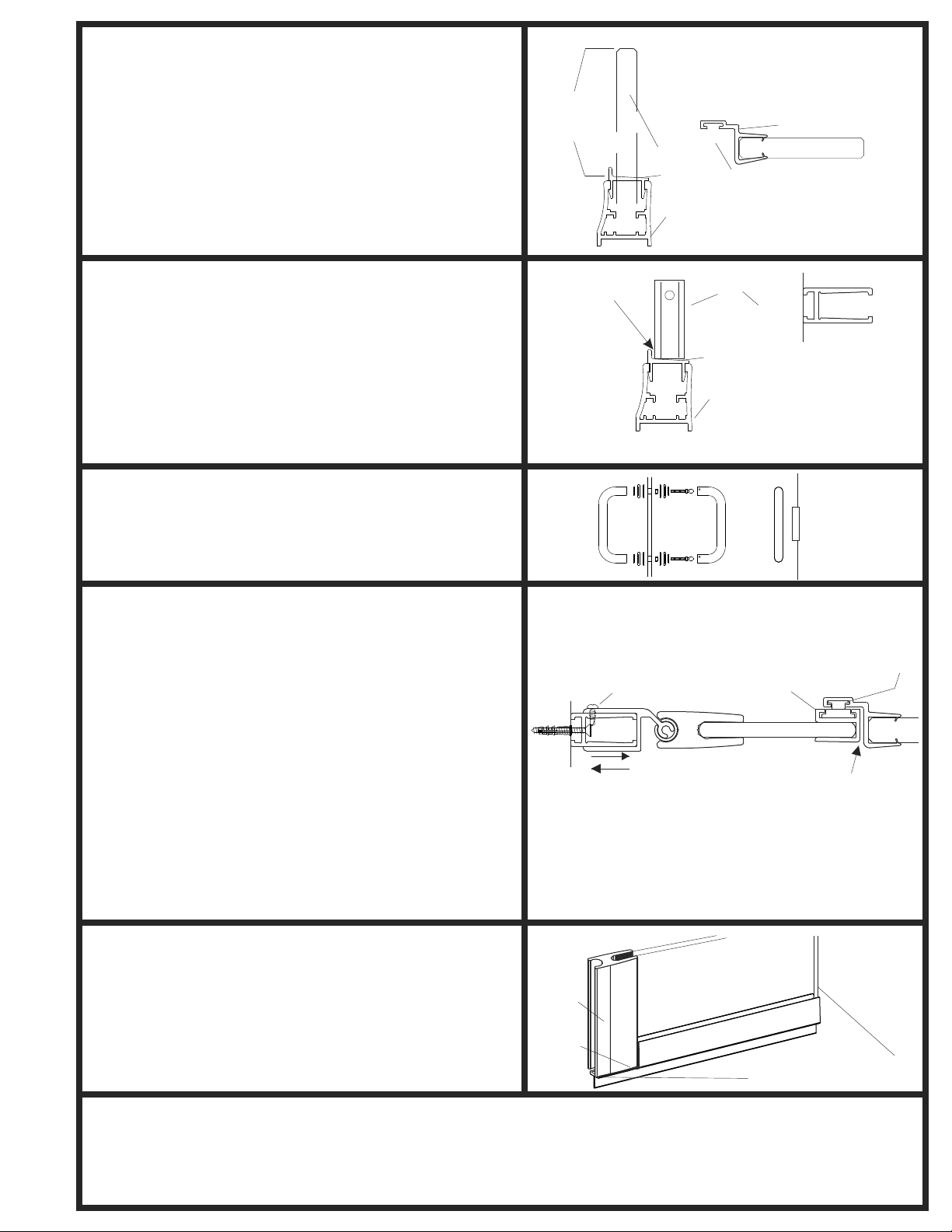
STEP 5 - Clear-Poly Latch Jamb (#6)
* Measure from top of 3/8” Glass Panel #16 to top of the
sloped surface of the Curb Filler #2.
* Take Clear-Poly Latch Jamb assembly, and remove the
Bulb Seal and Strike Plate, set aside for later step.
* Cut Clear-Poly Latch #6 to above dimension using a 24
tooth hatch-saw. Power saw may damage latch.
Recommended: notch the Clear-Poly Latch at bottom to
clear the Panel Sill #5 (trim legs up 3/16”).
* Apply the Clear-Poly Latch Jamb on edge of Glass with
latch inside unit ensuring it is flush with the top of the
Fixed panel.
STEP 6 - Attach Door-Side Wall Channel (#3)
* Set door-side Wall Channel #3 in place against the
door side wall, on top of the Curb Filler.
* Gap the bottom of the wall channel 1/16" from the
vertical water dam of the Curb Filler (This will allow
the room for the Door assembly to slide over.)
* Plumb Wall Channel, mark the hole locations on wall
and remove Wall Channel.
* Drill holes with 3/16" bit, insert 3 - #20 Wall Anchors,
re-install Wall channel and secure with 3 - #19 Screws.
Measure
(see previous
figure too)
Outside
1/16" Gap
Outside
#16
#2
#1
#6
#7, #8 (not shown)
outside of unit
#3#3
Side
#2
#1
Top View
Wall
against
STEP 7 - Door Assembly / Pre-Hanging Prep
* Attach Pull - Handle #18 to Door.
* Dry run the position of Magnetic Catch Assembly, #23,
#24 and mark location with marker on glass.
* Apply small bead of silicone inside Catch Assembly
and work onto edge of glass at mark. Let silicone dry.
STEP 8 - Hang Door Assembly
* Slide door assembly over the Wall Channel (Step 6).
* Adjust door until top edge of the door is level and flush
with top of 3/8” Glass Panel.
* Also ensure door-to-latch gap is consistent from
bottom to top.
* When aligned, secure Door Assembly to Wall Channel
with 3 - #22 screws using factory pilot holes in the
Hinge Jamb.
Finish Latch
* Temporarily slide Strike Plate #8 into Clear-Poly Latch
#6, align with Mag Catch #23.
* Mark top and bottom of Strike Plate onto Latch.
* Marks and cut Bulb Seal #7 to proper length.
* From top of latch, re-insert bottom bulb seal, strike and
top seal. Dabs of silicone may be required to secure
Bulb Seals and Strike in place. Hold with Painters
tape while drying.
#18
Style Washers
are Optional
S
ecure with
3 - screws
Slide door
over wall channel
Inside
Handle
Magnet Catch
centered on
handle
Strike Plate #8
Magnetic Catch #23
Door-to-Latch
Gap (1/16” to 1/8”)
STEP 8 - Bottom Sweep Fitting (#17)
* Measure the Door Glass including Hinge Rail.
* Subtract 1/16" and cut the Bottom sweep to this length.
IMPORTANT: The sweep is notch on both ends. You
must leave the notch that goes under the Hinge Rail
Hinge
Rail
Drip Deflector
on inside
for your door. Cut off the end with the notch you don't
need.
* Trim the inside deflector 3/8" so it will clear the
Latch Jamb when door is closed.
Notched
Side
Measure from edge of glass
to outside of hinge rail
STEP 10 - Final Sealing / Siliconing the Unit (let dry for 24 hours before use)
* On the outside of the unit, run a bead of silicone down both walls and across the bottom where the metal meets
the walls and base.
* Apply a dab of silicone at the bottom of the latch jamb where it meets the Curb Filler.
Page 5
Page 6
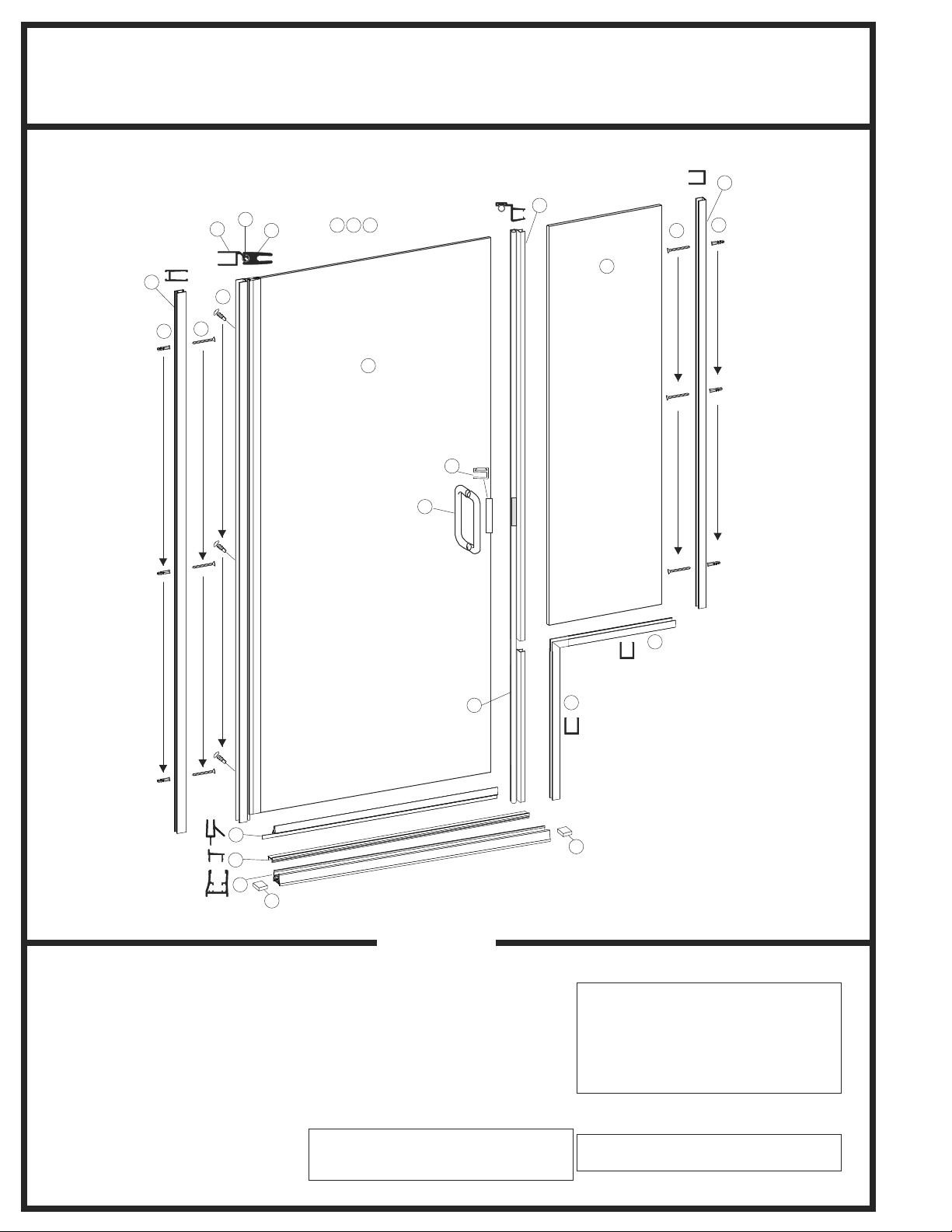
Installation Instructions
Models: SESD180, DESD180 with Buttress
1/4" Semi-Frameless Door and 3/8" In-Line Panel
Figure 1 - Exploded View
12
11
3
22
24
21
13
14
16
15
Not Shown
17
25
20
7
21
18
4
22
19
2
1
1. EX.1022 - Stall Curb - 1
2. EX.1025 - Curb Filler - 1
3. EX.1268 - Hinge Wall Channel - 1
4. EX.1018 - Panel Wall Channel - 1
5. EX.1018 - Panel Sill Horizontal - 1
6. EX.1018 - Panel Sill Vertical - 1
7. - 9. VN.4075 - Clear PVC Latch Assy - 1
10. VN.4076 Buttress PVC Latch Jamb - 1
11. - 17. Door Assembly - 1
18. 3/8 Fixed Panel - 1
19. VN.4062 - PVC Drip Deflector - 1
20. HA.2701 - D-Pull Handle - 1
Page 6
23
Parts List
21. SP.2101 - #8 X 1-1/2 FHPHSMS - 6
22. SP.2217 - 3/16 X 7/8 Wall Anchor - 6
23. SP.2221 - Foam Plug - 2
24. SP.2110 - #8 X 1/2 PHPH TEK - 3
25. - 26. Magnetic Edge Cap Assy - 1
27. BP.3028 - Setting Block Kit - 1
28. SP.2204 - Centering Clip - 5
29. VN.4033 - VS-20 Dry Glaze Vinyl - 3
Extra screws may be provided
for your convenience
7. VN.4075 - Clear PVC Latch Assy - 1
8. VN.4002 - Bulb Seal - 1
9. SP.2194 - Strike Plate - 1
5
10
6
23
11. - 17. Door Assembly EX.1165 - Hinge Jamb - 1
12. VN.4034 - Hinge Sleeve - 1
13. EX.1466 - Hinge Rail - 1
14. SP.2200 - Hinge Pin - 2
15. SP.2181 - Flat Washer - 2
16. SP.2123 - #6 X 1/2 PHPH MS - 2
17. 1/4 Door Glass - 1
Boxed information is assembly detail.
25. Magnetic Cap Assy EX.1619 - Catch - 1
26. SP.2191 - Magnet - 1
Page 7
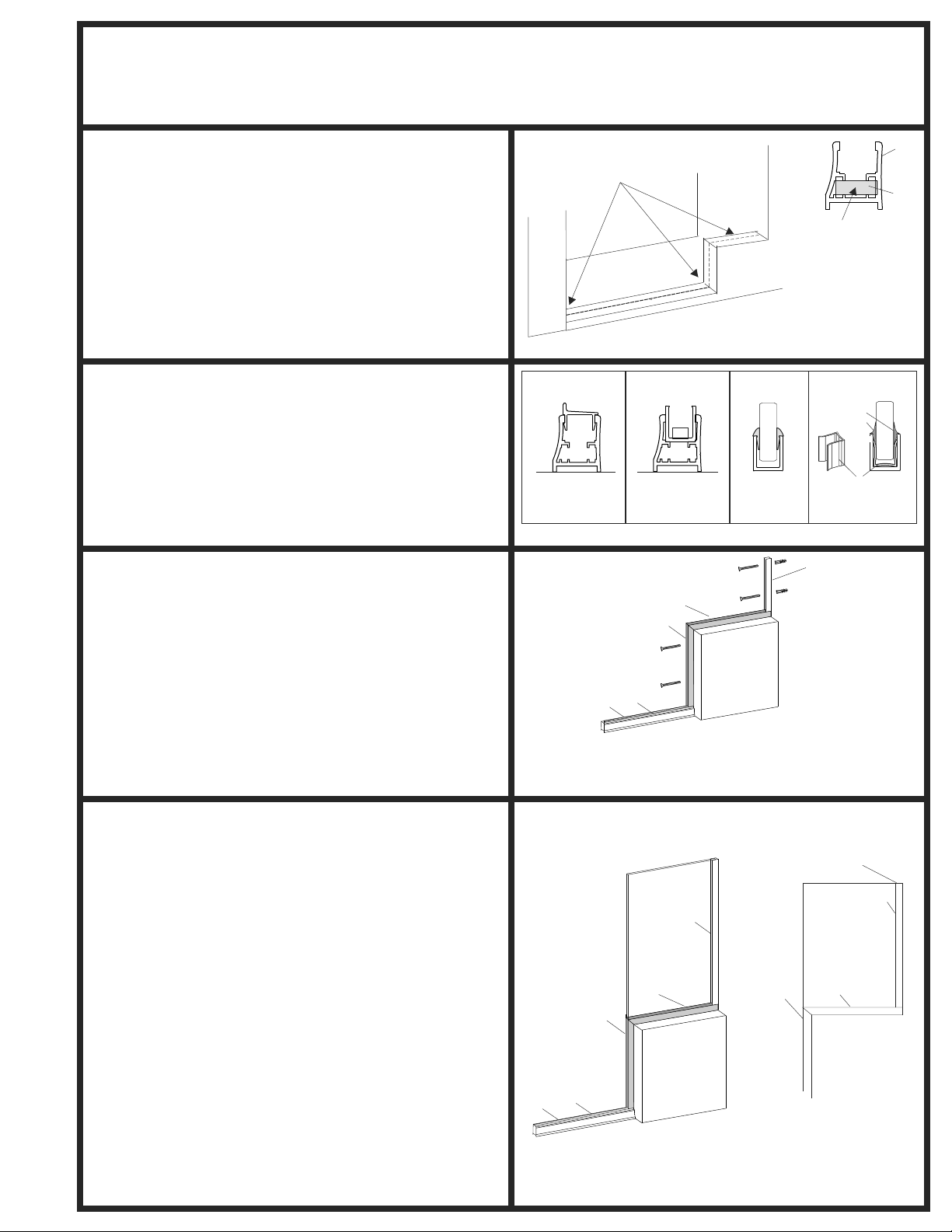
Installation Instructions
Models: SESD180, DESD180 with Buttress
1/4" Semi-Frameless Door and 3/8" In-Line Panel
STEP 1 - Curb Installation (#1)
* Measure the wall to face of buttress wall where you want
the center of the unit to be installed.
* Subtract 1/16" from this. Mark location for reference.
* Cut the Stall Curb #1 to this length.
* Insert foam plug into each end of the Stall Curb.
and recess 1/8"
* Fill 1/8” void with silicone.
* Set the curb in place centered over where you marked.
* Secure with blue tape.
* Weep holes are to inside of shower.
* Do not screw the curb to threshold.
STEP 2 - Curb Filler (#2)
* Measure from the face of the buttress wall to the Door
side wall.
* Cut the Curb Filler #2 to this length.
* With the two forks pointing down and the vertical leg to
the front of the unit, snap the Curb Filler into the Stall
Curb. The slope of the Curb filler should be to the inside
of the shower.
STEP 3 - Wall Channel (#4)
* Set Vert. Wall Channel #6 on top of curb filler #2
on face of buttress and plumb channel with a level.
* Mark the hole locations onto the wall.
* Remove the channel and drill marked locations with
3/16" drill bit.
* Insert 2 - Wall Anchors #22 (may have to razor heads off
anchors flush to wall).
* Re-insert channel and secure with 2 - #21 screws.
* Follow with the Horizontal Channel and tape in place.
* Set Wall Channel #4 on top of the horizontal channel,
plumb with a level. Mark the hole locations onto the wall.
* Drill with a 3/16 bit. Secure with 2 - #21 screws and 3 #22 Wall Anchors.
Mark Centerline
location for reference
Measure
Outside
#2 / #1
Cross-section
Drawing not
proportioned
w/ setting block
(X2)
#2
#1
Outside
#5 / #1
Cross-section
#5
#6
Glazing Bead
(X2)
#21
Pieces are cut
to size based off
your order
Fill void with silicone.
Push towards walls
after curb is set in place.
Silicone
Bead
#27
Dry Glaze
#22
Wet Glazing
parts detail
#4
(outside
of unit)
#1
#23
#26
STEP 4 - 3/8” Glass Panel (#18)
* Wet Glaze Option Only - If using silicone to bond the
glass to the wall channel and sill:
- Install 2 - #28 Centering Clips evenly spaced
into Panel Sill, offset from Setting Blocks
- Insert 3 - #28 Centering Clips into the Wall channel.
* Dry Glaze Option - If using push-in glazing vinyl to set
the 3/8” glass panel, do not use Centering Clips #28
* Insert two Setting Blocks #27 into Panel Sill #5.
* Set the 3/8” Glass Panel into the Horiz. Panel Sill #5
and Wall Channel #4.
* Flush the exposed edges of the 3/8 panel with the
longest point of the Panel Sill and the top of the Wall
Channel. Ensure vertical edge of 3/8” Glass Panel is
plumb. Adjust as necessary with Setting Blocks.
Wet Glaze Option - Temporarily, but securely fix Glass
Panel into position with blue painter’s tape.
Dry Glaze Option - Holding the glass panel in position,
roll or press the Glazing Bead #29 into both sides of sill
and wall channel using a roller or smooth block of wood.
Check to ensure panel didn’t move.
Flush
#4
#4
3/8
Panel
#5
Flush
#5
#6
Detail
Front
View
#2
#1
*** If using the Dry Seal, once the push in vinyl has been installed, it
cannot be easily removed without being replaced.
Page 7
Page 8
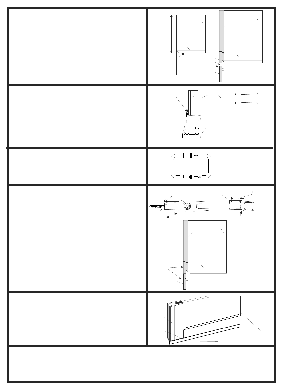
STEP 5 - Clear-Poly Latch Jamb (#7)
* Measure from top of 3/8” Glass Panel #18 to top of the
Buttress.
* Take Clear-Poly Latch Jamb assembly, and remove the Bulb
Seal and Strike Plate, set them aside for later step.
* Cut Clear-Poly Latch #7 to above dimension using a 24 tooth
hatch-saw. Power saw may damage latch.
* Notch the bottom of the Clear-Poly Latch to fit over the end
of the Panel Sill #5 (trim legs up 3/4”).
* Apply the Clear-Poly Latch Jamb on edge of Glass with latch
inside unit ensuring it is flush with the top of the Fixed panel.
* Measure from the bottom of the notched Poly Latch to top of
the Curb Filler. Cut the Buttress Poly latch #10 to this length.
Insert into Vertical channel and butt to bottom of upper poly
latch.
STEP 6 - Attach Door-Side Wall Channel (#3)
* Set door-side Wall Channel #3 in place against the door side
wall, on top of the Curb Filler.
* Gap the bottom of the wall channel 1/16" from the vertical
water dam of the Curb Filler (This will allow the room for the
Door assembly to slide over.)
* Plumb Wall Channel, mark the hole locations on wall and
remove Wall Channel.
* Drill holes with 3/16" bit, insert 3 - #22 Wall Anchors, re-install
* Wall channel and secure with 3 - #21 Screws.
Top of
3/8 Glass
Top of
Buttress
1/16" Gap
Measure
#5
Outside
3/8
Panel
Detail
Front
View
#4
3/4"
Notch
Butt
together
#10
#3
#2
#1
#7
Side
3/8
Panel
#5
Wall
against
#4
STEP 7 - Door Assembly / Pre-Hanging Prep
* Attach Pull - Handle #20 to Door.
* Dry run the position of Magnetic Catch Assembly, #25,
#26 and mark location with marker on glass.
* Apply small bead of silicone inside Catch Assembly
and work onto edge of glass at mark. Let silicone dry.
STEP 8 - Hang Door Assembly
* Slide door assembly over the Wall Channel. (Step 6)
* Adjust door until top edge of the door is level and flush
with top of 3/8” Glass Panel.
* Also ensure door-to-latch gap is consistent from bottom
to top.
* When aligned, secure Door Assembly to Wall Channel
with 3 - #24 screws using factory pilot holes in the
Hinge Jamb.
Finish Latch
* Temporarily slide Strike Plate #9 into Clear-Poly Latch
#7, align with Magnetic Catch #25.
* Mark top and bottom of Strike Plate onto Latch.
* Mark and cut Bulb Seal #8 to proper length.
* From top of latch, re-insert bottom bulb seal, strike and
top seal. Dabs of silicone may be required to secure
Bulb Seals and Strike in place. Hold with Painters tape
while drying.
STEP 8 - Bottom Sweep Fitting (#19)
* Measure the Door Glass including Hinge Rail.
* Subtract 1/16" and cut the Bottom sweep to this length.
* IMPORTANT: The sweep is notch on both ends. You
must leave the notch that goes under the Hinge Rail
for your door. Cut off the end with the notch you don't
need. Trim the inside deflector 3/8" so it will clear the
Latch Jamb when door is closed.
#20
Style Washers
are Optional
S
ecure with
3 - screws #24
Slide door
over wall channel
Butted together
treat as one
continuous
piece latch jamb
#10
Hinge
Rail
Notched
Side
Inside
Handle
Strike Plate #9
Magnetic Catch #25
#7
#4
3/8
Panel
#5
Drip Deflector
on inside
Measure from edge of glass
to outside of hinge rail
Magnet Catch
centered on
handle
Door-to-Latch
Gap (1/16” to 1/8”)
STEP 10 - Final Sealing / Siliconing the Unit (let dry for 24 hours before use)
* On the outside of the unit, run a bead of silicone down both walls and across the bottom where the metal meets
the walls and base. Apply a dab of silicone at the bottom of the latch jamb where it meets the Curb Filler.
Page 8
Page 9
Installation Instructions
Models: SESD180, DESD180 with Notched Panel
1/4" Semi-Frameless Door and 3/8" In-Line Panel
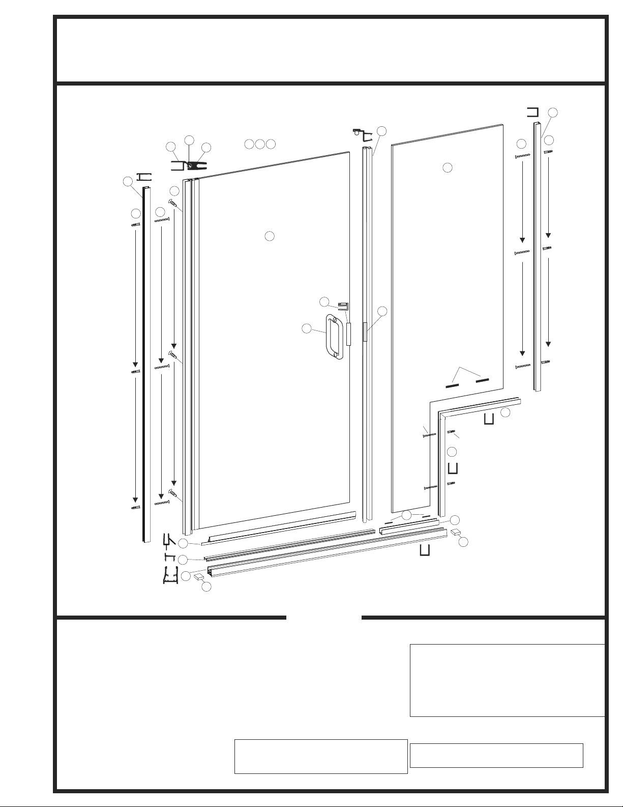
Figure 1 - Exploded View
12
11
3
22
24
21
13
14
16
15
Not Shown
17
25
20
8
21
18
10
#27
4
22
19
2
1
23
1. EX.1022 - Stall Curb - 1
2. EX.1025 - Curb Filler - 1
3. EX.1268 - Hinge Wall Channel - 1
4. EX.1018 - Panel Wall Channel - 1
5. EX.1018 - Panel Sill - 1
6. EX.1018 - Panel Sill Horizontal - 1
7. EX.1018 - Panel Sill Vertical - 1
8. - 10. VN.4075 - Clear PVC Latch Assy - 1
11. - 17. Door Assembly - 1
18. 3/8 Fixed Panel - 1
19. VN.4062 - PVC Drip Deflector - 1
20. HA.2701 - D-Pull Handle - 1
Parts List
21. SP.2101 - #8 X 1-1/2 FHPHSMS - 6
22. SP.2217 - 3/16 X 7/8 Wall Anchor - 6
23. SP.2204 - Foam Plug - 2
24. SP.2110 - #8 X 1/2 PHPH TEK - 3
25. - 26. Magnetic Edge Cap Assy - 1
27. BP.3028 - Setting Block Kit - 1
28. SP.2204 - Centering Clip - 5
29. VN.4033 - VS-20 Dry Glaze Vinyl - 3
Extra screws may be provided
for your convenience
8. VN.4075 - Clear PVC Latch Assy - 1
9. VN.4002 - Bulb Seal - 1
10. SP.2194 - Strike Plate - 1
6
#21
#22
7
25
5
23
11. - 17. Door Assembly EX.1165 - Hinge Jamb - 1
12. VN.4034 - Hinge Sleeve - 1
13. EX.1466 - Hinge Rail - 1
14. SP.2200 - Hinge Pin - 2
15. SP.2181 - Flat Washer - 2
16. SP.2123 - #6 X 1/2 PHPH MS - 2
17. 1/4 Door Glass - 1
Boxed information is assembly detail.
25. Magnetic Cap Assy EX.1619 - Catch - 1
26. SP.2191 - Magnet - 1
Page 9
Page 10
Installation Instructions
Models: SESD180, DESD180 with Notched Panel
1/4" Semi-Frameless Door and 3/8" In-Line Panel
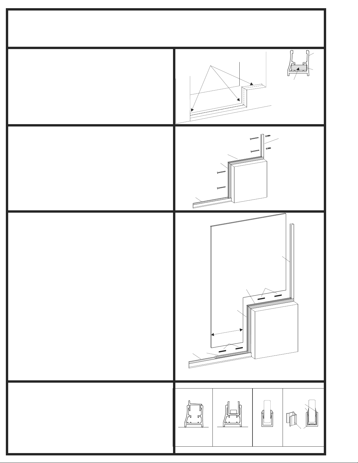
STEP 1 - Curb Installation (#1)
* Measure the wall to face of buttress wall where you want
the center of the unit to be installed.
* Subtract 1/16" from this. Mark location for reference.
* Cut the Stall Curb #1 to this length.
* Insert foam plug into each end of the Stall Curb.
and recess 1/8"
* Fill 1/8” void with silicone.
* Set the curb in place centered over where you marked.
* Secure with blue tape.
* Weep holes are to inside of shower.
* Do not screw the curb to threshold.
STEP 2 - Wall Channel (#4)
* Insert Vert. Wall Channel into curb, on face of buttress.
* Plumb channel with a level.
* Mark the hole locations onto the wall.
* Remove the channel and drill marked locations with
3/16" drill bit.
* Insert 2 - Wall Anchors #22 (may have to razor heads off
anchors flush to wall).
* Re-insert channel and secure with 2 - #21 screws.
* Follow with the Horizontal Channel and tape in place.
* Set Wall Channel #4 on top of the horizontal channel,
plumb with a level. Mark the hole locations onto the wall.
* Drill with a 3/16 bit. Secure with 2 - #21 screws and 3 #22 Wall Anchors.
STEP 3 - Panel Sill (#5) and 3/8” Fixed Panel (#18)
* Measure the lower width of 3/8” Fixed Panel and subtract 3/8”.
* Cut the Panel Sill #5, to this length.
* Set the Panel Sill #5 into the Stall Curb #1 and butt to the Wall
Channel #7.
* Insert two Setting Blocks #27 into both horizontal Panel Sills.
Mark Centerline
location for reference
Measure
Drawing not
proportioned
#7
#21
#1
#6
#21
Pieces are cut
to size based off
your order
#1
#23
Fill void with silicone.
Push towards walls
after curb is set in place.
#4
#22
(outside
of unit)
Wet Glaze Option Only - If using silicone to bond the glass to
the wall channel and sill:
- Install 2 - #28 Centering Clips evenly spaced
into Panel Sill, offset from Setting Blocks.
- Insert 3 - #28 Centering Clips into the Wall channel.
Dry Glaze Option - If using push-in glazing vinyl to set the 3/8”
glass panel, do not use Centering Clips #28.
* Set 3/8” Glass Panel into Panel Sill and Wall Channel.
* Flush glass edge to exposed end of Panel Sill #5.
* Adjust top of glass flush to top of Wall Channel, place additional
setting blocks under glass if needed.
* Ensure vertical edge of 3/8” Glass Panel is plumb.
Wet Glaze Option - Temporarily, but securely fix Glass Panel
into position with blue painter’s tape.
Dry Glaze Option - Holding the glass panel in position, roll or
press the Glazing Bead into both sides of sill and wall channel
using a roller or smooth block of wood.
Check to ensure panel didn’t move.
STEP 4 - Curb Filler (#2)
* Measure from the edge of the 3/8” Glass Panel sill #5
to the Door side wall.
* Cut the Curb Filler #2 to this length.
* With the two forks pointing down and the vertical leg to
the front of the unit, snap the Curb Filler into the Stall
Curb.
* The slope of the Curb filler should be to the inside of the
shower.
Page 10
#4
#6
#27
#7
Measure
#27
#5
#1
*** If using the Dry Seal, once the push in vinyl has been installed, it
cannot be easily removed without being replaced.
Silicone
Bead
Outside
#2 / #1
Cross-section
Outside
#5 / #1
Cross-section
w/ setting block
#29
Dry Glaze
Glazing Bead
#28
Wet Glazing
parts detail
Page 11
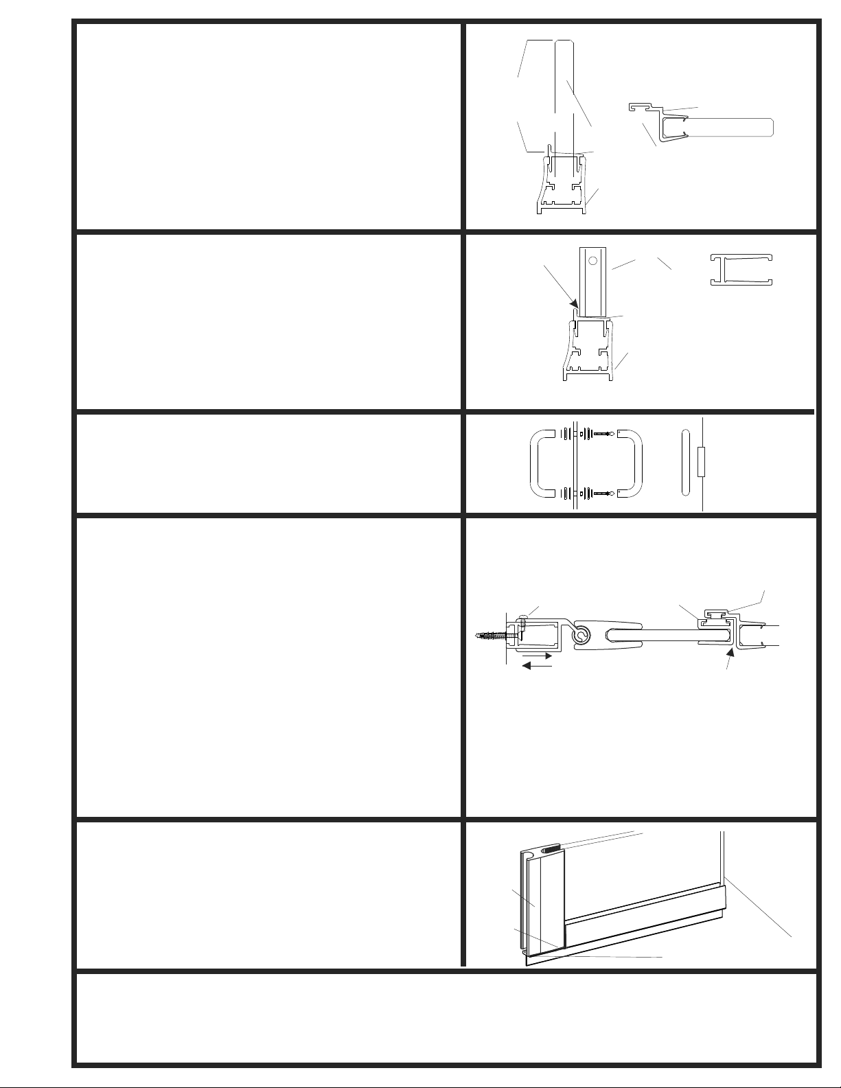
STEP 5 - Clear-Poly Latch Jamb (#8)
* Measure from top of 3/8” Glass Panel #18 to top of the
sloped surface of the Curb Filler #2.
* Take Clear-Poly Latch Jamb assembly, and remove the
Bulb Seal and Strike Plate, set aside for later step.
* Cut Clear-Poly Latch #8 to above dimension using a
24 tooth hatch-saw. Power saw may damage latch.
Recommended: notch the Clear-Poly Latch at bottom to
clear the Panel Sill #5 (trim legs up 3/16”).
* Apply the Clear-Poly Latch Jamb on edge of Glass with
latch inside unit ensuring it is flush with the top of the
Fixed panel.
Measure
(see previous
figure too)
Outside
#18
#2
#1
#8
Top View
#9, #10 (not shown)
outside of unit
STEP 6 - Attach Door-Side Wall Channel (#3)
* Set door-side Wall Channel #3 in place against the door side
wall, on top of the Curb Filler.
* Gap the bottom of the wall channel 1/16" from the vertical
water dam of the Curb Filler (This will allow the room for the
Door assembly to slide over.)
* Plumb Wall Channel, mark the hole locations on wall and
remove Wall Channel.
* Drill holes with 3/16" bit, insert 3 - #22 Wall Anchors, re-install
* Wall channel and secure with 3 - #21 Screws.
STEP 7 - Door Assembly / Pre-Hanging Prep
* Attach Pull - Handle #20 to Door.
* Dry run the position of Magnetic Catch Assembly, #25,
#26 and mark location with marker on glass.
* Apply small bead of silicone inside Catch Assembly
and work onto edge of glass at mark. Let silicone dry.
STEP 8 - Hang Door Assembly
* Slide door assembly over the Wall Channel. (Step 6)
* Adjust door until top edge of the door is level and flush
with top of 3/8” Glass Panel.
* Also ensure door-to-latch gap is consistent from bottom
to top.
* When aligned, secure Door Assembly to Wall Channel
with 3 - #24 screws using factory pilot holes in the
Hinge Jamb.
Finish Latch
* Temporarily slide Strike Plate #10 into Clear-Poly Latch
#8, align with Magnetic Catch #25.
* Mark top and bottom of Strike Plate onto Latch.
* Mark and cut Bulb Seal #8 to proper length.
* From top of latch, re-insert bottom bulb seal, strike and
top seal. Dabs of silicone may be required to secure
Bulb Seals and Strike in place. Hold with Painters tape
while drying.
1/16" Gap
#20
Style Washers
are Optional
S
ecure with
3 - screws #24
Slide door
over wall channel
Outside
#3#3
Side
against
#2
#1
Inside
Handle
Strike Plate #10
Magnetic Catch #25
Wall
Magnet Catch
centered on
handle
Door-to-Latch
Gap (1/16” to 1/8”)
STEP 8 - Bottom Sweep Fitting (#19)
* Measure the Door Glass including Hinge Rail.
* Subtract 1/16" and cut the Bottom sweep to this length.
* IMPORTANT: The sweep is notch on both ends. You
must leave the notch that goes under the Hinge Rail
Hinge
Rail
Drip Deflector
on inside
for your door. Cut off the end with the notch you don't
need. Trim the inside deflector 3/8" so it will clear the
Latch Jamb when door is closed.
Notched
Side
Measure from edge of glass
to outside of hinge rail
STEP 10 - Final Sealing / Siliconing the Unit (let dry for 24 hours before use)
* On the outside of the unit, run a bead of silicone down both walls and across the bottom where the metal meets
the walls and base. Apply a dab of silicone at the bottom of the latch jamb where it meets the Curb Filler.
Page 11
Page 12

Page intentionally left blank
 Loading...