

Page 1
HBZ7115
HobbyZone
®
products are distributed exclusively by
Horizon Hobby, Inc.
4105 Fieldstone Road
Champaign, IL 61822
©2006 Horizon Hobby, Inc.
9035
Instruction Manual
Page 2

Crash damage is not covered
under the warranty.
Be sure to read the warranty
on page 34 and "Warnings and
Safety" on page 30 before you
proceed to Step 1.
Congratulations on your purchase of the HobbyZone® Zone 1
Super Cub. Your Super Cub has come with everything needed
to get you into the air—all in one box, and because it’s a Zone
1 product, it is specifi cally designed for you to be able to teach
yourself how to fl y. You will only need to thoroughly read the
instruction manual, attach the wing, tail, and landing gear, and
then charge the fl ight battery prior to your fi rst fl ight.
HobbyZone’s innovative Anti-Crash Technology is the latest
breakthrough in RC fl ight. Anti-Crash Technology™ (ACT) makes
teaching yourself to fl y easier and safer than ever before. With
ACT, anyone can fl y. Two sensors on the Super Cub, one on the
top and one on the bottom of the fuselage, monitor the position
of the plane in relation to the ground. When the plane is fl ying
level, the top sensor sees the sky, while the bottom sees the
ground, and they tell the onboard computer that the plane is
fl ying correctly. If the plane enters a dive and the sensors detect
that the plane’s orientation is incorrect, the system will automatically correct the control inputs and help prevent the plane from
crashing, allowing you time to regain control. ACT lets you fl y
without worry. And once you’ve gained experience with your
Super Cub, you can turn ACT off for more complete control and
increased maneuverability.
Your HobbyZone Super Cub comes with everything needed to
get you into the air. A video compact disc (VCD) is also included
to give you some helpful hints before you take to the sky for the
fi rst time, and includes fl ying footage.
Page 3
4
Step 2
5
Step 1
1. Turn on the transmitter.
2. Install the fl ight battery into the
battery compartment (located at the
bottom of the fuselage) and plug it
into the connector. (The transmitter
should ALWAYS be turned on prior to
installing fl ight battery, and should
be turned off AFTER the fl ight battery
has been unplugged).
3. Make sure clothing, fi ngers, and
property are clear of the propeller,
and ensure you have a good grip
on the plane. Move the slide throttle
all the way back to arm the motor,
and then slide the throttle forward
slowly. The propeller should spin at a
high speed when the throttle is
moved forward. (If the prop does
not spin, the battery is suffi ciently
discharged and you can go straight
to the instruction section for charging
the battery—Step 3).
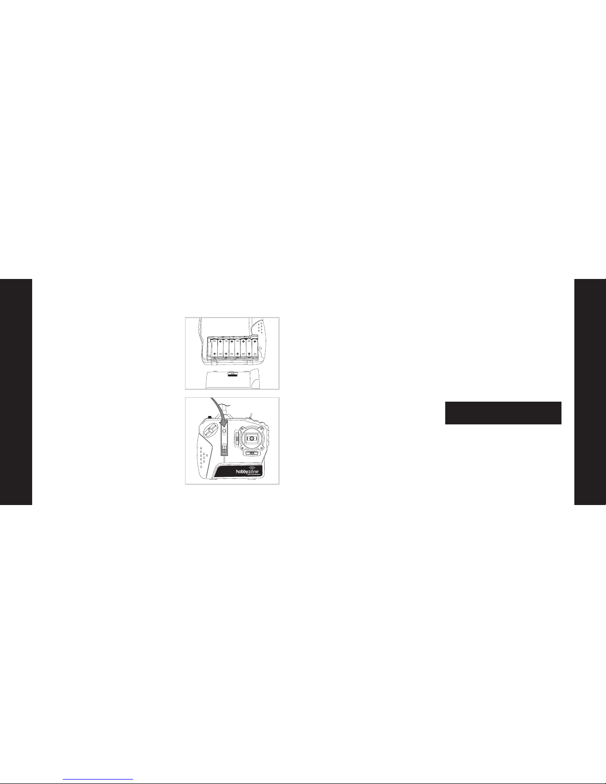
1. Remove the battery cover and install
the included 8 AA batteries.
2. Be certain that you observe proper
polarity when installing the batteries,
and then replace the cover on the
transmitter.
3. To test the transmitter’s function,
turn on the switch on the front of the
transmitter. The LED should glow
brightly.
4. Replace the batteries with fresh AA
batteries when you hear the low
voltage battery alarm beeping.
5. Once the alarm goes off, you only
have a few minutes of power left,
so don’t delay landing your plane
any longer than necessary to land
it safely.
Installation of Batteries into the Transmitter Motor Test and Battery Discharging
WARNING: Keep everything clear of the propeller
at all times! A moving propeller can cause severe
injury and damage.
4. Keep the throttle advanced until the
propeller slows and fi nally stops. This
means the battery is fully discharged
and ready to be fully charged with
one of the included chargers.
5. After you have ensured the motor
functions correctly and the battery
is completely discharged, unplug
the fl ight battery and then turn off
the transmitter.
Page 4
Step 3
7
Step 3
6
DC Peak Charger Maximum
Charge Rates
4.8V 600mAh Ni-MH .8 amps
(requires HBZ1027)
6.0V 600mAh Ni-MH .8 amps
(requires HBZ1027)
4.8V 300mAh Ni-MH .4 amps
(requires HBZ1027)
7.2V 900mAh Ni-MH 1.2 amps
7.2V 1000mAh Ni-MH 1.2 amps
8.4V 1000mAh Ni-MH 1.2 amps
WARNING: If you exceed the maximum charge rate
recommended above, you can cause permanent
damage to the charger and battery, and in some
cases, may cause a fi re.
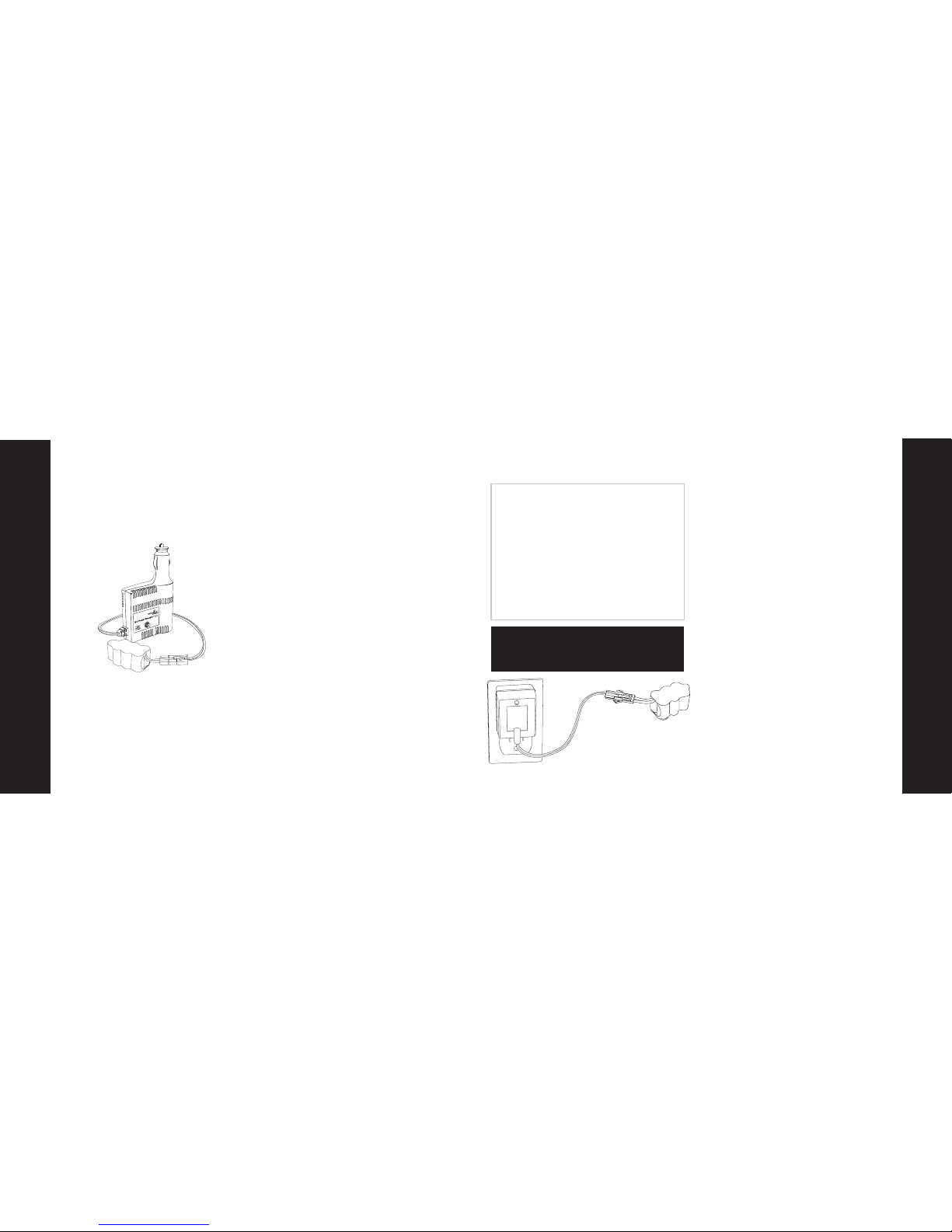
Charging the Aircraft Battery
Your Super Cub comes with a variable
rate DC peak charger, as well as an AC
peak charger. This way, you can use the
charger that best fi ts your needs.
DC peak charger features:
• Adjustable charge rate from
300mAh—1.2A
• LED indicator
• Peak charges 4- to 7-cell Ni-Cd and
Ni-MH battery packs
1. Select the charge rate of 1.2A for
charging the included 8.4V 1000mAh
battery pack.
2. Connect the battery to the charger.
3. Plug the charger into a12V power
outlet of an automobile. Adult super vision is required. PLACE BATTERY
ON HEAT-RESISTANT SURFACE
DURING CHARGING.
4. The LED of the charger will blink on
and off steadily while fast charging.
5. When the LED glows solid, the charger
automatically switches to a trickle
charge, indicating that the battery
is charged. The battery will feel warm
when it is charged.
6. We recommend that you peak charge
your battery within a few hours of
fl ying your Super Cub.
1
.0
1.2
H
B
Z
1
0
2
6
.3
.4
.6
.8
AC peak charger features:
• Delta peak charging circuitry safely
charges your battery pack
• 500mAh charge rate for 8.4V batteries
• 400mAh charge rate for 9.6V batteries
• LED and timer
• Charges only 7- and 8-cell Ni-MH
battery packs
1. Plug the battery pack into the
connector of the AC peak charger.
2. Plug the AC peak charger into a
standard 110/120 AC wall outlet and
place the battery on a heat-resistant
surface while charging.
3. Never leave the charger and battery
unattended during charging.
4. In about 2 hours, a completely
discharged battery pack will be fully
charged. The LED will fl ash while
charging and glow solid when the
pack is fully charged, and the battery
will feel warm.
5. We recommend that you peak charge
the battery shortly before fl ying.
Page 5
Step 5
Attaching the Wing
Step 4
8
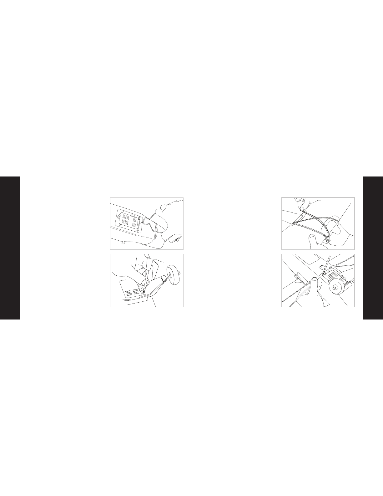
Landing Gear Attachment
1. Locate the included wire landing gear.
2. Slide landing gear into the allotted
slot on the bottom of the fuselage.
3. Make sure the gear is securely in the
slot by gently pulling on it after it is
attached.
4. Attach the white plastic scale covers
with the included 4 screws, as shown.
They are located in the small bag
labeled “A.”
1. Locate the wing and wing strut
screws that are included.
2. Place the wing so that it is centered
on the top of the fuselage.
3. Use the included rubber bands to
secure the wing by attaching two
bands straight across the top of the
wing, where each end is attached to
each set of band holders, and criss crossing two diagonally across the
top of the wing.
4. After you are satisfi ed that the wing
is properly centered on the fuselage,
turn the plane over and complete the
wing attachment by attaching the
struts, as shown. The screws that will
be used to attach the struts are in the
small bag labeled “B.”
5. Make certain the wing is properly
attached and centered prior to each
fl ight.
9
Page 6
Step 6
11
Step 6
10
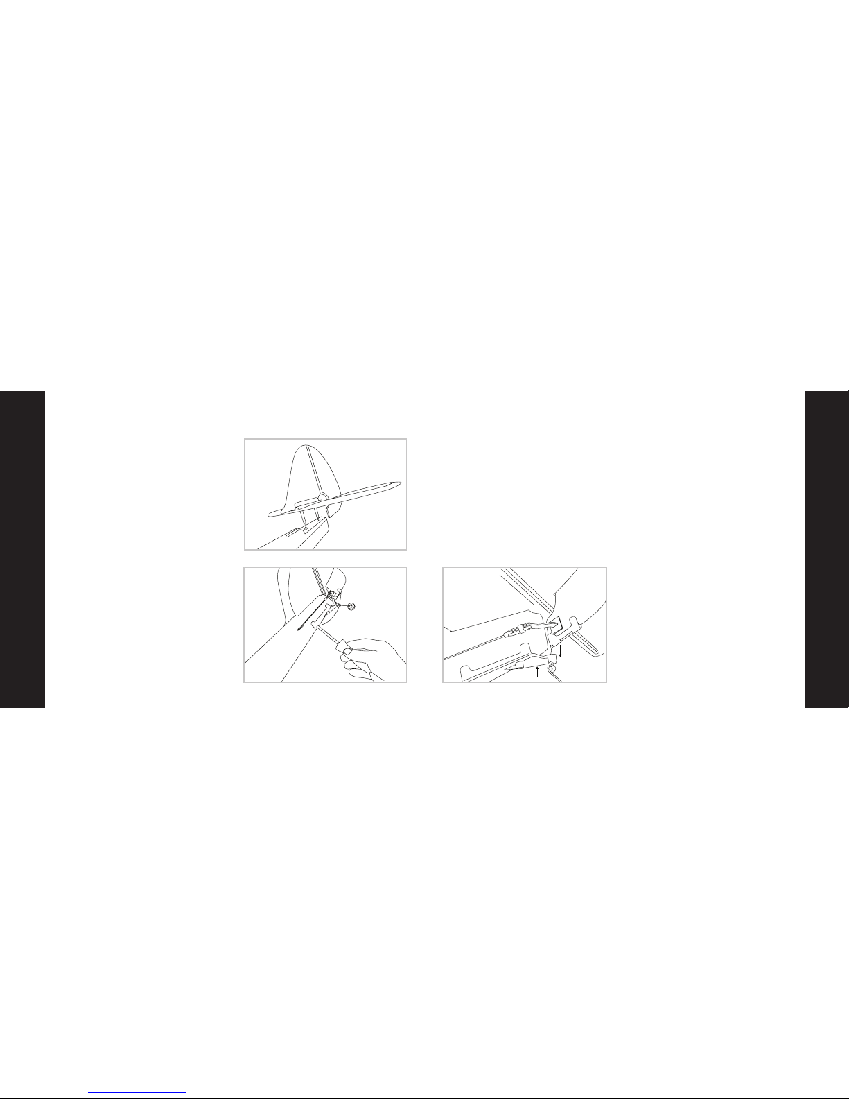
Attaching the Tail
1. Locate the rudder and horizontal
stab assemblies and carefully remove
them from the box. It may be helpful
to watch the included video when
installing the tail section.
2. Install the rudder assembly into the
horizontal stab, as shown.
3. Install the complete tail assembly
into the fuselage, as shown.
4. Secure this assembly to the fuselage,
from the bottom, with the included
screws. The 2 screws needed for this
step are in the small bag marked
“C” and are the two longest included.
5. Clip the tail wheel wire into the
plastic wheel housing by pulling
down slightly on the tail wheel, while
at the same time you are pushing up
on the plastic molding until the two
parts “snap” together.
6. Attach the clevis from the rudder
pushrod into the outermost hole
of the control horn on the rudder, and
slide the clear rubber sleeve down
over the clevis.
7. Attach the clevis from the elevator
pushrod into the outermost hole
of control horn on the bottom of the
elevator. Slide the clear rubber sleeve
down over the clevis. Again, refer
to the instructional video for a more
detailed explanation.
push up
pull down
Page 7

Step 2
Step 2
12 13
1. Make certain the throttle slider is
in the “off” position. Turn on the
transmitter.
2. Install the fl ight battery in the
fuselage and plug the battery lead
into the lead inside the airplane.
3. Move the stick on the transmitter
(rudder control) side to side while
observing the vertical control surface
is moving per the input (as shown).
Tail Control Test
WARNING: ALWAYS KEEP CLEAR OF THE PROPELLER IN THE EVENT THAT YOU ACCIDENTALLY
TURN ON THE MOTOR!
4. Push the stick full forward (elevator
control). When this is done, the
horizontal control surface should
move down (as shown), causing the
plane to pitch down.
5. Pull back on the stick (elevator
control). When this is done, the
horizontal control surface should
move up (as shown), causing the
plane to pitch up.
Step 7
Step 7
Right
Left
6. If your airplane is not responding,
DO NOT FLY IT! Call the Horizon
Hobby Product Support line at
1-877-504-0233.
7. When you are satisfi ed your airplane
is set up properly, you can unplug
the fl ight battery and then turn off
the transmitter. This should be done
every time you have fi nished fl ying.
NOTE: It is very important to make
sure that the control surfaces (rudder
and elevator) are at 0 degrees. Ideally,
they will be at 0 degrees when the
levers are centered. The next step explains how to make adjustments to the
control surface.
Down
Up
Page 8

Step 2
Step 8
14
Making Adjustment to the Control Surfaces
1. Any changes necessary to bring both
the rudder and elevator to neutral
(zero degrees) should be able to be
done by using the trim levers on the
transmitter. To do this, place the
control stick at center, and use the
slider button below the stick to
adjust the rudder (vertical surface)
until it is fl ush with the stationary
section of the rudder assembly. To
adjust the movable section of the
elevator so that it is fl ush with the
stationary section of the elevator
assembly, use the slider button to
the left of the control stick.
2. After this, if you fi nd you are not able
to get the control surfaces fl ush with
each other, do not fl y until things
have been corrected.
3. If corrections are needed, and moving
the trim lever(s) is not adequate,
you will need to:
a. Turn on the transmitter.
b. Insert the battery pack into the
fuselage and plug the battery into
the lead from the airplane.
c. Return the trim levers to center.
d. Remove the clevis from the control
surface horn and adjust the length of
the pushrod by turning clevis the
appropriate direction. Turning clock wise makes the pushrod shorter and
counterclockwise makes it longer.
Elevator
Tri m
Rudder Trim
15
Choose a Large, Open Grass Field
Step 9
In order to have the most success,
and to protect property and your
Super Cub, it is very important to
select a place to fl y that is very open.
The site should:
• Have a minimum of 300 feet
(90 meters) of clear space in
ALL directions.
• Be clear of pedestrians.
• Be free of trees, buildings, cars,
power lines, or anything that could
entangle your airplane or interfere
with your sightline.
• Remember, your Super Cub can reach
speeds of up to 30 mph (48 k/h), so it
can cover ground quickly.
• Plan on fl ying in an area that gives
you more space than you think you
need, especially with fi rst fl ights.
600 feet
Page 9

Step 2
Step 2
16
Step 10
Choose a Calm Day
We know you want to fl y your Super
Cub as soon as you have it. However,
fl ying in too much wind can place your
aircraft in jeopardy. On your fi rst fl ights,
make sure that the winds are no more
than 5–7 mph (8–11 k/h).
To check the wind conditions:
• Tie the antenna ribbon to the
transmitter.
• Hold the transmitter so the antenna
is parallel to the ground.
If the fl ag hangs down, it is calm
enough to fl y. If the angle between the
antenna and the fl ag is less than 20
degrees, it is too windy and you need
to postpone your fl ight.
17
Step 11
Range Test
Prior to your fi rst fl ight, you will need
to perform a range test. Two people
are needed to do this—one to hold the
airplane and one to hold the transmitter.
1. One person holds the transmitter
while the other person walks 100
paces away with the Super Cub.
2. Be sure the throttle slider is in the
“off” position.
3. Extend the antenna and turn on the
transmitter.
4. Plug in the fl ight battery, close the
hatch cover, and turn the latch so the
hatch cover stays in place.
5. As soon as the throttle is advanced,
the prop should spin quickly.
6. As the person moves the transmitter
controls, the airplane should respond
correctly with the controls operating
smoothly.
Warning: The person holding the airplane needs to
make sure the propeller will not come in contact with
any clothing, hair, or parts of the body.
100 paces
too windy
calm
maximum
allowed wind
Page 10

Step 2
Step 2
The electronic system connected to the
sensors knows that the airplane (with
ACT “on”) should not be allowed to
enter a steep dive. If you give transmitter
input that causes the plane to enter
into a steep dive that could lead to a
crash, the ACT software will override
your input to help prevent the aircraft
from crashing to the ground. ACT will
cut the power going to the motor and
add some up elevator, as well. This
causes the nose of the airplane to pull
up, thereby helping to prevent your
aircraft from crashing. However, in
order for ACT to work properly, there
has to be suffi cient altitude for recovery
(at least 200 feet or 61 meters). ACT
will only interrupt fl ight in extreme situations, allowing you to enjoy as much
control of your Super Cub as you need.
18
Step 12
Anti-Crash Technology (ACT)
Your HobbyZone® Super Cub comes
equipped with exclusive Anti-Crash
Technology.
™
This software will help to
prevent crashes due to over-control.
The sensors that are located on the
fuselage “see” the horizon. One sensor
is located at the top of the windshield
and the other is on the bottom side
of the fuselage, in front of the landing
gear.
Remember, the purpose of Anti-Crash
Technology is to help you learn to fl y
properly and smoothly. When ACT is
engaged, it means you have placed
your aircraft in jeopardy. Keeping the
stick more in the middle, and less to
the “corners” of the transmitter, will
allow you to fl y more smoothly and
prevent ACT from engaging. The key is
to learn to make minor movements on
the controls. The transmitter is proportional and is sensitive to movements of
the control stick. Once you have gained
more experience, and feel comfortable
fl ying, you can turn off ACT and have
full control at all times. It is possible to
change fl ight modes (turn ACT on or
off) while in fl ight, but suffi cient altitude
is required.
To turn off ACT, simply move the switch
on the top of the transmitter to the
appropriate position.
19
Step 12
If, with ACT™ on, you enter into a threatening dive, you will notice the following:
• You will hear the motor power de crease as the ACT programming
overrides your input. This slows the
speed of the airplane and will reduce
the risk of a crash.
• The ACT software will give up elevator
input to help pull the nose up and
out of the dive.
• Once the ACT software has been
engaged (takes over), you will not
regain control until after you have
released the steering stick and
returned it to neutral.
With ACT
Without ACT
Page 11

ACT Flying Tips
Step 12
20
• Never fl y at too low of an altitude
and expect ACT
™
to save you from
a crash. You must maintain an altitude
of at least 200 feet (61 meters) for
the software to be able to help
prevent crashes.
• Even when fl ying with ACT on, if you
feel that your aircraft is in jeopardy
reduce the throttle immediately and
release the stick. You can then add a
small amount of up elevator (pull
back slightly on the stick), as well, to
aid the recovery.
• Because the sensors are used to
activate the protective software,
there may be times when they can
be fooled. This may be especially
true when fl ying in very bright sun
shine and/or when the sun is close
to the horizon.
• With ACT on, never fl y over water,
light colored sand, ice, snow, or
Step 13
21
anything else that can refl ect light
and “fool” the sensors.
• Never fl y in too tight of an area.
Anti-Crash Technology
™
will not
prevent you from crashing into
trees, buildings, or other obstacles.
• Make several successful fl ights
(including several soft landings) prior
to attempting to fl y with ACT off.
• Never let the aircraft fl y too far down
wind from you, which can cause the
aircraft to fl y away.
• It is always a good idea to have an
experienced pilot who has mastered
control with at least a 3-channel
radio system to help you on your
fi rst fl ights.
Your HobbyZone
®
Super Cub is
equipped with a third channel for pitch
control (elevator). Pulling back on the
transmitter stick will cause the nose of
the airplane to raise and allows for more
tighter turns, shorter runway take-offs,
fl ares for landing, a better climb rate,
and the ability to perform aerobatic
maneuvers, such as loops and stalls.
However, giving too much UP elevator
(pulling back too much on the stick) can
also place your aircraft in jeopardy, as
your airplane can enter an unplanned
stall, especially when the plane is traveling at slower speeds.
Using Elevator (Pitch Control)
Just after a stall occurs, the nose of the
airplane will go down, and the airplane
will begin to enter a dive. To recover
from a stall, pull the stick back slowly
(UP elevator) to pull the nose up and
out of the dive. This should return the
airplane to straight and level fl ight. Be
careful, as pulling back too quickly or
too far will once again cause the plane
to enter a stall.
Page 12

Hand Launch
Step 14
22
On fi rst fl ights, it is a good idea to have
a second person, ideally an adult, help
you launch the plane. This will allow
you to focus entirely on the transmitter
input.
1. Make sure the battery is fully charged
and has recently been peaked.
2. Make certain that no one is fl ying, or
preparing to fl y, on the same channel
within approximately ½ mile (.8
kilometers). If someone were to turn
on a transmitter on the same frequency
as yours, you will lose control of your
airplane. This could cause damage
to your airplane, cause it to fl y away,
or cause damage to other property
if your airplane were to crash into
it. When you are confi dent it is safe
to turn on your transmitter, you can
move on to the next step.
3. Install and plug in the fl ight battery.
4. If you are hand launching the aircraft
yourself, place the plane in your right
hand and the transmitter in your
left hand.
5. Use caution and advance the throttle
to FULL.
6. Take a few steps forward, and launch
the airplane DIRECTLY and fi rmly into
the wind, while keeping the airplane
and its wings level with the ground.
7. Allow the plane to climb steadily
at full throttle, into the wind, until you
have achieved an altitude of 100 to
150 ft (30 to 46 meters). You will not
need to use elevator in order for your
airplane to climb. A few clicks down
on the elevator trim should allow a
steady climb.
Step 15
23
Runway Takeoff (ROG)
Your HobbyZone® Super Cub can be
launched by way of a runway takeoff
(ROG). However, this is not recommended
for inexperienced pilots.
1. Make sure your landing gear is
properly installed.
2. Stand behind your Super Cub and
point it directly into the wind on
smooth asphalt or concrete.
3. Apply FULL power via the throttle
slider and adjust the control stick as
necessary to keep the aircraft headed
directly into the wind.
4. If the battery is fully charged, your
Super Cub should lift off the ground
in approximately 30 feet (12 meters).
Apply some UP elevator by pulling
back on the stick, and the plane will
lift off of the ground in a shorter
distance. Remember, only a small
amount of UP is needed. Too much
will cause a stall after your aircraft
has left the ground.
Page 13

Step 16
24
1. After you have launched your Super
Cub, it will begin climbing at full
throttle. With the throttle advanced
all the way forward, your Super Cub
should not need any elevator input to
climb steadily.
2. Make adjustments on the throttle
slider and control stick that are
necessary to keep your aircraft
heading directly into the wind.
Do not attempt a turn until you have
reached a minimum of 50–100 feet
(15.25–30.5 meters) of altitude
(about as tall as a four-story building).
3. Control range is 2500 feet (762
meters), so if you fl y beyond that, you
will lose control of your airplane. At
that distance, however, you would
likely lose sight of your airplane
before you’d lose control.
Flying
4. Don’t let your airplane get too far
downwind from you. Always fl y with
the airplane UPWIND from you.
Failure to do this could result in a fl y away! Remember, the wind is stronger
as your plane fl ies higher in the air.
It’s ok to fl y higher, just be cautious
and watch how your plane reacts to
the wind. Most of the time, you can
fl y at higher altitudes at half-throttle.
This is great for smooth, easy fl ying
when you’re fi rst learning to fl y, and
conserves battery power.
5. When you have reached higher
altitudes and want to practice using
the elevator, begin with small and
smooth inputs to the transmitter. Very
little input is needed to get the plane
to turn, climb, or descend.
6. Avoid long vertical dives, with the
motor on or off, as it can cause a lot
of stress on the aircraft.
Step 16
25
7. It may be helpful to fl y in smooth
large ovals at higher altitudes so that
you can get used to steering the
plane with the nose coming at you.
Flying the with plane coming towards
you takes some practice and is one of
the hardest things to get used to
when you fi rst begin to fl y.
Sharp Turns: Move the stick in the direction you want to turn and add a bit of
UP elevator at the same time (pull back
on the stick). The plane will make a
sharper banking turn.
Rudder Trim: If the HobbyZone
®
Super
Cub seems to drift in one direction
when the control stick is in the neutral
(centered) position, gradually move the
rudder trim lever (below the control
stick) in the OPPOSITE direction of the
drift. Adjust until the plane fl ies straight
with the control stick at neutral.
Elevator Trim: If the model “hunts” up
or down, use the trim lever to the left
of the stick to correct this problem. If
it hunts up, slide the left trim lever up
one notch at a time until it fl ies level. If
it hunts down, slide the left trim lever
down one notch at a time until it fl ies
level. The model should fl y straight
with the stick at neutral. Your Super
Cub should have a steady climb at full
throttle when it is trimmed properly.
Page 14

Full Throttle
Full Throttle
50% Throttle
Reduced Throttle
Step 17
26
Throttle Adjustment
1. When launching, the throttle should
be all the way on.
2. Once you have achieved the altitude
where you want to fl y, you can reduce
throttle to about 50% for cruising.
This will also allow for longer fl ights.
3. If you want to reduce altitude, reduce
throttle to less than 50%.
4. To increase altitude again, increase
throttle to more than 50%.
Landing
27
When you notice that your HobbyZone®
Super Cub no longer climbs well under
full power, normally after about 10–12
minutes, the battery is getting low and
it is time to land. Line the airplane up
directly into the wind toward the desired landing spot. At about 10–15 feet
(3–4.5 meters) of altitude, reduce the
throttle gradually until it is completely
shut off. Your airplane will glide in for a
landing.
Auto Cutoff: When the battery gets low
enough, this feature will automatically
shut off the motor and save enough
battery power to maintain control of the
tail so you can land correctly and safely.
If the motor cuts off, prepare to land
immediately. If you are gliding down
and have some time to rest the battery,
you may re-arm the motor by moving
the throttle slider back to off and then
advancing it again. This will only allow
Step 18
the motor to run briefl y, and may allow
you to better adjust your landing. Do
not re-arm the motor more than once.
Warning: Do not attempt the catch the
airplane or injury may occur. Turn the
motor off prior to touchdown in order
to prevent damage to the wing and/or
propeller.
Expert Tip: As you get more experienced at fl ying, try adding a small
amount of UP elevator just before
touchdown to “fl are” the airplane. With
more and more practice, your landings
will be smooth and on target.
Note: If you’re fl ying with the motor
off, or at a slow speed, allow the
HobbyZone
®
Super Cub a bit more
area for turns.
10 FT
Reduce power at 10 feet
Page 15

28
Aerobatic Flight
It is recommended in the directions that
the Super Cub controls be set for softer
responses and at the outer holes of the
control surfaces. However, once you get
used to the fl ight characteristics and
want to perform more aerobatic maneuvers (with ACT
™
off) you can change the
amount of throw that is permitted by
moving the clevises to the inner holes
of the control horns. After making any
adjustments, always turn on the transmitter, center the transmitter trim levers,
and make sure the control surfaces are
even. Make the proper adjustments to
make the surfaces even, if they are not
(see Step 8).
Note: By making these changes, the
controls will be much more responsive.
However, this makes the airplane much
less forgiving and it will be easier to
stall. Remember, crash damage is not
covered under the warranty.
Step 19
29
Repairing Minor Damage
If you happen to crash, and part of the
tail or wing breaks, it can be repaired
by using packing tape to cover the
missing pieces. Also, any type of CA
will help repair the foam fuselage and
wing. However, if damage is severe, or
if the wing and/or tail are bent, replace
the damaged parts prior to fl ying again.
There is a complete list of replacement
parts in the back of this manual.
Replace wing immediately
Page 16

30
Warnings and Safety Checklist
1. Read and follow this manual and
included video CD completely,
observing all instructions and safety
directions. If you do not do this,
serious injury and damage can occur.
Think about safety fi rst.
2. Keep the propeller away from all
body parts at all times! Beware of
loose clothing or hair becoming
entangled in the propeller.
3. Never fl y when it is too windy or you
may lose control of the airplane.
Never fl y near people, vehicles, train
tracks, buildings, power lines, water,
or trees, and never attempt to catch
the airplane.
4. Adult supervision is recommended
for ages 12 and under.
5. Only use a battery charger that is
compatible for use with the Super
Cub battery. We recommend using
the chargers that come with your
airplane. Never leave the chargers
unattended while charging! During
charging, place the battery and
charger on a heat-resistant surface.
Do not place them on carpet or
upholstery.
6. Never cut into the battery charger
or airplane wires, or serious injury can
occur. Causing the battery to short
out (crossing negative and positive
bare wires) can cause a fi re, serious
injury and damage.
31
7. Hold the plane securely, and keep
all body parts away from the pro peller at all times. Carry the plane
as though the propeller could start
spinning at any time when you have
the battery pack plugged into the
lead from the plane.
8. After you have fi nished fl ying, or at
any time you have the radio system
on, ALWAYS unplug the battery
prior to turning the transmitter off.
ALWAYS turn on the transmitter prior
to plugging the fl ight battery in.
9. Never fl y on the same frequency as
another RC vehicle in your area.
Doing so will cause you, or the other
person, to lose control of your plane.
Page 17

32
Troubleshooting
Unit does not operate 1. Transmitter "AA"batteries are depleted
or installed incorrectly as indicated by a
dim or unlit LED on the transmitter or the
low battery alarm
2. No electrical connection
3. Flight battery is not charged
4. Crash has damaged the radio inside
the fuselage
1. Check polarity installation or replace with
fresh “AA” batteries
2. Push connectors together until they click
3. Fully charge the battery
4. Replace the fuselage or receiver
Aircraft keeps turning in
one direction
1. Rudder or rudder trim is not adjusted
correctly
2. Wing is not centered over the fuselage
1. Adjust stick trim lever or adjust rudder
position (see page 14)
2. Center the wing
Aircraft is difficult
to control
1. Wing or tail is damaged 1. Replace damaged part
Aircraft keeps pitching
up steeply
1. Wind is too gusty or strong
2. Elevator is trimmed 'up' too much
1. Postpone flying until the wind calms down
2. Adjust elevator trim 'down'
Aircraft won't climb 1. Battery is not fully charged
2. Elevator may be trimmed 'down'
1. Charge battery fully shortly before flying
2. Adjust elevator trim 'up' (see page 14)
PROBLEM
POSSIBLE CAUSE
SOLUTION
33
1. Don’t fl y in winds over 7 mph (11 K/h).
First-time pilots should get help from
an experienced radio control pilot
during fi rst fl ights.
2. Choose your fl ying fi eld carefully–
grass and soft ground with a 600-foot
(183-meter) diameter of open space
is optimal for fl ying and will lengthen
the life of the Super Cub. Make sure
there are no obstacles that will get
in your way when fl ying, such as trees
or buildings. Make sure you do not fl y
where there are pedestrians who
could be hurt by the airplane.
3. Remember that holding the stick full
over for too long can cause the
airplane to spiral dive and crash.
At the very fi rst sign of the Super Cub
beginning to spiral down, immediately
release the stick and give the
opposite turn control to the spiral,
then pull back on the elevator gently
to level fl ight and level the wings.
4. Don’t attempt to fl y or do maneuvers
beyond your fl ying abilities without
seeking the assistance of an experi enced pilot.
5. If you’re gliding with the motor off,
allow the Super Cub more area for
turns.
6. Position yourself at your fl ying fi eld
to keep the sun at your back and out
of your eyes. Wear sunglasses on
bright days.
7. Keep the Super Cub upwind, espe cially on windier days, to prevent it
from “fl ying away.” The wind is
normally stronger at higher altitudes
than it is on the ground.
8. Keep your plane in front of you so
you don’t have to turn in circles as
you fl y. Try to avoid fl ying directly
overhead.
Success Tips
Page 18

Limited Warranty Period
Horizon Hobby, Inc. guarantees this
product to be free from defects in both
material and workmanship at the date
of purchase.
Limited Warranty & Limits of Liability
Pursuant to this Limited Warranty,
Horizon Hobby, Inc. will, at its option,
(i) repair or (ii) replace, any product
determined by Horizon Hobby, Inc. to
be defective. In the event of a defect,
these are your exclusive remedies.
This warranty does not cover cosmetic
damage or damage due to acts of God,
accident, misuse, abuse, negligence,
commercial use, or modifi cation of or
to any part of the product. This warranty does not cover damage due to
improper installation, operation, maintenance, or attempted repair by anyone
34
Warranty and Follow-Up Procedures
other than an authorized Horizon
Hobby, Inc. service center. This warranty
is limited to the original purchaser and
is not transferable. In no case shall Horizon Hobby’s liability exceed the original
cost of the purchased product and will
not cover consequential, incidental or
collateral damage. Horizon Hobby, Inc.
reserves the right to inspect any and all
equipment involved in a warranty claim.
Repair or replacement decisions are at
the sole discretion of Horizon Hobby,
Inc. Further, Horizon Hobby reserves the
right to change or modify this warranty
without notice.
REPAIR OR REPLACEMENT AS PROVIDED UNDER THIS WARRANTY IS THE
EXCLUSIVE REMEDY OF THE CONSUMER. HORIZON HOBBY, INC. SHALL
NOT BE LIABLE FOR ANY INCIDENTAL
OR CONSEQUENTIAL DAMAGES.
35
As Horizon Hobby, Inc. has no control
over use, setup, fi nal assembly, modifi cation or misuse, no liability shall be
assumed nor accepted for any resulting damage or injury. By the act of use,
setup or assembly, the user accepts all
resulting liability.
If you as the purchaser or user are not
prepared to accept the liability associated with the use of this product, you
are advised to return this product immediately in new and unused condition
to the place of purchase.
Safety Precautions
This is a sophisticated hobby product
and not a toy. It must be operated
with caution and common sense, and
requires some basic mechanical ability.
Failure to operate this product in a safe
and responsible manner could result
in injury or damage to the product
or other property. This product is not
intended for use by children without
direct adult supervision.
The product manual contains instructions for safety, operation and maintenance. It is essential to read and follow
all the instructions and warnings in the
manual, prior to assembly, setup or use,
in order to operate correctly and avoid
damage or injury.
Questions, Assistance, and Repairs
Your local hobby store and/or place
of purchase cannot provide warranty
support or repair. Once assembly, setup
or use of the product has been started,
you must contact Horizon Hobby, Inc.
directly. This will enable Horizon to better answer your questions and service
you in the event that you may need any
assistance.
Page 19

Step 2
Step 2
36
Questions or Assistance
For questions or assistance, please
direct your email to productsupport@
horizonhobby.com, or call 877.504.0233
toll free to speak to a service technician.
Inspection or Repairs
If your product needs to be inspected
or repaired, please call for a Return
Merchandise Authorization (RMA). Pack
the product securely using a shipping
carton. Please note that original boxes
may be included, but are not designed
to withstand the rigors of shipping
without additional protection. Ship via
a carrier that provides tracking and
insurance for lost or damaged parcels,
as Horizon Hobby, Inc. is not responsible for merchandise until it arrives and
is accepted at our facility. Include your
complete name, address, and phone
number where you can be reached
Warranty and Follow-Up Procedures (continued)
during business days, RMA number, and
a brief summary of the problem. Be sure
your name, address, and RMA number
are clearly written on the shipping
carton.
Warranty Inspection and Repairs
To receive warranty service, you must
include your original sales receipt
verifying the proof-of-purchase date.
Providing warranty conditions have
been met, your product will be repaired
or replaced free of charge. Repair or
replacement decisions are at the sole
discretion of Horizon Hobby.
Non-Warranty Repairs
Should your repair not be covered by
the warranty and the expense exceeds
50% of the retail purchase cost, you will
be provided with an estimate advising
you of your options. You will be billed
for any return freight for non-warranty
37
repairs. Please advise us of your preferred method of payment. Horizon
Hobby accepts money orders and
cashiers checks, as well as Visa, MasterCard, American Express, and Discover
cards. If you choose to pay by credit
card, please include your credit card
number and expiration date. Any repair
left unpaid or unclaimed after 90 days
will be considered abandoned and will
be disposed of accordingly.
Electronics and engines requiring inspection or repair should be shipped to
the following address (freight prepaid):
Horizon Service Center
4105 Fieldstone Road
Champaign, Illinois 61822
All other products requiring inspection
or repair should be shipped to the following address (freight prepaid):
Horizon Product Support
4105 Fieldstone Road
Champaign, Illinois 61822
Page 20

Step 2
Step 2
PART# DESCRIPTION RETAIL PART# DESCRIPTION RETAIL
Replacement Parts
PKZ1005 Propeller $3.49
HBZ7104 Prop Shaft with Tires $2.49
HBZ7106 Landing Gear with Tires $5.99
HBZ7107 Spinner $0.99
HBZ7110 Decal Sheet $3.99
HBZ7112 Battery Door with Latch $1.99
HBZ7114 Firewall with Screws $1.79
HBZ7115 Instruction Manual $0.99
HBZ7116 Instruction VCD $2.99
HBZ7117 Tail Wheel $2.99
HBZ7120 Standard Wing with Struts $19.99
HBZ7121 Control Horns (4) $1.29
HBZ7122 Wing Struts with Screws $2.19
HBZ7124 2 Wing Hold Down Rods $1.49
HBZ7125 Tail with Accessories $11.99
HBZ7126 Cowl $2.99
HBZ7127 White Rubber Bands $0.99
HBZ7128 Pushrods and Clevis Set $0.99
HBZ7129 Gearbox with Firewall $8.99
HBZ7130 AC Peak Charger w/Timer $19.99
HBZ7134 Motor with Pinion $10.99
HBZ7135 Metal Pinion (2) $0.99
HBZ7151 ESC/Receiver Ch.1 $29.99
HBZ7152 ESC/ Receiver Ch. 2 $29.99
HBZ7153 ESC/ Receiver Ch. 3 $29.99
HBZ7154 ESC/ Receiver Ch. 4 $29.99
HBZ7155 ESC/ Receiver Ch. 5 $29.99
HBZ7156 ESC/ Receiver Ch. 6 $29.99
HBZ7161 Fuselage, Ch. 1, 26.995 $69.99
HBZ7162 Fuselage, Ch. 2, 27.045 $69.99
HBZ7163 Fuselage, Ch. 3, 27.095 $69.99
HBZ7164 Fuselage, Ch. 4, 27.145 $69.99
HBZ7165 Fuselage, Ch. 5, 27.195 $69.99
HBZ7166 Fuselage, Ch. 6, 27.255 $69.99
HBZ7185 Bare Fuselage (no receiver) $20.99
HBZ1026 DC Peak Charger (1.2A) $19.99
HBZ1058 Transmitter Antenna $4.99
HBZ6057 Transmitter Battery Cover $2.50
HBZ1013 8.4V 1000mAh Ni-MH Battery $29.99
HBZ7071 Transmitter, Ch. 1, 26.995 $32.99
HBZ7072 Transmitter, Ch. 2, 27.045 $32.99
HBZ7073 Transmitter, Ch. 3, 27.095 $32.99
HBZ7074 Transmitter, Ch. 4, 27.145 $32.99
HBZ7075 Transmitter, Ch. 5, 27.195 $32.99
38 39
To learn more about fl ying RC model airplanes, locate your nearest AMA club,
learn the AMA safety code and frequency guidelines, and much more, we highly
recommend that you contact:
The Academy of Model Aeronautics
5161 East Memorial Drive
Muncie, IN 47302
Toll-free (800) 435-9262
www.modelaircraft.org
Replacement parts are available at your local hobby shop or www.horizonhobby.com.
PART# DESCRIPTION RETAIL PART# DESCRIPTION RETAIL
HBZ7076 Transmitter, Ch. 6, 27.255 $32.99
PKZ1130 Mini Servo (5W) with Arms $9.99
PKZ1131 Servo Gear Set $2.49
PKZ1132 Servo Arm Assortment $1.59
PKZ1536 Motor Screws (2): M 2.5 x 6 $0.99
Optional Parts
HBZ1081 Charger Connector w/Wire $0.99
HBZ1083 Battery Connector: 900mAh $0.79
PART# DESCRIPTION RETAIL PART# DESCRIPTION RETAIL
PKZ1023 9.6V 1000mAh Ni-MH Battery $29.99
HBZ6023 Aerial Drop Module $19.99
 Loading...