

Page 1
HBZ7300
HobbyZone
®
products are distributed exclusively by
Horizon Hobby, Inc.
4105 Fieldstone Road
Champaign, IL 61822
©2009 Horizon Hobby, Inc.
Horizon Hobby UK
Units 1-4 Ployters Rd
Staple Tye
Harlow, Essex
CM18 7NS
United Kingdom
Horizon Hobby Deutschland GmbH
Hamburger Strasse 10
25335 Elmshorn
Germany
PRC patent number ZL 2005 1 0028326.6
13792 Printed 3/09
Page 2

Crash damage is not covered
under the warranty.
Be sure to read the warranty
on page 35 and "Warnings and
Safety" on page 29 before you
proceed to Step 1.
Congratulations on your purchase of the HobbyZone® Zone 1
Super Cub LP. Your Super Cub LP comes with everything needed
to get you in the air, and because it’s a Zone 1 product, it is
specifically designed for you to be able to teach yourself to fly.
You will only need to thoroughly read the instruction manual,
attach the wing, tail and landing gear, and then charge the flight
battery prior to your first flight.
HobbyZone’s innovative Anti-Crash Technology
™
(ACT) makes
teaching yourself to fly even easier and safer than before. With
ACT, anyone can fly. Two sensors on the Super Cub LP, one on
the top and one on the bottom of the fuselage, monitor the position of the plane in relation to the ground. When the plane is flying level, the top sensor sees the sky, while the bottom sees the
ground, and they tell the on-board computer that the plane is
flying correctly. If the plane enters a dive and the sensors detect
that the plane’s orientation is incorrect, the system will
automatically correct the control inputs and help prevent the
plane from crashing, allowing you time to regain control. ACT
lets you fly without worry. And once you’ve gained experience
with your Super Cub LP, you can turn ACT off for more complete
control and increased maneuverability.
A DVD is included to give you some helpful hints before you
take to the sky for the first time, and includes flying footage.
You may choose to watch the DVD while the flight battery is
charging.
Page 3
3
Step 1
4
Step 1
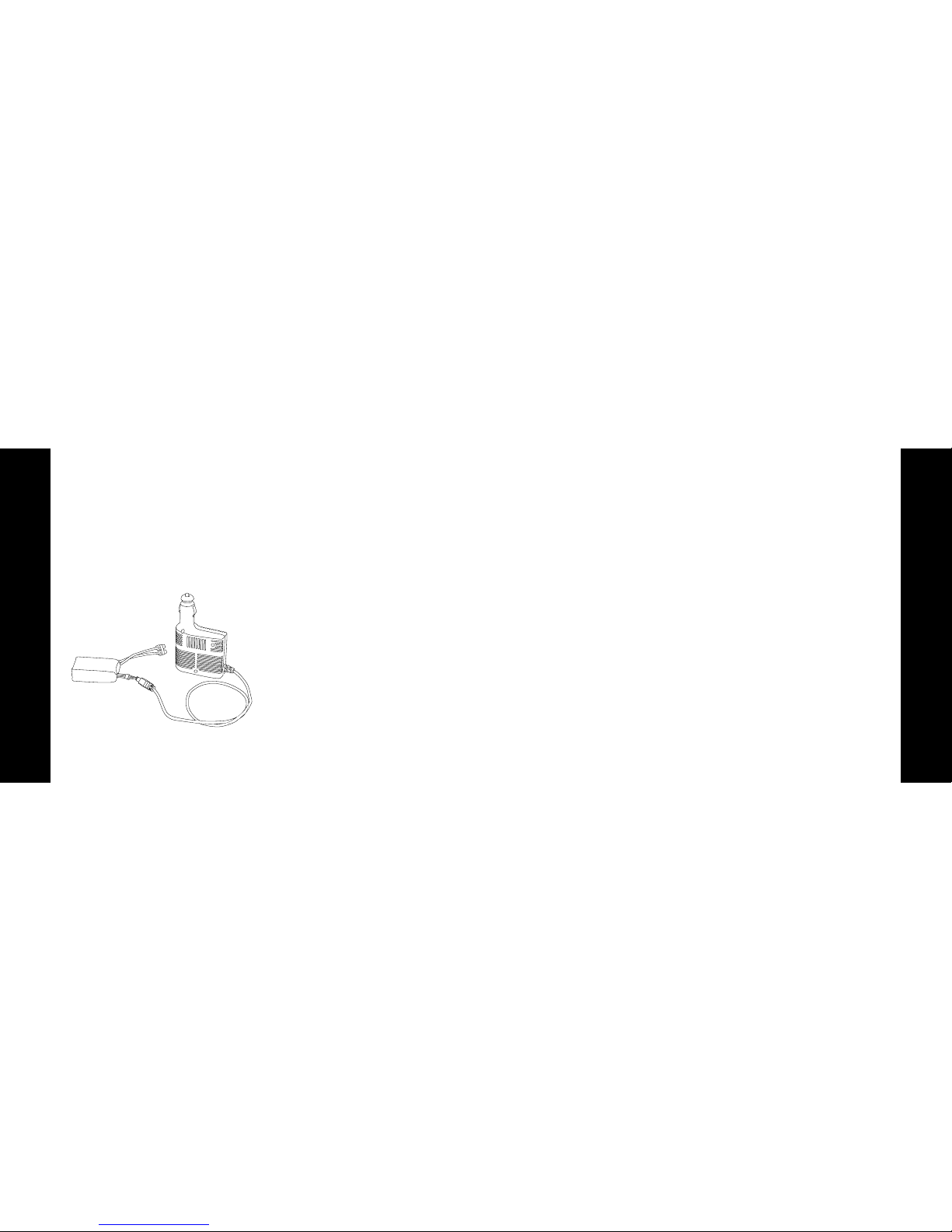
Charging the Aircraft Battery
The charger included with your
Super Cub LP uses unique circuitry that
ensures an accurate charge every time
and protects your Li-Po battery from the
dangers of overcharging. This charger
continually monitors the battery and
automatically stops charging when the
battery is fully charged.
DC Li-Po Balancing Charger Features
• Charges 3-cell lithium polymer
battery packs at 1.3-amps
• LED charge status indicator
• 12V accessory outlet input cord
You must charge the included Li-Po
battery pack with a Li-Po specific
charger only (such as the included
charger). Never leave the battery and
charger unattended during the charge
process. Failure to follow the
instructions properly could result in a
fire. When charging, make certain the
battery is on a heat-resistant surface.
1. The 12V DC 3S Li-Po balancing
charger provides a charge current
of approximately 1.3-amps. The
typical charge time for the
included 11.1V 1300mAh Li-Po is
approximately 1 hour.
2. Locate the safety charge lead on the
battery pack. Connect the battery
pack to the charger. Charge through
the balance lead on the battery
pack. The blue EC3 connector will
remain disconnected when using the
included charger.
3. Connect the charger to either a 12V
power outlet in a vehicle or the AC
adapter included with your Super
Cub LP. Please note that some 12V
outlets require your vehicle to be
running for the outlet to be
operational. It is recommended to
consult your vehicle owner’s
manual if you are unsure. The LED
will continually blink while the
battery charges. It is not
recommended to charge batteries
while the vehicle is in motion.
4. Charging is finished when the LED
indicator glows steadily.
Page 4
5
Step 2
6
Step 3
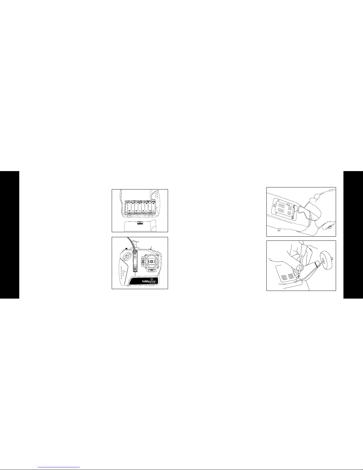
Installation of Batteries into the Transmitter Landing Gear Attachment
1. Remove the battery cover and install
the included 8 AA batteries.
2. Be certain that you observe proper
polarity when installing the
batteries, and then replace the
cover on the transmitter.
3. To test the transmitter’s function,
turn on the switch on the front of the
transmitter. The LED should glow
brightly.
4. Replace the batteries with fresh AA
batteries when you hear the low
voltage battery alarm beeping.
5. Once the alarm goes off, you only
have a few minutes of power left,
so don’t delay landing your plane
any longer than necessary to land it
safely.
1. Locate the included wire landing
gear.
2. Slide the landing gear into the
allotted slot on the bottom of the
fuselage.
3. Make sure the gear is securely in the
slot by gently pulling on it after it is
attached.
4. Attach the white plastic scale covers
with the included four (4) screws as
shown. They are located in the small
bag labeled “A.”
Page 5
7
Step 4
8
Step 5
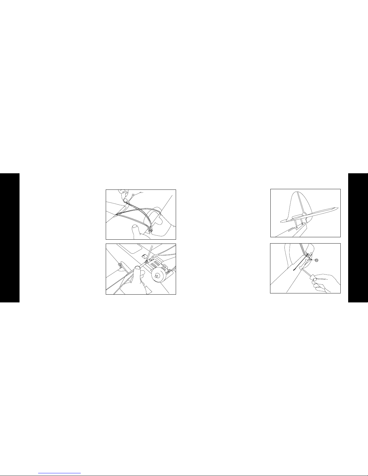
Attaching the Wing Attaching the Tail
1. Locate the wing and strut screws
that are included.
2. Place the wing so that it is centered
on the top of the fuselage.
3. Use the included rubber bands to
secure the wing by attaching two
bands straight across the top of the
wing, where each end is attached
to each set of wing hold-down rods,
and criss-crossing two diagonally
across the top of the wing.
4. After you are satisfied that the wing
is properly centered on the fuselage,
turn the plane over and complete
the wing attachment by attaching
the struts as shown. The screws that
will be used to attach the struts are
in the small bag labeled “B.”
5. Make certain the wing is properly
attached and centered prior to each
flight.
1. Locate the rudder and horizontal
stabilizer assemblies and carefully
remove them from the box.
2. Install the rudder assembly into the
horizontal stabilizer, as shown.
3. Install the complete tail assembly
into the fuselage, as shown.
4. Secure this assembly to the fuselage,
from the bottom, with the included
screws. The two screws needed
for this step are in the small bag
labeled “C” and are the two longest
included.
5. Clip the tail wheel wire into the
plastic wheel housing by pulling
down slightly on the tail wheel, while
at the same time you are pushing up
on the plastic molding until the two
parts “snap” together. Make sure to
support the tail when doing this so
that no damage is done to the aft
fuselage area.
Page 6
9
Step 5
10
Step 6
6. Attach the clevis from the rudder
pushrod into the outermost hole of
the control horn on the rudder, and
slide the clear rubber sleeve down
over the clevis.
7. Attach the clevis from the elevator
pushrod into the outermost hole of
the control horn on the bottom of
the elevator. Slide the clear rubber
sleeve down over the clevis. Again,
refer to the instructional video for a
more detailed explanation.
push up
pull down
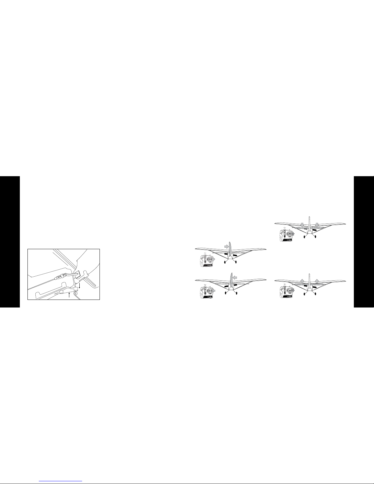
Attaching the Tail (continued) Tail Control Test
1. Make certain the throttle slider is
in the “off” position. Turn on the
transmitter.
2. Install the flight battery in the
fuselage and plug the battery lead
into the lead inside the airplane.
3. Move the stick on the transmitter
(rudder control) side to side while
observing the vertical control surface
is moving per the input (as shown).
Right
Left
4. Push the stick full forward
(elevator control). When this is
done, the horizontal control surface
should move down (as shown),
causing the plane to pitch down.
Down
5. Pull back on the stick (elevator
control). When this is done, the
horizontal control surface should
move up (as shown), causing the
plane to pitch up.
Up
Page 7

11
Step 6
12
Step 7
Tail Control Test (continued) Making Adjustments to the Control Surfaces
6. If your airplane is not responding,
DO NOT FLY IT! Please refer to the
Troubleshooting section at the back
of this manual for more information.
If you still need assistance, call the
Horizon Hobby Support Team at
1-877-504-0233.
7. When you are satisfied your airplane
is set up properly, you can unplug
the flight battery and then turn off
the transmitter. This should be done
every time you have finished flying.
Note: It is very important to make sure
that the control surfaces (rudder and
elevator) are at neutral, or 0 degrees.
Ideally, they will be at neutral when
the levers are centered. The next step
explains how to make adjustments to
the control surface.
1. Any changes necessary to bring
both the rudder and the elevator
to neutral (zero degrees) should be
able to be done by using the trim
levers on the transmitter. To do this,
place the control stick at center, and
use the trim lever below the stick to
adjust the rudder (vertical surface)
until it is in line with the vertical fin.
To adjust the elevator so that it is
in line with the horizontal stabilizer,
use the trim lever to the left of the
control stick.
2. After making adjustments using the
trim levers, if you find you are not
able to position the control surfaces
at neutral, do not fly until things
have been corrected.
3. If corrections are needed and
moving the trim lever(s) is not
adequate, you will need to perform
the following steps:
a. Turn on the transmitter.
b. Insert the battery pack into the
fuselage and plug the battery into
the lead from the airplane.
c. Return the trim levers to center.
d. Remove the clevis from the control
surface horn and adjust the
length of the pushrod by turning the
clevis in the appropriate direction.
Turning clockwise makes the
pushrod shorter and
counterclockwise makes it longer.
Elevator Trim
Rudder Trim
Page 8

13
Step 8
14
Step 9
Choose a Large, Open Grass Field Choose a Calm Day
In order to have the most success, and
to protect property and your Super Cub
LP, it is very important to select a place
to fly that is very open.
The site should:
• Have a minimum of 300 feet
(90 meters) of clear space in ALL
directions.
• Be clear of pedestrians.
• Be free of trees, buildings, cars,
power lines, or anything that could
entangle your airplane or interfere
with your sightline.
• Remember, your Super Cub LP
can reach speeds of up to 30 mph
(48km/h), so it can cover ground
quickly.
• Plan on ying in an area that gives
you more space than you think you
need, especially with first flights.
600 feet
We know you want to fly your Super
Cub LP as soon as you have it. However, flying in too much wind can place
your aircraft in jeopardy. On your first
flights, make sure that the winds are no
more than 5-7 mph (8-11km/h).
To check the wind conditions:
• Tie the red ribbon to the transmitter
antenna.
• Hold the transmitter so the antenna
is parallel to the ground.
If the flag hangs down, it is calm enough
to fly. If the angle between the antenna
and the flag is less than 20 degrees, it
is too windy and you need to postpone
your flight.
too windy
calm
maximum
allowed wind
Page 9

15
Step 10
16
Step 11
Range Test Anti-Crash Technology (ACT)
Prior to your first flight, you will need
to perform a range test. Two people
are needed to do this—one to hold the
airplane and one to hold the transmitter.
1. One person holds the transmitter
while the other person walks 100
paces away with the Super Cub LP.
2. Be sure the throttle slider is in the
“off” position.
3. Extend the antenna and turn on the
transmitter.
4. Plug in the flight battery, close the
battery door and turn the latch so
the battery door stays in place.
5. As soon as the throttle is advanced,
the prop should spin quickly.
6. As the person moves the
transmitter controls, the airplane
should respond correctly with the
controls operating smoothly.
Warning: The person holding the airplane
needs to make sure the propeller
will not come in contact with any
clothing, hair, or parts of the body.
10 0 paces
Your Super Cub LP comes equipped
with exclusive Anti-Crash Technology.
This software will help prevent crashes
due to over-control. The sensors that
are located on the fuselage “see” the
horizon. One sensor is located at the
top of the windshield and the other is
on the bottom side of the fuselage, in
front of the landing gear.
The electronic system connected to the
sensors knows that the airplane (with
ACT
™
“on”) should not be allowed to
enter a steep dive. If you give
transmitter input that causes the plane
to enter into a steep dive that could
lead to a crash, the ACT software will
override your input to help prevent the
aircraft from crashing to the ground.
ACT will cut the power going to the
motor and add some up elevator, as
well. This causes the nose of the
airplane to pull up, thereby helping
to prevent your aircraft from
crashing. However, in order for ACT to
work properly, there has to be sufficient
altitude for recovery (at least 200 feet
or 61 meters). ACT will only interrupt
flight in extreme situations, allowing you
to enjoy as much control of your Super
Cub LP as you need.
Page 10

17
Step 11
18
Step 11
Anti-Crash Technology (ACT) (continued) Anti-Crash Technology (ACT) (continued)
With ACT
Without ACT
If, with ACT on, you enter into a
threatening dive, you will notice the
following:
• You will hear the motor power
decrease as the ACT programming
overrides your input. This slows the
speed of the airplane and will reduce
the risk of a crash.
• The ACT software will give up
elevator input to help pull the nose
up and out of the dive.
• Once the ACT software has been
engaged (takes over), you will not
regain control until after you have
released the steering stick and
returned it to neutral.
Remember, the purpose of Anti-Crash
Technology is to help you learn to fly
properly and smoothly. When ACT is
engaged, it means you have placed
your aircraft in jeopardy. Keeping the
stick more in the middle, and less to the
“corners” of the transmitter, will allow
you to fly more smoothly and prevent
ACT from engaging.
The key is to learn to make minor
movements on the controls. The
transmitter is proportional and is
sensitive to movements of the control
stick. Once you have gained more
experience, and feel comfortable
flying, you can turn off ACT and have
full control at all times. It is possible to
change flight modes (turn ACT on or
off) while in flight, but sufficient altitude
is required.
To turn off ACT, simply move the switch
on the top of the transmitter to the
appropriate position.
ACT Flying Tips
• Never y at too low of an altitude
and expect ACT to save you from a
crash. You must maintain an altitude
of at least 200 feet (61 meters) for the
software to be able to help
prevent crashes.
• Even when ying with ACT on, if you
feel that your aircraft is in jeopardy,
reduce the throttle immediately and
release the stick. You can then add
a small amount of up elevator (pull
back slightly on the stick), as well, to
aid the recovery.
• Because the sensors are used to
activate the protective software,
there may be times when they can be
fooled. This may be especially true
when flying in very bright sunshine
and/or when the sun is close to the
horizon.
• With ACT on, never y over water,
light colored sand, ice, snow or
anything else that can reflect light
and “fool” the sensors.
• Never y in too tight of an area.
Anti-Crash Technology will not
prevent you from crashing into trees,
buildings or other obstacles.
• Make several successful ights
(including several soft landings) prior
to attempting to fly with ACT off.
• Never let the aircraft y too far
downwind from you, which can cause
the aircraft to fly away.
• It is always a good idea to have an
experienced pilot who has mastered
control with at least a 3-channel
radio system to help you on your first
flights.
Page 11

19
Step 12
20
Step 13
Using Elevator (Pitch Control) Hand Launch
Your Super Cub LP is equipped with a
third channel for pitch control (elevator).
Pulling back on the transmitter stick will
cause the nose of the airplane to raise
and allows for tighter turns, shorter
runway takeoffs, flares for landing, a
better climb rate and the ability to
perform aerobatic maneuvers, such as
loops and stalls. However, giving too
much UP elevator (pulling back too
much on the stick) can also place
your aircraft in jeopardy, as your
airplane can enter an unplanned stall,
especially when the plane is traveling at
slower speeds.
Just after a stall occurs, the nose of the
airplane will go down, and the airplane
will begin to enter a dive. To recover
from a stall, pull the stick back slowly
(UP elevator) to pull the nose up and
out of the dive. This should return the
airplane to straight and level flight. Be
careful as pulling back too quickly or
too far will once again cause the plane
to enter a stall.
On first flights, it is a good idea to have
a second person, ideally an adult, help
you launch the plane. This will allow
you to focus entirely on the transmitter
input.
1. Make sure the battery is fully
charged.
2. Make certain that no one is flying,
or preparing to fly, on the same
channel within approximately ½ mile
(.8 kilometers). If someone were to
turn on a transmitter on the same
frequency as yours, you will lose
control of your airplane. This could
cause damage to your airplane,
cause it to fly away, or cause
property damage to other property
if your airplane were to crash into
it. When you are confident it is safe
to turn on your transmitter, you can
move on to the next step.
3. Power on the transmitter.
4. Install and plug in the flight battery.
5. If you are hand launching the aircraft
yourself, place the plane in your
right hand and the transmitter in
your left hand.
6. Use caution and advance the throttle
to FULL.
7. Take a few steps forward, and launch
the airplane DIRECTLY and firmly
into the wind, while keeping the
airplane and its wings level with the
ground.
8. Allow the plane to climb steadily at
full throttle, into the wind, until you
have achieved an altitude of 100 to
150 feet (30 to 46 meters). You will
not need to use elevator in order for
your airplane to climb. A few clicks
down on the elevator trim should
allow a steady climb.
Page 12

21
Step 14
22
Step 15
Runway Takeoff (ROG) Flying
Your Super Cub LP can be launched by
way of a runway takeoff (ROG).
However, this is not recommended for
inexperienced pilots.
1. Make sure your landing gear is
properly installed.
2. Stand behind your Super Cub LP
and point it directly into the wind on
smooth asphalt or concrete.
3. Apply FULL power via the throttle
slider and adjust the control stick
as necessary to keep the aircraft
headed directly into the wind.
4. If the battery is fully charged, your
Super Cub LP should lift off the
ground in approximately 30 feet (12
meters). Apply some UP elevator
by pulling back on the stick, and
the plane will lift off the ground in a
shorter distance. Remember, only a
small amount of UP is needed. Too
much will cause a stall after your
aircraft has left the ground.
1. After you have launched your Super
Cub LP, it will begin climbing at full
throttle. With the throttle advanced
all the way forward, your Super Cub
LP should not need any elevator
input to climb steadily.
2. Make adjustments on the throttle
slider and control stick that are
necessary to keep your aircraft
heading directly into the wind. Do
not attempt a turn until you have
reached a minimum of 50-100 feet
(15.25-30.5 meters) of altitude,
about as tall as a four-story
building.
3. Control range is 2500 feet (762
meters), so if you fly beyond that,
you will lose control of your airplane.
At that distance, however, you would
likely lose sight of your airplane
before you’d lose control.
4. Don’t let your airplane get too far
downwind from you. Always fly with
the airplane UPWIND from you.
Failure to do this could result in a
fly-away! Remember, the wind is
stronger as your plane flies higher in
the air. It’s ok to fly higher, just be
cautious and watch how your plane
reacts to the wind. Most of the time,
you can fly at higher altitudes at halfthrottle. This is great for smooth,
easy flying when you’re first learning
to fly, and conserves battery power.
5. When you have reached higher
altitudes and want to practice using
the elevator, begin with small and
smooth inputs to the transmitter.
Very little input is needed to get the
plane to turn, climb or descend.
6. Avoid long vertical dives, with the
motor on or off, as it can cause a lot
of stress on the aircraft.
Page 13

23
Step 15
24
Step 16
Flying (continued) Throttle Adjustment
7. It may be helpful to fly in smooth
large ovals at higher altitudes so you
can get used to steering the plane
with the nose coming at you. Flying
with the plane coming toward you
takes some practice and is one of
the hardest things to get used to
when you first begin to fly.
Sharp turns: Move the stick in the
direction you want to turn and add a
bit of UP elevator at the same time (pull
back on the stick). The plane will make
a sharper banking turn.
1. When launching, the throttle should
be all the way on.
2. Once you have achieved the
altitude where you want to fly, you
can reduce throttle to about 50%
for cruising. This will also allow for
longer flights.
3. If you want to reduce altitude,
reduce throttle to less than 50%.
4. To increase altitude again, increase
throttle to more than 50%.
Rudder trim: If the Super Cub LP
seems to drift in one direction when the
control stick is in the neutral (centered)
position, gradually move the rudder
trim lever (below the control stick) in the
OPPOSITE direction of the drift. Adjust
until the plane flies straight with the
control stick at neutral.
Elevator trim: If the model “hunts” up
or down, use the trim lever to the left
of the stick to correct this problem. If it
hunts up, slide the left trim lever up one
notch at a time until it flies level. The
model should fly straight with the stick
at neutral. Your Super Cub LP should
have a steady climb at full throttle when
it is trimmed properly.
Note: If you’re flying with the motor off, or at
a slow speed, allow the Super Cub LP a
bit more area for turns.
Full Throttle
Full Throttle
50% Throttle
Reduced Throttle
Page 14

25
Step 17
26
Step 18
Landing Aerobatic Flight
When you notice that your
Super Cub LP no longer climbs well
under full power, normally after about
10-12 minutes, the battery is getting
low and it is time to land. Line the
airplane up directly into the wind
toward the desired landing spot. At
about 10-15 feet (3-4.5 meters) of
altitude, reduce the throttle gradually
until it is completely shut off. Your
airplane will glide in for a landing.
Auto Cutoff: When the battery gets low
enough, this feature will automatically
shut off the motor and save enough
battery power to maintain control of the
tail so you can land correctly and safely.
If the motor cuts off, prepare to land
immediately. If you are gliding down
and have some time to rest the battery,
you may re-arm the motor by moving
the throttle slider back to off and then
advancing it again. This will only allow
the motor to run briefly, and may allow
you to better adjust your landing. Do
not re-arm the motor more than once.
Warning: Do not attempt to catch the
airplane or injury may occur. Turn
the motor off prior to touchdown
in order to prevent damage to the
wing and/or propeller.
Expert Tip: As you get more experienced at
flying, try adding a small amount
of UP elevator just before
touchdown to “flare” the
airplane. With more and more
practice, your landings will be
smooth and on target.
10 FT
Reduce power at 10 feet
It is recommended in the instructions
that the Super Cub LP controls be set
for softer responses and at the outer
holes of the control surfaces. However,
once you get used to the flight
characteristics and want to perform
more aerobatic maneuvers (with ACT
off), you can change the amount of
throw that is permitted by moving the
clevises to the inner holes of the control
horns. After making any adjustments,
always turn on the transmitter, center
the transmitter trim levers and make
sure the control surfaces are even.
Make the proper adjustments to make
the surfaces even, if they are not (see
Step 7).
Note: By making these changes, the
controls will be much more
responsive. However, this makes the
airplane much less forgiving and it will
be easier to stall. Remember, crash
damage is not covered under the
warranty.
Page 15

27 28
Optional Floats Repairing Minor Damage
If you happen to crash, and part of the
tail or wing breaks, it can be repaired
by using packing tape to cover the
missing pieces. Also, any type of CA
will help repair the foam fuselage and
wing. However, if damage is severe, or
if the wing and/or tail are bent, replace
the damaged parts prior to flying again.
There is a complete list of replacement
parts in the back of this manual.
Replace wing immediately
Once you are an accomplished pilot
and you are ready for the next exciting
challenge, you may want to try the thrill
of float flying. The Super Cub LP has the
mounts installed for the optional
HobbyZone Super Cub LP floats
(HBZ7390). Refer to the float manual for
installation and tips on float flying.
Page 16

29 30
8. After you have finished flying, or at
any time you have the radio system
on, ALWAYS unplug the battery
prior to turning the transmitter off.
ALWAYS turn on the transmitter
prior to plugging the flight battery
in.
9. Never fly on the same frequency
as another RC vehicle in your area.
Doing so will cause you, or the
other person, to lose control of your
plane.
Warnings and Safety Checklist
1. Read and follow this manual and the
included DVD completely, observing
all instructions and safety directions.
If you do not do this, serious injury
and damage can occur. Think about
safety first.
2. Keep the propeller away from all
body parts at all times! Beware of
loose clothing or hair becoming
entangled in the propeller.
3. Never fly when it is too windy or you
may lose control of the airplane.
Never fly near people, vehicles, train
tracks, buildings, power lines, water
or trees, and never attempt to catch
the airplane.
4. Age Recommendation: 14 years or
over. This is not a toy. This product is
not intended for use by children
without direct adult supervision.
5. Only use a LiPo battery charger that
is compatible for use with the Super
Cub LP battery. We recommend using the charger that comes with your
airplane. Never leave the chargers
unattended while charging!
During charging, place the battery
and charger on a heat-resistant
surface. Do not place them on
carpet or upholstery.
6. Never cut into the battery charger or
airplane wires, or serious injury can
occur. Causing the battery to short
out (crossing negative and positive
bare wires) can cause a fire, serious
injury and damage.
7. Hold the plane securely, and keep
all body parts away from the
propeller at all times. Carry the
plane as though the propeller could
start spinning at any time when you
have the battery pack plugged into
the lead from the plane.
Page 17

31 32
Troubleshooting
Unit does not operate 1. Transmitter AA batteries are depleted
or installed incorrectly as indicated by a
dim or unlit LED on the transmitter or the
low battery alarm
2. No electrical connection
3. Flight battery is not charged
4. Crash has damaged the radio inside
the fuselage
1. Check polarity installation or replace with
fresh AA batteries
2. Push connectors together until they click
3. Fully charge the battery
4. Replace the fuselage or receiver
Aircraft keeps turning in
one direction
1. Rudder or rudder trim is not adjusted
correctly
2. Wing is not centered over the fuselage
1. Adjust stick trim lever or adjust rudder
position (see page 14)
2. Center the wing
Aircraft is difficult
to control
1. Wing or tail is damaged 1. Replace damaged part
Aircraft keeps pitching
up steeply
1. Wind is too gusty or strong
2. Elevator is trimmed 'up' too much
1. Postpone flying until the wind calms down
2. Adjust elevator trim 'down'
Motor cuts in and out
1. ACT is on (make sure it is intended to
be on)
2. ACT is on but due to reflective surfaces
and dark sky, ACT is not working correctly
3. ACT is on, and sun is low on the horizon
Aircraft won't climb 1. Battery is not fully charged
2. Elevator may be trimmed 'down'
1. Charge battery fully shortly before flying
2. Adjust elevator trim 'up' (see page 14)
1. Turn ACT off
2. Turn ACT off and if ACT is needed,
postpone flying until conditions improve
3. Turn ACT off, and postpone using ACT until
sun is higher in the sky
PROBLEM
POSSIBLE CAUSE
SOLUTION
Success Tips
gently to level flight and level the
wings.
4. Don’t attempt to fly or do
maneuvers beyond your flying
abilities without seeking the
assistance of an experienced pilot.
5. If you’re gliding with the motor off,
allow the Super Cub LP more area
for turns.
6. Position yourself at your flying field
to keep the sun at your back and
out of your eyes. Wear sunglasses
on bright days.
7. Keep the Super Cub LP upwind,
especially on windier days, to
prevent it from “flying away.” The
wind is normally stronger at higher
altitudes than it is on the ground.
8. Keep your plane in front of you so
you don’t have to turn in circles as
you fly. Try to avoid flying directly
overhead.
1. Don’t fly in winds over 7 mph
(11km/h). First-time pilots should
get help from an experienced radio
control pilot during first flights.
2. Choose your flying field carefully—
grass and soft ground with a 600foot (183-meter) diameter of open
space is optimal for flying and will
lengthen the life of the Super Cub
LP. Make sure there are no obstacles that will get in your way when
flying, such as trees or buildings.
Make sure you do not fly where
there are pedestrians who could be
hurt by the airplane.
3. Remember that holding the stick
full over for too long can cause the
airplane to spiral dive and crash. At
the very first sign of the Super Cub
LP beginning to spiral down,
immediately release the stick and
give the opposite turn control to the
spiral, then pull back on the elevator
Page 18

33 34
PART# DESCRIPTION RETAIL PART# DESCRIPTION RETAIL
HBZ7310 Decal Sheet: Super Cub LP $3.99
HBZ7351 ESC/Receiver Ch. 1 $26.99
HBZ7352 ESC/Receiver Ch. 2 $26.99
HBZ7353 ESC/Receiver Ch. 3 $26.99
HBZ7354 ESC/Receiver Ch. 4 $26.99
HBZ7355 ESC/Receiver Ch. 5 $26.99
HBZ7356 ESC/Receiver Ch. 6 $26.99
HBZ7361 Fuselage
w/Electronics, Ch. 1 $73.99
HBZ7362 Fuselage
w/Electronics, Ch. 2 $73.99
HBZ7363 Fuselage
w/Electronics, Ch. 3 $73.99
HBZ7364 Fuselage
w/Electronics, Ch. 4 $73.99
HBZ7365 Fuselage
w/Electronics, Ch. 5 $73.99
HBZ7366 Fuselage
w/Electronics, Ch. 6 $73.99
PKZ1130 Mini Servo (5W) with Arms $9.99
PKZ1131 Servo Gear Set $2.49
PKZ1132 Servo Arm Assortment $1.59
Optional Parts
HBZ4020 Sonic Combat Module $23.99
HBZ6023 Aerial Drop Module $19.99
HBZ7390 Super Cub LP Floats $24.99
PART# DESCRIPTION RETAIL PART# DESCRIPTION RETAIL
PKZ1005 10 x 8 High Power Propeller
(for use with optional floats) $3.49
EFLAEC312 EC3 Charge Lead w/12”
Wire & Jacks,16AWG $ 6.99
Replacement Parts
PART# DESCRIPTION RETAIL PART# DESCRIPTION RETAIL
HBZ1002 9 x 6 Propeller $3.49
HBZ1003 DC LiPo Balancing Charger $19.99
HBZ1004 1.5A AC Power Supply $19.99
PKZ1033 1300mAh 11.1V Li-Po Battery
with EC3 Connector $41.99
HBZ1058 Transmitter Antenna $4.99
HBZ6057 Transmitter Battery Cover $2.50
HBZ7071 Transmitter, Ch. 1, 26.995 $32.99
HBZ7072 Transmitter, Ch. 2, 27.045 $32.99
HBZ7073 Transmitter, Ch. 3, 27.095 $32.99
HBZ7074 Transmitter, Ch. 4, 27.145 $32.99
HBZ7075 Transmitter, Ch. 5, 27.195 $32.99
HBZ7076 Transmitter, Ch. 6, 27.255 $32.99
HBZ7104 Prop Shaft $2.49
HBZ7106 Landing Gear with Tires $5.99
HBZ7107 Spinner $0.99
HBZ7112 Battery Door with Latch $1.99
HBZ7114 Firewall with Screws $1.79
HBZ7117 Tail Wheel $2.99
HBZ7120 Standard Wing with Struts $19.99
HBZ7121 Control Horns (4) $1.29
HBZ7122 Wing Struts with Screws $2.19
HBZ7124 2 Wing Hold Down Rods $1.49
HBZ7125 Tail with Accessories $11.99
HBZ7126 Cowl $2.99
HBZ7127 White Rubber Bands $0.99
HBZ7128 Pushrods and Clevis Set $0.99
HBZ7129 Gearbox with Firewall $8.99
HBZ7134 Motor with Pinion $10.99
PKZ1536 Motor Screws (2): M 2.5 x 6 $0.99
HBZ7135 Metal Pinion (2) $0.99
HBZ7185 Bare Fuselage (no receiver) $20.99
Replacement parts are available at your local hobby shop or www.horizonhobby.com.
Page 19

35 36
damage due to acts of God, accident,
misuse, abuse, negligence,
commercial use, or modification of or to
any part of the Product. This warranty
does not cover damage due to
improper installation, operation,
maintenance, or attempted repair by
anyone other than Horizon. Return of
any goods by Purchaser must be
approved in writing by Horizon before
shipment.
Damage Limits
HORIZON SHALL NOT BE LIABLE FOR
SPECIAL, INDIRECT OR
CONSEQUENTIAL DAMAGES, LOSS
OF PROFITS OR PRODUCTION OR
COMMERCIAL LOSS IN ANY WAY
CONNECTED WITH THE PRODUCT,
WHETHER SUCH CLAIM IS BASED IN
CONTRACT, WARRANTY,
NEGLIGENCE, OR STRICT LIABILITY.
Further, in no event shall the liability of
Horizon exceed the individual price of
the Product on which liability is
asserted. As Horizon has no control over
use, setup, final assembly, modification
or misuse, no liability shall be assumed
nor accepted for any resulting damage
or injury. By the act of use, setup or
assembly, the user accepts all resulting
liability.
If you as the Purchaser or user are not
prepared to accept the liability
associated with the use of this Product,
you are advised to return this Product
immediately in new and unused
condition to the place of purchase.
Law: These Terms are governed by
Illinois law (without regard to conflict of
law principals).
Safety Precautions
This is a sophisticated hobby Product
and not a toy. It must be operated
with caution and common sense and
requires some basic mechanical ability.
Failure to operate this Product in a safe
and responsible manner could result in
injury or damage to the Product or other
Warranty
Warranty Period
Exclusive Warranty- Horizon Hobby, Inc.,
(Horizon) warranties that the Products
purchased (the “Product”) will be free
from defects in materials and
workmanship at the date of purchase by
the Purchaser.
Limited Warranty
(a) This warranty is limited to the original
Purchaser (“Purchaser”) and is not
transferable. REPAIR OR REPLACEMENT AS PROVIDED UNDER THIS
WARRANTY IS THE EXCLUSIVE
REMEDY OF THE PURCHASER. This
warranty covers only those Products
purchased from an authorized Horizon
dealer. Third party transactions are
not covered by this warranty. Proof of
purchase is required for warranty claims.
Further, Horizon reserves the right to
change or modify this warranty without
notice and disclaims all other warranties,
express or implied.
(b) Limitations- HORIZON MAKES NO
WARRANTY OR REPRESENTATION,
EXPRESS OR IMPLIED, ABOUT NONINFRINGEMENT, MERCHANTABILITY
OR FITNESS FOR A PARTICULAR
PURPOSE OF THE PRODUCT. THE
PURCHASER ACKNOWLEDGES THAT
THEY ALONE HAVE DETERMINED
THAT THE PRODUCT WILL SUITABLY
MEET THE REQUIREMENTS OF THE
PURCHASER’S INTENDED USE.
(c) Purchaser Remedy- Horizon’s sole
obligation hereunder shall be that
Horizon will, at its option, (i) repair or
(ii) replace, any Product determined by
Horizon to be defective. In the event
of a defect, these are the Purchaser’s
exclusive remedies. Horizon reserves the
right to inspect any and all equipment
involved in a warranty claim. Repair or
replacement decisions are at the sole
discretion of Horizon. This warranty
does not cover cosmetic damage or
Page 20

37 38
sales receipt must also be included for
warranty consideration. Be sure your
name, address, and RMA number are
clearly written on the outside of the
shipping carton.
Warranty Inspection and Repairs
To receive warranty service, you must
include your original sales receipt
verifying the proof-of-purchase date.
Provided warranty conditions have been
met, your Product will be repaired or
replaced free of charge. Repair or
replacement decisions are at the sole
discretion of Horizon Hobby.
Non-Warranty Repairs
Should your repair not be covered by
warranty the repair will be completed
and payment will be required without
notification or estimate of the expense
unless the expense exceeds 50% of the
retail purchase cost. By submitting the
item for repair you are agreeing to
payment of the repair without
notification. Repair estimates are
available upon request. You must
include this request with your repair.
Non-warranty repair estimates will be
billed a minimum of ½ hour of
labor. In addition you will be billed for
return freight. Please advise us of your
preferred method of payment. Horizon
accepts money orders and cashiers
checks, as well as Visa, MasterCard,
American Express, and Discover cards.
If you choose to pay by credit card,
please include your credit card number
and expiration date. Any repair left
unpaid or unclaimed after 90 days will
be considered abandoned and will be
disposed of accordingly. Please note:
non-warranty repair is only available on
electronics and model engines.
property. This Product is not intended
for use by children without direct adult
supervision. The Product manual contains instructions for safety, operation
and maintenance. It is essential to read
and follow all the instructions and warnings in the manual, prior to assembly,
setup or use, in order to operate correctly and avoid damage or injury.
Questions, Assistance, and Repairs
Your local hobby store and/or place of
purchase cannot provide warranty
support or repair. Once assembly, setup
or use of the Product has been started,
you must contact Horizon directly. This
will enable Horizon to better answer
your questions and service you in the
event that you may need any assistance.
For questions or assistance, please
direct your email to
productsupport@horizonhobby.com, or
call 877.504.0233 toll free to speak to a
service technician.
Inspection or Repairs
If this Product needs to be inspected or
repaired, please call for a Return
Merchandise Authorization (RMA). Pack
the Product securely using a shipping
carton. Please note that original boxes
may be included, but are not designed
to withstand the rigors of shipping
without additional protection. Ship via a
carrier that provides tracking and
insurance for lost or damaged parcels,
as Horizon is not responsible for
merchandise until it arrives and is
accepted at our facility. A Service Repair
Request is available at
www.horizonhobby.com on the
“Support” tab. If you do not have
internet access, please include a letter
with your complete name, street
address, email address and phone
number where you can be reached
during business days, your RMA
number, a list of the included items,
method of payment for any
non-warranty expenses and a brief
summary of the problem. Your original
Page 21

39 40
This product must not be disposed of with other waste. Instead, it is the
user’s responsibility to dispose of their waste equipment by handing it
over to a designated collections point for the recycling of waste
electrical and electronic equipment. The separate collection and
recycling of your waste equipment at the time of disposal will help to
conserve natural resources and ensure that it is recycled in a manner
that protects human health and the environment. For more information
about where you can drop off your waste equipment for recycling, please contact
your local city office, your household waste disposal service or where you purchased
the product.
Instructions for Disposal of WEEE by Users in the European Union
CE Compliance Information for the European Union
United States
Electronics and engines requiring
inspection or repair should be shipped
to the following address:
Horizon Service Center
4105 Fieldstone Road
Champaign, Illinois 61822
All other Products requiring warranty
inspection or repair should be shipped
to the following address:
Horizon Product Support
4105 Fieldstone Road
Champaign, Illinois 61822
Please call 877-504-0233 or e-mail us
at productsupport@horizonhobby.com
with any questions or concerns
regarding this product or warranty.
United Kingdom
Electronics and engines requiring
inspection or repair should be shipped
to the following address:
Horizon Hobby UK
Units 1-4 Ployters Rd
Staple Tye
Harlow, Essex
CM18 7NS
United Kingdom
Please call +44 (0) 1279 641 097 or
e-mail us at sales@horizonhobby.co.uk
with any questions or concerns
regarding this product or warranty.
Germany
Electronics and engines requiring
inspection or repair should be shipped
to the following address:
Horizon Technischer Service
Hamburger Strasse 10
25335 Elmshorn
Germany
Please call +49 4121 46199 66 or e-mail
us at service@horizonhobby.de with any
questions or concerns regarding this
product or warranty.
Page 22

41 42
(in accordance with ISO/IEC 17050-1)
No. HH20090202
Product(s): Super Cub LP RTF
Item Number(s): HBZ7300
Equipment class: 1
The objects of declaration described above are in conformity with the requirements
of the specifications listed below, following the provisions of the European R&TTE
directive 1999/5/EC:
EN 301 489-1 v.1.6.1 General EMC requirements
EN 301 489-17 v.1.2.1
Signed for and on behalf of:
Horizon Hobby, Inc.
Champaign, IL USA
Feb 02, 2009
Declaration of Conformity
Steven A. Hall
Vice President
International Operations and
Risk Management
Horizon Hobby, Inc.
 Loading...