

Page 1

Instruction Manual
Bedienungsanleitung
Manuel d’utilisation
Manuale di istruzioni
Page 2
2
HobbyZone Super Cub • Instruction Manual
WARNING: Read the ENTIRE instruction manual to become familiar with the features of the product before operating. Failure to operate the product correctly can
result in damage to the product, personal property and cause serious injury.
This is a sophisticated hobby product. It must be operated with caution and common sense and requires some basic mechanical ability. Failure to operate this Product
in a safe and responsible manner could result in injury or damage to the product or other property. This product is not intended for use by children without direct adult
supervision. Do not attempt disassembly, use with incompatible components or augment product in any way without the approval of Horizon Hobby, Inc. This manual
contains instructions for safety, operation and maintenance. It is essential to read and follow all the instructions and warnings in the manual, prior to assembly, setup or
use, in order to operate correctly and avoid damage or serious injury.
Additional Safety Precautions and Warnings
Age Recommendation: Not for children under 14 years. This is not a toy.
• Always keep a safe distance in all directions around your model to avoid colli-
sions or injury. This model is controlled by a radio signal subject to interference
from many sources outside your control. Interference can cause momentary loss
of control
• Always operate your model in open spaces away from full-size vehicles, trafc
and people.
• Always carefully follow the directions and warnings for this and any optional sup-
port equipment (chargers, rechargeable battery packs, etc.).
• Always keep all chemicals, small parts and anything electrical out of the reach of
children.
• Always avoid water exposure to all equipment not specically designed and
protected for this purpose. Moisture causes damage to electronics.
• Never place any portion of the model in your mouth as it could cause serious
injury or even death.
• Never operate your model with low transmitter batteries.
The following terms are used throughout the product literature to indicate various levels of potential harm when operating this product:
NOTICE: Procedures, which if not properly followed, create a possibility of physical property damage AND a little or no possibility of injury.
CAUTION: Procedures, which if not properly followed, create the probability of physical property damage AND a possibility of serious injury.
WARNING: Procedures, which if not properly followed, create the probability of property damage, collateral damage, and serious injury OR create a high probability of
supercial injury.
NOTICE
All instructions, warranties and other collateral documents are subject to change at the sole discretion of Horizon Hobby, Inc. For up-to-date product literature, visit
horizonhobby.com and click on the support tab for this product.
Meaning of Special Language
Page 3

3
HobbyZone Super Cub • Instruction Manual
Thank you for purchasing this HobbyZone® Super Cub DSM. Please charge the battery, read this manual, and attach the wing, tail and landing gear. While you charge
the battery, please watch the included DVD, which shows you how to y this model.
This Super Cub DSM helps you teach yourself to y using innovative Anti-Crash Technology™ (ACT), which uses two sensors on the model. The sensors connect to the
model’s control board to detect light from the sky and less light from the ground when the model ies straight and level. When the model dives, ACT corrects the model’s
ight, giving you time to get control. After your ying skill and condence increase, you can disable the ACT to increase your fun.
Please visit www.horizonhobby.com for more information about the Super Cub DSM and other products.
Table of Contents
Battery Warnings .................................................4
Charge the Aircraft Battery ................................... 5
Install Transmitter Batteries ................................... 5
Hi/Lo Rate ...........................................................7
Trainer................................................................. 7
Antenna .............................................................. 8
First Flight Preparation .........................................9
Maintenance After Flying ...................................... 9
Attach Tail ......................................................... 10
Installing Clevises on Control Horns
and Control Centering ........................................ 10
Install Landing Gear ...........................................11
Attach Wing ...................................................... 11
Using Elevator (Pitch Control) ............................. 12
Tail Control Test ................................................. 13
Range Test ........................................................ 14
Choose a Flying Field .........................................15
Flying Conditions ................................................ 15
Simulator Use .................................................... 15
Hand Launch ..................................................... 16
Runway Takeoff .................................................. 16
Anti-Crash Technology (ACT) ............................... 17
Flying ................................................................ 18
Landing ............................................................. 19
Repairing Minor Damage .................................... 19
Throttle Adjustment ............................................ 20
Aerobatic Flight .................................................. 20
Service of Power Components ............................ 21
Disassembly ...................................................... 21
Assembly .......................................................... 21
Troubleshooting Guide ........................................ 22
Replacement Parts ............................................. 24
Optional Parts .................................................... 24
AMA National Model Aircraft Safety Code ........... 25
Warranty and Repair Policy ................................ 26
Warranty and Service Contact Information ........... 27
Parts Contact Information ................................... 27
FCC Information .................................................27
Compliance Information for the European Union ... 28
Specifications
Wingspan 47.7 in (1200mm)
Length 32.5 in (825mm)
Flying Weight 25.2 oz (715 g)
Propeller Size 9 x 6
Components
Motor 480 Brushed (installed)
Battery
3S 11.1V 1300mAh Li-Po
(included)
Charger
DC-powered 3S Li-Po balancing
charger (included)
Transmitter
Spektrum DX4e 4-channel Radio with AA Batteries (included)
Receiver/ESC 2.4GHz DSM receiver/ESC
Page 4
4
HobbyZone Super Cub • Instruction Manual
Battery Warnings
The Battery Charger included with your aircraft is designed to safely charge the
Li-Po battery.
CAUTION: All instructions and warnings must be followed exactly.
Mishandling of Li-Po batteries can result in a re, personal injury, and/or
property damage.
• By handling, charging or using the included Li-Po battery you assume all risks
associated with lithium batteries.
• If at any time the battery begins to balloon or swell, discontinue use
immediately. If charging or discharging, discontinue and disconnect.
Continuing to use, charge or discharge a battery that is ballooning or swelling
can result in re.
• Always store the battery at room temperature in a dry area for best results.
• Always transport or temporarily store the battery in a temperature range of
40–120º F. Do not store battery or model in a car or direct sunlight. If stored
in a hot car, the battery can be damaged or even catch re.
• NEVER USE AN Ni-Cd OR Ni-MH CHARGER. Failure to charge the battery
with a compatible charger may cause re resulting in personal injury and/or
property damage.
• Never discharge Li-Po cells to below 3V under load.
• Never cover warning labels with hook and loop strips.
• Never plug the white balancing lead of the battery pack into anything other
than the included charger
• DO NOT plug into the X-Port socket of the fuselage.
Warnings and Safety Checklist
• Always keep body parts, clothing, jewelry and hair away from the propeller.
• Never y when wind is more than 7 mph (11km/h) or the model may be carried by the wind away from transmitter control.
• Never try to catch a moving model.
• Always use only the included charger to charger your LiPo battery.
• Carefully hold the model and keep all body parts away from the propeller at all
times. When battery is connected to the model, carry the model prepared for
the propeller to turn at any time.
• After ying or at any time you have the transmitter powered on, ALWAYS
disconnect the model from the battery before powering off the transmitter.
• ALWAYS power on the transmitter before connecting the model to the battery.
• Never y when someone else is using the same frequency as your transmitter.
Trying to control several models using only one frequency can result in injury,
damage or loss of model control.
Page 5
5
HobbyZone Super Cub • Instruction Manual
Charge the Aircraft Battery
The Super Cub LP Li-Po battery charger charges every cell correctly and protects
your Li-Po battery from the dangers of overcharging. This charger monitors the
battery’s charge and stops charging when the battery is fully charged.
Charge the included Li-Po battery pack only with a Li-Po battery charger capable
of balance charging.
CAUTION: Never leave the battery and charger unattended when charging a battery. When charging, make certain the battery is on a heatresistant surface. Failure to obey instructions can result in a re.
1. The 12V DC 3S Li-Po balancing charger uses a charge current of approximately 1.3-amps. This charges the included 11.1V 1300mAh Li-Po battery in
approximately 1 hour.
2. Connect the battery pack to the charger using the small white balance charging connector.
NOTICE: Do not connect the blue EC3 power connector when
charging the battery.
3. Connect the charger to the AC adapter (included with your model) and to
a power outlet, or to a vehicle outlet adapter and a 12V power outlet in a
vehicle. When connected to a power source, the charger’s LED blinks while
charging a Li-Po battery.
Note: Please consult your vehicle owner’s manual before connecting the
charger because some vehicle outlets only operate when the vehicle’s engine is operating. Do not move the vehicle while charging Li-Po batteries.
4. The charger’s LED illuminates continuously when the battery is fully charged.
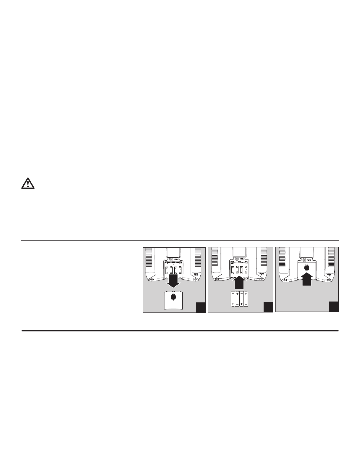
Install Transmitter Batteries
This transmitter requires 4 AA batteries.
1. Remove battery cover from the back of the transmitter.
2. Install batteries as shown where batteries t.
3. Install battery cover.
1
3
2
Page 6
6
HobbyZone Super Cub • Instruction Manual
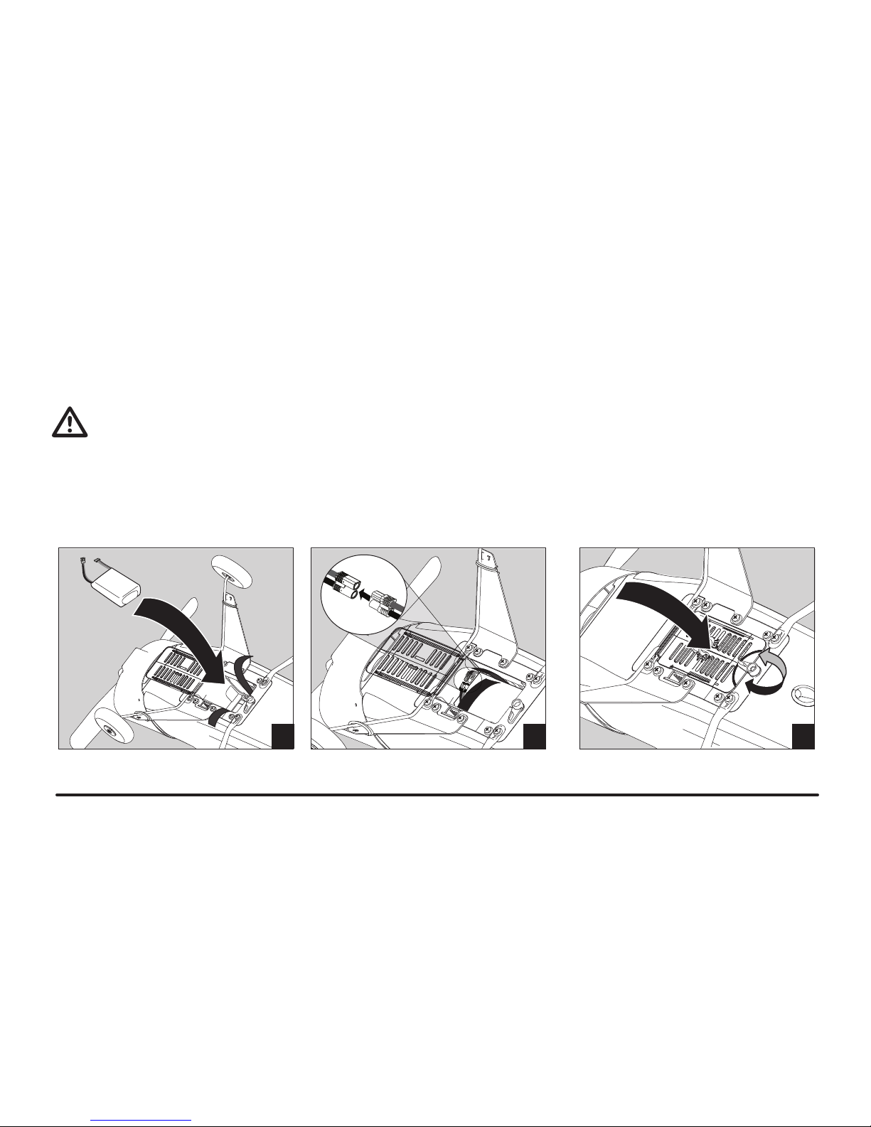
Install Battery in Model
The battery for your Super Cub LP has a blue EC3™ power connector and a
small white balance charging connector. Always connect only the blue connector
to your model.
WARNING: Only connect the white balance charging connector to a
battery charger. NEVER connect to X-Port receptacle on the bottom of
the fuselage or the model will be damaged.
Keep the X-Port socket covered except when in use with approved accessories.
See X-Port information in this manual for use of available accessories.
1. Move the battery door latch and open the battery door on the bottom of the
fuselage.
2. Carefully put battery in battery compartment.
3. Close the hook and loop strap over the battery.
4. When ready to bind or operate the model, connect the blue EC3 battery
connectors in the model.
5. Close the battery door and move the latch to keep the door closed.
1
3
2
Page 7
7
HobbyZone Super Cub • Instruction Manual
Hi/Lo Rate
The DX4e offers a high/low rate function on aileron, elevator and rudder channels.
When the HI/LO rate switch is in the upper, or “HI” position, travel is 100% on
these channels. When the switch is in the lower, or “LO”, position, travel decreases
to 70% on these channels. This switch lets you quickly change control rates from
high for aggressive maneuvers to low for smooth, precise maneuvers.
You should y the Super Cub at the low (70%) rate when you are rst learning to
y the Super Cub.
There may be a small amount of movement in the aileron and rudder (assigned
to the aileron channel) position on the Super Cub when you change rates. This is
caused by the trim switches on the DX4e and the amount of trim you set on each
channel. To decrease this movement, mechanically adjust the linkages on your
aircraft so the trims are as close to center (neutral) as possible.
Trainer
The DX4e offers a trainer function that allows the transmitter to operate as a
master or slave. Refer to the transmitter manual for more information. Using the
trainer function is helpful for new pilots wanting the assistance of an experienced
pilot when learning to y the Super Cub.
Page 8
8
HobbyZone Super Cub • Instruction Manual
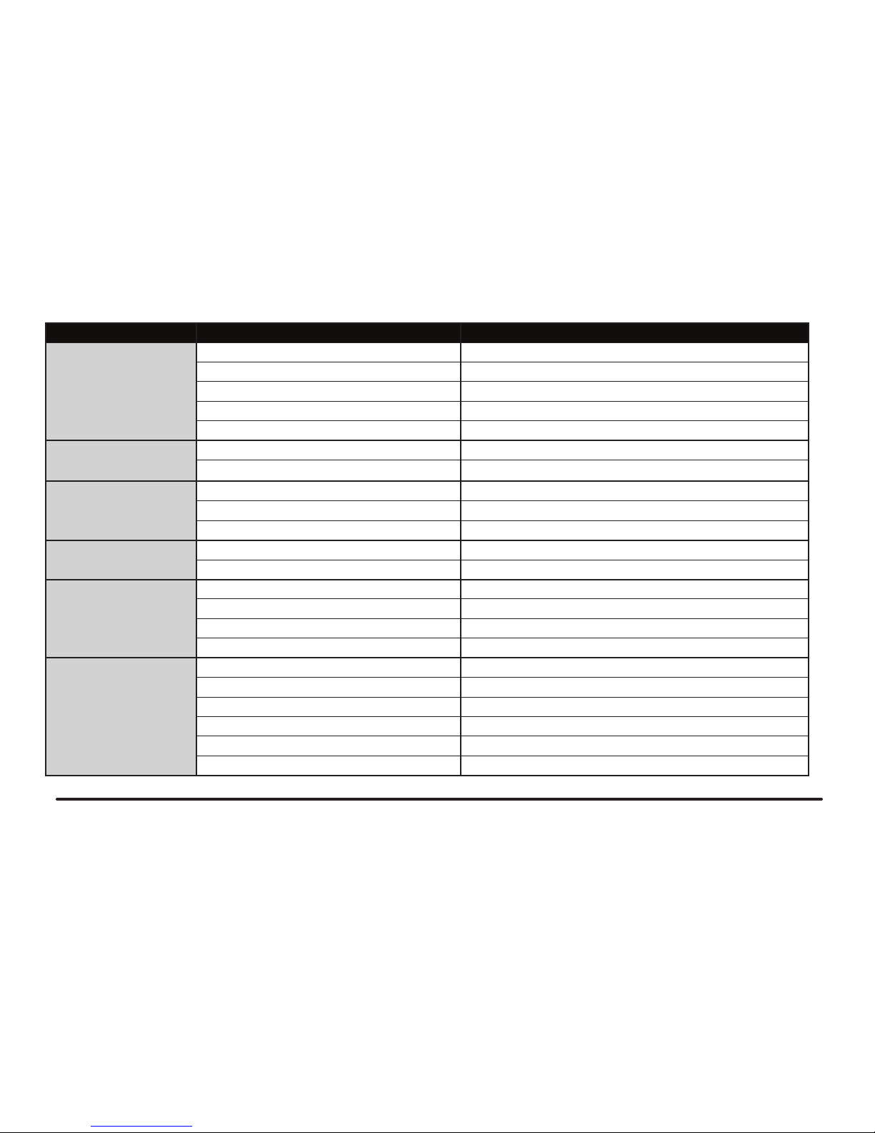
Function
A
Antenna
B
Trainer/Bind (Mode 1)
C
HI/LO Rate Switch
D
Aileron/Elevator Stick (Mode 2)
Aileron/Throttle Stick (Mode 1)
E
Elevator Trim (Mode 2)
Throttle Trim (Mode 1)
F
Aileron Trim
G
Mode Switch
H
Mix Switch
I
Reversing Switches
J
On/Off Switch
K
Rudder Trim
L
Throttle Trim (Mode 2)
Elevator Trim (Mode 1)
M
Throttle/Rudder Stick (Mode 2)
Elevator/Rudder Stick (Mode 1)
N
ACT/AUX Switch
O
Trainer/Bind (Mode 2)
P
LEDs
Q
Trainer Port
R
Battery Cover
TRANSMITTER FUNCTIONS
R
Q
O
P
N
M
L
K
J
I
H
G
F
E
D
C
B
A
Antenna
Do not point the antenna tip at the model.
Signals transmit strongest from the antenna
shaft, not the tip.
WARNING: Do not pick up the
transmitter by the antenna. Do not
alter or put weight on the antenna. Damage to
antenna parts can decrease transmitter signal
strength, which can result in loss of model
control, injury or property damage.
Page 9

9
HobbyZone Super Cub • Instruction Manual
Transmitter and Receiver Binding
Binding is the process of programming the receiver of the control unit to recognize
the GUID (Globally Unique Identier) code of a single specic transmitter. Your
DX4e transmitter comes pre-bound to the aircraft, so binding should not be necessary. Should you need to bind the aircraft and transmitter in the future, please
follow these steps.
First Flight Preparation
• Remove and inspect contents
• Charge ight battery
• Read this instruction manual thoroughly
• Install the ight battery in the aircraft (once it has been fully charged)
• Bind aircraft to your transmitter
• Fully assemble model
• Make sure linkages move freely
• Perform the Control Direction Test with the transmitter
• Adjust ight controls and transmitter
• Perform a radio system Range Check
• Find a safe and open area
• Plan ight for ying eld conditions
Maintenance After Flying
• Disconnect ight battery from model (Required for Safety)
• Power off transmitter
• Remove ight battery from aircraft
• Recharge ight battery
• Repair or replace all damaged parts
• Store ight battery apart from aircraft and monitor the battery charge
• Make note of ight conditions and ight plan results,
planning for future ights
Binding Procedure
1. Make sure DX4e transmitter is powered off.
2. Install a bind plug in the receiver bind port.
3. Connect the ight battery to the ESC. The receiver LED will begin to ash
rapidly.
4. Move the transmitter controls to neutral (ight controls: rudder, elevators and
ailerons) or to low positions (throttle, throttle trim, and ight control trims).*
5. Power on the transmitter while holding the DX4e transmitter bind button.
Release bind button when LEDs ash on the front of the transmitter.
6. When the receiver binds to the transmitter, the LED on the receiver will ash
very quickly. Once the binding process is complete, the ashing will slow.
7. Remove the bind plug from the receiver in the battery compartment. Safely
store the bind plug (some owners attach the bind plug to their transmitter
using two-part loops and clips).
8. Disconnect the ight battery from the ESC then power off the transmitter.
9. Power on the transmitter then connect the ight battery to the ESC.
The LED on the receiver will be solid red.
* The throttle will not arm if the transmitter’s throttle control is not put
at the lowest position.
Page 10

10
HobbyZone Super Cub • Instruction Manual
Attach Tail
1. Put the posts of the rudder in the holes in the top of the horizontal stabilizer.
2. Put the rudder posts in 2 holes in the top of the fuselage tail.
3. Attach the rudder posts under the fuselage using 2 long screws from a small
bag labeled “C”.
Note: Support the tail while installing the tail wheel to prevent damage to
the end of the fuselage.
4. Pull down a small amount on the tail wheel while pushing up the round plastic
housing until the wheel wire goes in the slot in the housing.
5. Push small white bushing on wire of tail wheel in round housing.
6. Connect linkage clevis to the outermost hole of the rudder control horn.
7. Connect linkage clevis to the outermost hole of the elevator control horn.
Note: Please watch the DVD instructional video for more information.
Installing Clevises on Control Horns and Control Centering
Turn the clevis clockwise or counterclockwise on the linkage.
• Pull the tube from the clevis to the linkage.
• Carefully spread the clevis and put the clevis pin in a selected hole
in the control horn.
• Move the tube to hold the clevis on the control horn.
After binding a transmitter to model receiver, set trims to 0, then adjust clevises to
center control surfaces.
1
3
2
Page 11

11
HobbyZone Super Cub • Instruction Manual
Install Landing Gear
1. Turn over the fuselage to see the slot on the bottom of the fuselage.
2. Hold the landing gear wire with your hand near the wheels and squeeze the
landing gear wire “legs”.
3. Slide the loop into the slot on the bottom of the fuselage. Release the wire
“legs” of the landing gear.
4. Pull on the gear a small amount to make sure the gear is fully installed.
5. Attach 2 white covers to fuselage using 4 screws. The covers are marked L
and R for the correct sides of the fuselage. A small bag labeled “A” holds the 4
screws.
NOTE: Small rubber bands hold the covers on the landing gear.
Attach Wing
1. Align the center of the wing on the top of the fuselage.
2. Put a band over the wing, front post to back post (illustration 1), on each side
of fuselage.
3. Put bands from the front posts and over the wing to the back posts on the
opposite sides of the fuselage (illustration 2).
4. Turn over the wing and fuselage to attach left and right struts
(marked L and R) under the wing and fuselage.
5. Put strut hooks in loops under wing.
Note: The slotted washer which holds a strut loop in the wing may
become loose from the wing.
6. Attach the struts to the fuselage using 2 screws from a small bag labeled “B.”
Before each ight, make sure the wing is attached correctly to the fuselage.
1
1
3
2
2
4
Page 12

12
HobbyZone Super Cub • Instruction Manual
Using Elevator (Pitch Control)
Your Super Cub LP has elevator control using a third transmitter channel. Move
the transmitter’s elevator stick to move the model’s elevator (horizontal tail
stabilizer control surfaces). Elevators change airow so the model’s nose rises or
falls (pitch). Elevators deliver tighter turns, aerobatic maneuvers (loops and stalls),
shorter runway takeoffs, faster climbs and ares at landing.
Flares at landing are like a bird landing by angling wings against airow to decrease forward speed for a small fall to the ground.
The benet of are at landing is less useful while ying. Too much UP elevator
(pulling back too much on the stick) decreases lift from wings so the model stalls.
The model’s nose falls and the model dives. Recover control by slowly pulling back
the elevator stick so the model’s nose rises to straight and level. Where needed,
increase the throttle a small amount.
Servo Reversing on the DX4e Transmitter
The DX4e transmitter features servo reversing on channels 1–4. The switches
are located at the lower front of the transmitter. They are used to select the servo
direction of each channel. Use your ngernail or a small screwdriver to change the
switch position to normal (NOR) or reverse (REV) as needed to make transmitter
controls operate the model as desired.
THR AIL ELE RUD MIX MD (Mode)
Page 13

13
HobbyZone Super Cub • Instruction Manual
Tail Control Test
CAUTION: At the factory, the rudder servo is connected to the aileron port
of the receiver. It is traditional on a 3-channel model to put primary turning
control on the aileron stick.
Power on transmitter. Make sure the throttle is at 0% and that throttle trim is fully
lowered on the transmitter. Power on the model.
Note: Make sure the control surfaces (rudder and elevator) are at neutral or 0
degrees. Ideally, centering trim will center the surfaces. Refer to Control Centering
instructions to adjust control surfaces.
Move transmitter control sticks so model’s rudder and elevators move as shown.
If your model does not respond correctly, DO NOT FLY! See the Troubleshooting
Guide in this manual for more information. If you need more assistance, contact
the appropriate Horizon Product Support department.
Mode 2 is the most common control mode used worldwide. The mode of the
included transmitter cannot be changed between Modes 2 and 1.
Mode 2 Mode 1
Left Rudder (using Aileron stick)
Right Rudder (using Aileron stick)
Down Elevator
Up Elevator
Page 14

14
HobbyZone Super Cub • Instruction Manual
Range Test
Before each ying session, perform a range check. The DX4e incorporates a
range testing system. Range check mode decreases the output power from the
transmitter for control test purposes. Always perform a range check prior to ying
your aircraft.
Note: Before performing the range check make sure the transmitter throttle stick
is at 0% and that the throttle trim is at its lowest setting.
1. Power on the transmitter and model.
2. Make sure the model is restrained on the ground at least 30 paces (approx.
90 feet/28 meters) away from the transmitter.
3. Face the model with the transmitter in your normal ying position. Push and
hold the trainer button (A) while toggling the HI/LO Rate Switch (B) on the
transmitter 4 times. The LEDs will ash and the alarm will sound to show the
system is in range check mode.
Note: You must hold the trainer button during the entire range check
process. Releasing the button switch will exit the range check mode.
4. You should have total control of the model with the trainer button held at 30
paces (90 feet/28 meters). Move the controls and make sure the model operates in response to control changes.
5. If control issues exist, refer to the Troubleshooting Guide. If more assistance
is needed, contact the appropriate Product Support Department. Refer to the
Spektrum DX4e manual for more information about transmitter operation.
A
B
Page 15

15
HobbyZone Super Cub • Instruction Manual
Choose a Flying Field
Consult local laws and ordinances before choosing a location to y your aircraft.
Plan on ying in areas that give you more space than you think you need, especially on rst ights of your model. Always choose a wide-open space for ying
your HobbyZone Super Cub LP. It is ideal for you to y at a sanctioned ying eld.
If you are not ying at a sanctioned ying eld, always avoid ying near houses,
trees, wires and buildings. You should also be careful to avoid ying in areas
where there are many people, such as busy parks, schoolyards, or soccer elds.
Choose a ying eld with these features:
• Ideally 600 feet of clear space in ALL directions.
• No people, animals or pets.
• No trees, buildings, vehicles, power lines, or anything that could get in the way
of your model or that could keep you from seeing your model.
Your Super Cub can y up to 30 mph (48km/h), so it can move away from you
quickly.
Flying Conditions
A good ying day is calm, with winds that are less than 5–7 mph (8–11km/h). Flying in faster winds than this makes ying difcult and could cause you to crash.
Make sure of wind speed using a lightweight cloth ribbon tied to your transmitter’s
antenna. To do this, hold the transmitter so the antenna is parallel to the ground
and the ribbon can hang down. When wind lets the ribbon hang down loosely,
wind speed is sufciently low for you to y your model.
When wind pushes the ribbon to an angle (between the ribbon and the antenna)
that is less than 20 degrees, plan for ying on a calmer day.
Note: Wind near the ground can be less than the wind above the ground where
your model ies.
600 feet
Wind
Simulator Use
We recommend using your DX4e transmitter with the Phoenix R/C Pro Flight
Simulator 3.0 (RTM3000). The simulator software includes a Super Cub LP.
Use the transmitter with the simulator to practice and experiment with your
transmitter without damaging your model.
PhoenixRC and the PhoenixRC logo are registered trademarks of
Runtime Games Ltd.
Page 16

16
HobbyZone Super Cub • Instruction Manual
Hand Launch
On rst ights, hand-launch the model so you can concentrate on use of the
transmitter. Get help to hand-launch the model.
1. Make sure the battery is fully charged.
2. Power on the transmitter.
3. Install the ight battery in your model and connect the battery and model blue
E3C power connectors.
Note: When hand-launching your model alone, hold the model in your
strongest hand and the transmitter in your weaker hand.
4. Carefully increase transmitter throttle control to FULL (100%).
5. Throw the model into the wind (less than 5–7 mph (8–11km/h)) while keeping
the model’s wings parallel to the ground.
6. Let the model rise at full throttle, into the wind, until the model gets 200 feet
(61 meters) above the ground, then move the throttle to half (50%). Your
model’s wing design causes a climb at full throttle without use of elevators.
Runway Takeoff
When ready for the challenge, launch your Super Cub by ying up from the ground
in a runway takeoff (or ROG, rise off ground). To take off from a runway:
1. Correctly install landing gear on your model.
2. Put the model down on its landing gear on a large area of open and smooth
asphalt or concrete, with the model’s nose pointing into the wind (less than
5–7 mph (8–11km/h)).
3. Stand behind your model so you can see the rudder, elevators and wheels.
4. Slowly move the throttle stick to FULL (100%) while pulling back the elevator
stick a small amount. Move the rudder to keep the model’s nose pointed into
the wind.
Note: Using the elevator stick helps keep the tail wheel on the ground so moving
the rudder points the model into the wind.
5. When the battery is fully charged, your model rises from the ground in approximately 30 feet (12 meters). Use a small amount of UP elevator by pulling
back on the elevator stick and the plane will rise from the ground in a shorter
distance. Do not use too much UP elevator during takeoff or the aircraft may
stall due to decreased lift. A stall at low altitude may result in a crash.
Page 17

17
HobbyZone Super Cub • Instruction Manual
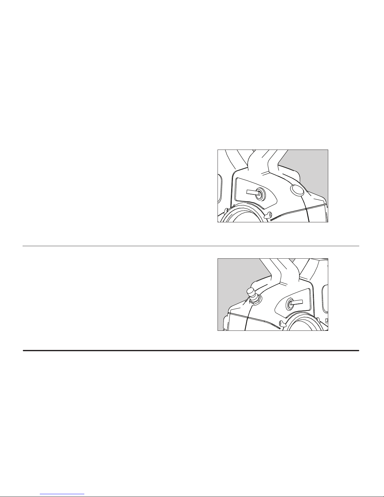
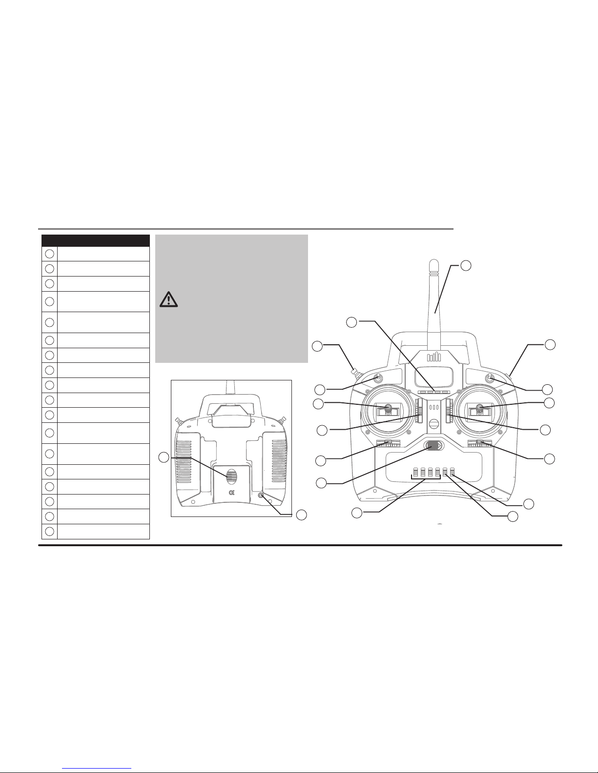
Anti-Crash Technology (ACT)
You can power ACT on and off during flight. When you gain flying experience,
power off ACT for full control.
On your DX4e transmitter, Power on and off ACT by moving the transmitter’s
switch between the on and off positions.
ACT is installed on your Super Cub LP to help prevent crashes due to over-control.
Sensors detect the horizon and direct the ight of the model. One sensor is at the
top of the windshield and the other is the bottom of the fuselage, in front of the
landing gear (see illustration). ACT uses information from the sensors to pull the
model out of steep dives and spirals. ACT keeps control of a model until the model
is in straight and level ight. The pilot must decrease throttle and release other
control sticks to neutral to get control from ACT. When ACT is powered on, and the
model dives, throttle is decreased (slowing the model to decrease risk of a crash)
and the elevator is moved to pull the nose up and out of a dive. Fly with ACT using
these guidelines:
• Keep ight control sticks in the middle and away from the ends of stick movement. Fly smoothly to prevent ACT from engaging. Move the control sticks in
small amounts. Transmitter control is proportional and the model is sensitive
to any movement of controls.
• ACT functions best when the aircraft is ying over 200 feet (61 meters).
• Fly your model to prevent a dive or other loss of control. When the model’s
nose falls, decrease the throttle and release the aileron (assigned to rudder
control) and elevator sticks. Add a small amount of UP elevator (pull back a
small amount on the elevator stick) to get control of the model.
• The ACT sensors detect light. ACT may take control when ying in snow
conditions, over water, over light-colored terrain or when the sun is near the
horizon. Avoid these ying conditions.
• Never y in an area where obstacles block ight. ACT cannot prevent collisions
with obstacles.
• Get help on your rst ights from an experienced pilot who has mastered a
3-channel radio system.
• Make several successful ights (including several soft landings) before ying
with ACT OFF.
With ACT Without ACT
Page 18

18
HobbyZone Super Cub • Instruction Manual
Flying
1. After you get your model off the ground, climb at full throttle. Your model’s
wing design causes a climb at full throttle without use of the elevator.
2. Adjust the throttle and rudder sticks to keep the model pointed into the wind.
Do not turn the model until the model is between 50 and 100 feet (15.25–
30.5 meters) above the ground, approximately the height of a 4-story building.
3. Keep your model in sight to maintain control. If you cannot see your model,
you cannot control it safely.
4. Do not let wind carry your model away from you. Keep the model upwind of
you. Fly carefully and pay attention to the wind pushing on your model. Wind is
stronger where your model ies. When ying high, move the throttle to the half
position (50%). Half throttle conserves battery power and results in smoother
and easier ying.
5. When off the ground, move the elevator stick smoothly in small amounts.
Small moves of the elevator stick make the model rise or fall.
6. Fly in large circles (see illustration) high off the ground to learn how to pilot the
model with the nose pointed toward you. Flying with the nose pointed toward
you is one of the hardest things to do when learning to y.
7. You can turn the model more sharply by moving the rudder in the direction you
want to turn and pulling the elevator stick back to you a small amount. When
ying at half (50%) or lower throttle, more space is needed for turns.
8. Do not put the model into long vertical dives, with the motor on or off. Dives
can damage the model and may result in a high-speed crash.
9. Pay attention to how long your model is in the air so the model is not high in
the air when the battery fully discharges. Land your model when more throttle
is required to maintain altitude.
Rudder trim: When the model drifts left or right at the same time the aileron stick
(used to control the rudder) is at neutral (centered) position, adjust control stick
trim a small amount OPPOSITE the direction of drift. Adjust trim so the model ies
straight at the same time the control stick is at neutral.
Elevator trim: When the model’s nose drifts up or down at the same time the
elevator stick is at neutral (centered) position, move the elevator trim lever (left of
the elevator stick) a small amount OPPOSITE the direction of drift. Adjust trim so
the model ies straight and level at the same time the elevator stick is at neutral.
Your Super Cub climbs steadily at full throttle when trimmed correctly.
NOTICE: A servo will make a noise when it is under too much load, sometimes
caused by the servo being trimmed too far in one direction. When a servo makes
noise, quickly adjust transmitter trim to neutral, and make sure servo correctly
operates when the transmitter control is moved.
LVC
When a Li-Po battery is discharged below 3V per cell, it will not hold a charge.
The ESC protects the ight battery from over-discharge using Low Voltage Cutoff
(LVC). Before the battery charge decreases too much, LVC removes power supply
from the motor. Power to the motor will be stopped, indicating that the battery is
discharged and that it is time to land.
When the motor shuts off, land the aircraft immediately and recharge the ight
battery. It is possible to lower the throttle stick and re-arm the speed control if a
small amount of power is needed for landing. Disconnect and remove the Li-Po
battery from the aircraft after use to prevent trickle discharge. Fully charge your
Li-Po battery before storing it. During storage make sure battery charge does not
go below 3V per cell.
Page 19

19
HobbyZone Super Cub • Instruction Manual
Landing
1. The Super Cub ies for approximately 10–12 minutes on one battery charge.
When the model climbs slower at full throttle, land the model and recharge
the battery.
2. Decrease the throttle and bring the model down to landing by pointing the
model’s nose into the wind, aligned with the length of your chosen runway.
3. When the model is approximately 10–15 feet (3–4.5 meters) above the
ground, slowly decrease the throttle until the throttle is fully off.
4. Carefully glide your model into landing, using little or no moves of the elevators
and rudder.
5. Use only very small amounts of throttle as needed to maintain control.
6. Fully decrease the throttle at landing to prevent damage to the wing and
propeller.
NOTE: When ying skills are developed, use a little UP elevator (pulling the elevator stick back) to “are” the model. Using are at landing can bring the model
down smoothly in a small landing area.
WARNING: Do not catch the ying model in your hands; personal injury
and/or damage to the model can result.
Repairing Minor Damage
When there is minor damage from a crash:
• Use packing tape to cover small holes.
• Repair foam parts with foam-compatible CA.
• Replace a bent or broken wing, fuselage and tail before ying again.
• Buy replacement parts using Replacement Parts list at the back of this
manual.
Reduce power
at 10 feet
Page 20

20
HobbyZone Super Cub • Instruction Manual
Throttle Adjustment
1. Fully increase throttle (100%) to launch your model.
2. Increase the throttle above half (50%) to make the model go up.
Note: Increased wind speeds can both increase lift from the wing and
increase difculty in turning the model.
3. When the model is above the ground where you want to y, decrease throttle
to half for cruising. Half throttle lets you y the model longer than when ying
the model at full throttle.
4. Decrease the throttle below half to bring the model down.
50%
50%
50%
Aerobatic Flight
An experienced pilot can safely make the Super Cub perform aerobatic maneuvers (loops and stalls). The steps below describe adjusting the model for these
aerobatic maneuvers.
1. Make sure ACT is OFF.
2. Remove the clevises from the outermost holes in the control horns.
3. Install the clevises in the innermost holes of the control horns.
Note: Changing the installation point of the clevises increases the control
throw (or range of motion) of the control surfaces. This makes the model
more sensitive to movement of the aileron (assigned to rudder control) and
elevator stick, so the model can stall more easily.
4. After moving a clevis, do a Control Test, center the control surface and adjust
trim.
Note: Crash damage is not covered under warranty.
Page 21

21
HobbyZone Super Cub • Instruction Manual
Disassembly
1. Remove spinner A from propeller B and hex nut
(spinner is tight on hex nut).
2. Remove hex nut, washer and propeller from gear shaft F.
3. Remove 3 screws and cowl C from fuselage.
4. Remove 4 screws, 4 washers and gearbox E from rewall G.
5. In the fuselage, disconnect 2 bullet connectors of motor D from ESC
connectors (motor wire colors align with ESC wire colors) and remove motor
wires from fuselage.
6. Disconnect Receiver/ESC unit and remove unit from retainer in fuselage.
7. Remove hex nut, washer, spacer and front bearing from gear shaft.
8. Remove gear shaft and rear bearing from gearbox.
9. Remove 2 screws, 2 rubber washers and motor D from gearbox.
Assembly
10. Assemble model by obeying instructions above in reverse.
11. Make sure propeller size numbers (9 X 6) face forward. The propeller ts on
hex nut on gear shaft.
12. Make sure gear on gear shaft and pinion gear on motor correctly align.
13. Make sure wires are not pinched or damaged when model is assembled.
14. Use clear tape to hold receiver antennas in fuselage so 2 antennas are kept
at right angles to each other for correct receiver operation.
Note: Threadlock may be required on the 2 screws holding motor in gearbox to
prevent loosening from vibration.
CAUTION: DO NOT handle the spinner, propeller, motor or Receiver/ESC
unit while the battery is connected to the Receiver/ESC. Personal injury
could result.
Service of Power Components
M1.5X6
M2.5X6
M2X25
G
F
E
D
C
B
A
Page 22
22
HobbyZone Super Cub • Instruction Manual
Problem Possible Cause Solution
Transmitter does not operate
model.
Low charge in transmitter batteries Replace transmitter batteries with fully charged batteries
No electrical connection Make sure ight battery is connected in model
Low charge in ight battery Replace ight battery with fully charged battery
Receiver or antenna damaged Repair or replace receiver
Receiver not bound to transmitter Bind receiver to transmitter
Model keeps turning in one
direction.
Rudder trim or rudder is not adjusted correctly Adjust rudder trim on transmitter or adjust model rudder
Wing is not centered on the fuselage Center wing and tighten wing connections to fuselage
Model is difcult to control.
Wind is too great for safe ying Postpone ying until the wind becomes calm
Damage to model Repair or replace damaged parts (propeller, wing, servos, etc)
Low charge in transmitter batteries or ight battery Replace batteries with fully charged batteries
Model keeps pitching up (nose
points up) steeply.
Wind is too great for safe ying Postpone ying until the wind becomes calm
Elevator is trimmed UP too much Decrease UP trim of elevator on transmitter
Motor speed increases and
decreases.
ACT is powered ON Power OFF the ACT
ACT is ON, but light is reecting on sensors Power OFF the ACT or y under other conditions (not snow, sand, etc)
ACT is ON and sun is low on horizon Power OFF the ACT or postpone using ACT until sun is higher in the sky
LVC from low charge in ight battery Replace ight battery with fully charged battery
Model will not climb as needed.
Low charge in ight battery Replace ight battery with fully charged battery
Elevator trimmed DOWN too much Decrease DOWN trim of elevator on transmitter
Propeller installed backwards Install propeller with numbers facing forward
Damage to model Repair or replace damaged parts (propeller, wing, etc)
Wind is too great for safe ying Postpone ying until the wind becomes calm
Flight conditions may be too cold Make sure battery is warm before use
Troubleshooting Guide
Page 23

23
HobbyZone Super Cub • Instruction Manual
Problem Possible Cause Solution
Aircraft will not respond to throttle
but responds to other controls
Throttle not at idle and/or throttle trim too high Reset controls with throttle stick and throttle trim at lowest setting
Throttle channel is reversed Reverse throttle channel on transmitter
Extra propeller noise or extra
vibration
Damaged propeller and spinner, gear shaft or motor Replace damaged parts
Propeller is out of balance Balance or replace propeller
Reduced ight time or aircraft
underpowered
Flight battery charge is low Completely recharge ight battery
Propeller installed backwards Install propeller with numbers facing forward
Flight battery damaged Replace ight battery and follow ight battery instructions
Flight conditions may be too cold Make sure battery is warm before use
Battery capacity may be low for ight conditions Replace battery or use a larger capacity battery
Aircraft will not link to transmitter Transmitter too near aircraft during binding process Move powered transmitter a few feet from aircraft,
disconnect and reconnect ight battery to aircraft
Aircraft not bound to transmitter Bind transmitter to aircraft receiver
Aircraft bound to different model memory
(ModelMatch radios only)
Select correct model memory on transmitter
Flight battery/Transmitter battery charge is too low Replace/recharge batteries
Control surface does not move Control surface, control horn, linkage or servo damage Replace or repair damaged parts and adjust controls
Wire damaged or connections loose Do a check of wires and connections, connect
or replace as needed
Transmitter not bound correctly Bind transmitter to aircraft receiver
Control trim out of adjustment Adjust trims to restore full control
Controls reversed Transmitter settings reversed Do the Control Direction Test and adjust controls on transmitter appropriately
Motor loses power Damage to motor, propeller shaft or power components Do a check of batteries, transmitter, receiver, motor and wiring for damage
(replace as needed)
Motor power pulses then motor
loses power
ESC uses default LVC Recharge ight battery or replace battery
that is no longer performing
Troubleshooting Guide, continued
Page 24

24
HobbyZone Super Cub • Instruction Manual
Replacement Parts
Number Description
HBZ1002 9 x 6 Propeller
HBZ1003 DC LiPo Balancing Charger
HBZ1004 1.5A AC Power Supply
HBZ7357 DSM2 Receiver/ESC unit
PKZ1033 1300mAh 11.1V Li-Po Battery with EC3 Connector
HBZ7104 Prop Shaft
HBZ7106 Landing Gear with Tires
HBZ7107 Spinner
HBZ7112 Battery Door with Latch
HBZ7114 Firewall with Screws
HBZ7117 Tail Wheel
HBZ7120 Standard Wing with Struts
HBZ7121 Control Horns (4)
HBZ7122 Wing Struts with Screws
HBZ7124 2 Wing Hold Down Rods
HBZ7125 Tail with Accessories
HBZ7126 Cowl
HBZ7127 White Rubber Bands
HBZ7128 Pushrods and Clevis Set
HBZ7129 Gearbox with Firewall
HBZ7134 Motor with Pinion
PKZ1536 Motor Screws (2): M 2.5 x 6
HBZ7135 Metal Pinion (2)
Number Description
HBZ7185 Bare Fuselage (no receiver)
HBZ7310 Decal Sheet: Super Cub LP
PKZ1130 Mini Servo (5W) with Arms
PKZ1131 Servo Gear Set
PKZ1132 Servo Arm Set
SPMR4400 DX4e 4-Channel Full Range Transmitter Only (Mode 2)
SPMR4401 DX4e 4-Channel Full Range Transmitter Only (Mode 1)
Optional Parts
Number Description
HBZ4020 Sonic Combat Module
HBZ3510 Aerial Drop Module
HBZ7390 Super Cub LP Floats
PKZ1005 10 x 8 High Power Propeller (for use with optional oats)
EFLAEC312 EC3 Charge Lead w/12” Wire & Jacks,16AWG
SPMR5500 DX5e 5-Channel Full Range Transmitter Only (Mode 2)
SPMR5501 DX5e 5-Channel Full Range Transmitter Only (Mode 1)
SPMR6600 DX6i 6-Channel Full Range Transmitter Only (Mode 2)
SPMR6601 DX6i 6-Channel Full Range Transmitter Only (Mode 1)
SPMR8800 DX8 8-Channel Full Range Transmitter Only (Mode 2)
SPMR8801 DX8 8-Channel Full Range Transmitter Only (Mode 1)
RTM25R5500 Phoenix R/C Pro Flight Simulator 2.5 with DX5e
RTM2500 Phoenix R/C Pro Flight Simulator 2.5
Page 25

25
HobbyZone Super Cub • Instruction Manual
AMA National Model Aircraft Safety Code
Effective January 1, 2011
A. GENERAL: A model aircraft is a non-human-carrying aircraft capable of sustained ight in
the atmosphere. It may not exceed limitations of this code and is intended exclusively for
sport, recreation and/or competition. All model ights must be conducted in accordance
with this safety code and any additional rules specic to the ying site.
1. Model aircraft will not be own:
(a) In a careless or reckless manner.
(b) At a location where model aircraft activities are prohibited.
2. Model aircraft pilots will:
(a) Yield the right of way to all man carrying aircraft.
(b) See and avoid all aircraft and a spotter must be used when appropriate. (AMA
Document #540-D-See and Avoid Guidance.)
(c) Not y higher than approximately 400 feet above ground level within three (3)
miles of an airport, without notifying the airport operator.
(d) Not interfere with operations and trafc patterns at any airport, heliport or sea-
plane base except where there is a mixed use agreement.
(e) Not exceed a takeoff weight, including fuel, of 55 pounds unless in compliance
with the AMA Large Model Aircraft program. (AMA Document 520-A)
(f) Ensure the aircraft is identied with the name and address or AMA number of the
owner on the inside or afxed to the outside of the model aircraft. (This does not
apply to model aircraft own indoors).
(g) Not operate aircraft with metal-blade propellers or with gaseous boosts except for
helicopters operated under the provisions of AMA Document #555.
(h) Not operate model aircraft while under the inuence of alcohol or while using any
drug which could adversely affect the pilot’s ability to safely control the model.
(i) Not operate model aircraft carrying pyrotechnic devices which explode or burn, or
any device which propels a projectile or drops any object that creates a hazard to
persons or property.
Exceptions:
• Free Flight fuses or devices that burn producing smoke and are securely
attached to the model aircraft during ight.
• Rocket motors (using solid propellant) up to a G-series size may be used
provided they remain attached to the model during ight. Model rockets
may be own in accordance with the National Model Rocketry Safety Code
but may not be launched from model aircraft.
• Ofcially designated AMA Air Show Teams (AST) are authorized to use
devices and practices as dened within the Team AMA Program Document
(AMA Document #718).
(j) Not operate a turbine-powered aircraft, unless in compliance with the AMA
turbine regulations. (AMA Document #510-A).
3. Model aircraft will not be own in AMA sanctioned events, air shows or model demonstrations unless:
(a) The aircraft, control system and pilot skills have successfully demonstrated all
maneuvers intended or anticipated prior to the specic event.
(b) An inexperienced pilot is assisted by an experienced pilot.
4. When and where required by rule, helmets must be properly worn and fastened. They
must be OSHA, DOT, ANSI, SNELL or NOCSAE approved or comply with comparable
standards.
B. RADIO CONTROL (RC)
1. All pilots shall avoid ying directly over unprotected people, vessels, vehicles or structures and shall avoid endangerment of life and property of others.
2. A successful radio equipment ground-range check in accordance with manufacturer’s
recommendations will be completed before the rst ight of a new or repaired model
aircraft.
3. At all ying sites a safety line(s) must be established in front of which all ying takes
place (AMA Document #706-Recommended Field Layout):
(a) Only personnel associated with ying the model aircraft are allowed at or in front
of the safety line.
(b) At air shows or demonstrations, a straight safety line must be established.
(c) An area away from the safety line must be maintained for spectators.
(d) Intentional ying behind the safety line is prohibited.
4. RC model aircraft must use the radio-control frequencies currently allowed by the
Federal Communications Commission (FCC). Only individuals properly licensed by the
FCC are authorized to operate equipment on Amateur Band frequencies.
5. RC model aircraft will not operate within three (3) miles of any pre-existing ying site
without a frequency-management agreement (AMA Documents #922- Testing for RF
Interference; #923- Frequency Management Agreement)
6. With the exception of events own under ofcial AMA Competition Regulations,
excluding takeoff and landing, no powered model may be own outdoors closer than
25 feet to any individual, except for the pilot and the pilot’s helper(s) located at the
ight line.
7. Under no circumstances may a pilot or other person touch a model aircraft in ight
while it is still under power, except to divert it from striking an individual. This does not
apply to model aircraft own indoors.
8. RC night ying requires a lighting system providing the pilot with a clear view of the
model’s attitude and orientation at all times.
9. The pilot of a RC model aircraft shall:
(a) Maintain control during the entire ight, maintaining visual contact without
enhancement other than by corrective lenses prescribed for the pilot.
(b) Fly using the assistance of a camera or First-Person View (FPV) only in accor-
dance with the procedures outlined in AMA Document #550.
Page 26

26
HobbyZone Super Cub • Instruction Manual
Warranty and Repair Policy
Warranty Period
Exclusive Warranty- Horizon Hobby, Inc., (Horizon) warranties that the Products purchased
(the “Product”) will be free from defects in materials and workmanship at the date of purchase by the Purchaser.
Limited Warranty
Horizon reserves the right to change or modify this warranty without notice and
disclaims all other warranties, express or implied.
This warranty is limited to the original Purchaser (“Purchaser”) and is not transferable. REPAIR OR REPLACEMENT AS PROVIDED UNDER THIS WARRANTY IS THE EXCLUSIVE REMEDY
OF THE PURCHASER. This warranty covers only those Products purchased from an authorized
Horizon dealer. Third party transactions are not covered by this warranty. Proof of purchase is
required for all warranty claims.
(b) Limitations- HORIZON MAKES NO WARRANTY OR REPRESENTATION, EXPRESS OR
IMPLIED, ABOUT NON-INFRINGEMENT, MERCHANTABILITY OR FITNESS FOR A PARTICULAR
PURPOSE OF THE PRODUCT. THE PURCHASER ACKNOWLEDGES THAT THEY ALONE HAVE
DETERMINED THAT THE PRODUCT WILL SUITABLY MEET THE REQUIREMENTS OF THE
PURCHASER’S INTENDED USE.
(c) Purchaser Remedy- Horizon’s sole obligation hereunder shall be that Horizon will, at its
option, (i) repair or (ii) replace, any Product determined by Horizon to be defective. In the
event of a defect, these are the Purchaser’s exclusive remedies. Horizon reserves the right to
inspect any and all equipment involved in a warranty claim. Repair or replacement decisions
are at the sole discretion of Horizon. This warranty does not cover cosmetic damage or damage due to acts of God, accident, misuse, abuse, negligence, commercial use, or modication
of or to any part of the Product. This warranty does not cover damage due to improper installation, operation, maintenance, or attempted repair by anyone other than Horizon. Return of
any Product by Purchaser must be approved in writing by Horizon before shipment.
Damage Limits
HORIZON SHALL NOT BE LIABLE FOR SPECIAL, INDIRECT OR CONSEQUENTIAL DAMAGES,
LOSS OF PROFITS OR PRODUCTION OR COMMERCIAL LOSS IN ANY WAY CONNECTED WITH
THE PRODUCT, WHETHER SUCH CLAIM IS BASED IN CONTRACT, WARRANTY, NEGLIGENCE,
OR STRICT LIABILITY. Further, in no event shall the liability of Horizon exceed the individual
price of the Product on which liability is asserted. As Horizon has no control over use, setup,
nal assembly, modication or misuse, no liability shall be assumed nor accepted for any
resulting damage or injury. By the act of use, setup or assembly, the user accepts all resulting
liability.
If you as the Purchaser or user are not prepared to accept the liability associated with the
use of this Product, you are advised to return this Product immediately in new and unused
condition to the place of purchase.
Law: These Terms are governed by Illinois law (without regard to conict of law principals).
Warranty Services
Questions, Assistance, and Repairs
Your local hobby store and/or place of purchase cannot provide warranty support or repair.
Once assembly, setup or use of the Product has been started, you must contact Horizon
directly. This will enable Horizon to better answer your questions and service you in the event
that you may need any assistance. For questions or assistance, please direct your email to
productsupport@horizonhobby.com, or call 877.504.0233 toll free to speak to a Product
Support representative. You may also nd information on our website at www.horizonhobby.
com.
Inspection or Repairs
If this Product needs to be inspected or repaired, please use the Horizon Online Repair Request submission process found on our website or call Horizon to obtain a Return Merchandise Authorization (RMA) number. Pack the Product securely using a shipping carton. Please
Note that original boxes may be included, but are not designed to withstand the rigors of
shipping without additional protection. Ship via a carrier that provides tracking and insurance
for lost or damaged parcels, as Horizon is not responsible for merchandise until it arrives and
is accepted at our facility. An Online Repair Request is available at www.horizonhobby.com
under the Repairs tab. If you do not have internet access, please contact Horizon Product
Support to obtain a RMA number along with instructions for submitting your product for repair. When calling Horizon, you will be asked to provide your complete name, street address,
email address and phone number where you can be reached during business hours. When
sending product into Horizon, please include your RMA number, a list of the included items,
and a brief summary of the problem. A copy of your original sales receipt must be included
for warranty consideration. Be sure your name, address, and RMA number are clearly written
on the outside of the shipping carton.
Notice: Do not ship batteries to Horizon. If you have any issue with a battery,
please contact the appropriate Horizon Product Support office.
Warranty Inspection and Repairs
To receive warranty service, you must include your original sales receipt verifying
the proof-of-purchase date. Provided warranty conditions have been met, your Product
will be repaired or replaced free of charge. Repair or replacement decisions are at the sole
discretion of Horizon.
Non-Warranty Repairs
Should your repair not be covered by warranty the repair will be completed and
payment will be required without notification or estimate of the expense unless
the expense exceeds 50% of the retail purchase cost. By submitting the item for repair
you are agreeing to payment of the repair without notication. Repair estimates are available
upon request. You must include this request with your repair. Non-warranty repair estimates
will be billed a minimum of ½ hour of labor. In addition you will be billed for return freight.
Horizon accepts money orders and cashiers checks, as well as Visa, MasterCard, American
Express, and Discover cards. By submitting any item to Horizon for inspection or repair, you
are agreeing to Horizon’s Terms and Conditions found on our website under the Repairs tab.
Page 27

27
HobbyZone Super Cub • Instruction Manual
Warranty and Service Contact Information
Parts Contact Information
Country of
Purchase
Horizon Hobby Address
Phone Number /
Email Address
United States Sales
4105 Fieldstone Rd
Champaign, Illinois, 61822
USA
800-338-4639
sales@horizonhobby.com
United
Kingdom
Horizon Hobby Limited
Units 1-4 Ployters Rd
Staple Tye
Harlow, Essex
CM18 7NS, United Kingdom
+44 (0) 1279 641 097
sales@horizonhobby.co.uk
Germany Horizon Hobby GmbH
Hamburger Str. 10
25335 Elmshorn, Germany
+49 4121 46199 60
service@horizonhobby.de
France Horizon Hobby SAS
14 Rue Gustave Eiffel
Zone d’Activité du Réveil
Matin
91230 Montgeron
+33 (0) 1 60 47 44 70
infofrance@horizonhobby.
com
Country of
Purchase
Horizon Hobby Address
Phone Number /
Email Address
United States
of America
Horizon Service Center
(Electronics and engines)
4105 Fieldstone Rd
Champaign, Illinois, 61822
USA
877-504-0233
Online Repair Request:
visit www.horizonhobby.
com/repairs
Horizon Product Support
(All other products)
4105 Fieldstone Rd
Champaign, Illinois, 61822
USA
877-504-0233
productsupport@horizonhobby.com
United
Kingdom
Horizon Hobby Limited
Units 1-4 Ployters Rd
Staple Tye
Harlow, Essex
CM18 7NS, United Kingdom
+44 (0) 1279 641 097
sales@horizonhobby.co.uk
Germany
Horizon Technischer
Service
Hamburger Str. 10
25335 Elmshorn, Germany
+49 4121 46199 66
service@horizonhobby.de
France Horizon Hobby SAS
14 Rue Gustave Eiffel
Zone d’Activité du Réveil
Matin
91230 Montgeron
+33 (0) 1 60 47 44 70
infofrance@horizonhobby.
com
FCC Information
This device complies with part 15 of the FCC rules. Operation is subject to
the following two conditions: (1) This device may not cause harmful interference, and (2) this device must accept any interference received, including
interference that may cause undesired operation.
CAUTION: Changes or modications not expressly approved by
the party responsible for compliance could void the user’s authority
to operate the equipment.
This product contains a radio transmitter with wireless technology which
has been tested and found to be compliant with the applicable regulations
governing a radio transmitter in the 2.400GHz to 2.4835GHz frequency
range.
Antenna Separation Distance
When operating your Spektrum transmitter, please be
sure to maintain a separation distance of at least 5 cm
between your body (excluding ngers, hands, wrists,
ankles and feet) and the antenna to meet RF exposure
safety requirements as determined by FCC regulations.
These illustrations show the approximate 5 cm RF
exposure area and typical hand placement when operating your Spektrum transmitter.
Page 28

28
HobbyZone Super Cub • Instruction Manual
(in accordance with ISO/IEC 17050-1)
No. HH2011031502
Product(s): HBZ Super Cub DSM RTF
Item Number(s): HBZ7400EU, HBZ7400EUM1,
HBZ7400UK, HBZ7400UK1
Equipment class: 2
The object of declaration described above is in conformity with the requirements of the
specications listed below, following the provisions of the European R&TTE directive
1999/5/EC and EMC Directive 2004/108/EC
EN 300-328 V1.7.1
EN 301 489-1 V1.7.1: 2006
EN 301 489-17 V1.3.2: 2008
EN 60950-1:2006+A11
EN55022: 2006,
EN55024: 1998+A1: 2001+A2: 2003
(EN61000-4-2: 2001, EN61000-4-3: 2006, EN61000-4-8: 2001)
Signed for and on behalf of:
Horizon Hobby, Inc.
Champaign, IL USA
Mar 15, 2011
Compliance Information for the European Union
Declaration of Conformity
Instructions for disposal of WEEE by users in the European Union
This product must not be disposed of with other waste. Instead, it is the
user’s responsibility to dispose of their waste equipment by handing it over
to a designated collections point for the recycling of waste electrical and
electronic equipment. The separate collection and recycling of your waste
equipment at the time of disposal will help to conserve natural resources
and ensure that it is recycled in a manner that protects human health and
the environment. For more information about where you can drop off your
waste equipment for recycling, please contact your local city ofce, your
household waste disposal service or where you purchased the product.
Steven A. Hall
Vice President
International Operations and Risk Management
Horizon Hobby, Inc.
AT BG CZ CY DE
DK ES FI FR GR
HU IE IT L T LU
LV MT NL PL PT
RO SE SI SK UK
Page 29

108
HobbyZone Super Cub • Manuale di istruzioni
©2011 Horizon Hobby, Inc.
US 7,515,070; PRC ZL 200510028326.6; US 7,391,320
Other patents pending.
HBZ7300 31209 Printed 2/11
 Loading...