

Page 1
Carbon Cub S2
Instruction Manual • Bedienungsanleitung • Manuel d’utilisation • Manuale di Istruzioni
Page 2
EN
All instructions, warranties and other collateral documents are subject to change at the sole discretion of Horizon Hobby, LLC. For up-to-date product literature,
visit horizonhobby.com or towerhobbies.com and click on the support or resources tab for this product.
The following terms are used throughout the product literature to indicate various levels of potential harm when operating this product:
WARNING: Procedures, which if not properly followed, create the probability of property damage, collateral damage, and serious injury OR create a high prob-
ability of supercial injury.
CAUTION: Procedures, which if not properly followed, create the probability of physical property damage AND a possibility of serious injury.
NOTICE: Procedures, which if not properly followed, create a possibility of physical property damage AND little or no possibility of injury.
WARNING: Read the ENTIRE instruction manual to become familiar with the features of the product before operating. Failure to operate the product
correctly can result in damage to the product, personal property and cause serious injury.
This is a sophisticated hobby product. It must be operated with caution and common sense and requires some basic mechanical ability. Failure to operate this
Product in a safe and responsible manner could result in injury or damage to the product or other property. This product is not intended for use by children
without direct adult supervision. Do not use with incompatible components or alter this product in any way outside of the instructions provided by Horizon
Hobby, LLC. This manual contains instructions for safety, operation and maintenance. It is essential to read and follow all the instructions and warnings in the
manual, prior to assembly, setup or use, in order to operate correctly and avoid damage or serious injury.
WARNING AGAINST COUNTERFEIT PRODUCTS: If you ever need to replace your Spektrum receiver found
in a Horizon Hobby product, always purchase from Horizon Hobby, LLC or a Horizon Hobby authorized dealer
to ensure authentic high-quality Spektrum product. Horizon Hobby, LLC disclaims all support and warranty with
regards, but not limited to, compatibility and performance of counterfeit products or products claiming compatibility
with DSM or Spektrum technology.
14
AGE RECOMMENDATION:
Not for children under 14
+
years. This is not a toy.
Carbon Cub S2
NOTICE
Meaning of Special Language:
Safety Precautions and Warnings
As the user of this product, you are solely responsible for operating in a manner
that does not endanger yourself and others or result in damage to the product
or the property of others.
• Always keep a safe distance in all directions around your model to avoid
collisions or injury. This model is controlled by a radio signal subject to
interference from many sources outside your control. Interference can cause
momentary loss of control.
• Always operate your model in open spaces away from full-size vehicles, trafc and people.
• Always carefully follow the directions and warnings for this and any optional
support equipment (chargers, rechargeable battery packs, etc.).
• Always keep all chemicals, small parts and anything electrical out of the
reach of children.
• Always avoid water exposure to all equipment not specically designed and
protected for this purpose. Moisture causes damage to electronics.
• Never place any portion of the model in your mouth as it could cause serious
injury or even death.
• Never operate your model with low transmitter batteries.
• Always keep aircraft in sight and under control.
• Always use fully charged batteries.
• Always keep transmitter powered on while aircraft is powered.
• Always remove batteries before disassembly.
• Always keep moving parts clean.
• Always keep parts dry.
• Always let parts cool after use before touching.
• Always remove batteries after use.
• Always ensure failsafe is properly set before ying.
• Never operate aircraft with damaged wiring.
• Never touch moving parts.
Charging Warnings
CAUTION: All instructions and warnings must be followed exactly.
Mishandling of Li-Po batteries can result in a re, personal injury,
and/or property damage.
• NEVER LEAVE CHARGING BATTERIES UNATTENDED.
• NEVER CHARGE BATTERIES OVERNIGHT.
• By handling, charging or using the included Li-Po battery, you assume all
risks associated with lithium batteries.
• If at any time the battery begins to balloon or swell, discontinue use immediately.
If charging or discharging, discontinue and disconnect. Continuing to use, charge
or discharge a battery that is ballooning or swelling can result in re.
• Always store the battery at room temperature in a dry area for best results.
• Always transport or temporarily store the battery in a temperature range of
40–120º F (5–49º C). Do not store battery or aircraft in a car or direct sunlight. If stored in a hot car, the battery can be damaged or even catch re.
• Always charge batteries away from ammable materials.
®
• Always inspect the battery before charging and never charge dead or damaged batteries.
• Always disconnect the battery after charging, and let the charger cool
between charges.
• Always constantly monitor the temperature of the battery pack while charging.
• ONLY USE A CHARGER SPECIFICALLY DESIGNED TO CHARGE LI-PO BATTERIES. Failure to charge the battery with a compatible charger may cause re
resulting in personal injury and/or property damage.
• Never discharge Li-Po cells to below 3V under load.
• Never cover warning labels with hook and loop strips.
• Never charge batteries outside recommended levels.
• Never attempt to dismantle or alter the charger.
• Never allow minors under the age of 14 to charge battery packs.
• Never charge batteries in extremely hot or cold places (recommended between 40–120° F or 5–49° C) or place in direct sunlight.
2
Page 3
Carbon Cub S2
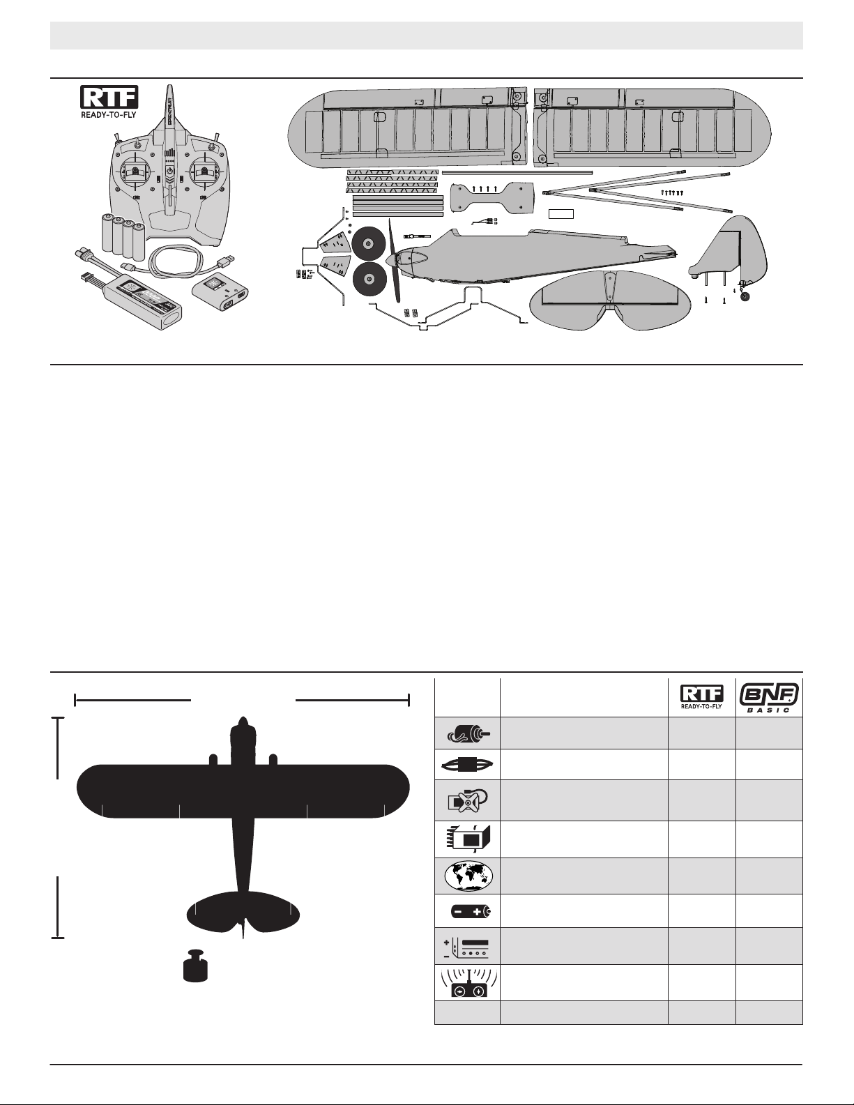
Box Contents
Table of Contents
Specications ................................................................................................. 3
Optional Upgrades .......................................................................................... 4
From the Box to the Air ................................................................................... 4
Charge the Flight Battery ................................................................................ 5
RTF Transmitter .............................................................................................. 6
BNF Transmitter Setup .................................................................................... 7
Hi/Low Rate Switch (Dual Rates) ..................................................................... 7
Transmitter and Receiver Binding .................................................................... 7
Assembly ........................................................................................................ 8
Factory Settings for the Control Horns and Servo Arms ................................. 11
Flight Control ................................................................................................ 11
Install the Flight Battery ................................................................................ 12
Center of Gravity (CG) ................................................................................... 12
Control Direction Test .................................................................................... 13
Range Test .................................................................................................... 14
Compass Calibration Procedure .................................................................... 15
Choose a Flying Field .................................................................................... 15
Install the Propeller ....................................................................................... 16
Trimming the Aircraft .................................................................................... 16
EN
Flying ........................................................................................................... 17
Landing ........................................................................................................ 19
Installing Optional Flaps ................................................................................ 20
PNP Receiver Selection and Installation ........................................................ 20
Flying With the Optional Float Set .................................................................. 21
Service and Repairs ...................................................................................... 22
Optional Landing Assist Sensor (LAS) Upgrade .............................................. 23
Optional SAFE+ GPS Upgrade ................................................................. 24–31
AS3X System Troubleshooting Guide ............................................................. 32
Troubleshooting Guide .................................................................................. 32
AMA National Model Aircraft Safety Code ...................................................... 33
Limited Warranty .......................................................................................... 34
Contact Information ...................................................................................... 35
FCC Information ............................................................................................ 35
IC Information ............................................................................................... 35
Compliance Information for the European Union ............................................ 35
Replacement Parts ...................................................................................... 133
Optional Parts ............................................................................................. 133
Specications
51 inch (1300mm)
34 inch (865mm)
2.3 lbs (1075 g)
For more information and to register your product online, visit www.hobbyzonerc.com
Motor: 480 Brushless Outrunner,
960Kv 14 Pole
ESC: 30A Installed Installed
Servos:
2 Aileron Servos, 1 Elevator Servo
and 1 Rudder Servo
Receiver: SPM4650C
Flight Controller: SPMA3232
GPS Module: SPMA3173 Optional Optional
Battery: 3S 2200mAh Li-Po
(SPMX22003S30)
Battery Charger: DC powered 3S
balancing fast charger (SPMXC1020)
Transmitter: Spektrum™ DXS
(SPMR1010)
LAS Unit (SPMA3180) Optional Optional
Installed Installed
Installed Installed
Installed Installed
Included
Included Optional
Included Optional
Required to
Complete
3
RTF/BNF Basic
Page 4

EN
Carbon Cub S2
Optional Upgrades (not included)
Landing Assist Sensor (LAS) GPS Module
When added, the LAS module will work hand-in-hand with the AutoLand
feature for a picture perfect landing every time. When the aircraft is on
approach and approximately 1m from the ground, the LAS module will level
out the aircraft, adjust throttle if needed, and then are the aircraft just
before touchdown.
When added, advanced SAFE+ features can keep the aircraft within a given
distance to the pilot (Virtual Fence), can return the model to home at the press of
a button (Holding Pattern), can return home automatically if the controller signal
is lost (Failsafe), and can land itself when commanded (AutoLand).
From the Box to the Air (No LAS or GPS Module)
1. Remove and inspect contents.
2. Read this instruction manual thoroughly.
3. Charge the ight battery.
4. Fully assemble the aircraft
5. Make sure all linkages move freely.
6. Install a fully charged ight battery in the aircraft.
7. Check the Center of Gravity (CG).
8. Set up your transmitter (BNF only)
9. Bind the aircraft to your transmitter (BNF only)
10. Place the aircraft into Experienced Mode (Mode switch position 2) for the Control Direction Test.
Place the aircraft on the ground facing away from you.
11. Perform the control direction test with the transmitter
12. Adjust the ight controls and transmitter as needed.
13. Place the aircraft into Beginner Mode (Mode switch position 0) for the SAFE Control Direction Test and takeoff.
14. Perform SAFE Control Direction Test
15. Find a safe open area to y.
16. Perform a radio system range test.
17. Plan ight for ying eld conditions.
18. Set ight time for 8 minutes.
®
4
Page 5

Charge the Flight Battery
Carbon Cub S2
EN
The recommended battery for the E-ite Carbon Club S2 aircraft, included
with the RTF version, is an 11.1V, 2200mAh 3S 30C Smart Technology
LiPo battery with an IC3™ connector (SPMX22003S30). If using a different
battery, the battery should be of similar capacity, dimensions and weight
to t in the fuselage. The aircraft electronic speed control is equipped with
an IC3 device connector. Ensure the battery chosen is compatible. Always
ensure the model balances at the recommended center of gravity (CG)
with the chosen battery. Follow your chosen battery and battery charger
instructions to charge the ight battery.
RTF Smart Technology Battery and S120 Charger,
Specications and Operation
The Spektrum S120 SMART Technology battery charger included with the
RTF version of the aircraft is compatible only with Spektrum SMART 2-3
cell LiPo batteries or 6-7 cell NiMH batteries. It is not compaptible with any
other battery chemistries or non-SMART batteries.
A USB power supply is required for use. A USB-C QC type power supply is
recommended for the fastest charge times.
S120 Specications
Input USB Type C, power supply not included
Input Voltage 5V-12V
Charge Power 18W max (dependant on power supply)
Compatible USB Power
Adaptor
Battery Connector IC3™ and balance connector
Battery Types LiPo, NiMH (Spektrum SMART Batteries only)
Cell Count 2-3 cell LiPo, 6-7 cell NiMH
Max Output Voltage 13.05V
Max Output Current Up to 2A
USB-C port LED Indicator
5V/1A, 5V/2A, USB Quick Charge (QC) 2.0/3.0
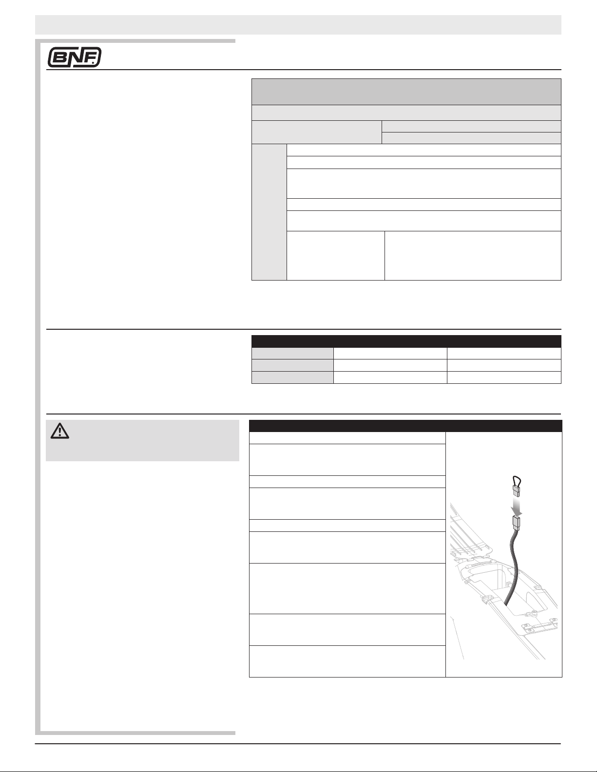
To charge the included ight battery:
1. Using the supplied Type-C USB cable, connect the S120 charger to a USB
power supply (not included ).
2. Insert the Spektrum
SMART Battery IC3
connector (A) into
the charger IC3 port,
and insert the battery
balance lead (B) into
the charger balance
port. Both the IC3 and
balance connectors
must be connected for
the charging process to begin. The battery may be disconnected from the
charger at any time to stop the charging process.
IMPORTANT: SMART NiMH batteries do not have a balance connector.
3. Disconnect the IC3 and balance connectors when the charge and balance
cycles are complete, as indicated by the LED.
4. The LED indicator will glow solid red to indicate a charging error. Follow
the operation steps to ensure proper connection is used to charge the
battery.
Refer to the LED indicator table for charger status.
IMPORTANT: Connecting a non-SMART battery will cause a charge error and
the S120 will not recognize or charge the battery.
A
B
IC3 Charge Port
Balance Port
LED Indicator
Power On
LiPo: Purple LED
NiMH: Yellow LED
Charge Complete Green LED (Solid)
Error Red LED (Solid)
USB 5V: White LED
USB Quick Charge 2.0/3.0: Blue LED
Battery Capacity
Less Than 25% Single Flash
25% – 75% Double Flash
76% – 99% Triple Flash
5
RTF/BNF Basic
Page 6
EN
A
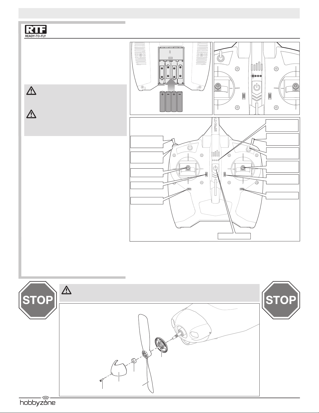
Transmitter
Installing the Transmitter Batteries
Remove the battery cover, install the four included batteries
(noting proper polarity) and reinstall the battery cover.
Low Battery Alarm
The LED indicator ashes and the transmitter beeps progressively faster as the battery voltage drops.Replace the
transmitter batteries when the transmitter begins to beep.
CAUTION: If using rechargeable batteries, charge
only rechargeable batteries. Charging nonrechargeable batteries may cause the batteries to burst,
resulting in injury to persons and/or damage to property.
WARNING: Do not pick up the transmitter by
the antenna. Do not alter or put weight on the
antenna. Damage to antenna parts can decrease transmitter signal strength, which can result in loss of model
control, injury or property damage.
For complete transmitter instructions and features, visit
horizonhobby.com.
Battery Voltage Level
The included DXS transmitter includes a new ight battery
voltage level indicator feature.
LED SMART Battery voltage indication is based on current
voltage and will change with throttle/power usage. When
throttle is increased, voltage drops, causing the bars to
indicate lower power (e.g., fewer LEDs solid or ashing.)
When the throttle is lowered to idle/off, the bars recover
(e.g., more LEDs solid or ashing). LED bars will rise and
lower depending on throttle/power usage.
The SMART Battery low voltage alarm sounds when the
ESCs are close to reaching low voltage cutoff. The alarm
will sound for 25 seconds. If the throttle is lowered to allow
voltage recovery, the alarm will stop early.
Land the aircraft when the alarm sounds.
After landing, reset the SMART Battery low voltage warning
by either (1) powering cycling the DXS transmitter, or (2)
disconnecting the battery from the aircraft for more than
15 seconds or until the LED voltage indication bars go out.
Connect a fully charged battery to the aircraft, which will
ensure the SMART Battery low voltage warning resets prior
to the next ight.
Carbon Cub S2
Mode 2 shown
SAFE Plus Mode
Switch
Bind/HP*/AL*
Button
Throttle/Rudder
Throttle Trim
Rudder Trim
*(HP)= Holding Pattern
*(AL) = AutoLand
Flight Battery
Voltage Indicator
Throttle Cut
Switch
Hi / Low Rate
Switch
Elevator/Aileron
Stick
Elevator Trim
Aileron Trim
Power Switch
WARNING: Before proceeding further, remove the propeller and spinner from the motor shaft. Never attempt to program the radio components, assemble the aircraft or perform maintenance of any kind without
removing the propeller. Serious injury could result if the motor starts inadvertently with the propeller still attached.
1. Remove the M2.5 X 8 mm screw (A)
and spinner (B).
2. Use an adjustable wrench to remove the
hex nut (C), propeller (D) and spinner
backplate (E).
E
C
B
®
D
6
Page 7
Transmitter Setup
Carbon Cub S2
EN
IMPORTANT: The included ight controller has been
programmed for operation specically in this aircraft. The
programming in this ight controller cannot be changed by
the user.
To operate the SAFE® or optional SAFE Plus system in this
aircraft, set up your optional DSM2®/DSMX® transmitter*
using the chart.
- SAFE Plus Flight modes are selected using Channel 5
signal (high, middle, low)
IMPORTANT: A transmitter with a 2-position Channel 5
switch will only allow the use of position 0 or position 2
ight modes. If possible (refer to your transmitter manual),
assign Channel 5 in your transmitter to a 3-position switch
to operate all 3 ight modes.
Refer to your transmitter manual for more information
about transmitter setup.
* The Carbon Cub S2 aircraft is not compatible with DX4e
or DX5e transmitters.
Hi/Low Rate Switch (Dual Rates)
The included DSMX® full range transmitter features dual
rates to allow you to select the amount of travel that you
want from the control surfaces.
Computerized Transmitter Setup
(DX6 Gen2, DX6e,DX7 Gen2, DX8 Gen2, DX9, DX18 and DX20)
Start all transmitter programming with a blank model (do a model reset), then name the model.
Set Aileron, Elevator, and Rudder Rates to:
1. Go to the SYSTEM SETUP
2. Set MODEL TYPE: AIRPLANE
3. Go to CHANNEL ASSIGN:
click NEXT to go to Channel Input Cong:
DX6
DX6e
DX8
DX9
DX18
DX20
Conrm AUX1 is not reversed. If AUX1 is reversed, the ESC and the GPS system will not arm,
indicated by full down elevator.
Aileron 100% 70%
Elevator 100% 70%
Rudder 100% 70%
GEAR: B, AUX1: I
4. Go to the FUNCTION LIST
5. Go to Throttle Cut:
set to Switch H, Position: –130
Resulting in:
Dual Rate High Rate Low Rate
HIGH 100%
LOW 70%
Switch H operates Throttle Cut, position 0 is normal
and position 1 cuts power to the throttle.
Switch B operates the 3 SAFE modes
(0 beginner/1 intermediate/2 experienced)
Button I operates PANIC mode when pressed
Transmitter and Receiver Binding
CAUTION: Connecting the battery to the ESC with
reversed polarity will cause damage to the ESC,
the battery or both. Damage caused by incorrectly connecting the battery is not covered under warranty.
IMPORTANT: The included ight controller has been
programmed for operation specically in this aircraft. The
programming in this ight controller cannot be changed by
the user.
An extension is installed in the ight controller bind port
so binding may be done through the battery door in the
bottom of the aircraft without having to remove the wing
assembly. Simply insert the bind plug in the open end of
the extension marked “bind” to enter bind mode.
The included RTF transmitter is bound to the aircraft at the
factory. If you need to re-bind for any reason, follow the
binding procedure as shown.
You need to ‘bind’ your chosen Spektrum™ DSM2®/DSMX®
technology equipped aircraft transmitter to the receiver for
proper operation. Please refer to the optional parts list in this
manual or visit www.bindny.com for a list of compatible
transmitters.
Refer to your transmitter instructions for binding to a receiver.
The throttle will not arm if the transmitter’s throttle stick is not
put at the lowest position and the throttle trim centered or lower.
If you encounter problems, follow the binding instructions
and refer to the transmitter troubleshooting guide for other
instructions. If needed, contact the appropriate Horizon
Product Support ofce.
Binding Procedure Reference Table
1. Make sure the transmitter is powered off.
2. Make sure the transmitter controls are neutral, the
throttle is at the lowest position*, the throttle trim is
centered and the aircraft is immobile.
3. Install a bind plug in the bind port extension.
4. Connect the ight battery to the ESC. The ESC will
produce a long tone followed by a series of additional
short tones.
5. The status LED will begin to ash rapidly.
6. Power on the transmitter while holding the transmitter bind button or switch. Refer to your transmitter’s
manual for specic binding instructions.
7. When the receiver binds to the transmitter, the orange
bind light on the receiver will turn solid and the ESC will
produce ascending tones. The tones indicate the ESC is
armed, provided the throttle stick and throttle trim are
low enough to trigger arming.
8. Remove the bind plug from the bind port. The receiver
should retain the binding instructions received from the
transmitter until another binding is done.
9. Safely store the bind plug (some owners attach the
bind plug to their transmitter using two-part loops and
clips).
* The throttle will not arm if the transmitter’s throttle stick is not put at the lowest position. The
aircraft will not arm when it is upside down.
7
RTF/BNF Basic
Page 8
EN
Carbon Cub S2
Applies only when the optional GPS module is installed
IMPORTANT: IF THE OPTIONAL GPS MODULE IS INSTALLED the aircraft will not respond to transmitter commands after binding if it cannot acquire a
GPS signal.
Binding: After binding with the GPS module installed, the aircraft will search for a GPS lock, indicated by the elevator slowly cycling up and down. After
acquiring a GPS lock, all ight controls will respond normally except throttle. The throttle will be limited, allowing the aircraft to be taxied out to takeoff
position on the runway. Set the home position to regain full functioning throttle. See the Powering On With GPS section of this manual for further details.
Compass calibration: After binding the rst time with the GPS module installed in the aircraft, compass calibration is required. The aircraft will automatically
enter the compass calibration sequence after installing the GPS for the rst time. This is indicated by the ailerons slowly cycling up and down. The aircraft will
not respond to transmitter commands with the GPS module installed until calibration has been completed. See the Compass Calibration section of this manual
for further details.
Subsequent binding with the GPS module will not require compass calibration.
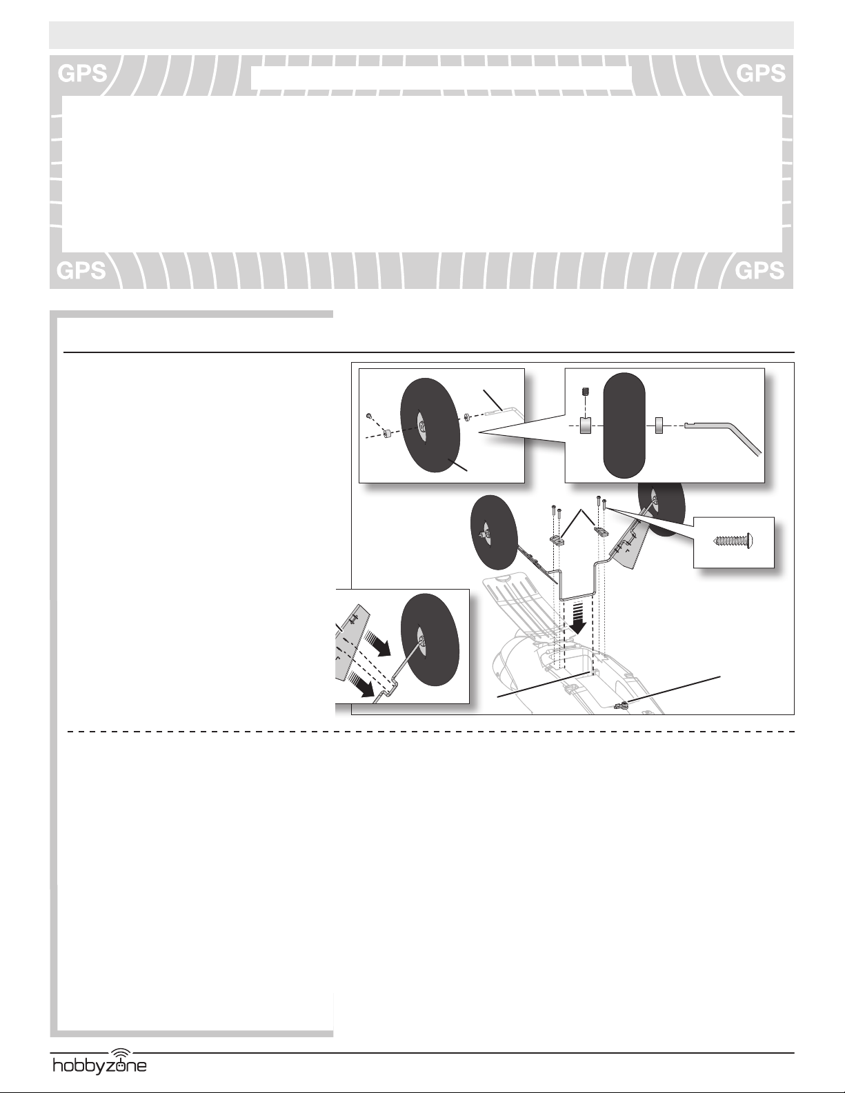
Assembly
Install the Main Landing Gear
1. Install 2 wheels (A) on the strut (B) using wheel collars and
spacers. Only the outer wheel collars require a set screw.
Tighten the set screws on the at spots of the strut.
TIP: Threadlock may be required to keep the collar on the strut.
2. Install the left and right fairings (E) (marked L and R) on
the respective sides of the strut.
3. Turn the latch (F) and open the battery hatch.
4. Install the strut in the channels (G) in the fuselage as shown.
5. Install the left and right strut brackets (H) (marked L and R)
in the respective slots on the bottom of the fuselage using
4 screws (I).
6. Replace the battery hatch and turn the latch.
Disassemble in reverse order.
B
A
H
I
2.5 X 10mm (4)
E
F
G
®
8
Page 9
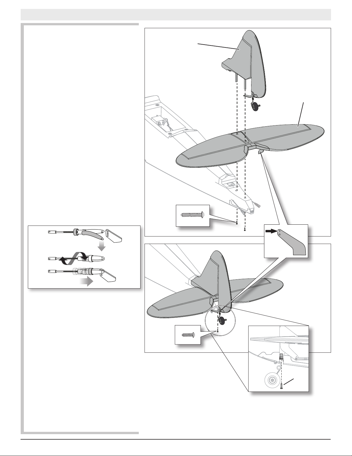
Install the Tail
1. Install the horizontal tail (A) on the fuselage as shown.
2. Carefully insert the 2 pins of the vertical n (B) through
the horizontal tail holes and the fuselage holes. Turn the
rudder so the control horn is under the horizontal tail.
3. Under the fuselage, install the 2 screws (C) into the
fuselage and the vertical n pins. Tighten the screws,
but do not break the plastic.
4. Install the rudder hinge screw (D) as shown. Tighten the
screw, then loosen it one half of a turn so the rudder
turns freely.
5. Connect the respective clevises in the outermost holes
in the rudder and elevator control horns. Refer to the
clevis adjustment instructions to center the rudder and
elevators.
Disassemble in reverse order.
Adjusting the Clevis at the Control Horn
After binding the transmitter to the aircraft receiver, center
the trims and set the sub-trims to 0 (if applicable), then
adjust the clevises to center the control surfaces.
Turn the clevis on the linkage to change the length of the
linkage between the servo arm and the control horn.
1. Pull the tube from the clevis to the linkage.
2. Carefully spread the clevis and insert the clevis pin into
the desired hole in the control horn.
3. Close the open clevis side over the pin.
4. Move the tube to hold the clevis on the control horn.
Ensure the tube does not interfere with the movement
of the control horn anywhere throughout the control
surface range of motion.
Carbon Cub S2
3 X 14mm (2)
EN
B
A
C
2 X 8mm
9
D
D
RTF/BNF Basic
Page 10
EN
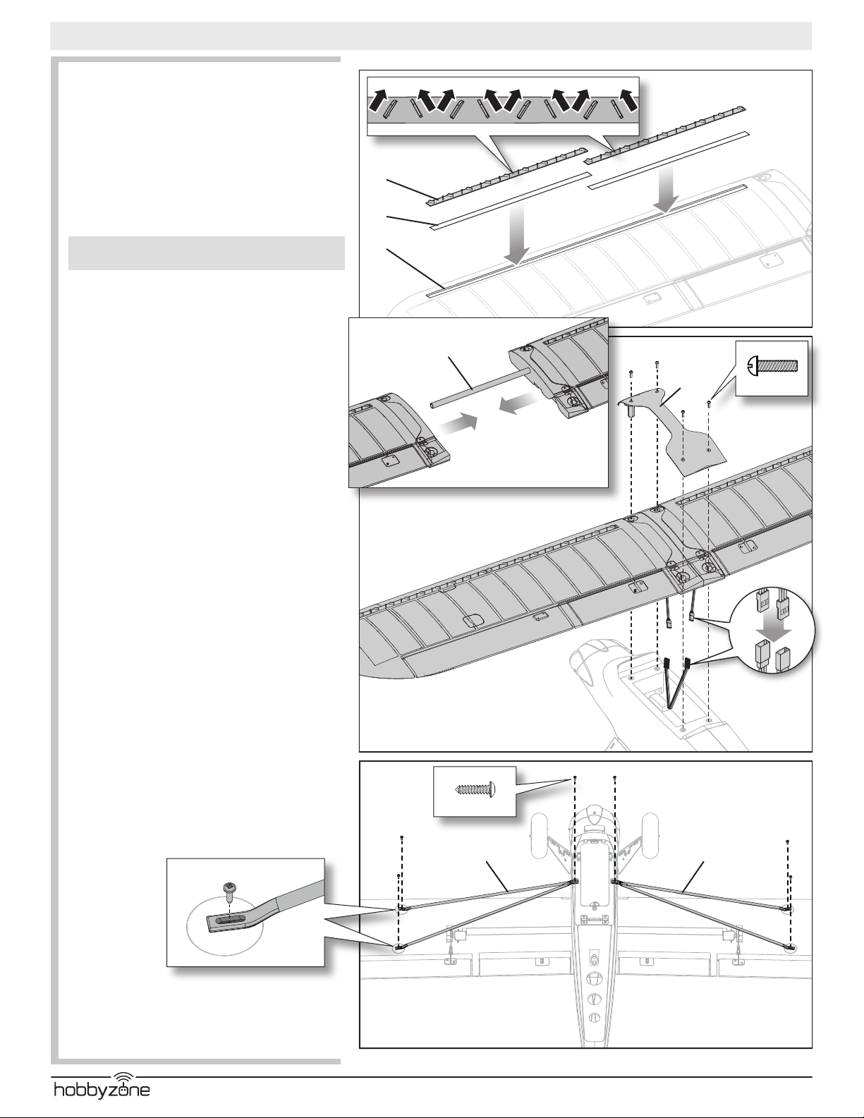
Install the Wing
Assembly
1. Install the vortex generators (A) in the wing channels
(B) by using double-sided tape (C).
2. Slide the wing tube (D) in the hole in the left wing.
3. Slide the other end of the wing tube into the hole in the
right wing until both wings meet.
4. Install the wing cover (E) on the top of the wing, aligning
the 4 holes as shown.
Installation
NOTICE: DO NOT crush or otherwise damage the wiring
when attaching the wing to the fuselage.
1. Connect the left aileron servo connector to the servo
extension labeled “AIL-L”, and connect the right aileron
servo connecter to the servo extension labeled “AIL-R”.
2. Attach the assembled wing and wing cover (E) to the
fuselage using 4 screws (F).
3. Attach the right (G) and left (H) struts (marked R and L)
under the wing and fuselage using 6 screws (I). Adjust
the position of the 4 screws in the top of the strut slots
so the wings are not exed down or twisted.
Disassemble in reverse order.
Carbon Cub S2
A
C
B
D
E
F
3 X 12mm (4)
I
2.5 X 10mm (6)
G
L-AIL
R-AIL
H
®
10
Page 11
Carbon Cub S2
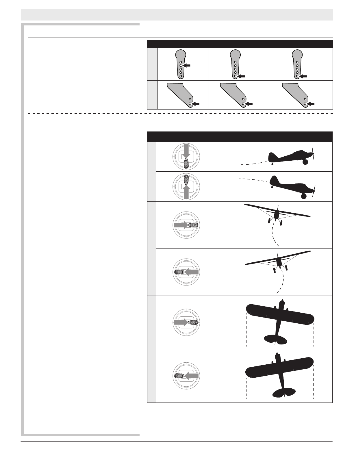
Factory Settings for the Control Horns and Servo Arms
The Illustration shows recommended hole settings in the
servo arms and control horns.
ArmsHorns
Elevator Ailerons Rudder
Flight Control
EN
For smooth control of your aircraft, always make small
corrections. All directions are described as if you were
sitting in the aircraft.
• Flying faster or slower: When your aircraft is stable in
the air, push the throttle stick up to make the aircraft
go faster. Pull the throttle stick back to slow down. The
aircraft will climb when the throttle is increased.
• Elevator up and down: Push the elevator stick forward
to make the aircraft go down. Pull the elevator stick
back to go up.
• Aileron right and left: Move the aileron stick right to
make the aircraft roll or “bank” right. Move the aileron
stick left to bank left.
TIP: Always picture yourself in the aircraft when
determining which way to bank the aircraft wings.
When the aircraft is ying away from you, banking
the aircraft right or left appears normal. When ying
toward you, the aircraft will appear to bank the opposite
direction to the control input given. This will become
more instinctual with experience.
• Rudder left and right: Push the rudder stick left or right
to yaw or point the nose of the aircraft left or right. The
rudder stick is also used to steer the aircraft left and
right while taxiing on the ground.
TIP: Similar to the tip given for the aileron control, picture yourself in the aircraft to determine which direction
to point the nose depending on whether you are ying
away from yourself or toward yourself.
For rst ights, set the SAFE® ight mode switch to Begin-
ner Mode (position 0).
IMPORTANT: Even though SAFE technology is a very
helpful tool, the aircraft still needs to be own manually.
If incorrect input is given at lower altitudes or at slower
speeds, the aircraft can crash. Study these control inputs
and the aircraft response to each carefully before attempting your rst ight.
Transmitter command Aircraft Response
ElevatorAileronRudder
11
RTF/BNF Basic
Page 12
EN
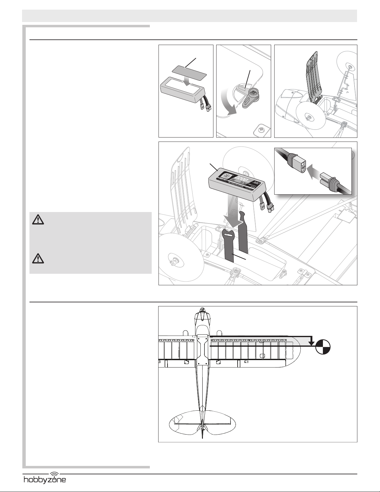
Install the Flight Battery
Battery Selection
• We recommend the E-ite® 2200mAh 11.1V 3S 30C
Li-Po (SPMX22003S30).
• If using another battery, the battery must be at least a
2200mAh battery.
• The battery should be approximately the same capacity,
dimensions and weight as the E-ite Li-Po battery to t
in the fuselage without changing the center of gravity a
large amount.
1. Lower the throttle stick to the lowest setting and center
the throttle trim. Power on the transmitter, then wait 5
seconds.
2. Apply a strip of hook tape (A) to the bottom the battery
near the end opposite the battery wires.
3. Turn the latch (B) and open the battery hatch.
4. Install the ight battery as shown. See the Adjusting the
Center of Gravity instructions for more information.
5. Make sure the ight battery is secured using the hook
and loop strap (D).
6. Connect the battery to the ESC. Close the hatch and turn
the aircraft over and place it on its wheels. Keep the
aircraft immobile and away from wind for 5 seconds.
7. Keep the aircraft immobile for 30+ seconds until GPS
lock is established as described in the Flying section.
CAUTION: Always disconnect the Li-Po ight
battery from the aircraft when not ying to avoid
over-discharging the battery. Batteries discharged to
a voltage lower than the lowest approved voltage may
become damaged, resulting in loss of performance and
potential re when batteries are charged.
CAUTION: Always keep hands away from the
propeller. When armed, the motor will turn the
propeller in response to any throttle movement.
Carbon Cub S2
A
B
C
D
Center of Gravity (CG)
An aircraft with the correct CG has its weight balanced on
the center of the aircraft for safe, stable ight.The aircraft
CG and weight are based on an E-ite 11.1V 2200mAh
30C battery (SPMX22003S30) installed. Make sure the
ight battery is secured using the hook and loop strap.
The CG location is 62-68mm back from the leading edge
of the wing at the root. Balance the aircraft on your ngertips near the fuselage under the wings.
• If the nose goes down, move the ight battery back
until the aircraft balances.
• If the nose goes up, move the ight battery forward
until the aircraft balances.
When in intermediate and experienced modes, if the
aircraft CG is too far forward (nose heavy), up elevator is
required to y level at 50%– 60% power. If the aircraft CG
is too far aft (tail heavy), down elevator is required to y
level. In Beginner mode the aircraft is not affected. The
SAFE system controls the aircrafts attitude.
Adjust the battery position as needed.
®
62–68mm
2.40–2.70 inches
back from the
leading edge of the
wing at the root.
12
Page 13

Control Direction Test
Carbon Cub S2
EN
WARNING: Do not perform this or any other
equipment test with the propeller installed on the
aircraft. Serious injury or property damage could result
from the motor starting inadvertently.
If performing the control direction test indoors, disable
GPS as shown in Deactivating GPS before performing the
control direction test.
Set the SAFE ight mode switch to Experienced mode
(position 2).
Keep the throttle at zero and place the model on level
ground away from obstacles.
Move the sticks on the transmitter as described in the
table to ensure the aircraft control surfaces respond as
shown.
If the control surfaces do not respond as shown, DO NOT
FLY. Refer to the Troubleshooting Guide for more informa-
tion. If you need more assistance, contact the appropriate
Horizon Hobby Product Support department.
If the aircraft responds as shown, continue on to the Flight
Control section.
Transmitter command Control Surface Response
ElevatorAileronRudder
13
RTF/BNF Basic
Page 14

EN
Range Test
WARNING: Do not perform this or any other
equipment test with the propeller installed on
the aircraft. Serious injury or property damage could
result from the motor starting inadvertently.
WARNING: While holding the aircraft during the
range test, always keep body parts and loose
items away from the motor. Failure to do so could cause
personal injury.
Before each ying session, and especially with a new
model, you should perform a range check. If you have the
BNF aircraft, refer to your transmitter manual to perform a
range check of your system.
The included transmitter incorporates a range check mode
to reduce the output power of the transmitter. Follow
the directions below to enter range check mode for the
transmitter:
1. Power on the transmitter for 5 seconds or more with
the throttle stick low and throttle trim centered.
2. Power on the aircraft, keeping it immobile for 5
seconds. The elevator will slowly move up and down,
indicating the aircraft is searching for GPS lock.
3. Turn the GPS function off by pressing and holding the
bind button and fully cycling the ight mode switch 3
times. The elevator movement will stop and the rudder
will wag, indicating GPS is off.
4. Release the bind button.
5. Face the model with the transmitter in your normal
ying position.
6. Toggle the HI/LO Rate switch rapidly 4 times and
then press and hold the bind button. The transmitter LEDs will ash and the alarm will sound. The system is in range check mode. Do not let go of the bind
button until you are nished with the range check.
IMPORTANT: You must hold the BIND button during
the entire range check process. Releasing the button will
immediately exit the range check mode and you will need
to start again.
7. With the radio system powered on and the model
safely restrained on the ground, stand 28 meters
(90 feet) away from the model.
TIP: In some aircraft, when the model is placed on the
ground, the antenna(s) can be within inches of the ground.
Close proximity of the antenna(s) to the ground can reduce
the effectiveness of the range check. If you experience
issues during the range check, restrain the model on a
non-conductive stand or table up to 2ft (60cm) above the
ground, then range check the system again.
8. Move the transmitter rudder, elevator, aileron and
throttle controls to ensure they operate smoothly at
28 meters (90 feet).
9. If control issues exist, do not attempt to y. Refer
to the contact table at the end of the this manual to
contact Horizon Hobby product support. Also, see the
Spektrum website for more information.
10. When the range check is successfully completed,
release the bind button to exit range check mode.
CAUTION: Never attempt to y while the trans-
mitter is in range check mode due to reduced
output power of the transmitter. Loss of control will
occur.
Carbon Cub S2
4X
HOLD
28 meters (90 feet)
®
14
Page 15

Compass Calibration Procedure
Perform the compass calibration before the rst ight
or to correct the heading during auto landing if it varies
signicantly from the heading set during takeoff.
1. Remove the propeller if it is installed or activate
throttle cut.
2. Power on the receiver and set the model on the
ground on its wheels.
3. With the transmitter trims centered, power on the
transmitter and the aircraft while holding the transmitter sticks as shown. The aircraft will indicate the
GPS is searching for satellites by cycling the elevator
up and down.
4. After satellites are acquired, the aircraft will signal
it has entered compass calibration mode by the
following:
Wings on: The ailerons will cycle left and right slowly.
Wings off: The red and blue LEDs on the ight
controller will ash alternately.
Once in calibration mode, the throttle is not active and
the transmitter sticks can be released. The transmitter
must remain powered on.
5. Once in calibration mode, rotate the aircraft twice in
position 1.
6. Turn the aircraft 90 degrees and rotate it twice in
position 2.
7. Turn off the transmitter.
8. Wait 3 seconds and disconnect the ight battery.
Carbon Cub S2
EN
2x 2x
Position 2Position 1
Choose a Flying Field
Consult local laws and ordinances before choosing a
location to y your aircraft.
In order to have the most success and to protect your
property and aircraft, it is very important to select a place
to y that is very open.
Remember, your aircraft can reach signicant speeds
when ying and can cover ground quickly. Plan on ying
in an area that gives you more space than you think you
need, especially with rst ights.
The site should:
• Have a minimum of approximately 1300 feet (400m)
of clear space in all directions.
• Be clear of people and pets.
• Be free of trees, buildings, cars, power lines or anything
that could entangle your aircraft or interfere with your
line of sight.
1300feet
(400 m)
Stand here
Wind
(0–19km/h)
Fly in this area
(upwind of pilot)
0–12 mph
15
RTF/BNF Basic
Page 16

EN
A
Carbon Cub S2
Install the Propeller
WARNING: Do not install the propeller until the aircraft has been
completely assembled, all systems have been checked thoroughly
and you are located at a suitable ying site.
Follow the instructions below to install the propeller and spinner:
1. Install the spinner backplate (E) over the motor shaft, making sure the
notched outer ring is facing forward.
2. Install the propeller (D) against the spinner backplate, lining up the
notches in the propeller with the ribs on the backplate. The numbers on
the propeller should face forward.
3. Using an adjustable wrench, tighten the propeller nut (C) against the
propeller. The nut should be tightened enough to not allow the propeller
to loosen during ight, but not so tight as to damage the propeller or
motor shaft.
4. Line the spinner (B) up and t against the backplate, making sure to t
the lip of the spinner into the notch in the backplate.
5. Install the M2.5 X 8 mm screw (A) in the front of the spinner, threading it
into the end of the motor shaft, securing the spinner to the backplate.
Preight Checklist
1. Find a safe and open ying area
2. Charge ight battery
3. Install fully charged ight battery in aircraft
4. Make sure linkages move freely
5. Perform control direction test
6. Perform a range check
7. Perform the compass calibration
8. Plan ight for ying eld conditions
9. Set a ight timer for 6–8 min.
10. Install the propeller
11. Have fun!
E
C
B
D
Trimming the Aircraft
Adjusting Trim in Flight
The SAFE ight mode switch should be set to
Experienced mode (position 2) before adjusting the trims.
Trimming is best done in calm wind conditions.
If your aircraft does not y straight and level at half throttle
with the sticks at neutral, y into the wind and adjust the trim
sliders as indicated in the table until the aircraft maintains a
reasonably straight and level ight path.
After the aircraft is trimmed in ight, land the aircraft and
proceed to the Manually Adjusting Trim section to set the trim
mechanically.
The included transmitter features electronic trim buttons.
The transmitter emits a faint beep with each click of
the trim buttons in either direction. Holding the button
in either direction quickly adjusts the trim several steps
until the button is released or until the trim reaches the
end of its travel. If the trim button does not beep when
clicked, the trim is at the far end of its travel. Center trim
is indicated by a slightly louder beep.
Aircraft Drift Trim Required
Elevator Trim
Elevator
Elevator Trim
Aileron Trim
Aileron
Aileron Trim
Rudder Trim
Rudder
Rudder Trim
®
16
Page 17

Manually Adjusting Trim
WARNING: Do not perform any maintenance
with the propeller installed on the aircraft.
Serious injury or property damage could result from the
motor starting inadvertently.
The SAFE ight mode switch should be set to
Experienced mode (position 2) before manually adjusting
the trim settings.
The aircraft should be kept still while perfoming manual
adjustment of trim.
With the trim settings from the trim ight still set in the
transmitter, take note of the positions of each of the
control surfaces, one at a time.
Adjust the clevis on each control surface to position the
surface the same as it was with the trim offset.
1. Remove the clevis from the control horn.
2. Turn the clevis (as shown) to lengthen or shorten the
pushrod.
3. Close the clevis onto the control horn and slide the tube
towards the horn to secure the clevis.
4. Move to the next control surface.
When you have all of the surface trims centered, return
the trim settings on the transmitter to neutral by pushing
the trim buttons for each surface until the transmitter
emits a loud beep indicating center trim.
Carbon Cub S2
EN
Flying
Technology Flight Modes
Change between SAFE ight modes by changing the ight
mode switch position.
Beginner Mode (Position 0):
• Below approx. 50 feet (15m), pitch (nose up and down)
and roll (wing tips up and down) angles are limited to
help you keep the aircraft airborne.
• Above approximately 50 feet (15m), pitch and roll control
are increased slightly.
• At any time release both sticks to activate
panic recovery mode for self-leveling.
• Altitude limit of 400 feet.
Intermediate Mode (Position 1):
• Same as beginner mode, with greater pitch control
above approximately 50 feet (15m).
• Above 50 feet (15m) self leveling is not active.
• Self-leveling is active below 50 feet.
• Altitude limit of 400 feet.
Experienced Mode (Position 2):
• Unlimited Flight Envelope.
• Switch to beginner mode at any time and release the
control sticks for self-leveling.
NOTICE: If the aircraft is upside down when the self
leveling is applied, sufcient altitude is required for the
aircraft to return to straight and level ight.
RollPitch
Beginner Mode
(Switch Position 0)
RollPitch
Intermediate Mode
(Switch Position 1)
RollPitch
Experienced Mode
(Switch Position 2)
17
RTF/BNF Basic
Page 18

EN
Carbon Cub S2
Takeoff
Set the ight mode switch to Beginner Mode (position 0) for
your rst ights.
Set a ight timer for 6–8 minutes.
Ground Launch
Once you have established a home position and the aircraft
is ready for ight, slowly advance the throttle to start the
takeoff roll into the wind. Small rudder inputs may be
required for heading correction as the aircraft will begin a
slow climb out as the throttle is advanced.
Hand Launch
Once you have established a home position and the aircraft
is ready for ight, use the following steps.
1. Grip the aircraft under the fuselage, behind the wing
struts.
2. Slowly advance the throttle to 100%.
3. Throw the aircraft slightly nose up and directly into the
wind (less than 5–7 mph [8–11km/h]).
Wind
Slowly advance
the throttle stick.
Wind
Slowly advance
the throttle stick.
In Flight
Let the aircraft climb at full throttle, into the wind, until the
aircraft gets about 300 feet (91m) above the ground, then
decrease the throttle to half (50%).
Make small and gentle stick movements to see how the
aircraft responds.
Flying with the nose pointed toward you is one of the hardest things to do when learning to y. Practice ying in large
circles high off the ground.
If you lose orientation of the aircraft, release both sticks
and the aircraft will return to level ight. If in Intermediate
or Experienced Mode, switch to Beginner Mode and then
release both sticks.
Low Voltage Cutoff (LVC)
LVC is a function built into your ESC to protect the battery
from over-discharge. When the battery charge is low,
LVC limits power supplied to the motor. The aircraft will
begin to slow and you will hear the motor pulse. When the
motor power decreases, land the aircraft immediately and
recharge the ight battery.
NOTICE: Repeated ying to LVC will damage the battery.
Disconnect and remove the Li-Po battery from the aircraft
after use to prevent trickle discharge. Charge your Li-Po
battery to about half capacity before storage. During
storage, make sure the battery charge does not fall below
3V per cell.
When properly trimmed, the aircraft’s wing design causes a climb at full throttle
without the use of elevator.
50% throttleFull throttle Reduced throttle
®
18
Page 19

Landing
Landing Manually
If it is necessary to land the aircraft manually:
1. Reduce the throttle to around 50% to slow the
airspeed.
2. Fly the aircraft downwind past the end of the runway.
3. Turn the aircraft into the wind and line the aircraft up
with the runway center line.
4. Decrease the throttle further and begin descending
towards the runway, keeping the wings level during
approach. Try to have the aircraft at 10ft altitude as it
passes over the threshold of the runway.
5. As the aircraft passes over the threshold of the runway decrease the throttle fully.
6. Just as the aircraft is about to touch down, gently pull
back on the elevator to raise the nose and air for a
gentle landing.
NOTICE: If a crash is imminent, activate throttle hold or
quickly lower the throttle and throttle trim. Failure to do
so could result in extra damage to the airframe, as well
as damage to the ESC and motor.
IMPORTANT: When nished ying, never keep the aircraft
in the sun. Do not store the aircraft in a hot, enclosed area
such as a car. Doing so can damage the foam.
Carbon Cub S2
65ft (20m)
EN
Wind
10ft power is cut
Post Flight Checklist
1. Activate Throttle Cut
2. While avoiding the area of the propeller and prop arc, disconnect the ight battery from the aircraft (Required for Safety)
3. Remove the ight battery from the aircraft
4. Power off the transmitter
5. Recharge the ight battery
6. Inspect the airframe for loose or damaged parts
7. Repair or replace all damaged parts
8. Store ight battery apart from aircraft and monitor the battery charge
9. Make note of ight conditions and ight plan results, planning for future ights
19
RTF/BNF Basic
Page 20

EN
Installing Optional Flaps
Carbon Cub S2
IMPORTANT: The optional aps for this aircraft require a
computer transmitter with at least 7 channels*. The RTF DXS
transmitter is not compatible with the optional aps.
The optional aps should be installed before installing the wing.
1. Slide a silicone tube on each clevis (Fig. 1).
2. Connect the ap servo (PKZ1090, sold separately) to a
servo extension (PKZ5403, sold separately).
3. Connect the servo extension to the AUX2 port of the ight
controller.
4. Install the ap servo (A) in the pocket (B) using hot glue or
double-sided tape.
5. Power on the transmitter.
6. In the Channel Input Conguration menu of the Channel
Assign section of the System Setup list of your computer
radio, assign AUX2 to an available 3-position switch, usually switch D.
7. Move the assigned ap switch to the up position.
8. Install the servo arm on the servo at the angle shown (Fig. 2).
9. Install the ap linkage in the outermost hole of the ap
servo arm (Fig.B).
10. Attach the clevises to the ap torque rods as shown (Fig. 3).
11. On both aps, carefully cut a small amount of foam at the
ap hinge (C) and wing root (D) so the aps move freely
(see illustration).
12. Do a control test of the aps using your aircraft and transmitter. Make sure both aps are symmetrical while they are
retracted and extended.
See the table below for the required ap throws:
1/2 or Takeoff Full
Flap Down 12mm down 25mm down
A
B
C
The RTF DXS transmitter is not compatible with the optional aps. The optional
aps for this aircraft require a computer transmitter with at least 7 channels.
Fig. 1
Fig. 2
Fig. 3
D
See the Spektrum RC website (www.spektrumrc.com) for available ap TX download.
PNP Receiver Selection and Installation
SRLX DSMX Receiver and Flight Controller
Installation
Install the Spektrum SRLX DSMX receiver and ight controller
combination to experience the Carbon Cub S2 with SMART
Technology.
1. Using double-sided servo tape, (not included) mount the
SRLX DSMX receiver (A) to the interior side panel of the
receiver compartment.
2. Connect the SRLX DSMX receiver to the ight controller (B).
3. Attach the appropriate control surfaces to the their
respective ports on the ight controller using the table at
the right.
4. Using double-sided servo tape, (not included) attach the
ight controller to the platform at the rear of the receiver
compartment as shown.
Mount the ight controller in the orientation shown, parallel to
the length of the fuselage, with the label facing up and the servo
ports facing the rear of the aircraft. The orientation of the ight
controller is critical for all AS3X® and SAFE® technology setups.
CAUTION: Incorrect installation of the ight controller
could cause a crash.
A
B
BIND
1 = ESC (Standard)
2 = Left Aileron
3 = Right Aileron
4 = Elevator
5 = Rudder
6 = SMART ESC
7 = Open / Optional LAS
8 = Open / Optional Flaps
®
20
Page 21

Carbon Cub S2
Flying With the Optional Float Set (HBZ7390)
EN
To y this aircraft off water, install the optional
HobbyZone® Float Set (HBZ7390, sold separately). Float
struts, strut brackets and 4 screws are included with the
aircraft. Rear bracket screws are included with the oats.
Follow the instructions included with the optional oat set
to install them to the aircraft.
Only install the oats if you are comfortable ying your
aircraft and have repeatedly taken off, own and landed
with success. Flying off water poses a higher risk to the
aircraft because the electronics can fail if fully immersed
in water.
Always ensure the oats are correctly secured to the
fuselage prior to taxiing or attempting takeoff.
To take off from water, steer with the rudder to turn into
the wind and slowly increase the throttle. Keep the wings
level on takeoff. Hold a small amount (1/4–1/3) of up
elevator and the aircraft will lift off once ying speed is
reached.
To land this aircraft on water, y to a couple of feet off the
surface of the water. Reduce throttle and add up elevator
to are the aircraft.
When taxiing, you must use throttle to move the aircraft
forward, but steer with the rudder stick.
Avoid taxiing cross wind if there is a breeze, as this can
cause the aircraft to ip over if wind gets under the
upwind wing. Taxi 45 degrees into the direction of the
wind (not perpendicular to the wind) and use aileron to
hold the upwind wing down. The aircraft will naturally try
to face into the wind when taxiing.
Always fully dry the aircraft after landing on water.
CAUTION: Never go alone to get a downed
model in the water.
CAUTION: If at any time water splashes in
the fuselage while ying from water, bring
the airplane to shore, open the battery hatch and
immediately remove any water that may have gotten
in the fuselage. Leave the battery hatch open overnight
to let the inside dry and to prevent moisture damage to
the electronic components. Failure to do so could cause
the electronic components to fail, which could result in
a crash.
Up
Aileron
Down
Aileron
Wind
Direction
45º
Taxi 45 degrees into the direction of the wind.
21
RTF/BNF Basic
Page 22

EN
Carbon Cub S2
Service and Repairs
WARNING: Do not perform this or any other equipment maintenance with the propeller installed on the aircraft. Serious injury or property damage could
result from the motor starting inadvertently.
NOTICE: Crash damage is not covered under warranty.
NOTICE: After any impact or replacement always ensure the ight controller/GPS module is secure in the fuselage. If you replace the ight controller, install
the new ight controller in the same location and orientation as the original or damage may result.
Thanks to the Z-Foam™ material in your aircraft, repairs to the foam can be made using virtually any adhesive (hot glue, regular CA [cyanoacrylate adhesive], epoxy, etc).
Use of CA accelerant on the aircraft can damage paint. DO NOT handle the aircraft until accelerant fully dries.
When parts are not repairable, see the Replacement Parts list for ordering by item number.
Service of Power Components
WARNING: Always
disconnect the ight
battery from the model before removing the propeller.
Disassembly
1. Remove the screw (A) and
spinner (B).
2. Use an adjustable wrench
to remove the hex nut
(D), propeller (E), spinner
backplate (F), thrust plate
(G) and collet (C) from the
motor shaft (H).
3. Remove the 3 screws (I)
from the cowl (J). Carefully
remove the cowl from the
fuselage.
4. Remove the 4 screws (K)
holding the motor mount
(L) to the fuselage.
5. Disconnect the motor wires from the ESC wires.
6. Remove the 4 screws (M) holding the motor (N) to the
motor mount.
Assemble in reverse order.
Assembly Tips
• Correctly align and connect the motor wire colors with
the ESC wires.
• The propeller size numbers (9 x 6) must face forward
from the motor for correct propeller operation.
• Ensure the lip of the spinner ts completely into the
notch of the spinner backplate for safe operation.
Not all wiring shown.
D C N
E J
A B F L MH
G I
K
®
22
Page 23

Carbon Cub S2
Optional Landing Assist Sensor (LAS) Upgrade
The Carbon Cub S2 is upgradable with the addition of the optional LAS
module (SPMA3180 not included) this allows the advanced SAFE features
to be combined with an Landing Assist Sensor (LAS) for smoother gentler
landings.
EN
IMPORTANT: For best results when using LAS, land on grass surfaces or a
light colored surface, such as light colored concrete. Black surfaces or water
normally do not have enough reection for the sensor to receive accurate
readings.
Installation of the LAS module
1. Remove the wing to gain access to the ight controller compartment.
2. Rotate the aircraft to access the bottom of the fuselage.
3. Press the factory installed plug (A) to release it. Then removed it from
the LAS pocket. Save the plug for ights without LAS module.
4. Feed the LAS connector through the channel in the base of the LAS
pocket.
5. Align the LAS module with the wires facing the back of the aircraft. Place
the LAS module into the pocket and press it to secure it into place with
a click.
6. Place the aircraft on its landing gear and connect LAS connector to
Channel 7 on the ight controller. For correct polarity of the plug ensure
that the orange (not brown) signal wire (B) is facing towards the front of
the aircraft when plugged into the ight controller.
Landing with LAS
Reduce throttle, keep the wings level and slowly reduce the altitude of the
aircraft. When the aircraft’s landing approach reaches an altitude of roughly
1m the LAS will level off the aircraft, manage the throttle and then are the
aircraft for touchdown.
A
IMPORTANT: LAS is functional for all SAFE ight modes except for
Experienced Mode. When the ight mode is switched to Experienced mode
the LAS is deactivated and the pilot will have zero assistance on landing, a
traditional manual landing of the aircraft is necessary.
IMPORTANT: Installation of the LAS module is not auto land. The aircraft
must be guided and aligned with the landing strip for landing.
LED Indicator
When the LAS module is installed the aircraft’s LED indicator for beginner
and intermediate ight modes will be followed with a purple ash to indicate
that the LAS System is active.
LAS with GPS
With GPS installed LAS will assist the Auto Land mode during landing of the
aircraft. When the aircraft’s landing approach reaches an altitude of roughly
1m the LAS will level off the aircraft, manage the throttle and then are the
aircraft for touchdown.
TIP: If the speed of aircraft is too fast for landing or above 20% throttle
setting, LAS is not effective.
TIP: LAS is not active in Experienced mode.
B
LAS
23
RTF/BNF Basic
Page 24

EN
GPS
Front
Carbon Cub S2
Optional SAFE+ GPS Upgrade
From the Box to the Air
Adding the SAFE+ GPS Module
The Carbon Cub S2 ight controler includes SAFE technology out of the box.
The Carbon Cub S2 ight controler is upgradable with the addition of the
optional SPMA3173 GPS module (not included) which enables advanced
SAFE+ features. With SAFE+, the aircraft can y a holding pattern on its
own, return home and land by itself, and prevent the model from ying too
far from the pilot.
IMPORTANT: Read the information in this manual covering the optional
SAFE+ GPS upgrades, and learn the use of Holding Pattern and Autoland
modes before ying with GPS. SAFE+ features are only available with the
SAFE+ module installed and properly calibrated.
Follow the steps to add SAFE+ functions to your aircraft.
1. Charge the ight battery.
2. Set up your transmitter (BNF only).
3. Install the GPS module.*
4. Find a safe and open area.
5. Power the model on outdoors and perform the compass
calibration.
6. Unplug the battery after the compass calibration is complete.
7. Power the model on and allow it to acquire a GPS lock. The
elevator will move up and down until GPS lock is acquired, and
then re-center.
8. Set the home position (and ying eld location for ying eld
mode). IMPORTANT: Do not y at this time.
9. Place the aircraft into Experienced mode (Mode switch
position 2) for the control direction test. Place the aircraft on
the ground facing away from you.
10. Perform Control Direction Test.
11. Place the aircraft into Beginner mode (Mode switch
position 0) and cycle the throttle to activate SAFE.
12. Perform SAFE Control Direction Test.
13. Plan ight for ying eld conditions.
14. Set a ight timer for 8-10 minutes.
15. Have fun!
GPS Module Installation
1. Verify the battery is not connected or installed in the aircraft.
2. Open the lid of the GPS pocket and feed the cable from the GPS module
through the hole in the base of the GPS pocket.
3. Install the GPS module in the pocket with the label facing up and the
arrow pointing forward.
4. Close the pocket door securing the GPS module in to place.
5. Pull the connector across the electronic compartment and connect it to
the port labeled GPS on the front side of the ight controller. Prevent the
cables from interfering with the servos.
IMPORTANT: Do not kink or cut the GPS antenna cable. Kinks or cuts will
degrade performance.
GPS
®
24
Page 25

Carbon Cub S2
Compass Calibration
Compass calibration might be required after installing the GPS module,
before ight. The aircraft will automatically enter compass calibration on the
rst power up after the GPS module is installed, after binding.
IMPORTANT: The aircraft must be outside and needs to acquire a GPS lock
in order to begin compass calibration. The aircraft will not enter compass
calibration mode until the GPS lock is established.
Perform the compass calibration before the rst ight or to correct the
heading during auto landing if it varies signicantly from the heading set
during takeoff.
Before calibration GPS lock must be established for your location:
1. Remove the propeller if it is installed or activate throttle cut.
2. Powe ON the transmitter and receiver and set the model on the ground
on its wheels. The aircraft’s elevator will slowly move up and down until
GPS lock is established. When nished the elevator will move up and
down once quickly and center.
3. Power OFF the receiver and then the transmitter.
EN
Once initial GPS lock is established Compass Calibration can be
performed.
1. With the transmitter trims centered, power ON the transmitter and the
aircraft while holding the transmitter sticks as shown. The aircraft will
indicate the GPS is searching for satellites by cycling the elevator up
and down. Continue to hold the transmitter sticks as shown.
2. After satellites are acquired, the aircraft will signal it has entered
compass calibration mode by the following:
-The ailerons will cycle left and right slowly.
-The LED will ash red and blue.
3. Once in calibration mode, the throttle is not active and the transmitter
sticks can be released. The transmitter must remain powered ON.
4. Flip the aircraft twice nose over tail as shown.
5. Turn the aircraft 90 degrees and roll the aircraft twice, as shown.
6. Turn off the transmitter.
7. Wait 3 seconds and turn OFF the aircraft.
CAUTION: Keep aircraft away from magnetic sources such as
cameras, camera mounts, speakers etc. These may interfere with
the GPS system and loss of control may result.
Compass Error (LED Flashing Red and Blue)
If at any time you experience no throttle response after power up and the
ailerons are deected full right and the LED is ashing red and blue, the
aircraft is indicating a compass error. This may be due to a lost GPS signal
or from powering on the aircraft at a new ying location. Disconnect the
ight battery and perform the compass calibration procedure.
2 Full Rotations
2 Full Rotations
25
RTF/BNF Basic
Page 26

EN
Powering ON, GPS Initialization and Establishing
Home Location
CAUTION: Keep aircraft away from magnetic sources such as
cameras, camera mounts, speakers etc. These may interfere with
the GPS system and loss of control may result.
1. Power on the transmitter.
2. Install a fully charged ight battery, following the instructions in the
Install the Flight Battery section.
Carbon Cub S2
Aireld Virtual Fence:
Set the home location
and aircraft heading
3. Plug the battery into the aircraft. The elevator will move up and down
slowly, indicating the the GPS is searching for satellites. When GPS is
aquired, the elevator will move quickly and then center.
• If you want to change the virtual fence mode, input the transmitter stick
commands as described in the Virtual Fence Mode and GPS section of
the manual. The fence can be changed at any time before the home
point is set.
IMPORTANT: The throttle is active but only slowly pulses the motor, allowing
you to taxi the aircraft. Either taxi to or place the aircraft in the desired home
location, pointing the nose of the aircraft into the wind and the desired
takeoff direction.
4. Once the aircraft is on the ground at the desired home location, and pointed
into the wind, press and hold the HP/AL (bind) button.
• If either of the circle Virtual Fence modes are active or if virtual fence
is off, all control surfaces will wag and the throttle will now operate,
indicating the aircraft is ready for ight.
• If the Aireld Virtual Fence mode is active, only the ailerons will wag
left and right. Release the HP/AL (bind) button.
location you must then indicate where the ying side of the aireld is in
relation to the home location. The throttle will be inactive until the ying
side direction is set. Set the ying side direction by moving the aileron
stick either left or right in the direction of the ying area:
-If the ying side is off the right wing of the aircraft as it sits in the
home location, push the aileron stick right to the stop and release
(as shown in the example). The right aileron will move up and down
indicating right direction has been set.
After setting the home
No-Fly Zone
Flying Area
Home Location
Direction of ight
In this example right aileron would be
applied to set the ying eld side.
-If the ying side is off the left wing as the aircraft sits in the home
location, push the aileron stick left to the stop and release. The left
aileron will move up and down indicating left direction has been set.
Once the home location and ying location is set, all surfaces will wag,
indicating the aircraft is ready for ight.
CAUTION: If the aircraft is in Aireld mode, the line that denes the
no y zone will be aligned with the center line of the aircraft, and
approximately 10 meters behind you to ensure the fence does not interfere
with take-offs or landings. Make sure the aircraft is point directly down the
runway in one direction or the other to correctly set the Aireld mode. If the
aircraft is not aligned with the runway, the no y zone will not be set in the
correct location.
®
26
Page 27

Carbon Cub S2
Flight Modes
Beginner, Intermediate and Experienced modes still operate the same with
SAFE+ as they did with SAFE. With SAFE+, The Holding Pattern (HP) and
AutoLand (AL) modes may be used as well.
Holding Pattern and AutoLand Trigger
Holding Pattern: Press and release the HP/AL (Bind) button. Press and
release the HP/AL (Bind) button again to exit.
AutoLand: Press and hold the HP/AL (Bind) button for 3 seconds. Press and
release the HP/AL (Bind) button again to abort AutoLand.
Changing the ight mode will exit Holding Pattern or AutoLand and resume
manual control in the selected ight mode.
The “I” button is used for these features on BNF models when using the
recommended transmitter setup.
IMPORTANT: LAS is functional for all SAFE ight modes except for Expert
Mode. When the ight mode is switched to Expert mode the LAS is
deactivated and the pilot will have zero assistance on landing, a traditional
manual landing of the aircraft is nessesary.
EN
HP/AL button
Flying the Carbon Cub S2
• Sensor Assisted Flight Envelope (SAFE® Plus) technology
is designed as ight assistance, not an autopilot.
The pilot should y the aircraft at all times.
• Start in Beginner mode (Flight Mode switch position 0). As you learn and
become more condent, change modes to advance your ying skills.
• Fly your aircraft outside in no greater than
winds up to 12 mph (16 km/h).
• Always launch your aircraft directly into the wind if possible.
• When ying in Autoland mode, the aircraft ight path may
be adjusted with the transmitter controls, release the
controls to let the GPS system resume command.
• The Carbon Cub S (V2) with SAFE+ technology added does
not have obstacle avoidance technology, be prepared to guide
the aircraft if it is headed toward a tree or other object.
IMPORTANT: A very large ying area is required for GPS assisted aircraft.
400 meters by 400 meters minimum. (1200' x 1200')
27
RTF/BNF Basic
Page 28

EN
Carbon Cub S2
Virtual Fence Mode and GPS
CAUTION: Keep aircraft away from magnetic sources such as
cameras, camera mounts, speakers etc. These may interfere with
the GPS system and loss of control may result.
Your aircraft uses GPS to establish a home location and a virtual fence to keep
the aircraft within a given distance from the home location. While ying, the
aircraft will automatically turn around and y back towards the home location
if it approaches the edge of the virtual fence. Once back inside the fence, the
aircraft will “wag” its wings, indicating full control has been given back to
the pilot.
The Virtual Fence feature is active in all SAFE ight modes, provided the GPS
function is active. There are 4 variations of Virtual Fence mode, which are
selectable from the transmitter while the aircraft GPS system initializes.
Virtual Fence Off: turns off the Virtual Fence function.
Circle Virtual Fence, Small (Default): sets the virtual fence in a circle with a
radius of approximately 175 meter from the home location.
Circle Virtual Fence, Large: sets the virtual fence in a circle with a radius of
approximately 225 meters from the home location.
Aireld Virtual Fence: sets the virtual fence in a rectangle of approximately
400m long x 200m wide and establishes a “no y zone” approximately 10m
(about 30 feet) inside of the center line.
LED Indication
Virtual Fence Off: Slow yellow ash until home point is set. Once
home point and direction is set, a solid LED (without LAS installed).
Circle Virtual Fence, Small (Default): 1 Red, 1 yellow ash until home
point is set. Once home point and direction set, a solid LED (without
LAS installed).
Circle Virtual Fence, Large: 2 Red, 1 yellow ash until home point set.
Once home point and direction is set, solid LED (without LAS installed).
Aireld Virtual Fence 3 Red, 1 yellow ash Set home, slow yellow
ash. Set direction, right or left aileron depending on direction of ying
eld. Home point and direction set, solid LED without LAS.
*A purple ash will follow all mode indicators to indicate LAS is
installed.
Virtual Fence Mode Transmitter Stick Position
Virtual Fence OFF
• Low throttle
• Full right aileron
• Full up elevator
• LED Indication: Slow Yellow
ash until home point is set.*
Circle Virtual Fence, Small
(Default)
• Low throttle
• Full left aileron
• Full up elevator
• LED Indication: Slow yellow
ash with 1 Red ash.*
Circle Virtual Fence, Large
• Low throttle
• Full left aileron
• Full down elevator
• LED Indication: Slow yellow
ash with 2 Red ash*
Aireld Virtual Fence
• Low throttle
• Full right aileron
• Full down elevator
• LED Indication: Slow Yellow
ash with 3 red ash*
LEDs are located in the center of the front windshield of the aircraft.
*A purple ash will follow all mode indicators to indicate LAS is installed.
Circle Virtual
Fence
Home Location
Small (Default)
Large
Once a Virtual Fence mode is chosen, the aircraft will remember that mode
until another mode is chosen. It is not necessary to select the Virtual Fence
mode every time the aircraft is powered on.
WARNING: Never attempt to y under the no y zone. The bottom
of the no y zone is elevated to only allow for taxiing of the aircraft
in the pit area of the aireld. Due to variances in the barometric sensor,
attempting to y in this area may cause the aircraft to suddenly y back
toward the home location, during which time the pilot will have no control
over the aircraft until the aircraft reaches the home location. The pilot will
have no way to avoid any obstacles between the no y zone and the
home location.
®
Aireld Virtual
Fence
Flying Area
28
No-Fly Zone
above ~20ft (6m)
Home Location
Aircraft Heading
Page 29

Carbon Cub S2
EN
Holding Pattern (HP) Mode
If at anytime the aircraft seems too far away, press and release the HP/AL
(bind) button on the transmitter.
The aircraft will maneuver to an altitude of approximately 120 feet (36m)
and begin to y a circular pattern over the home location.
If Aireld Virtual Fence mode is active, the aircraft will y to approximately
120 ft (36m) altitude and y a circular pattern about 100 ft (30m) in front of
the home location.
The aircraft ies fully autonomously when HP mode is active. The
transmitter sticks have no control.
NOTICE: As a safety precaution, Holding Pattern mode will not function
when your aircraft is below an altitude of approximately 20 ft (6m).
To deactivate HP mode and regain control, press and release the HP/AL
button again or change ight modes.
IMPORTANT: When the HP feature is activated, the aircraft should
immediately respond to the command. If the aircraft does not respond
immediately, GPS signal may have been lost. In this case, the aircraft will
have to be own back to the home location manually.
Failsafe (LED: RED SLOW FLASHING)
If at anytime the aircraft loses radio connection, the aircraft will activate
Holding Pattern mode until it re-establishes radio connection. If radio
connection is not regained, the aircraft will land near the takeoff location as
in AutoLand mode.
Holding Pattern Mode
If radio connection is lost while the aircraft is already in Holding Pattern
Mode, the aircraft will circle for approximately 35seconds and then set up
to land as in AutoLand mode.
NOTICE: If a crash is imminent, activate throttle hold or quickly lower the
throttle and throttle trim. Failure to do so could result in extra damage to
the airframe, as well as damage to the ESC and motor.
Deactivating GPS in Flight
If the GPS system malfunctions while in ight, deactivate it to regain full
manual control.
To deactivate the GPS in ight:
1. Press and hold the HP/AL (bind) button down and fully cycle the
ight mode switch 3 times. The rudder will wag to indicate GPS is
deactivated.
2. Set the ight mode switch to beginner mode for full SAFE Plus function.
The GPS system will remain off until the aircraft is landed and the ight
battery is unplugged and reconnected.
NOTICE: If GPS is deactivated, none of the Virtual Fence modes, Hold
Position mode or Auto Land mode will function. The pilot will have to
manually y the aircraft back to a safe landing.
Holding Pattern Mode,
Aireld Virtual Fence Active
29
RTF/BNF Basic
Page 30

EN
Carbon Cub S2
AutoLand Mode
To activate AutoLand mode, press and hold the HP/AL
(bind) button for 3 seconds. The aircraft will immediately
turn to align itself for an upwind approach and maneuver
to an altitude of approximately 65 ft (20m) and 295 ft (90m)
downwind from the takeoff point. The aircraft will then turn
into the wind and begin the nal approach.
NOTICE: As a safety precaution, AutoLand mode will
not initiate when the aircraft is below an altitude of
approximately 20ft (6m).
IMPORTANT: When the AutoLand feature is activated, the
aircraft will immediately respond to the command. If your
aircraft does not respond immediately, GPS signal may
have been lost. In this case, the aircraft will have to be
own back and landed manually.
The aircraft will land into the wind near your takeoff point
and come to a complete stop.
Press and release the HP/AL (bind) button or change ight
modes at anytime to abort the AutoLand approach.
IMPORTANT: AutoLand mode does not have the ability to
avoid obstacles. Ensure that your ying location is free
of obstacles (trees, buildings, etc) before you start ying.
Remain alert during the AutoLand process in the event it
becomes necessary to assist during or abort the landing
approach.
CAUTION: Never attempt to catch a ying aircraft in your hands. Doing so could cause severe
personal injury and damage to the aircraft.
Hold for 3 sec. to activate
AutoLand mode
65ft (20m)
10ft power is cut
Abort
Wind
Assisting AutoLand Mode
No stick inputs are required when AutoLand is activated. However, stick inputs can be used
at anytime during AutoLand to avoid an obstacle, lengthen the landing or smooth the nal
are on landing.
Aileron stick:
Use the aileron stick to steer left or right to avoid an obstacle or make slight
heading adjsutments when on nal approach. When aileron is given, the throttle will
automatically advance slightly. Release the aileron stick and the system will take over
full control.
Throttle stick:
Use the throttle stick to set a throttle max point. When elevator stick input is given, the
throttle will go to the max point.
Elevator stick:
Up elevator: Allows the aircraft to stretch its approach by gaining altitude. When
up elevator is applied the throttle increases to the throttle max point that you have
established with the throttle stick.
As the aircraft passes over the runway threshold, pull the throttle stick fully back and
use up elevator to are the aircraft to a soft touch down on the runway. This is the best
practice for landings and will help prevent accidental propeller strikes.
Down elevator : Allows the aircraft to stretch its approach without gaining or losing
altitude. When down elevator is applied, the throttle increases to the throttle max point
that you have established with the throttle stick without gaining or losing altitude. As
soon as the right stick is centered, the system will take over full control again.
Example: When landing into a headwind, set the throttle stick to approximately
3/4 power. When the elevator stick is moved to extend the landing approach, the
power will only progress to 3/4 power. Set to a higher throttle point in stronger
wind or lower throttle point in low wind.
®
30
Page 31

Carbon Cub S2
Deactivating GPS
Deactivating GPS in the Air
If for any reason you wish to deactivate the GPS system while the aircraft
is airborne, such as if the GPS system is not calibrated correctly or is not
responding as expected, follow the directions below:
1. Press and hold the HP/AL (bind) button and cycle the ight mode
switch fully 3 times. The rudder will wag, indicating the GPS system is
deactivated.
2. Maintain control of the aircraft and return to the runway to land manually.
To reactivate the GPS system, power cycle the aircraft.
IMPORTANT: When the GPS system is deactivated, the aircraft’s Holding
Pattern, AutoLand and Virtual Fence modes will not function.
Deactivating GPS on the Ground
WARNING: Do not perform this or any other equipment test with
the propeller installed on the aircraft. Serious injury or property
damage could result from the motor starting inadvertently.
EN
The GPS system is activated when the aircraft is powered ON. If for any
reason you wish to deactivate the GPS system, such as to perform a control
direction test indoors or to simply enjoy the aircraft without GPS features,
follow the directions below:
1. Ensure that your transmitter is bound to the aircraft. If necessary, refer to
the Transmitter and Receiver Binding section.
2. Power on the transmitter.
3. Power on the aircraft. After the aircraft nds the RF signal, the elevator
will start to move up and down slowly, indicating the GPS system is
searching for satellites.
4. Press and hold the HP/AL (bind) button and cycle the ight mode switch
fully 3 times. The elevator will stop moving and the rudder will wag,
indicating the GPS system is deactivated.
To reactivate the GPS system, power cycle the aircraft.
IMPORTANT: When the GPS system is deactivated, the aircraft’s Holding
Pattern, AutoLand and Virtual Fence modes will not function.
IMPORTANT: When GPS is deactived from transmitter, LED will ash red
slowly. No other LED indicators will function.
To have LED indicators, unplug GPS from ight controller.
Troubleshooting Guide (SAFE+ GPS Upgrade)
Problem Possible Cause Solution
Aircraft will not respond to throttle but
responds to other controls
Ailerons go up aircraft will not bind to
transmitter (during binding)
Ailerons go up and aircraft will not
respond to transmitter (after binding)
Aircraft will not enter compass
calibration
Motor does not respond after landing
Motor pulses but battery is fully
charged, not an LVC motor pulse
AutoLand was not deactivated after landing
Home location has not been set Set the home location
Direction of Aireld fence has not been set Use aileron command to set the fence location
Transmitter too near aircraft during binding process
Bind switch or button not held long enough during bind process Power off transmitter and repeat bind process
Aircraft or transmitter is too close to large metal object, wireless
source or another transmitter
Aircraft was not placed upright
Less than a 90-second wait between rst powering on transmitter
and connecting ight battery to aircraft
Aircraft was not upright, level or motionless
Aircraft cannot acquire a GPS signal
Aux1 (CH 6) reversed Reverse Aux1
Aircraft cannot acquire a GPS signal
Over Current Protection (OCP) stops the motor when the
transmitter throttle is set high and the propeller cannot turn
AutoLand has not been deactivated
Lost GPS Signal
Deactivate AutoLand by pressing the AL/HP button or
changing ight modes and lower throttle
Power off transmitter, move transmitter a larger distance from
aircraft, disconnect and reconnect ight battery to aircraft and
follow binding instructions
Move aircraft and transmitter to another location and
attempt binding again
Place aircraft upright after powering up
Leaving transmitter on, disconnect and reconnect ight
battery to aircraft
Leaving transmitter on, disconnect and reconnect ight
battery to aircraft assuring that the aircraft is upright, level
and motionless
Turn off GPS
Move to an outdoor location away from metal or concrete
and try again
Move to an outdoor location away from metal or concrete
and try again
Fully lower throttle and throttle trim to arm ESC
Press and release HP/AL button to deactivate AutoLand
feature
Turn off the GPS functions
Try ying at a different location
31
RTF/BNF Basic
Page 32

EN
Carbon Cub S2
AS3X® System Troubleshooting Guide
Problem Possible Cause Solution
Trim change when
ight mode is
switched
Trim is not at neutral To adjust the trim more than 8 clicks, return the trim to neutral and manually adjust the clevis to center the trim
Sub-Trim is not at neutral Do not use Sub-Trim. Adjust the servo arm or the clevis
Troubleshooting Guide
Problem Possible Cause Solution
There is no link between the transmitter and receiver Re-Bind the system following directions in this manual
No GPS lock (or operating indoor without disabling GPS) Move to outside and power on aircraft or disable GPS in the aircraft
Transmitter AA batteries are depleted or installed
Aircraft does not operate
Aircraft keeps turning in one
direction
Aircraft does not land on heading
set on initial takeoff
GPS Function not operating
properly
Aircraft is difficult to control
Aircraft nose rises steeply at half
throttle
Aircraft will not climb
Aircraft difcult to launch in the
wind
Flight time is too short
Aircraft vibrates Propeller, spinner or motor damaged Tighten or replace parts
Rudder, ailerons or elevator do
not move freely
Aircraft will not Bind (during binding) to transmitter
Aircraft will not connect
(after binding) to transmitter
After being properly adjusted,
aileron and/or rudder are not in
neutral position when
battery is plugged in
Virtual Fence modes will
not change between modes
correctly
incorrectly as indicated by a dim or unlit LED on the transmitter
or the low battery alarm
No electrical connection Push connectors together until they are secure
Flight battery is not charged Fully charge the battery
Crash has damaged the radio inside the fuselage Replace the fuselage or receiver
Rudder or rudder trim is not adjusted correctly
Aileron or aileron trim is not adjusted correctly Adjust stick trims or manually adjust aileron positions
Compass is out of calibration
The compass has been exposed to a magnetic source
Wing or tail is damaged Replace damaged part
Damaged propeller Land immediately and replace damaged propeller
Center of Gravity is behind the recommended location
Wind is too gusty or strong Postpone flying until the wind calms down
Elevator is trimmed ‘up’ too much
Battery is not installed in the correct position Move forward approximately 1/2”
Battery is not fully charged Fully charge battery before flying
Elevator may be trimmed ‘down’ Adjust elevator trim ‘up’
Propeller damaged or installed incorrectly Land immediately, replace or install propeller correctly
Launching the aircraft down wind or into a cross wind Always launch the aircraft directly into the wind
Battery is not fully charged Recharge battery
Flying at full throttle for the entire ight Fly at just above half throttle to increase ying time
Wind speed too fast for safe ight Fly on a calmer day
Propeller damaged Replace propeller
Damaged or blocked push rods or hinges Repair damage or blockage
Transmitter is too near aircraft during binding process
Aircraft or transmitter is too near a large metal object, wireless
source or another transmitter
Bind plug is not installed correctly Install bind plug and bind aircraft to transmitter
Flight battery/Transmitter battery charge is too low Replace/recharge batteries
Transmitter is too near aircraft during connecting process
Aircraft or transmitter is too near a large metal object, wireless
source or another transmitter
Bind plug is left installed Rebind transmitter to aircraft and remove bind plug before cycling power
Aircraft battery/Transmitter battery charge is too low Replace/recharge batteries
Transmitter may have been bound to a different model (using
different DSM Protocol)
Model was moved during initial power on
Dual rates set incorrectly in transmitter setup
Check polarity installation or replace with fresh AA batteries
Adjust stick trims, then land and manually adjust aileron and/or rudder linkages
so no transmitter trim is required
Calibrate the compass using the “Compass Calibration Procedure” located in
this manual
Deactivate GPS system while in ight and land the aircraft. Remove any possible
magnetic sources such as cameras, camera mounts, speakers ect. Unplug and
reconnect ight battery to reactivate GPS system for next ight. Perform compass
calibration before ying again.
Shift battery forward, do not y until correct Center of Gravity location is
achieved
If trim must adjusted more than 4 clicks when pushing the trim button, adjust
push rod length
Move powered transmitter a few feet from aircraft, disconnect and reconnect
battery to aircraft
Move the aircraft and transmitter to another location and
attempt binding again
Move powered transmitter a few feet from aircraft, disconnect and reconnect
battery to aircraft
Move the aircraft and transmitter to another location and attempt
connecting again
Bind aircraft to transmitter
Unplug ight battery and reconnect, keeping model immobile for at least 5
seconds
The dual rates should not be set lower than 70% for low rate. Set all low rates
to 70% or higher.
®
32
Page 33

Carbon Cub S2
AMA National Model Aircraft Safety Code
Effective January 1, 2014
A. GENERAL
A model aircraft is a non-human-carrying aircraft capable of sustained ight
in the atmosphere. It may not exceed limitations of this code and is intended
exclusively for sport, recreation, education and/or competition. All model ights
must be conducted in accordance with this safety code and any additional rules
specic to the ying site.
1. Model aircraft will not be own:
(a) In a careless or reckless manner.
(b) At a location where model aircraft activities are prohibited.
2. M odel aircraft pilots will:
(a) Yield the right of way to all man carrying aircraft.
(b) See and avoid all aircraft and a spotter must be used when appropriate.
(AMA Document #540-D.)
(c) Not y higher than approximately 400 feet above ground level within
three (3) miles of an airport, without notifying the airport operator.
(d) Not interfere with operations and trafc patterns at any airport, heliport
or seaplane base except where there is a mixed use agreement.
(e) Not exceed a takeoff weight, including fuel, of 55 pounds unless in
compliance with the AMA Large Model Aircraft program. (AMA Document
520-A.)
(f) Ensure the aircraft is identied with the name and address or AMA
number of the owner on the inside or afxed to the outside of the model
aircraft. (This does not apply to model aircraft own indoors).
(g) Not operate aircraft with metal-blade propellers or with gaseous boosts
except for helicopters operated under the provisions of AMA Document
#555.
(h) Not operate model aircraft while under the inuence of alcohol or while
using any drug which could adversely affect the pilot’s ability to safely
control the model.
(i) Not operate model aircraft carrying pyrotechnic devices which explode
or burn, or any device which propels a projectile or drops any object that
creates a hazard to persons or property.
Exceptions:
• Free Flight fuses or devices that burn producing smoke and are
securely attached to the model aircraft during ight.
• Rocket motors (using solid propellant) up to a G-series size may be
used provided they remain attached to the model during ight. Model
rockets may be own in accordance with the National Model Rocketry
Safety Code but may not be launched from model aircraft.
• Ofcially designated AMA Air Show Teams (AST) are authorized to use
devices and practices as dened within the Team AMA Program Document (AMA Document #718).
(j) Not operate a turbine-powered aircraft, unless in compliance with the
AMA turbine regulations. (AMA Document #510-A).
3. Model aircraft will not be own in AMA sanctioned events, air shows or
model demonstrations unless:
(a) The aircraft, control system and pilot skills have successfully
demonstrated all maneuvers intended or anticipated prior to the specic
event.
(b) An inexperienced pilot is assisted by an experienced pilot.
4. When and where required by rule, helmets must be properly worn and
fastened. They must be OSHA, DOT, ANSI, SNELL or NOCSAE approved or
comply with comparable standards.
EN
B. RADIO CONTROL
1. All pilots shall avoid ying directly over unprotected people, vessels,
vehicles or structures and shall avoid endangerment of life and property of
others.
2. A successful radio equipment ground-range check in accordance with
manufacturer’s recommendations will be completed before the rst ight of
a new or repaired model aircraft.
3. At all ying sites a safety line(s) must be established in front of which all
ying takes place (AMA Document #706.)
(a) Only personnel associated with ying the model aircraft are allowed at
or in front of the safety line.
(b) At air shows or demonstrations, a straight safety line must be
established.
(c) An area away from the safety line must be maintained for spectators.
(d) Intentional ying behind the safety line is prohibited.
4. RC model aircraft must use the radio-control frequencies currently allowed
by the Federal Communications Commission (FCC). Only individuals properly
licensed by the FCC are authorized to operate equipment on Amateur Band
frequencies.
5. RC model aircraft will not operate within three (3) miles of any pre-existing
ying site without a frequency-management agreement (AMA Documents
#922 and #923.)
6. With the exception of events own under ofcial AMA Competition
Regulations, excluding takeoff and landing, no powered model may be
own outdoors closer than 25 feet to any individual, except for the pilot and
the pilot’s helper(s) located at the ight line.
7. Under no circumstances may a pilot or other person touch a model aircraft
in ight while it is still under power, except to divert it from striking an
individual.
8. RC night ying requires a lighting system providing the pilot with a clear
view of the model’s attitude and orientation at all times. Hand-held
illumination systems are inadequate for night ying operations.
9. The pilot of a RC model aircraft shall:
(a) Maintain control during the entire ight, maintaining visual contact
without enhancement other than by corrective lenses prescribed for the
pilot.
(b) Fly using the assistance of a camera or First-Person View (FPV) only in
accordance with the procedures outlined in AMA Document #550.
(c) Fly using the assistance of autopilot or stabilization system only in
accordance with the procedures outlined in AMA Document #560.
Please see your local or regional modeling association’s guidelines for
proper, safe operation of your model aircraft.
33
RTF/BNF Basic
Page 34

EN
Carbon Cub S2
Limited Warranty
What this Warranty Covers
Horizon Hobby, LLC, (Horizon) warrants to the original purchaser that the
product purchased (the “Product”) will be free from defects in materials and
workmanship at the date of purchase.
What is Not Covered
This warranty is not transferable and does not cover (i) cosmetic damage, (ii)
damage due to acts of God, accident, misuse, abuse, negligence, commercial
use, or due to improper use, installation, operation or maintenance, (iii)
modication of or to any part of the Product, (iv) attempted service by
anyone other than a Horizon Hobby authorized service center, (v) Product not
purchased from an authorized Horizon dealer, or (vi) Product not compliant with
applicable technical regulations, or (vii) use that violates any applicable laws,
rules, or regulations.
OTHER THAN THE EXPRESS WARRANTY ABOVE, HORIZON MAKES NO OTHER
WARRANTY OR REPRESENTATION, AND HEREBY DISCLAIMS ANY AND ALL
IMPLIED WARRANTIES, INCLUDING, WITHOUT LIMITATION, THE IMPLIED
WARRANTIES OF NON-INFRINGEMENT, MERCHANTABILITY AND FITNESS
FOR A PARTICULAR PURPOSE. THE PURCHASER ACKNOWLEDGES THAT THEY
ALONE HAVE DETERMINED THAT THE PRODUCT WILL SUITABLY MEET THE
REQUIREMENTS OF THE PURCHASER’S INTENDED USE.
Purchaser’s Remedy
Horizon’s sole obligation and purchaser’s sole and exclusive remedy shall be
that Horizon will, at its option, either (i) service, or (ii) replace, any Product
determined by Horizon to be defective. Horizon reserves the right to inspect
any and all Product(s) involved in a warranty claim. Service or replacement
decisions are at the sole discretion of Horizon. Proof of purchase is required
for all warranty claims. SERVICE OR REPLACEMENT AS PROVIDED UNDER THIS
WARRANTY IS THE PURCHASER’S SOLE AND EXCLUSIVE REMEDY.
Limitation of Liability
HORIZON SHALL NOT BE LIABLE FOR SPECIAL, INDIRECT, INCIDENTAL
OR CONSEQUENTIAL DAMAGES, LOSS OF PROFITS OR PRODUCTION OR
COMMERCIAL LOSS IN ANY WAY, REGARDLESS OF WHETHER SUCH CLAIM IS
BASED IN CONTRACT, WARRANTY, TORT, NEGLIGENCE, STRICT LIABILITY OR
ANY OTHER THEORY OF LIABILITY, EVEN IF HORIZON HAS BEEN ADVISED OF
THE POSSIBILITY OF SUCH DAMAGES. Further, in no event shall the liability of
Horizon exceed the individual price of the Product on which liability is asserted.
As Horizon has no control over use, setup, nal assembly, modication or
misuse, no liability shall be assumed nor accepted for any resulting damage
or injury. By the act of use, setup or assembly, the user accepts all resulting
liability. If you as the purchaser or user are not prepared to accept the liability
associated with the use of the Product, purchaser is advised to return the
Product immediately in new and unused condition to the place of purchase.
Law
These terms are governed by Illinois law (without regard to conict of law
principals). This warranty gives you specic legal rights, and you may also
have other rights which vary from state to state. Horizon reserves the right to
change or modify this warranty at any time without notice.
WARRANTY SERVICES
Questions, Assistance, and Services
Your local hobby store and/or place of purchase cannot provide warranty
support or service. Once assembly, setup or use of the Product has been
started, you must contact your local distributor or Horizon directly. This will
enable Horizon to better answer your questions and service you in the event
that you may need any assistance. For questions or assistance, please visit our
website at www.horizonhobby.com, submit a Product Support Inquiry, or call
the toll free telephone number referenced in the Warranty and Service Contact
Information section to speak with a Product Support representative.
Inspection or Services
If this Product needs to be inspected or serviced and is compliant in the
country you live and use the Product in, please use the Horizon Online Service
Request submission process found on our website or call Horizon to obtain a
Return Merchandise Authorization (RMA) number. Pack the Product securely
using a shipping carton. Please note that original boxes may be included,
but are not designed to withstand the rigors of shipping without additional
protection. Ship via a carrier that provides tracking and insurance for lost or
damaged parcels, as Horizon is not responsible for merchandise until it arrives
and is accepted at our facility. An Online Service Request is available at http://
www.horizonhobby.com/content/service-center_render-service-center. If you
do not have internet access, please contact Horizon Product Support to obtain
a RMA number along with instructions for submitting your product for service.
When calling Horizon, you will be asked to provide your complete name, street
address, email address and phone number where you can be reached during
business hours. When sending product into Horizon, please include your RMA
number, a list of the included items, and a brief summary of the problem. A
copy of your original sales receipt must be included for warranty consideration.
Be sure your name, address, and RMA number are clearly written on the
outside of the shipping carton.
NOTICE: Do not ship LiPo batteries to Horizon. If you have any issue with
a LiPo battery, please contact the appropriate Horizon Product Support
ofce.
Warranty Requirements
For Warranty consideration, you must include your original sales receipt
verifying the proof-of-purchase date. Provided warranty conditions have
been met, your Product will be serviced or replaced free of charge. Service or
replacement decisions are at the sole discretion of Horizon.
Non-Warranty Service
Should your service not be covered by warranty, service will be
completed and payment will be required without notication or estimate
of the expense unless the expense exceeds 50% of the retail purchase
cost. By submitting the item for service you are agreeing to payment of the
service without notication. Service estimates are available upon request. You
must include this request with your item submitted for service. Non-warranty
service estimates will be billed a minimum of ½ hour of labor. In addition you
will be billed for return freight. Horizon accepts money orders and cashier’s
checks, as well as Visa, MasterCard, American Express, and Discover cards. By
submitting any item to Horizon for service, you are agreeing to Horizon’s Terms
and Conditions found on our website http://www.horizonhobby.com/content/
service-center_render-service-center.
ATTENTION: Horizon service is limited to Product compliant in the
country of use and ownership. If received, a non-compliant Product will
not be serviced. Further, the sender will be responsible for arranging
return shipment of the un-serviced Product, through a carrier of the
sender’s choice and at the sender’s expense. Horizon will hold noncompliant Product for a period of 60 days from notication, after which
it will be discarded.
10/15
®
34
Page 35

Carbon Cub S2
Contact Information
Country of Purchase Horizon Hobby Contact Information Address
United States of America
Horizon Service Center
(Repairs and Repair Requests)
Horizon Product Support
(Product Technical Assistance)
Sales
servicecenter.horizonhobby.com/RequestForm/
productsupport@horizonhobby.com
877-504-0233
websales@horizonhobby.com
800-338-4639
2904 Research Rd
Champaign, Illinois, 61822 USA
FCC Information
Contains FCC ID: BRWKATY1T
Contains FCC ID: BRWSRLRR2
This device complies with part 15 of the FCC rules. Operation is subject to the
following two conditions: (1) This device may not cause harmful interference,
and (2) this device must accept any interference received, including
interference that may cause undesired operation.
CAUTION: Changes or modications not expressly approved by the
party responsible for compliance could void the user’s authority to
operate the equipment.
This product contains a radio transmitter with wireless technology which
has been tested and found to be compliant with the applicable regulations
governing a radio transmitter in the 2.400GHz to 2.4835GHz frequency range.
Supplier’s Declaration of Conformity
HBZ Carbon Cub S2 | HBZ32000
This device complies with part 15 of the FCC Rules. Operation is subject to the
following two conditions: (1) This device may not cause harmful interference,
and (2) this device must accept any interference received, including
interference that may cause undesired operation.
CAUTION: Changes or modications not expressly approved by the
party responsible for compliance could void the user’s authority to
operate the equipment.
NOTE: This equipment has been tested and found to comply with the limits
for a Class B digital device, pursuant to part 15 of the FCC Rules. These limits
are designed to provide reasonable protection against harmful interference
in a residential installation. This equipment generates, uses and can radiate
radio frequency energy and, if not installed and used in accordance with
the instructions, may cause harmful interference to radio communications.
However, there is no guarantee that interference will not occur in a particular
installation. If this equipment does cause harmful interference to radio or
television reception, which can be determined by turning the equipment off and
on, the user is encouraged to try to correct the interference by one or more of
the following measures:
• Reorient or relocate the receiving antenna.
• Increase the separation between the equipment and receiver.
• Connect the equipment into an outlet on a circuit different from that to
which the receiver is connected.
• Consult the dealer or an experienced radio/TV technician for help.
Horizon Hobby, LLC
2904 Research Rd.,
Champaign, IL 61822
Email: compliance@horizonhobby.com
Web: HorizonHobby.com
EN
IC Information
Contains IC: 6157A-KATY1T
Contains IC: 6157A-SRLRR2
This device complies with Industry Canada licence-exempt RSS standard(s).
Operation is subject to the following two conditions: (1) this device may not
cause interference, and (2) this device must accept any interference, including
interference that may cause undesired operation of the device.
Compliance Information for the European Union
Carbon Cub S2 RTF (HBZ32000)
EU Compliance Statement: Horizon Hobby, LLC hereby declares
that this product is in compliance with the essential requirements
and other relevant provisions of the RED, EMC, and LVD Directives.
A copy of the EU Declaration of Conformity is available online at: http://www.horizonhobby.com/content/support-render-compliance.
Instructions for disposal of WEEE by users in the European Union
This product must not be disposed of with other waste. Instead, it
is the user’s responsibility to dispose of their waste equipment by
handing it over to a designated collections point for the recycling
of waste electrical and electronic equipment. The separate collection and recycling of your waste equipment at the time of disposal
Carbon Cub S2 BNF Basic (HBZ32500)
EU Compliance Statement: Horizon Hobby, LLC hereby declares that this
product is in compliance with the essential requirements and other relevant
provisions of the RED Directive.
will help to conserve natural resources and ensure that it is recycled in a
manner that protects human health and the environment. For more information about where you can drop off your waste equipment for recycling, please
contact your local city ofce, your household waste disposal service or where
you purchased the product.
35
RTF/BNF Basic
Page 36

Carbon Cub S2
Replacement Parts • Ersatzteile • Pièces de rechange • Pezzi di ricambio
Part # | Nummer
Numéro | Codice
EFL310017 LAS Cover Landing Assist Sensor Fachabdeckel
HBZ3220 Fuselage Rumpf Fuselage Fusoliera
HBZ3221 Main Wing Hauptflügel Aile principale Ala principale
HBZ3222 Tail Set Leitwerksatz Empennage Set coda
HBZ3223 Landing Gear Set Fahrwerksatz Ensemble de train d’atterrissage Set carrello atterraggio
HBZ3224 Cowl Motorhaube Capot Cappottatura
HBZ3225 Spinner 40mm Spinner 40mm Cône 40mm Ogiva 40 mm
HBZ3226 Wing Struts Flügelstreben Haubans de l’aile Montanti ala
HBZ3227 Motor Mount w/ Screws 3 Motorhalterung mit Schrauben 3 Support moteur sans vis 3 Supporto motore con 3 viti
HBZ3228 Battery Hatch Akku-Abdeckung Trappe de la batterie Sportello batteria
HBZ3229 Decal Sheet Decalsatz Feuillet d’autocollants Set decalcomanie
HBZ3230 Vortex Generators Wirbelgeneratoren Générateurs de tourbillons Generatori di vortice
PKZ1019 Propeller 9 x 6 Propeller, 9 x 6 Hélice, 9 x 6 Elica 9 x 6
PKZ6621 Wing Tube Steckungsrohr Tubes d’ailes Tubo ala
PKZ6803 Prop Adapter Propeller-Adapter Adaptateur d’hélice Adattatore elica
PKZ6805 Pushrod Set Gestängesatz Ensemble de barres de liaison Set aste di comando
SPMA3173 GPS Module GPS-Modul Module GPS Modulo GPS
SPMX22003S30
Description Beschreibung Description Descrizione
30A SMART ESC 30A SMART Geschwindigkeitsregler
SV80 Short Lead 3-Wire Servo SV80 3-draht Servo (kurzes Kabel) Servo à 3fils, délai court, SV80
SV80 Long Lead 3-Wire Servo SV80 3-draht Servo (langes Kabel) Servo à 3fils, délai long, SV80
DSV130 3Wire Digital Servo
Met Gear
480 BL Outrunner Motor 480 BL Außenläufer-Motor
11.1V 2200mAh 3S 30C
Smart LiPo Battery: IC3
DSV130 3-draht digitaler Servo
Metallgetriebe
2200mAh 3S 30C LiPo 11,1V
Régulateur de vitesse électronique
SMART 30A
DSV130, Servo numérique à 3fils et à
engrenages métalliques
Moteur à cage tournante 480BL
Couvercle du capteur d’aide à
l’atterrissage
Batterie Li-Po 2200 mAh 3S 11,1 V
30C
Regolatore elettronico SMART 30A
Servocomando SV80 con cavo corto
a 3 fili
Servocomando SV80 con cavo
lungo a 3 fili
Servocomando digitale DSV130 a 3
fili con ingranaggi in metallo
Motore 480 BL Outrunner
Copertura di sensore per atterraggio
assistito
2200 mAh 3S 11,1V 30C Li-Po
Optional Parts • Optionale Bauteile • Pièces optionnelles • Pezzi opzionali
Part # | Nummer
Numéro | Codice
DYN1400
DYNC2040
EFLA111 LiPo Cell Voltage Checker LiPo-Zelle Spannungsprüfer Contrôleur de tension pour batterie Li-Po Tester per batterie Li-Po
EFLA250 Park Flyer Tool Asst, 5 pc Park Flyer Tool-Asst., 5-teilig Assortiment d’outils Park Flyer 5pièces
EFLAEC302 EC3 Battery Connector (2) EC3 Akku-Anschluss (2) Connecteur de la batterie EC3 (2) Connettore batteria EC3 (2)
EFLAEC303 EC3 Device & Battery Connector EC3 Gerät- und Akku-Anschluss
EFLB18003S30
EFLB22003S30
HBZ7390 Float Set Schwimmersatz Ensemble de flotteurs Set galleggianti
PKZ1090
PKZ5403 Aileron Sx Extension Querruder Sx Verlängerung Rallonge Sx de l’aileron Estensione alettone sx
SPMR6650 DX6e 6CH Transmitter Only Nur DX6e 6CH-Sender Émetteur DX6e uniquement 6CH Solo trasmittente DX6e 6CH
SPMR6750 DX6 Transmitter Only MD2 Nur MD2 DX8-Sender Émetteur DX6 uniquement MD2 Solo trasmittente DX6 MD2
SPMR8000 DX8 Transmitter Only Nur DX8-Sender Émetteur DX8 uniquement Solo trasmittente DX8
SPMR9910 DX9 Transmitter Only Nur DX9-Sender Émetteur DX9 uniquement Solo trasmittente DX9
SPM18100 DX18 Transmitter Only Nur DX18-Sender Émetteur DX18 uniquement Solo trasmittente DX18
SPM20000 DX20 Transmitter Only Nur DX20-Sender Émetteur DX20 uniquement Solo trasmittente DX20
Description Beschreibung Description Descrizione
LiPo Charge Protection Bag,
Small
Prophet Sport4X50W AC/DC
Charger
1800mAh 3S 11.1V 30C LiPo
13AWG EC3
2200mAh 3S 11.1V 30C LiPo
13AWG EC3
DSV130 3Wire Digital Servo
Met Gear
LiPo Ladeschutztasche, klein
Prophet Sport4X50W AC/DC Ladegerät
1800mAh3S 11,1V 30C LiPo 13AWG
EC3
2200mAh 3S 11,1V 30C LiPo 13AWG
EC3
DSV130 3-draht digitaler Servo
Metallgetriebe
Sac de protection du chargeur de batterie
Li-Po, petit
Chargeur de batterie CA/CC 4 X 50W
Prophet Sport
Connecteur de la batterie et dispositif EC3
Batterie Li-Po 1800mAh 3S 11,1V
30C, 13AWG EC3
Batterie Li-Po 2200mAh 3S 11,1V
30C, 13AWG EC3
DSV130, Servo numérique à 3fils et à
engrenages métalliques
Borsa di protezione per ricarica
batterie Li-Po, piccola
Prophet Sport 4X50W Caricabatterie AC/DC
Assortimento strumenti Park
Flyer, 5 pz
Dispositivo EC3 e connettore batteria
EC3 1800mAh 3S 11,1V 30C
Li-Po 13AWG
EC3 2200mAh 3S 11,1V 30C
Li-Po 13AWG
Servocomando digitale DSV130
a 3 fili con ingranaggi in metallo
133
Page 37

© 2020 Horizon Hobby, LLC
HobbyZone, the HobbyZone logo, E-ite, SAFE, the SAFE logo, Z-Foam, DSM, DSM2, DSMX, EC3, Bind-N-Fly, the BNF logo,
and the Horizon Hobby logo are trademarks or registered trademarks of Horizon Hobby, LLC.
The Spektrum trademark is used with permission of Bachmann Industries, Inc.
Cub Crafters, Carbon Cub, associated emblems and logos, and body designs of vehicles
are either registered trademarks or trademarks of Cub Crafters, Inc. and are used with permission.
US 9,056,667. US 9,753,457. US 10,078,329. US 8,672,726. US 9,930,567. US 10,419,970. CN201721563463.4. Other patents pending.
www.hobbyzonerc.com
Created 05/20 61249 HBZ32000, HBZ32500
 Loading...