

Page 1

Instruction Manual
Bedienungsanleitung
Manuel d’utilisation
Manuale di Istruzioni
Page 2
EN
NOTICE
All instructions, warranties and other collateral documents are subject to change at the sole discretion of Horizon Hobby, LLC. For up-to-date product literature,
visit www.horizonhobby.com or www.towerhobbies.com and click on the support or resources tab for this product.
Meaning of Special Language:
The following terms are used throughout the product literature to indicate various levels of potential harm when operating this product:
WARNING: Procedures, which if not properly followed, create the probability of property damage, collateral damage, and serious injury OR create a high
probability of superfi cial injury.
CAUTION: Procedures, which if not properly followed, create the probability of physical property damage AND a possibility of serious injury.
NOTICE: Procedures, which if not properly followed, create a possibility of physical property damage AND little or no possibility of injury.
WARNING: Read the ENTIRE instruction manual to become familiar with the features of the product before operating. Failure to operate the product
correctly can result in damage to the product, personal property and cause serious injury.
This is a sophisticated hobby product. It must be operated with caution and common sense and requires some basic mechanical ability. Failure to operate this
Product in a safe and responsible manner could result in injury or damage to the product or other property. This product is not intended for use by children
without direct adult supervision. Do not use with incompatible components or alter this product in any way outside of the instructions provided by Horizon
Hobby, LLC. This manual contains instructions for safety, operation and maintenance. It is essential to read and follow all the instructions and warnings in the
manual, prior to assembly, setup or use, in order to operate correctly and avoid damage or serious injury.
AGE RECOMMENDATION: Not for children under 14 years. This is not a toy.
+
14
Safety Precautions and Warnings
As the user of this product, you are solely responsible for operating in a
manner that does not endanger yourself and others or result in damage to the
product or the property of others.
• Always keep a safe distance in all directions around your model to avoid
collisions or injury. This model is controlled by a radio signal subject to
interference from many sources outside your control. Interference can
cause momentary loss of control.
• Always operate your model in open spaces away from full-size vehicles,
traffi c and people.
• Always carefully follow the directions and warnings for this and any
optional support equipment (chargers, rechargeable battery packs, etc.).
• Always keep all chemicals, small parts and anything electrical out of the
reach of children.
• Always avoid water exposure to all equipment not specifi cally designed and
protected for this purpose. Moisture causes damage to electronics.
WARNING AGAINST COUNTERFEIT PRODUCTS: If you ever need to replace your Spektrum receiver found in a Horizon Hobby product, always purchase
from Horizon Hobby, LLC or a Horizon Hobby authorized dealer to ensure authentic high-quality Spektrum product. Horizon Hobby, LLC disclaims all
support and warranty with regards, but not limited to, compatibility and performance of counterfeit products or products claiming compatibility with DSM or
Spektrum technology.
If you own this product, you may be required to register with the FAA.
For up-to-date information on how to register with the FAA, please visit https://registermyuas.faa.gov/.
For additional assistance on regulations and guidance on UAS usage, visit knowbeforeyoufl y.org/.
• Never place any portion of the model in your mouth as it could cause
serious injury or even death.
• Never operate your model with low transmitter batteries.
• Always keep aircraft in sight and under control.
• Always use fully charged batteries.
• Always keep transmitter powered on while aircraft is powered.
• Always remove batteries before disassembly.
• Always keep moving parts clean.
• Always keep parts dry.
• Always let parts cool after use before touching.
• Always remove batteries after use.
• Always ensure failsafe is properly set before fl ying.
• Never operate aircraft with damaged wiring.
• Never touch moving parts.
®
2
Page 3
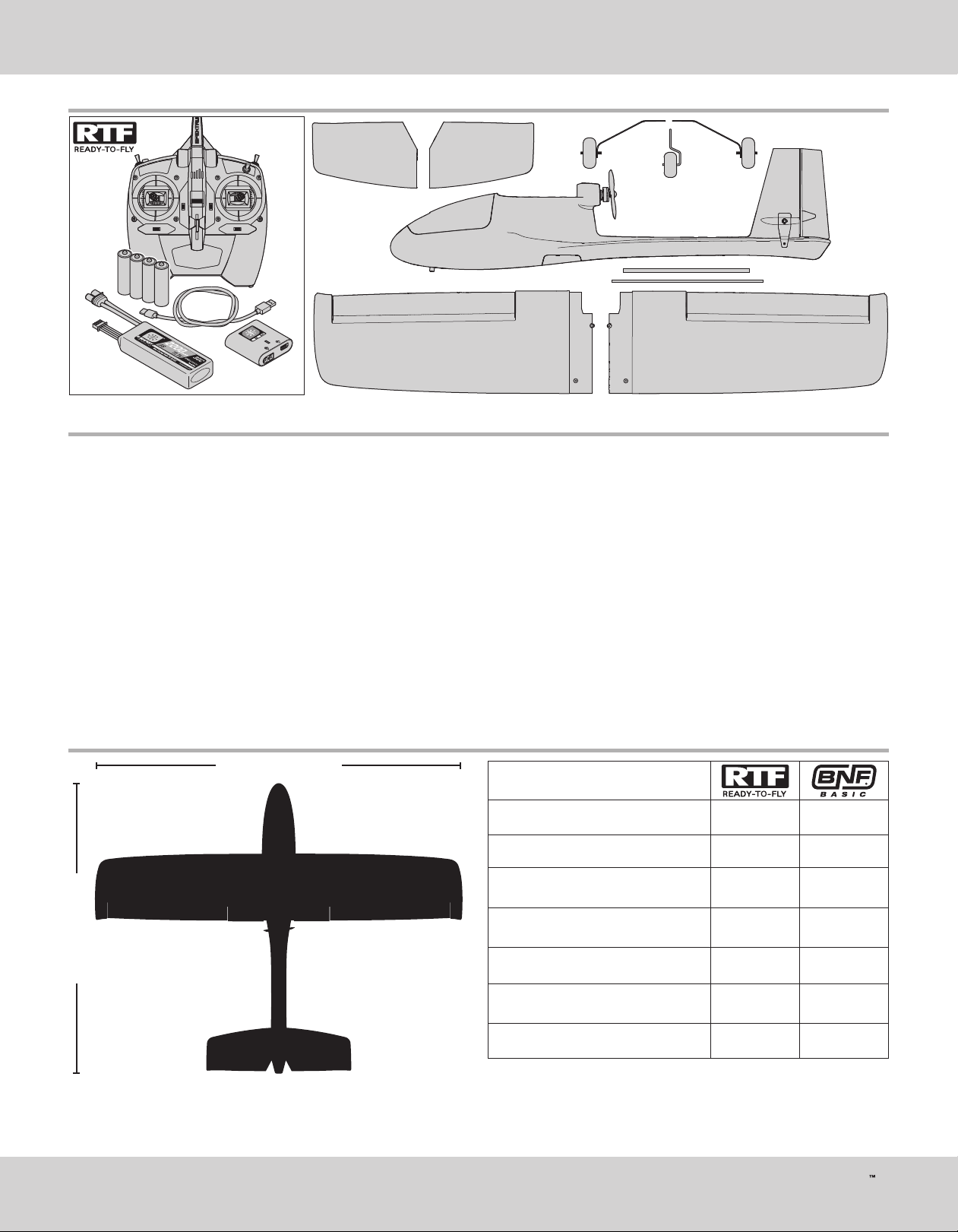
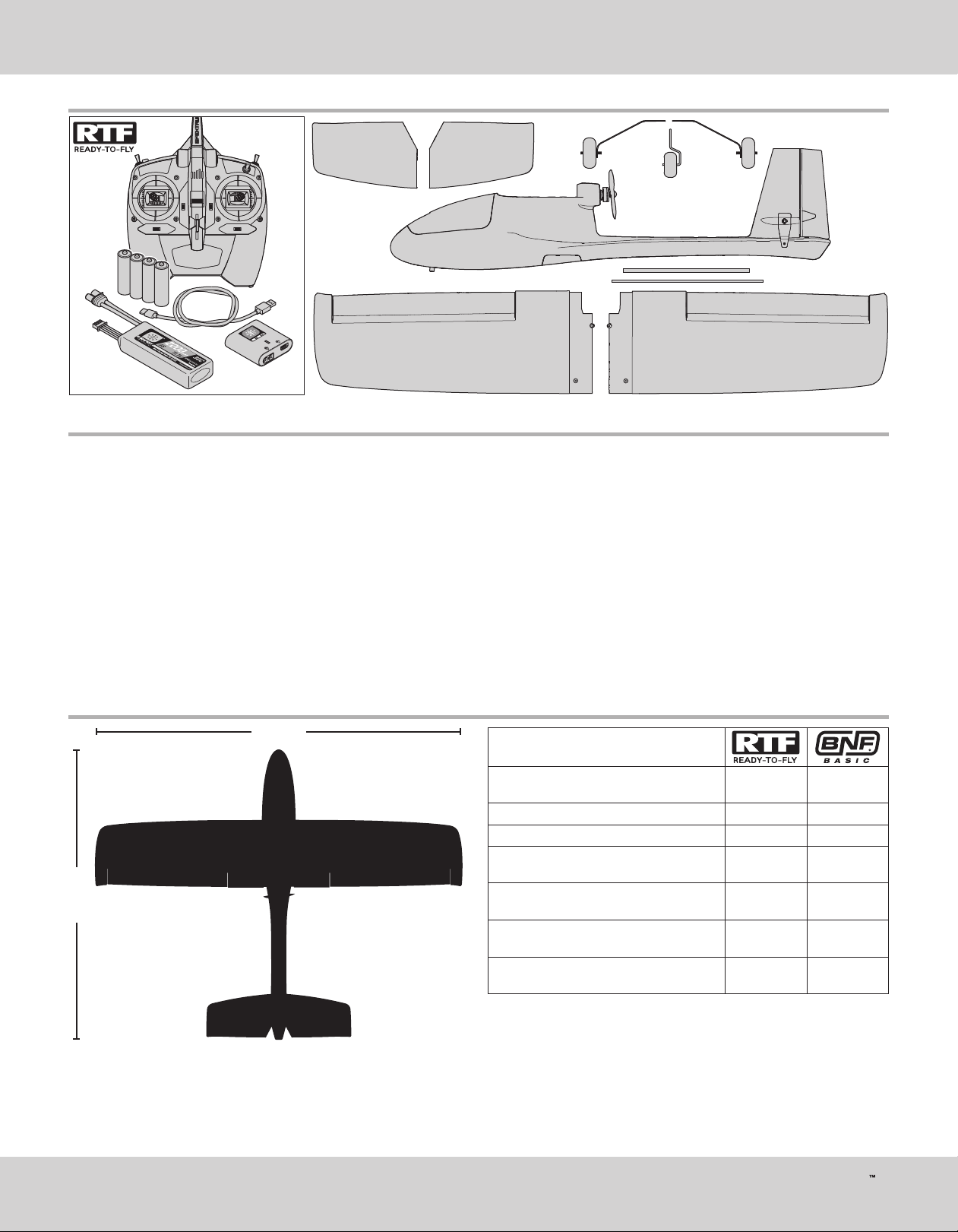
Box Contents
Table of Contents
EN
Specifi cations ................................................................................................. 3
Charging Warnings.......................................................................................... 4
Charge the Flight Battery ................................................................................4
Transmitter Setup ...........................................................................................5
Included DXe Transmitter (RTF Version) ........................................................... 6
Assemble the Aircraft ...................................................................................... 7
Transmitter and Receiver Binding .................................................................... 9
Install the Flight Battery .................................................................................. 9
Center of Gravity (CG) ................................................................................... 10
Control Direction Test .................................................................................... 10
Choose a Flying Field ....................................................................................11
Range Test .................................................................................................... 11
Install the Propeller .......................................................................................12
Sensor Assisted Flight Envelope (SAFE) Technology Flight Modes .................. 12
Flight Control ............................................................................................... 13
Prefl ight Checklist ......................................................................................... 14
Specifi cations
43.125 inch (1095mm)
Flying ........................................................................................................... 14
Trimming the Aircraft .................................................................................... 15
Post Flight Checklist ..................................................................................... 16
Factory Settings for the Control Horns and Servo Arms ................................. 16
Service and Repairs ......................................................................................16
®
AS3X
System Trouble Shooting Guide .......................................................... 17
Trouble Shooting Guide ................................................................................. 17
Replacement Parts List ................................................................................. 18
Optional Parts List ......................................................................................... 18
Limited Warranty .......................................................................................... 18
Contact Information ......................................................................................19
FCC Information ............................................................................................ 19
IC Information ............................................................................................... 20
Compliance Information for the European Union ............................................ 20
AMA National Model Aircraft Safety Code ...................................................... 21
Motor: 2306-2250 Brushless outrunner
(HBZ3809)
ESC: 30A (HBZ3808) Installed Installed
Servos: 8g Servo (SPMSS390) Installed Installed
Installed Installed
34.25 inch (867mm)
27.8-29.5oz
(788-836 g)
Receiver: AR636 6 channel AS3X
Receiver (SPMAR636
Battery: SMART 2200mAh 3S 11.1V 30C
™
LiPo; IC3
Battery Charger: S120 USB-C SMART
Charger, 1x20W (SPMXC1020)
Transmitter: Spektrum
range DSMX
(SPMX22003S30)
™
®
technology
DXe with full
3
®
Sport
Installed Installed
Included
Included
Included
Required to
Complete
Required to
Complete
Required to
Complete
AeroScout S
Page 4
EN
Charging Warnings
CAUTION: All instructions and warnings must be followed exactly.
Mishandling of Li-Po batteries can result in a fi re, personal injury, and/
or property damage.
• NEVER LEAVE CHARGING BATTERIES UNATTENDED.
• NEVER CHARGE BATTERIES OVERNIGHT.
• By handling, charging or using the included Li-Po battery, you assume all
risks associated with lithium batteries.
• If at any time the battery begins to balloon or swell, discontinue use
immediately. If charging or discharging, discontinue and disconnect.
Continuing to use, charge or discharge a battery that is ballooning or
swelling can result in fi re.
• Always store the battery at room temperature in a dry area for best results.
• Always transport or temporarily store the battery in a temperature range
of 40–120º F (5–49º C). Do not store battery or aircraft in a car or direct
sunlight. If stored in a hot car, the battery can be damaged or even catch fi re.
• Always charge batteries away from fl ammable materials.
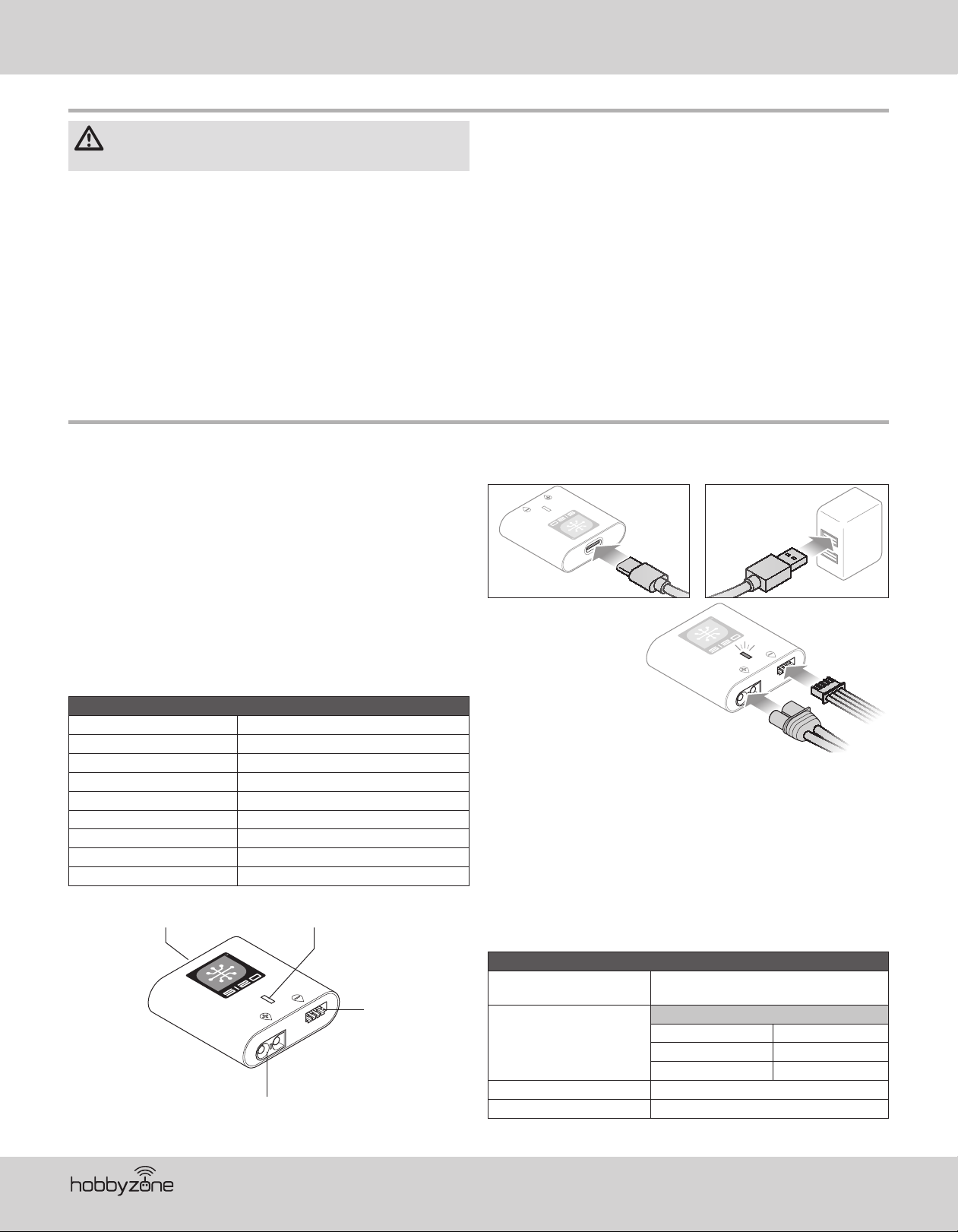
Charge the Flight Battery
The recommended battery for the HobbyZone® AeroScout™ S aircraft, included
with the RTF version, is an 11.1V, 2200mAh 3S 30C Smart Technology LiPo
battery with an IC3
battery should be of similar capacity, dimensions and weight to fi t in the fuselage.
The aircraft electronic speed control is equipped with an IC3 device connector.
Ensure the battery chosen is compatible. Always ensure the model balances at
the recommended center of gravity (CG) with the chosen battery. Follow your
chosen battery and battery charger instructions to charge the fl ight battery.
RTF Smart Technology Battery and S120 Charger,
Specifi cations and Operation
The Spektrum S120 SMART Technology battery charger included with the RTF
version of the aircraft is compatible only with Spektrum SMART 2-3 cell LiPo
batteries or 6-7 cell NiMH batteries. It is not compaptible with any other battery
chemistries or non-SMART batteries.
A USB power supply is required for use. A USB-C QC type power supply is
recommended for the fastest charge times.
Compatible USB Power Adaptor 5V/1A, 5V/2A, USB Quick Charge (QC) 2.0/3.0
™
connector (SPMX22003S30). If using a different battery, the
S120 Specifi cations
Input USB Type C, power supply not included
Input Voltage 5V-12V
Charge Power 18W max (dependant on power supply)
™
Battery Connector IC3
Battery Types LiPo, NiMH (Spektrum SMART Batteries only)
Cell Count 2-3 cell LiPo, 6-7 cell NiMH
Max Output Voltage 13.05V
Max Output Current Up to 2A
USB-C port LED Indicator
and balance connector
Balance Port
IC3 Charge Port
• Always inspect the battery before charging and never charge dead or
damaged batteries.
• Always disconnect the battery after charging, and let the charger cool
between charges.
• Always constantly monitor the temperature of the battery pack while charging.
• ONLY USE A CHARGER SPECIFICALLY DESIGNED TO CHARGE LI-PO
BATTERIES. Failure to charge the battery with a compatible charger may
cause fi re resulting in personal injury and/or property damage.
• Never discharge Li-Po cells to below 3V under load.
• Never cover warning labels with hook and loop strips.
• Never charge batteries outside recommended levels.
• Never attempt to dismantle or alter the charger.
• Never allow minors under the age of 14 to charge battery packs.
• Never charge batteries in extremely hot or cold places (recommended
between 40–120° F or 5–49° C) or place in direct sunlight.
To charge the included fl ight battery:
1. Using the supplied Type-C USB cable, connect the S120 charger to a USB
power supply (not included ).
2. Insert the Spektrum
SMART Battery IC3
connector (A) into the
charger IC3 port, and
insert the battery balance
lead (B) into the charger
balance port. Both the IC3
and balance connectors
must be connected for the
charging process to begin.
The battery may be disconnected from the charger at any time
to stop the charging process.
IMPORTANT: SMART NiMH batteries do not have a balance connector.
3. Disconnect the IC3 and balance connectors when the charge and balance
cycles are complete, as indicated by the LED.
4. The LED indicator will glow solid red to indicate a charging error. Follow
the operation steps to ensure proper connection is used to charge the
battery.
Refer to the LED indicator table for charger status.
IMPORTANT: Connecting a non-SMART battery will cause a charge error and
Power On
LiPo: Purple LED
NiMH: Yellow LED
Charge Complete Green LED (Solid)
Error Red LED (Solid)
the S120 will not recognize or charge the battery.
LED Indicator
USB 5V: White LED
USB Quick Charge 2.0/3.0: Blue LED
Less Than 25% Single Flash
25% – 75% Double Flash
76% – 99% Triple Flash
A
Battery Capacity
B
®
4
Page 5
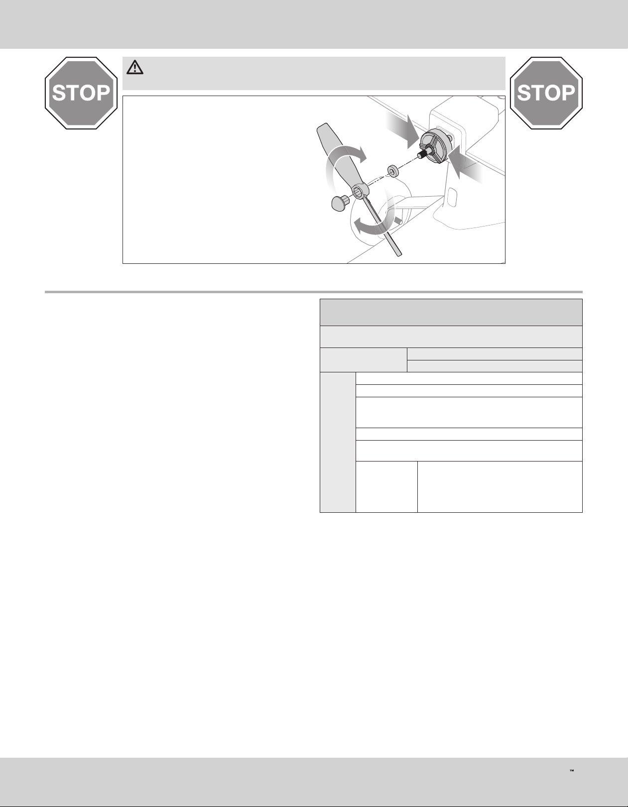
WARNING: Before proceeding further, remove the propeller and spinner from the motor shaft. Never attempt
to program the radio components, assemble the aircraft or perform maintenance of any kind without
removing the propeller. Serious injury could result if the motor starts inadvertently with the propeller still attached.
1. Ensure the fl ight battery is NOT connected to the aircraft.
2. Hold the motor can fi rmly to keep it from rotating.
3. Twist the propeller and prop nut clockwise to
loosen them from the motor shaft.
4. Remove the propeller, prop nut and prop washer.
Transmitter Setup
EN
If using any DSMX transmitter other than the included DXe (3 position gear
switch, RTF only) the radio will have to be confi gured correctly for the SAFE
system to work properly.
• SAFE Flight mode is selected using Channel 5 signal (high, middle, low)
• Panic mode is selected with Channel 6 signal (high, low)
Refer to your transmitter’s manual for more information about transmitter setup.
If using a 2 position switch for SAFE fl ight modes, only Beginner and
Experienced modes will be active.
Any DXe Transmitter that was not included with a HBZ AeroScout RTF will need
to be programmed using the Spektrum Programmer (SPMA3065) to function
correctly with this aircaft. Visit www.spektrumrc.com to download the correct
program for this aircraft.
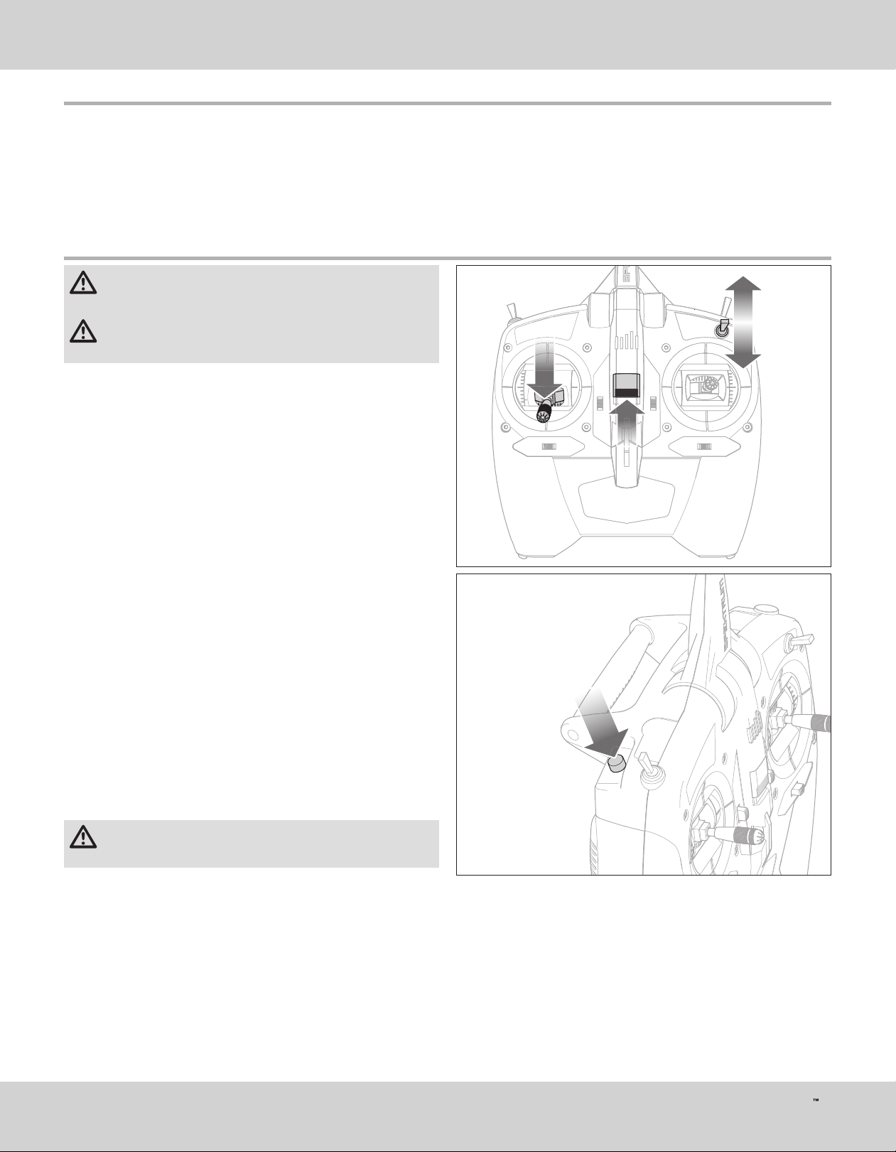
Computerized Transmitter Setup
(DX6 Gen2, DX6e,DX7 Gen2, DX8 Gen2, DX9, iX12, DX18 and DX20)
Start all transmitter programming with a blank model
(do a model reset), then name the model.
Set Aileron, Elevator, and
Rudder Rates to:
Go to the SYSTEM SETUP
Set MODEL TYPE: AIRPLANE
Go to CHANNEL ASSIGN:
DX6
DX6e
DX8
DX9
iX12
DX20
click NEXT to go to Channel Input Confi g:
GEAR: B, AUX1: I
Go to the FUNCTION LIST
Go to Throttle Cut:
set to Switch H, Position: –130
Resulting in:
HIGH 100%
LOW 70%
Switch H operates Throttle Cut, position 0 is
normal and position 1 cuts power to the throttle.
Switch B operates the 3 SAFE Plus modes
(0 beginner/1 intermediate/2 experienced).
Button I operates PANIC mode.
5
AeroScout S
Page 6
EN
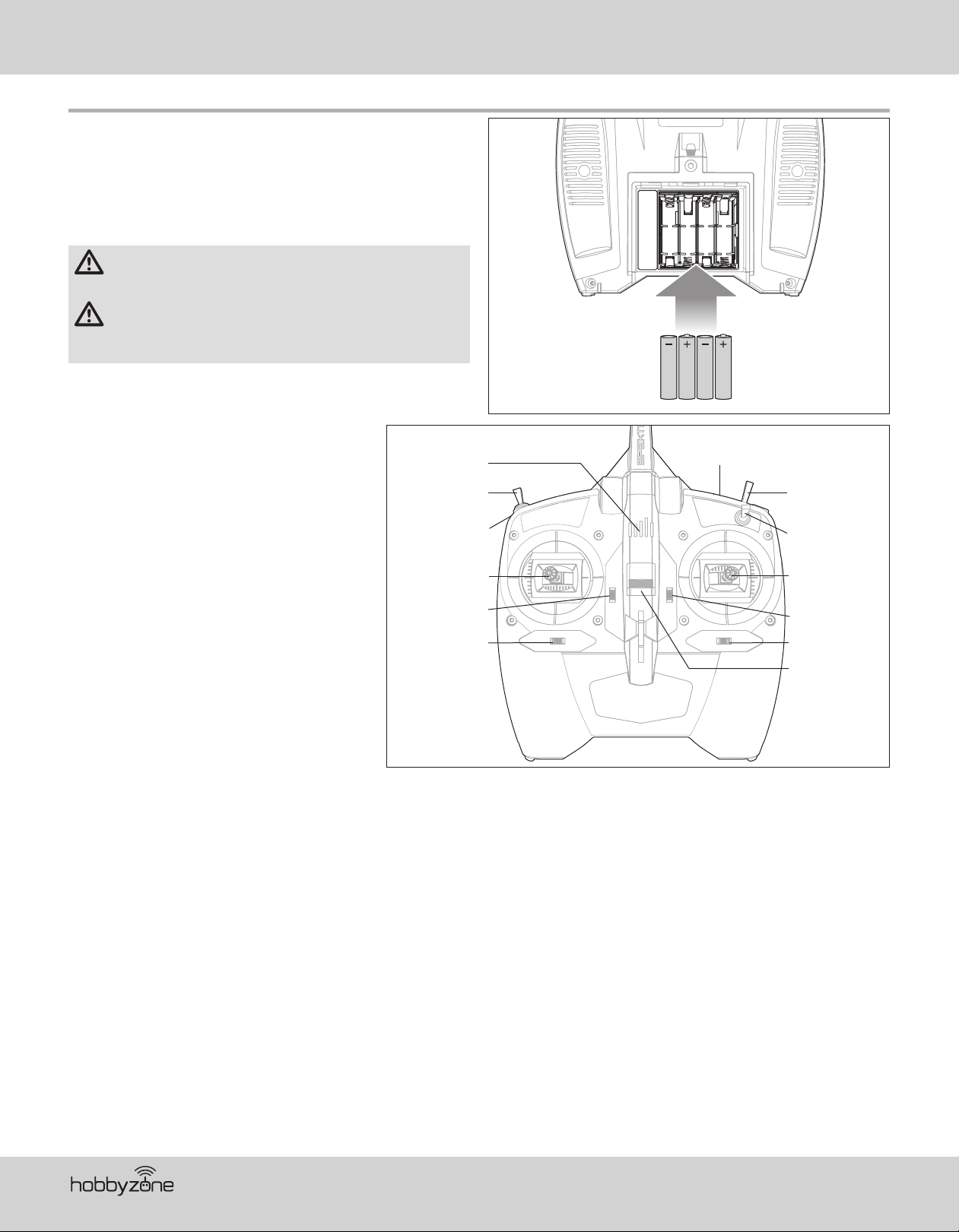
Included DXe Transmitter (RTF Version)
Installing the Transmitter Batteries
Remove the battery cover, install the four included batteries (noting proper
polarity) and reinstall the battery cover.
Low Battery Alarm
The LED indicator fl ashes and the transmitter beeps progressively faster as the
battery voltage drops.
Replace the transmitter batteries when the transmitter begins to beep.
CAUTION: If using rechargeable batteries, charge only rechargeable
batteries. Charging non-rechargeable batteries may cause the
batteries to burst, resulting in injury to persons and/or damage to property.
WARNING: Do not pick up the transmitter by the antenna. Do not alter
or put weight on the antenna. Damage to antenna parts can decrease
transmitter signal strength, which can result in loss of model control, injury
or property damage.
RTF Transmitter Control Layout
The diagram shows the control layout of the included
DXe transmitter.
LED Indicator
SAFE Plus Mode
Switch
Bind/PANIC
Button
Throttle/Rudder
Throttle Trim
Rudder Trim
Wireless Trainer
Bind Button
Throttle Cut
Switch
Hi / Low Rate
Switch
Elevator/Aileron
Stick
Elevator Trim
Aileron Trim
Power Switch
®
6
Page 7
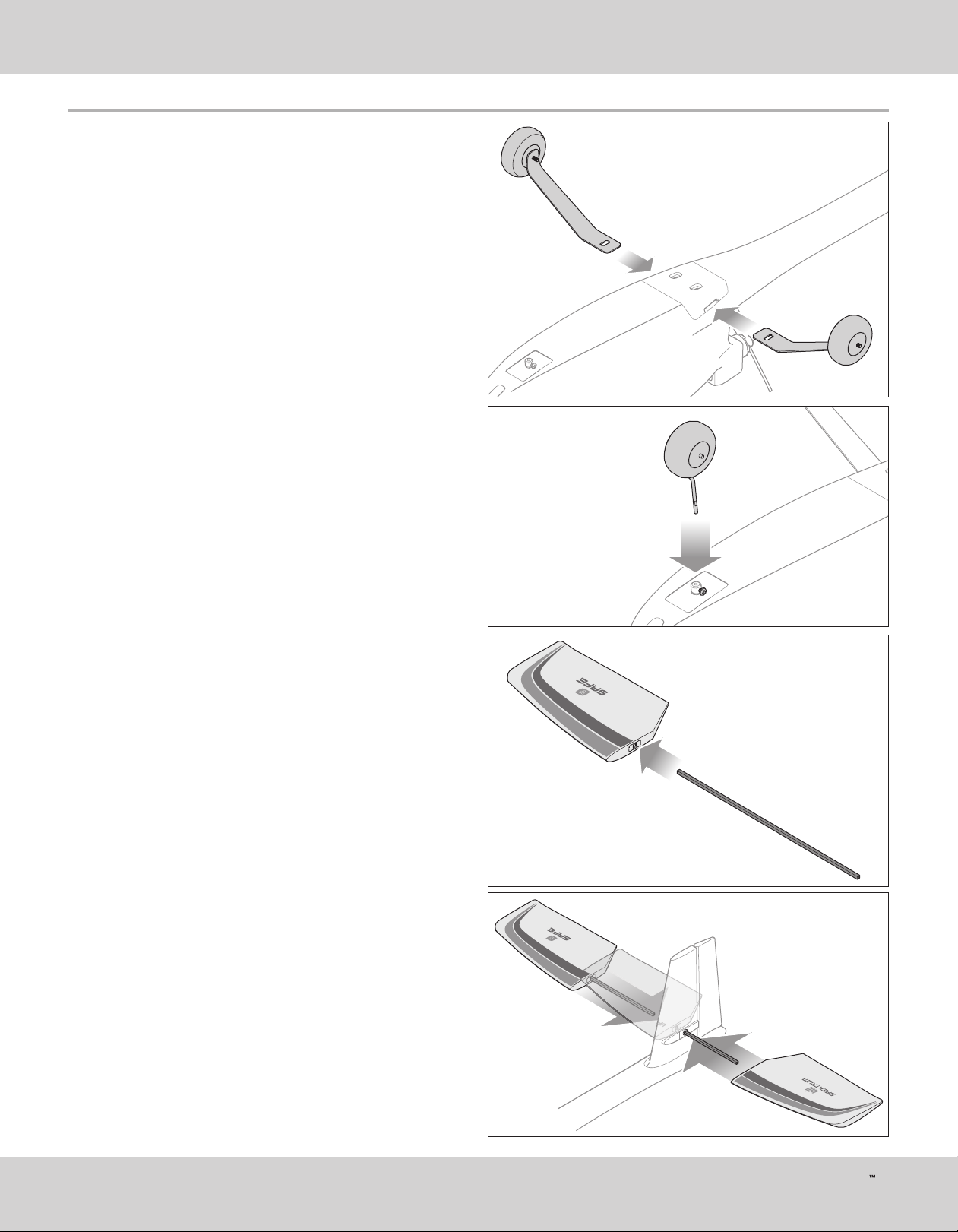
Assemble the Aircraft
Install the landing gear
1. Slide the main gear into the slots in the fuselage until they lock into place.
2. Insert the nose gear into the wheel collar as shown and tighten the
setscrew against the fl at in the gear wire using a phillips screwdriver.
EN
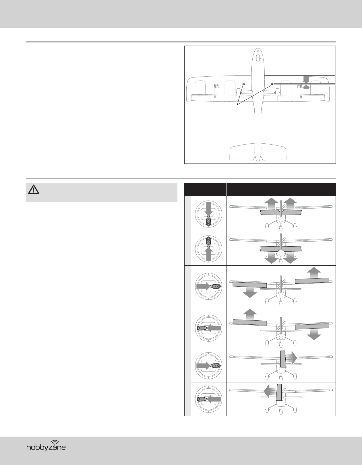
Install the horizontal tail
1. Slide the longer of the two included square carbon fi ber tubes fully into the
hole of either of the horizontal stabilizers. The tube is a compression fi t and
does not require any adhesive.
2. Insert the tube through the hole in the vertical tail of the fuselage as shown,
until the previously attached horizontal stabilizer is against the fuselage.
IMPORTANT: The decals on the horizontal stabilizers must face up when the
stabilizers are installed correctly.
3. Slide the opposite horizontal stabilizer over the other end of the tube. Press
the stabilizer halves together until they are both fully seated on the tube
and there is just a small gap between the stabilizers and the fuselage.
7
AeroScout S
Page 8
EN
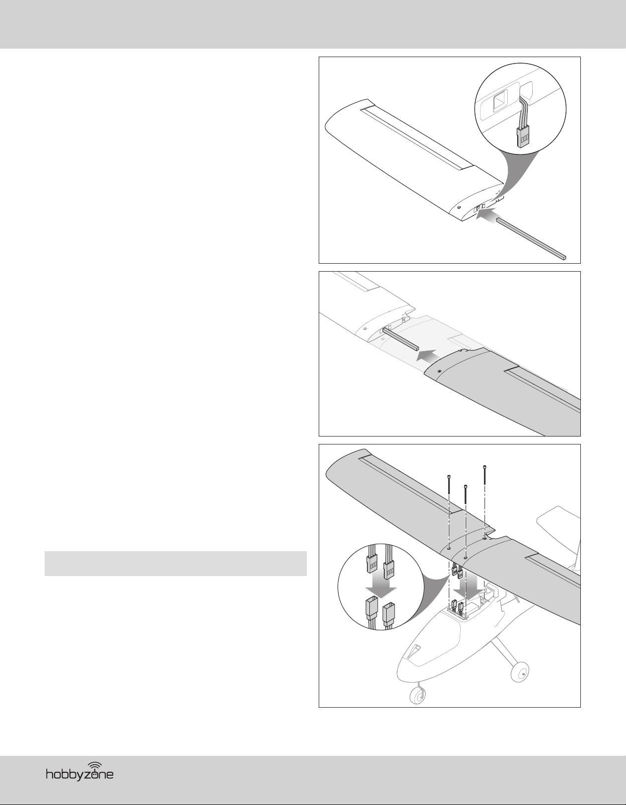
Assemble and install the wing
1. Slide the carbon fi ber wing spar fully into a wing panel as shown. Ensure
the aileron servo lead exits through the slot in the bottom of the wing.
2. Slide the opposite wing panel over the wing spar until the root of the wing
panels are tight and the rear mounting hole is correctly aligned. Ensure
both aileron servo leads exit through the bottom of the wing and are not
pinched between the wing panels.
3. Connect the aileron servo leads to the y-harness installed in channel 2 of
the receiver.
4. Center the wing on the fuselage. Ensure the aileron leads are not pinched
between the wing and fuselage.
5. Attach the wing with the included 50mm screws. Do not overtighten the
wing screws, as it may damage the wing or the attachment points in the
fuselage.
IMPORTANT: The wing screws may be a tight fi t the fi rst few times they are
installed into the fuselage. Use a screwdriver if necessary until the fuselage
attachment points loosen up enough for the screws to be installed by hand.
NOTICE: Do not overtighten the wing screws. Doing so will crush the foam of
the wing or damage the fuselage attachment points.
®
8
Page 9
Transmitter and Receiver Binding
EN
CAUTION: Connecting the battery to the ESC with reversed polarity
will cause damage to the ESC, the battery or both. Damage caused by
incorrectly connecting the battery is not covered under warranty.
An extension is installed in the receiver bind port so binding may be done
through the battery hatch at the front of the aircraft without having to remove
the wing assembly. Simply insert the bind plug in the open end of the extension
to enter bind mode.
The transmitter included with the RTF model is bound to the aircraft at the factory. If
you need to re-bind for any reason, follow the binding procedure as shown.
The BNF version of this aircraft requires a Spektrum
equipped aircraft transmitter for proper operation.
Refer to your transmitter instructions for binding to a receiver.
If you encounter problems after following the binding instructions, contact the
appropriate Horizon Product Support offi ce.
™
DSM2®/DSMX® technology
Binding Procedure
1. Make sure the transmitter is powered off.
2. Make sure the transmitter controls are neutral, the throttle is at the lowest
position*, the throttle trim is centered and the aircraft is immobile.
3. Install a bind plug in the receiver bind port extension.
4. Connect the fl ight battery to the ESC. The ESC will produce three
ascending tones and the receiver LED will begin to fl ash rapidly.
5. Refer to your transmitter manual for specifi c instructions to place the
transmitter in bind mode.
6. When the receiver binds to the transmitter, the receiver LED will glow
solid and the aircraft will begin the initialization process, indicated by the
control surfaces cycling.
7. Remove the bind plug from the bind port extension and store in a safe
place. The receiver should retain the binding instructions received from
the transmitter until another binding is done.
* The throttle will not arm if the transmitter’s throttle stick is not set to the
lowest position.
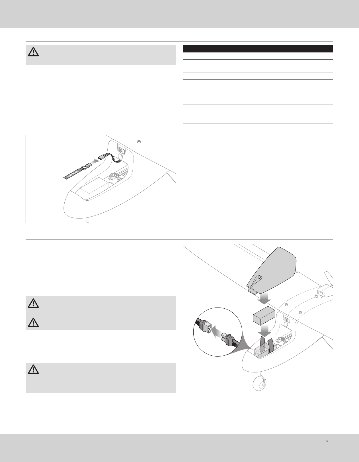
Install the Flight Battery
1. Power on the transmitter.
2. Set the transmitter MOTOR switch to “DISARM”.
3. Lift at the rear of the battery hatch to remove it from the fuselage.
4. Attach a piece of adhesive-back loop material to the bottom of the battery.
5. Place the battery, loop material down, on the battery tray. The placement of
the battery can be adjusted forward or backward to help balance the aircraft.
6. When the battery is properly placed, secure it with the hook and loop strap.
7. Connect the IC3 battery connector to the ESC, noting proper polarity.
CAUTION: Connecting the battery to the ESC with reversed polarity
will cause damage to the ESC, the battery or both. Damage caused by
incorrectly connecting the battery is not covered under warranty.
CAUTION: Always keep hands away from the propeller. When armed,
the motor will turn the propeller in response to any throttle movement.
8. Place the aircraft on a fl at, level surface. The control surfaces will cycle as
the SAFE system initializes. Initialization is complete when the surfaces
stop moving.
9. Replace the battery hatch on the fuselage by fi rst inserting the front tab
then lowering the back until the magnet catches.
CAUTION: Always disconnect the Li-Po fl ight battery from the aircraft
when not fl ying to avoid over-discharging the battery. Batteries
discharged to a voltage lower than the lowest approved voltage may become
damaged, resulting in loss of performance and potential fi re when batteries
are charged.
9
AeroScout S
Page 10
EN
Center of Gravity (CG)
An aircraft with the correct CG has its weight balanced on the center of the
aircraft for safe, stable fl ight.The aircraft CG and weight are based on having
the recommended battery installed.
The CG location is 67-70mm back from the leading edge of the wing at the
root and is marked on the bottom of the wing with a raised “CG”. Balance the
aircraft on your fi ngertips at the raised marks.
Adjust the battery position as needed get the aircraft to balance correctly.
• If the nose goes down, move the fl ight battery back until the aircraft balances.
• If the nose goes up, move the fl ight battery forward until the aircraft balances.
When in intermediate and experienced modes, if the aircraft CG is too far
forward (nose heavy), up elevator is required to fl y level at 50%-60% power. If
the aircraft CG is too far aft (tail heavy), down elevator is required to fl y level. In
Beginner mode the aircraft is not affected. The SAFE Plus system controls the
aircraft attitude.
Control Direction Test
CG Marks 67-70mm
from the leading edge
WARNING: Do not perform this or any other equipment test with the
propeller installed on the aircraft. Serious injury or property damage
could result from the motor starting inadvertently.
1. Set the fl ight mode switch to Experienced mode (position 2).
2. Keep the throttle at zero and place the model on level ground away from
obstacles.
3. Move the sticks on the transmitter as described in the table to ensure the
aircraft control surfaces respond as shown.
If the control surfaces do not respond as shown, DO NOT FLY. Refer to the
Troubleshooting Guide for more information. If you need more assistance,
contact the appropriate Horizon Hobby Product Support department.
If the aircraft responds as shown, continue on to the Flight Control section.
Transmitter
command
ElevatorAileronRudder
Control Surface
Response
®
10
Page 11
Choose a Flying Field
Consult local laws and ordinances before choosing a location to fl y your aircraft.
In order to have the most success and to protect your property and aircraft, it is
very important to select a place to fl y that is very open.
Remember, your aircraft can reach signifi cant speeds when fl ying and can
cover ground quickly. Plan on fl ying in an area that gives you more space than
you think you need, especially with fi rst fl ights.
The fl ying site should:
• Have a minimum of approximately 1300 feet (400m) of clear space in all
• Be clear of people and pets.
• Be free of trees, buildings, cars, power lines or anything that could entangle
Range Test
WARNING: Do not perform this or any other equipment test with the
propeller installed on the aircraft. Serious injury or property damage
could result from the motor starting inadvertently.
WARNING: While holding the aircraft during the range test, always
keep body parts and loose items away from the motor. Failure to do
so could cause personal injury.
Before each fl ying session, and especially with a new model, you should
perform a range check. If you have the BNF aircraft, refer to your transmitter
manual to perform a range check of your system.
The RTF included DXe transmitter incorporates a range check mode to reduce
the output power of the transmitter. Follow the directions below to enter range
check mode for the DXe transmitter:
1. Power on the transmitter for 5 seconds or more with the throttle stick and
trim low. Plug in the aircraft battery and keep the aircraft immobile for
5seconds.
2. Face the model with the transmitter in your normal fl ying position.
3. Toggle the HI/LO Rate switch rapidly 4 times and then press and hold the
bind button. The transmitter LEDs will fl ash and the alarm will sound. The
system is in range check mode. Do not let go of the bind button until you
are fi nished with the range check.
IMPORTANT: You must hold the BIND/Panic button during the entire range
check process. Releasing the button will exit the range check mode.
4. With the radio system powered on and the model restrained on the ground,
stand 28meters (90 feet) away from the model.
TIP: In some aircraft, when the model is placed on the ground, the antenna(s)
can be within inches of the ground. Close proximity of the antenna(s) to the
ground can reduce the effectiveness of the range check. If you experience
issues during the range check, restrain the model on a non-conductive stand
or table up to 2ft (60cm) above the ground, then range check the system again.
5. Move the transmitter rudder, elevator, aileron and throttle controls to ensure
they operate smoothly at 28 meters (90 feet).
6. If control issues exist, do not attempt to fl y. Refer to the contact table at the
end of the this manual to contact Horizon Hobby product support. Also, see
the Spektrum website for more information.
7. When the range check is successfully completed, release the bind button to
exit range check mode.
CAUTION: Due to reduced output power of the transmitter,
NEVER attempt to fl y while the transmitter is in range check mode.
Loss of control will occur.
EN
directions.
your aircraft or interfere with your line of sight.
4X
HOLD
11
AeroScout S
Page 12
EN
Install the Propeller
WARNING: Do not install the propeller until the aircraft has been
completely assembled, all systems have been checked thoroughly
and you are located at a suitable fl ying site.
Follow the instructions below to install the propeller and spinner:
1. Place the prop washer on the motor shaft.
2. Insert the prop nut in the propeller. The raised letters on the propeller should
face away from the rounded head of the prop nut. When the propeller is
installed, the raised letters should face toward the front of the aircraft.
3. Grip the motor can fi rmly to keep it from rotating.
4. Thread the propeller and prop nut onto the motor shaft.
IMPORTANT: The motor shaft and prop nut are reverse-threaded. Turn the prop
nut counter-clockwise to tighten it to the motor shaft.
5. Tighten propeller and prop nut to the motor shaft by hand.
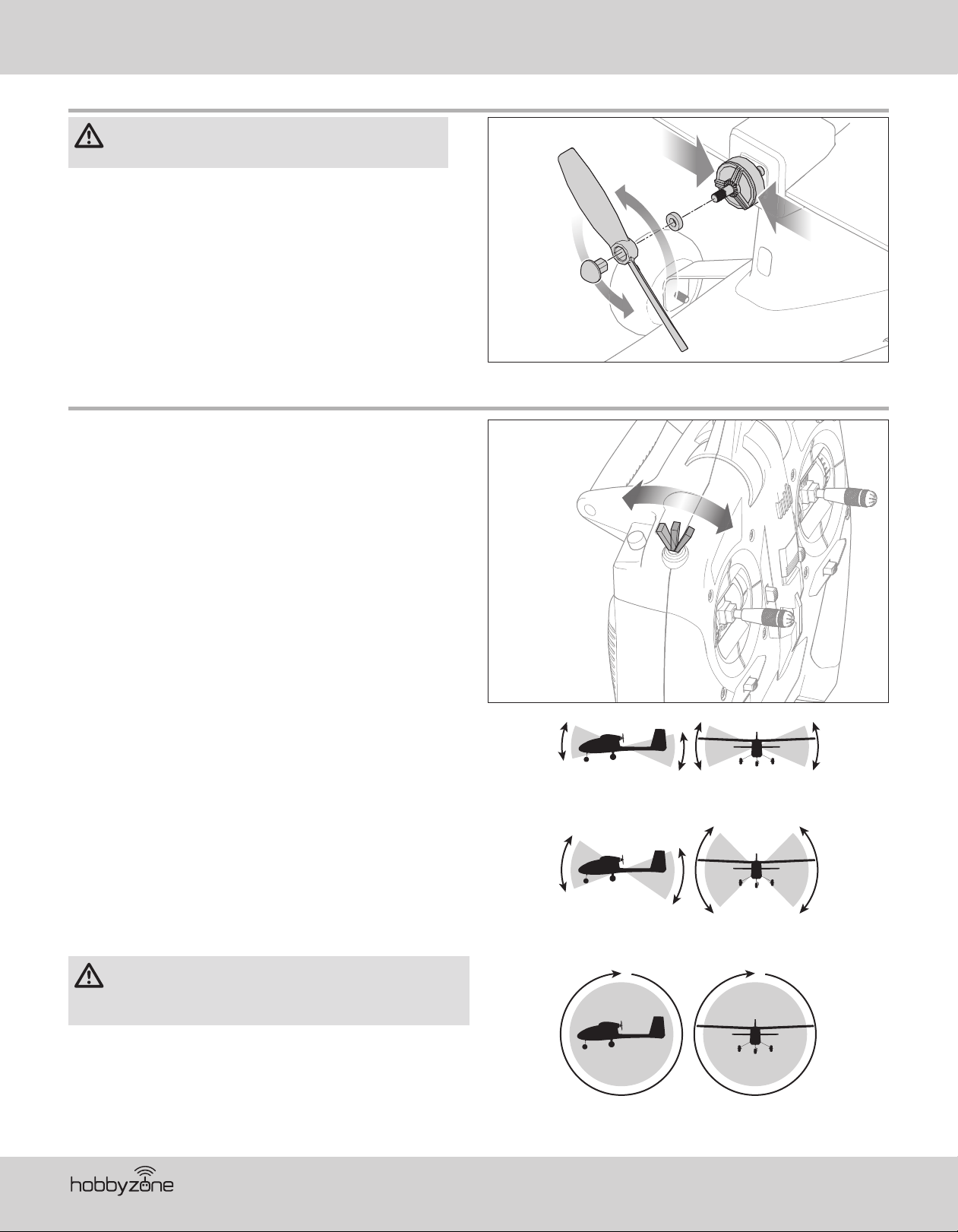
Sensor Assisted Flight Envelope (SAFE) Technology Flight Modes
At any time during a fl ight you can switch between the 3fl ight modes or use
Panic recovery to get your aircraft to a safe fl ying attitude. Change between
fl ight modes by changing the fl ight mode switch position.
Beginner Mode (position 0)
• Envelope limit: Pitch (nose up and down) and Roll (wing tips up and down)
angles are limited to help you keep the aircraft airborne.
• Self-leveling: when the pitch and roll controls are returned to neutral, the
aircraft returns to level fl ight.
• Stability assisted takeoff and landing.
• Throttle based climb and descent.
Intermediate Mode (position 1)
• Natural Flight Experience: In normal training fl ight conditions, the pilot
experiences natural AS3X
precision.
• Large Flight Envelope: The pilot is only prevented from entering extreme
fl ight conditions outside the training fl ight envelope.
®
fl ight for smooth handling and outstanding
Experienced Mode (position 2)
• Natural Flight Experience: The pilot experiences natural AS3X fl ight for
smooth handling and outstanding precision.
• Unlimited Flight Envelope: No limit on Pitch and Roll angles (airframe limited).
Panic Recovery
This function is intended to provide you with the confi dence to continue to
improve your fl ight skills. If you become disoriented or the aircraft is in an
unknown or uncomfrotable attitude:
1. Press and hold the Bind/PANIC button on the transmitter and release the
control sticks. The aircraft will immediately pull out of a dive and roll wings
upright and level.
IMPORTANT: The aircraft will recover to a safer attitude even if sticks are held
while holding the PANIC button. However, release the control sticks for the
quickest recovery.
2. Release the PANIC button and continue a gentle climb to a safe altitude.
CAUTION: The Panic Recovery function will not avoid obstacles in the
aircraft fl ight path. Suffi cient altitude is required for the aircraft to
return to straight and level fl ight if the aircraft is upside down when the panic
function is applied.
1
0
Beginner Mode
(Switch Position 0)
Intermediate Mode
(Switch Position 1)
2
RollPitch
RollPitch
RollPitch
Experienced Mode
(Switch Position 2)
®
12
Page 13
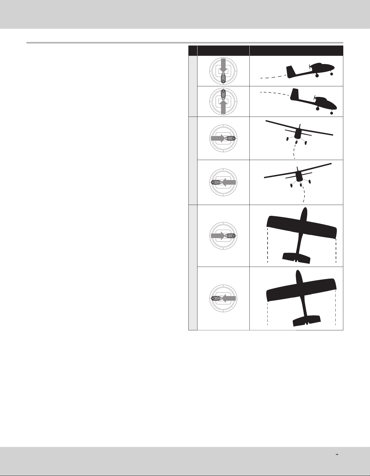
Flight Control
EN
IMPORTANT: Even though SAFE technology is a very helpful tool, the aircraft
still needs to be fl own manually. If incorrect input is given at lower altitudes
or at slower speeds, the aircraft can crash. Study these control inputs and the
aircraft response to each carefully before attempting your fi rst fl ight.
For fi rst fl ights, set the SAFE® fl ight mode switch to Beginner Mode (position0).
For smooth control of your aircraft, always make small corrections. All
directions are described as if you were sitting in the aircraft.
Flying faster or slower: When your aircraft is stable in the air, push the
throttle stick up to make the aircraft go faster. Pull the throttle stick back to
slow down. The aircraft will climb when the throttle is increased.
Elevator up and down: Push the elevator stick forward to make the aircraft
go down. Pull the elevator stick back to go up.
Aileron right and left: Move the aileron stick right to make the aircraft roll or
“bank” right. Move the aileron stick left to bank left.
TIP: Always picture yourself in the aircraft when determining which way to
bank the aircraft wings. When the aircraft is fl ying away from you, banking
the aircraft right or left appears normal. When fl ying toward you, the aircraft
will appear to bank the opposite direction to the control input given. This will
become more instinctual with experience.
Rudder left and right: Push the rudder stick left or right to yaw or point the
nose of the aircraft left or right. The rudder stick is also used to steer the
aircraft left and right while taxiing on the ground.
TIP: Similar to aileron control, picture yourself in the aircraft to determine
which direction to point the nose whether you are fl ying away from yourself or
toward yourself.
Transmitter command Aircraft Response
ElevatorAileronRudder
13
AeroScout S
Page 14
EN
Prefl ight Checklist
1. Find a safe and open fl ying area
2. Charge fl ight battery
3. Install fully charged fl ight battery in aircraft
4. Make sure linkages move freely
5. Perform control direction test
Flying
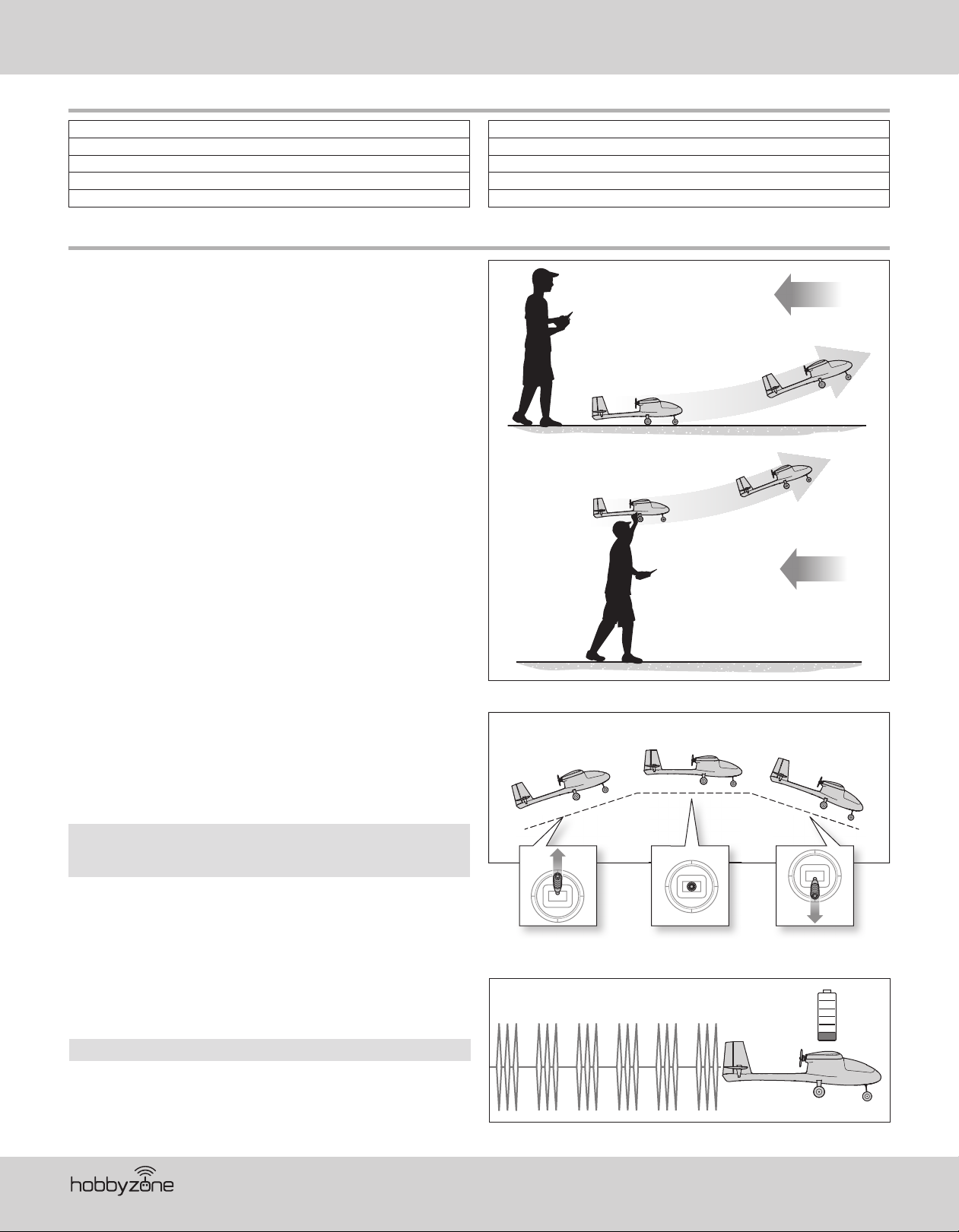
Takeoff
Set the fl ight mode switch to Beginner Mode (position 0) for your fi rst fl ights.
Set a fl ight timer for 5-6 minutes.
Ground Launch
Once the aircraft is ready for fl ight, slowly advance the throttle to start the
takeoff roll into the wind. Small rudder inputs may be required for heading
correction as the aircraft will begin a slow climb out as the throttle is
advanced.
Hand Launch
Once the aircraft is ready for fl ight, use the following steps.
1. Grip the aircraft under the fuselage, behind the main gear.
2. Slowly advance the throttle to 100%.
3. Throw the aircraft slightly nose up and directly into the wind. Small rudder
inputs may be required for heading correction as the aircraft will begin a
slow climb out as the throttle is advanced.
6. Perform a range check
7. Plan fl ight for fl ying fi eld conditions
8. Set a fl ight timer for 5-6 min.
9. Install the propeller
10. Have fun!
Slowly advance
the throttle stick.
Slowly advance
the throttle stick.
Wind
Wind
In Flight
Let the aircraft climb at full throttle, into the wind, until the aircraft gets about
300 feet (91m) above the ground, then decrease the throttle to half (50%).
Make small and gentle stick movements to see how the aircraft responds.
Flying with the nose pointed toward you is one of the hardest things to do
when learning to fl y. Practice fl ying in large circles high off the ground.
If you lose orientation of the aircraft, press and hold the PANIC button and the
aircraft will return to level fl ight.
NOTICE: If a crash is imminent, activate throttle hold or quickly lower the
throttle and throttle trim. Failure to do so could result in extra damage to the
airframe, as well as damage to the ESC and motor.
Low Voltage Cutoff (LVC)
LVC is a function built into your ESC to protect the battery from over-discharge.
When the battery charge is low, LVC limits power supplied to the motor. The
aircraft will begin to slow and you will hear the motor pulse. When the motor
power decreases, land the aircraft immediately and recharge the fl ight battery.
NOTICE: Repeated fl ying to LVC will damage the battery.
Disconnect and remove the Li-Po battery from the aircraft after use to prevent
trickle discharge. Charge your Li-Po battery to about half capacity before storage.
During storage, make sure the battery charge does not fall below 3V per cell.
When properly trimmed, the aircraft’s wing design causes a climb at full
throttle without the use of elevator.
50% throttleFull throttle Reduced throttle
®
14
Page 15
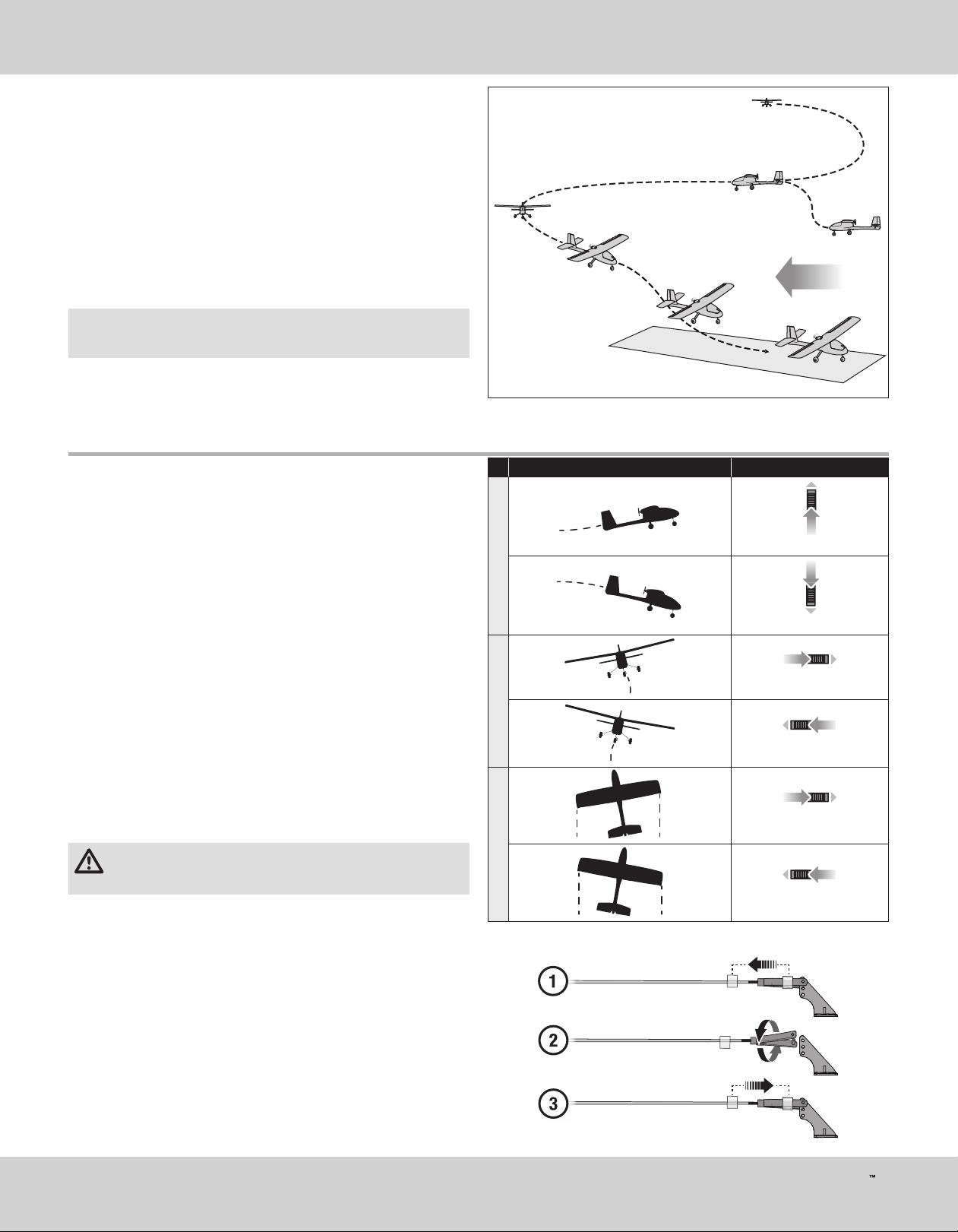
Landing
1. Reduce the throttle to around 50% to slow the airspeed.
2. Fly the aircraft downwind past the end of the runway.
3. Turn the aircraft into the wind and line the aircraft up with the runway
center line.
4. Decrease the throttle further and begin descending towards the runway,
keeping the wings level during approach. Try to have the aircraft at
approximately 10ft (3m) altitude as it passes over the threshold of the
runway.
5. As the aircraft passes over the threshold of the runway decrease the
throttle fully.
6. Just as the aircraft is about to touch down, gently pull back on the elevator
to raise the nose and fl air for a gentle landing.
NOTICE: If a crash is imminent, activate throttle hold or quickly lower the
throttle and throttle trim. Failure to do so could result in extra damage to the
airframe, as well as damage to the ESC and motor.
IMPORTANT: When fi nished fl ying, never keep the aircraft in the sun. Do not
store the aircraft in a hot, enclosed area such as a car. Doing so can damage
the foam.
Trimming the Aircraft
EN
Wind
10ft power is cut
Adjusting Trim in fl ight
If your aircraft does not fl y straight and level at half throttle with the sticks at
neutral, fl y into the wind and adjust the trim sliders as indicated in the table
until the aircraft maintains a reasonably straight and level fl ight path.
• Trimming is best done in calm wind conditions.
• The SAFE fl ight mode switch should be set to Experienced mode (position2)
before adjusting the trims.
After the aircraft is trimmed in fl ight, land the aircraft and proceed to the
Manually Adjusting Trim section to set the trim mechanically.
The included RTF DXe transmitter features electronic trim buttons. The
transmitter emits a faint beep with each click of the trim buttons in either
direction. Holding the button in either direction quickly adjusts the trim several
steps until the button is released or until the trim reaches the end of its travel.
If the trim button does not beep when clicked, the trim is at the far end of its
travel. Center trim is indicated by a slightly louder beep.
Manually Adjusting Trim
WARNING: Do not perform any maintenance with the propeller
installed on the aircraft. Serious injury or property damage could
result from the motor starting inadvertently.
The SAFE Plus fl ight mode switch should be set to Experienced mode
(position2) before manually adjusting the trim settings.
The aircraft should be kept still while perfoming manual adjustment of trim.
With the trim settings from the trim fl ight still set in the transmitter, take note of
the positions of each of the control surfaces, one at a time.
Adjust the clevis on each control surface to position the surface the same as it
was with the trim offset.
1. Remove the clevis from the control horn.
2. Turn the clevis (as shown) to lengthen or shorten the pushrod.
3. Close the clevis onto the control horn and slide the tube towards the horn to
secure the clevis.
4. Move to the next control surface.
When you have all of the surface trims centered, return the trim settings on
the transmitter to neutral by pushing the trim buttons for each surface until the
transmitter emits a loud beep indicating center trim.
Aircraft Drift Trim Required
Elevator Trim
Elevator
Elevator Trim
Aileron Trim
Aileron
Aileron Trim
Rudder Trim
Rudder
Rudder Trim
15
AeroScout S
Page 16
EN
Post Flight Checklist
1. Activate Throttle Cut.
2. While avoiding the area of the propeller and prop arc,
disconnect and remove the fl ight battery from the aircraft
3. Power off the transmitter
4. Recharge the fl ight battery
5. Inspect the airframe for loose or damaged parts
6. Repair or replace all damaged parts
7. Store fl ight battery apart from the aircraft and monitor the battery charge
8. Make note of fl ight conditions and fl ight plan results,
planning for future fl ights
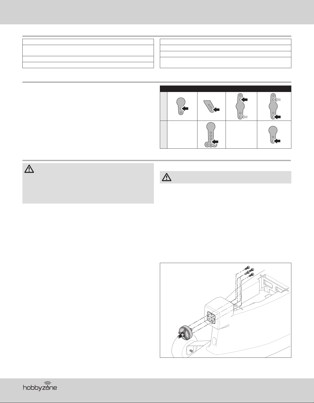
Factory Settings for the Control Horns and Servo Arms
The Illustration shows recommended hole settings in the servo arms and
control horns.
Elevator Ailerons Rudder Nose Wheel
Servo ArmsControl Horns
Service and Repairs
WARNING: Do not perform this or any other equipment maintenance
with the propeller installed on the aircraft. Serious injury or property
damage could result from the motor starting inadvertently.
NOTICE: Crash damage is not covered under warranty.
NOTICE: After any impact or replacement always ensure the receiver is
secure in the fuselage. If you replace the receiver, install the new receiver in
the same location and orientation as the original or damage may result.
Repairs to the foam can be made using virtually any adhesive
(hot glue, regular CA [cyanoacrylate adhesive], epoxy, etc).
Use of CA accelerator on the aircraft can damage paint. DO NOT handle the
aircraft until accelerator fully dries.
When damaged parts are not repairable, see the Replacement Parts list for
ordering by item number.
Service of Power Components
WARNING: Always disconnect the fl ight battery from the model
before removing the propeller.
Disassembly
1. Remove the wing from the aircraft.
2. Use a long 2.5mm hex driver inside the motor pod to remove the four
screws (A) from the motor mount.
3. Unplug the motor wires from the ESC, and pull the motor (B) from the mount.
Assemble in reverse order.
If, after assembly, the motor spins in the wrong direction, switch the
connections of any two of the ESC/motor wires.
Assembly Tips
• If, after assembly, the motor spins in the wrong direction, switch the
connections of any two of the ESC/motor wires.
• The raised lettering on the propeller must face forward toward the motor
for correct propeller operation.
A
B
®
16
Page 17

AS3X® System Trouble Shooting Guide
Problem Possible Cause Solution
Trim change when fl ight mode is switched
Trim is not at neutral
Sub-Trim is not at neutral Do not use Sub-Trim. Adjust the servo arm or the clevis
If you need to adjust the trim more than 8 clicks, return the trim to
neutral and manually adjust the clevis to center the trim
Trouble Shooting Guide
Problem Possible Cause Solution
There is no link between the transmitter and receiver Re-Bind the system following directions in this manual
Transmitter AA batteries are depleted or installed
incorrectly as indicated by a dim or unlit LED on the
Aircraft does not operate
Aircraft keeps turning in one
direction
Aircraft is diffi cult to control
Aircraft nose rises steeply at
half throttle
Aircraft will not climb
Aircraft is diffi cult to launch in
the wind
Flight time is too short
Aircraft vibrates Propeller, spinner or motor damaged Tighten or replace parts
Rudder, ailerons or elevator
do not move freely
Aircraft will not Bind
(during binding) to transmitter
Aircraft will not connect
(after binding) to transmitter
After being properly adjusted,
aileron and/or rudder are
not in neutral position when
battery is plugged in
transmitter or the low battery alarm
No electrical connection Push connectors together until they are secure
Flight battery is not charged Fully charge the battery
Crash has damaged the radio inside the fuselage Replace the fuselage or receiver
Rudder or rudder trim is not adjusted correctly
Aileron or aileron trim is not adjusted correctly Adjust stick trims or manually adjust aileron positions
Wing or tail is damaged Replace damaged part
Damaged propeller Land immediately and replace damaged propeller
Center of gravity is behind the recommended location
Wind is too gusty or strong Postpone fl ying until the wind calms down
Elevator is trimmed ‘up’ too much
Battery is not installed in the correct position. Move forward approximately 1/2”
Battery is not fully charged Fully charge battery before fl ying
Elevator may be trimmed ‘down’ Adjust elevator trim ‘up’
Propeller damaged or installed incorrectly Land immediately, replace or install propeller correctly
Launching the aircraft down wind or into a cross wind Always launch the aircraft directly into the wind
Battery is not fully charged Recharge battery
Flying at full throttle for the entire fl ight Fly at just above half throttle to increase fl ying time
Wind speed too fast for safe fl ight Fly on a calmer day
Propeller damaged Replace propeller
Damaged or blocked push rods or hinges Repair damage or blockage
Transmitter is too near aircraft during binding process
Aircraft or transmitter is too near a large metal object,
wireless source or another transmitter
Bind plug is not installed correctly Install bind plug and bind aircraft to transmitter
Flight battery/transmitter battery charge is too low Replace/recharge batteries
Transmitter is too near aircraft during connecting process
Aircraft or transmitter is too near a large metal object,
wireless source or another transmitter
Bind plug is left installed Rebind transmitter to aircraft and remove bind plug before cycling power
Aircraft battery/Transmitter battery charge is too low Replace/recharge batteries
Transmitter may have been bound to a different model
(using different DSM Protocol)
Model was moved during initial power on
Check polarity installation or replace with fresh AA batteries
Adjust stick trims, then land and manually adjust aileron and/or rudder
linkages so no transmitter trim is required
Shift battery forward, do not fl y until correct Center of Gravity location
is achieved
If trim must be adjusted more than 4 clicks when pushing the trim
button, adjust push rod length
Move powered transmitter a few feet from aircraft, disconnect and
reconnect battery to aircraft
Move the aircraft and transmitter to another location and
attempt binding again
Move powered transmitter a few feet from aircraft, disconnect and
reconnect battery to aircraft
Move the aircraft and transmitter to another location and attempt
connecting again
Bind aircraft to transmitter
Unplug fl ight battery and reconnect, keeping model immobile for at
least 5 seconds
EN
17
AeroScout S
Page 18
EN
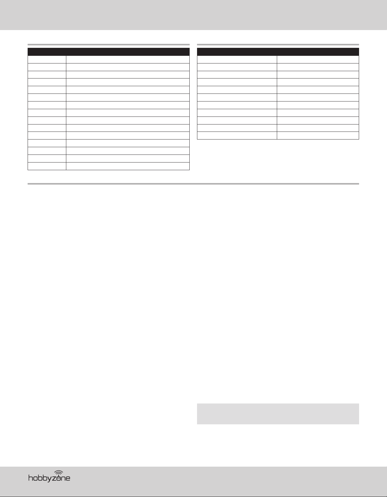
Replacement Parts List Optional Parts List
Part # Description
HBZ3801 Fuselage w/Servos
HBZ3802 Hatch
HBZ3803 Wing Set w/Servos
HBZ3804 Horizontal Fin Set
HBZ3805 Nose Gear w/wheel
HBZ3806 Main Landing Gear Set
HBZ3807 Prop (2)
HBZ3808 30A ESC
HBZ3809 2306-2250 Motor
SPMAR636 AR636 6-Ch AS3X Sport Receiver
SPMR1000 DXe Transmitter Only
SPMSA390 8g Servo
SPMX22003S30 SMART 2200mah 3S 11.1V 30C LiPo; IC3
SPMXC1020 S120 USB-C SMART Charger, 1x20W
HBZ3810 Hardware Set
Limited Warranty
What this Warranty Covers
Horizon Hobby, LLC, (Horizon) warrants to the original purchaser that the
product purchased (the “Product”) will be free from defects in materials and
workmanship at the date of purchase.
What is Not Covered
This warranty is not transferable and does not cover (i) cosmetic damage, (ii)
damage due to acts of God, accident, misuse, abuse, negligence, commercial
use, or due to improper use, installation, operation or maintenance, (iii)
modifi cation of or to any part of the Product, (iv) attempted service by
anyone other than a Horizon Hobby authorized service center, (v) Product not
purchased from an authorized Horizon dealer, or (vi) Product not compliant with
applicable technical regulations, or (vii) use that violates any applicable laws,
rules, or regulations.
OTHER THAN THE EXPRESS WARRANTY ABOVE, HORIZON MAKES NO OTHER
WARRANTY OR REPRESENTATION, AND HEREBY DISCLAIMS ANY AND ALL
IMPLIED WARRANTIES, INCLUDING, WITHOUT LIMITATION, THE IMPLIED
WARRANTIES OF NON-INFRINGEMENT, MERCHANTABILITY AND FITNESS
FOR A PARTICULAR PURPOSE. THE PURCHASER ACKNOWLEDGES THAT THEY
ALONE HAVE DETERMINED THAT THE PRODUCT WILL SUITABLY MEET THE
REQUIREMENTS OF THE PURCHASER’S INTENDED USE.
Purchaser’s Remedy
Horizon’s sole obligation and purchaser’s sole and exclusive remedy shall be
that Horizon will, at its option, either (i) service, or (ii) replace, any Product
determined by Horizon to be defective. Horizon reserves the right to inspect
any and all Product(s) involved in a warranty claim. Service or replacement
decisions are at the sole discretion of Horizon. Proof of purchase is required
for all warranty claims. SERVICE OR REPLACEMENT AS PROVIDED UNDER THIS
WARRANTY IS THE PURCHASER’S SOLE AND EXCLUSIVE REMEDY.
Limitation of Liability
HORIZON SHALL NOT BE LIABLE FOR SPECIAL, INDIRECT, INCIDENTAL
OR CONSEQUENTIAL DAMAGES, LOSS OF PROFITS OR PRODUCTION OR
COMMERCIAL LOSS IN ANY WAY, REGARDLESS OF WHETHER SUCH CLAIM IS
BASED IN CONTRACT, WARRANTY, TORT, NEGLIGENCE, STRICT LIABILITY OR
ANY OTHER THEORY OF LIABILITY, EVEN IF HORIZON HAS BEEN ADVISED OF
THE POSSIBILITY OF SUCH DAMAGES. Further, in no event shall the liability of
Horizon exceed the individual price of the Product on which liability is asserted.
As Horizon has no control over use, setup, fi nal assembly, modifi cation or
misuse, no liability shall be assumed nor accepted for any resulting damage
or injury. By the act of use, setup or assembly, the user accepts all resulting
liability. If you as the purchaser or user are not prepared to accept the liability
associated with the use of the Product, purchaser is advised to return the
Product immediately in new and unused condition to the place of purchase.
Part # Description
DYNC2030 Prophet Sport Mini 50W Charger
EFLA111 LiPo Cell Voltage Checker
SPM6716 Spektrum DSMR Transmitter Case
SPM6722 Spektrum Single Aircraft TX Case
SPMA3051 Standard Servo Extension 6”
SPMR12000 iX12 12 Channel Transmitter Only
SPMR8100 DX8e 8CH Transmitter Only
SPMR9910 DX9 Black Transmitter Only MD2
SPMXBC100 SMART Battery & Servo Tester
SPMXC1000 SMART S1200 DC Charger, 1x200W
SPMXC10201 30A 540W Power Supply
Law
These terms are governed by Illinois law (without regard to confl ict of law
principals). This warranty gives you specifi c legal rights, and you may also
have other rights which vary from state to state. Horizon reserves the right to
change or modify this warranty at any time without notice.
WARRANTY SERVICES
Questions, Assistance, and Services
Your local hobby store and/or place of purchase cannot provide warranty
support or service. Once assembly, setup or use of the Product has been
started, you must contact your local distributor or Horizon directly. This will
enable Horizon to better answer your questions and service you in the event
that you may need any assistance. For questions or assistance, please visit our
website at www.horizonhobby.com, submit a Product Support Inquiry, or call
the toll free telephone number referenced in the Warranty and Service Contact
Information section to speak with a Product Support representative.
Inspection or Services
If this Product needs to be inspected or serviced and is compliant in the
country you live and use the Product in, please use the Horizon Online Service
Request submission process found on our website or call Horizon to obtain a
Return Merchandise Authorization (RMA) number. Pack the Product securely
using a shipping carton. Please note that original boxes may be included,
but are not designed to withstand the rigors of shipping without additional
protection. Ship via a carrier that provides tracking and insurance for lost or
damaged parcels, as Horizon is not responsible for merchandise until it arrives
and is accepted at our facility. An Online Service Request is available at http://
www.horizonhobby.com/content/service-center_render-service-center. If you
do not have internet access, please contact Horizon Product Support to obtain
a RMA number along with instructions for submitting your product for service.
When calling Horizon, you will be asked to provide your complete name, street
address, email address and phone number where you can be reached during
business hours. When sending product into Horizon, please include your RMA
number, a list of the included items, and a brief summary of the problem. A
copy of your original sales receipt must be included for warranty consideration.
Be sure your name, address, and RMA number are clearly written on the
outside of the shipping carton.
NOTICE: Do not ship LiPo batteries to Horizon. If you have any issue
with a LiPo battery, please contact the appropriate Horizon Product
Support offi ce.
Warranty Requirements
For Warranty consideration, you must include your original sales receipt
verifying the proof-of-purchase date. Provided warranty conditions have
been met, your Product will be serviced or replaced free of charge. Service or
replacement decisions are at the sole discretion of Horizon.
®
18
Page 19
Non-Warranty Service
Should your service not be covered by warranty, service will be
completed and payment will be required without notifi cation or estimate
of the expense unless the expense exceeds 50% of the retail purchase
cost. By submitting the item for service you are agreeing to payment of the
service without notifi cation. Service estimates are available upon request. You
must include this request with your item submitted for service. Non-warranty
service estimates will be billed a minimum of ½ hour of labor. In addition you
will be billed for return freight. Horizon accepts money orders and cashier’s
checks, as well as Visa, MasterCard, American Express, and Discover cards. By
submitting any item to Horizon for service, you are agreeing to Horizon’s Terms
and Conditions found on our website http://www.horizonhobby.com/content/
service-center_render-service-center.
ATTENTION: Horizon service is limited to Product compliant in the
country of use and ownership. If received, a non-compliant Product will
not be serviced. Further, the sender will be responsible for arranging
return shipment of the un-serviced Product, through a carrier of the
sender’s choice and at the sender’s expense. Horizon will hold noncompliant Product for a period of 60 days from notifi cation, after which
it will be discarded.
Contact Information
Country of Purchase Horizon Hobby Contact Information Address
United States of America
European Union
Horizon Service Center
(Repairs and Repair Requests)
Horizon Product Support
(Product Technical Assistance)
Sales
Horizon Technischer Service service@horizonhobby.eu
Sales: Horizon Hobby GmbH +49 (0) 4121 2655 100
servicecenter.horizonhobby.com/
RequestForm/
productsupport@horizonhobby.com
877-504-0233
websales@horizonhobby.com
800-338-4639
2904 Research Road
Champaign, Illinois, 61822 USA
Hanskampring 9
D 22885 Barsbüttel, Germany
EN
10/15
FCC Information
FCC ID: BRWDXE
BRWDASRX15
This device complies with part 15 of the FCC rules. Operation is subject to the following two conditions: (1) This device may not cause harmful interference, and
(2) this device must accept any interference received,
including interference that may cause undesired operation.
CAUTION: Changes or modifi cations not expressly approved by the party responsible for compliance could void the user’s authority to operate the equipment.
This product contains a radio transmitter with wireless technology which has been tested and found to be compliant with the applicable regulations governing a
radio transmitter in the 2.400GHz to 2.4835GHz frequency range.
Supplier’s Declaration of Conformity
HBZ AeroScout S 1.1m RTF, BNF Basic (HBZ3800, HBZ3850)
BRWDXE
BRWDASRX15
This device complies with part 15 of the FCC Rules. Operation is subject to the following two conditions: (1) This device may not cause harmful interference,
and (2) this device must accept any interference received, including interference that may cause undesired operation.
CAUTION: Changes or modifi cations not expressly approved by the party responsible for compliance could void the user’s authority to operate the equipment.
NOTE: This equipment has been tested and found to comply with the limits for a Class B digital device, pursuant to part 15 of the FCC Rules. These limits
are designed to provide reasonable protection against harmful interference in a residential installation. This equipment generates, uses and can radiate radio
frequency energy and, if not installed and used in accordance with the instructions, may cause harmful interference to radio communications. However, there is no
guarantee that interference will not occur in a particular installation. If this equipment does cause harmful interference to radio or television reception, which can
be determined by turning the equipment off and on, the user is encouraged to try to correct the interference by one or more of the following measures:
• Reorient or relocate the receiving antenna.
• Increase the separation between the equipment and receiver.
• Connect the equipment into an outlet on a circuit different from that to which the receiver is connected.
• Consult the dealer or an experienced radio/TV technician for help.
Horizon Hobby, LLC
2904 Research Rd.,
Champaign, IL 61822
Email: compliance@horizonhobby.com
Web: HorizonHobby.com
19
AeroScout S
Page 20
EN
IC Information
IC: 6157A-DXE
6157A-AMRX15
CAN ICES-3 (B)/NMB-3(B)
This device complies with Industry Canada licence-exempt RSS standard(s). Operation is subject to the following two conditions:
(1)this device may not cause interference, (2)this device must accept any interference, including interference that may cause undesired operation of
the device.
Compliance Information for the European Union
HBZ AeroScout S 1.1m RTF (HBZ3800)
EU Compliance Statement: Horizon Hobby, LLC hereby declares
that this product is in compliance with the essential requirements
and other relevant provisions of the RED and EMC directives.
A copy of the EU Declaration of Conformity is available online at: http://www.horizonhobby.com/content/support-render-compliance.
Instructions for disposal of WEEE by users in the European Union
This product must not be disposed of with other waste. Instead, it
is the user’s responsibility to dispose of their waste equipment by
handing it over to a designated collections point for the recycling
of waste electrical and electronic equipment. The separate
collection and recycling of your waste equipment at the time of
CHBZ AeroScout S 1.1m BNF Basic (HBZ3850)
EU Compliance Statement: Horizon Hobby, LLC hereby declares that this
product is in compliance with the essential requirements and other relevant
provisions of the RED and EMC directives.
disposal will help to conserve natural resources and ensure that it is recycled
in a manner that protects human health and the environment. For more
information about where you can drop off your waste equipment for recycling,
please contact your local city offi ce, your household waste disposal service or
where you purchased the product.
®
20
Page 21

AMA National Model Aircraft Safety Code
Effective January 1, 2014
A. GENERAL
A model aircraft is a non-human-carrying aircraft capable of sustained fl ight
in the atmosphere. It may not exceed limitations of this code and is intended
exclusively for sport, recreation, education and/or competition. All model fl ights
must be conducted in accordance with this safety code and any additional
rules specifi c to the fl ying site.
1. Model aircraft will not be fl own:
(a) In a careless or reckless manner.
(b) At a location where model aircraft activities are prohibited.
2. M odel aircraft pilots will:
(a) Yield the right of way to all man carrying aircraft.
(b) See and avoid all aircraft and a spotter must be used when appropriate.
(AMA Document #540-D.)
(c) Not fl y higher than approximately 400 feet above ground level within
three (3) miles of an airport, without notifying the airport operator.
(d) Not interfere with operations and traffi c patterns at any airport, heliport
or seaplane base except where there is a mixed use agreement.
(e) Not exceed a takeoff weight, including fuel, of 55 pounds unless
in compliance with the AMA Large Model Aircraft program. (AMA
Document 520-A.)
(f) Ensure the aircraft is identifi ed with the name and address or AMA
number of the owner on the inside or affi xed to the outside of the model
aircraft. (This does not apply to model aircraft fl own indoors).
(g) Not operate aircraft with metal-blade propellers or with gaseous boosts
except for helicopters operated under the provisions of AMA Document
#555.
(h) Not operate model aircraft while under the infl uence of alcohol or while
using any drug which could adversely affect the pilot’s ability to safely
control the model.
(i) Not operate model aircraft carrying pyrotechnic devices which explode
or burn, or any device which propels a projectile or drops any object that
creates a hazard to persons or property.
Exceptions:
• Free Flight fuses or devices that burn producing smoke and are
securely attached to the model aircraft during fl ight.
• Rocket motors (using solid propellant) up to a G-series size may be
used provided they remain attached to the model during fl ight. Model
rockets may be fl own in accordance with the National Model Rocketry
Safety Code but may not be launched from model aircraft.
• Offi cially designated AMA Air Show Teams (AST) are authorized to use
devices and practices as defi ned within the Team AMA Program Document (AMA Document #718).
(j) Not operate a turbine-powered aircraft, unless in compliance with the
AMA turbine regulations. (AMA Document #510-A).
3. Model aircraft will not be fl own in AMA sanctioned events, air shows or
model demonstrations unless:
(a) The aircraft, control system and pilot skills have successfully
demonstrated all maneuvers intended or anticipated prior to the specifi c
event.
(b) An inexperienced pilot is assisted by an experienced pilot.
4. When and where required by rule, helmets must be properly worn and
fastened. They must be OSHA, DOT, ANSI, SNELL or NOCSAE approved or
comply with comparable standards.
EN
B. RADIO CONTROL
1. All pilots shall avoid fl ying directly over unprotected people, vessels,
vehicles or structures and shall avoid endangerment of life and property of
others.
2. A successful radio equipment ground-range check in accordance with
manufacturer’s recommendations will be completed before the fi rst fl ight of
a new or repaired model aircraft.
3. At all fl ying sites a safety line(s) must be established in front of which all
fl ying takes place (AMA Document #706.)
(a) Only personnel associated with fl ying the model aircraft are allowed at
or in front of the safety line.
(b) At air shows or demonstrations, a straight safety line must be
established.
(c) An area away from the safety line must be maintained for spectators.
(d) Intentional fl ying behind the safety line is prohibited.
4. RC model aircraft must use the radio-control frequencies currently allowed
by the Federal Communications Commission (FCC). Only individuals
properly licensed by the FCC are authorized to operate equipment on
Amateur Band frequencies.
5. RC model aircraft will not operate within three (3) miles of any pre-existing
fl ying site without a frequency-management agreement (AMA Documents
#922 and #923.)
6. With the exception of events fl own under offi cial AMA Competition
Regulations, excluding takeoff and landing, no powered model may be
fl own outdoors closer than 25 feet to any individual, except for the pilot and
the pilot’s helper(s) located at the fl ight line.
7. Under no circumstances may a pilot or other person touch a model aircraft
in fl ight while it is still under power, except to divert it from striking an
individual.
8. RC night fl ying requires a lighting system providing the pilot with a clear
view of the model’s attitude and orientation at all times. Hand-held
illumination systems are inadequate for night fl ying operations.
9. The pilot of a RC model aircraft shall:
(a) Maintain control during the entire fl ight, maintaining visual contact
without enhancement other than by corrective lenses prescribed for the
pilot.
(b) Fly using the assistance of a camera or First-Person View (FPV) only in
accordance with the procedures outlined in AMA Document #550.
(c) Fly using the assistance of autopilot or stabilization system only in
accordance with the procedures outlined in AMA Document #560.
Please see your local or regional modeling association’s guidelines for
proper, safe operation of your model aircraft.
21
AeroScout S
Page 22
DE
HINWIES
Allen Anweisungen, Garantien und anderen zugehörigen Dokumenten sind Änderungen nach Ermessen von Horizon Hobby, LLC vorbehalten. Aktuelle
Produktliteratur finden Sie unter www.horizonhobby.com oder www.towerhobbies.com im Support-Abschnitt für das Produkt.
BEGRIFFSERKLÄRUNG
Die folgenden Begriffe werden in der gesamten Produktliteratur verwendet, um auf unterschiedlich hohe Gefahrenrisiken beim Betrieb dieses Produkts hinzuweisen:
WARNUNG: Wenn diese Verfahren nicht korrekt befolgt werden, ergeben sich wahrscheinlich Sachschäden, Kollateralschäden und schwere Verletzungen ODER
mit hoher Wahrscheinlichkeit oberfl ächliche Verletzungen.
ACHTUNG: Wenn diese Verfahren nicht korrekt befolgt werden, ergeben sich wahrscheinlich Sachschäden UND die Gefahr von schweren Verletzungen.
HINWEIS: Wenn diese Verfahren nicht korrekt befolgt werden, können sich möglicherweise Sachschäden UND geringe oder keine Gefahr von Verletzungen ergeben.
WARNUNG: Lesen Sie die GESAMTE Bedienungsanleitung, um sich vor dem Betrieb mit den Produktfunktionen vertraut zu machen. Wird das Produkt
nicht korrekt betrieben, kann dies zu Schäden am Produkt oder persönlichem Eigentum führen oder schwere Verletzungen verursachen.
Dies ist ein hochentwickeltes Hobby-Produkt. Es muss mit Vorsicht und gesundem Menschenverstand betrieben werden und benötigt gewisse mechanische
Grundfähigkeiten. Wird dieses Produkt nicht auf eine sichere und verantwortungsvolle Weise betrieben, kann dies zu Verletzungen oder Schäden am
Produkt oder anderen Sachwerten führen. Versuchen Sie nicht ohne Genehmigung durch Horizon Hobby, LLC, das Produkt zu zerlegen, es mit inkompatiblen
Komponenten zu verwenden oder auf jegliche Weise zu erweitern. Diese Bedienungsanleitung enthält Anweisungen für Sicherheit, Betrieb und Wartung. Es ist
unbedingt notwendig, vor Zusammenbau, Einrichtung oder Verwendung alle Anweisungen und Warnhinweise im Handbuch zu lesen und zu befolgen, damit es
bestimmungsgemäß betrieben werden kann und Schäden oder schwere Verletzungen vermieden werden.
Nicht geeignet für Kinder unter 14 Jahren. Dies ist kein Spielzeug.
+
14
Sicherheits maßnahmen und Warnungen
Als Benutzer dieses Produkts sind ausschließlich Sie für einen Betrieb
verantwortlich, der weder Sie selbst noch andere gefährdet, bzw. der weder
das Produkt noch Eigentum anderer beschädigt.
• Halten Sie stets in alle Richtungen einen Sicherheitsabstand zu Ihrem
Modell ein, um Kollisionen und Verletzungen zu vermeiden. Dieses Modell
wird über ein Funksignal gesteuert. Funksignale können von außerhalb
gestört werden, ohne dass Sie darauf Einfl uss nehmen können. Störungen
können zu einem vorübergehenden Verlust der Steuerungskontrolle führen.
• Betreiben Sie Ihr Modell stets auf offenen Geländen, weit ab von Autos,
Verkehr und Menschen.
• Befolgen Sie die Anweisungen und Warnungen für dieses Produkt und
jedwedes optionales Zubehörteil (Ladegeräte, wieder aufl adbare Akkus etc.)
stets sorgfältig.
• Halten Sie sämtliche Chemikalien, Kleinteile und elektrische Komponenten
stets außer Reichweite von Kindern.
• Vermeiden Sie den Wasserkontakt aller Komponenten, die nicht speziell
dafür ausgelegt und entsprechend geschützt sind. Feuchtigkeit beschädigt
die Elektronik.
WARNUNG VOR GEFÄLSCHTEN PRODUKTEN: Sollten Sie jemals eine Spektrum Komponente ersetzen wollen, kaufen Sie die benötigten Ersatzteile
immer bei Horizon Hobby oder einem von Horizon Hobby autorisierten Händler, um sicherzugehen, dass Sie beste Spektrum Qualität erhalten. Horizon
Hobby, LLC lehnt jedwede Haftung, Garantie und Serviceleistung in Bezug auf, aber nicht ausschließlich für, Kompatibilitäts- und Leistungsansprüche von
gefälschten Produkten oder Produkten, die angeben mit DSM oder Spektrum kompatibel zu sein, ab.
• Nehmen Sie niemals ein Element des Modells in Ihren Mund, da dies zu
schweren Verletzungen oder sogar zum Tod führen könnte.
• Betreiben Sie Ihr Modell niemals mit schwachen Senderbatterien.
• Behalten Sie das Modell stets im Blick und unter Kontrolle.
• Verwenden Sie nur vollständig aufgeladene Akkus.
• Behalten Sie den Sender stets eingeschaltet, wenn das Modell
eingeschaltet ist.
• Entfernen Sie stets den Akku, bevor Sie das Modell auseinandernehmen.
• Halten Sie bewegliche Teile stets sauber.
• Halten Sie die Teile stets trocken.
• Lassen Sie die Teile stets auskühlen, bevor Sie sie berühren.
• Entfernen Sie nach Gebrauch stets den Akku.
• Stellen Sie immer sicher, dass der Failsafe vor dem Flug ordnungsgemäß
eingestellt ist.
• Betreiben Sie das Modell niemals bei beschädigter Verkabelung.
• Berühren Sie niemals sich bewegende Teile.
®
22
Page 23
Packungsinhalt
Inhaltsverzeichnis
DE
Spezifi kationen ............................................................................................. 23
Akku-Warnhinweise ...................................................................................... 24
Flug-Akku laden ........................................................................................... 24
Senderprogrammierung ................................................................................ 25
Mitgelieferter DXe-Sender (RTF-Version) ....................................................... 26
Flugzeug zusammenbauen ...........................................................................27
Sender und Empfänger binden ...................................................................... 29
Flugakku einsetzen ....................................................................................... 29
Schwerpunkt (CG) ......................................................................................... 30
Steuerrichtungstest ...................................................................................... 30
Die Auswahl eines Flugfeldes ........................................................................ 31
Reichweitentest ............................................................................................ 31
Den Propeller anbringen ............................................................................... 32
Flugmodi der SAFE-(Sensor Assisted Flight Envelope-)Technologie ...............32
Spezifi kationen
1095mm
867mm
788-836 g
Flugsteuerung ............................................................................................... 33
Checkliste vor dem Flug................................................................................ 34
Fliegend........................................................................................................ 34
Trimmung des Flugzeugs .............................................................................. 35
Checkliste nach dem Flug ............................................................................. 36
Werkseitige Einstellungen der Steuerhörner und Servo-Arme ........................ 36
Service and Repairs ......................................................................................36
Leitfaden zur Problemlösung AS3X ................................................................ 37
Leitfaden zur Problemlösung ......................................................................... 37
Ersatzteile ..................................................................................................... 38
Optionale Bauteile ......................................................................................... 38
Garantie und Service Informationen ..............................................................38
Garantie und Service Kontaktinformationen................................................... 39
Rechtliche Informationen für die Europäische Union ...................................... 39
Motor: 2306-2250 Bürstenloser Außenläufer
(HBZ3809)
Geschwindigkeitsregler: 30A (HBZ3808) Montiert Montiert
Servos: 8g Servo (SPMSS390) Montiert Montiert
Empfänger: AR636 AS3X Sportempfänger
mit 6 Kanälen (SPMAR636
Akku: SMART 2200mAh 3S 11,1V 30C
LiPo; IC3 (SPMX22003S30)
Akkuladegerät: S120 USB-C SMART-
Ladegerät, 1x20W (SPMXC1020)
Sender: Spektrum DXe mit kompletter DSMX
Technologie
Montiert Montiert
Montiert Montiert
Beiliegend
Beiliegend
Beiliegend
Extra
erhältlich
Extra
erhältlich
Extra
erhältlich
23
AeroScout S
Page 24

DE
Akku-Warnhinweise
ACHTUNG: Alle Anweisungen und Warnhinweise müssen genau
befolgt werden. Falsche Handhabung von Li-Po-Akkus kann zu Brand,
Personen- und/oder Sachwertschäden führen.
• LASSEN SIE LADEN VON AKKUS UNBEAUFSICHTIGT.
• LADEN SIE NIEMALS AKKUS ÜBER NACHT.
• Durch Handhabung, Aufl adung oder Verwendung des mitgelieferten
Li-Po-Akkus übernehmen Sie alle mit Lithiumakkus verbundenen Risiken.
• Sollte der Akku zu einem beliebigen Zeitpunkt beginnen, sich aufzublähen
oder anzuschwellen, stoppen Sie die Verwendung unverzüglich. Falls dies
beim Laden oder Entladen auftritt, stoppen Sie den Lade-/Entladevorgang,
und entnehmen Sie den Akku. Wird ein Akku, der sich aufbläht oder
anschwillt, weiter verwendet, geladen oder entladen, besteht Brandgefahr.
• Lagern Sie den Akku stets bei Zimmertemperatur an einem trockenen Ort.
• Bei Transport oder vorübergehender Lagerung des Akkus muss der
Temperaturbereich zwischen 40°F und 120°F (ca. 5 – 49°C) liegen. Akku
oder Modell dürfen nicht im Auto oder unter direkter Sonneneinstrahlung
gelagert werden. Bei Lagerung in einem heißen Auto kann der Akku
beschädigt werden oder sogar Feuer fangen.
Flug-Akku laden
Der empfohlene Akku für das HobbyZone AeroScout S Fluggerät, der in der
RTF-Version mitgeliefert wird, ist ein 11,1V, 2200mAh 3S 30C Smart Technology
LiPo-Akku mit einem IC3-Steckern (SPMX22003S30). Wird ein anderer Akku
verwendet, dann sollte dieser in Leistung, Abmessungen und Gewicht ähnlich
sein, damit er in den Rumpf passt. Der Geschwindigkeitsregler des Fluggeräts
ist mit einem IC3-Gerätestecker ausgerüstet. Sicherstellen, dass der gewählte
Akku kompatibel ist. Immer sicherstellen, dass das Modell mit dem gewählten
Akku am empfohlenen Schwerpunkt (CG) ausbalanciert ist. Die Anweisungen des
gewählten Akkus und des Akkuladegeräts zum Laden des Flug-Akkus befolgen.
RTF Smart Technology Akku und S120-Ladegerät,
Spezifi kationen und Betrieb
Das mit der RTF-Version des Fluggeräts mitgelieferte Spektrum S120 SMART
Technology Ladegerät ist nur mit Spektrum SMART 2–3 zelligen LiPoAkkus oder 6–7-zelligen NiMH-Akkus kompatibel. Es ist nicht mit anderen
Akkuchemien oder nicht-SMART-Akkus kompatibel.
Ein USB-Netzteil ist für den Betrieb erforderlich. Für schnellste Ladezeiten wird
ein Netzteil vom Typ USB-C QC empfohlen.
S120-Spezifi kationen
Eingabe
Eingangsspannung 5V-12V
Ladeleistung max. 18W (abhängig von der Stromversorgung)
Kompatibler USB Netzadapter 5V/1A, 5V/2A, USB Quick Charge (QC) 2.0/3.0
Akku-Anschluss IC3 und Ausgleichsstecker
Akkutypen LiPo, NiMH (nur Spektrum SMART-Akkus)
Anzahl der Zellen 2–3 Zellen LiPo, 6–7 Zellen NiMH
Max. Ausgangsleistung 13,05V
Max. Ausgangsstrom Bis zu 2A
USB-C-Anschluss LED-Anzeige
USB vom Typ C, Netzteil nicht im Lieferumfang enthalten
Ausgleichsanschluss
IC3-Ladeanschluss
• Laden Sie die Akkus immer weit entfernt von brennbaren Materialien.
• Überprüfen Sie immer den Akku vor dem Laden und laden Sie niemals
defekte oder beschädigte Akkus.
• Verwenden Sie ausschließlich ein Ladegerät das speziell für das Laden von
LiPo Akku geeignet ist. Das Laden mit einem nicht geeignetem Ladegerät
kann Feuer und / oder Sachbeschädigung zur Folge haben.
• Überwachen Sie ständig die Temperatur des Akkupacks während des Ladens.
• Trennen Sie immer den Akku nach dem Laden und lassen das Ladegerät
abkühlen.
• Entladen Sie niemals ein LiPo Akku unter 3V pro Zelle unter Last.
• Verdecken Sie niemals Warnhinweise mit Klettband.
• Lassen Sie niemals Akkus während des Ladens unbeaufsichtigt.
• Laden Sie niemals Akkus ausserhalb ihrer sicheren Grenzen.
• Laden Sie nur Akkus die kühl genug zum anfassen sind.
• Versuchen Sie nicht das Ladegerät zu demontieren oder zu verändern.
• Lassen Sie niemals Minderjährige Akkus laden.
• Laden Sie niemals Akkus an extrem kalten oder heißen Plätzen
(empfohlener Temperaturbereich 5 – 49°) oder im direkten Sonnenlicht.
Zum Laden des mitgelieferten Flug-Akkus:
1. Das S120-Ladegerät mit dem mitgelieferten USB-Kabel vom Typ C an ein
USB-Netzteil (nicht im Lieferumfang enthalten) anschließen.
2. Den Spektrum SMART
Akku-IC3-Stecker (A)
in die IC3-Ladebuchse
am S120-Ladegerät
stecken und das AkkuAusgleichskabel (B) in den
Ausgleichsanschluss des
Ladegeräts einführen. Die
IC3- und Ausgleichsstecker
müssen eingesteckt sein,
ehe der Ladevorgang
starten kann. Um den Ladevorgang zu unterbrechen, kann der Akku jederzeit
vom Ladegerät getrennt werden.
WICHTIG: SMART NiMH-Akkus verfügen nicht über einen Ausgleichsstecker.
3. Die IC3- und Ausgleichsstecker trennen, wenn die Lade- und
Ausgleichszyklen abgeschlossen sind. Dies wird durch die LED angezeigt.
4. Die LED-Anzeige wird bei einem Ladefehler durchgängig rot leuchten.
Befolgen Sie die Verfahrensschritte, um sicherzustellen, dass der richtige
Anschluss zum Laden des Akkus verwendet wird.
Den Status des Ladegeräts entnehmen Sie bitte der Tabelle mit den LEDAnzeigen auf der vorherigen Seite.
WICHTIG: Durch das Anschließen eines Akkus, der nicht vom Smart-Typ ist,
Einschalten
LiPo: Violettfarbene LED
NiMH: Gelbe LED
Laden abgeschlossen Grüne LED (durchgängig)
Fehler Rote LED (durchgängig)
wird ein Ladefehler verursacht und der S120 wird den Akku nicht
erkennen oder aufl aden.
LED-Anzeige
USB 5V: Weiße LED
USB Quick Charge 2.0/3.0: Blaue LED
Unter 25% Einmaliges Blinken
25% – 75% Zweimaliges Blinken
76% – 99% Dreimaliges Blinken
A
Akkukapazität
B
®
24
Page 25

WARNUNG: Bauen Sie vor weiteren Schritten zunächst den Propeller und den Spinner von der Motorwelle
ab. Versuchen Sie niemals, die Funkkomponenten zu programmieren, das Fluggerät zusammenzubauen
oder Wartungseingriffe irgendeiner Art vorzunehmen, ohne zuvor den Propeller zu entfernen. Sollte der Motor
unbeabsichtigt mit dem noch befestigten Propeller starten, kann dies zu schweren Verletzungen führen.
1. Stellen Sie sicher, dass der Flug-Akku NICHT mit dem
Flugzeug verbunden ist.
2. Durch das Festhalten des Motors kann sich dieser
nicht drehen.
3. Den Propeller und die Propeller-Mutter zum Lösen
von der Motorwelle im Uhrzeigersinn drehen.
4. Den Propeller, dessen Mutter und Unterlegscheibe
entfernen.
Senderprogrammierung
DE
Wird ein beliebiger DSMX-Sender und nicht der mitgelieferte DXe-Sender
(3-Positionen-Getriebeschalter, nur RTF) verwendet, so muss das Funksystem für
den ordnungsgemäßen Betrieb des SAFE-Systems korrekt konfi guriert werden.
• Der SAFE-Flugmodus wird mit einem Signal von Kanal 5 (hoch, mittel,
niedrig) ausgewählt
• Der Panikmodus wird mit einem Signal von Kanal 6 (hoch, niedrig)
ausgewählt
Weitere Informationen über die Einrichtung des Senders fi nden Sie in der
Sender-Betriebsanleitung.
Bei der Verwendung eines 2-Positionen-Schalters für die SAFE-Flugmodi sind
nur die Modi Beginner (Anfänger) und Experienced (Experte) aktiv.
Jeder DXe-Sender, dem ein HBZ AeroScout RTF fehlt, muss für den
ordnungsgemäßen Betriebs dieses Fluggeräts mit dem Spektrum Programmer
(SPMA3065) programmiert werden. Unter www.spektrumrc.com steht das
korrekte Programm für dieses Fluggerät zum Download bereit.
Computergestützte Senderkonfi guration
(DX6 Gen2, DX6e,DX7 Gen2, DX8 Gen2, DX9, iX12, DX18 und DX20)
Die gesamte Senderprogrammierung mit einem leeren Modell (eine
Zurücksetzung des Modells durchführen) beginnen, dann das Modell benennen.
Stellen Sie die Werte für
Querruder, Höhenruder und
Ruder wie folgt ein:
SYSTEMKONFIGURATION (SYSTEM SETUP) einstellen
MODELLTYP (MODEL TYPE) einstellen: FLUGZEUG
Zur KANALZUWEISUNG (CHANNEL ASSIGN) gehen:
DX6
DX6e
DX8
DX9
iX12
DX20
Auf WEITER (NEXT) klicken, um die Kanaleingabekonfi guration
Die FUNKTIONSLISTE (FUNCTION LIST) aufrufen
Die Gasdrosselung (Throttle Cut) einstellen:
auf Schalter H, Position: -130
Ergebnis:
(Channel Input Confi g) aufzurufen:
GEAR: B, AUX1: I
HOCH 100 %
NIEDRIG 70 %
Schalter H aktiviert die Gasdrosselung
(Throttle Cut), Position 0 ist normal und
Position 1 drosselt das Gas.
Schalter B aktiviert die 3 SAFE Plus Modi
(0Anfänger/1 Fortgeschrittene /2 Experten)
Knopf I aktiviert Panikmodus
25
AeroScout S
Page 26

DE
Mitgelieferter DXe-Sender (RTF-Version)
Die Sender-Akkus einsetzen
Die Akku-Abdeckung abnehmen, die vier im Lieferumfang enthaltenen Akkus
(unter Beachtung der richtigen Polarität) einsetzen und Akku-Abdeckung
wieder anbringen.
Alarm niedriger Akkustand
Die LED-Anzeige blinkt und der Sender gibt einen Piepton ab, der zunehmend
schneller wird, während die Akku-Spannung fällt.
Die Sender-Akkus ersetzen, wenn der Sender beginnt, einen Piepton abzugeben.
ACHTUNG: Bei der Verwendung von wiederaufl adbaren Akkus dürfen
auch nur solche erneut geladen werden. Das Laden von normalen,
nicht wiederaufl adbaren Akkus kann ein Platzen der Akkus und damit
verbundene Personen- und/oder Sachschäden verursachen.
WARNUNG: Den Sender zum Heben nicht an der Antenne fassen. Die
Antenne nicht verändern und kein Gewicht hinzufügen.
Beschädigungen der Antennenteile können die Signalstärke des Senders
mindern; dadurch kann es zu einem Kotrollverlust über das Modell und
Personen- oder Sachschäden kommen.
Sendersteuerung des RTF-Senders
Das Diagramm zeigt die Sendersteuerung des
mitgelieferten DXe-Senders.
LED-Anzeige
SAFE Plus-
Modusschalter
BIND-/PANIC-Knopf
(Binden-/PANIK-)
Gas/Ruder
Gastrimmung
Trimmung Ruder
Drahtloser Trainerund Bindungsschalter
Gasabschaltungsschalter
Hoch-/NiedrigGeschwindigkeitsschalter
Steuerknüppel
Höhenruder/Querruder
Trimmung Höhenruder
Trimmung Querruder
Stromschalter
®
26
Page 27

Flugzeug zusammenbauen
Einbau des Fahrwerks
1. Das Hauptfahrwerk in die Schlitze im Rumpf schieben, bis sie einrasten.
2. Das Bugfahrwerk in die Anschlaghülse entsprechend der Abbildung
einfügen und die Feststellschraube an der Flachstelle des Fahrwerk-Kabels
mit einem Kreuzschlitzschraubendreher festziehen.
DE
Das Höhenleitwerk montieren
1. Das längere der zwei mitgelieferten Kohlefasern-Vierkantrohr vollständig
in die Öffnung eines der beiden Höhenleitwerke schieben. Das Rohr wurde
formgepresst und benötigt keinen Klebstoff.
2. Das Rohr durch die Öffnung im Seitenleitwerk des Rumpfs entsprechend
der Abbildung einführen, bis das bereits montierte Höhenleitwerk gegen
den Rumpf liegt.
WICHTIG: Die Decals am Höhenleitwerk müssen bei korrekter Montage der
Leitwerke nach oben weisen.
3. Das gegenüberliegende Höhenleitwerk über das andere Rohrende
schieben. Die Leitwerkhälften gegeneinander drücken, bis beide auf dem
Rohr vollständig sitzen und es nur einen kleinen Spalt zwischen den
Leitwerken und dem Rumpf gibt.
27
AeroScout S
Page 28

DE
Flügel zusammenbauen und montieren
1. Den Kohlefaser-Tragfl ächenholm entsprechend der Abbildung vollständig
auf eine Tragfl äche schieben. Sicherstellen, dass die Servoleitung des
Querruders durch den Schlitz auf der Unterseite des Flügels austritt.
2. Die gegenüberliegende Tragfl äche über den Tragfl ächenholmen schieben,
bis die Tragfl ächenwurzeln eng anliegen und das hintere Befestigungsloch
korrekt ausgerichtet ist. Sicherstellen, dass beide Servoleitungen des
Querruders an der Unterseite der Tragfl äche austreten und nicht zwischen
den Tragfl ächen eingeklemmt sind.
3. Die Servoleitungen des Querruders an den im Kanal 2 des Empfängers
montierten Y-Kabelbaum anschließen.
4. Die Tragfl äche auf dem Rumpf zentrieren. Sicherstellen, dass die
Servoleitungen des Querruders nicht zwischen der Tragfl äche und dem
Rumpf eingeklemmt sind.
5. Die Tragfl äche mit den mitgelieferten 50mm Schrauben anbringen. Die
Flügelschrauben nicht zu fest anziehen, da es dadurch zu Schäden an der
Tragfl äche oder den Befestigungspunkten im Rumpf kommen kann.
WICHTIG: Die Flügelschrauben können während den ersten Montagen im
Rumpf einen festen Sitz aufweisen. Bei Bedarf einen Schraubendreher
verwenden, bis die Befestigungspunkte sich ausreichend lockern, damit die
Schrauben per Hand montiert werden können.
HINWEIS: Die Flügelschrauben nicht zu fest anziehen. Dadurch wird der
Schaumstoff der Tragfl äche zerdrückt oder die Befestigungspunkte des
Rumpfs beschädigt.
®
28
Page 29

Sender und Empfänger binden
DE
ACHTUNG: Das Anschließen des Akkus an Geschwindigkeitsregler mit
umgekehrter Polarität wird Schäden am Geschwindigkeitsregler, dem
Akku oder beiden verursachen. Schäden durch das falsche Anschließen des
Akkus werden nicht durch die Garantie gedeckt.
Mit der Verlängerung am Bindungsanschluss des Empfängers kann eine Bindung
über die Akku-Abdeckung auf der Vorderseite des Fluggeräts hergestellt werden,
ohne die Flügelbaugruppe abbauen zu müssen. Den Bindungsanschluss einfach
am offenen Ende der Verlängerung einsetzen, um den Bindungsmodus zu starten.
Der mit dem RTF-Modell mitgelieferte Sender wird werkseitig an das Fluggerät
gebunden. Wenn er aus irgendeinem Grund neu gebunden werden muss, folgen
Sie der abgebildeten Bindungsprozedur.
Die BNF-Version dieses Fluggeräts erfordert für den korrekten Betrieb einen mit
der Spektrum DSM2/DSMX Technologie ausgestatteten Fluggeräte-Sender.
Beziehen Sie sich für die Bindung an einen Empfänger auf die Anweisungen
Ihres Senders.
Treten Probleme trotz des Befolgens der Anweisungen zum Binden auf, so
kontaktieren Sie bitte die entsprechende Produktsupport-Abteilung von Horizon.
Vorgehensweise zur Bindung
1. Sicherstellen, dass der Sender ausgeschaltet ist.
2. Vergewissern Sie sich, dass die Steuerelemente des Senders in
Nullstellung sind, das Gas in der niedrigsten* Position steht, die
Gastrimmung zentriert ist und das Fluggerät stillsteht.
3. Einen Bindungsstecker an der Verlängerung des Bindungsanschlusses des
Empfängers anbringen.
4. Den Flug-Akku am Geschwindigkeitsregler anschließen. Der
Geschwindigkeitsregler wird drei ansteigende Töne abgeben und die LED
des Empfängers fängt an, schnell zu blinken.
5. Siehe die Betriebsanleitung des Senders zu spezifi schen Anweisungen,
um den Sender in den Bindungsmodus zu bringen.
6. Wenn sich der Empfänger am Sender bindet, leuchtet die LED
des Empfängers durchgängig und das Fluggerät startet den
Initialisierungsprozess, der durch das Hin- und Herschalten der
Steueroberfl ächen angezeigt wird.
7. Den Bindungsstecker von der Bindungsanschlussverlängerung entfernen
und an einem sicheren Ort lagern. Der Empfänger muss die vom Sender
erhaltenen Bindungsanweisungen speichern, bis eine erneute Bindung erfolgt.
* Das Gas wird nicht aktiviert, wenn der Gashebel des Senders nicht auf die
niedrigste Stellung eingestellt ist.
Flugakku einsetzen
1. Den Sender einschalten.
2. Den MOTOR-Schalter des Senders auf „DISARM“ (Ausschalten) stellen.
3. Die Akku-Abdeckung am hinteren Teil anheben, um sie vom Rumpf zu lösen.
4. Ein Stück des selbstklebenden Klettbandes mit der Schlingenseite auf der
Unterseite des Akkus anbringen.
5. Den Akku in die Akkuhalterung platzieren, wobei die Schlingenseite nach
unten weist. Die Platzierung des Akkus kann zum Ausbalancieren des
Fluggeräts nach vorn oder nach hinten angepasst werden.
6. Ist der Akku korrekt platziert, diesen mit Klettband sichern.
7. Den IC3-Akkustecker am Geschwindigkeitsregler mit der richtigen Polarität
anschließen.
ACHTUNG: Das Anschließen des Akkus an Geschwindigkeitsregler mit
umgekehrter Polarität wird Schäden am Geschwindigkeitsregler, dem
Akku oder beiden verursachen. Schäden durch das falsche Anschließen des
Akkus werden nicht durch die Garantie gedeckt.
ACHTUNG: Die Hände immer vom Propeller fernhalten. Der Motor
reagiert im eingeschalteten Zustand auf eine Bewegung des
Gashebels mit einer Drehung des Propellers.
8. Das Fluggerät auf eine fl ache, ebene Fläche stellen. Die Steueroberfl ächen
schalten während der Initialisierung des SAFE-Systems hin und her. Die
Initialisierung ist abgeschlossen, wenn sich die Steueroberfl ächen nicht
mehr bewegen.
9. Die Akku-Abdeckung wieder im Rumpf einsetzen, indem zuerst die vordere
Lasche eingeführt wird und dann die hintere, bis der Magnet schließt.
ACHTUNG: Der LiPo-Flugakku muss immer vom Flugzeug getrennt werden,
wenn es nicht verwendet wird, um ein übermäßiges Entladen des Akkus zu
vermeiden. Akkus, die auf eine niedrigere Spannung als die niedrigste zugelassene
Spannung entladen werden, können Schaden nehmen, und es kann so zu
Leistungsverlusten und möglichen Bränden beim Laden der Akkus kommen.
29
AeroScout S
Page 30

DE
Schwerpunkt (CG)
Bei einem Fluggerät mit dem richtigen Schwerpunkt ist das Gewicht für einen
sicheren, stabilen Flug in der Mitte des Flugzeugs ausbalanciert. Schwerpunkt
und Gewicht des Flugzeugs basieren auf dem installierten Akku.
Die Position des Schwerpunkts befi ndet sich 67–70mm von der Vorderkante
der Tragfl äche nach hinten an der Wurzel und ist auf der Unterseite der
Tragfl äche mit der erhöhten Abkürzung „CG“ markiert. Das Fluggerät auf der
Fingerspitze an der erhöhten Markierung ausbalancieren.
Die Position des Akkus nach Bedarf anpassen, damit das Fluggerät korrekt
ausbalanciert.
• Sinkt die Spitze nach unten, verschieben Sie den Flug-Akku nach hinten,
bis ein Gleichgewicht erreicht ist.
• Steigt die Spitze nach oben, verschieben Sie den Flug-Akku nach vorn, bis
ein Gleichgewicht erreicht ist.
Im Modus Fortgeschritten oder Experte muss das Flugzeug bei einem zu
weit vorne liegenden Schwerpunkt (das Gewicht liegt bei der Nase) für
Horizontalfl ug mit Höhenruder nach oben bei 50-60% Leistung gefl ogen
werden. Bei zu weit hinten liegendem Schwerpunkt (hecklastig) muss für
Horizontalfl ug das Höhenruder nach unten gestellt werden. Im Anfängermodus
ist das Flugzeug nicht betroffen. Das Verhalten des Fluggeräts wird vom SAFE
Plus System gesteuert.
Steuerrichtungstest
CG-Markierungen
67–70mm von der
Vorderkante
WARNUNG: Bei diesem und anderen Ausrüstungstests muss zuvor
der Propeller vom Flugzeug entfernt worden sein. Ein
unbeabsichtigtes Starten des Motors könnte andernfalls schwere Personenoder Sachschäden verursachen.
1. Stellen Sie den Schalter des Flugmodus auf Experte (Position 2).
2. Lassen Sie das Gas auf null und setzen Sie das Modell in hindernisfreier
Umgebung auf ebenen Boden.
3. Bewegen Sie die Hebel auf dem Sender wie in der Tabelle beschrieben,
um sicherzustellen, dass die Steuerfl ächen des Flugzeugs wie gezeigt
reagieren.
Reagieren die Steueroberfl ächen nicht wie abgebildet, DAS FLUGZEUG NICHT
FLIEGEN. Weitere Informationen erhalten Sie Leitfaden zur Fehlerbehebung.
Wenn Sie weitere Hilfe benötigen, kontaktieren Sie bitte die betreffende
Abteilung bei Horizon Hobbyprodukt-Support.
Wenn das Flugzeug wie gezeigt reagiert, gehen Sie weiter zum Abschnitt
Flugsteuerung.
Sendersteuerung Reaktion der Steueroberfl ächen
HöhenruderQuerruderSeitenruder
®
30
Page 31

Die Auswahl eines Flugfeldes
Vor der Wahl des Standorts für das Fliegen des Flugzeugs die örtlichen Gesetze und Verordnungen konsultieren.
Für größtmöglichen Erfolg und zum Schutz Ihres Eigentums und Flugzeugs
muss unbedingt ein Standort mit viel freier Fläche gewählt werden.
Vergessen Sie nie, dass Ihr Flugzeug eine beträchtliche Geschwindigkeit
erreichen und sehr schnell sehr weit fl iegen kann. Suchen Sie sich einen Ort
aus, an dem Sie mehr Raum haben als Sie zu brauchen glauben – dies gilt
ganz besonders für Ihren ersten Flug.
Der Standort sollte die folgenden Merkmale haben:
• Mindestens 400 m (1300 ft) freien Raum in alle Richtungen.
• Frei von Menschen und Tieren.
• Keine Bäume, Gebäude, Fahrzeuge, Stromleitungen oder andere
Hindernisse, in denen Ihr Flugzeug sich verfangen könnte oder die Ihnen
den Blick versperren könnten.
Reichweitentest
WARNUNG: Bei diesem und anderen Ausrüstungstests muss zuvor der
Propeller vom Flugzeug entfernt worden sein. Ein unbeabsichtigtes
Starten des Motors könnte andernfalls schwere Personen- oder
Sachschäden verursachen.
WARNUNG: Während Sie das Flugzeug während des Reichweitentests
halten, müssen alle Körperteile und losen Elemente in sicherer Entfernung
zum Motor gehalten werden. Andernfalls können Verletzungen entstehen.
Vor jedem Flug sollte insbesondere mit einem neuen Modell ein
Reichweitentest durchgeführt werden. Wenn Sie das BNF-Fluggerät benutzen,
beziehen Sie sich zur Durchführung eines Reichweitentests Ihres Systems bitte
auf die Betriebsanleitung des Senders.
Der in RTF eingeschlossene DXe Sender umfasst zur Reduzierung der
Ausgangsleistung des Senders einen Modus Reichweitenprüfung. Befolgen Sie
zur Aktivierung des Modus Reichweitenprüfung am DXe Sender diese Schritte:
1. Den Sender mit niedrigem Gashebel und niedriger Trimmung 5Sekunden
oder länger einschalten. Den Akku des Fluggeräts einstecken und das
Fluggerät 5Sekunden stillstehen lassen.
2. Stellen Sie sich mit dem Sender in normaler Flugposition vor das Modell.
3. Bewegen Sie den Hoch-/Niedrig-Geschwindigkeitsschalter 4 Mal schnell
auf und ab und drücken und halten Sie danach den Bindungsschalter. Die
LEDs des Senders blinken und der Alarm ertönt. Das System befi ndet sich
im Modus Reichweitenprüfung. Lassen Sie den Bindungsschalter erst los,
wenn der Reichweitentest beendet ist.
WICHTIG: Sie müssen die BIND-/Panic-Knopf (Binden-/PANIK-) während
des gesamten Reichweitentests halten. Beim Lösen der Taste wird der
Reichweitenmodus verlassen.
4. Stellen Sie sich mit eingeschaltetem Funksystem und fest am Boden
verankertem Modell 28Meter (90Fuß) entfernt auf.
TIPP: Bei einigen Modellen kann/können sich die Antenne(n) nur wenige
Zentimeter über dem Boden befi nden, wenn das Fluggerät auf dem
Boden steht. Eine große Bodennähe der Antenne(n) kann die Effi zienz des
Reichweitentests beeinträchtigen. Sollten beim Reichweitentest Probleme
auftreten, befestigen Sie das Modell auf einem nichtleitenden Stand oder
einem Tisch in bis zu 60 cm (2 ft) Höhe über dem Boden und führen den
Reichweitentest erneut durch.
5. Bewegen Sie die Steuerelemente für Ruder, Höhenruder, Querruder und Gas
um sicherzustellen, dass sie in 28Metern Entfernung (90Fuß) einwandfrei
funktionieren.
6. Wenn es Probleme mit der Steuerung gibt, das Flugzeug nicht fl iegen
lassen. Beziehen Sie sich auf die Kontakttabelle am Ende dieses Handbuchs
und wenden Sie sich an den Horizon Hobby Produktsupport. Weitere
Informationen fi nden Sie außerdem auf der Spektrum Website.
7. Nach dem erfolgreichen Abschluss des Reichweitentests den
Bindungsschalter loslassen, um den Reichweitentestmodus zu verlassen.
ACHTUNG: Aufgrund der verringerten Ausgangsleistung des Senders
darf NIE ein Flugversuch durchgeführt werden, wenn sich der Sender
im Reichweitenmodus befi ndet. Sie würden die Kontrolle verlieren.
HALTEN
DE
4X
31
AeroScout S
Page 32

DE
Den Propeller anbringen
WARNUNG: Den Propeller niemals anbringen, bevor das Flugzeug
vollständig zusammengebaut ist, alle Systeme gründlich überprüft
wurden und Sie sich in einer geeigneten Flugumgebung befi nden.
Befolgen Sie zum Anbau von Propeller und Spinner die nachstehenden Anweisungen:
1. Die Propeller-Unterlegscheibe auf die Motorwelle schieben.
2. Die Propeller-Mutter in den Propeller einführen. Die erhöhten Buchstaben
auf dem Propeller sollten vom gerundeten Kopf der Propeller-Mutter weg
weisen. Die erhöhten Buchstaben sollten nach der Montage des Propellers
auf die Vorderseite des Fluggeräts weisen.
3. Durch das Greifen des Motors kann sich dieser nicht drehen.
4. Den Propeller und die Propeller-Mutter auf die Motorwelle schrauben.
WICHTIG: Die Motorwelle und die Propeller-Mutter weisen ein
unterschiedliches Gewinde auf. Die Propeller-Mutter zum Festziehen auf der
Motorwelle gegen den Uhrzeigersinn drehen.
5. Den Propeller und die Propeller-Mutter mit der Hand auf der Motorwelle festziehen.
Flugmodi der SAFE-(Sensor Assisted Flight Envelope-)Technologie
Sie können jederzeit während eines Flugs zwischen 3Flugmodi wechseln oder
die Notrückholung verwenden, um das Fluggerät auf eine sichere Flughöhe zu
bringen. Zum Wechsel zwischen den Flugmodi die Stellung des FlugmodusSchalters entsprechend ändern.
Beginner (Anfängermodus, Position 0)
• Flugbereichsgrenze: Der Steigwinkel (Nase auf oder ab) und der Rollwinkel
(Flügelspitzen auf oder ab) sind begrenzt, um die Luftstützung nicht zu gefährden.
• Selbstausrichtung: Werden Steigungs- und Rollsteuerung auf Neutral
gestellt, so kehrt das Fluggerät in den Horizontalfl ug zurück.
• Stabilisierungsgestütztes Starten und Landen.
• Steigen und Sinken auf Gasbasis.
Intermediate (Fortgeschrittenenmodus, Position 1)
• Natürliche Flugerfahrung: Der Pilot erlebt unter normalen TrainingsFlugbedingungen natürliche AS3X-Flüge für eine reibungslose Handhabung
und außergewöhnliche Genauigkeit.
• Großer Flugbereich: Der Pilot wird nur daran gehindert, außerhalb des
Trainings-Flugbereichs die extremen Flugbedingungen aufzurufen.
Experienced (Expertenmodus, Position 2)
• Natürliche Flugerfahrung: Der Pilot erlebt die natürlichen AS3X-Flüge für
eine reibungslose Handhabung und außergewöhnliche Genauigkeit.
• Unbegrenzter Flugbereich: Keine Begrenzung bei den Steigungs- und
Rollwinkeln (Flugrahmen begrenzt).
Notrückholung
Diese Funktion ist dafür gedacht, Ihnen Vertrauen zu geben, Ihre
Flugfähigkeiten weiter zu verbessern. Wenn Sie die Orientierung verlieren oder
sich das Fluggerät in einer unübersichtlichen Position befi ndet:
1. Den BIND-/Panic-Knopf (Binden-/PANIK-) am Sender gedrückt halten und
die Steuerhebel loslassen. Das Flugzeug wird den Flug sofort abfangen und
die Flügel in eine aufrechte und ausgerichtete Flugstellung bringen.
WICHTIG: Das Fluggerät wird eine sichere Fluglage wiederherstellen, selbst
wenn die Hebel bei Halten der PANIC-Knopf (PANIK-) betätigt werden. Für eine
schnellere Notrückholung sollten die Hebel losgelassen werden.
2. Den PANIC-Knopf (PANIK-) loslassen und in eine sichere Höhe steigen.
ACHTUNG: Mit der Funktion „Panic Recovery“ (Notrückholung)lassen
sich keine Hindernisse auf dem Kurs des Flugzeugs vermeiden. Eine
ausreichende Höhe ist für das Fluggerät erforderlich, um in einen geraden
und ausgerichteten Flug zurückzukehren, wenn sich das Fluggerät bei
Anlegen der Funktion „Notrückholung“ in Rückenlage befi ndet.
Pitch
(Steigwinkel)
Beginner (Anfängermodus)
Pitch
(Steigwinkel)
Intermediate (Fortgeschrittenenmodus)
Pitch
(Steigwinkel)
Experienced (Expertenmodus)
1
0
(Schalterposition 0)
(Schalterposition 1)
(Schalterposition 2)
2
Roll
(Wankwinkel)
Roll
(Wankwinkel)
Roll
(Wankwinkel)
®
32
Page 33

Flugsteuerung
DE
WICHTIG: Die SAFE Plus Technologie ist ein sehr hilfreiches Instrument, aber
das Flugzeug muss dennoch von Hand gefl ogen werden. Wenn in niedriger
Flughöhe oder bei geringer Geschwindigkeit an den Steuerhebeln die falschen
Entscheidungen getroffen werden, kann das Flugzeug abstürzen. Befassen
Sie sich ausgiebig mit den Steuerelementen und der jeweiligen Reaktion des
Flugzeugs, bevor Sie einen ersten Flugversuch unternehmen.
Stellen Sie bei Ihren ersten Flügen den Schalter des SAFE Plus Flugmodus auf
Anfänger (Beginner Mode) (Position 0).
Nehmen Sie für ein geschmeidiges Flugverhalten Ihres Flugzeugs stets nur kleine
Korrekturen vor. Alle Richtungen werden beschrieben, als säßen Sie im Flugzeug.
Schneller oder langsamer fl iegen: Wenn Ihr Fluggerät stabil in der Luft liegt,
den Gashebel nach oben drücken, um es zu beschleunigen. Den Gashebel
nach unten ziehen, damit es langsamer fl iegt. Das Fluggerät steigt auf, wenn
Gas gegeben wird.
Höhenruder nach oben und nach unten: Den Hebel des Höhenruders nach
vorne drücken: das Fluggerät sinkt. Den Hebel des Höhenruders zurückziehen:
das Fluggerät steigt.
Linkes und rechtes Querruder: Den Hebel des Querruders nach rechts
bewegen, um das Flugzeug nach rechts zu neigen. Den Hebel des Querruders
nach links bewegen, um es nach links zu neigen.
TIPP: Stellen Sie sich bei der Frage, in welche Richtung die Flügel des Flugzeugs
geneigt werden sollen, immer vor, Sie säßen selbst im Flugzeug. Wenn sich das
Flugzeug von Ihnen entfernt, erscheint die Rechts- oder Linksneigung natürlich.
Wenn das Flugzeug auf Sie zukommt, werden Sie den Eindruck haben, das
Flugzeug neigt sich in die entgegengesetzte Richtung der Steuerhebelbewegung.
Mit der Zeit werden diese Steuerungshandgriffe instinktiver.
Linkes und rechtes Ruder: Schieben Sie den Hebel des Ruders nach links
oder rechts, um die Nase des Flugzeugs nach rechts oder links zeigen zu
lassen. Der Hebel des Ruders wird auch dazu verwendet, das Flugzeug bei
der Fahrt auf dem Boden zu steuern.
TIPP: Ähnlich wie bei der Steuerung des Querruders ist es auch bei der Wahl
der Richtung der Nase hilfreich, wenn man sich vorstellt, selbst am Steuer
des weg- oder heranfl iegenden Flugzeugs zu sitzen.
Sendersteuerung Reaktion des Flugzeugs
HöhenruderQuerruderSeitenruder
33
AeroScout S
Page 34

DE
Checkliste vor dem Flug
1. Suchen Sie einen sicheren und freien Bereich
2. Flug-Akku aufl aden
3. Voll aufgeladenen Flug-Akku in Flugzeug einbauen
4. Überprüfen, ob sich die Gestänge ungehindert bewegen lassen
5. Lenktest durchführen
Fliegend
Start
Den Flugmodus-Schalter für die ersten Flüge in den Beginner (Anfängermodus,
Position 0) bringen.
Einen Flugtimer auf 5-6 Minuten einstellen.
Start vom Boden
Sobald das Fluggerät startbereit ist, den Gashebel langsam nach vorne
schieben, um den Abfl ug gegen den Wind zu beginnen. Geringfügige
Bewegungen des Ruderhebels sind ggf. nötig, um die Flugrichtung leicht
zu korrigieren, sobald das Flugzeug mit zunehmendem Gas den Steigfl ug
beginnt.
Handstart
Sobald das Fluggerät startbereit ist, die folgenden Schritte durchführen.
1. Das Fluggerät unter dem Rumpf hinter dem Hauptgetriebe greifen.
2. Bewegen Sie den Gashebel langsam auf 100 %.
3. Werfen Sie das Fluggerät mit der leicht nach oben gerichteten Nase in den
Wind. Geringfügige Bewegungen des Ruderhebels sind ggf. nötig, um die
Flugrichtung leicht zu korrigieren, sobald das Flugzeug mit zunehmendem
Gas den Steigfl ug beginnt.
6. Reichweitentest durchführen.
7. Flug gemäß Bedingungen des Flugfeldes planen
8. Flugtimer auf 5-6 Minuten einstellen.
9. Den Propeller anbringen
10. Viel Spaß!
Schieben Sie den
Gashebel langsam
nach vorne.
Schieben Sie den
Gashebel langsam
nach vorne.
Windrichtung
Windrichtung
Flug
Lassen Sie das Flugzeug bei Vollgas gegen die Windrichtung steigen, bis es
sich ca. 91 m (300 Fuß) über dem Boden befi ndet, anschließend nehmen Sie
das Gas halb zurück (50 %).
Betätigen Sie die Hebel vorsichtig und nur leicht, um ein Gefühl dafür zu
bekommen, wie das Flugzeug anspricht.
Für Anfänger ist das Fliegen in Ihre Richtung eine der schwierigsten Übungen.
Üben Sie das Fliegen in großen Runden über dem Boden.
Sollten Sie das Gefühl habe die Kontrolle zu verlieren, halten den Panikbutton
und reduzieren das Gas so dass das Flugzeug zu einem geraden Flug
zurückkehrt.
HINWEIS: Droht ein Absturz, Throttle-hold aktivieren oder rasch das Gas
und die Gastrimmung reduzieren. Wird dies unterlassen, können zusätzliche
Schäden am Flugzeugrahmen sowie Schäden am Geschwindigkeitsregler
und Motor auftreten.
Niederspannungabschaltung (LVC)
Die Elektronik des Flugzeuges schützt den Akku mit der
vor versehentlicher Tiefentladung in dem der Strom zum Motor gedrosselt wird.
Die Niederspannungsabschaltung lässt den Motor pulsieren, es bleibt jedoch
ausreichend Leistung um das Flugzeug zu steuern. Sollte der Motor pulsieren
landen Sie das Flugzeug unverzüglich und laden den Flugakku.
HINWEIS: Wiederholtes oder weiteres Fliegen bei pulsierendem Motor
beschädigt den Akku.
Trennen Sie nach Gebrauch den Akku vom Flugzeug um eine Tiefentladung zu
vermeiden. Sollte der LiPo Akku unter 3 Volt entladen werden kann er keine
Ladung mehr halten.
Niederspannungsabschaltung
Bei korrekter Trimmung steigt das Flugzeug bei Vollgas durch sein Design
ohne die Verwendung des Höhenruders.
50 % GasVollgas Gas reduziert
®
34
Page 35

Landen
1. Drosseln Sie das Gas um ca. 50 % der Luftgeschwindigkeit.
2. Fliegen Sie das Flugzeug windabwärts über das Ende der Landebahn hinaus.
3. Drehen Sie das Flugzeug gegen den Wind und richten Sie es auf die
Mittellinie der Landebahn aus.
4. Drosseln Sie das Gas weiter und beginnen Sie den Sinkfl ug zur Landebahn.
Die Flügel müssen dabei waagrecht zur Landebahn gehalten werden.
Versuchen Sie bei Überquerung der Pistenschwelle eine Flughöhe von ca. 3
m (10 ft) zu haben.
5. Nehmen Sie das Gas komplett zurück, wenn das Flugzeug die
Pistenschwelle überquert.
6. Unmittelbar vor dem Aufsetzen das Höhenruder vorsichtig zurückziehen,
um die Nase anzuheben und sanft zu landen.
HINWEIS: Droht ein Absturz, Throttle-hold aktivieren oder rasch das Gas und die
Gastrimmung reduzieren. Wird dies unterlassen, können zusätzliche Schäden am
Flugwerk sowie Schäden am Geschwindigkeitsregler und Motor auftreten.
WICHTIG: Lassen Sie das Flugzeug nach Ende des Flugs nie in der Sonne stehen.
Bewahren Sie das Flugzeug niemals an einem warmen, geschlossenen Ort
(z. B. in einem Auto) auf. Dadurch kann der Schaumstoff beschädigt werden.
Trimmung des Flugzeugs
DE
Windrichtung
3 m Abschaltung
der Stromversorgung
Anpassung der Trimmung während des Flugs
Wenn Ihr Flugzeug bei halbem Gas und den Hebeln in Neutralstellung nicht
geradeaus und horizontal fl iegt, fl iegen Sie in den Wind und passen die
Trimmungsschieber wie in der Tabelle angegeben an, bis das Flugzeug
möglichst geradeaus und horizontal fl iegt.
• Die Trimmung wird idealerweise bei ruhigen Windverhältnissen durchgeführt.
• Stellen Sie den SAFE Plus Flugmodus vor Anpassung des Trimms auf
Experte, (Position 2).
Landen Sie das Flugzeug nach seiner Trimmung im Flug und gehen Sie weiter
zum Abschnitt Manuelle Anpassung der Trimmung.
Der mitgelieferte RTF DXe Sender umfasst elektronische Trimmungstaster. Bei
jedem Klick der Trimmungstaster in eine der Richtungen ist ein leiser Piepton
zu hören. Wenn der Taster für eine Richtung gehalten wird, laufen mehrere
Trimmungsstufen durch, bis der Taster entweder losgelassen wird oder die
Trimmung ihre Endlage erreicht. Wenn der Trimmungstaster nicht piept, ist die
Endlage erreicht. Die Austrimmung wird durch einen etwas lauteren Piepton
angezeigt.
Manuelle Anpassung der Trimmung
WARNUNG: Niemals Eingriffe am Flugzeug vornehmen, ohne zuvor
den Propeller vom Flugzeug entfernt zu haben. Ein unbeabsichtigtes
Starten des Motors könnte andernfalls schwere Personen- oder
Sachschäden verursachen.
Stellen Sie den SAFE Plus Flugmodus vor der manuellen Anpassung des
Trimms auf Experte (Position 2).
Bei der manuellen Einstellung des Trimms muss das Flugzeug still gehalten werden.
Merken Sie sich nacheinander die Stellung der einzelnen Steuerfl ächen,
so lange die Trimmungseinstellungen des Trimmungsfl ugs noch im Sender
gespeichert sind.
Passen Sie den Gabelkopf auf jeder Steuerfl äche an, um die Oberfl äche so zu
positionieren, wie sie dies mit dem Trimmungsversatz war.
1. Den Gabelkopf vom Steuerhorn trennen.
2. Den Gabelkopf wie gezeigt drehen, um das Gestänge zu verlängern oder zu
kürzen.
3. Den Gabelkopf auf dem Steuerhorn schließen und das Rohr in Richtung
Horn schieben, um den Gabelkopf zu sichern.
4. Gehen Sie zur nächsten Steuerfl äche über.
Wenn alle Flächentrimmungen zentriert sind, setzen Sie die Trimmungseinstellungen
auf dem Sender wieder in Neutralstellung, indem Sie die Trimmungstaster für jede
Fläche drücken, bis ein lauter Piepton ertönt und die Austrimmung anzeigt.
Abdrift des Flugzeugs Benötigte Trimmung
Trimmung Höhenruder
Höhenruder
Trimmung Höhenruder
Trimmung Querruder
Querruder
Trimmung Querruder
Trimmung Ruder
Seitenruder
Trimmung Ruder
35
AeroScout S
Page 36

DE
Checkliste nach dem Flug
1. Aktivieren Sie die Gasabschaltung
2. Den Propeller- und Propellerbogenbereich vermeiden und den Flug-Akku
vom Flugzeug trennen
3. Den Sender ausschalten
4. Den Flug-Akku aufl aden
5. Den Flugzeugrahmen auf gelockerte oder beschädigte Teile untersuchen
6. Alle beschädigten Teile reparieren oder ersetzen
7. Den Flug-Akku getrennt vom Flugzeug lagern und Akku-Ladezustand überwachen
8. Die Flugbedingungen und Ergebnisse des Flugplans notieren und für
zukünftige Flüge planen
Werkseitige Einstellungen der Steuerhörner und Servo-Arme
Die Abbildung zeigt die empfohlenen Locheinstellungen in den Servo-Armen
und den Steuerhörnern.
Höhenruder Querruder Seitenruder Bugrad
ServoarmeSteuerhörner
Service and Repairs
WARNUNG: Nehmen Sie niemals Eingriffe am Flugzeug vor, ohne zuvor
den Propeller vom Flugzeug entfernt zu haben. Ein unbeabsichtigtes
Starten des Motors könnte andernfalls schwere Personen- oder
Sachschäden verursachen.
HINWEIS: Schäden durch Abstürze werden durch die Garantie nicht gedeckt.
HINWEIS: Nach einem Absturz oder Austausch immer sicherstellen, dass
der Empfänger im Rumpf gesichert ist. Wird der Empfänger ersetzt, den
neuen Empfänger in derselben Ausrichtung und an derselben Stelle wie dem
originalen montieren, da es ansonsten zu Schäden kommen kann.
Reparaturen können am Schaumstoff mit fast jedem Klebstoff (Heißleim,
regulären CA-[Cyanacrylat-]Klebstoffen, Epoxid usw.) durchgeführt werden.
Die Verwendung eines CA-Beschleunigers am Fluggerät kann die Farbe
beschädigen. Das Fluggerät ERST handhaben, wenn der Beschleuniger
vollständig getrocknet ist.
Können beschädigte Bauteile nicht repariert werden, siehe Ersatzteilliste zum
Bestellen nach Artikelnummer.
Wartung der elektrischen Teile
WARNUNG: Vor dem Abbau des Propellers immer ZUERST den
Flug-Akku trennen.
Zerlegen
1. Die Tragfl äche vom Fluggerät entfernen.
2. Einen Sechskantschlüssel der Länge 2,5mm in der Motorverkleidung
verwenden, um die vier Schrauben (A) von der Motorhalterung zu entfernen.
3. Die Motorkabel vom Geschwindigkeitsregler trennen und den Motor (B) von
der Halterung ziehen.
Bauen Sie alles in umgekehrter Reihenfolge wieder zusammen.
Falls sich der Motor nach dem Zusammenbau in die falsche Richtung dreht, die
Verbindung zweier beliebigen Geschwindigkeitsregler-/Motorkabel wechseln.
Tipps für den Zusammenbau
• Falls sich der Motor nach dem Zusammenbau in die falsche Richtung dreht, die
Verbindung zweier beliebigen Geschwindigkeitsregler-/Motorkabel wechseln.
• Die erhöhte Beschriftung auf dem Propeller muss für den
ordnungsgemäßen Propellerbetrieb nach zum Motor weisen.
A
B
®
36
Page 37

Leitfaden zur Problemlösung AS3X
Problem Mögliche Ursache Lösung
Trimmung ändert sich bei bei
Wechsel des Flugmodes
Trimmung nicht neutral
Sub-Trimm nicht neutral Verwenden Sie kein Sub-Trim. Justieren Sie den Servoarm oder den Gabelkopf
Sollte die Trimmung um mehr als 8 Klicks verstellt sein, bringen Sie die
Trimmung zurück auf Neutral und justieren die Gabelköpfe
Leitfaden zur Problemlösung
Problem Mögliche Ursache Lösung
Es besteht keine Verbindung zwischen dem Sender und
dem Empfänger
Das Flugzeug funktioniert nicht
Es schwierig, das Flugzeug
gegen den Wind zu starten
Flugzeug vibriert
Das Flugzeug verbindet sich
(nach der Bindung) nicht mit
dem Sender
Das Flugzeug steigt nicht
Es schwierig, das Flugzeug
gegen den Wind zu starten
Die Flugzeit ist zu kurz
Flugzeug vibriert Propeller, Spinner oder Motor beschädigt Teile festziehen oder wechseln
Ruder, Querruder oder
Höhenruder bewegt sich nicht frei
Flugzeug bindet (während des
Bindens) nicht am Sender
Das Flugzeug verbindet sich
(nach der Bindung) nicht mit
dem Sender
Nach der korrekten Anpassung
stehen Querruder und/oder
Ruder nach dem Anschluss des
Akkus nicht in Neutralstellung
Das Flugzeug dreht immer in die gleiche Richtung Die Polarität überprüfen oder frische AA-Akkus einsetzen
Das Flugzeug ist schwer zu steuern Die Steckverbinder zusammenschieben, bis sie gesichert sind
Die Nase des Flugzeugs geht bei halbem Gas steil nach oben Den Akku komplett laden
Das Flugzeug steigt nicht Rumpf oder Empfänger ersetzen
Ruder oder Trimmung des Ruders ist nicht korrekt
angepasst
Die Flugzeit ist zu kurz Hebeltrimmungen anpassen oder Querruderpositionen von Hand anpassen
Flügel oder Leitwerk ist beschädigt Beschädigtes Bauteil ersetzen
Ruder, Querruder oder Höhenruder bewegt sich nicht frei Sofort landen und den beschädigten Propeller auswechseln
Flugzeug bindet (während des Bindens) nicht am Sender
Der Wind ist zu böig oder zu stark Den Flug verschieben, bis der Wind nachgelassen hat
Nach der korrekten Anpassung stehen Querruder und/oder
Ruder nach dem Anschluss des Akkus nicht in Neutralstellung
Der Akku hat nicht die richtige Position Um ca. 1,2 cm nach vorne schieben
Der Akku ist nicht komplett geladen Den Akku vor dem Flug komplett laden
Das Höhenruder ist möglicherweise nach unten getrimmt Trimmung des Höhenruders nach oben anpassen
Propeller beschädigt oder falsch installiert Sofort landen und den Propeller korrekt installieren oder wechseln
Das Flugzeug windwärts oder quer zum Wind werfen Das Flugzeug immer direkt in den Wind werfen
Der Akku ist nicht komplett geladen Akku nachladen
Die gesamte Zeit mit Vollgas gefl ogen sein Zur Verlängerung der Flugdauer mit etwas mehr als dem halben Gas fl iegen
Die Windstärke ist für einen sicheren Flug zu hoch An einem ruhigeren Tag fl iegen
Propeller beschädigt Propeller auswechseln
Beschädigte oder blockierte Steuerstangen oder
Scharniere
Sender ist während des Bindungsvorgangs zu nah am
Fluggerät
Fluggerät oder Sender nahe an einem großen Metallobjekt,
einer drahtlosen Quelle oder einem anderen Sender
Der Bindungsstecker ist nicht korrekt eingesetzt Bindungsstecker einsetzen und Flugzeug an den Sender binden
Ladezustand des Flug-Akkus/Sender-Akkus zu niedrig Akkus ersetzen/aufl aden
Sender während des Verbindungsvorgangs zu nah am
Flugzeug
Fluggerät oder Sender nahe an einem großen Metallobjekt,
einer drahtlosen Quelle oder einem anderen Sender
Der Bindungsstecker wurde stecken gelassen
Zu geringe Ladung des Flugzeug-Akkus/Sender-Akkus Akkus ersetzen/aufl aden
Der Sender kann an ein anderes Modell (mit einem
anderen DSM-Protokoll) gebunden sein
Das Modell wurde während dem Einschalten bewegt
Eine erneute Bindung des Systems unter Befolgung der Anweisungen
in diesem Handbuch durchführen
Hebeltrimmungen anpassen, dann landen und die Querruder- und/
oder Ruder-Verbindung von Hand anpassen, damit keine Trimmung per
Sender nötig ist
Akku nach vorne schieben und erst fl iegen, wenn der richtige
Schwerpunkt erreicht ist
Wenn bei der Anpassung der Trimmung mehr als 4 Klicks mit dem
Trimmungstaster nötig waren, die Länge der Steuerstangen anpassen
Beschädigung oder Blockierung reparieren
Eingeschalteten Sender vom Flugzeug wegbewegen, Akku vom
Flugzeug trennen und wieder anschließen
Fluggerät und Sender an einen anderen Ort bringen und die Bindung
erneut versuchen
Eingeschalteten Sender vom Flugzeug wegbewegen, Akku vom
Flugzeug trennen und wieder anschließen
Das Flugzeug und den Sender an eine andere Stelle bringen und das
Verbinden erneut versuchen
Sender erneut an das Flugzeug binden und den Bindungsstecker
entfernen, bevor die Stromzufuhr ein- und ausgeschaltet wird
Flugzeug an den Sender binden
Den Flug-Akku trennen und wieder anschließen, das Modell dabei
mindestens 5 Sekunden still halten
DE
37
AeroScout S
Page 38

DE
Ersatzteile Optionale Bauteile
Teile-Nr. Beschreibung
HBZ3801 Rumpf mit Servos
HBZ3802 Abdeckung
HBZ3803 Flügelsatz mit Servos
HBZ3804 Höhenleitwerk-Satz
HBZ3805 Bugfahrwerk mit Rad
HBZ3806 Hauptfahrwerksatz
HBZ3807 Propeller (2)
HBZ3808 30A Geschwindigkeitsregler
HBZ3809 2306–2250 Motor
SPMAR636 AR636 AS3X-Sportempfänger mit 6 Kanälen
SPMR1000 Nur DXe-Sender
SPMSA390 8g Servo
SPMX22003S30 SMART 2200mAh 3S 11,1V 30C LiPo; IC3
SPMXC1020 S120 USB-C SMART-Ladegerät, 1x20W
HBZ3810 Hardwaresatz
Garantie und Service Informationen
Warnung
Ein ferngesteuertes Modell ist kein Spielzeug. Es kann, wenn es falsch eingesetzt
wird, zu erheblichen Verletzungen bei Lebewesen und Beschädigungen an
Sachgütern führen. Betreiben Sie Ihr RC-Modell nur auf freien Plätzen und beachten
Sie alle Hinweise der Bedienungsanleitung des Modells wie auch der Fernsteuerung.
Garantiezeitraum
Exklusive Garantie Horizon Hobby LLC (Horizon) garantiert, dass dasgekaufte
Produkt frei von Material- und Montagefehlern ist. Der Garantiezeitraum
entspricht den gesetzlichen Bestimmung des Landes, in dem das Produkt
erworben wurde. In Deutschland beträgt der Garantiezeitraum 6 Monate und
der Gewährleistungszeitraum 18 Monate nach dem Garantiezeitraum.
Einschränkungen der Garantie
(a) Die Garantie wird nur dem Erstkäufer (Käufer) gewährt und kann nicht
übertragen werden. Der Anspruch des Käufers besteht in der Reparatur
oder dem Tausch im Rahmen dieser Garantie. Die Garantie erstreckt sich
ausschließlich auf Produkte, die bei einem autorisierten Horizon Händler
erworben wurden. Verkäufe an dritte werden von dieser Garantie nicht gedeckt.
Garantieansprüche werden nur angenommen, wenn ein gültiger Kaufnachweis
erbracht wird. Horizon behält sich das Recht vor, diese Garantiebestimmungen
ohne Ankündigung zu ändern oder modifi zieren und widerruft dann bestehende
Garantiebestimmungen.
(b) Horizon übernimmt keine Garantie für die Verkaufbarkeit des Produktes,
die Fähigkeiten und die Fitness des Verbrauchers für einen bestimmten
Einsatzzweck des Produktes. Der Käufer allein ist dafür verantwortlich,
zu prüfen, ob das Produkt seinen Fähigkeiten und dem vorgesehenen
Einsatzzweck entspricht.
(c) Ansprüche des Käufers ¬ Es liegt ausschließlich im Ermessen von Horizon,
ob das Produkt, bei dem ein Garantiefall festgestellt wurde, repariert oder
ausgetauscht wird. Dies sind die exklusiven Ansprüche des Käufers, wenn ein
Defekt festgestellt wird.
Horizon behält sich vor, alle eingesetzten Komponenten zu prüfen, die in den
Garantiefall einbezogen werden können. Die Entscheidung zur Reparatur
oder zum Austausch liegt nur bei Horizon. Die Garantie schließt kosmetische
Defekte oder Defekte, hervorgerufen durch höhere Gewalt, falsche Behandlung
des Produktes, falscher Einsatz des Produktes, kommerziellen Einsatz oder
Modifi kationen irgendwelcher Art aus.
Die Garantie schließt Schäden, die durch falschen Einbau, falsche Handhabung,
Unfälle, Betrieb, Service oder Reparaturversuche, die nicht von Horizon
ausgeführt wurden aus.
Ausgeschlossen sind auch Fälle die bedingt durch (vii) eine Nutzung sind,
die gegen geltendes Recht, Gesetze oder Regularien verstoßen haben.
Rücksendungen durch den Käufer direkt an Horizon oder eine seiner
Landesvertretung bedürfen der Schriftform.
Teile-Nr. Beschreibung
DYNC2030 Prophet Sport Mini 50W Ladegerät
EFLA111 LiPo Cell Voltage Checker
SPM6716 Spektrum DSMR Sendergehäuse
SPM6722 Spektrum Single Aircraft TX Gehäuse
SPMA3051 Standard Servoverlängerung 152mm (6 Zoll)
SPMR12000 Nur iX12-Sender mit 12 Kanälen
SPMR8100 Nur DX8e-Sender mit 8Kanälen
SPMR9910 Nur schwarzer DX9-Sender MD2
SPMXBC100 SMART-Akku und Servotester
SPMXC1000 SMART S1200 Gleichstrom-Ladegerät, 1x200W
SPMXC10201 30A 540W Netzteil
Schadensbeschränkung
Horizon ist nicht für direkte oder indirekte Folgeschäden, Einkommensausfälle
oder kommerzielle Verluste, die in irgendeinem Zusammenhang mit
dem Produkt stehen verantwortlich, unabhängig ab ein Anspruch im
Zusammenhang mit einem Vertrag, der Garantie oder der Gewährleistung
erhoben werden. Horizon wird darüber hinaus keine Ansprüche aus einem
Garantiefall akzeptieren, die über den individuellen Wert des Produktes hinaus
gehen. Horizon hat keinen Einfl uss auf den Einbau, die Verwendung oder die
Wartung des Produktes oder etwaiger Produktkombinationen, die vom Käufer
gewählt werden. Horizon übernimmt keine Garantie und akzeptiert keine
Ansprüche für in der folge auftretende Verletzungen oder Beschädigungen.
Mit der Verwendung und dem Einbau des Produktes akzeptiert der Käufer alle
aufgeführten Garantiebestimmungen ohne Einschränkungen und Vorbehalte.
Wenn Sie als Käufer nicht bereit sind, diese Bestimmungen im Zusammenhang
mit der Benutzung des Produktes zu akzeptieren, werden Sie gebeten, dass
Produkt in unbenutztem Zustand in der Originalverpackung vollständig bei dem
Verkäufer zurückzugeben.
Sicherheitshinweise
Dieses ist ein hochwertiges Hobby Produkt und kein Spielzeug. Es muss mit
Vorsicht und Umsicht eingesetzt werden und erfordert einige mechanische wie
auch mentale Fähigkeiten. Ein Versagen, das Produkt sicher und umsichtig
zu betreiben kann zu Verletzungen von Lebewesen und Sachbeschädigungen
erheblichen Ausmaßes führen. Dieses Produkt ist nicht für den Gebrauch
durch Kinder ohne die Aufsicht eines Erziehungsberechtigten vorgesehen. Die
Anleitung enthält Sicherheitshinweise und Vorschriften sowie Hinweise für die
Wartung und den Betrieb des Produktes. Es ist unabdingbar, diese Hinweise
vor der ersten Inbetriebnahme zu lesen und zu verstehen. Nur so kann der
falsche Umgang verhindert und Unfälle mit Verletzungen und Beschädigungen
vermieden werden.
Fragen, Hilfe und Reparaturen
Ihr lokaler Fachhändler und die Verkaufstelle können eine Garantiebeurteilung
ohne Rücksprache mit Horizon nicht durchführen. Dies gilt auch für
Garantiereparaturen. Deshalb kontaktieren Sie in einem solchen Fall den
Händler, der sich mit Horizon kurz schließen wird, um eine sachgerechte
Entscheidung zu fällen, die Ihnen schnellst möglich hilft.
Wartung und Reparatur
Muss Ihr Produkt gewartet oder repariert werden, wenden Sie sich entweder
an Ihren Fachhändler oder direkt an Horizon.
Rücksendungen / Reparaturen werden nur mit einer von Horizon vergebenen
RMA Nummer bearbeitet. Diese Nummer erhalten Sie oder ihr Fachhändler vom
technischen Service. Mehr Informationen dazu erhalten Sie im Serviceportal unter
www. Horizonhobby.de oder telefonisch bei dem technischen Service von Horizon.
®
38
Page 39

DE
Packen Sie das Produkt sorgfältig ein. Beachten Sie, dass der Originalkarton
in der Regel nicht ausreicht, um beim Versand nicht beschädigt zu werden.
Verwenden Sie einen Paketdienstleister mit einer Tracking Funktion und
Versicherung, da Horizon bis zur Annahme keine Verantwortung für den
Versand des Produktes übernimmt. Bitte legen Sie dem Produkt einen
Kaufbeleg bei, sowie eine ausführliche Fehlerbeschreibung und eine Liste aller
eingesendeten Einzelkomponenten. Weiterhin benötigen wir die vollständige
Adresse, eine Telefonnummer für Rückfragen, sowie eine Email Adresse.
Garantie und Reparaturen
Garantieanfragen werden nur bearbeitet, wenn ein Originalkaufbeleg von
einem autorisierten Fachhändler beiliegt, aus dem der Käufer und das
Kaufdatum hervorgeht. Sollte sich ein Garantiefall bestätigen wird das Produkt
repariert oder ersetzt. Diese Entscheidung obliegt einzig Horizon Hobby.
Kostenpfl ichtige Reparaturen
Liegt eine kostenpfl ichtige Reparatur vor, erstellen wir einen
Kostenvoranschlag, den wir Ihrem Händler übermitteln. Die Reparatur wird
erst vorgenommen, wenn wir die Freigabe des Händlers erhalten. Der Preis
für die Reparatur ist bei Ihrem Händler zu entrichten. Bei kostenpfl ichtigen
Reparaturen werden mindestens 30 Minuten Werkstattzeit und die
Rückversandkosten in Rechnung gestellt. Sollten wir nach 90 Tagen keine
Einverständniserklärung zur Reparatur vorliegen haben, behalten wir uns vor,
das Produkt zu vernichten oder anderweitig zu verwerten.
ACHTUNG: Kostenpfl ichtige Reparaturen nehmen wir nur für
Elektronik und Motoren vor. Mechanische Reparaturen, besonders
bei Hubschraubern und RC-Cars sind extrem aufwendig und müssen
deshalb vom Käufer selbst vorgenommen werden.
10/15
Garantie und Service Kontaktinformationen
Land des Kauf Horizon Hobby Telefon/E-mail Adresse Adresse
Europäische Union
Horizon Technischer Service service@horizonhobby.eu
Sales: Horizon Hobby GmbH +49 (0) 4121 2655 100
Hanskampring 9
D 22885 Barsbüttel, Germany
Rechtliche Informationen für die Europäische Union
HBZ AeroScout S 1.1m RTF (HBZ3800)
EU Konformitätserklärung: Horizon LLC erklärt hiermit, dass
dieses Produkt konform zu den essentiellen Anforderungen der
RED und EMC Direktive. Eine Kopie der Konformitätserklärung ist online unter
folgender Adresse verfügbar :
http://www.horizonhobby.com/content/support-render-compliance.
HBZ AeroScout S 1.1m BNF Basic (HBZ3850)
EU Konformitätserklärung: Horizon LLC erklärt hiermit, dass dieses Produkt
konform zu den essentiellen Anforderungen der RED und EMC Direktive.
Eine Kopie der Konformitätserklärung ist online unter folgender Adresse verfügbar :
http://www.horizonhobby.com/content/support-render-compliance.
Anweisungen zur Entsorgung von Elektro-und Elektronik-Altgeräten für Benutzer in der Europäischen Union
Dieses Produkt darf nicht zusammen mit anderem Abfall entsorgt werden. Stattdessen ist der Benutzer dafür verantwortlich, unbrauchbare Geräte
durch Abgabe bei einer speziellen Sammelstelle für das Recycling von unbrauchbaren elektrischen und elektronischen Geräten zu entsorgen.
Die separate Sammlung und das Recycling von unbrauchbaren Geräten zum Zeitpunkt der Entsorgung hilft, natürliche Ressourcen zu bewahren
und sicherzustellen, dass Geräte auf eine Weise wiederverwertet werden, bei der die menschliche Gesundheit und die Umwelt geschützt werden.
Weitere Informationen dazu, wo Sie unbrauchbare Geräte zum Recycling abgeben können, erhalten Sie bei lokalen Ämtern, bei der Müllabfuhr für
Haushaltsmüll sowie dort, wo Siedas Produkt gekauft haben.
39
AeroScout S
Page 40

FR
REMARQUE
Toutes les instructions, garanties et autres documents de garantie sont sujets à la seule discrétion de Horizon Hobby, LLC. Veuillez, pour une littérature produits
bien à jour, visiter www.horizonhobby.com ou www.towerhobbies.com et cliquer sur l’onglet de support de ce produit.
Signifi cation de certains termes spécifi ques:
Les termes suivants sont utilisés dans l’ensemble du manuel pour indiquer différents niveaux de danger lors de l’utilisation de ce produit:
AVERTISSEMENT: Procédures qui, si elles ne sont pas suivies correctement, peuvent entraîner des dégâts matériels, des dommages collatéraux et des
blessures graves OU engendrer une probabilité élevée de blessure superfi cielle.
ATTENTION: Procédures qui, si elles ne sont pas suivies correctement, peuvent entraîner des dégâts matériels ET des blessures graves.
REMARQUE: Procédures qui, si elles ne sont pas suivies correctement, peuvent entraîner des dégâts matériels ET potentiellement un risque faible de blessures.
AVERTISSEMENT: Lisez la TOTALITE du manuel d’utilisation afi n de vous familiariser avec les caractéristiques du produit avant de le faire fonctionner.
Une utilisation incorrecte du produit peut entraîner l’endommagement du produit lui-même, ainsi que des risques de dégâts matériels, voire de
blessures graves.
Ceci est un produit de loisirs perfectionné. Il doit être manipulé avec prudence et bon sens et requiert quelques aptitudes de base en mécanique. Toute
utilisation de ce produit ne respectant pas les principes de sécurité et de responsabilité peut entraîner des dégâts matériels, endommager le produit et
provoquer des blessures. Ce produit n’est pas destiné à être utilisé par des enfants sans la surveillance directe d’un adulte. N’essayez pas de démonter le
produit, de l’utiliser avec des composants incompatibles ou d’en améliorer les performances sans l’accord d’Horizon Hobby, LLC. Ce manuel comporte des
instructions relatives à la sécurité, au fonctionnement et à l’entretien. Il est capital de lire et de respecter toutes les instructions et avertissements du manuel
avant l’assemblage, le réglage ou l’utilisation afin de le manipuler correctement et d’éviter les dommages ou les blessures graves.
14 ans et plus. Ceci n’est pas un jouet.
+
14
Précautions et avertissements liés à la sécurité
En tant qu’utilisateur de ce produit, il est de votre seule responsabilité de le
faire fonctionner d’une manière qui ne mette en danger ni votre personne, ni
de tiers et qui ne provoque pas de dommages au produit lui-même ou à la
propriété d’autrui.
• Gardez une bonne distance de sécurité tout autour de votre modèle, afi n
d’éviter les collisions ou les blessures. Ce modèle est contrôlé par un signal
radio, qui peut être soumis à des interférences provenant de nombreuses
sources hors de votre contrôle. Une interférence peut provoquer une perte
momentanée de contrôle.
• Faites toujours fonctionner votre modèle dans une zone dégagée, à l’écart
de voitures, du trafi c et des personnes.
• Respectez toujours scrupuleusement les instructions et les mises en garde
concernant ce produit et tous les équipements optionnels/complémentaires
(chargeurs, batteries rechargeables, etc.) que vous utilisez.
• Tenez tous les produits chimiques, les petites pièces et les composants
électroniques hors de portée des enfants.
• Évitez toujours d’exposer à l’eau tout équipement non spécifi quement conçu
et protégé à cet effet. L’humidité endommage les composants électroniques.
AVERTISSEMENT CONTRE LES PRODUITS CONTREFAITS: Si un jour vous aviez besoin de remplacer un récepteur Spektrum équipant un produit
Horizon Hobby, achetez-le uniquement chez Horizon Hobby, LLC ou chez un revendeur offi ciel Horizon Hobby, vous serez sûr d’obtenir un produit
Spektrum authentique de haute qualité. Horizon Hobby, LLC décline tout service et garantie concernant la compatibilité et les performances des produits
contrefaits ou des produits clamant la compatibilité avec la technologie Spektrum ou le DSM.
• Ne léchez et ne mettez jamais en bouche quelque partie de votre modèle
que ce soit - risque de blessures graves voire danger de mort.
• Ne faites jamais fonctionner votre modèle lorsque les batteries de
l’émetteur sont faibles.
• Gardez toujours le modèle à vue et gardez-en toujours le contrôle.
• Utilisez toujours des batteries complètement chargées.
• Gardez toujours l’émetteur sous tension lorsque le modèle est en marche.
• Enlevez toujours les batteries avant le démontage.
• Veillez toujours à ce que les pièces en mouvement soient propres.
• Veillez toujours à ce que toutes les pièces soient sèches.
• Laissez toujours le temps aux pièces de refroidir avant de les toucher.
• Enlevez toujours les batteries après utilisation.
• Assurez-vous toujours que la sécurité (failsafe) est confi gurée correctement
avant de voler.
• Ne faites jamais voler un modèle dont le câblage est endommagé.
• Ne touchez jamais des pièces en mouvement.
®
40
Page 41

Contenu de la boîte
Table des matières
FR
Caractéristiques ............................................................................................ 41
Avertissements relatifs à la charge ...............................................................42
Charger la batterie de vol .............................................................................. 42
Confi guration de l’émetteur .......................................................................... 43
Émetteur DXe inclus (version RTF) ................................................................44
Assembler l’appareil ..................................................................................... 45
Affectations de l’émetteur et du récepteur ....................................................47
Installation de la batterie de vol .................................................................... 47
Centre de gravité (CG) ................................................................................... 48
Test de direction des commandes ................................................................. 48
Choisissez un terrain de vol ..........................................................................49
Test de portée ............................................................................................... 49
Installation de l’hélice ................................................................................... 50
Modes de vol (SAFE)Technology avec enveloppe de vol assistée par capteurs ........50
Commande de vol ........................................................................................ 51
Caractéristiques
1095mm
867mm
788-836 g
Liste de contrôles avant le décollage ............................................................ 52
Vol ................................................................................................................ 52
Réglages de compensation de l’appareil ....................................................... 53
Liste de contrôles après le vol ....................................................................... 54
Réglages d’usine pour le renvoi de commande et les bras du servo .............. 54
Service and Repairs ......................................................................................54
Guide de dépannage (AS3X) .......................................................................... 55
Guide de dépannage .....................................................................................55
Pièces de rechange ...................................................................................... 56
Pièces optionnelles ....................................................................................... 56
Garantie et réparations ................................................................................. 56
Coordonnées de Garantie et réparations ....................................................... 57
Information IC ............................................................................................... 57
Informations de conformité pour l’Union européenne ....................................57
Moteur: Cage tournante sans balais
2306-2250 (HBZ3809)
Variateur ESC: 30A (HBZ3808) Installé Installé
Servos: Servo 8g (SPMSS390) Installé Installé
Récepteur: Récepteur AS3X Sport
6canaux AR636 (SPMAR636)
Batterie: SMART Li-Po 2200mAh, 3S,
11,1V, 30C; IC3 (SPMX22003S30)
Chargeur de batterie: Chargeur SMART
S120 USB-C, 1x20W (SPMXC1020)
Émetteur: Spektrum DXe avec
technologie DSMX pleine portée
Installé Installé
Installé Installé
Fourni Nécessaires
Fourni Nécessaires
Fourni Nécessaires
41
AeroScout S
Page 42

FR
Avertissements relatifs à la charge
ATTENTION: Toutes les instructions et les précautions doivent être
suivies. Une erreur de manipulation d’une batterie Li-Po peut causer un
incendie entraînant des dégâts matériels avec risques de blessures.
• NE LAISSEZ JAMAIS DES BATTERIES EN CHARGE SANS SURVEILLANCE.
• NE CHARGEZ JAMAIS DES BATTERIES DURANT LA NUIT.
• En manipulant, en chargeant ou en utilisant la batterie Li-Po incluse, vous
assumez tous les risques associés aux batteries au lithium.
• Si la batterie commence à gonfl er ou à se dilater, cessez immédiatement
de l’utiliser. Si vous procédez à sa charge ou à sa décharge, arrêtez
immédiatement et déconnectez-la. Continuer à utiliser, charger ou
décharger une batterie qui gonfl e ou se dilate peut provoquer un incendie.
• Pour obtenir de meilleurs résultats, entreposez toujours la batterie à
température ambiante dans un endroit sec.
• Lorsque vous transportez la batterie ou que vous la stockez temporairement,
la température doit toujours être comprise entre 5 et 49°C.
• Ne stockez en aucun cas la batterie ou le modèle dans une voiture ou à un
endroit directement exposé à la lumière du soleil. Laissée dans une voiture
chaude, la batterie peut se détériorer ou même prendre feu.
Charger la batterie de vol
La batterie recommandée pour l’appareil HobbyZone AeroScout S, incluse avec
la version RTF, est une batterie Li-Po à technologie SMART 11,1V 2200mAH
3S 30C avec un connecteur IC3 (SPMX22003S30). Si vous utilisez une batterie
différente, elle doit être de capacité, dimensions et poids similaires pour
s’adapter au fuselage. Le variateur de vitesse électronique de l’appareil est
doté d’un connecteur de dispositifs IC3. Assurez-vous que la batterie choisie
est compatible. Assurez-vous toujours que la maquette est équilibrée au centre
de gravité (CG) recommandé avec la batterie choisie. Respectez les instructions
de votre batterie choisie et de son chargeur pour charger la batterie de vol.
Batterie Smart Technology prête à voler et chargeur S120,
Spécifi cations et fonctionnement
Le chargeur de batterie SMART Technology Spektrum S120 inclus avec la version
prête à voler de l’appareil est uniquement compatible avec les batteries Li-Po 2
à 3cellules SMART Spektrum ou NiMH 6 à 7cellules. Il n’est compatible avec
aucun autre composant de batterie ou des batteries non SMART.
Une alimentation électrique USB est requise pour l’utilisation. Une alimentation
électrique de type USB-C QC est recommandée pour obtenir les temps de
chargement les plus rapides.
Spécifi cations de S120
Entrée Alimentation électrique USB-C non incluse
Tension d’entrée 5V-12V
Puissance de charge 18W max. (selon l’alimentation électrique)
Adaptateur USB compatible 5V/1A, 5V/2A, USB Quick Charge (QC) 2.0/3.0
Connecteur de batterie IC3 et connecteur d’équilibrage
Types de batterie Li-Po, NiMH (Batteries SMARTSpektrum uniquement )
Nombre de cellules Li-Po 2-3cellules, NiMH 6-7cellules
Tension de sortie maximale 13,05V
Courant de sortie maximal Jusqu’à 2A
Port USB-C Indicateur DEL
Port d’équilibrage
Port de charge IC3
• Chargez toujours les batteries à l’écart de tout matériau infl ammable.
• Contrôlez toujours l’état de la batterie avant la charge.
• Déconnectez toujours la batterie quand la charge est terminée et laissez le
chargeur refroidir entre deux charges.
• Surveillez toujours la température de la batterie durant la charge.
• UTILISEZ UNIQUEMENT UN CHARGEUR CONÇU POUR CHARGER LES
BATTERIES LI-PO. L’utilisation d’un autre type de chargeur risque de causer
un incendie provoquant des blessures corporelles et des dégâts matériels.
• Ne déchargez jamais une batterie Li-Po en dessous de 3V par élément.
• Ne couvrez jamais les étiquettes d’avertissement avec des bandes auto-agrippantes.
• Ne chargez jamais les batteries en dehors de la plage de températures
garantissant la sécurité.
• Ne chargez jamais des batteries endommagées.
• Ne tentez jamais de démonter ou modifi er le chargeur.
• Ne laissez jamais un mineur manipuler seul les batteries.
• Ne chargez jamais les batteries dans des lieux où les températures sont
extrêmes (température recommandée entre 5 et 49°) ou en plein soleil.
Pour charger la batterie de vol incluse:
1. À l’aide du câble de type USB-C fourni, branchez le chargeur S120 à
l’alimentation électrique USB (non incluse).
2. Insérez le connecteur
IC3 de la batterie
SprektrumSMART (A)
au port de charge IC3,
puis insérez le câble
d’équilibrage de la batterie
(B) au port d’équilibrage du
chargeur. Les connecteurs
IC3 et d’équilibrage doivent
être branchés pour que le
cycle de charge commence. La batterie peut être débranchée du chargeur à tout
moment pour arrêter le processus de chargement.
IMPORTANT: les batteries NiMH SMART ne disposent pas de connecteur
d’équilibrage.
3. Débranchez les connecteurs IC3 et d’équilibrage lorsque les cycles de
charge et d’équilibrage sont terminés, comme indiqué par l’indicateur DEL.
4. L’indicateur DEL sera rouge fi xe pour indiquer une erreur de charge. Suivez
les étapes de fonctionnement pour vous assurer que le branchement
approprié est utilisé pour charger la batterie.
Consultez le tableau des indicateurs DEL à la page précédente pour connaître
le statut de charge.
IMPORTANT: Brancher une batterie non SMART provoque une erreur de charge
Allumage
Li-Po: DEL violette
NiMH: DEL jaune
Charge terminée DEL verte (fixe)
Erreur DEL rouge (fixe)
et le S120 ne reconnaitra pas ou ne chargera pas la batterie.
Indicateur DEL
USB 5V: DEL blanche
USB Quick Charge 2.0/3.0: DEL bleue
Moins de 25% Clignote une fois
25% – 75% Clignote deux fois
76% – 99% Clignote trois fois
A
Capacité de la batterie
B
®
42
Page 43

AVERTISSEMENT: avant de continuer, retirez l’hélice et le cône de l’arbre du moteur. N’essayez jamais de
programmer les composants de radio, de monter l’appareil ou d’effectuer quelques travaux d’entretien que
ce soit sans retirer l’hélice. Démarrer le moteur par inadvertance alors que l’hélice est encore fi xée peut
entraîner des blessures graves.
1. Assurez-vous que la batterie de vol n’est PAS connectée
à l’appareil.
2. Maintenez fermement le retrait du moteur pour
l’empêcher de tourner.
3. Tordez l’hélice et son écrou dans le sens horaire
pour les desserrer de l’arbre du moteur.
4. Retirez l’hélice, son écrou et sa rondelle.
Confi guration de l’émetteur
FR
Si vous utilisez un autre émetteur DSMX que le DXe inclus (commutateur
Gear en position3, prêt-à-voler uniquement) la radio devra être confi gurée
correctement pour que le système SAFE fonctionne de manière appropriée.
• Le mode de vol SAFE est sélectionné avec le signal du canal5
(élevé, moyen, faible).
• Le mode Panic (Panique) est sélectionné avec le signal du canal6 (élevé, faible).
Veuillez consulter votre manuel de l’émetteur pour plus d’informations sur la
confi guration de l’émetteur.
Si vous utilisez un commutateur en position2 pour les modes de vol SAFE,
seuls les modes Beginner (Débutant) et Experienced (Expérimenté) seront
actifs.
Tout émetteur DXe non inclus avec un HBZ AeroScout prêt à voler devra
être programmé à l’aide d’un programmateur Spektrum (SPMA3065) pour
fonctionner correctement avec cet appareil. Consultez www.spektrumrc.com
pour télécharger le bon programme pour cet appareil.
Confi guration numérisée de l’émetteur
(DX6 Gen2, DX6e,DX7 Gen2, DX8 Gen2, DX9, iX12, DX18 and DX20)
Démarrez toutes les programmations de l’émetteur avec un modèle vierge
(effectuez une réinitialisation du modèle) puis nommez le modèle.
Défi nissez les régimes de
l’aileron, de la gouverne
de profondeur et de la
gouverne de direction à
1. Allez à CONFIGURATION DU SYSTÈME
2. Défi nissez le TYPE DE MODÈLE: AVION
3. Allez à ASSIGNATION DU CANAL:
cliquez sur SUIVANT pour aller à la Confi guration des
DX6
DX6e
DX8
DX9
iX12
DX20
4. Allez à la LISTE DES FONCTIONS
5. Allez à Arrêt du moteur:
réglez à Commutateur H, Position: -130
Résultats:
ÉLEVÉ 100%
FAIBLE 70%
entrées du canal:
TRAIN: B, AUX1: I
Le Commutateur H active l’Arrêt du moteur, la
position0 est normale et la position1arrête le moteur.
Le Commutateur B active les 3modes SAFE Plus
(0débutant / 1intermédiaire / 2expérimenté)
Le Bouton I commande le mode PANIC (Panique)
43
AeroScout S
Page 44

FR
Émetteur DXe inclus (version RTF)
Installation des batteries de l’émetteur
Enlevez le couvercle de batterie, installez les quatre batteries incluses (en
respectant la polarité) et réinstallez le couvercle de batterie.
Alarme de batterie faible
Le témoin DEL clignote et l’émetteur produit un bip sonore qui s’accélère
progressivement à mesure que la tension de la batterie diminue.
Remplacez les batteries de l’émetteur lorsque l’émetteur commence à produire
le bip sonore.
ATTENTION: si vous utilisez des batteries rechargeables, ne chargez
que des batteries rechargeables. Si vous chargez des batteries non
rechargeables, celles-ci pourraient brûler et provoquer des dommages
corporels et/ou matériels.
AVERTISSEMENT: n’attrapez pas l’émetteur par l’antenne. Ne
modifi ez pas et ne déposez pas de poids sur l’antenne. Les dégâts
subis par les pièces de l’antenne peuvent diminuer l’intensité du signal de
l’émetteur, ce qui peut provoquer la perte de la commande du modèle et des
dommages corporels ou matériels.
Disposition des commandes de l’émetteur RTF
Le schéma montre la disposition des commandes pour
l’émetteur DXe inclus.
Indicateur DEL
Commutateur
du mode SAFEPlus
Bouton
Bind/PANIC
(Affectation/PANIQUE)
Gaz/Gouverne
Compensateur
des gaz
Compensation
de la gouverne
de direction
Bouton d’affectation
d’entraîneur sans fi l
Commutateur
d’arrêt du moteur
Commutateur
débattement
élevé/faible
Manette de la
gouverne de
profondeur/aileron
Compensation de
la gouverne de
profondeur
Compensation
de l’aileron
Interrupteur
d’alimentation
®
44
Page 45

Assembler l’appareil
Installation du train d’atterrissage
1. Faites glisser le train principal dans les fentes du fuselage jusqu’à ce qu’il
soit bloqué en position.
2. Insérez le train avant dans la bague, comme illustré, et serrez la vis de fi xation
contre le méplat sur le câble du train à l’aide d’un tournevis cruciforme.
FR
Installer l’empennage horizontal
1. Faites glisser entièrement le plus long des deux tubes en fi bre de carbone
carré inclus dans l’un des trous des stabilisateurs horizontaux. Le tube
s’ajuste par compression et ne nécessite pas de ruban adhésif.
2. Insérez le tube dans le trou de l’empennage vertical du fuselage, comme
illustré, jusqu’à ce que le stabilisateur horizontal précédemment fi xé soit
contre le fuselage.
IMPORTANT: les décalcomanies sur les stabilisateurs horizontaux doivent être
vers l’avant lorsqu’ils sont installés correctement.
3. Faites glisser le stabilisateur horizontal opposé sur l’autre extrémité du
tube. Appuyez sur les moitiés du stabilisateur jusqu’à ce qu’elles soient
bien positionnées sur le tube et qu’il n’y ait qu’un petit écart entre les
stabilisateurs et le fuselage.
45
AeroScout S
Page 46

FR
Assembler et installer l’aile
1. Faites glisser entièrement le longeron en fi bre de carbone dans un panneau
d’aile, comme illustré. Assurez-vous que le câble du servo de l’aileron sorte
par le trou en bas de l’aile.
2. Faites glisser le panneau de l’aile opposé au-dessus du longeron jusqu’à
ce que la base des panneaux d’ailes soit ajustée et que le trou de montage
arrière soit correctement aligné. Assurez-vous que les câbles du servo
de l’aileron sortent en bas de l’aile et qu’ils ne sont pas coincés entre les
panneaux des ailes.
3. Raccordez les câbles du servo de l’aileron au harnais en Y installé dans le
canal2 du récepteur.
4. Centrez l’aile sur le fuselage. Assurez-vous que les câbles de l’aileron ne
sont pas pincés entre l’aile et le fuselage.
5. Fixez l’aile en utilisant les vis 50mm incluses. Ne serrez pas trop les vis de l’aile,
car cela pourrait endommager l’aile ou les points de fi xation dans le fuselage.
IMPORTANT: les vis de l’aile peuvent être serrées les premières fois qu’elles
sont installées dans le fuselage. Si nécessaire, utilisez un tournevis jusqu’à
ce que les points de fi xation du fuselage se desserrent assez pour que les vis
soient manuellement positionnées.
REMARQUE: ne serrez pas trop les vis de l’aile. Cela pourrait écraser la
mousse de l’aile ou endommager les points de fi xation du fuselage.
®
46
Page 47

Affectations de l’émetteur et du récepteur
FR
ATTENTION: un raccordement de la batterie au variateur ESC avec
une polarité inversée endommagera le variateur, la batterie ou ces
deux éléments. Les dégâts résultants d’un mauvais raccordement de la
batterie ne sont pas pris en charge dans le cadre de la garantie.
Une rallonge est installée dans le port d’affectation du récepteur pour que
l’affectation soit faite à travers la trappe de la batterie à l’avant de l’appareil sans
avoir à enlever l’ensemble de l’aile. Insérez simplement la prise d’affectation
dans l’extrémité ouverte de la rallonge pour entrer en mode d’affectation.
L’émetteur inclus avec le modèle prêt-à-voler est affecté à l’appareil dans
l’usine. Si vous devez le réaffecter pour une quelconque raison, suivez la
procédure d’affectation comme indiqué.
La version BNF de cet appareil nécessite un émetteur d’avion équipé de la
technologie Spektrum DSM2/DSMX pour assurer son bon fonctionnement.
Veuillez vous référer aux instructions de l’émetteur pour l’affecter à un récepteur.
Si vous rencontrez des problèmes après avoir suivi les instructions
d’affectation, contactez l’assistance produits Horizon appropriée.
Procédure d’affectation
1. Assurez-vous que l’émetteur est éteint.
2. Assurez-vous que les commandes de l’émetteur sont neutres, la manette
des gaz dans la position la plus basse*, le trim des gaz au centre et
l’appareil immobile.
3. Installez une prise d’affectation dans la rallonge du port d’affectation du récepteur.
4. Raccordez la batterie de vol au variateur ESC. Le variateur ESC produit
troissons ascendants et le récepteur DEL commence à clignoter rapidement.
5. Consultez votre manuel d’émetteur pour obtenir des instructions
spécifi ques sur le placement de l’émetteur en mode Bind (affectation).
6. Lors de l’affectation du récepteur à l’émetteur, le récepteur DEL est
allumé fi xe et l’appareil commence le processus d’initialisation, indiqué
par le cycle de surfaces de commande.
7. Retirez la prise d’affectation depuis la rallonge d’affectation du port
et conservez-la dans un endroit sûr. Le récepteur devrait retenir les
instructions d’affectation reçues par l’émetteur jusqu’à ce qu’une autre
affectation soit réalisée.
* Le moteur ne démarrera pas si la manette des gaz de l’émetteur n’est pas
réglé sur la position la plus basse.
Installation de la batterie de vol
1. Mettez l’émetteur en marche.
2. Confi gurez le commutateur du MOTEUR de l’émetteur sur «DISARM» (Désactivation).
3. Soulevez l’arrière de la trappe de la batterie pour la retirer du fuselage.
4. Fixez une bande velcro en bas de la batterie.
5. Placez la batterie, la bande velcro en bas, sur le support de la batterie. Il est
possible d’ajuster l’emplacement de la batterie vers l’avant ou vers l’arrière
pour aider à équilibrer l’appareil.
6. Une fois la batterie correctement positionnée, fi xez-la avec la sangle velcro.
7. Raccordez le connecteur de la batterie IC3 au variateur ESC en respectant
bien la polarité.
ATTENTION: un raccordement de la batterie au variateur ESC avec
une polarité inversée endommagera le variateur, la batterie ou ces
deux éléments. Les dégâts résultants d’un mauvais raccordement de la
batterie ne sont pas pris en charge dans le cadre de la garantie.
ATTENTION: n’approchez pas les mains de l’hélice. Lorsqu’il est armé, le
moteur fait tourner l’hélice en réponse à tout mouvement d’accélération.
8. Placez l’appareil sur une surface plane. Les surfaces de commande
changent lorsque le système SAFE s’initialise. L’initialisation est terminée
lorsque les surfaces arrêtent de se déplacer.
9. Remplacez la trappe de la batterie sur le fuselage en insérant d’abord la languette
avant, puis en baissant celle à l’arrière jusqu’à ce que l’aimant se verrouille.
ATTENTION: débranchez toujours la batterie de vol Li-Po de
l’appareil lorsqu’il n’est pas en vol pour éviter toute décharge
excessive. Les batteries déchargées à une tension inférieure à la tension
minimale approuvée peuvent s’endommager, entraînant une baisse de
performance et un risque d’incendie lorsque les batteries sont rechargées.
47
AeroScout S
Page 48

FR
Centre de gravité (CG)
Un appareil avec un CG correct a un poids équilibré sur le centre de l’appareil
pour un vol stable et en toute sécurité. Le CG et le poids de l’appareil
considèrent que la batterie recommandée est installée.
L’emplacement du CG est de 67 à 70mm de l’arrière du bord d’attaque de
l’aile à sa base. Il est indiqué en bas de l’aile par un marquage «CG» relevé.
Équilibrez l’appareil avec vos doigts au niveau des marquages relevés.
Ajustez la position de la batterie comme requise pour que l’appareil s’équilibre
correctement.
• Si le nez descend, déplacez la batterie de vol vers l’arrière jusqu’à ce que
l’appareil s’équilibre.
• Si le nez monte, déplacez la batterie de vol vers l’avant jusqu’à ce que
l’appareil s’équilibre.
Dans les modes Intermédiaire et Avancé, si le CG de l’appareil est trop vers
l’avant (le nez lourd), il est nécessaire de lever la gouverne de profondeur pour
le faire voler en palier à 50% - 60% de puissance. Si le CG de l’appareil est
trop vers l’arrière (la queue est lourde), il est nécessaire de baisser la gouverne
de profondeur pour voler en palier. Dans le mode Débutant, l’appareil n’est pas
affecté. Le système SAFEPlus contrôle l’altitude de l’appareil.
Test de direction des commandes
Marquages CG 67 à 70mm
du bord d’attaque
AVERTISSEMENT: ne réalisez pas ce test de l’équipement ou aucun
autre test lorsque l’hélice est installée sur l’appareil. Démarrer le
moteur par inadvertance alors que l’hélice est encore fi xée peut entraîner
des blessures graves ou des dommages matériels.
1. Placez le commutateur de mode de vol SAFE Plus en position2 (mode Expérimenté).
2. Maintenez les gaz à zéro et placez le modèle au niveau du sol, loin des obstacles.
3. Bougez les manches sur l’émetteur tel que décrit dans le tableau pour vous
assurer que les gouvernes répondent comme indiqué.
Si les gouvernes ne répondent pas comme indiqué, NE PILOTEZ PAS.
Consultez le Guide de dépannage pour obtenir de plus amples informations. Si
vous avez besoin de plus d’assistance, veuillez contacter le service aprèsvente Horizon Hobby approprié.
Si l’appareil répond comme indiqué, veuillez poursuivre avec la section
Commande de vol.
Commande de
l’émetteur
Gouverne de profondeurAileronGouverne de direction
Réponse des gouvernes
®
48
Page 49

Choisissez un terrain de vol
Consultez les lois et ordonnances locales avant de choisir un espace de vol.
Pour réussir au mieux et protéger vos biens et l’appareil, il est important de
choisir un espace de vol très ouvert.
Souvenez-vous que votre appareil peut atteindre des vitesses importantes
lorsqu’il vole et peut couvrir rapidement de grandes distances. Prévoyez de
voler dans une zone qui vous donne plus d’espace dont vous pensez avoir
besoin, surtout pour les premiers vols.
Test de portée
AVERTISSEMENT: ne réalisez pas ce test de l’équipement ou aucun
autre test lorsque l’hélice est installée sur l’appareil. Démarrer le
moteur par inadvertance alors que l’hélice est encore fi xée peut entraîner
des blessures graves ou des dommages matériels.
AVERTISSEMENT: lorsque vous tenez l’appareil pendant le test de
portée, gardez toujours toutes les parties du corps et tout objet à
l’écart du moteur. Le non-respect de cette instruction peut causer des
dommages corporels.
Avant chaque session de vol, et notamment avec un nouveau modèle, vous
devez vérifi er la portée. Si vous avez un appareil BNF, référez-vous à votre
manuel de l’émetteur afi n de vérifi er la portée de votre système.
L’émetteur DXe prêt-à-voler inclus comprend un mode de vérifi cation de la
portée afi n de réduire la puissance de sortie de l’émetteur. Suivez les consignes
ci-dessous pour entrer en mode de vérifi cation de la portée pour l’émetteur DXe:
1. Allumez l’émetteur pendant 5secondes ou plus avec la manette et le trim
des gaz en position basse. Branchez la batterie de l’appareil et maintenezle immobile pendant 5secondes.
2. Mettez l’émetteur face au modèle dans votre position de vol normale.
3. Basculez rapidement le commutateur de petit/grand débattement 4fois
puis pressez et maintenez appuyé le bouton d’affectation. La DEL de
l’émetteur va clignoter et l’alarme retentira. Le système est en mode de
vérifi cation de la portée. Ne lâchez pas le bouton d’affectation avant d’avoir
terminé la vérifi cation de la portée.
IMPORTANT: Vous devez maintenir le bouton BIND/PANIC (Affectation/
Panique) pendant toute la durée du processus de vérifi cation de la portée.
Relâcher le bouton permet de quitter le mode de vérifi cation de la plage.
4. Tenez-vous à 28mètres (90pieds) du modèle lorsque le système radio est
allumé et que le modèle est immobilisé sur le sol.
CONSEIL: dans certains appareils, lorsque le modèle est placé sur le sol, le ou
les antenne(s) peu(ven)t se trouver à quelques pouces du sol. L’effectivité de la
vérifi cation de la portée peut être réduite si le ou les antenne(s) est(sont) proche(s)
du sol. Si vous rencontrez des diffi cultés pendant la vérifi cation de la portée,
immobilisez l’appareil sur un support ou une table non-conducteurs jusqu’à 2pieds
(60cm) au-dessus du sol, puis vérifi ez à nouveau la portée du système.
5. Bougez la gouverne de direction, la gouverne de profondeur, l’aileron de
l’émetteur et les commandes des gaz afi n de vérifi er qu’ils fonctionnent
correctement à 28mètres (90pieds).
6. S’il y a des problèmes de commande, n’essayez pas de voler. Référez-
vous à la grille de contact à la fi n de ce manuel pour contacter le service
après-vente d’Horizon Hobby. Vous pouvez également consulter le site de
Spektrum pour plus d’informations.
7. Lorsque la vérifi cation de la portée s’est achevée avec succès, relâchez le
bouton d’affectation pour quitter le mode de vérifi cation de la portée.
ATTENTION: En raison de la puissance de sortie réduite de
l’émetteur, n’essayez JAMAIS de voler pendant que l’émetteur est en
mode de vérifi cation de la plage. Cela provoquerait une perte de contrôle.
FR
Le site doit:
• Comprendre un espace libre d’environ 400m dans toutes les directions.
• Être dégagé de toute personne et de tout animal.
• Être dégagé de tout arbre, bâtiment, voiture, ligne électrique ou de toute
chose avec laquelle l’appareil pourrait s’emmêler ou qui pourrait interférer
avec votre champ de vision.
4X
TENIR
49
AeroScout S
Page 50

FR
Installation de l’hélice
AVERTISSEMENT: n’installez pas l’hélice avant que l’appareil soit
complètement monté, tous les systèmes minutieusement vérifi és et
que vous vous trouviez sur un site de vol adapté.
Suivez les instructions ci-dessous pour installer l’hélice et le cône:
1. Placez la rondelle de l’hélice sur l’arbre du moteur.
2. Insérez l’écrou de l’hélice dans l’hélice. Les lettres relevées sur l’hélice
doivent faire face à l’opposé à la tête arrondie de l’écrou de l’hélice. Une fois
l’hélice installée, les lettres relevées doivent faire face à l’avant de l’appareil.
3. Maintenez fermement le retrait du moteur pour l’empêcher de tourner.
4. Vissez l’hélice et son écrou à l’arbre du moteur.
IIMPORTANT: L’arbre du moteur et l’écrou de l’hélice se vissent dans le sens inverse.
Tournez l’écrou de l’hélice dans le sens inverse pour le serrer à l’arbre du moteur.
5. Serrez manuellement l’hélice et l’écrou à l’arbre du moteur.
Modes de vol (SAFE)Technology avec enveloppe de vol assistée par capteurs
À tout moment lors du vol, vous pouvez basculer entre les troismodes de vol
ou utiliser le mode de récupération de panique pour que votre appareil atteigne
une altitude de vol sûre. Changez de mode de vol en modifi ant la position du
commutateur du mode de vol.
Mode Beginner (Débutant, position 0)
• Limite de l’enveloppe: Les angles de tangage (le nez monte et descend) et
de roulis (les extrémités des ailes montent et descendent) sont limités pour
vous permettre de maintenir l’appareil dans les airs.
• Stabilisation automatique: lorsque les contrôles du tangage et du roulis
sont en position neutre, l’appareil retrouve un vol stable.
• Décollage et atterrissage assistés par stabilité.
• Montée et descente selon les gaz.
Mode Intermediate (Intermédiaire, position1)
• Expérience de vol naturelle: Lors de conditions normales d’entraînement
de vol, le pilote observe un vol AS3X naturel pour une manœuvrabilité
souple et une précision incroyable.
• Large enveloppe de vol: Le pilote ne peut simplement pas entrer dans des
conditions extrêmes de vol en dehors de l’enveloppe de formation de vol.
Mode Experienced (Expérimenté, position2)
• Expérience de vol naturelle: Le pilote observe un vol AS3X naturel pour une
manœuvrabilité souple et une précision incroyable.
• Enveloppe de vol illimitée: Aucune limite des angles de tangage et de roulis
(structure de vol limitée).
Récupération de panique
Cette fonction est conçue pour vous offrir la confi ance nécessaire pour
continuer à améliorer vos compétences de pilotage. Si vous êtes désorienté ou
que l’appareil est dans une altitude inconnue ou inconfortable:
1. Appuyez sur et maintenez enfoncé le bouton Bind/PANIC (Affectation/Panique)
sur l’émetteur et relâchez les manettes de commande. L’appareil sort
immédiatement du plongeon, remet ses ailes droites et se met à niveau.
IMPORTANT: L’appareil retrouve une altitude plus sûre, même si les manettes
sont tenues tout en enfonçant le bouton PANIC (PANIQUE). Cependant, relâchez
les manettes de commande pour une récupération plus rapide.
2. Relâchez le bouton PANIC (Panique) et atteignez doucement une altitude sûre.
ATTENTION: La fonction de récupération de panique (Panic) ne
permet pas d’éviter des obstacles sur la trajectoire de vol de
l’appareil. Une altitude suffi sante est requise pour que l’appareil se remette
droit et à niveau si l’appareil est à l’envers lorsque la fonction de
récupération de panique est activée.
Tangage
Mode Beginner (Débutant)
(Commutateur en Position0)
Tangage
Mode Intermediate (Intermédiaire)
(Commutateur en Position1)
1
0
2
Roulis
Roulis
Tangage
Mode Experienced (Expérimenté)
(Commutateur en Position2)
®
Roulis
50
Page 51

Commande de vol
FR
IMPORTANT : même si la technologie SAFE Plus est un outil très utile,
l’appareil doit tout de même être piloté manuellement. Si une entrée incorrecte
est donnée à une altitude ou une vitesse basse, l’appareil peut chuter. Étudiez
ces entrées de commande et la réponse de l’appareil pour chacune d’entre
elles avant d’essayer de voler pour la première fois.
Pour les premiers vols, placez le commutateur de mode de vol SAFE Plus sur
Mode Débutant (position0).
Pour contrôler votre appareil en douceur, faites toujours des petites rectifi cations.
Toutes les directions sont décrites comme si vous étiez assis dans l’appareil.
Voler plus ou moins vite: lorsque votre appareil est stable dans les airs,
poussez la manette des gaz vers l’avant pour faire accélérer l’appareil. Tirez
la manette des gaz vers l’arrière pour ralentir. L’appareil monte lorsque les
gaz sont augmentés.
Lever et baisser la gouverne de profondeur: poussez le manche de la
gouverne de profondeur en avant pour faire descendre l’appareil. Tirez le
manche de la gouverne de profondeur en arrière pour le faire remonter.
Aileron, vers la droite et la gauche: déplacez le manche de l’aileron vers la
droite pour faire rouler l’appareil ou le faire «pencher» vers la droite. Déplacez
le manche de l’aileron sur la gauche pour le faire pencher vers la gauche.
ASTUCE: imaginez-vous toujours dans l’appareil pour déterminer de quel
côté faire pencher les ailes de l’appareil. Si l’appareil vole en s’éloignant de
vous, le pencher vers la droite ou la gauche semble normal. Lorsqu’il vole en
se rapprochant de vous, l’appareil semble pencher dans la direction opposée
de l’entrée de commande donnée. Cela deviendra instinctif avec l’expérience.
Gouverne de direction, vers la droite et la gauche: poussez le manche
de la gouverne de direction sur la gauche ou sur la droite pour faire un
mouvement de lacet ou déplacer le nez de l’avion sur la gauche ou la droite.
Le manche de la gouverne de direction est également utilisé pour piloter
l’appareil vers la droite et vers la gauche lorsqu’il roule sur le sol.
ASTUCE: comme pour l’astuce relative au contrôle de l’aileron, imaginez-vous
dans l’appareil pour déterminer dans quelle direction pointer le nez en fonction
de la trajectoire de l’appareil (si l’appareil s’éloigne de vous ou se rapproche).
Commande de l’émetteur Réponse de l’appareil
Gouverne de profondeurAileronGouverne de direction
51
AeroScout S
Page 52

FR
Liste de contrôles avant le décollage
1. Trouver une zone de vol sécurisée et ouverte
2. Charger la batterie de vol
3. Installer les batteries de vol entièrement chargées dans l’appareil
4. S’assurer que les tringleries bougent librement
5. Réaliser un test de direction des commandes
Vol
Décollage
Placez le commutateur de mode de vol en mode Beginner (Débutant,
position0) pour vos premiers vols.
Confi gurez un temps de vol de 5-6minutes.
Décollage au sol
Une fois l’appareil est prêt à voler, avancez doucement la manette des gaz
pour démarrer la course au décollage face au vent. Il peut être nécessaire
de déplacer légèrement la gouverne de direction pour corriger la trajectoire,
puisque l’appareil commence à monter doucement en hauteur lorsque la
manette des gaz est avancée.
Démarrage à la main
Une fois l’appareil prêt à voler, respectez les étapes suivantes.
1. Attrapez l’appareil sous le fuselage, sous le principal train.
2. Avancez doucement la manette des gaz jusqu’à 100%.
3. Lancez l’appareil directement face au vent, le nez légèrement relevé. Il
peut être nécessaire de déplacer légèrement la gouverne de direction pour
corriger la trajectoire, puisque l’appareil commence à monter doucement
en hauteur lorsque la manette des gaz est avancée.
6. Vérifi er la portée
7. Prévoir le vol dans les conditions d’un terrain de vol
8. Confi gurer un temps de vol de 5-6min
9. Installer l’hélice
10. Amusez-vous!
Avancez doucement
la manette des gaz
Avancez doucement
la manette des gaz
Direction du vent
Direction du vent
En vol
Laissez l’appareil monter à plein régime, contre le vent, jusqu’à ce qu’il soit à
300pieds (91m) au-dessus du sol, puis réduisez les gaz de moitié (50%).
Faites des mouvements petits et légers avec le manche pour voir comment
l’appareil répond.
Voler avec le nez de l’appareil dirigé vers vous est une des choses les plus
diffi ciles à faire lorsque l’on apprend à voler. Entraînez-vous à voler en faisant
des cercles larges loin du sol.
En cas de perte de contrôle de votre avion, actionnez et maintenez le bouton
Panique pour reprendre en vol à plat.
REMARQUE: si une chute est imminente, activez les gaz ou baissez
rapidement la manette des gaz et le trim des gaz. Le non-respect de cette
procédure risquerait d’endommager davantage la cellule, ainsi que le
variateur ESC et le moteur.
Coupure basse tension (LVC)
L’avion protège la batterie contre les décharges trop importantes en activant
le LVC qui coupe l’alimentation du moteur. Le LVC provoque des pulsations du
moteur, mais les autres commandes restent entièrement actives. Si le moteur
émet des pulsations, atterrissez immédiatement et rechargez la batterie.
REMARQUE: Voler de façon répétée jusqu’à l’enclenchement de la coupure
basse tension endommagera la batterie.
Déconnectez et retirez toujours la batterie de l’avion pour éviter l’endommagement
de la batterie. Si la batterie Li-Po est déchargée en dessous de 3V par élément, elle
ne prendra plus la charge.
Lorsque les réglages de compensation de l’appareil sont corrects, la
conception de l’aile de l’appareil lui permet de monter à plein régime sans
que la gouverne de profondeur ne soit nécessaire.
Régime à 50%Plein régime Régime limité
®
52
Page 53

Atterrissage
1. Réduisez les gaz à 50% environ pour baisser la vitesse.
2. Faites voler l’appareil dans le sens du vent après la fi n de la piste d’atterrissage.
3. Faites virer l’appareil contre le vent et alignez-le avec la ligne centrale de la
piste d’atterrissage.
4. Réduisez encore les gaz et commencez à descendre vers la piste
d’atterrissage tout en maintenant les ailes à l’horizontale pendant
l’approche. Essayez de faire en sorte que l’appareil se trouve à environ 3m
(10pieds) d’altitude lorsqu’il dépasse le seuil de la piste.
5. Lorsque l’appareil dépasse le seuil de la piste, réduisez complètement les gaz.
6. Au moment où l’appareil est sur le point de toucher la piste, tirez
doucement le manche de la gouverne de profondeur vers l’arrière pour
lever le nez et arrondir l’appareil pour un atterrissage en douceur.
REMARQUE: si une chute est imminente, activez les gaz ou baissez
rapidement la manette des gaz et le trim des gaz. Le non-respect de cette
procédure risquerait d’endommager davantage la structure de vol, ainsi que
le variateur ESC et le moteur.
IMPORTANT: lorsque vous avez fi ni de voler, ne laissez jamais votre appareil
dans le soleil. Ne stockez pas votre appareil dans un endroit chaud et fermé
comme une voiture. Au risque d’endommager la mousse.
Réglages de compensation de l’appareil
FR
Direction du vent
10pieds, l’alimentation
est coupée
Ajustement des réglages des compensateurs pendant le vol
Si votre appareil ne vole pas droit et en palier à mi-régime avec les manches
en position neutre, volez contre le vent et ajustez les curseurs de réglage
des compensateurs comme indiqué sur le tableau jusqu’à ce que l’appareil
maintienne une trajectoire de vol droite et en palier.
• Le commutateur du mode de vol SAFE Plus devrait être réglé sur la
position2(mode Expérimenté) avant d’ajuster les réglages de compensation.
• Il est préférable de procéder aux réglages de compensation lorsque le vent
est faible.
Une fois que vous avez procédé aux réglages des compensateurs de
l’appareil pendant le vol, posez-le et allez à la section Ajustement manuel des
compensateurs pour confi gurer mécaniquement les réglages de compensation.
L’émetteur DXe prêt-à-voler inclus comprend des boutons de réglage
électronique des compensateurs. L’émetteur produit un bip sonore ténu chaque
fois que les boutons de réglage des compensateurs sont enfoncés dans l’une
des directions. Maintenir le bouton dans une des directions ajuste rapidement
la compensation de plusieurs crans jusqu’à ce que le bouton soit relâché ou
que le réglage de compensation atteigne la fi n de sa course. Lorsque le bouton
de réglage des compensateurs est enfoncé, la compensation est à la toute fi n
de sa course. Lorsque la compensation est au centre, cela est indiqué par un
bip sonore légèrement plus fort.
Ajustement manuel des compensateurs
AVERTISSEMENT: ne réalisez aucun travail d’entretien lorsque
l’hélice est installée sur l’appareil. Démarrer le moteur par
inadvertance alors que l’hélice est encore fi xée peut entraîner des blessures
graves ou des dommages matériels.
Le commutateur du mode de vol SAFE Plus devrait être réglé sur la position2
(mode Expérimenté) avant d’ajuster manuellement les réglages des compensateurs.
L’appareil doit être immobile lorsque vous procédez à l’ajustement manuel des
compensateurs.
Avec les réglages des compensateurs du vol toujours confi gurés dans
l’émetteur, notez les positions de chaque gouverne, une à la fois.
Ajustez la manille sur chaque gouverne afi n de la positionner de la même
manière que lors de la compensation.
1. Retirez la manille des renvois de commande.
2. Tournez la manille (comme indiqué) pour allonger ou rétrécir la barre de liaison.
3. Fermez la manille sur le renvoi de commande et faites glisser le tube vers
le renvoi pour fi xer la manille.
4. Allez à la gouverne suivante.
Une fois que tous les compensateurs de la surface sont centrés, placez à
nouveau les réglages des compensateurs de l’émetteur sur neutre en poussant
les boutons des compensateurs de chaque gouverne jusqu’à ce que l’émetteur
produise un bip sonore fort, qui indique que les compensateurs sont au centre.
Dérive de l’appareil Compensation requise
Compensation de la gouverne de profondeur
Gouverne de profondeur
Aileron
Gouverne de direction
Compensation de la gouverne de profondeur
Compensation de l’aileron
Compensation de l’aileron
Compensation de la gouverne de direction
Compensation de la gouverne de direction
53
AeroScout S
Page 54

FR
Liste de contrôles après le vol
1. Activez l’arrêt du moteur
2. Tout en évitant la zone et de l’arc d’hélice, déconnectez la batterie de vol de l’appareil
3. Éteignez l’émetteur
4. Rechargez la batterie de vol
5. Inspectez le fuselage pour repérer les pièces détachées ou endommagées
6. Réparez ou remplacez toutes les pièces endommagées
7. Stockez la batterie de vol en dehors de l’appareil et surveillez la charge de la batterie
8. Notez les conditions de vol et les résultats du plan de vol pour prévoir les futurs vols
Réglages d’usine pour le renvoi de commande et les bras du servo
L’illustration indique le réglage des trous recommandé dans les bras du servo
et les renvois de commande.
Gouverne de
profondeur
Bras de servo
Renvois de
commande
Ailerons Gouverne Nose-wheel
Entretien et réparations
AVERTISSEMENT: ne réalisez pas d’entretien de l’équipement ou
aucun autre entretien lorsque l’hélice est installée sur l’appareil.
Démarrer le moteur par inadvertance alors que l’hélice est encore fi xée peut
entraîner des blessures graves ou des dommages matériels.
REMARQUE: Les dégâts consécutifs à une chute ne sont pas pris en charge
dans le cadre de la garantie.
REMARQUE: Après un impact ou remplacement, vérifi ez toujours que le
récepteur est toujours solidement fi xé au fuselage. Si vous remplacez le
récepteur, installez le nouveau récepteur au même endroit et dans le même
sens que celui d’origine, au risque de l’endommager.
Le matériau en mousse permet d’effectuer des réparations avec pratiquement
n’importe quel adhésif (colle thermofusible, colle CA [cyanoacrylate ordinaire],
époxy, etc.).
L’utilisation d’un accélérateur de colle cyanoacrylate sur l’appareil peut
endommager la peinture. NE manipulez PAS l’appareil tant que l’accélérateur
n’est pas complètement sec.
Lorsque les pièces endommagées ne sont pas réparables, consultez la Liste
des références des pièces de rechange pour passer vos commandes.
Entretien des pièces électriques
AVERTISSEMENT: déconnectez toujours la batterie de vol du modèle
avant de retirer l’hélice.
Démontage
1. Retirez l’aile de l’appareil.
2. À l’aide d’une clé à sixpans 2,5mm dans la nacelle du moteur, retirez les
quatrevis (A) du support du moteur.
3. Débranchez les câbles du moteur du variateur ESC, puis retirez le moteur
(B) du support.
Montez dans l’ordre inverse.
Si, après assemblage, le moteur tourne dans la mauvaise direction, inversez
les connexions de deuxcâbles du moteur/variateur ESC.
Astuces relatives à l’ensemble
• Si, après assemblage, le moteur tourne dans la mauvaise direction,
inversez les connexions de deuxcâbles du moteur/variateur ESC.
• Les lettres relevées sur l’hélice doivent faire face au moteur pour assurer le
bon fonctionnement de l’hélice.
(Roue avant)
A
B
®
54
Page 55

Guide de dépannage (AS3X)
Problème Cause possible Solution
Les trims changent lorsque l’on
bascule entre les modes de Vol
Le trim n’est pas au neutre Si vous ajustez les trims plus de 8 clics, ajustez la chape pour annuler le trim
Le sub-trim n’est pas au neutre Pas de sub-trim. Ajuster le bras de servo ou la chape
Guide de dépannage
Problème Cause possible Solution
Il n’y a pas de liaison entre l’émetteur et le récepteur Réaffectez le système en respectant les directions de ce manuel.
Les batteries AA de l’émetteur sont épuisées ou ne sont pas
installées correctement comme cela est indiqué par une DEL
L’appareil ne fonctionne pas
L’appareil n’arrête pas de
tourner dans une direction
L’appareil est diffi cile à
contrôler
Le nez de l’appareil monte
brutalement à mi-régime
L’appareil ne monte pas
Il est diffi cile de faire décoller
l’appareil dans le vent
Le temps de vol est trop court
L’appareil vibre L’hélice, le cône ou le moteur est endommagé Serrez ou remplacez les pièces
La gouverne de direction, les
ailerons ou la gouverne de
profondeur ne bougent pas
librement
Impossible d’affecter
l’appareil (pendant
l’affectation) à l’émetteur
L’appareil ne se connecte pas
à l’émetteur
(après l’affectation)
Après les avoir correctement
ajustés, l’aileron et/ou la
gouverne de direction ne sont
pas en position neutre lorsque
la batterie est branchée
faible ou éteinte sur l’émetteur ou par l’alarme de batterie faible.
Pas de connexion électrique Poussez les connecteurs ensemble jusqu’à ce qu’ils soient fi xés
La batterie de vol n’est pas chargée Chargez complètement la batterie
Une chute a endommagé la radio à l’intérieur du fuselage Remplacez le fuselage ou le récepteur
La gouverne de direction ou la compensation de la
gouverne de direction n’est pas réglée correctement
L’aileron ou la compensation de l’aileron ne sont pas
réglés correctement
L’aile ou la queue est endommagée Remplacez la pièce endommagée
Hélice endommagée Atterrissez immédiatement et remplacez l’hélice endommagée
Le centre de gravité est situé derrière l’emplacement
recommandé
Le vent est fort ou souffl e en rafales Repoussez le vol jusqu’à ce que le vent se calme
La gouverne de profondeur est trop compensée
La batterie n’est pas installée dans la position correcte. Bougez-la vers l’avant d’environ 1/2pouce
La batterie n’est pas complètement chargée Chargez complètement la batterie avant de voler
La gouverne de profondeur n’est pas assez compensée Ajustez la compensation de la gouverne de profondeur vers le haut
L’hélice est endommagée ou n’est pas installée correctement Atterrissez immédiatement, remplacez ou installez l’hélice correctement
L’appareil a décollé dans le sens du vent ou par vent de
travers
La batterie n’est pas complètement chargée Rechargez la batterie
Vous avez volé à plein régime pendant l’intégralité du vol Volez juste au-dessus du mi-régime pour augmenter le temps de vol
La vitesse du vent est trop rapide pour un vol en toute sécurité
Hélice endommagée Remplacez l’hélice
Tiges poussoirs ou charnières endommagées ou bloquées Réparez le dommage ou le blocage
L’émetteur est trop proche de l’appareil pendant le
processus d’affectation
L’appareil ou l’émetteur est trop proche d’un grand objet
métallique, d’une source sans fi l ou d’un autre émetteur
La prise d’affectation n’est pas installée correctement Installez la prise d’affectation et affectez l’appareil à l’émetteur
Niveau de charge de la batterie de vol/de l’émetteur trop faible
L’émetteur est trop proche de l’appareil pendant le
processus de connexion
L’appareil ou l’émetteur est trop proche d’un large objet
métallique, d’une source sans fi l ou d’un autre émetteur
La prise d’affectation est toujours installée
Niveau de charge de la batterie de l’appareil/
de l’émetteur trop faible
L’émetteur a peut-être été affecté à un modèle différent
à l’aide d’un protocole DSM différent
Le modèle a été bougé lors du démarrage initial
Vérifi ez si la polarité a été respectée lors de l’installation ou remplacezles par des batteries AA neuves.
Ajustez les réglages de la compensation du manche puis atterrissez et ajustez
les tringleries de l’aileron et/ou de la gouverne de direction de manière à ce
qu’il ne soit pas nécessaire de régler la compensation de l’émetteur
Ajustez les réglages de la compensation du manche ou ajustez
manuellement les positions de l’aileron
Avancez la batterie et ne volez pas tant que le centre de gravité n’est
pas correctement situé
Si le réglage de la compensation nécessite plus de 4clics en poussant
le bouton, ajustez la longueur de la tige poussoir.
Faites toujours décoller l’appareil directement contre le vent
Volez un jour plus calme
Éloignez l’émetteur sous tension de quelques mètres de l’appareil,
débranchez et rebranchez la batterie à l’appareil
Déplacez l’appareil et l’émetteur et réessayez la connexion
Remplacez/rechargez les batteries
Éloignez l’émetteur sous tension de quelques mètres de l’appareil,
débranchez et rebranchez la batterie à l’appareil
Déplacez l’appareil et l’émetteur et réessayez la connexion
Réaffectez l’émetteur à l’avion et retirez la prise d’affectation avant de
procéder à une mise hors tension, puis sous tension
Remplacez/rechargez les batteries
Affectez l'appareil à l'émetteur
Débranchez la batterie de vol et reconnectez-la tout en gardant le
modèle immobile pendant au moins 5secondes
FR
55
AeroScout S
Page 56

FR
Pièces de rechange Pièces optionnelles
Référence Description
HBZ3801 Fuselage avec servos
HBZ3802 Trappe
HBZ3803 Jeu d’ailes avec servos
HBZ3804 Ensemble de dérives horizontales
HBZ3805 Train avant avec roues
HBZ3806 Ensemble du principal train d’atterrissage
HBZ3807 Hélices (2)
HBZ3808 ESC 30A
HBZ3809 Moteur 2306-2250
SPMAR636 Récepteur AR636 AS3X Sport 6canaux
SPMR1000 Émetteur DXe uniquement
SPMSA390 Servo 8g
SPMX22003S30 SMART Li-Po 2200mAh, 3S, 11,1V, 30C; IC3
SPMXC1020 Chargeur SMART S120 USB-C, 1x20W
HBZ3810 Ensemble de matériel
Garantie et réparations
Durée de la garantie
Garantie exclusive - Horizon Hobby, LLC (Horizon) garantit que le Produit acheté (le
« Produit ») sera exempt de défauts matériels et de fabrication à sa date d’achat
par l’Acheteur. La durée de garantie correspond aux dispositions légales du pays
dans lequel le produit aété acquis. La durée de garantie est de 6 mois et la durée
d’obligation de garantie de 18 mois à l’expiration de la période de garantie.
Limitations de la garantie
(a) La garantie est donnée à l’acheteur initial (« Acheteur ») et n’est pas
transférable. Le recours de l’acheteur consiste en la réparation ou en l’échange
dans le cadre de cette garan tie. La garantie s’applique uniquement aux
produits achetés chez un revendeur Horizon agréé. Les ventes faites à des tiers
ne sont pas couvertes par cette garantie. Les revendications en garantie seront
acceptées sur fourniture d’une preuve d’achat valide uniquement. Horizon se
réserve le droit de modifi er les dispositions de la présente garantie sans avis
préalable et révoque alors les dispositions de garantie existantes.
(b) Horizon n’endosse aucune garantie quant à la vendabilité du produit ou aux
capacités et à la forme physique de l’utilisateur pour une utilisation donnée du
produit. Il est de la seule responsabilité de l’acheteur de vérifi er si le produit
correspond à ses capacités et à l’utilisation prévue.
(c) Recours de l’acheteur – Il est de la seule discrétion d’Horizon de déterminer
si un produit présentant un cas de garantie sera réparé ou échangé. Ce sont là
les recours exclusifs de l’acheteur lorsqu’un défaut est constaté.
Horizon se réserve la possibilité de vérifi er tous les éléments utilisés et
susceptibles d’être intégrés dans le cas de garantie. La décision de réparer
ou de remplacer le produit est du seul ressort d’Horizon. La garantie exclut les
défauts esthétiques ou les défauts provoqués par des cas de force majeure, une
manipulation incorrecte du produit, une utilisation incorrecte ou commerciale de
ce dernier ou encore des modifi cations de quelque nature qu’elles soient.
La garantie ne couvre pas les dégâts résultant d’un montage ou d’une
manipulation erronés, d’accidents ou encore du fonctionnement ainsi que des
tentatives d’entretien ou de réparation non effectuées par Horizon. Les retours
effectués par le fait de l’acheteur directement à Horizon ou à l’une de ses
représentations nationales requièrent une confi rmation écrite.
Limitation des dommages
Horizon ne saurait être tenu pour responsable de dommages conséquents
directs ou indirects, de pertes de revenus ou de pertes commerciales, liés
de quelque manière que ce soit au produit et ce, indépendamment du fait
qu’un recours puisse être formulé en relation avec un contrat, la garantie
ou l’obligation de garantie. Par ailleurs, Horizon n’acceptera pas de recours
issus d’un cas de garantie lorsque ces recours dépassent la valeur unitaire
du produit. Horizon n’exerce aucune infl uence sur le montage, l’utilisation
Référence Description
DYNC2030 Chargeur 50W Prophet Sport Mini
EFLA111 Contrôleur de tension pour cellule Li-Po
SPM6716 Boîtier de l’émetteur SpektrumDSMR
SPM6722 Boîtier de l’appareil unique Spektrum TX
SPMA3051 Rallonge de servo standard de 153mm (6po)
SPMR12000 Émetteur iX12 12canaux uniquement
SPMR8100 Émetteur DX8e 8canaux uniquement
SPMR9910 Émetteur DX9 noir uniquement MD2
SPMXBC100 Batterie SMART et testeur de servo
SPMXC1000 Chargeur CC SMART S1200, 1x200W
SPMXC10201 Alimentation électrique 30A 540W
ou la maintenance du produit ou sur d’éventuelles combinaisons de produits
choisies par l’acheteur. Horizon ne prend en compte aucune garantie et
n‘accepte aucun recours pour les blessures ou les dommages pouvant en
résulter. Horizon Hobby ne saurait être tenu responsable d’une utilisation ne
respectant pas les lois, les règles ou règlementations en vigueur.
En utilisant et en montant le produit, l’acheteur accepte sans restriction ni réserve
toutes les dispositions relatives à la garantie fi gurant dans le présent document. Si
vous n’êtes pas prêt, en tant qu’acheteur, à accepter ces dispositions en relation
avec l’utilisation du produit, nous vous demandons de restituer au vendeur le
produit complet, non utilisé et dans son emballage d’origine.
Indications relatives à la sécurité
Ceci est un produit de loisirs perfectionné et non un jouet. Il doit être utilisé
avec précaution et bon sens et nécessite quelques aptitudes mécaniques ainsi
que mentales. L’incapacité à utiliser le produit de manière sure et raisonnable
peut provoquer des blessures et des dégâts matériels conséquents. Ce produit
n’est pas destiné à être utilisé par des enfants sans la surveillance par un
tuteur. La notice d’utilisation contient des indications relatives à la sécurité
ainsi que des indications concernant la maintenance et le fonctionnement
du produit. Il est absolument indispensable de lire et de comprendre ces
indications avant la première mise en service. C’est uniquement ainsi qu’il sera
possible d’éviter une manipulation erronée et des accidents entraînant des
blessures et des dégâts. Horizon Hobby ne saurait être tenu responsable d’une
utilisation ne respectant pas les lois, les règles ou règlementations en vigueur.
Questions, assistance et réparations
Votre revendeur spécialisé local et le point de vente ne peuvent effectuer
une estimation d’éligibilité à l’application de la garantie sans avoir consulté
Horizon. Cela vaut également pour les réparations sous garantie. Vous voudrez
bien, dans un tel cas, contacter le revendeur qui conviendra avec Horizon d’une
décision appropriée, destinée à vous aider le plus rapidement possible.
Maintenance et réparation
Si votre produit doit faire l’objet d’une maintenance ou d’une réparation,
adressez-vous soit à votre revendeur spécialisé, soit directement à Horizon.
Emballez le produit soigneusement. Veuillez noter que le carton d’emballage
d’origine ne suffi t pas, en règle générale, à protéger le produit des dégâts
pouvant survenir pendant le transport. Faites appel à un service de messagerie
proposant une fonction de suivi et une assurance, puisque Horizon ne prend
aucune responsabilité pour l’expédition du produit jusqu’à sa réception
acceptée. Veuillez joindre une preuve d’achat, une description détaillée des
défauts ainsi qu’une liste de tous les éléments distincts envoyés. Nous avons
de plus besoin d’une adresse complète, d’un numéro de téléphone (pour
demander des renseignements) et d’une adresse de courriel.
®
56
Page 57

FR
Garantie et réparations
Les demandes en garantie seront uniquement traitées en présence d’une preuve
d’achat originale émanant d’un revendeur spécialisé agréé, sur laquelle fi gurent
le nom de l’acheteur ainsi que la date d’achat. Si le cas de garantie est confi rmé,
le produit sera réparé. Cette décision relève uniquement d’Horizon Hobby.
Réparations payantes
En cas de réparation payante, nous établissons un devis que nous
transmettons à votre revendeur. La réparation sera seulement effectuée après
que nous ayons reçu la confi rmation du revendeur. Le prix de la réparation
devra être acquitté au revendeur. Pour les réparations payantes, nous facturons
au minimum 30 minutes de travail en atelier ainsi que les frais de réexpédition.
En l’absence d’un accord pour la réparation dans un délai de 90 jours, nous
nous réservons la possibilité de détruire le produit ou de l’utiliser autrement.
ATTENTION: Nous n’effectuons de réparations payantes que pour les
composants électroniques et les moteurs. Les réparations touchant
à la mécanique, en particulier celles des hélicoptères et des voitures
radiocommandées, sont extrêmement coûteuses et doivent par
conséquent être effectuées par l’acheteur lui-même.
10/15
Coordonnées de Garantie et réparations
Pays d’achat Horizon Hobby Numéro de téléphone/E-mail Adresse
Europäische Union
Horizon Technischer Service service@horizonhobby.de
Sales: Horizon Hobby GmbH +49 (0) 4121 2655 100
Hanskampring 9
D 22885 Barsbüttel, Germany
Information IC
IC: 6157A-DXE
6157A-AMRX15
CAN ICES-3 (B)/NMB-3(B)
Cet appareil est conforme aux exigences de la norme RSS d’Industrie Canada applicables aux appareils radio exempts de licence. L’exploitation est autorisée aux
deux conditions suivantes: (1) l’appareil ne doit pas produire d’interférences nuisibles, et (2) cet appareil doit accepter toute interférence reçue, y compris des
interférences qui peuvent provoquer un fonctionnement non désiré.
Informations de conformité pour l’Union européenne
HBZ AeroScout S 1.1m RTF (HBZ3800)
Déclaration de conformité de l’Union européenne: Horizon
Hobby, LLC déclare par la présente que ce produit est en
conformité avec les exigences essentielles et les autres dispositions des
directives CEM et RED.
Une copie de la déclaration de conformité européenne est disponible sur : http://www.horizonhobby.com/content/support-render-compliance
Instructions relatives à l’élimination des D3E pour les utilisateurs de l’Union européenne
Ce produit ne doit pas être éliminé avec d’autres déchets. Il est
de la responsabilité de l’utilisateur d’éliminer les équipements
usagées en les remettant à un point de collecte désigné en
vue du recyclage des déchets d’équipements électriques
et électroniques. La collecte et le recyclage séparés de vos
équipements usagés au moment de leur élimination aideront
HBZ AeroScout S 1.1m BNF Basic (HBZ3850)
Déclaration de conformité de l’Union européenne: Horizon Hobby, LLC
déclare par la présente que ce produit est en conformité avec les exigences
essentielles et les autres dispositions des directives CEM et RED.
à préserver les ressources naturelles et à garantir que les déchets seront
recyclés de manière à protéger la santé humaine et l’environnement. Pour
plus d’informations sur les lieux de dépôt de vos équipements usagés en vue
du recyclage, veuillez contacter votre mairie, votre service de traitement des
ordures ménagères ou le magasin dans lequel vous avez acheté le produit.
57
AeroScout S
Page 58

IT
AVVISO
Tutte le istruzioni, le garanzie e gli altri documenti pertinenti sono soggetti a cambiamenti a totale discrezione di Horizon Hobby, LLC. Per una documentazione
aggiornata sul prodotto, visitare il sito horizonhobby.com o towerhobbies.com e fare clic sulla sezione Support del prodotto.
Convenzioni terminologiche
Nella documentazione relativa al prodotto vengono utilizzati i seguenti termini per indicare i vari livelli di pericolo potenziale durante l’uso del prodotto:
AVVERTENZA: Indica procedure che, se non debitamente seguite, determinano il rischio di danni alle cose, danni collaterali e gravi lesioni alle persone O il
rischio elevato di lesioni superfi ciali alle persone.
ATTENZIONE: Indica procedure che, se non debitamente seguite, determinano il rischio di danni alle cose E di gravi lesioni alle persone.
AVVISO: Indica procedure che, se non debitamente seguite, possono determinare il rischio di danni alle cose E il rischio minimo o nullo di lesioni alle persone.
AVVERTENZA: leggere PER INTERO il manuale di istruzioni per acquisire dimestichezza con le caratteristiche del prodotto prima di metterlo in funzione.
Un uso improprio del prodotto può causare danni al prodotto stesso e ai beni personali e provocare gravi lesioni alle persone.
Questo è un prodotto sofisticato per appassionati di modellismo. Deve essere utilizzato in modo attento e responsabile e richiede alcune conoscenze basilari
di meccanica. L’uso improprio o irresponsabile di questo prodotto potrebbe causare lesioni alle persone o danni al prodotto stesso o ad altre cose. Questo
prodotto non deve essere utilizzato dai bambini senza la diretta supervisione di un adulto. Non utilizzare componenti incompatibili o modificare il prodotto
in maniera diversa da quanto riportato nelle istruzioni fornite da Horizon Hobby, LLC. Il presente manuale contiene le istruzioni per la sicurezza, l’uso e la
manutenzione del prodotto. È fondamentale leggere e seguire tutte le istruzioni e le avvertenze riportate nel manuale prima di montare, impostare o usare il
prodotto per poterlo utilizzare correttamente ed evitare di causare danni alle cose o gravi lesioni alle persone.
Età consigliata: almeno 14 anni. Questo non è un giocattolo.
+
14
Precauzioni e avvertenze sulla sicurezza
L’utente di questo prodotto è l’unico responsabile del corretto utilizzo del
medesimo in modo tale da non risultare pericoloso per sé stesso e gli altri e da
non danneggiare il prodotto stesso o i beni altrui.
• Mantenere sempre la distanza di sicurezza in tutte le direzioni attorno al
modello per evitare collisioni o danni. Questo modello è controllato da un
segnale radio soggetto a interferenze provenienti da diverse sorgenti non
controllabili dall’utilizzatore. Tali interferenze possono provocare perdite
momentanee di controllo.
• Utilizzare sempre il modello in spazi liberi da veicoli, traffi co e persone.
• Seguire sempre scrupolosamente le istruzioni e le avvertenze sia per il modello
che per tutti gli accessori (caricabatteria, pacchi batteria ricaricabili, ecc.).
• Tenere sempre le sostanze chimiche, le parti piccole e i componenti elettrici
fuori dalla portata dei bambini.
• Evitare sempre il contatto con l’acqua di tutte le apparecchiature che non
sono state appositamente progettate a tale scopo. L’umidità danneggia i
componenti elettronici.
AVVERTENZA CONTRO PRODOTTI CONTRAFFATTI: Se fosse necessario sostituire un componente Spektrum trovato in un prodotto Horizon Hobby,
bisogna acquistarlo sempre da Horizon Hobby, LLC o da un rivenditore autorizzato Horizon Hobby per essere certi di avere prodotti originali Spektrum di
alta qualità. Horizon Hobby rifi uta qualsiasi supporto o garanzia riguardo, ma non limitato a, compatibilità e prestazioni di prodotti contraffatti o prodotti che
vantano compatibilità con DSM o Spektrum.
• Non mettere in bocca le parti del modello. Potrebbe essere pericoloso e
persino mortale.
• Non utilizzare il modello se le batterie della trasmittente sono poco cariche.
• Tenere sempre il velivolo in vista e sotto controllo.
• Usare sempre batterie completamente cariche.
• Tenere sempre la trasmittente accesa quando il velivolo viene alimentato.
• Rimuovere sempre le batterie prima dello smontaggio.
• Tenere sempre pulite le parti mobili.
• Tenere sempre i componenti asciutti.
• Lasciare sempre che i componenti si raffreddino dopo l’uso prima di toccarli.
• Rimuovere sempre le batterie dopo l’uso.
• Accertarsi sempre che il failsafe sia impostato correttamente prima del volo.
• Non utilizzare mai velivoli con cablaggi danneggiati.
• Non toccare mai le parti in movimento.
®
58
Page 59

Contenuto della scatola
Indice
IT
Specifi che ..................................................................................................... 59
Avvertenze per la carica ................................................................................ 60
Caricare la batteria di bordo .......................................................................... 60
Impostazione della trasmittente ....................................................................61
Trasmittente DXe inclusa (Versione RTF) .......................................................62
Assemblaggio dell’aeromodello..................................................................... 63
Connessione trasmittente/ricevente .............................................................. 65
Installare la batteria di bordo ........................................................................ 65
Baricentro (CG) .............................................................................................66
Verifi ca della direzione dei comandi ..............................................................66
Scegliere il campo di volo ............................................................................. 67
Prova della portata ........................................................................................ 67
Montaggio dell’elica ...................................................................................... 68
Modalità di volo nella tecnologia SAFE (Sensore Assisted Flight Envelope) ..... 68
Specifi che
1095mm
867mm
788-836 g
Controllo del volo .......................................................................................... 69
Controlli prevolo ............................................................................................ 70
Volo .............................................................................................................. 70
Regolazione dei trim dell’aereo ..................................................................... 71
Controlli dopo il volo ..................................................................................... 72
Impostazioni di fabbrica delle squadrette e dei bracci dei servocomandi ....... 72
Manutenzione e riparazioni ........................................................................... 72
Guida alla risoluzione dei problemi AS3X ...................................................... 73
Guida alla risoluzione dei problemi ............................................................... 73
Pezzi di ricambio ........................................................................................... 74
Pezzi opzionali .............................................................................................. 74
Garanzia ....................................................................................................... 74
Garanzia e Assistenza - Informazioni per i contatti ........................................ 75
Dichiarazione di conformità per l’Unione europea .......................................... 75
Motore: Senza spazzole 2306-2250
outrunner (HBZ3809)
ESC: 30A (HBZ3808) Installato Installato
Servo: Servo 8g (SPMSS390) Installato Installato
Ricevente: Ricevitore Sport a 6 canali
AR636 AS3X (SPMAR636)
Batteria: SMART 2200 mAh 3S 11,1V 30C
LiPo; IC3 (SPMX22003S30)
Caricabatterie: Caricabatterie SMART
S120 USB-C, 1x20W (SPMXC1020)
Trasmittente: Spektrum DXe con
tecnologia DSMX a piena portata
Installato Installato
Installato Installato
Incluso
Incluso
Incluso
Necessaria per
completare
Necessaria per
completare
Necessaria per
completare
59
AeroScout S
Page 60

IT
Avvertenze per la carica
ATTENZIONE: seguire attentamente tutte le istruzioni e avvertenze.
L’uso improprio delle batterie LiPo può provocare incendi, lesioni alle
persone e/o danni alle cose.
• NON LASCIARE MAI INCUSTODITE LE BATTERIE IN CARICA.
• NON CARICARE MAI LE BATTERIE DURANTE LA NOTTE.
• Maneggiando, caricando o usando la batteria LiPo fornita in dotazione,
l’utente si assume tutti i rischi connessi all’utilizzo delle batterie al litio.
• Se in qualsiasi momento la batteria inizia a deformarsi o gonfi arsi,
interromperne immediatamente l’uso. Se la batteria è in carica o si sta
scaricando, interrompere e scollegare. L’utilizzo, la carica o la scarica di una
batteria che ha iniziato a deformarsi o a gonfi arsi può provocare incendi.
• Per ottenere i migliori risultati, conservare sempre le batterie in un luogo
asciutto e a temperatura ambiente.
• La temperatura per conservare temporaneamente le batterie o per
trasportarle deve essere compresa tra 5 e 49 °C.
• Non conservare la batteria o il modello all’interno di un’automobile o alla
luce diretta del sole. All’interno di un’automobile calda, la batteria potrebbe
danneggiarsi o prendere fuoco.
Caricare la batteria di bordo
La batteria consigliata per il velivolo AeroScout S HobbyZone , inclusa con la
versione RTF, è una batteria LiPo 11,1V, 2200mAh 3S 30C Smart Technology
con un connettore IC3 (SPMX22003S30). Se si usa una batteria diversa, questa
deve essere di capacità, dimensioni e peso simili per adattarsi alla fusoliera.
Il controllo di velocità elettronico del velivolo è dotato di un connettore per
dispositivi IC3. Assicurarsi che la batteria scelta sia compatibile. Assicurarsi
sempre che il baricentro (CG) consigliato si trovi nel punto indicato, qualunque
sia la batteria scelta. Seguire le istruzioni del caricabatterie e della batteria
scelti per caricare la batteria di bordo.
Batteria RTF Smart Technology e caricatore S120
Specifi che e funzionamento
Il caricabatterie Spektrum S120 SMART Technology incluso con la versione RTF
del velivolo è compatibile solo con batterie LiPo a 2-3 celle Spektrum SMART
o batterie NiMH a 6-7 celle. Non è compatibile con altre sostanze chimiche per
batterie, né con batterie non SMART.
Un’alimentazione USB è necessaria per l’uso. Un’alimentazione di tipo USB-C
QC è consigliata per tempi di carica minori.
Specifi che S120
Ingresso Alimentatore USB Tipo C non incluso
Tensione d’ingresso 5V-12V
Potenza di carica 18W max (a seconda dell’alimentatore)
Alimentatore USB compatibile Ricarica rapida USB (QC) 2.0/3.0 5V/1A, 5V/2A
Connettore batteria IC3 e connettore di bilanciamento
Tipi di batterie LiPo, NiMH (Solo batterie SMART Spektrum)
Numero di celle LiPo 2-3 celle, NiMH 6-7 celle
Tensione massima di uscita 13,05V
Corrente massima di uscita Fino a 2A
Porta USB-C Indicatore LED
Porta di
bilanciamento
Porta di carica IC3
• Caricare sempre le batterie lontano da materiali infi ammabili.
• Controllare sempre la batteria prima di caricarla.
• Scollegare sempre la batteria quando ha terminato la carica e lasciare che
il caricabatteria si raffreddi tra una carica e l’altra.
• Durante la carica, controllare costantemente la temperatura delle batterie.
• USARE SOLO UN CARICABATTERIA SPECIFICO PER LE BATTERIE LIPO. In
caso contrario, la batteria potrebbe prendere fuoco, causando lesioni alle
persone e/o danni alle cose.
• Non scaricare le celle LiPo al di sotto dei 3 V sotto carico.
• Non coprire le etichette di avvertenza con fascette a strappo.
• Non caricare le batterie oltre i livelli raccomandati.
• Non caricare mai batterie danneggiate.
• Non provare a smontare o modifi care il caricabatteria.
• Non permettere ai minori di caricare le batterie.
• Non caricare mai le batterie in luoghi estremamente caldi o freddi (si
raccomanda una temperatura compresa tra 5 e 49 °C) o esposti alla luce
diretta del sole.
Per caricare la batteria di bordo inclusa:
1. Usando il cavo USB Tipo-C in dotazione, collegare il caricabatterie S120 a
un’alimentazione USB (non inclusa).
2. Inserire il connettore IC3
batteria SMART Spektrum
(A) nella porta IC3 del
caricabatterie e inserire
il fi lo di bilanciamento
della batteria (B) nella
porta di bilanciamento
del caricabatterie. Sia
connettori IC3 che quelli
di bilanciamento devono
essere collegati per avviare la procedura di carica. È possibile arrestare la
carica in qualsiasi momento scollegando la batteria dal caricabatteria.
IMPORTANTE: Le batterie NiMH SMART non hanno un connettore di bilanciamento.
3. Scollegare i connettori IC3 e quelli di bilanciamento quando i cicli di carica
e bilanciamento sono completi, come indicato dal LED.
4. L’indicatore LED si accenderà con luce rossa fi ssa per indicare un errore di
caricamento. Rispettare i passaggi descritti per assicurarsi che la batteria
sia correttamente collegata per la ricarica.
Consultare la tabella degli indicatori LED nella pagina precedente per le
informazioni sullo stato del caricabatterie.
IMPORTANTE: Collegare una batteria non SMART causerà un errore di carica e
Accensione
LiPo: LED viola
NiMH: LED giallo
Ricarica completata LED verde (fisso)
Errore LED rosso (fisso)
il caricabatterie S120 non riconoscerà né caricherà la batteria.
Indicatore LED
USB 5V: LED bianco
Carica rapida USB 2.0/3.0: LED blu
Inferiore al 25% Lampeggio singolo
25– 75% Lampeggio doppio
76 – 99% Lampeggio triplo
A
Capacità batteria
B
®
60
Page 61

AVVERTENZA: prima di procedere, rimuovere l'elica e l'ogiva dall'albero motore. Non tentare mai di
programmare i componenti radio, assemblare l'aeromodello o eseguire qualsiasi tipo di manutenzione senza
prima rimuovere l'elica. Se il motore si avvia accidentalmente con l'elica montata, potrebbe provocare lesioni gravi.
1. Assicurarsi che la batteria di bordo NON sia collegata al velivolo.
2. Contenere il motore saldamente per evitarne la rotazione.
3. Ruotare l’elica e il dado dell’elica in senso orario
per allentarli dall’albero del motore.
4. Rimuovere l’elica, il dado dell’elica e la rondella
dell’elica.
Impostazione della trasmittente
IT
Se si usa una qualsiasi trasmittente DSMX diversa da DXe inclusa (interruttore
cambio 3 posizioni, solo RTF) la radio dovrà essere confi gurata correttamente
affi nché il sistema SAFE funzioni correttamente.
• La modalità di volo SAFE è selezionata tramite il canale 5 (alto, medio,
basso)
• La modalità Panic (Antipanico) è selezionata tramite il canale 6 (alto, basso)
Per maggiori informazioni sull’impostazione della propria trasmittente, fare
riferimento al relativo manuale.
Se si usa un interruttore a 2 posizioni per le modalità di volo SAFE, saranno
attive solo le modalità Beginner (Principiante) ed Experienced (Esperto).
Qualsiasi trasmittente DXe che non è stata inclusa con un HBZ AeroScout RTF
dovrà essere programmata usando un Programmatore Spektrum (SPMA3065)
per un corretto funzionamento con questo velivolo. Visitare www.spektrumrc.
com per scaricare il programma corretto per questo velivolo.
Impostazioni trasmittente computerizzata
(DX6 Gen2, DX6e,DX7 Gen2, DX8 Gen2, DX9, iX12, DX18 and DX20)
Iniziare la programmazione su tutte le trasmittenti con un modello vuoto (fare
Impostare alettone,
elevatore e timore su:
Andare a SYSTEM SETUP (Impostazioni di sistema)
Impostare MODEL TYPE (tipo di modello): AIRPLANE (aeroplano)
Andare a CHANNEL ASSIGN (Assegna canale):
fare clic su NEXT (Avanti) per passare a Channel Input
Confi g (Confi g. canali in ingresso):
GEAR: B, AUX1: I
DX6
DX6e
Andare a FUNCTION LIST (Lista funzioni)
DX8
Andare a Throttle Cut (Blocco accelerazione):
impostare su Interruttore H, Posizione: -130
DX9
iX12
DX20
Con il risultato di:
un reset), poi dare il nome al modello.
ALTO 100%
BASSO 70%
L'Interruttore H comanda il Throttle Cut, la
posizione 0 corrisponde a normale e la posizione
1 blocca l'alimentazione del motore.
L'Interruttore B comanda le 3 modalità SAFE
Plus (0 principiante/1 intermedio/2 esperto)
Il Pulsante I, attiva il Modalità PANIC (panico)
61
AeroScout S
Page 62

IT
Trasmittente DXe inclusa (Versione RTF)
Installazione batterie trasmittente
Rimuovere il coperchio delle batterie, installare le quattro pile incluse (facendo
attenzione alla polarità), poi rimettere il coperchio.
Allarme batterie scariche
L’indicatore LED lampeggia e la trasmittente emetterà dei segnali acustici
sempre più ravvicinati al diminuire della tensione della batteria.
Sostituire subito le batterie quando la trasmittente lancia il primo segnale acustico.
ATTENZIONE: se si utilizzano batterie ricaricabili, caricare solo questo
tipo di batterie. Se si tenta di caricare batterie non ricaricabili, queste
potrebbero esplodere causando danni o lesioni a cose e/o persone.
ATTENZIONE: non sollevare la trasmittente prendendola per
l’antenna. Non modifi care o applicare pesi. L’antenna danneggiata
diminuisce la potenza del segnale della trasmittente, causando la perdita di
controllo dell’aeromodello con conseguenti danni o ferite.
Schema di controllo trasmittente RTF
Lo schema mostra lo schema di controllo della
trasmittente DXe inclusa.
Indicatore LED
Interruttore
modalità SAFE Plus
Pulsante Bind/PANIC
(Connessione/Antipanico)
Gas/Timone
Trim motore
Trim timone
Pulsante di
binding wireless
Interruttore
rimozione gas
Interruttore velocità
alta/bassa
Stick elevatore/
alettoni
Trim elevatore
Trim alettone
Interruttore
alimentazione
®
62
Page 63

Assemblaggio dell’aeromodello
Installare il carrello d’atterraggio
1. Far scorrere il carrello principale nelle fessure nella fusoliera fi no a quando
si bloccano in sede.
2. Inserire il carrello anteriore nel collare del ruotino come mostrato e serrare il
grano contro il punto piatto nel fi lo del carrello usando un cacciavite a croce.
IT
Installare la coda orizzontale
1. Far scorrere il più lungo dei tubi in fi bra di carbonio quadrati inclusi
completamente nel foro di uno degli stabilizzatori orizzontali. Il tubo è un
inserimento a compressione e non richiede nessun adesivo.
2. Inserire il tubo attraverso il foro nella coda verticale della fusoliera come
mostrato, fi no a quando lo stabilizzatore orizzontale precedentemente
fi ssato è contro la fusoliera.
IMPORTANTE: Le decalcomanie sugli stabilizzatori orizzontali devono essere
rivolti verso l’alto quando gli stabilizzatori sono installati correttamente.
3. Far scorrere lo stabilizzatore orizzontale opposto sull’altra estremità del
tubo. Premere le metà dello stabilizzatore insieme fi no a quando entrambe
alloggiano completamente sul tubo e si forma appena un piccolo spazio tra
gli stabilizzatori e la fusoliera.
63
AeroScout S
Page 64

IT
Assemblaggio e installazione delle ali
1. Far scorrere l’ala in fi bra di carbonio completamente in un apposito
pannello come mostrato. Accertarsi che il fi lo elettrico del servo alettone
esca attraverso la fessura alla base dell’ala.
2. Far scorrere il pannello di ala opposto sull’ala fi no a quando la radice dei
pannelli di ala sono serrati e il foro di montaggio posteriore è correttamente
allineato. Accertarsi che sia i fi li elettrici del servo alettone escano
attraverso la base dell’ala e non vengano pizzicati tra i pannelli di ala.
3. Collegare i fi li elettrici del servo alettone alla prolunga a Y installata nel
canale 2 del ricevitore.
4. Centrare l’ala sulla fusoliera. Accertarsi che i fi li elettrici dell’alettone non
vengano pizzicati tra l’ala e la fusoliera.
5. Fissare l’ala con le viti da 50 mm incluse. Non serrare eccessivamente le
viti dell’ala, poiché si potrebbe danneggiare l’ala o i punti di fi ssaggio nella
fusoliera.
IMPORTANTE: Le viti delle ali possono essere un inserimento saldo le prime
volte che vengono installate nella fusoliera. Usare un cacciavite se necessario
fi no a quando i punti di fi ssaggio della fusoliera si allentano a suffi cienza
affi nché le viti siano installate manualmente.
AVVISO: non serrare eccessivamente le viti delle ali. In questo modo il
materiale espanso dell’ala potrebbe rompersi o si potrebbero danneggiare i
punti di fi ssaggio della fusoliera.
®
64
Page 65

Connessione trasmittente/ricevente
IT
ATTENZIONE: collegare la batteria all’ESC con la polarità inversa
danneggerà l’ESC, la batteria o entrambi i componenti. I danni causati
da un collegamento errato della batteria non sono coperti dalla garanzia.
La porta del ricevitore è dotata di una prolunga che consente di effettuare la
connessione attraverso la calotta della batteria sul fronte dell’aeromodello senza
dover rimuovere il gruppo ali. Inserire semplicemente il connettore di binding
nell’estremità aperta dell’estensione per attivare la modalità di connessione.
La trasmittente inclusa con il modello RTF viene connessa al velivolo in
fabbrica. Qualora fosse necessario effettuare nuovamente la connessione,
seguire la procedura qui indicata.
La versione BNF di questo velivolo richiede una trasmittente di velivolo dotata
di tecnologia Spektrum DSM2/DSMX per un corretto funzionamento.
Per la connessione a un ricevitore, consultare le istruzioni della propria trasmittente.
Se si rilevano problemi dopo aver seguito le istruzioni di connessione,
contattare l’assistenza prodotti Horizon competente.
Procedura di connessione (binding)
1. Accertarsi che la trasmittente sia spenta.
2. Accertarsi che i comandi della trasmittente siano centrati, che il comando
motore sia completamente abbassato*, che il trim motore sia centrato e
l'aeromodello immobile.
3. Inserire un connettore di binding nella prolunga della porta di connessione
del ricevitore.
4. Collegare la batteria di volo all’ESC (controllo elettronico della velocità).
L’ESC produrrà tre toni ascendenti e il ricevitore LED inizierà a
lampeggiare rapidamente.
5. Fare riferimento al manuale della trasmittente per istruzioni specifi che per
impostare la trasmittente in modalità di binding.
6. Quando il ricevitore si collega alla trasmittente, il ricevitore LED si
illuminerà fi sso e il velivolo inizierà il processo di inizializzazione, indicata
dal ciclo di superfi ci di controllo.
7. Rimuovere la spina di connessione dalla prolunga della porta di
connessione e conservare in un luogo sicuro. Il ricevitore dovrebbe
ricordare le istruzioni ricevute dalla trasmittente fi nché non verrà eseguita
una nuova connessione.
* Il motore non verrà armato se lo stick motore della trasmittente non è
impostato sulla posizione più bassa.
Installare la batteria di bordo
1. Accendere la trasmittente.
2. Impostare l’interruttore del motore della trasmittente su “DISARM”.
3. Sollevare sul retro della calotta di batteria per rimuoverla dalla fusoliera.
4. Fissare un cappio con retro adesivo al fondo della batteria.
5. Posizionare la batteria, il cappio giù, sul vassoio della batteria. Il
posizionamento della batteria può essere regolato in avanti o indietro per
aiutare a bilanciare il velivolo.
6. Quando la batteria è adeguatamente posizionata, fi ssarla con la fascetta a strappo.
7. Collegare il connettore batteria IC3 all’ESC, annotando la polarità corretta.
ATTENZIONE: collegare la batteria all’ESC con la polarità inversa
danneggerà l’ESC, la batteria o entrambi i componenti. I danni causati
da un collegamento errato della batteria non sono coperti dalla garanzia.
ATTENZIONE: tenere sempre le mani lontano dalle eliche. Quando
armato, il motore farà girare l’elica in risposta a qualunque
movimento della manetta.
8. Posizionare l’aeromodello su una superfi cie piana e omogenea. Le superfi ci
di controllo inizieranno il ciclo quando si inizializza il sistema SAFE.
L’inizializzazione è completa quando le superfi ci arrestano il movimento.
9. Sostituire la calotta della batteria sulla fusoliera inserendo dapprima la linguetta
anteriore quando si abbassa il retro fi no a quando il magnete fa presa.
ATTENZIONE: scollegare sempre la batteria Li-Po dall’aereo quando non
viene utilizzato, per evitare che la batteria si scarichi eccessivamente. Le
batterie che si scaricano raggiungendo un voltaggio inferiore al minimo
consentito possono danneggiarsi, con conseguente rendimento inferiore e
potenziale rischio di incendio quando vengono caricate.
65
AeroScout S
Page 66

IT
Baricentro (CG)
Per avere un baricentro (CG) corretto, il peso dell’aeromodello deve essere ben
bilanciato sulla parte centrale per garantire un volo stabile e sicuro. Il baricentro e
il peso dell’aeromodello si basano sull’installazione di una batteria consigliata.
La posizione del baricentro (CG) si trova a 67-70 mm dietro al bordo di attacco
dell’ala sulla radice ed è contrassegnata sul fondo dell’ala con un baricentro
sollevato. Bilanciare il velivolo sulle punta delle dita sui contrassegni sollevati.
Regolare la posizione della batteria in base alla necessità prendere il velivolo
per bilanciare correttamente.
• Se il muso si abbassa, spostare indietro la batteria di bordo fi nché l’aereo
non è in equilibrio.
• Se il muso si alza, spostare in avanti la batteria di bordo fi nché l’aereo non
è in equilibrio.
Nelle modalità Intermedio ed Esperto, se il baricentro dell’aereo è troppo in avanti
(muso pesante), è necessario alzare l’elevatore per volare a livello al 50%-60%
della potenza. Se il baricentro è troppo arretrato (coda pesante), è necessario
abbassare l’elevatore per volare a livello. Nella modalità Principiante l’aereo non
è compromesso, in quanto il sistema SAFE Plus ne controlla l’assetto.
Verifi ca della direzione dei comandi
Contrassegni
del baricentro
67-70 mm
dal bordo di attacco
ATTENZIONE: non eseguire questa o altre verifi che con l’elica
montata sull’aeromodello. Se il motore si avvia accidentalmente,
potrebbe provocare lesioni o danni gravi.
1. Impostare l’interruttore della modalità di volo SAFE Plus su Esperto
(posizione 2).
2. Tenere il motore a zero e appoggiare l’aereo a terra lontano da eventuali ostacoli.
3. Muovere gli stick sulla trasmittente come descritto in tabella per verifi care
che le superfi ci di controllo dell’aeromodello rispondano come indicato.
Se le superfi ci di controllo non rispondono in modo corretto, NON VOLARE.
Consultare la Guida alla risoluzione dei problemi per avere maggiori informazioni.
Per ricevere assistenza, contattare il servizio assistenza Horizon Hobby.
Se l’aeromodello risponde come indicato, passare alla sezione Flight Control.
Comando
trasmittente
ElevatoreAlettoneTimone
Risposta delle superfi ci di controllo
®
66
Page 67

Scegliere il campo di volo
Consultare le leggi e le normative locali prima di scegliere un luogo dove far volare l’aeromodello.
Per avere più successo e salvaguardare la propria incolumità e quella del
modello, è importante scegliere un posto molto aperto e senza ostacoli.
È importante ricordare che l’aereo può raggiungere velocità di volo signifi cative
e coprire velocemente le distanze. Scegliere un’area che sia più ampia di
quello che si pensa possa servire, specialmente nei primi voli.
Il posto dovrebbe:
• Avere un minimo di 400 metri di spazio aperto in tutte le direzioni.
• Essere lontano da persone e animali domestici.
• Essere libero da alberi, edifi ci, auto, linee elettriche e qualsiasi altra cosa
contro cui l’aereo possa urtare o che possa interferire con la visuale.
Prova della portata
AVVERTENZA: non eseguire questa o altre verifi che con l’elica
montata sull’aeromodello. Se il motore si avvia accidentalmente,
potrebbe provocare lesioni o danni gravi.
AVVERTENZA: durante il test della portata, tenersi sempre a debita
distanza dal motore, sia con le parti del corpo che con oggetti
svolazzanti. In caso contrario ci si potrebbe ferire.
La portata deve essere controllata prima di ogni volo, specialmente con un
modello nuovo. Se si usa un aereo BNF, consultare il manuale della propria
trasmittente per eseguire il test della portata sul sistema.
La trasmittente DXe RTF inclusa è dotata di una modalità di controllo della portata
per ridurre la potenza in uscita della trasmittente. Seguire le istruzioni sottostanti
per attivare la modalità di verifi ca della portata della trasmittente DXe:
1. Accendere la trasmittente e attendere almeno 5 secondi con lo stick del
gas e il trim basso. Inserire la batteria del velivolo e tenere il velivolo
immobile per 5 secondi.
2. Posizionarsi di fronte all’aeromodello con la trasmittente nella normale
posizione di volo.
3. Commutare rapidamente l’interruttore HI/LO Rate per 4 volte, poi tenere
premuto il pulsante di connessione. I LED della trasmittente lampeggeranno
e scatterà l’allarme. Il sistema è ora in modalità di verifi ca della portata.
Non rilasciare il pulsante di connessione fi nché la verifi ca non è terminata.
IMPORTANTE: tenere premuto il pulsante BIND/Panic (Connessione/Antipanico)
per tutta la durata del procedimento. Rilasciando il pulsante farà uscire la
modalità di controllo della portata.
4. Con il sistema radio acceso e il modello tenuto a terra, posizionarsi a 28
metri (90 piedi) di distanza dall’aereo.
CONSIGLIO: in alcuni modelli, quando l’aereo è a terra, l’antenna/le antenne
può/possono trovarsi a pochi centimetri dal terreno. Tale prossimità può ridurre
l’effi cacia della verifi ca della portata. In caso di problemi durante il controllo
della portata, tenere fermo l’aeromodello su un supporto non conduttivo a
un’altezza massima di 60 cm (2 piedi) da terra ed effettuare nuovamente la
verifi ca della portata.
5. Spostare i comandi del timone, dell’elevatore, degli alettoni e del motore
sulla trasmittente per assicurarsi che funzionino in modo regolare a una
distanza di 28 metri (90 piedi).
6. In caso di problemi, non cercare di volare. Consultare la tabella dei contatti
alla fi ne di questo manuale per contattare il servizio assistenza di Horizon
Hobby. Inoltre, visitare il sito web di Spektrum per maggiori informazioni.
7. Dopo avere eseguito con successo la verifi ca della portata, rilasciare il
pulsante di connessione per uscire dalla modalità di controllo della portata.
ATTENZIONE: A causa di una ridotta potenza di uscita della
trasmittente, NON tentare di volare mentre la trasmittente è nella
modalità di controllo di portata. In caso contrario, si può perdere il
controllo dell’aereo.
TENERE
IT
4X
67
AeroScout S
Page 68

IT
Montaggio dell’elica
AVVERTENZA: montare l’elica soltanto dopo avere completamente
assemblato l’aeromodello, verifi cato con attenzione tutti i sistemi e
avere localizzato un campo di volo adeguato.
Seguire le istruzioni qui riportate per installare l’elica e l’ogiva:
1. Posizionare la rondella dell’elica sull’albero del motore.
2. Inserire il dado dell’elica nell’elica. Le lettere in rilievo sull’elica devono
essere rivolte in allontanamento dalla testa arrotondata del dado dell’elica.
Quando l’elica è installata, le lettere in rilievo devono essere rivolte verso la
parte anteriore del velivolo.
3. Afferrare il motore può mantenere saldamente dalla rotazione.
4. Filettare l’elica e il dado dell’elica sull’albero motore.
IMPORTANTE: l’albero del motore e il dado dell’elica sono fi lettati al contrario.
Ruotare il dado dell’elica in senso antiorario per serrarlo sull’albero motore.
5. Serrare l’elica e il dado dell’elica all’albero motore a mano.
Modalità di volo nella tecnologia SAFE (Sensore Assisted Flight Envelope)
In qualsiasi momento durante un volo è possibile commutare tra le 3 modalità
di volo o usare un recupero Antipanico per tenere il velivolo in un attitudine
di volo sicura. Per passare da una all’altra delle modalità di volo, cambiare la
posizione dell’apposito interruttore.
Modalità Beginner (Principiante, posizione 0)
• Limite di inviluppo: Beccheggio (muso in su o in giù) e Rollio (estremità alari
in su o in giù) vengono limitate per aiutare il pilota a mantenere l’aereo in
linea di volo.
• Autolivellamento: quando i comandi di beccheggio e rollio sono riportati in
neutro, il velivolo torna a un volo livellato.
• Decollo e atterraggio assistiti da stabilità.
• Salita e discesa a base di gas.
Modalità Intermediate (Intermedia, posizione 1)
• Esperienza di volo naturale: In normali condizioni di volo di addestramento,
il volo naturale di esperienze di pilota AS3X per una manipolazione e
precisione notevole,
• Grande inviluppo di volo. Il pilota evita solo di entrare in condizioni di volo
estreme al di fuori dell’inviluppo di volo di addestramento.
Modalità Experienced (Esperto, posizione 2)
• Esperienza di volo naturale: Il pilota esperimenta un volo naturale AS3X con
facile manipolazione e precisione notevole.
• Inviluppo di volo illimitato: Nessun limite su angoli di Beccheggio e Rollio
(velivolo limitato).
Modalità Antipanico
Questa funzione intende offrire al pilota una maggiore dimestichezza per
permettergli di migliorare le proprie abilità. Se si perde l’orientamento oppure
se l’aeromodello assume un assetto non noto o scomodo:
1. Premere e tenere premuto il tasto BIND/Panic (Connessione/Antipanico)
della trasmettente e rilasciare gli stick di controllo. L’aeromodello uscirà
immediatamente dalla picchiata e allineerà le ali in verticale in volo livellato.
IMPORTANTE: il velivolo recupererà un’attitudine più sicura anche se gli stick
sono tenuti quando si trattiene il pulsante PANIC (Antipanico). Tuttavia il rilascio
degli stick di controllo consente un recupero più rapido.
2. Rilasciare il pulsante PANIC (Antipanico) e continuare con una leggera salita
fi no a raggiungere un’altitudine sicura.
ATTENZIONE: la funzione di Panic Recovery (Recupero Antipanico)
non è in grado di evitare eventuali ostacoli lungo la direzione di volo
dell’aeromodello. Un’attitudine suffi ciente è necessaria affi nché il velivolo
torni a un volo dritto e livellato se il velivolo è capovolto quando si applica la
funzione antipanico.
Beccheggio
Modalità Beginner (Principiante)
(Interruttore posizione 0)
Beccheggio
Modalità Intermediate (Intermedia)
(Interruttore posizione 1)
Beccheggio
Modalità Experienced (Esperto)
(Interruttore posizione 2)
1
0
2
Rollio
Rollio
Rollio
®
68
Page 69

Controllo del volo
IT
IMPORTANTE: nonostante la tecnologia SAFE Plus sia uno strumento
molto utile, l’aereo va ancora pilotato manualmente. Se si impartiscono
comandi a bassa quota o a velocità ridotta, l’aereo potrebbe cadere. Studiare
attentamente questi comandi e la relativa risposta dell’aereo prima di
effettuare il primo volo.
Per le prime esperienze di volo, impostare l’interruttore della modalità di volo
SAFE Plus su Modalità Principiante (posizione 0).
Per un controllo dolce dell’aereo, effettuare sempre piccole correzioni. Tutte le
indicazioni sono descritte come se ci si trovasse sull’aereo.
Volare più o meno velocemente: quando l’aereo è stabile in aria, spingere in
su lo stick del motore per aumentare la velocità. Abbassare lo stick del motore
per rallentare. Dando gas al motore, l’aereo prenderà quota.
Elevatore su e giù: spingete lo stick dell’elevatore in avanti per far perdere
quota all’aereo. Tirarlo verso di sé per farlo salire.
Alettone a destra e a sinistra: Spostare lo stick dell’alettone a destra per
virare o inclinare l’aereo verso destra. Spostare lo stick dell’alettone a sinistra
per inclinarlo verso sinistra.
CONSIGLIO: immaginarsi sempre all’interno dell’aereo per determinare in che
direzione inclinare le ali del modello. Quando l’aereo vola allontanandosi dal
pilota, l’inclinazione a destra o a sinistra dell’aereo appare normale. Quando
vola in direzione del pilota, l’aereo sembra inclinarsi nella direzione opposta
rispetto al comando impartito. Con l’esperienza, il meccanismo sarà più
istintivo.
Timone a sinistra e a destra: spingere lo stick del timone verso sinistra
o verso destra per effettuare un’imbardata o puntare il muso dell’aereo a
sinistra o a destra. Lo stick del timone serve anche a dirigere l’aereo a sinistra
o a destra durante il rullaggio a terra.
CONSIGLIO: analogamente a quanto suggerito per il comando dell’alettone,
immaginarsi all’interno del velivolo per decidere in quale direzione puntare il
muso dell’aereo in base alla direzione di volo (da o verso il pilota).
Comando trasmittente Risposta aereo
ElevatoreAlettoneTimone
69
AeroScout S
Page 70

IT
Controlli prevolo
1. Trovare un’area sicura e aperta
2. Caricare la batteria di bordo
3. Installare la batteria completamente carica sull’aeromodello
4. Verifi care che i comandi si muovano liberamente
5. Eseguire una verifi ca della direzione dei comandi
Volo
Decollo
Impostare l’interruttore della modalità di volo su Beginner (Principiante,
posizione 0) per effettuare i primi voli.
Impostare un timer di volo di 5-6 minuti.
Decollo da terra
Una volta che l’aereo è pronto per volare, avanzare lentamente il comando
motore per iniziare la corsa per il decollo controvento. Per correggere la rotta,
potrebbe essere necessario agire sul timone mentre l’aereo sale lentamente e
il comando motore è in avanti.
Lancio a mano
Una volta che il velivolo è pronto per il volo, usare le seguenti fasi.
1. Tenere l’aeromodello sotto la fusoliera, dietro l’ingranaggio principale.
2. Aumentare lentamente il comando motore fi no al 100%.
3. Lanciare l’aereo controvento con il muso leggermente verso l’alto. Per
correggere la rotta, potrebbe essere necessario agire sul timone mentre
l’aereo sale lentamente e il comando motore è in avanti.
6. Fare una prova di portata
7. Pianifi care il volo in base alle condizioni del campo
8. Impostare un timer di volo di 5-6 min.
9. Montare l’elica
10. Buon divertimento!
Direzione del vento
Spostare lentamente in
avanti lo stick del motore.
Direzione del vento
In volo
Lasciare salire l’aereo controvento con il motore al massimo fi nché non
raggiunge circa 91 metri (300 piedi) di quota, poi ridurre il motore al 50%.
Effettuare solo movimenti ridotti e dolci sugli stick per vedere come reagisce
l’aereo.
Volare con il muso del modello rivolto verso di sé è una delle cose più diffi cili
da imparare. Fare pratica volando in ampi cerchi ad alta quota.
Se ci si accorge di avere perso il controllo dell’aereo durante il volo, premere il
tasto dell’Antipanico alla riporterà l’aereo in volo livellato.
AVVISO: in caso di impatto imminente, attivare il throttle hold o abbassare
rapidamente il comando motore e il trim del motore. In caso contrario
possono verifi carsi danni più estesi alla cellula e anche all’ESC e al motore.
LVC (spegnimento per bassa tensione)
La funzione LVC è inserita nell’ESC per proteggere la batteria dalla
sovrascarica. Se la carica della batteria scende troppo, l’LVC limita la potenza
fornita al motore. L’aereo inizia a rallentare e si sente il motore pulsare.
Appena ci si accorge che la potenza del motore diminuisce, far atterrare
immediatamente l’aereo e caricare la batteria di bordo.
AVVISO: volare ripetutamente fi no a che il motore pulsa, potrebbe
danneggiare la batteria.
Dopo l’uso collegare e togliere la batteria LiPo dall’aereo per evitare una lenta
discarica. Prima di mettere via la batteria LiPo per lungo tempo conviene
caricarla a metà. Durante la conservazione bisogna accertarsi che la tensione
della batteria non scenda sotto i 3 V per cella.
Spostare lentamente in
avanti lo stick del motore.
Se regolato adeguatamente, la confi gurazione dell’ala fa salire l’aereo con il
motore al massimo senza usare l’elevatore.
Manetta al massimo
Manetta al 50%
Manetta ridotta
®
70
Page 71

Atterraggio
1. Ridurre la potenza del motore a circa il 50% per rallentare.
2. Volare sottovento oltre il termine della pista.
3. Girare l’aereo controvento e allinearlo con il centro della pista.
4. Continuare a ridurre la potenza del motore e iniziare a scendere verso
la pista, tenendo le ali a livello durante l’avvicinamento. Cercare di far sì
che l’aereo si trovi a circa 3 metri (10 piedi) di quota quando oltrepassa la
soglia della pista.
5. Mentre sorvola la soglia della pista, ridurre completamente il comando motore.
6. Quando l’aereo sta per toccare terra, tirare leggermente il comando
dell’elevatore per ottenere una richiamata che fa alzare il muso dell’aereo e
lo fa planare dolcemente.
AVVISO: in caso di impatto imminente, attivare il throttle hold o abbassare
rapidamente il comando motore e il trim del motore. In caso contrario, si
corre il rischio di danni più estesi alla cellula e anche all’ESC e al motore.
IMPORTANTE: al termine del volo, non lasciare l’aeromodello al sole. Non
lasciare l’aeromodello in un luogo chiuso e caldo, come un’auto al sole. Farlo
può provocare danni al materiale espanso.
Regolazione dei trim dell’aereo
IT
Direzione del vento
3 m il motore
viene spento
Regolare i trim in volo
Se con il motore al 50% e gli stick centrati l’aereo devia, volare controvento e
premere i tasti dei trim come indicato nella tabella fi nché l’aeromodello non
assume una traiettoria di volo ragionevolmente dritta e livellata.
• Si consiglia di effettuare le regolazioni in condizioni di vento calmo.
• Prima di regolare i trim, l’interruttore della modalità di volo SAFE Plus deve
essere impostato su Esperto (posizione 2).
Dopo avere agito sui trim in volo, far atterrare l’aereo e passare alla sezione
Regolare manualmente i trim per impostare meccanicamente i trim.
La trasmittente DXe RTF inclusa dispone di pulsanti trim elettronici. Essa
emette un debole segnale acustico ad ogni pressione dei pulsanti dei trim
in tutte le direzioni. Tenendo premuto il pulsante in qualsiasi direzione la
regolazione avanza velocemente fi nché il pulsante non viene rilasciato o il trim
non raggiunge il fi ne corsa. Se il pulsante del trim non emette segnali acustici
quando viene premuto, il trim è a fi ne corsa. La posizione centrale è indicata da
un segnale leggermente più forte.
Regolare manualmente i trim
ATTENZIONE: non eseguire lavori di manutenzione con l’elica
montata sull’aeromodello. Se il motore si avvia accidentalmente,
potrebbe provocare lesioni o danni gravi.
Prima di regolare manualmente i trim, l’interruttore della modalità di volo SAFE
Plus deve essere impostato su Esperto (posizione 2).
Durante la regolazione manuale dei trim l’aeromodello deve essere mantenuto fermo.
Con i valori dei trim impostati in volo ancora presenti sulla trasmittente,
annotare una per una le posizioni di tutte le superfi ci di controllo.
Regolare la forcella su ciascuna superfi cie di controllo in modo da posizionarla
così com’era con il trim in offset.
1. Rimuovere la forcella dalla squadretta.
2. Girare la forcella (come indicato) per allungare o accorciare l’asta di comando.
3. Chiudere la forcella sulla squadretta e far scorrere il tubetto verso la
squadretta per fi ssare la forcella.
4. Passare alla superfi cie di controllo successiva.
Dopo avere centrato tutti i trim, riportare le impostazioni dei trim sulla
trasmittente in posizione neutra premendo i pulsanti dei trim di ciascuna
superfi cie fi nché la trasmittente non emette un forte segnale acustico
indicando che il trim è centrato.
Sbandamento dell'aereo Correzione richiesta
Trim elevatore
Elevatore
Trim elevatore
Trim alettone
Alettone
Trim alettone
Trim timone
Timone
Trim timone
71
AeroScout S
Page 72

IT
Controlli dopo il volo
1. Attivare il throttle cut
2. Evitando la zona dell'elica e l'arco dell'elica, scollegare la batteria di volo
dall'aereo
3. Spegnere la trasmittente
4. Ricaricare la batteria di volo
5. Controllare l'eventuale presenza di parti della cellula allentate o danneggiate
6. Riparare o sostituire le eventuali parti danneggiate
7. Conservare la batteria di bordo separata dall’aereo e tenere sotto
controllo la sua carica
8. Tenere nota delle condizioni del volo e dei risultati per pianifi care i voli successivi
Impostazioni di fabbrica delle squadrette e dei bracci dei servocomandi
La fi gura mostra le impostazioni raccomandate per i fori dei bracci dei servo e
delle squadrette.
Elevatore Alettoni Timone Ruota anteriore
dei servi
Braccetti
Squadrette
di controllo
Manutenzione e riparazioni
AVVERTENZA: non eseguire questa o altre operazioni di
manutenzione con l’elica montata sull’aeromodello. Se il motore si
avvia accidentalmente, potrebbe provocare lesioni o danni gravi.
AVVISO: I danni dovuti a un impatto col suolo non sono coperti dalla garanzia.
AVVISO: dopo un impatto o sostituzione, verifi care che il ricevitore sia
rimasto al suo posto nella fusoliera. Se si sostituisce il ricevitore, installare il
nuovo ricevitore nella stessa posizione e con lo stesso orientamento di quella
originale per evitare danni.
La riparazione del materiale espanso è possibile usare qualsiasi adesivo (colla
a caldo, colla CA [adesivo cianoacrilato], colla epossidica, ecc.).
L’uso di acceleratori per colla CA può danneggiare la vernice dell’aeromodello.
NON maneggiare l’aeromodello fi no a quando l’acceleratore non è
completamente asciutto.
Se la riparazione non è possibile, consultare l’elenco dei ricambi per ordinarli
con il rispettivo codice articolo.
Manutenzione dei componenti di trazione
AVVERTENZA: scollegare sempre la batteria di bordo dal modello
prima di rimuovere l’elica.
Smontaggio
1. Rimuovere l’ala dall’aereo.
2. Usare una chiave a brugola da 2,5 mm all’interno del vano motore per
rimuovere le quattro viti (A) dal montaggio motore.
3. Scollegare i cavi del motore dall’ESC e tirare il motore (B) dal montaggio.
Montare in ordine inverso.
Se, dopo l’assemblaggio, il motore gira nella direzione errata, spostare le
connessioni di due cavi motore/ESC qualsiasi.
Consigli per il montaggio
• Se, dopo l’assemblaggio, il motore gira nella direzione errata, spostare le
connessioni di due cavi motore/ESC qualsiasi.
• Le lettere in rilievo sull’elica deve essere rivolta verso il motore per un
corretto funzionamento dell’elica.
A
B
®
72
Page 73

Guida alla risoluzione dei problemi AS3X
Problema Possibile causa Soluzione
Il trimmaggio cambia quando si
commuta modalità di volo
Il trim non è al centro Se il trimmaggio richiede più di 8 scatti, riportare il trim al centro e regolare i collegamenti meccanici
Il sub trim non è al centro Non usare i sub-trim. Regolare i rinvii meccanici
Guida alla risoluzione dei problemi
Problema Possibile causa Soluzione
La trasmittente e la ricevente sono scollegati
Le batterie AA della trasmittente sono scariche o installate
L'aeromodello non funziona
L'aeromodello continua a dirigersi
in una certa direzione
L'aeromodello si pilota
diffi cilmente
Il muso dell'aeromodello si
impenna con il motore a metà
corsa
L'aeromodello non sale
È diffi cile lanciare l'aeromodello
controvento
Il tempo di volo è troppo breve
L'aeromodello vibra L'elica, l'ogiva o il motore è danneggiato/a Stringere o sostituire le parti
Il timone, gli alettoni o l'elevatore
non si muovono liberamente
L'aeromodello non si collega
(durante il binding) alla
trasmittente
L'aeromodello non si connette
(dopo il binding) alla trasmittente
Dopo essere stati adeguatamente
regolati, l'alettone e/o il timone
non sono in posizione neutra
quando la batteria viene inserita
in maniera errata come indicato dal LED tenue o spento
sulla trasmittente o dall'allarme batterie scariche
Collegamento elettrico assente Premere i connettori l'uno contro l'altro per fi ssarli bene
La batteria di volo non è carica Caricare completamente la batteria
Una caduta ha danneggiato la radio all'interno della fusoliera Sostituire la fusoliera o la ricevente
Il timone o il trim del timone non è regolato correttamente
L'alettone o il trim dell'alettone non è regolato
correttamente
Le ali o la coda sono danneggiati Sostituire la parte danneggiata
Elica danneggiata Atterrare immediatamente e sostituire l'elica danneggiata
Il baricentro è arretrato rispetto alla posizione
raccomandata
Il vento è troppo forte o ci sono delle raffi che Posticipare il volo fi nché il vento non diminuisce
L'assetto dell'elevatore è troppo elevato
La batteria non è installata in posizione corretta. Spostarla in avanti di circa 2,5/5 cm (1/2”)
La batteria non è completamente carica Caricare completamente la batteria prima di volare
Potrebbe essere necessario regolare la posizione 'giù'
dell'elevatore
Elica danneggiata o installata in modo errato Atterrare immediatamente, sostituire o installare correttamente l'elica
Si sta lanciando l'aereo sottovento o con vento laterale Lanciare sempre l'aereo controvento
La batteria non è completamente carica Ricaricare la batteria
Si sta volando con il motore costantemente al massimo
La velocità del vento è troppo elevata per volare in sicurezza Volare in una giornata più calma
Elica danneggiata Sostituire l'elica
Aste di comando o cerniere danneggiate o bloccate Riparare i danni o sbloccare
La trasmittente è troppo vicina all'aeromodello durante
la procedura di connessione
Aeromodello o trasmittente troppo vicini a grossi oggetti
metallici, a una sorgente wireless o a un'altra trasmittente
Il connettore di binding non è inserito correttamente
Batteria di volo/batteria trasmittente quasi scarica Sostituire/ricaricare le batterie
La trasmittente è troppo vicina all'aeromodello durante
la procedura di connessione
Aeromodello o trasmittente troppo vicini a grossi oggetti
metallici, a una sorgente wireless o a un'altra trasmittente
Il connettore di binding è lasciato inserito
La batteria dell'aeromodello/della trasmittente è troppo scarica
La trasmittente è stata connessa a un modello diverso
(usando dei protocolli DSM differenti)
Il modello è stato spostato durante l'accensione iniziale
Connettere nuovamente il sistema seguendo le istruzioni riportate
in questo manuale
Controllare la polarità delle batterie o sostituirle con batterie AA nuove
Correggere le regolazioni degli stick, poi atterrare e regolare
manualmente le barrette di rinvio degli alettoni e/o del timone in
modo da non dover regolare la trasmittente
Correggere le regolazioni degli stick o correggere manualmente la
posizione degli alettoni
Spostare la batteria in avanti, non volare fi nché non si ottiene il
baricentro corretto
Se il trim deve essere regolato con più di 4 clic premendo
l'apposito pulsante, regolare la lunghezza dell'asta di comando
Regolare la posizione 'su' dell'elevatore
Volare con il motore appena oltre la metà della corsa per
aumentare il tempo di volo
Tenere la trasmittente accesa, allontanarla di circa un metro
dall'aeromodello, scollegare e poi ricollegare la batteria all'aeromodello
Spostare l'aeromodello e la trasmittente in un altro posto e provare
a connettere di nuovo
Installare il connettore di binding e connettere l'aeromodello alla trasmittente
Tenere la trasmittente accesa, allontanarla di circa un metro
dall'aeromodello, scollegare e poi ricollegare la batteria all'aeromodello
Spostare l'aeromodello e la trasmittente in un'altra posizione e
provare di nuovo la connessione
Riassociare la trasmittente all'aeromodello e rimuovere il
connettore di binding prima di ripristinare l'alimentazione
Sostituire/ricaricare le batterie
Connettere l'aeromodello al trasmettitore
Scollegare e ricollegare la batteria di bordo, tenendo immobile
l'aeromodello per almeno 5 secondi
IT
73
AeroScout S
Page 74

IT
Pezzi di ricambio Pezzi opzionali
Pezzo # Descrizione
HBZ3801 Fusoliera con servi
HBZ3802 Calotta
HBZ3803 Set ali con servi
HBZ3804 Set alette orizzontali
HBZ3805 Carrello anteriore con ruotino
HBZ3806 Set carrello di atterraggio principale
HBZ3807 Elica (2)
HBZ3808 30A ESC
HBZ3809 Motore 2306-2250
SPMAR636 Ricevitore AR636 AS3X Sport a 6 canali
SPMR1000 Solo trasmittente DXe
SPMSA390 Servo 8g
SPMX22003S30 SMART 2200 mAh 3S 11,1V 30C LiPo; IC3
SPMXC1020 Caricabatterie USB S120 USB-C SMART, 1x20W
HBZ3810 Set bulloneria
Garanzia
Periodo di garanzia
Garanzia esclusiva - Horizon Hobby, LLC (Horizon) garantisce che il prodotto
acquistato (il “Prodotto”) sarà privo di difetti relativi ai materiali e di eventuali
errori di montaggio alla data di acquisto. Il periodo di garanzia è conforme
alle disposizioni legali del paese nel quale il prodotto è stato acquistato. Tale
periodo di garanzia ammonta a 6 mesi e si estende ad altri 18 mesi dopo tale
termine.
Limiti della garanzia
(a) La garanzia è limitata all’acquirente originale (Acquirente) e non è cedibile
a terzi. L’acquirente ha il diritto a far riparare o a far sostituire la merce durante
il periodo di questa garanzia. La garanzia copre solo quei prodotti acquistati
presso un rivenditore autorizzato Horizon. Altre transazioni di terze parti non
sono coperte da questa garanzia. La prova di acquisto è necessaria per far
valere il diritto di garanzia. Inoltre, Horizon si riserva il diritto di cambiare o
modifi care i termini di questa garanzia senza alcun preavviso e di escludere
tutte le altre garanzie già esistenti.
(b) Horizon non si assume alcuna garanzia per la disponibilità del prodotto, per
l’adeguatezza o l’idoneità del prodotto a particolari previsti dall’utente. È sola
responsabilità dell’acquirente il fatto di verifi care se il prodotto è adatto agli
scopi da lui previsti.
(c) Richiesta dell’acquirente – spetta soltanto a Horizon, a propria discrezione
riparare o sostituire qualsiasi prodotto considerato difettoso e che rientra nei
termini di garanzia. Queste sono le uniche rivalse a cui l’acquirente si può
appellare, se un prodotto è difettoso.
Horizon si riserva il diritto di controllare qualsiasi componente utilizzato che
viene coinvolto nella rivalsa di garanzia. Le decisioni relative alla sostituzione
o alla riparazione sono a discrezione di Horizon. Questa garanzia non copre
dei danni superfi ciali o danni per cause di forza maggiore, uso errato del
prodotto, un utilizzo che viola qualsiasi legge, regolamentazione o disposizione
applicabile, negligenza, uso ai fi ni commerciali, o una qualsiasi modifi ca a
qualsiasi parte del prodotto.
Questa garanzia non copre danni dovuti ad un’installazione errata, ad un
funzionamento errato, ad una manutenzione o un tentativo di riparazione non
idonei a cura di soggetti diversi da Horizon. La restituzione del prodotto a cura
dell’acquirente, o da un suo rappresentante, deve essere approvata per iscritto
dalla Horizon.
Limiti di danno
Horizon non si riterrà responsabile per danni speciali, diretti, indiretti o
consequenziali; perdita di profi tto o di produzione; perdita commerciale
connessa al prodotto, indipendentemente dal fatto che la richiesta si basa su
un contratto o sulla garanzia. Inoltre la responsabilità di Horizon non supera
mai in nessun caso il prezzo di acquisto del prodotto per il quale si chiede
la responsabilità. Horizon non ha alcun controllo sul montaggio, sull’utilizzo
Pezzo # Descrizione
DYNC2030 Caricabatterie Prophet Sport Mini 50 W
EFLA111 Verifi catore di tensione celle batteria LiPo
SPM6716 Custodia trasmittente DSMR Spektrum
SPM6722 Custodia TX velivolo singolo Spektrum
SPMA3051 Prolunga servo standard 6’’
SPMR12000 Solo trasmittente iX12 12 canali
SPMR8100 Solo trasmittente DX8e 8 canali
SPMR9910 Solo trasmittente DX9 nera MD2
SPMXBC100 Batteria SMART e tester servo
SPMXC1000 Caricabatterie SMART S1200 DC, 1x200 W
SPMXC10201 Alimentatore 30A 540W
o sulla manutenzione del prodotto o di combinazioni di vari prodotti. Quindi
Horizon non accetta nessuna responsabilità per danni o lesioni derivanti da
tali circostanze. Con l’utilizzo e il montaggio del prodotto l’utente acconsente a
tutte le condizioni, limitazioni e riserve di garanzia citate in questa sede.
Qualora l’utente non fosse pronto ad assumersi tale responsabilità associata
all’uso del prodotto, si suggerisce di restituire il prodotto intatto, mai usato e
immediatamente presso il venditore.
Indicazioni di sicurezza
Questo è un prodotto sofi sticato di hobbistica e non è un giocattolo. Esso
deve essere manipolato con cautela, con giudizio e richiede delle conoscenze
basilari di meccanica e delle facoltà mentali di base. Se il prodotto non
verrà manipolato in maniera sicura e responsabile potrebbero risultare delle
lesioni, dei gravi danni a persone, al prodotto o all’ambiente circostante.
Questo prodotto non è concepito per essere usato dai bambini senza una
diretta supervisione di un adulto. Il manuale del prodotto contiene le istruzioni
di sicurezza, di funzionamento e di manutenzione del prodotto stesso. È
fondamentale leggere e seguire tutte le istruzioni e le avvertenze nel manuale
prima di mettere in funzione il prodotto. Solo così si eviterà un utilizzo errato e
si preverranno incidenti, lesioni o danni.
Domande, assistenza e riparazioni
Il vostro negozio locale e/o luogo di acquisto non possono fornire garanzie
di assistenza o riparazione senza previo colloquio con Horizon. Questo vale
anche per le riparazioni in garanzia. Quindi in tale casi bisogna interpellare
un rivenditore, che si metterà in contatto subito con Horizon per prendere una
decisione che vi possa aiutare nel più breve tempo possibile.
Manutenzione e riparazione
Se il prodotto deve essere ispezionato o riparato, si prega di rivolgersi ad
un rivenditore specializzato o direttamente ad Horizon. Il prodotto deve
essere imballato con cura. Bisogna far notare che i box originali solitamente
non sono adatti per effettuare una spedizione senza subire alcun danno.
Bisogna effettuare una spedizione via corriere che fornisce una tracciabilità
e un’assicurazione, in quanto Horizon non si assume alcuna responsabilità in
relazione alla spedizione del prodotto. Inserire il prodotto in una busta assieme
ad una descrizione dettagliata degli errori e ad una lista di tutti i singoli
componenti spediti. Inoltre abbiamo bisogno di un indirizzo completo, di un
numero di telefono per chiedere ulteriori domande e di un indirizzo e-mail.
Garanzia e riparazione
Le richieste in garanzia verranno elaborate solo se è presente una prova
d’acquisto in originale proveniente da un rivenditore specializzato autorizzato,
nella quale è ben visibile la data di acquisto. Se la garanzia viene confermata,
allora il prodotto verrà riparato o sostituito. Questa decisione spetta
esclusivamente a Horizon Hobby.
®
74
Page 75

Riparazioni a pagamento
Se bisogna effettuare una riparazione a pagamento, effettueremo un preventivo
che verrà inoltrato al vostro rivenditore. La riparazione verrà effettuata dopo
l’autorizzazione da parte del vostro rivenditore. La somma per la riparazione
dovrà essere pagata al vostro rivenditore. Le riparazioni a pagamento avranno
un costo minimo di 30 minuti di lavoro e in fattura includeranno le spese di
restituzione. Qualsiasi riparazione non pagata e non richiesta entro 90 giorni
verrà considerata abbandonata e verrà gestita di conseguenza.
ATTENZIONE: Le riparazioni a pagamento sono disponibili solo
sull’elettronica e sui motori. Le riparazioni a livello meccanico,
soprattutto per gli elicotteri e le vetture RC, sono molto costose e
devono essere effettuate autonomamente dall’acquirente.
10/15
Garanzia e Assistenza - Informazioni per i contatti
IT
Stato
di acquisto
Unione Europea
Horizon Technischer Service service@horizonhobby.de
Sales: Horizon Hobby GmbH +49 (0) 4121 2655 100
Horizon Hobby Telefono/Indirizzo e-mail Indirizzo
Hanskampring 9
D 22885 Barsbüttel, Germany
Dichiarazione di conformità per l’Unione europea
HBZ AeroScout S 1.1m RTF (HBZ3800)
Dichiarazione di conformità UE: Horizon Hobby, LLC dichiara che
il presente prodotto è conforme ai requisiti essenziali e ad altre
disposizioni rilevanti delle direttive RED e EMC.
Una copia della dichiarazione di conformità UE è disponibile online all'indirizzo: http://www.horizonhobby.com/content/support-render-compliance.
Istruzioni del RAEE per lo smaltimento da parte di utenti dell’Unione Europea
Questo prodotto non deve essere smaltito assieme ai rifi uti
domestici. Al contrario, l’utente è responsabile dello smaltimento
di tali rifi uti che devono essere portati in un centro di raccolta
designato per il riciclaggio di rifi uti elettrici e apparecchiature
elettroniche. La raccolta differenziata e il riciclaggio di tali rifi uti
HBZ AeroScout S 1.1m BNF Basic (HBZ3850)
Dichiarazione di conformità UE: Horizon Hobby, LLC dichiara che il presente
prodotto è conforme ai requisiti essenziali e ad altre disposizioni rilevanti delle
direttive RED e EMC.
provenienti da apparecchiature nel momento dello smaltimento aiuteranno a
preservare le risorse naturali e garantiranno un riciclaggio adatto a proteggere
il benessere dell’uomo e dell’ambiente. Per maggiori informazioni sui centri di
raccolta, contattare il proprio uffi cio locale, il servizio di smaltimento rifi uti o il
negozio presso il quale è stato acquistato il prodotto.
75
AeroScout S
Page 76

© 2019 Horizon Hobby, LLC
HobbyZone, the HobbyZone logo, E-fl ite, SAFE, the SAFE logo, DSM, DSM2, DSMX, IC3, Bind-N-Fly, the BNF logo, and the Horizon Hobby logo
are trademarks or registered trademarks of Horizon Hobby, LLC. The Spektrum trademark is used with permission of Bachmann Industries, Inc.
US 9,056,667. US 8,672,726. D774,933. US 9,930,567.
www.horizonhobby.com
Created 03/19 59990 HBZ3800, HBZ3850
 Loading...