

Page 1
Manual of Brushless Motor Speed Controller HW-SM006ENG-20130311 Page 1 of 3
-
Thanks for purchasing our Electronic Speed Controller (ESC). High power system for RC model is very dangerous, please read
this manual carefully. In that we have no control over the correct use, installation, application, or maintenance of our products,
no liability shall be assumed nor accepted for any damages, losses or costs resulting from the use of the product. Any claims
arising from the operating, failure or malfunctioning etc. will be denied. We assume no liability for personal injury, property
damage or consequential damages resulting from our product or our workmanship. As far as is legally permitted, the
obligation to compensation is limited to the invoice amount of the affected product.
Features
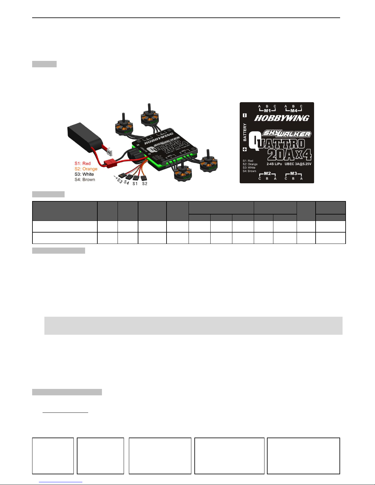
1. 4 speed controllers in1board, only 1 pair of battery wire is needed.
2. Powerful switch mode built-in BEC (the BEC voltage outputs from the S3 connector).
3. Multiple protection features: Low voltage cut-off protection / over-heat protection / throttle signal loss protection.
4. The throttle range of each ESC can be calibrated to be suitable for different multi-rotor flying control systems / transmitters.
5. Maximum speed: 210000 RPM (2 poles motor), 70000 RPM (6 poles motor), 35000 RPM (12 poles motor).
Specification
Size
2S Lipo 3S Lipo 4S Lipo Lipo
NiMH L*W*H
Skywalker Quattro
20A*4-UBEC
20A*4 25A*4 Switch mode 5V@3A 5 servos 5 servos 4 servos 2-4S 5-12 cells 112g 70*62*11
Skywalker Quattro
25A*4-UBEC
25A*4 30A*4 Switch mode 5V@3A 5 servos 5 servos 4 servos 2-4S 5-12 cells 112g 70*62*11
Weight
Battery Cell
Model
Cont.
Current
Burst
Current
(>10s)
BEC
Mode
BEC
Output
BEC Output Capability
Programmable Items (The option written in bold font is the default setting)
1. Brake:Disabled / Enabled
2. Battery Type:Lipo / NiMH
3. Low Voltage Protection Mode (Cut-Off Mode): Soft Cut-Off (Gradually reduce the output) /Cut-Off (Immediately stop the output)
4. Low Voltage Protection Threshold (Cut-Off Threshold):Low / Medium / High
a) For lithium battery, the battery cell amount is calculated automatically. Low / medium / high cutoff voltage for each cell is:
2.85V/3.15V/3.3V. For example: For a 3S Lipo battery, when “Medium” cutoff threshold is set, the cut-off voltage will be:
3.15*3=9.45V
b) For NiMH battery, low / medium / high cutoff voltages are 0% / 50% / 65% of the startup voltage (i.e. the initial voltage of
battery pack), and 0% means the low voltage cut-off function is disabled. For example: For a 6 cells NiMH battery, fully
charged voltage is 1.44*6=8.64V, when “Medium” cut-off threshold is set, the cut-off voltage will be 8.64*50%=4.32V。
Warning! In order to protect the expensive multi-rotor, the default settings (i.e. Battery Type = “NiMH” and Cut-Off Threshold =
“Low”) don’t take any protection even if the Lipo battery is over discharged. If you do need to activate the battery protection function
please change the default settings.
5. Startup Mode:Normal /Soft /Super-Soft (300ms / 1.5s / 3s)
The initial acceleration of the Soft and Super-Soft modes are slower than the Normal mode, it takes 1.5 second for Soft startup or 3
seconds for Super-Soft startup from initial throttle advance to full throttle. If the throttle is completely closed (throttle stick moved to
bottom position) and opened again (throttle stick moved to top position) within 3 seconds after the first startup, the re-startup will be
temporarily changed to normal mode to get rid of the chance of a crash caused by slow throttle response. This special design is
suitable for aerobatic flight when quick throttle response is needed.
6. Timing:Low / Medium / High,( 3.75°/ 15°/ 26.25°)
Usually, the default timing is suitable for most motors. To get higher speed, High timing can be chosen.
Begin To Use Your New ESC
Because different transmitters / flying control systems have different throttle ranges, please calibrate the throttle range for each speed
controller before flying.
The Throttle Signal HUB is recommended for calibrating the throttle ranges for 4 speed controllers simultaneously instead of one by one.
Throttle range setting:
Note: The throttle range of each speed controller in the Quattro should be set separately. When the Quattro is installed in a multi-rotor,
you should set the throttle range of each ESC via the flying control system.
Switch on the
transmitter,
move throttle
stick to the
top position
Connect battery
pack to the
ESC, and wait
for about 2
seconds
The “Beep-Beep-” tone
should be emitted,
means the top point of
throttle range has been
confirmed
Move throttle stick to the
bottom position, several
“beep-” tones should be
emitted to present the
amount of battery cells
A long “Beep-” tone should
be emitted, means the
lowest point of throttle
range has been correctly
confirmed
Page 2
Manual of Brushless Motor Speed Controller HW-SM006ENG-20130311 Page 2 of 3
-
Normal startup procedure:
Protection Function
1. Start up failure protection: If the motor failed to start within 2 seconds of throttle application, the ESC would cut-off the output power.
In such a case, the throttle stick MUST be moved to the bottom position again to restart the motor. (Such a situation happens in the
following cases: The connection between ESC and motor is not reliable, the propeller or the motor is blocked, etc.)
2. Over-heat protection: When the temperature of the ESC is higher than 110 Celsius degrees, the ESC will reduce the output power.
3. Throttle signal loss protection: The ESC will reduce the output power if the throttle signal is lost for 1 second, further loss for 2
seconds will cause the output to be cut-off completely.
Trouble Shooting
Trouble
Possible Reason
Action
After power on, motor doesn’t work, no
sound is emitted
The connection between battery
pack and ESC is not correct
Check the power connection.
Replace the connector.
After power on, motor doesn’t work, such
an alert tone is emitted:
“beep-beep-, beep-beep-,beep-beep-”
(Every “beep-beep-” has a time interval
of about 1 second)
Input voltage is abnormal, too high
or too low.
Check the voltage of battery pack
After power on, motor doesn’t work, such
an alert tone is emitted:
“beep-, beep-, beep- ”(Every “beep-” has
a time interval of about 2 seconds)
Throttle signal is abnormal.
Check the receiver / transmitter / flying controller
Check the cable of throttle channel
After power on, motor doesn’t work, such
an alert tone is emitted:
“beep-, beep-, beep-” (Every “beep-” has
a time interval of about 0.25 second)
The throttle stick is not in the
bottom (lowest) position
Move the throttle stick to bottom position
After power on, motor doesn’t work, a
special tone “ ” is emitted after 2
beep tone (beep-beep-)
The Direction of throttle channel is
reversed, so the ESC enters the
program mode
Set the direction of throttle channel correctly
The motor runs in the opposite direction
The connection between ESC and
the motor need to be changed.
Swap any two wire connections between ESC and
motor
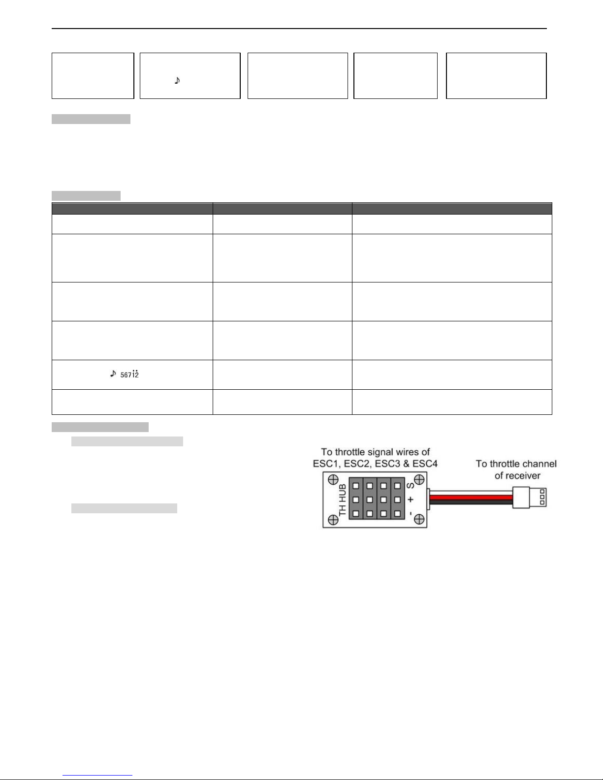
Accessory: Throttle Hub (Throttle Hub is a standard accessory for Quatrro ESC)
1.
Applications of Throttle Hub
a) Use this throttle Hub to calibrate the throttle range for the
Quattro ESC ( The Quattro is an equipment in
quadcopter, usually it has 4 ESCs in 1 board);
b) Use this throttle Hub as throttle signal distributor for
several speed controllers (1 ESC to 4 ESCs).
2.
Operations of Throttle Hub
a) To calibrate the throttle range for the Quattro ESC
Plug the throttle signal wires of 4 ESCs (S1 to
S4) into Port #1 to Port #4 of the throttle Hub.
Attention!
In the following picture, the pins at the symbol “S” line are the paths of throttle signals
transmission.
Plug the lead at right side into the throttle channel of receiver or fly-control system.
Connect battery to the Quattro ESC.
Calibrate throttle range of the 4 ESCs in the Quattro simultaneously.
b) To distribute throttle signal to several ESCs
Generally, in case of throttle signal distribution, only one ESC has its built-in BEC enabled (or reserved), the
BECs in other ESCs must be disabled (That is, cut the red wires in the Rx cables)
Plug the throttle signal wires of 4 ESCs into Port #1 to Port #4 of the throttle Hub.
Attention!
In the following picture, the pins at the symbol “S” line are the paths of throttle signals
transmission.
Plug the lead at right side into the throttle channel of receiver.
Move throttle stick
to bottom position
and then switch
on transmitter.
Connect battery pack
to ESC, special tone
like “ 123” means
power supply is OK
When self-test is
finished, a long
“beep-----” tone
should be emitted
Move throttle stick
upwards to go flying
Several “beep-” tones
should be emitted to
present the amount of
lithium battery cells
Page 3

Manual of Brushless Motor Speed Controller HW-SM006ENG-20130311 Page 3 of 3
-
Program ESC With Transmitter (4 Steps)
NOTE:
1. Each speed controller in the Quattro must be programmed separately.
2. Please make sure the settings for each speed controller in the Quattro are same.
1. Enter program mode
1) Switch on transmitter, move throttle stick to top
position, connect the battery pack to ESC
2) Wait for 2 seconds, the motor should emit
special tone like “beep-beep-”
3) Wait for another 5 seconds, special tone like
“ ” should be emitted, which means
program mode is entered
4. Exit program mode
There are 2 ways to exit
program mode:
1. In step 3, after special
tone “ ”, please
move throttle stick to
the bottom position
within 2 seconds.
2. In step 2, after tone
“beep-----beep-----”(ie.
The item #8), move
throttle stick to bottom
within 3 seconds.
3. Select option (Programmable value):
You will hear several tones in loop. Set the value matching to a tone by moving throttle stick
to top when you hear the tone, then a special tone “ ” emits, means the value is set
and saved. (Keeping the throttle stick at top, you will go back to Step 2 and you can select
other items; or moving the stick to bottom within 2 seconds will exit program mode directly)
Tones
Items
“beep-”
1 short tone
“beep-beep-”
2 short tones
“beep-beep-beep”
3 short tones
Brake
Off
On
Battery type
Lipo
NiMH
Cutoff mode
Soft-Cut
Cut-Off
Cutoff threshold
Low
Medium
High
Start mode
Normal
Soft
Super soft
Timing
Low
Medium
High
2. Select programmable items:
After entering program mode, you will hear 8 tones in a loop with
the following sequence. If you move the throttle stick to bottom
within 3 seconds after one kind of tones, this item will be selected.
1. “beep” brake (1 short tone)
2. “beep-beep-” battery type (2 short tone)
3. “beep-beep-beep-” cutoff mode (3 short tone)
4. “beep-beep-beep-beep-” cutoff threshold (4 short tone)
5. “beep-----” startup mode (1 long tone)
6. “beep-----beep-” timing (1 long 1 short)
7. “beep-----beep-beep-” set all to default (1 long 2 short)
8. “beep-----beep-----” exit (2 long tone)
Note: 1 long “beep-----” = 5 short “beep-”
Note: Please make sure the throttle volume is set
to 0 when the throttle stick is moved to the bottom
position and 100% at the top position
1. Enter program mode
2. Select programmable items
3. Select options (Programmable value)
4. Exit program mod
 Loading...