

Page 1
Auto-Darkening Welding Helmet
XT Series
Models: XTF/XTV/XTP
OM-221 534C
2006−03
Page 2

Table Of Contents
SECTION 1 − SAFETY PRECAUTIONS −
READ BEFORE USING 1. . . . . . . . . . . . . . . . . . . .
SECTION 2 − SPECIFICATIONS 2. . . . . . . . . . . . . . . . . . . . . . . .
SECTION 3 − OPERATING INSTRUCTIONS 5. . . . . . . . . . . . . .
SECTION 4 − BATTERY REPLACEMENT 8. . . . . . . . . . . . . . . .
SECTION 5 − MAINTENANCE 8. . . . . . . . . . . . . . . . . . . . . . . . . .
SECTION 6 − TROUBLESHOOTING 9. . . . . . . . . . . . . . . . . . . . .
SECTION 7 − LIMITED WARRANTY 10. . . . . . . . . . . . . . . . . . . . .
SECTION 8 − REPLACEMENT PARTS 11. . . . . . . . . . . . . . . . . . .
Page 3
Page 1
SECTION 1 − SAFETY PRECAUTIONS −
READ BEFORE USING
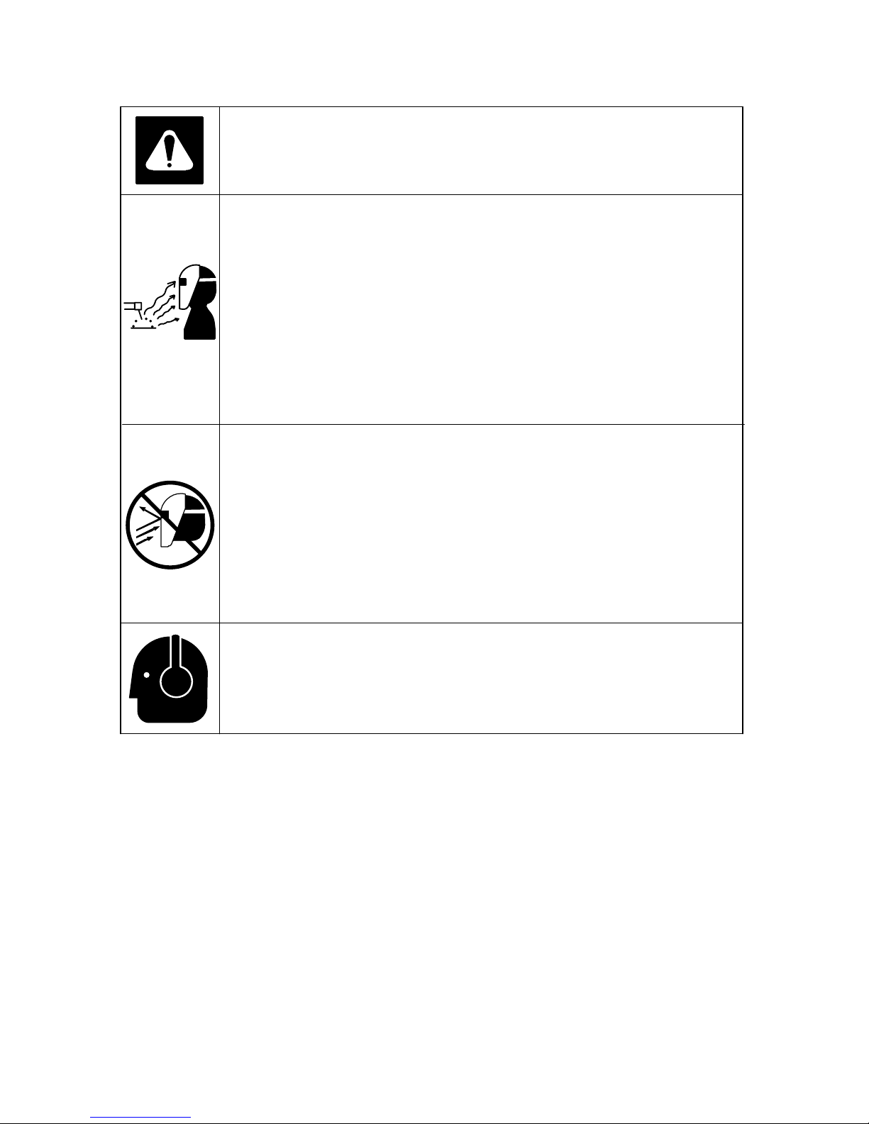
Warning! Watch Out! There are possible hazards as shown
in the adjoining symbols.
D Read and follow Section 1 for all safety symbols.
ARC RAYS can burn eyes and skin.
Arc rays from the welding process produce intense visible and invisible (ultraviolet and infrared) rays that can burn eyes and skin. Sparks fly off from the weld.
D Wear a welding helmet fitted with a proper shade of filter to protect your
face and eyes when welding or watching (see ANSI Z49.1 and Z87.1 listed
in Safety Standards). Refer to Shade and Sensitivity charts in Section 2.
D Wear approved safety glasses with side shields under your helmet.
D Use protective screens or barriers to protect others from flash and glare;
warn others not to watch the arc.
D Wear protective clothing made from durable, flame-resistant material
(leather and wool) and foot protection.
WELDING HELMETS do not provide unlimited eye, ear and
face protection.
D Use impact resistant safety spectacles or goggles and ear protection at all
times when using this welding helmet.
D Do not use this helmet while performing grinding operations, working with
or around explosives or corrosive liquids.
D Do not weld in the overhead position while using this helmet.
D Inspect the auto-lens frequently. Immediately replace any scratched,
cracked, or pitted cover lenses or auto-lenses.
NOISE can damage hearing.
Noise from some processes or equipment can damage hearing.
D Wear approved ear protection if noise level is high.
Page 4

Page 2
SECTION 2 − SPECIFICATIONS
XTF Technical Specifications (Fixed Shade #10)
Cartridge Dimensions 4.33 x 3.54 x 0.39 in (110 x 90 x 10 mm)
Viewing Field 3.75 x 1.37 in (95 x 35 mm)
Reaction Time Light to dark: 0.00028 second (1/3,600)
Dark to light: 0.12 second
Available Shades Darkened State: #10 / Light State: #3
Sensors Independent (Two)
Operating Temperature 23_F to 131_F (−5_C to +55_C)
Storage Temperature −4_F to 176_F (−20_C to +80_C)
Power Supply Battery-powered, solar rechargeable
(internal, non-replaceable lithium battery)
Total Weight 1 lb (454g)
Standards ANSI Z87.1-2003/CSA
Warranty 2 years from date of purchase (see Section 7)
Lens
NOTE: Expose the solar cell to bright sunlight for 30 minutes before use.
Page 5
Page 3
XTV Technical Specifications (#9 − #12 Variable Shade)
Cartridge Dimensions 4.33 x 3.54 x 0.39 in (110 x 90 x 10 mm)
Viewing Field 3.75 x 1.57 in (95 x 40 mm)
Reaction Time 0.000083 second (1/12,000)
Available Shades ANSI: Darkened State: #9 − 12 / Light State: #4
CE/CSA: Darkened State: #9 − 13 / Light State: #4
Sensors Independent/redundant (Two)
Operating Temperature 23_F to 131_F (−5_C to +55_C)
Storage Temperature −14_F to 158_F (−10_C to +70_C)
Power Supply 2 AAA Alkaline batteries (included)
Total Weight 1 lb (454g)
Standards ANSI Z87.1-2003 CE/CSA
Warranty 2 years from date of purchase (see Section 7)
Sensitivity Control light levels Adjusts for varying ambient light and welding arc
Delay Control Slows lens dark-to-light state between 0.1 and
0.5 seconds (fast/slow switch)
Automatic Power Off Shuts lens off 15−20 minutes after last arc is struck
Low Battery Indicator Red LED light illuminates to indicate low battery
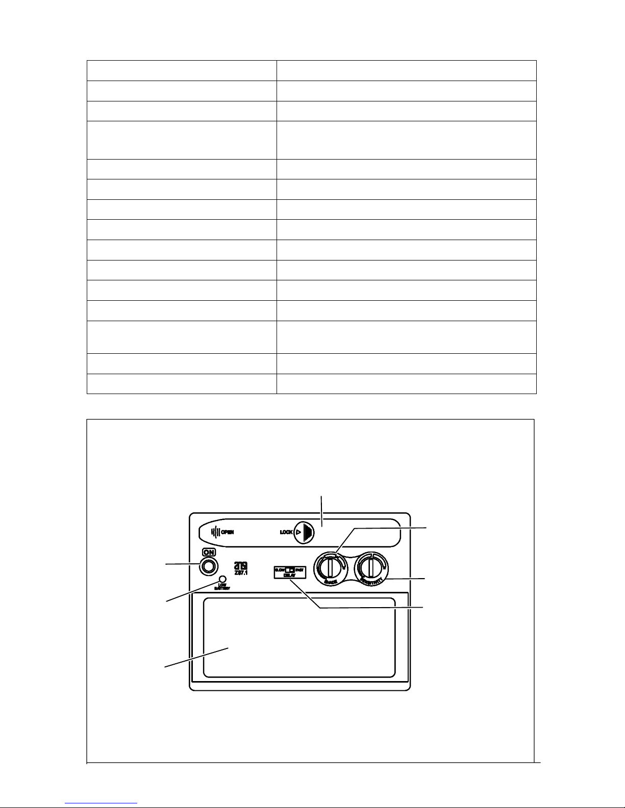
Battery Compartment
(2 AAA Alkaline Batteries Included)
Shade Control
Sensitivity Control
Delay Control
Lens
Low Battery
Indicator
On/Off Button
Page 6

Page 4
XTP Technical Specifications (Professional #9 − #13 Variable Shade)
Cartridge Dimensions 4.33 x 3.54 x 0.39 in (110 x 90 x 10 mm)
Viewing Field 3.81 x 1.85 in (97 x 47 mm)
Reaction Time 0.0000625 second (1/16,000)
Available Shades Darkened State: #9 − 13 / Light State: #4
Sensors Independent/redundant (Two)
Operating Temperature 140_F to 1310_F (60_C to +710_C)
Storage Temperature −40_F to 1580_F (−40_C to +860_C)
Power Supply CR2450 Lithium battery (Hobart 770284)
Total Weight 1 lb (454g)
Standards ANSI Z87.1-2003/DIN/CE/TUV/CSA
Warranty 2 years from date of purchase (see Section 7)
Sensitivity Control light levels Adjusts for varying ambient light and welding arc
Delay Control Slows lens dark-to-light state between 0.1 and
1.0 seconds (infinite dial control)
Automatic Power Off Shuts lens Off 15−20 minutes after last arc is struck
Low Battery Indicator Red LED light illuminates to indicate low battery
Battery
Compartment
(Lithium
Battery Included)
Shade Control
Sensitivity Control
Delay Control
Lens
Low Battery
Indicator
On/Off Button
Page 7

Page 5
SECTION 3 − OPERATING INSTRUCTIONS
On/Auto-Off Button
Locate the ON button and press ON to weld. The lens will automatically
darken twice and then return to the light state. The helmet is then ready
to weld.
Note: The lens will Auto-Off (clear state − #4) 15−20 minutes after the last
arc. It will be necessary to press the ON button to resume welding.
Note: The XTF model has no On/Auto-Off button; the helmet turns on automatically.
Variable Shade Control
Model XTF − Fixed Shade #10
Model XTV − Variable Shade #9 − #12
Model XTP − Variable Shade #9 − #13
Use the shade chart below to select proper shade control setting based
on your welding process. We recommend starting at shades 12 or 13 and
adjust lighter based on the welding application and personal preference.
Application Welding Arc Current in Amperes Protective Shade No.
Stick Electrodes Less than 40
40−80
80−175
175−300
#9
#10
#11
#12 − #13
MIG Less than 100
100−175
175−300
#10
#11
#12 − #13
Gas Tungsten Arc Welding
(TIG)
Less than 50
50−100
100−200
200−300
#10
#11
#12
#13
Page 8

Page 6
Sensitivity Control (XTV And XTP Models Only)
The sensitivity control is used to make the lens more responsive to differing light levels experienced in various welding processes. We recom-
mend a (Mid-Range or 30−50%) sensitivity setting for most applica-
tions. Please refer to the chart below for recommended settings.
Recommended Sensitivity Settings
Stick Electrode Mid-Range
Short Circuiting (MIG) Low/Mid-Range
Gas Tungsten Arc (TIG) Mid/High-Range
Plasma Arc Cutting/Welding Low/Mid-Range
Helpful Hint For Setting Sensitivity In Low Amperage Tig, 50
Amps And Below:
1. Face the helmet front toward the floor.
2. Turn the sensitivity setting toward HI until the lens darkens.
3. Now, reduce the sensitivity by turning the control to the left until the
lens lightens; you are then ready to weld.
4. When job is completed, return sensitivity control to mid-range.
Lens Delay Control
The lens delay control is used to slow the lens-switching time to the clear
state after welding. The delay is particularly useful in eliminating bright
after-rays present in higher amperage applications where the molten
puddle remains bright momentarily after welding.
Low Battery Indicator
The low battery indicator lights when 2−3 days of battery life remain (see
battery recommendations below).
Model XTF: Non-replaceable Lithium battery.
Model XTV: Replace with 2 AAA Alkaline batteries.
Model XTP: Replace with Lithium battery CR2450.
Page 9

Page 7
Adjustment of the Headgear for Maximum Comfort
There are four adjustments on Hobart headgear that can be adjusted for
maximum comfort:
1. Headgear Top – Adjusts headgear for proper depth on the head to ensure correct balance and stability.
2. Headgear tightness – To adjust, turn knob located on the back of the
headgear left or right to desired tightness.
3. Stop angle adjustment – Five pins on the right side of the headband top
provide adjustment for the forward tilt of the helmet. To adjust, loosen the
right outside tension adjustment knob and lift on the control arm tab to
move it to the desired position. Retighten tension adjustment knob.
4. Distance adjustment – Adjusts the distance between the face and the
lens. To adjust, loosen both outside tension knobs and slide forward or
back to desired position and retighten. (Both sides must be equally positioned for proper vision.)
Replacement of the Front and Inside Lens Covers
Y Warning! Never use the auto-darkening lens without the inside
and outside lens covers properly installed. Welding spatter will
damage the auto-darkening lens voiding the warranty.
1. Outside − Place helmet on a flat surface. Grasp the front lens holder
with one hand while pushing the inside retaining clips of the lens holder outward. Do one side at a time, gently pulling the front lens holder
away from the helmet as each tab is released from its retaining clip.
Once released, the outside cover lens can be replaced.
2. Inside − Remove the inside lens cover by following the procedure in
Step 1. With the auto-darkening lens removed from the helmet, remove the inside cover lens by prying the lens up at the thumbnail
opening located at the top center of the cover lens. Replace the lens
by gently bowing it in the center and inserting it, one end a time, into
the retaining clips located on the outside of the auto-darkening lens
assembly.
3. Reinstalling auto−darkening lens assembly − Gently place auto−
darkening lens in front of helmet. (Be careful not to drop lens.) Install
front lens cover with gasket. Grasp front lens holder and slowly insert
the six retaining pieces into front of helmet. (Make certain you gently
squeeze the outside edges of the front lens holder while inserting tabs
into helmet.) From the inside of helmet, gently push the retaining tabs
in to secure the front lens holder in place.
Page 10

Page 8
SECTION 4 − BATTERY REPLACEMENT
Model XTV: Remove the batteries by sliding the cover plate to the left. Replace with 2 AAA alkaline batteries. (Note: be sure the positive (+) side
of the battery is aligned with positive (+) terminal.) Replace cover plate
and then press On button.
Model XTP: Remove the batteries by turning the battery cover counterclockwise 90 degrees. Replace with Lithium battery CR2450. (Note: be
sure the battery positive (+) terminal is up.) Replace the cover and then
press On button.
NOTE: The XTF model has a non-replaceable Lithium battery.
SECTION 5 − MAINTENANCE
Cleaning
The helmet requires little maintenance, however for best performance we
recommend cleaning after use. Using a soft cloth dampened with a mild
soap and water solution, wipe the cover lenses clean. Allow to air dry.
Occasionally, the filter lens and sensors should be cleaned by gently wiping with a soft, dry cloth. (Never use solvents or abrasive cleaning de-
tergents. Do not immerse the lens assembly in water).
Page 11

Page 9
SECTION 6 − TROUBLESHOOTING
Symptom Solution
Not ON – auto-lens will not darken
momentarily when turned on.
Check batteries and make sure that they are in good
condition and installed properly. Also, check battery
surfaces and contacts and clean if necessary. Check
battery for proper contact and gently adjust contact
points if necessary. This is particularly important if the
helmet may have been dropped.
Not switching – auto-lens stays light
and will not darken when welding.
Stop welding immediately: Make sure the auto-lens
power is turned ON. If power is on, review the sensitivity
recommendations and adjust sensitivity. Clean lens
cover and sensors of any obstructions. Make sure the
sensors are facing the arc, angles of 45_ or more may
not allow the arc light to reach the sensors.
Not Switching – auto-lens stays dark
after the weld arc is extinguished, or
the auto-lens stays dark when no arc
is present.
Fine-tune the sensitivity setting by making small adjustments to the control by turning it toward the “Low” setting. In extreme light conditions, it may be necessary to
reduce the surrounding light levels.
Sections of the auto-lens are not going dark, distinct lines separate the
light and dark areas.
Stop welding immediately: The auto-lens may be
cracked which can be caused by the impact of dropping
the helmet. Weld spatter on the auto lens may also
cause cracking. (The lens may need to be replaced,
most cracked lenses are not covered by warranty).
Switching or Flickering – the autolens darkens then lightens while the
welding arc is present.
Review the sensitivity setting recommendations and
increase the sensitivity if possible. Make sure that the
arc sensors are not being blocked from direct access to
the arc light. Check the lens cover for dirt and spatter
that may be blocking the arc sensors.
Inconsistent or lighter auto-lens
shading in the dark-state, noticeable
on the outside edges and corners.
Referred to as an angle of view effect, auto-darkening
lenses have an optimum viewing angle, perpendicular,
90_ to the surface of the auto-lens. When that angle of
view varies in the dark-state, welders may notice slightly
lighter areas at the outside edges and the corners of the
lens. This is normal and does not represent any health
or safety hazard. This effect may also be more noticeable in applications where magnifying lenses are used.
Page 12

Page 10
SECTION 7 − LIMITED WARRANTY
Effective December 1, 2005
LIMITED WARRANTY – Subject to the terms and conditions below. Hobart Welding
Retail, Appleton, Wisconsin, warrants to its original retail purchaser that the new Hobart equipment sold after the effective date of this limited warranty is free of defects
in material and workmanship at the time it is purchased at the retailer. THIS WARRANTY IS EXPRESSLY IN LIEU OF ALL OTHER WARRANTIES, EXPRESS OR
IMPLIED, INCLUDING THE WARRANTIES OR MERCHANTABILITY AND FITNESS.
Hobart auto-darkening lens helmets are warranted for two (2) years from the date
of purchase. Proof of purchase is required for warranty transactions so it is
imperative that a copy of the original invoice or sales receipt be retained.
For warranty transactions, contact your original Hobart retailer.
Page 13

Page 11
SECTION 8 − REPLACEMENT PARTS
Item No. Description Stock No.
1* Kit, Lens Cover Flat Black 770425
Kit, Lens Cover Gloss Black 770426
Kit, Lens Cover Patriot (Blue) 770452
Kit, Lens Cover Red Rivet 770453
Kit, Lens Cover Blaze Orange 770454
2 Replacement XTF Lens 770455
Replacement XTV Lens 770427
Replacement XTP Lens 770238
3 Ratchet Headgear Assembly 770433
4 Magnifying Welding Lens 150X 770274
Magnifying Welding Lens 175X 770275
Magnifying Welding Lens 200X 770276
Magnifying Welding Lens 250X 770277
* Kit includes: Bezel, 1 front lens cover gasket, 5 front lens covers, 2 inside lens covers.
803 935
1
2
3
4
Page 14

Page 15

Page 16

PRINTED IN USA © 2006 Hobart Welders
Hobart Welders
1635 West Spencer Street
Appleton, WI 54914 USA
Phone: 800-332-3281
Visit our website at
www.HobartWelders.com
 Loading...