

Page 1

WS SERIES
I
N
S
T
R
U
C
T
I
O
N
S
WASTE EQUIPMENT SYSTEMS
MODEL L-R OPERATION R-L OPERATION
WS800 ML-110368 ML-110369
WS1000 ML-110370 ML-110371
701 S. RIDGE AVENUE
TROY, OH 45374-0001
FORM 19462 Rev. A (5-97)
Page 2

–2–
Page 3

Installation, Operation, and Care of
WS SERIES
WASTE EQUIPMENT SYSTEMS
SAVE THESE INSTRUCTIONS
GENERAL
The WS Series Waste Equipment System is comprised of a pulper, piping, and a water press. The
pulper uses a 5 horsepower motor, stainless steel components, and carbide cutting edges to shred
grindable waste to a pumpable slurry. The slurry flows through the piping to the water press where a
stainless steel screw squeezes out the moisture, compacts the waste, and lifts the semi-dry pulp to the
discharge chute — reducing the original volume significantly. Process water is recycled to the pulper.
WS Series Waste Equipment Systems are self-contained, the pulper and water press are connected
and adjacent to each other. Both models WS800 and WS1000 are available for either left-to-right or
right-to-left operation.
Additional flexibility allows the pulper to be installed undercounter with a water-tight trough connection;
a silver-saver sink (by others) with lift-out basket can be installed with the trough.
INSTALLATION
Prior to installation, test the electrical service to assure that it agrees with the specifications on the
machine data plate located on the front of the water press.
UNPACKING
Immediately after unpacking, check for possible shipping damage. If the unit is found to be damaged,
save the packaging material and contact the carrier within 15 days of delivery.
LOCATION
Locate the water press near a floor drain; floor should be pitched a minimum of
drain. A suitable amount of space should be provided for machine operation, cleaning, and service.
LEVELING
Vibration pads (standard — Fig. 1) must be installed under each leg of the
pulper and water press before making connections. Level the units by
threading the adjustable feet up or down as necessary. After leveling,
tighten set screw in foot flanges.
1
/4" per foot to the floor
Leg
Adjustable
Foot
Rubber Waffle
Vibration
Isolation Pads
Set Screw
Foot Flange
Bolt
Sole Plate
©
HOBART CORPORATION, 1996
Fig. 1
–3–
Page 4
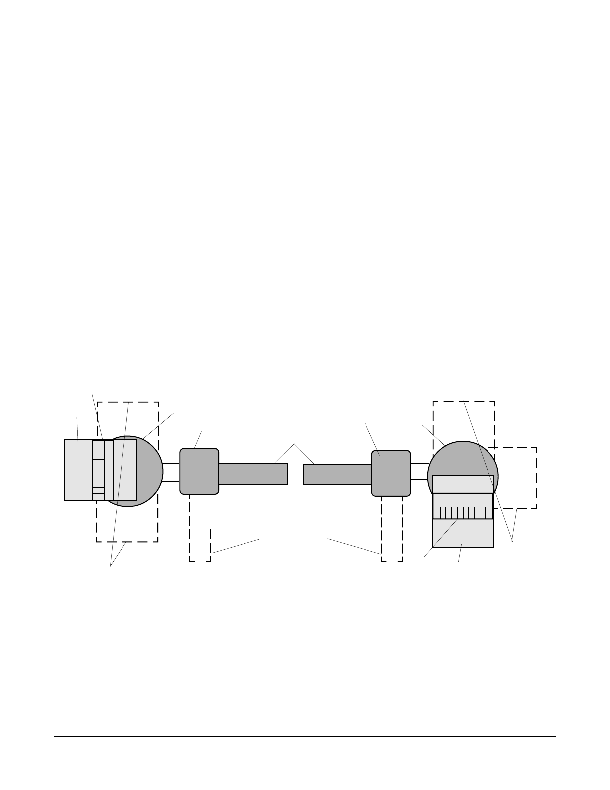
FEED HOOD AND TRAY (Optional)
The feed tray extending from the pulper is available in three lengths: Short (20"), medium (36"
standard), or long (42"). The hood is positioned over the pulper. When the hood is lowered, material
can move from the feed tray to the pulper through the curtains. When the hood is raised, the interlock
shuts off the pulper motor — always wait for the cutting disk to stop rotating before reaching in. The
feed tray and hood can be installed in one of three 90° positions (Fig. 2).
TRAY FLUSH (Optional)
When equipped, the tray flush is attached to the end of the feed tray. The tray flush is plumbed to the
return water line.
DISCHARGE CHUTE
The discharge chute on the water press can be positioned in one of two alternate 90° orientations
(Fig. 2) as specified on the order. Discharge chute is not field rotatable.
Feed
Tray
Alternate
Feed Tray
Positions
Hood
Pulper
Water Press
Discharge Chute
Alternate
Discharge Chute
Position
Fig. 2
Water Press
Right-to-Left OperationLeft-to-Right Operation
Pulper
Hood
Feed
Tray
Alternate
Feed Tray
Positions
–4–
Page 5

UNDERCOUNTER (Optional)
Undercounter models use a feed table (by others) with transition ring (by Hobart) welded underneath
the feed table per instructions (Fig. 3). Install the reed switch packed at the bottom-rear of the water
press to the location indicated (Fig. 3). Undercounter models are provided with a cover plate or a single
opening feed hood, either of which must be placed over the pulper opening of the feed table.
If equipped with cover plate, rotate cover plate so magnet aligns with reed switch — the cover plate
will drop flush into the feed table opening.
If equipped with the single opening feed hood, the magnet is factory installed in the location opposite
the feed opening. This location is appropriate only if the feed opening is oriented 180° from the water
press. If the feed opening is positioned at either 90° orientation, relocate the magnet assembly so it
aligns with the reed switch. The single opening feed hood drops into the table opening so it is level
and the magnet operates the reed switch.
The magnet and reed switch will always be located next to the water press.
UNDERCOUNTER ORIENTATIONS
Fig. 3
–5–
Page 6

CHEMICAL FEEDER (Optional by Others)
If installing a chemical feeder (by others) connect the tube provided (when specified), located at the
rear of the water press to the outlet of the chemical feeder pump. Refer to the wiring diagram for
connection information. Connection points are available in the remote mounted control box as well as
on the terminal blocks located at the rear of the water press. Match line voltage to machine voltage.
Use suitable wire (not bell wire, lamp cord, etc). Maximum Amps available for chemical feeder pump
connection: 2.4 Amp (200 – 240 Volts); 1.6 Amp (380 – 575 Volts).
PLUMBING CONNECTION
WARNING: PLUMBING CONNECTIONS MUST COMPLY WITH APPLICABLE SANITARY, SAFETY,
AND PLUMBING CODES.
Water Connection
Connect the water supply to the
1
/2" NPT internal-thread connector at the bottom-rear of the water press
with a manual shut-off valve. Incoming water pressure must be between 25 psig and 45 psig flowing.
Drain Connection
The drain at the water press must be plumbed to a suitable drain per local code.
ELECTRICAL CONNECTIONS
WARNING: ELECTRICAL AND GROUNDING CONNECTIONS MUST COMPLY WITH APPLICABLE
PORTIONS OF THE NATIONAL ELECTRICAL CODE AND/OR OTHER LOCAL ELECTRICAL CODES.
WARNING: DISCONNECT ELECTRICAL POWER SUPPLY AND PLACE A TAG AT THE DISCONNECT
SWITCH INDICATING THAT YOU ARE WORKING ON THE CIRCUIT.
Refer to the electrical diagram located on the inside of the control box.
The control box is located remote from the pulper and water press. To facilitate field wiring, terminal
blocks are provided in both the control box (NEMA 12) and at the enclosure located at the rear of the
water press. Conduit and wiring (by others) should be installed according to the electrical diagram.
Remote Start/Stop Junction Box (Optional)
One or more remote junction boxes with Start and Stop switches are available and can be installed in
suitable and convenient locations per local codes and the electrical diagram.
Motor Rotation
The Pulper motor, the Water Press motor, and the Pump motor must be checked for correct rotation
after the machine has filled. Arrows are provided to indicate the correct directions of motor rotation.
To check motor rotation, turn power on. Start and Stop the machine. Observe direction of motors.
If incorrect direction of rotation is observed, DISCONNECT ELECTRICAL POWER SUPPLY.
Interchange two power supply leads to the motor(s) with incorrect rotation. Close electrical access
panels. Reconnect electrical power. Turn machine on momentarily to verify correct motor rotation.
–6–
Page 7

OPERATION
WARNING: THE PULPER COVER AND THE DISCHARGE CHUTE ARE EQUIPPED WITH
INTERLOCK DEVICES. THE PULPER COVER MUST BE IN PLACE, THE DISCHARGE CHUTE LID
MUST BE CLOSED, AND THE DISCHARGE CHUTE MUST BE LOWERED BEFORE THE MACHINE
IS USED.
CONTROLS (Fig. 4)
Main Control Panel Controls with Clean Cycle option
ON
OFF
Fig. 4
START CLEAN
Standard Controls
START STOP
CYCLE
STOP
Power disconnect to the machine may be provided by the building electric system or by turning the
handle of the Main Control Panel OFF.
The operator controls are located on the top of the waterpress.
START Button — Turns ON the water supply and fills the tank; the pulper motor, water press
motor, and recirculating pump come on as soon as the tank is full.
STOP Button — Turns OFF the water supply valve, pulper motor, water press motor, and
recirculating pump.
CLEAN CYCLE (Optional) — Sprays the screen in the water press for a preset amount of time and
then automatically shuts off the machine.
Using the Pulper
1. The feed hood curtains should be in place and the feed hood must be closed (when equipped).
Replace all doors on the waterpress. Close the door on the discharge chute and make sure it
is lowered.
2. The drain valve located at the front of the waterpress must be closed. The water supply valve
must be open. The Main Power switch must be ON.
3. Press the START button. The machine begins filling with water. When the machine has filled
to the proper level, the pulper, water press, and recirculating pump motors start automatically.
Allow an additional 2 minutes after the motors come on before feeding waste. After the motors
have come on, the system is controlled by the START and STOP buttons.
–7–
Page 8

Feeding Waste
Waste material should be fed into the pulper no faster than the machine can process. DO NOT
OVERLOAD PULPER. A good gauge for correct feed rate is to feed waste as fast as possible, provided
the material continues to rotate in the pulping tank. If the rotation or vortex is stopped due to
overfeeding, wait a few minutes until rotation resumes. Production can be improved by mixing the
waste whenever possible. Corrugated boxes, for example, can be mixed with food service waste that
would come from a typical dining area. During normal operation, there should be a strong flow of water
returning to the pulper from the water press. This flow is a clue to the performance of the machine since
a sharp reduction in this flow indicates the pulper is overloaded. If this occurs, stop feeding for a few
minutes until return water resumes its normal flow.
Avoid slugging the machine with greasy swill or overloading the pulper with bread or pastry. Mix these
items with bulky waste such as corrugated boxes. The pulper will always perform better with clean,
cold water. It is good practice to drain the machine of dirty water after every meal cycle.
It is recommended that the discharge receptacle (garbage can) not be taller than the bottom of the
discharge chute. Empty receptacle whenever necessary.
Add corrugated boxes at regular intervals while processing.
Special Feeding Instructions
Some waste materials require special feeding techniques to utilize the equipment most efficiently.
Heavy printed matter, computer cards, bulletins, computer printouts, and catalogs should be fed
gradually to avoid overloading.
If waste material is delivered in large plastic bags, tear open the bag and feed one at a time. Unopened
bags can fill with air and float, hampering machine operation.
DO NOT FEED glass or metal containers; if present in the plastic bags, sort them out. Glass and metal
containers are highly abrasive and accelerate machine wear. It is better to recycle glass or metal
containers using a can or bottle crusher to reduce the volume.
DO NOT FEED rags, mop heads, wooden crates, oyster, or clam shells, or heavy uncooked bones to
the pulper. The waste system cannot efficiently reduce the volume of these items.
Foaming
Waste materials with a glossy finished paper or a high glue content tend to create foam in the pulper
tank. If there is excessive foaming in the pulper, it can interfere with the pulping process. Special antifoaming chemicals and metering pumps to inject the chemicals at a uniform rate are available from
chemical supply companies.
–8–
Page 9

CLEANING
6
3
Cleaning requires only a few minutes daily, but must be done on a regular basis and proper facilities
must be available. NOTE: If daily cleaning schedules are not followed, the machine will become
unsightly and odors will develop. A hose with a good quality, lever-operated nozzle should be
available, preferably with hot water, for clean-up of both the machine and the surrounding area.
Save several boxes of paper trash or corrugated cardboard boxes and send them through the pulper
at the end of the operating period.
If equipped with the Clean Cycle option, press the Clean Cycle button — the system will process the
final load for 15 minutes before it automatically shuts down.
If not equipped with the Clean Cycle option, allow at least ten minutes for the final load of paper or
cardboard trash to be processed through the system. Press the STOP button and wait for the pulper
disk to stop.
WARNING: DISCONNECT ELECTRIC POWER SUPPLY AT MAIN CONTROL BOX; PLACE A TAG
AT THE DISCONNECT SWITCH INDICATING THAT YOU ARE WORKING ON THE CIRCUIT; AND
WAIT FOR THE PULPER DISK TO COME TO A COMPLETE STOP BEFORE PERFORMING ANY
CLEANING PROCEDURES.
Open the feed hood or pulper cover plate and remove materials that may be floating on the water —
use a strainer or skim tool. Open the discharge chute and put the remaining pulp in the waste dumpster.
If equipped with the feed hood / tray option, remove the curtains from the clips on the hood. Open drain
valve and drain the machine. Scoop any loose trash remaining in the pulper into a trash container. Use
a hose and wash the inside of the pulper tank (and feed hood and curtains, if equipped).
Open and remove the trash box (Fig. 5). Empty and clean the trash box. Replace the trash box.
After the inside of the pulper tank, feed hood / tray and trash box have been thoroughly washed down,
remove the three waterpress access doors. Use the hose at high pressure to wash down the interior
of the housing and screen. Flush lightly with the hose.
It is not necessary to dig out the plug of pulp remaining at the top of the waterpress screw. After the
machine has been cleaned, wash down the floor, close the drain valve, and dispose of any material
removed from the trash box. Replace all removed parts.
Hood
Feed Tray
Pulper
Trash Box
Discharge Chute
234567890123456789012
2345
Fig. 5
–9–
Page 10

MAINTENANCE
WARNING: DISCONNECT ELECTRIC POWER SUPPLY AT FUSED DISCONNECT SWITCH AND
PLACE A TAG INDICATING THE CIRCUIT IS BEING WORKED ON BEFORE BEGINNING ANY
MAINTENANCE PROCEDURE.
MOTORS
Motors should be kept free of dirt and ventilation openings must not be restricted.
WATER PRESS DRIVE
The water press drive consists of a close coupled motor and speed reducer. The motor requires no
lubrication maintenance. The gears in the speed reducer run in an oil reservoir that should be checked
every six months by your Hobart service technician to maintain adequate oil level and quality.
–10–
Page 11

TROUBLESHOOTING
Symptom Possible Cause Possible Remedy
Machine
will not start.1.2.
No water or
no water
make-up.
Pulper
jammed.
Water press
jammed.
Circuit breaker tripped at power supply.
Power handle on main control box is Off.
3.
Pulper cover not in proper position.
4.
Discharge chute lid not in proper
5.
position.
6.
Discharge chute not in proper position.
No water or not enough water in
machine.
1.2.Water supply off.
Drain valve open or leaking.
1.2.Pulper overloaded.
Pulping disc jammed with scrap metal or
heavy material.
1.
Discharge chute outlet obstructed.
2.
Hardened plug in water press.
3.
Trash container is full and pulp is
backing up in discharge chute.
1.
Replace fuse or reset circuit breaker.
2.
Push handle On.
3.
Put pulper cover in proper position.
4.
Put discharge chute lid in proper position.
5.
Put discharge chute in proper position.
6.
See "No water or no water make-up".
1.2.Turn water supply on.
Close drain valve. Repair if leaking.
1.2.Turn machine off at main control panel.
Clean out and restart.
Turn machine off at main control panel.
Remove metal or material. If material cannot
be removed, call Service.
1.
Turn machine off at main control panel.
Remove residual pulp.
2.
Remove hardened waste material.
3.
Empty trash container and remove loose
pulp from discharge chute.
Will not
drain or
drains very
slowly.
Excessive
foaming in
water press.
1.
Trash box full.
2.
Pulper full of unpulped material.
3.
Drain hose clogged.
1. Pulping of certain materials, such as
glossy paper, cardboard, and potatoes
will produce large quantities of foam.
1.
Turn machine off at main control panel. Do
not remove trash box. Wear protective glove
and clean out from inside of pulper tank.
2.
Run pulper until pulp has been processed. If
it will not process the material, turn the
machine off and clean out the pulper tank.
3.
Remove clean out plug (installed by
plumber) and use water pressure to
eliminate clog.
1. a. Add defoaming agent.
b. Drain machine and refill with fresh water.
c. Turn pulper off when not feeding
machine.
–11–
Page 12

SERVICE
Contact your local Hobart-authorized service office for any repairs or adjustments needed on this
equipment.
FORM 19462 Rev. A (5-97) PRINTED IN U.S.A.
–12–
 Loading...