

Page 1
HL200
ML-134311
Page 1 - English
Page 33 - French
Page 67 - German
INSTALLATION AND OPERATION MANUAL
MANUEL D’INSTALLATION ET D’UTILISATION
INSTALLATIONS UND BEDIENUNGSANLEITUNG
F-34941 (Oct 2005)
Page 2

English / Contents
Section Page
Safety Information 1.0 4
Safety Guidelines 1.1 4
Warning Symbols 1.2 4
Liability 1.3 5
Foreword 2.0 5
General Information 3.0 5
Caring for our Environment 4.0 5
Packing Material 4.1 5
Disposal of your old appliance 4.2 5
Safety Instructions 5.0 5
Dust Hazard 5.1 6
Never 5.2 6
Always 5.3 6
Attachment Safety Instructions 5.4 7
Using the Mixer 6.0 7
Operating for the First Time 6.1 7
Mixer Component Identification Fig. 1 8
Standard Timer Controls 6.2 9
Recipe Timer Controls 6.2 10
Bowl Placement 6.3 11
Agitator 6.4 11
Prepare for Mixing 6.5 12
Operating Notes 6.6 12
Standard Timer Operation 6.7 12
Recipe Timer Operation 6.7 14
View Recipe 6.7 15
Programming Recipe Timer 6.7 15
Unloading 6.8 17
Guard Wire Cage 6.9 17
Remove and Cleaning the Guard Wire Cage 6.10 18
Re-Fitting the Guard Wire Cage 6.11 18
Mixing Capacity Chart 6.12 19
Agitators and Attachments 6.13 21
2
Page 3

Using the Attachment Facility 6.13.1 22
Splash Cover 6.13.2 22
Bowl Scraper Attachment 6.13.3 22
Cleaning 6.14 22
Cleaning after Use 6.14.1 22
Installation and commissioning 6.15 23
Overall Dimensions Fig. 15 23
Technical Information Table 1 24
Unpacking and Handling 6.16 24
Location 6.17 25
Electrical Installation 6.18 25
Operator Training 6.19 26
Mixer Maintenance 7.0 26
Lubrication 7.1 26
Slideways 7.1.1 26
Planetary Seal 7.1.2 27
Bowl Locking Mechanism 7.1.3 27
Adjustments 7.2 27
Agitator Clearance 7.2.1 27
To Measure the Agitator Clearance 7.2.2 27
Interlock Safety System 7.3 28
Fault Finding 8.0 28
Recommended Spares 9.0 29
Notes 10.0 31
Service Contact Numbers 11.0 32
© Hobart 2005
3
Page 4

1.0 SAFETY INFORMATION.
The procedures and precautions contained in this manual are understood to apply to the machinery
only when it is used in the prescribed manner. If the machinery is used other than in the
recommended manner, the operator will be responsible for his/her own safety and for the safety of
the other persons who may be involved.
The information in this manual has been prepared to assist the operator to understand, maintain,
and operate the mixer. In order to prevent accidents, read, understand and follow all the precautions
and warnings contained in this manual before installation or operating for the first time. This manual
must be studied to obtain a clear understanding of the mixer and its capabilities.
1.1 SAFETY GUIDELINES.
Ensure sufficient precautions are observed during manual handling of the mixer particularly when
moving into position on installation. Reference must be made to manual handling regulations. The
mixer weights are given in Table 1.
• Do not hose or pressure clean this appliance. It is vital to adhere to the cleaning instructions
detailed in section 6 of this manual.
• Do not remove any covers or loosen any fittings whilst the machine is operating.
• Ensure this manual is kept in an easily accessible place for future reference near the mixer.
• All operators must be trained in the safe operation of the mixer and attachments.
• Ensure that the power supply cord has been unplugged before attempting to service or move the
mixer.
• Rotating machinery and electricity are potentially hazardous and may cause injury if sufficient
precautions are not taken prior to operating or servicing the machine.
• Always have your mixer and attachments regularly serviced; at least twice a year, depending on
frequency of use.
• When mixing products that develop dust care must be taken. Mix the ingredients using the STIR
facility until the dust is eliminated.
• Exposure to dust (including flour) may be harmful to health causing rhinitis (running noses),
watering eyes and possibly occupational asthma.
1.2
To identify the safety messages in this manual, the following symbols have been used
WARNING SYMBOLS.
The "Warning" symbol is found primarily where the corresponding information is important
for the safe use of the machinery.
The electrical hazard symbol is used when there are risks of an electrical nature. Prior to
servicing the machinery, always disconnect the power cable from the mains supply.
4
Page 5

1.3 LIABILITY.
Installations and repairs which are not carried out by Authorised technicians or the use of other than
original spare parts, and any technical alterations to the machine, may affect the warranty set out in
the standard conditions of sale.
2.0 FOREWORD.
Hobart reserves the right to alter the design of their products without prior notice. Whilst every effort
is made to ensure this publication reflects the latest design, the Company cannot guarantee full
compliance.
Take pride in your HL200 Mixer - keep it clean and in good mechanical and electrical condition.
3.0 GENERAL INFORMATION.
The information and instructions contained in this manual may not cover all details or variations in
the equipment, nor provide for every eventuality to arise with installation, operation, or maintenance.
If additional information is required, please contact your local Hobart office.
The HL200 Mixer is designed to mix food products as detailed on the specification chart (Section
6.12, page 19).
The Legacy 20-litre mixer is a bench-type mixer which features a SmartTimer™, a manual bowl lift
and a #12 attachment hub as standard equipment. With the use of special agitators, a 12 litre bowl
may be used on the HL200 mixer.
The machine is rated to operate on the electrical supplies shown in Table 1, page 24.
The Mixer is fitted with a "no volt release" safety feature to prevent automatic restarting after a
supply failure or disconnection from the mains. The bowl and the guard are interlocked so that when
either is not in their correct operating positions, the mixer will not work. The standard mixer is
delivered with guard, bowl and agitators.
4.0 CARING FOR OUR ENVIRONMENT.
4.1 PACKAGING MATERIAL.
The pallet and protective packing material have been selected from
materials that are environmentally friendly for disposal or can normally
be recycled. Instead of throwing them away, please ensure they are recycled.
4.2 DISPOSAL OF YOUR OLD APPLIANCE.
Old appliances contain materials that can be recycled. Please contact your local waste collection
centre; scrap merchant or local Hobart office about potential recycling schemes.
5.0 SAFETY INSTRUCTIONS.
A FULLY TRAINED AND COMPETENT PERSON MUST ONLY USE THE ATTACHMENT
AND/OR MIXER.
The following instructions must be observed when using the mixer.
5
Page 6

Note: The mixer must only be used for the purpose it was designed and inline with the supplied
operating instructions.
Only use attachments that comply with CE regulations (CE marked).
5.1 DUST HAZARD.
In order to minimise any dust hazard follow the instructions detailed below.
When mixing ingredients care must be taken to avoid the inhalation of dust particles e.g. flour.
Reference should be made to product supplier's data sheets to ensure adequate
precautions/protections are taken.
Items such as flour must be added in such a manner to avoid dust particles being dispersed into the
local atmosphere.
Carefully slit the bag whilst holding in the lower part of the bowl. When mixing dry ingredient use the
lowest speed to minimise dust emission. Use a splash cover to reduce dust emissions (refer to the
recommended spare parts Section 9, page 30 for the cover part number). Mix the ingredients in the
bowl using the lowest speed until the risk of producing any dust is eliminated.
Fit suitable dust extraction equipment.
5.2 NEVER.
• Operate the mixer or attachments if a fault develops or the mixer is unsafe.
• Wear loose clothing.
• Attempt to reach into the bowl when mixing.
• Access rotating parts.
• Fit the agitator to the mixer without a bowl in place.
• Leave the agitator on machine without the bowl being fitted.
• Operate the mixer with attachments and agitator fitted.
• Use excessive force when operating which could affect the stability of the mixer.
• Operate the mixer if parts are disassembled.
• Over ride the safety switches fitted to the mixer.
• Open the guard to stop machine.
• Use the bowl lift to stop machine.
• Use the mixer in an unsafe condition.
• Clean the mixer with scouring powder or a scouring pad.
• Clean aluminium agitators in dishwashers.
• Inhale mixing ingredient dust particles.
5.3 ALWAYS.
• Use the mixer in a well-lit area.
• Ensure the bowl, agitator, attachment and guard are correctly fitted to the mixer.
• Disconnect the mains electricity supply before cleaning the mixer.
• Clean the mixer daily.
• Remove agitator before using any attachments.
• Stop mixer before adding more ingredients.
• Use the stop button to stop machine.
• Clean the bowl, agitators and attachments after use.
• Clean the mixer using mild soap and water.
6
Page 7

• Service the mixer and attachments at least twice a year depending on the frequency of use.
• Use the mixer as intended and inline with the operating instructions.
• Use the correct reduced size equipment (bowl and agitators).
• Use attachments that are CE approved and CE marked.
5.4 ATTACHMENT SAFETY INSTRUCTIONS.
The following instructions must be observed when using the mixer with attachments. Please also
refer to the safety instructions in Section 5.0, page 5 and the instructions provided with the
attachment. Only CE marked and approved attachments must be used.
ONLY A FULLY TRAINED AND COMPETENT PERSON SHOULD USE THE
ATTACHMENT AND/OR MIXER.
• Do not fit an attachment while the mixer is operating.
• Do not wear loose clothing.
• Do not use the mixer or attachment if a fault develops or the machine is unsafe.
• Do not access rotating parts.
• Do not use excessive force when operating the attachment, which could affect the stability of
the mixer.
• Do not operate the mixer if parts are disassembled.
• Always use the attachment and/or mixer in a well-lit area.
• Always ensure the attachment is operating at the correct speed.
• Always clean the attachments after use and refer to the attachment manufacture's cleaning
instructions.
• Always service your mixer and attachments regularly; at least twice a year depending on the
frequency of use.
6.0 USING THE MIXER.
6.1 OPERATING FOR THE FIRST TIME.
Prior to installation, test the electrical service to assure that it agrees with the
specifications on the machine data plate.
Place the mixer on a suitable sturdy level surface. There should be adequate space around the
mixer for the user to operate the controls and to install and remove bowls.
Holes are located in the base to permanently secure the mixer, although this is not necessary in
normal installations.
This food mixer is only for professional use by suitably trained
persons. Ensure operators have read and understood this manual
and have received adequate training. MOVING AGITATOR IN BOWL,
KEEP HANDS, CLOTHING AND UTENSILS OUT WHILE IN
OPERATION. DO NOT USE WITHOUT INTERLOCKED GUARD.
7
Page 8
The Legacy mixer is equipped with SmartTimer™ controls and a manual bowl lift. Other operating
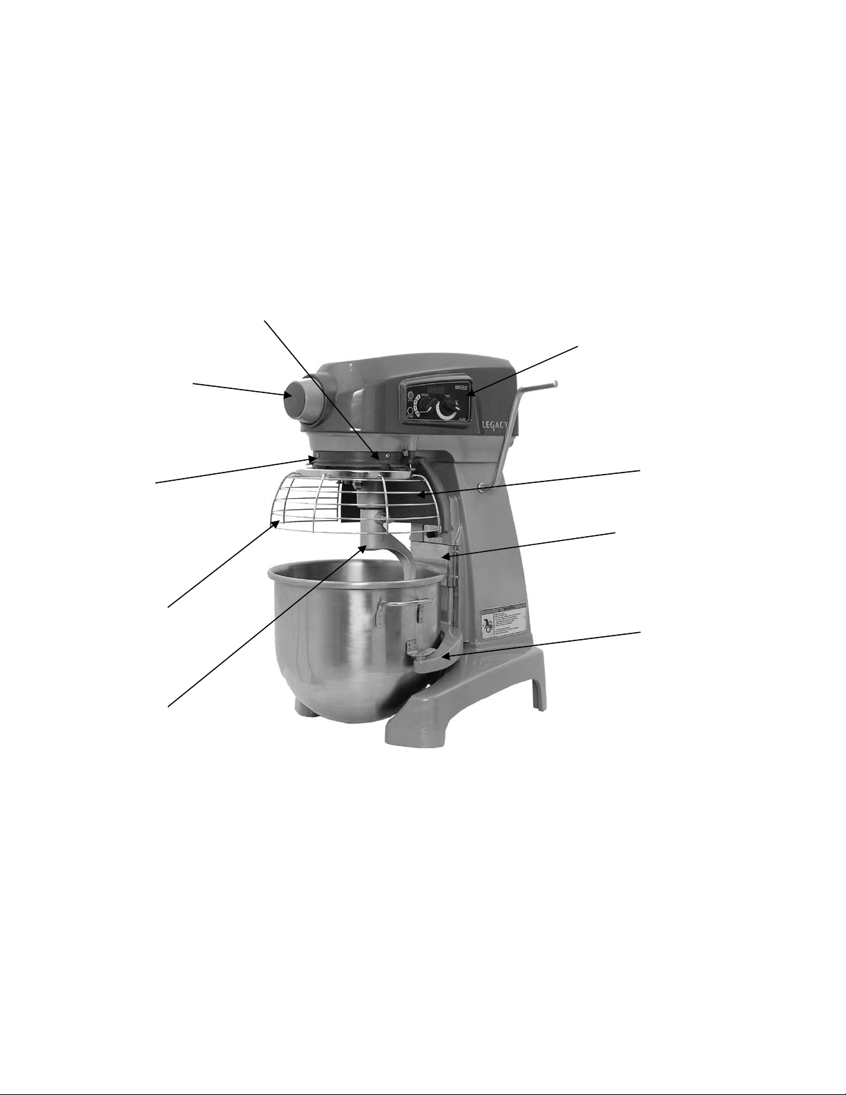
parts (Fig.1) and their functions are described through out the Operation section.
The Guard Wire Cage must be in position or the mixer will not operate.
The bowl must stay in locked position on the Bowl Support or the mixer will not operate.
If the bowl support is not all the way up (mix position), the mixer will not operate.
SLOT
CONTROLS
ATTACHMENT HUB
DRIP CUP
BOWL GUARD
WIRE CAGE
AGITATOR
SPLASH GUARD
APRON
BOWL SUPPORT
Fig. 1.
MIXER COMPONENT IDENTIFICATION
8
Page 9
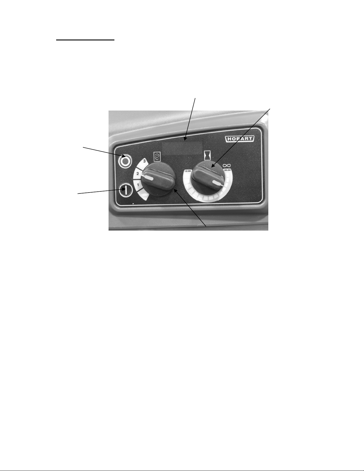
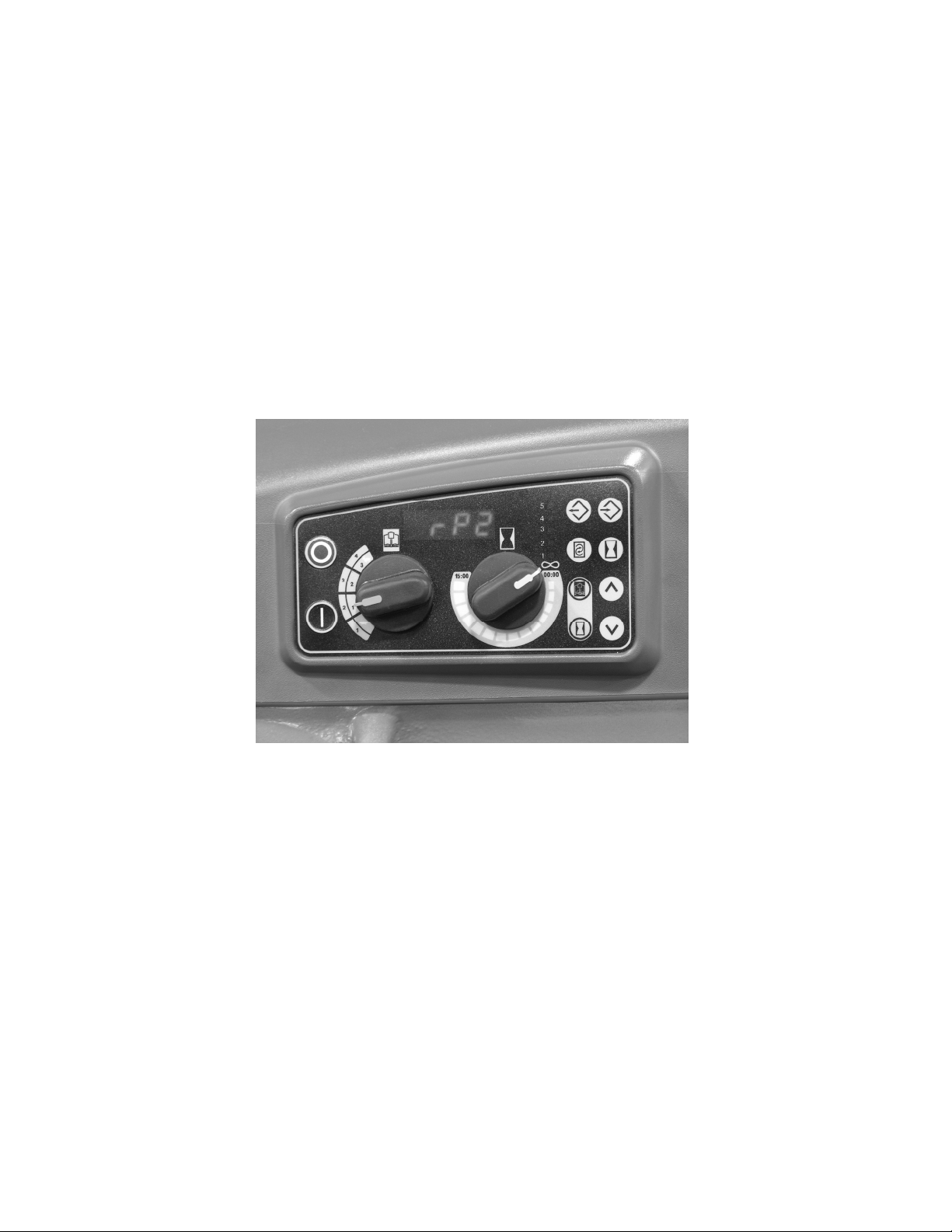
6.2 CONTROLS.
HL200 (With Three Mix Speeds Plus Stir Speed)
DISPLAY
MIXING TIME
STOPS MIXER
STARTS
MIXER
TIME
SELECTOR
SPEED SELECTOR
Fig. 2.
HL200 Mixer Speeds
STIR (Slow) The lowest speed is for incorporating ingredients.
SPEED 1 (Low) This speed is for heavy mixtures such as pizza dough, heavy
batters and potatoes.
SPEED 2 (Medium) This speed is for mixing cake batters, mashing potatoes and developing
bread dough.
SPEED 3 (High) This speed is for incorporating air into light batches, as well as finishing
whipped items.
9
Page 10
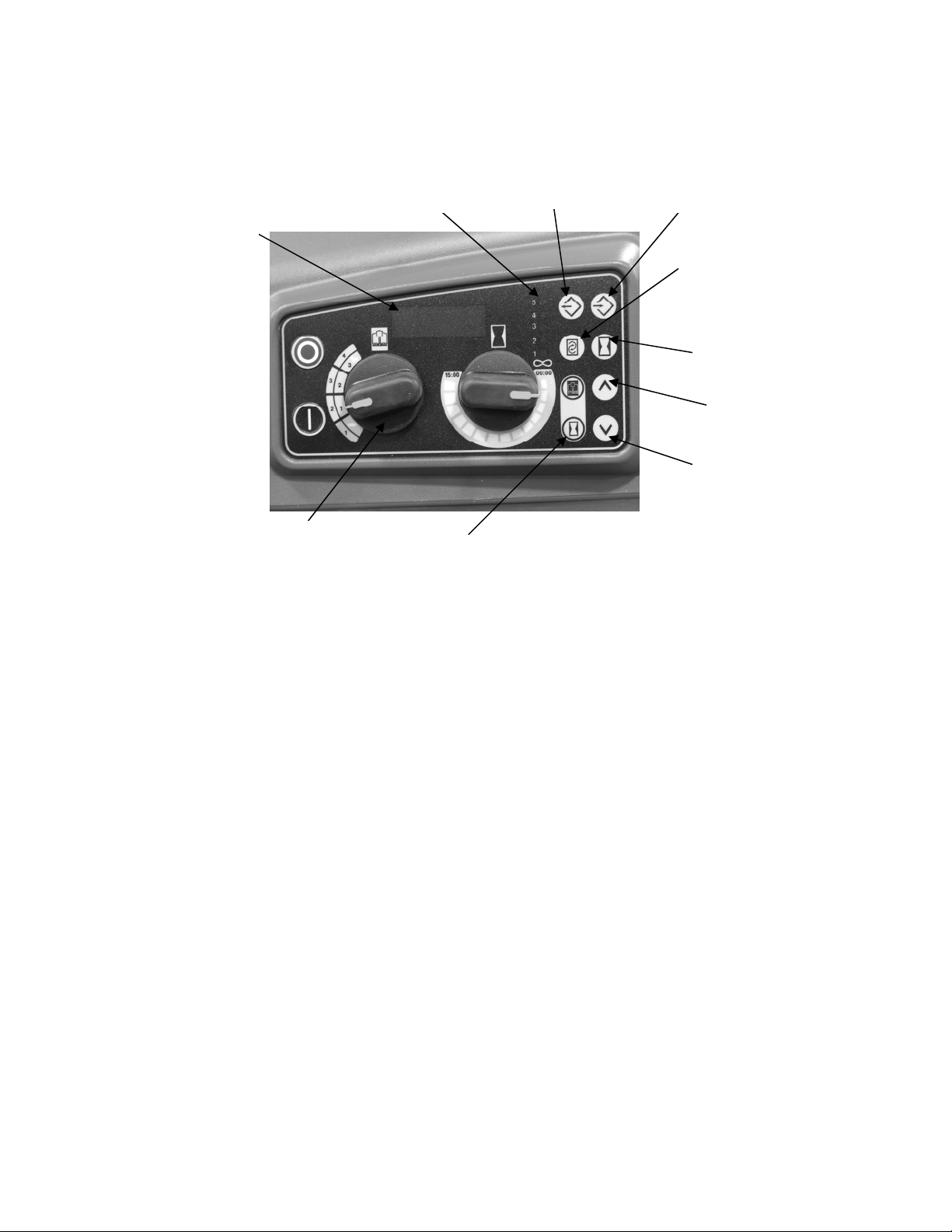
Recipe Timer (Optional)
Model HL200 (With Three Mix Speeds Plus Stir Speed)
DISPLAYS MIXING
TIME OR RECIPE #
RECIPE/SPEED SELECTOR
STEPS IN RECIPE
OPERATING MODE BUTTONS
Fig. 3
PROGRAM
SELECT/SAVE
SPEED
TIME
UP
DOWN
The SmartPlus2™ recipe timer has two operating modes, Standard (STD) and RECIPE.
Standard Mode
Operates exactly as the standard controls utilizing continuous and timed mixing.
Recipe Mode
• Use mode buttons to switch mixer operation between recipe and standard timed operation.
• Up to 4 recipes can be stored in memory.
• Each recipe can contain 5 steps.
• Each step can be programmed to operate with the following speeds and time.
SPEED SETTINGS TIME SETTINGS
SPd 1 (DEFAULT)
SPd 2 End (default)
SPd 3
Stir
PAUS (pause – no mixing)
00:00 – 15:00 minutes (10 second
increments)
10
Page 11
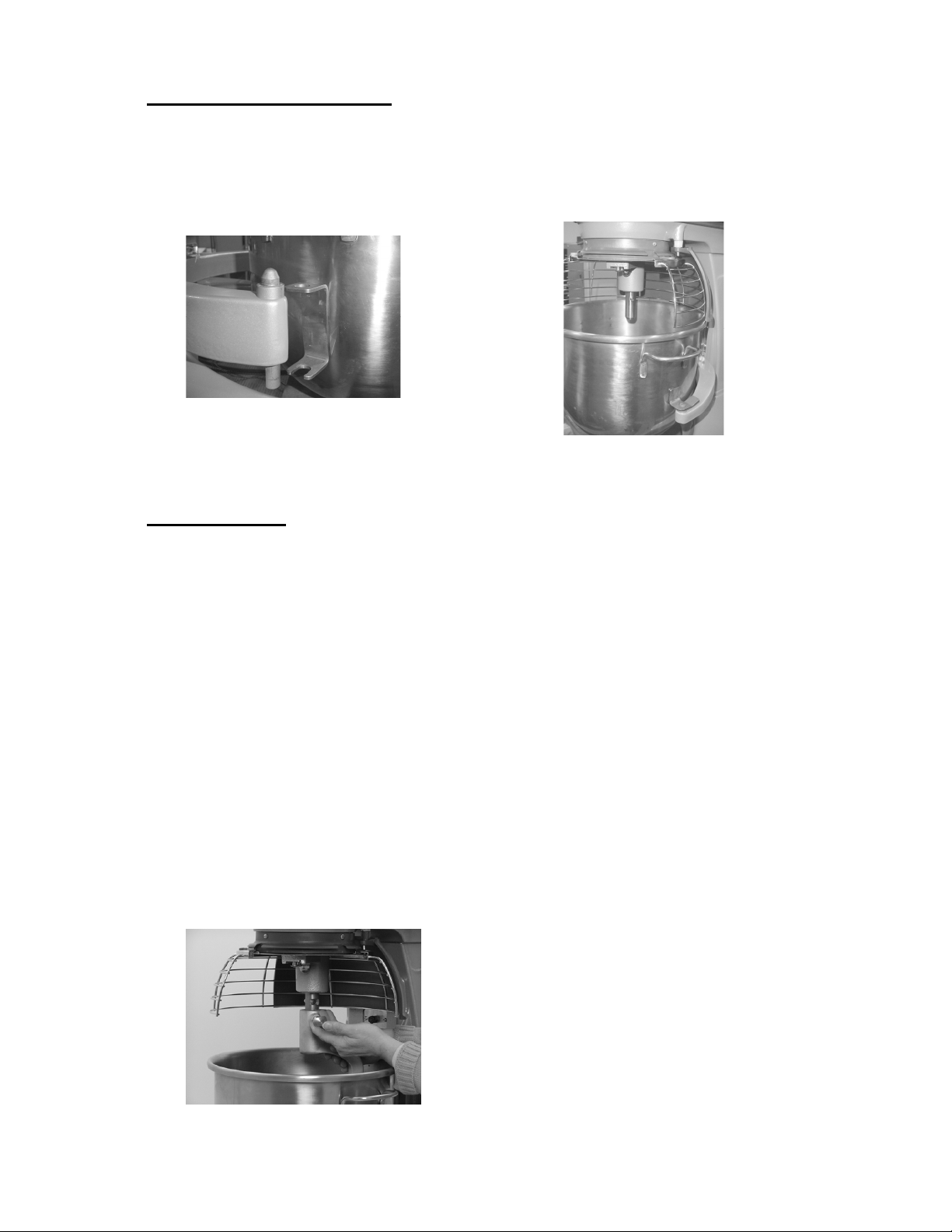
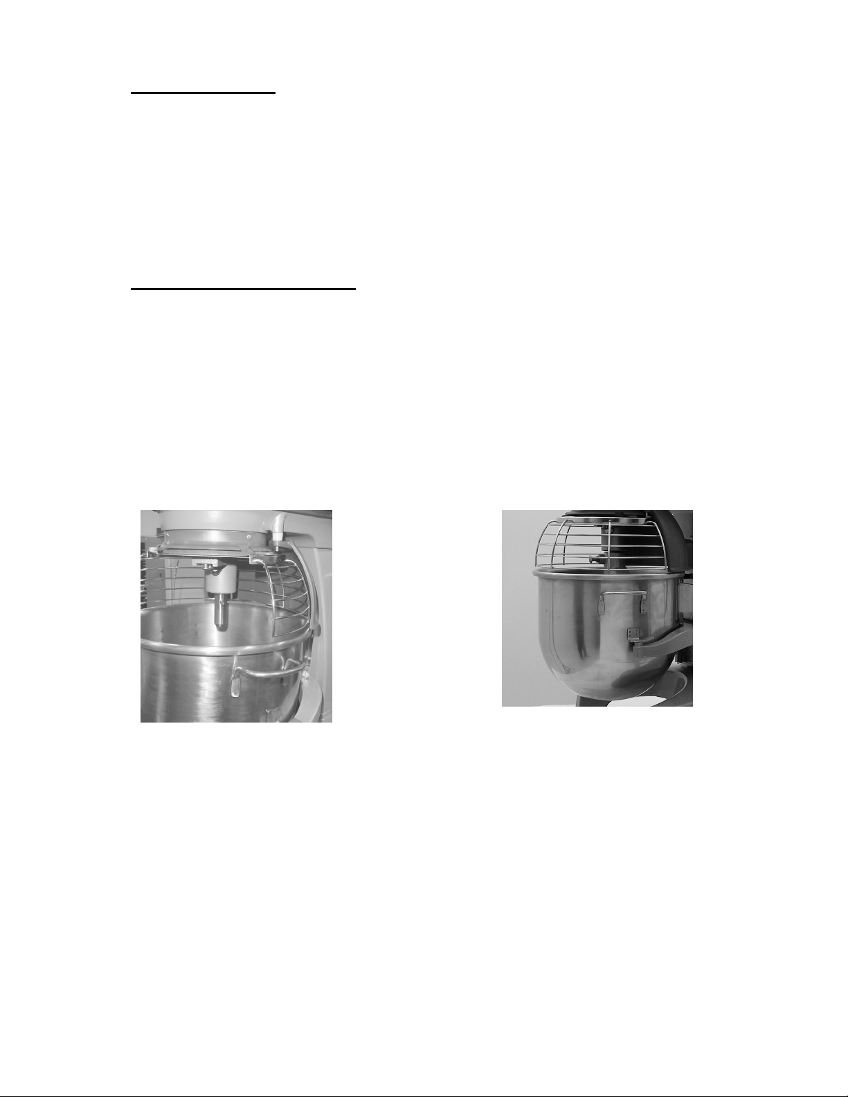
6.3 BOWL PLACEMENT.
The bowl must be installed before the agitator is installed.
To install the bowl, lower the bowl support and position bowl so the alignment pins on the left
side of the bowl support fit in the holes in the bowl tab. (Fig. 4) Place the slotted tab on bowl
into the lower part of the pin. Swing the bowl into the mix position on bowl support. (Fig. 5)
Fig. 4
Fig. 5
6.4 AGITATOR.
To install an agitator, the bowl must be on the bowl support.
To Install
1. Lower the bowl.
2. Open the bowl guard wire cage.
3. Place the agitator inside the bowl and align the horizontal slot on the agitator with the
agitator shaft pin.
4. Slide the agitator up the agitator shaft until it stops and latches. An audible click should
be heard when the agitator locks in position.
To Remove
1. Open the bowl guard wire cage.
2. Lower the bowl.
3. Hold the agitator and pull the plunger of the agitator out (Fig. 6). Slide agitator down off
the agitator shaft.
Fig. 6
11
Page 12
6.5 PREPARE FOR MIXING.
1. Place the mixing bowl on the bowl support.
2. Pour ingredients into the bowl.
3. Swing the bowl back to the mix position.
4. Place the agitator inside the bowl, and then attach it to
the agitator shaft (Fig. 7).
5. Lift bowl support.
6. Correctly close the bowl guard wire cage.
7. The mixer is now ready for mixing. (See TIMER OPERATION.)
Fig. 7
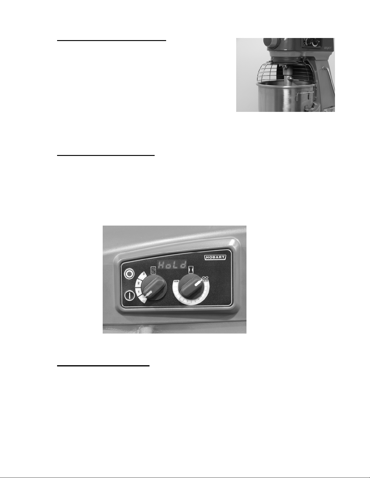
6.6 OPERATING NOTES.
• STIR is to be used for incorporating ingredients. Do not use it to develop dough
products.
• If the mixer is stopped during a mixing operation, the timer also stops. The timer
starts again (with the time remaining) when the START button is pressed.
• Turn the TIME selector clockwise to take the mixer out of the hold mode.
6.7 TIMER OPERATION.
Fig. 8
Using the Count-Up Mode (Continuous Mixing)
1. Turn the SPEED dial to select a mix speed (the SPEED setting can be changed at any
time during the mixing operation).
NOTE: STIR is to be used for incorporating ingredients. Do not use to develop dough
products.
2. Set the timer on hold by turning the TIME selector counterclockwise until HoLd appears
in the TIME window.
3. Press the START button to begin mixing. The timer starts counting forward from 00:00.
12
Page 13
NOTE: If the wire cage is opened at any time, the mixing operation will stop. To resume
the mixing operation, close the wire cage and press the START button.
4. Use the STOP button to stop the mixer; the mixing time is displayed in the TIME
window.
5. Press the START button to resume mixing if needed.
NOTE: When the timer reaches 15:00 minutes, the beeper will sound momentarily and
timer will rollover to 00:01 and continue counting until the STOP button is pressed.
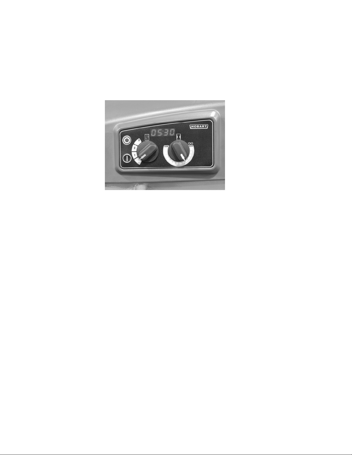
Fig. 9
Using the Count-Down Mode (Timed Mixing)
1. Turn the SPEED dial to select a mix speed.
a. If the count-up mode was used for the previous batch, the desired time needs to be
entered.
b. If the count-down mode was used for the previous batch, the previous time will be
displayed. If a different time is needed, turn the TIME selector to the desired time
in 10 second increments.
2. Press the START button to begin mixing; the timer starts counting down from the set
time.
a. To stop the mixer at any time, press the STOP button. To resume mixing, press the
START button. For example: The mixer is started at SPEED 1 for 30 seconds and is
stopped after 10 seconds. Pressing the START button will resume the mixing
operation.
b. If the mixer is stopped and a new time setting is entered, pressing the START
button saves the new time setting on the current speed selection.
For example: The mixer is started at SPEED 1 for 30 seconds and is stopped after 10
seconds. A new time is entered by turning the TIME selector. The new time will
replace the initial 30 seconds for SPEED 1 after the START button is pressed.
c. If the time is changed while mixing, the mixer will operate until the new time
expires. The adjustment to the time will not be stored.
d. If speed is changed while mixing, the time will change to the previous time for the
selected speed and count down.
NOTE: If the wire cage is opened at any time, the mixing operation will stop. To
resume the mixing operation, close the wire cage and press the START button.
13
Page 14
3. When the timer reaches 00:00, the mixer stops; a beeper sounds for 1 second. The
countdown timer then displays the last-stored time.
RECIPE TIMER OPERATION
Recipe Timer Notes
• If pause is selected as a mix speed, the mixer START button must be pressed to
advance to the next recipe step after the pause time has expired.
• If pause has been selected, the bowl guard can be opened and the time will
continue to count down.
• The recipe step can be interrupted and then resumed by pressing the STOP button
and then the START button.
NOTE: If PAUSE has been selected, the STOP button is disabled.
• The recipe can be terminated by stopping the mixer and pressing the STD button.
Using The Recipe Timer
1. Press Recipe mode button.
2. Turn the RECIPE selector to select a recipe.
3. Press START; mixer will operate at the programmed speed for the programmed
time.
a. Speed is displayed momentarily.
Fig. 10
b. Remaining time for the operating step will be displayed and the step light is
flashing.
NOTE: Recipe and Time selectors are disabled.
4. Mixer will continue to perform the programmed speeds and times until the recipe
steps are completed.
NOTE: If pause has been programmed for a step speed, the mixer START button must
be pressed to advance to the next recipe step after the pause time has expired.
5. When the timer reaches the end of the last programmed recipe step, the mixer
stops; the beeper sounds; the selected recipe is displayed.
14
Page 15
View Recipe
When the mixer is in RECIPE mode, you can view the step settings of any recipe.
1. Press the SELECT/SAVE button.
A. Display will alternate between speed and time.
B. The LED of the step being displayed will flash.
2. Use the arrow buttons to view the next step.
3. Use the Recipe selector to view other recipes.
4. Press PGM button to return to the RECIPE mode.
NOTE: If the mixer is performing a recipe, the recipe will continue to operate in normal
recipe mode sequence.
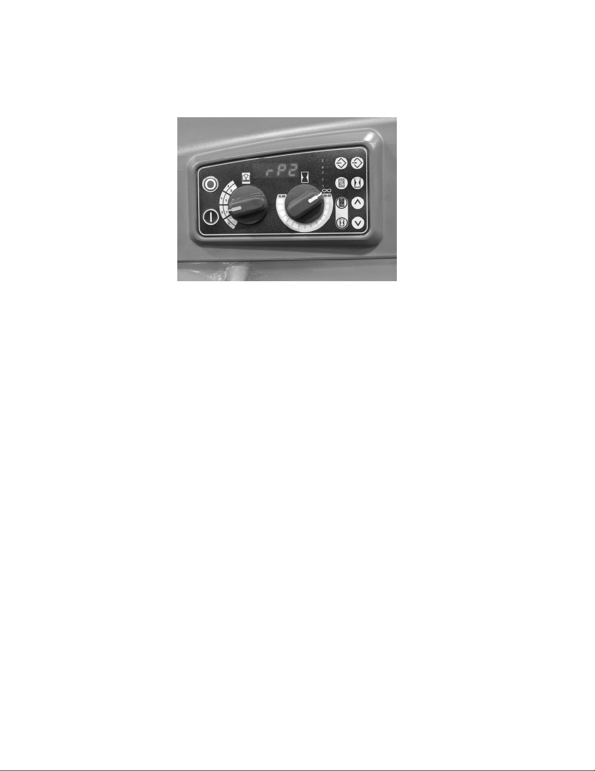
PROGRAMMING RECIPE TIMER
Fig. 11
HL200 is powered with display showing a mix time (Standard Mode) or recipe number (Recipe
Mode).
1. If a mix time is displayed, Press RECIPE mode button. Display corresponds with position of
recipe (speed) selector.
2. Press and hold TIME. Continue holding TIME, then press PGM and hold until rP1 is displayed
(with step 1 blinking), buzzer sounds and programmed step LEDs are lit.
3. Use arrows to select recipe number (1-4) for programming.
4. Press SELECT/SAVE to enter program mode for the recipe number selected.
Buzzer sounds and display alternates between speed and time to indicate programming mode.
15
Page 16

NOTES:
• If a value has been assigned for a step number, that LED will be lit.
• The LED for the selected step will blink.
• If the default value is still assigned to a step, the LED will not be lit.
• When programming, the Recipe and Time Selectors are disabled.
SPEED SETTINGS TIME SETTINGS
SPd 1 (DEFAULT) 00:00 – 15:00 minutes (10 second increments)
SPd 2 End (default)
SPd 3
Stir
PAUS (pause – no mixing)
5. Use arrows to select step number (1 – 5).
6. Press SPEED. All characters will blink and buzzer will sound.
A. Use arrows to select the mixing speed for selected step.
B. Press SELECT/SAVE to set the speed. SAVE displayed momentarily and buzzer sounds.
7. Display alternates between speed and time to indicate programming mode.
8. Press TIME. Third digit will blink and buzzer will sound.
A. Use arrows to select the mixing time (increments of 10 seconds) for selected step.
NOTE: If all 5 steps are programmed, the recipe will terminate at the end of step 5. If fewer than
5 steps are used, the default time setting of END will terminate the recipe.
B. Press SELECT/SAVE to set the time for the step. SAVE momentarily displayed and buzzer
sounds.
9. Display alternates between speed and time to indicate programming mode.
NOTE: LED of step programmed will be flashing.
10. Use arrows to select next step.
11. Repeat setting speed and time for additional steps and use SELECT/SAVE to save settings.
12. After all steps for recipe are programmed, press PGM to exit programming mode.
Buzzer sounds and display will show recipe number that was programmed with the number
blinking.
13. Press PGM to enter run mode. (Buzzer sounds)
14. Press STD to return to standard mode or set recipe selector to the desired recipe.
15. Select the recipe that you programmed and verify proper operation.
16
Page 17
6.8 UNLOADING.
1. Open the bowl guard wire cage assembly.
2. Lower bowl support.
3. Remove the agitator from the agitator shaft.
4. Slightly lift the bowl off the pin (right side), pull bowl to the front and remove from the
bowl support (left side).
6.9 GUARD WIRE CAGE.
The bowl guard wire cage can be rotated out of the way to add ingredients or to access the
bowl and agitator. Note how the plastic carriers allow the wire cage to ride around the
circumference of the planetary drip cup.
• Open the bowl guard wire cage: rotate it to your left (Fig. 12).
• Close the bowl guard wire cage: rotate it to your right until it stops, closed position
(Fig. 13).
NOTE: The bowl guard wire cage must be returned to the closed position for the mixer
to operate.
Fig.12 Fig. 13
17
Page 18
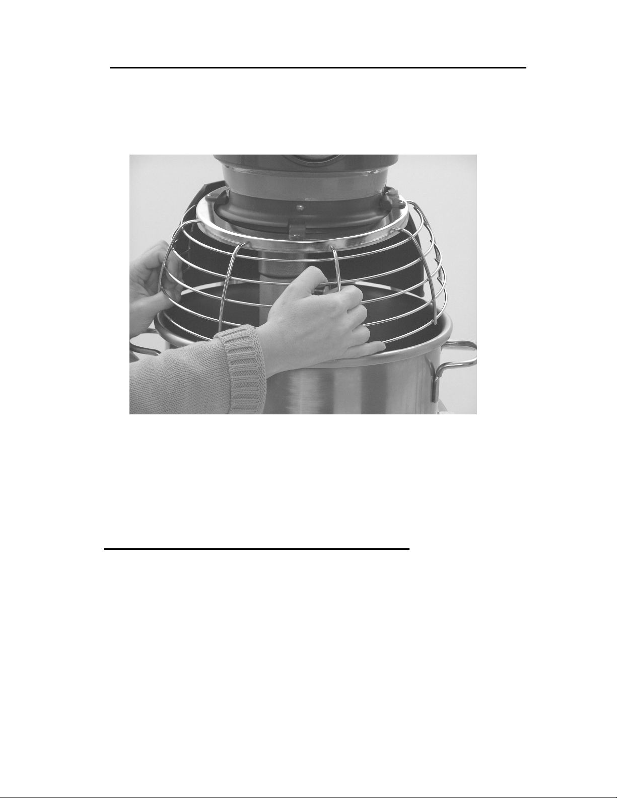
6.10 REMOVE AND CLEANING THE GUARD WIRE CAGE.
1. Rotate wire cage to your left until the three carriers align with the carrier escape slots in
the circular ridge of the planetary drip cup.
2. Lift the wire cage straight up so the carriers escape from the slots on the drip cup. The
bowl guard wire cage can now be removed by pulling toward you.
Fig. 14
3. Wash the bowl guard wire cage in a sink, rinse with clear water, and dry with a clean
cloth.
4. The splash guard can be wiped off and/or washed with a cloth or sponge using warm,
soapy water. Rinse with clear water and dry with a clean cloth.
6.11 RE-FITTING THE GUARD WIRE CAGE.
1. Position the ring of the bowl guard wire cage so the carriers are positioned above the
slots in the planetary drip cup.
2. Lower the bowl guard wire cage so the carriers pass through the slots.
3. Rotate the bowl guard wire cage to your right until it contacts the stop, closed position.
18
Page 19

6.12 MIXER CAPACITY CHART – HL200
Recommended Maximum Capacities—dough capacities based on 21°C water and
12% flour moisture.
PRODUCT
CAPACITY OF BOWL (LITRE LIQUID)
Egg Whites D 1 litre (1 qt.) .6 litre (1¼ pt.)
Mashed Potatoes B & C 6.8 kg (15 lbs.) 4.5 kg (10 lbs.)
Mayonnaise (Qts. of Oil) B or C or D 9.5 litre (10 qts.) 4.3 litre (4½ qts.)
Merinque (Qty. of Water) D
Waffle or Hot Cake Batter B 7.6 litre (8 qts.) 4.7 litre (5 qts.)
Whipped Cream D or C 3.8 litre (4 qts.) 2.4 litre (2 ½
Cake, Angel Food
(8-10 oz. cake)
Cake, Box or Slab B or C 9.1 kg (20 lbs.) 5.4 kg (12 lbs.)
Cake, Cup B or C 9.1 kg (20 lbs.) 5.4 kg (12 lbs.)
Cake, Layer B or C 9.1 kg (20 lbs.) 5.4 kg (12 lbs.)
Cake, Pound B 9.5 kg (21 lbs.) 5.4 kg (12 lbs.)
Cake, Short (Sponge) C or I 6.8 kg (15 lbs.) 3.6 kg (8 lbs.)
Cake, Sponge C or I 5.4 kg (12 lbs.) 2.9 kg (6 ½ lbs.)
Cookies, Sugar B 6.8 kg (15 lbs.) 4.5 kg (10 lbs.)
Dough, Bread or Roll §
(Lt.-Med.) 60% AR
Dough, Heavy Bread §
55% AR
Dough, Pie B & P 8.2 kg (18 lbs.) 5 kg (11 lbs.)
Dough, Thin Pizza 40% AR §
(max. mix time 5 min.)
Dough, Med. Pizza 50% AR § ED 4.5 kg (10 lbs.)□ 2.7 kg (6 lbs.)□
Dough, Thick Pizza 60% AR § ED 9.1 kg (20 lbs.)□ 5 kg (11 lbs.)□
Dough, Raised Donut
65% AR
Dough, Whole Wheat
70% AR
Eggs & Sugar for Sponge Cake B & C or I 3.6 kg (8 lbs.) 2.3 kg (5 lbs.)
Icing, Fondant B 5.4 kg (12 lbs.) 3.2 kg (7 lbs.)
Icing, Marshmallow C or I .9 kg (2 lbs.) .6 kg (1 ¼ lbs.)
Shortening & Sugar,
Creamed
Pasta, Basic Egg Noodle
(max. mix time 5 min.)
AGITATORS
SUITABLE FOR
OPERATION
C or I 6.8 kg (15 lbs) 3.2 kg (7 lbs)
ED 11.3 kg (25 lbs.)□ 5.9 kg (13 lbs.)□
ED 6.8 kg (15 lbs.)□ 3.6 kg (8 lbs.)□
ED 4.1 kg (9 lbs.)□ 2.3 kg (5 lbs.)□
ED 4.1 kg (9 lbs.)* 1.8 kg (4 lbs.)*
ED 9.1 kg (20 lbs.)□ 5 kg (11 lbs.)□
B 7.3 kg (16 lbs.) 4.3 kg (9 ½ lbs.)
ED 2.3 kg (5 lbs.) ---
20 12
.7 litre (1
HL200
1/2
pts.) .4 litre (¾ pt.)
qts.)
19
Page 20

ABBREVIATIONS - AGITATORS
SUITABLE FOR OPERATION
B - Flat Beater
C - Wing Whip
D - Wire Whip
ED - Dough Hook
I - Wire Whip
P - Pastry Knife
□1st Speed
* 2nd Speed
NOTE: %AR (% Absorption Ratio) = Water weight
divided by flour weight. Capacity depends on
moisture content of dough. Above capacities based
on 12% flour moisture at 21°C water temperature.
§ If high gluten flour is used, reduce above dough
batch size by 10%.
2nd speed should never be used on 50% AR or lower
Products.
Use of ice requires a 10% reduction in batch size.
NOTE: Attachment hub should not be used while mixing.
20
Page 21

6.13 AGITATORS AND ATTACHMENTS.
Hobart Quick Release ™ agitators are available for the Legacy mixers and for
the type of product that is being mixed.
The B Flat Beater is a multi-purpose agitator used for mashing
potatoes or other vegetables, and mixing cakes, batters or icings. It is
also used in industrial applications for any product requiring a
creaming or rubbing action and uniform dispersion of ingredients. Use
first speed for starting most operations; medium speed for finishing.
The D Wire Whip is designed for maximum blending of air into light
products. Uses include: whipping cream, beating egg whites, mixing
very light icings, meringues and all similar applications. The D Wire
Whip is most commonly used in third and fourth speed.
The ED Dough Hook is used for mixing most bread, roll and
pizza dough, which require folding, and stretching action for best
development. These agitators are suitable for use on all yeast raised
doughs and should be operated in first, second or third speed.
The C Wing Whip is used for whipping material that is too heavy for
the D Wire Whip. The heavy frame permits its use for light creaming
and beating. It is often used for whipping or blending potatoes, butter,
and mayonnaise or light icings. It is generally used in first and second
speed for whipping heavy products like potatoes or in third or fourth
speed for light products such as mayonnaise or icings.
The P Pastry Knife combines shortening with flour, and is ideal for
light pastry shells (patty shells), flaky pie dough and similar mixes. The
cutting action of the knife practically eliminates rubbing and allows
delicate ingredients to be combined without over development. The P
Pastry Knife is suitable for stirring operations in low speeds and for
fast cutting operations in medium speeds. You should not use the
P Pastry Knife at high speed if you want the pastry to have a flaky
texture.
21
Page 22

6.13.1 USING THE ATTACHMENT FACILITY.
MEAT CHOPPER ATTACHMENT
The Meat Chopper Attachment allows you to prepare many additional foods with your Hobart mixer.
A plate having 4-mm holes comes with the Meat Chopper Attachment when shipped from the
factory. The maximum allowable hole diameter in the mincing plate is 8 mm and the plate thickness
must be greater than 5 mm. If the plate hole diameter is greater than 8 mm an interlocked protective
hood is required. The results are the same as produced by Hobart commercial meat choppers.
Operate Meat Chopper Attachments in third speed on the HL200 mixer. The feed pan should be
kept in place in the cylinder for ease of feeding. Cut meat into strips and feed it into the chopper
using the feed stomper only as needed. Substances that could become packed tight in the chopper
like breadcrumbs are not recommended. If material in the cylinder stalls the mixer, push the
STOP button at once. DO NOT attempt to restart at a slower speed. Remove the adjusting ring,
knife, plate and worm and clear the obstruction. Always keep the drain hole on both the Attachment
Hub and Meat Chopper clean, clear and free of obstruction.
6.13.2 SPLASH COVER
The splash cover provides a means for minimising dust emissions and reducing splashing for certain
mixes at higher speeds. Splash covers fit under the Bowl Guard. Splash Covers, while convenient
accessories, should not be used to increase the mixing capacity beyond the recommended
maximum. The best functioning of Hobart mixers requires room at the top of the bowl for aeration
and manipulation. Follow the Hobart Mixer Capacity Chart of the best quality of mix. Splash Covers
on larger mixers have a smaller diameter opening at the top due to their inverted cone shape.
Overloading the mixer while a splash cover is in use reduces aeration because of restriction in the
area where air enters the batch.
6.13.3 BOWL SCRAPER ATTACHMENT.
The mixer Bowl Scraper Attachment is available for the HL200 Mixer full and half size bowls. This
attachment scrapes the sides of the bowl as the agitator rotates to re-introduce material into the
mixture. The scraper must only be used with the whip or flat beater agitators.
6.14 CLEANING.
CLEANING NEW MIXER BOWLS AND ACCESSORIES
Before using the first time, thoroughly wash new mixer bowls and agitators (beaters,
whips, dough hooks and pastry knives). Wash in hot water and a mild detergent solution,
rinsing with either a mild soda or vinegar solution, and thoroughly rinse with clear water.
Also follow this cleaning procedure for bowls and agitators before whipping egg whites or whole
eggs.
6.14.1 CLEANING AFTER USE.
After use, clean the mixing bowl, agitators and attachment with hot water, using a
suitable non-abrasive detergent and soft bristle brush. (Flushing the bowl with hot
water immediately after use will ease the cleaning).
Note: Do not clean the aluminium agitators in a dishwasher.
22
Page 23
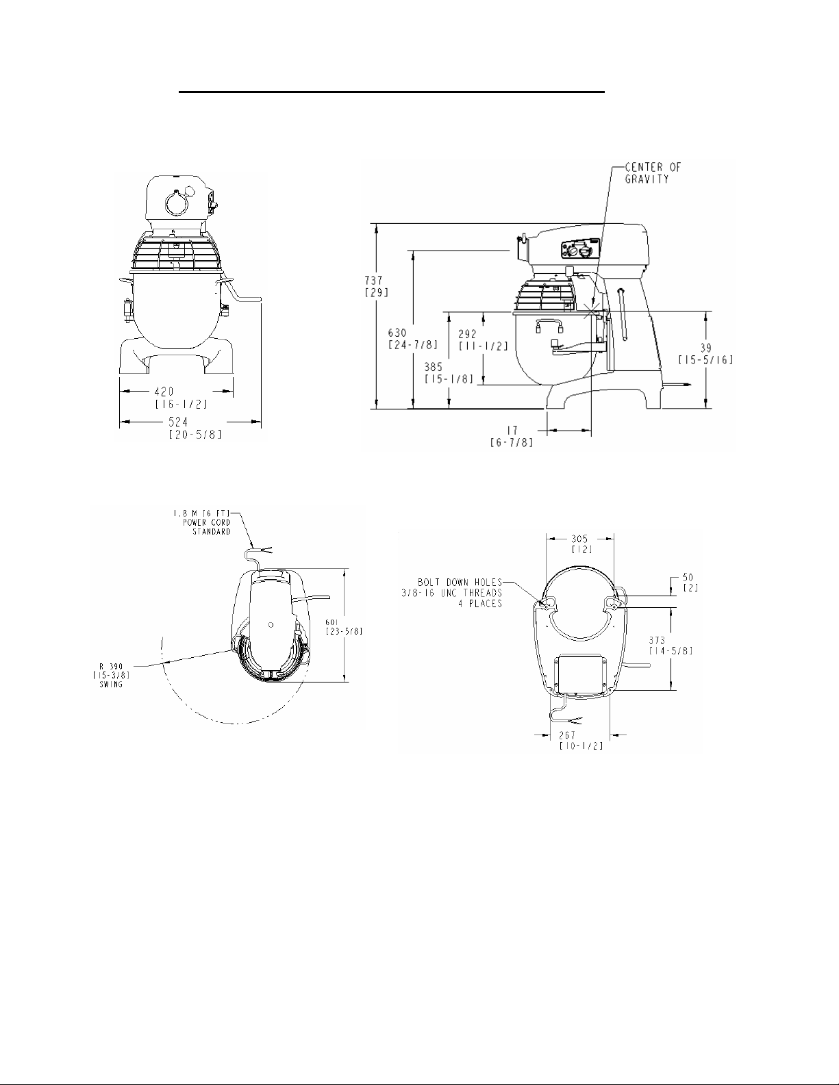
6.15 INSTALLATION AND COMMISSIONING.
TOP VIEW BOTTOM VIEW
Fig. 15
Overall Dimensions.
A 12-litre bowl and agitators are also available.
A variety of attachments, agitator and accessories are available. These are described in
Section 6.13 (page 21) of this manual.
23
Page 24
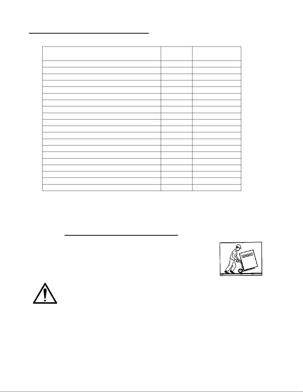
Table 1. Technical Information.
Description Units HL200
Mixer power kW (hp) 0.37 (1/2)
Maximum speed of rotating part (50Hz) rpm 2775
Nominal electrical supply 1 ph Volts 230
Full load current at above voltage 1 ph Amps 5.0
Locked rotor current at above voltage 1 ph Amps 10
Recommended fuse size 230v/1 ph/50Hz Amps 10
Minimum ambient temperature
Maximum ambient temperature
Transmission case lubricating grease capacity Litres 0.8
Attachment hub drive size -- # 12
Mixer weight (Bowl Included) Kg (lbs) 85.7 (189)
Bowl weight (12 litre) Kg (lbs) 3.4 (7.5)
Bowl weight (20 litre) Kg (lbs) 4.2 (9.3)
Agitator weight (20 litre beater) Kg (lbs) 0.95 (2.1)
Noise level dB (A) less than70##
Shipping weight (Bowl included) kg (Lbs) 92.5 (204)
Shipping dimensions (carton) LxWxH cm 62.8 x 57.8 x 87.3
Storage conditions. Temperature and humidity.oC, % RH +5 to +38, 85
Class of appliance Class 1#
Enclosure IP rating IP45
#
Refer to Section 6.18
##
In accordance with EN-ISO 12001:1996.
o
C 0
o
C 40
6.16 UNPACKING AND HANDLING.
Wherever possible the food mixer should be transported to the installation
position in the packaging provided to avoid damage. Do not use a sharp
knife to cut into the box as damage to the machine may occur. Check for
possible shipping damage. If the unit is found to be damaged, save the
packaging material and contact your nearest Hobart sales office.
Caution: The HL200 mixer is a heavy object and must be correctly handled and lifted
to avoid personal injury. Refer to Table 1, page 24 for weights and dimensions. For
UK installations refer to the ‘Manual Handling Operations Regulations 1992 and HSE
guidance notes for manual handling.
With the machine in the vicinity of its final position, remove from outer carton. Remove mounting
bolts under skid attached to mixer base. Remove mixer from skid forking from the side of unit.
When moving unit, always fork from side of unit.
Care must be taken during this operation to ensure:
24
Page 25
a) All required safety measures are taken to ensure correct lifting and handling to avoid risk of
injury through dropping, falling and tilting.
b) No damage occurs to the machine, which could impair the normal operation.
6.17 LOCATION.
The mixer is not suitable for outdoor installation and must not be installed where a water
jet could be used for cleaning. The mixer must only be operated by trained staff and
must be installed in an area where the use and maintenance is restricted to trained
personnel.
The mixer must be installed on a horizontal flat surface level to a minimum of 1mm in 1 metre side to
side and front to back. Select a suitable flat level surface that can support the weight of the mixer
and bowl contents when full (refer to Table 1 for weights and dimensions). In areas where stability
may be an issue, the machine should be secured in position.
Ensure there is sufficient space around the mixer for the user to operate the controls and to install
and remove bowls. The area above and to the rear side of the mixer should allow the top and rear
covers to be removed for routine maintenance and servicing. Servicing may be more difficult
because of reduced clearances and you should always check that equipment specifications permit
the close proximity of other equipment. Refer to Fig. 15, page 23 for the overall dimensions of the
mixer and the clearance required to accommodate the hinged bowl.
6.18 ELECTRICAL INSTALLATION.
The electrical installation of the mixer must conform to the local electricity board
regulations. When installed in the United Kingdom the installation must be in
accordance with the current edition of the IEE Regulations for electrical equipment in
buildings and must conform to the requirements of the Electricity at work act.
A competent person must carry out the electrical installation.
The technical data shown in Table 1, page 24 details the electrical requirements for the mixer.
Ensure that the electrical power supply agrees with the machine specification prior to connection.
The mixer is equipped with a three-wire power supply cord ready for installation of an appropriate
grounding-type attachment plug. The plug and its mating receptacle must be properly grounded.
Contact an electrician. Provide proper fuse or circuit breaker protection.
25
Page 26
r
6.19 OPERATOR TRAINING.
Take time to explain the correct operation and cleaning of the Legacy mixer to the users referring to
this manual. Leave this manual with the operator and explain that it is important to use it for further
reference.
7.0 MIXER MAINTENANCE.
WARNING: UNPLUG MACHINE POWER CORD BEFORE BEGINNING ANY MAINTENANCE
PROCEDURES.
WARNING! THE ELECTRONIC DRIVE CONTROL IS FITTED WITH HIGH VOLTAGE
CAPACITORS. ISOLATE THE MIXER FROM THE MAINS AND ALLOW THE CAPACITORS
TO DISCHARGE FOR 5 MINUTES BEFORE REMOVING ANY COVERS.
A HOBART TRAINED AND COMPETENT PERSON SHOULD CARRY OUT
SERVICING.
Do not remove any covers or loosen any fittings while the mixer is operating.
Ensure the electrical supply has been isolated before attempting to service or
move the mixer.
7.1 LUBRICATION.
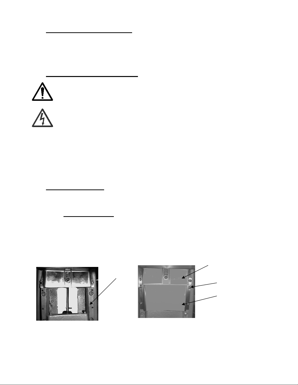
7.1.1 SLIDEWAYS.
The slideways (Fig. 16) should be lubricated approximately twice a year. To reach these
areas, fully lower the bowl support and remove the apron, which is secured by slotted
screws. Wipe a thin coat of Lubriplate 630AA on the bowl pad area of the bowl supports and
on each slideway. Replace the apron and secure with screws. Refer to the recommended
spare parts section for Lubriplate oil part number.
Slideway
Sensor
Holde
Screws
Apron
Fig. 16
NOTE: Do not remove sensor holder screws to remove apron.
Fig. 17
26
Page 27
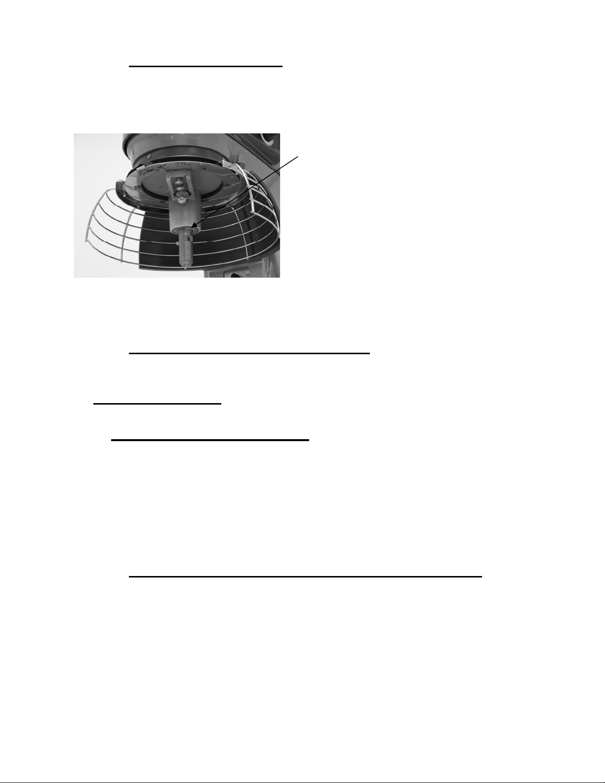
7.1.2 PLANETARY SEAL.
Occasionally, the planetary seal (Fig. 18) may become dry and begin to squeak. To correct
this, work a little lubrication (mineral oil) under the lip of the seal.
Planetary
Seal
Fig. 18
7.1.3 BOWL LOCKING MECHANISM.
Bowl Locking Mechanism should be lubricated after cleaning. Clean only if sticking or hanging up.
7.2 ADJUSTMENTS.
7.2.1 AGITATOR CLEARANCE.
The agitator clearance should be checked periodically. The agitator must not touch the bowl
and the maximum clearance between the bottom of the bowl and the B flat beater is (1/8")
3 mm; the maximum clearance between the bottom of the bowl and the ED dough arm is
(5/16”) 8 mm.
Install a bowl and agitator (e.g., beater). If the bowl and beater come into contact before the
bowl support reaches its stop, adjust the stop screws. Refer to Adjust the Bowl/Agitator
clearance.
7.2.2 TO MEASURE THE AGITATOR CLEARANCE.
Pour enough flour in the bowl to cover the bottom of the bowl where the beater travels.
With the bowl fully raised (beater should not touch the bottom of the bowl), briefly run the
mixer at the lowest speed.
Turn off the mixer, disconnect the electrical power supply, and measure the depth of flour
where the beater has traced a path. This measurement should be taken at several points
around the bowl to assure accuracy.
27
Page 28
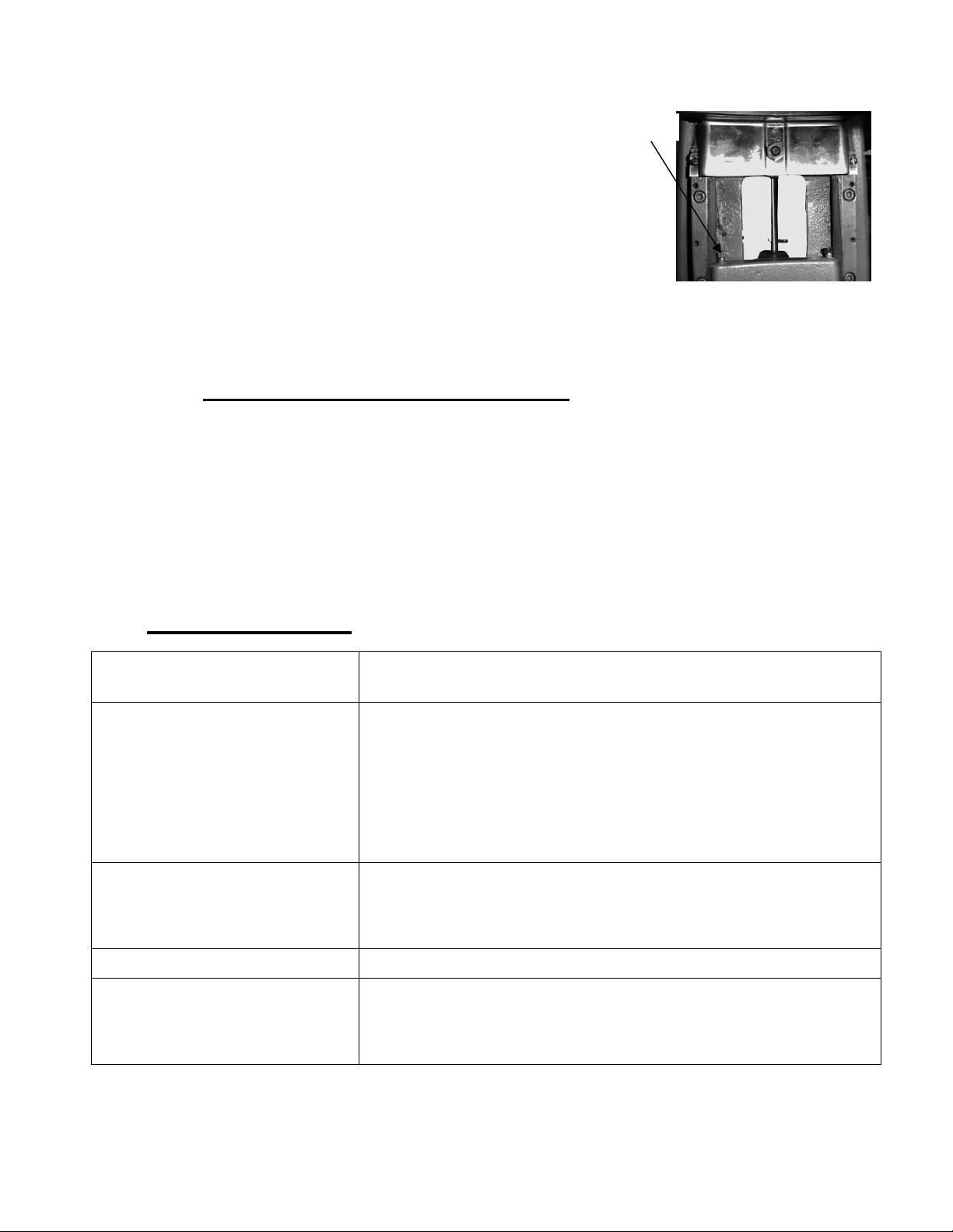
Adjust the Bowl/Agitator Clearance
• Remove the apron (which is secured by screws).
• Adjust the clearance by loosening the stop screws
counterclockwise to increase the clearance or clockwise
to decrease the clearance.
• After the adjustments are made, replace the
apron and secure it with the screws.
• Carefully operate the bowl lift several times to
check the adjustment.
Stop Screws
Fig. 19
7.3 INTERLOCK SAFETY SYSTEM.
Regular inspection of the mixer safety system is necessary to check the operation of the bowl, guard
and bowl support interlock switches. This must be performed no less than once a year.
A spare parts manual is available on request from Hobart Spare Parts Distribution Centre. For
continued safe and reliable operation of this mixer, it is recommended that servicing is only carried
out by Hobart trained service personnel.
8.0 FAULT FINDING.
Symptoms Possible Causes
Mixer will not start. Flashing Time Display – See Below
Agitator touches bowl. Bowl is not in closed (mix) position.
Planetary seal squeaks. Seal requires occasional lubrication - see Maintenance.
Timer displays flashing alarm
code (Ex. “OL1” – Motor
overload)
Branch circuit protector is in open position - check fuse or
disconnect switch.
Mixer is overloaded.
Wire cage is not in the closed position.
Bowl is not in closed (mix) position or if Bowl in not in up
position.
Improper agitator clearance - see Maintenance for adjustment
procedure.
Agitator is not installed properly.
If the error code is flashing – unplug machine until display is
blank then plug back in. If symptoms still exist, contact your
local Hobart Service office.
28
Page 29

9.0 RECOMMENDED SPARES.
Part Number Description
00-874831 Switch – Speed Selector Assy
00-874809 Knob
00-087714-067-1 Relay (2 Pole, 30 Amp)
00-108197-00001 Screw – Thumb 1.125
00-291221 Worm – Gear 60 Cycle
00-874816 Carrier – Wire Cage
00-874816-00002 Carrier – Wire Cage (Slotted)
00-874816 Carrier – Wire Cage
00-874875 Magnet – Disc
00-874822 Wire Cage Assy
00-874815 Guard – Splash
00-874832 Cup – Drip & Flange
00-874864 Bowl Assy (12 Litre SST Packaged)
00-874834 Bowl Assy (20 Litre SST Packaged)
00-118801 Scraper – Bowl (Handheld)
00-874828 “B” Beater (12 Litre Packaged)
00-873360 “D” Wire Whip (12 Litre Packaged)
00-873343 “ED” Dough Arm (12 Litre Packaged)
00-875893 “C” Whip (12 Litre Packaged)
00-873370 Pasty Knife (12 Litre Packaged)
00-873313 “EDA” Dough Arm (20 Litre Packaged)
00-873331 “C” Whip (20 Litre Packaged)
00-873335 “E” Dough Arm (20 Litre Packaged)
00-874792 “D” Wire Whip (20 Litre Packaged)
00-874791 “ED” Dough Arm (20 Litre Packaged)
00-874790 “B” Beater (20 Litre Packaged)
00-873294 Pasty Knife (20 Litre Packaged)
00-873373 Scraper (12 Litre Packaged)
00-874836 Scraper (20 Litre Packaged)
00-438078 Splash Cover (12 Litre Packaged)
29
Page 30

00-438079 Splash Cover (20 Litre Packaged)
00-874885 Ingredient Chute (Packaged)
ML-134299 Mixer Table with Casters
00-874929 Reed Switch w/Fuse
00-916194 Filter and Bracket Assy
00-874761-00005 Motor Drive Assy
00-916197 Motor and Worm Assy
30
Page 31

10.0 NOTES.
31
Page 32

11.0 SERVICE CONTACT NUMBERS.
Hobart trained service technicians strategically located throughout the UK are prepared to give you
fast, efficient and reliable service. Protect your investment by having a Hobart inspection contract,
which assures the continued, efficient operation of your Hobart machines, spares and accessories.
For disposal of mixer, contact Hobart Service Centre for return details.
For further details please contact: -
Department Telephone Facsimile
SALES: 07002 101 101 02088 864 396
SERVICE 07002 202 202 01733 371 709
SPARES 07002 303 303 01733 371 332
Continued product improvement is a Hobart UK policy, specifications may change without notice.
Hobart UK
Hobart House, 51 The Bourne,
Southgate, London N14 6RT
Tel: 07002 101101 Fax 0208 886 4396
F-34941 (Oct 2005)
32
Page 33

HL200
Page 1 - English
Page 33 - Français
Page 67 - German
ML-134311
INSTALLATION AND OPERATION MANUAL
MANUEL D’INSTALLATION ET D’UTILISATION
INSTALLATIONS UND BEDIENUNGSANLEITUNG
F-34941 (Octobre 2005)
33
Page 34

Français / Table des matières
Section Page
Informations sur la sécurité 1.0 36
Directives sur la sécurité 1.1 36
Symboles d’avertissement 1.2 37
Responsabilité 1.3 37
Avant-propos 2.0 37
Informations générales 3.0 37
Prendre soin de votre environnement 4.0 38
Les Matieres D’Emballage 4.1 38
Pour éliminer votre ancien appareil 4.2 38
Instructions de sécurité 5.0 38
Danger provenant de la poussière 5.1 38
Ne jamais 5.2 39
Toujours 5.3 39
Instructions de sécurité pour accessoires
Utilisation du batteur - mélangeur 6.0 40
Première utilisation 6.1 40
Identification des composants du batteur - mélangeur Figure 1 41
Commandes minuterie standard 6.2 42
Commandes minuterie recette 6.2 43
Positionnement du bol 6.3 44
Agitateur 6.4 44
Préparation au mixage 6.5 45
Notes pour l’utilisation 6.6 45
Fonctionnement de la minuterie standard 6.7 45
Fonctionnement de la minuterie recette 6.7 47
Visualisation de la recette 6.7 48
Programmation de la minuterie recette 6.7 48
Déchargement 6.8 50
Panier métallique de protection 6.9 50
5.4 39
Retirer et nettoyer le panier métallique de protection 6.10 51
Remonter le panier métallique de protection 6.11 52
Tableau de capacité de mélange 6.12 52
Agitateurs et accessoires 6.13 54
34
Page 35

Utilisation du dispositif accessoire 6.13.1 55
Couvercle anti-projections 6.13.2 55
Dispositif racleur du bol 6.13.3 55
Nettoyage 6.14 56
Nettoyage après utilisation 6.14.1 56
Installation et mise en service 6.15 57
Dimensions Fig. 15 57
Informations techniques Tableau 1 58
Déballage et manutention 6.16 58
Localisation 6.17 59
Installation électrique 6.18 59
Formation de l’opérateur 6.19 60
Maintenance du batteur - mélangeur 7.0 60
Lubrification 7.1 60
Glissières 7.1.1 60
Joint planétaire 7.1.2 61
Mécanisme de blocage du bol 7.1.3 61
Réglages 7.2 61
Dégagement de l'agitateur 7.2.1 61
Pour mesurer le dégagement de l'agitateur 7.2.2 61
Système de sécurité par verrouillage 7.3 62
Dépannage 8.0 62
Pièces de rechange recommandées 9.0 63
Notes 10.0 65
Numéros de contact pour le service après-vente 11.0 66
© Hobart 2005
35
Page 36

1.0 INFORMATION SUR LA SÉCURITÉ.
Les procédures et précautions contenues dans le présent manuel ne s'appliquent qu'à la machine
lorsqu'elle est utilisée de la façon prescrite.
Si la machine est utilisée autrement que de la façon prescrite, l'opérateur sera responsable de sa
propre sécurité et de la sécurité des autres personnes qui peuvent être concernées.
Les informations contenues dans le présent manuel ont été préparées pour aider l'opérateur à
comprendre, entretenir et utiliser le batteur - mélangeur. Afin d'éviter les accidents, il convient de
lire, assimiler et suivre toutes les précautions et avertissements contenus dans le présent manuel
avant installation ou première utilisation. Ce manuel doit être étudié pour obtenir une compréhension
claire du batteur - mélangeur et de ses capacités.
1.1 DIRECTIVES SUR LA SÉCURITÉ.
S'assurer que des précautions suffisantes sont observées au cours de la manipulation manuelle du
batteur - mélangeur, en particulier lors de la mise en place pendant l'installation. On se réfèrera aux
réglementations de manipulations manuelles. Les poids du batteur - mélangeur sont donnés au
Tableau 1.
• Ne pas nettoyer cet appareil au jet d'eau ni au nettoyeur sous pression. Il est vital d'adhérer aux
instructions de nettoyage décrites en détail dans la section 9 du présent manuel.
• Ne pas retirer de couvercle ni desserrer des accessoires pendant que la machine est en
marche.
• S'assurer que ce manuel est conservé dans un lieu facilement accessible à proximité du batteur
- mélangeur, pour référence ultérieure.
• Tous les opérateurs doivent être formés au fonctionnement du batteur - mélangeur et de ses
accessoires en toute sécurité.
• S'assurer que l'alimentation électrique a été coupée avant d'essayer d'entretenir ou de déplacer
le batteur - mélangeur.
• Les machines tournantes et l'électricité sont potentiellement dangereuses et peuvent blesser si
l'on ne prend pas suffisamment de précautions avant d'utiliser ou d'entretenir la machine.
• Faire réviser régulièrement le batteur - mélangeur et les accessoires, au moins deux fois par an,
en fonction de la fréquence d'utilisation.
• Lorsqu'on mélange des produits qui produisent de la poussière, on prendra toutes les
précautions utiles. Mélanger les ingrédients en utilisant le dispositif STIR jusqu'à ce que la
poussière soit éliminée.
L'exposition à la poussière (y compris la farine) peut être dangereuse pour la santé, et sera la cause
de rhinites, d'écoulement des yeux et peut-être d'asthme.
36
Page 37

1.2 SYMBOLES D’AVERTISSEMENT.
Pour identifier les messages de sécurité dans le présent manuel, les symboles suivants ont été
utilisés.
Le symbole "Avertissement" se trouve essentiellement lorsque l'information
correspondante est importante pour la bonne utilisation de l'appareil en toute sécurité.
Le symbole de danger électrique est utilisé lorsqu'il y a des risques de nature électrique.
Avant de réviser l'appareil, toujours débrancher le câble d'alimentation électrique du
secteur.
1.3 RESPONSABILITÉ.
Les installations et réparations qui ne sont pas effectuées par des Techniciens Autorisés, ou
l'utilisation de pièces de rechange autres que les pièces d'origine, et toutes modifications
techniques de la machine, peuvent mettre en danger la garantie fixée dans les conditions de
vente standard.
2.0 AVANT-PROPOS.
Hobart se réserve le droit de modifier la conception de ses produits sans préavis. Bien que tous les
efforts nécessaires aient été faits pour que cette publication reflète la toute dernière conception de
l’appareil, la société ne peut pas garantir une totale conformité.
Prenez soin de votre batteur - mélangeur HL200 – gardez-le propre et en bon état mécanique et
électrique.
3.0 INFORMATIONS GÉNÉRALES.
Les présentes informations et instructions contenues dans ce manuel peuvent ne pas couvrir tous
les détails ni les variations de l'équipement, ni tenir compte de toutes possibilités pouvant de
produire avec l'installation, l'utilisation ou la maintenance. Si des informations supplémentaires sont
requises, veuillez contacter votre bureau Hobart local.
Le batteur - mélangeur HL200 est conçu pour mélanger des produits alimentaires comme détaillé
dans le tableau de spécification (Section 6.12, page 52).
Le batteur - mélangeur 20 litres Legacy est un batteur - mélangeur de table qui est équipé en
version standard du système de minuterie SmartTimer™, d’un dispositif de levage de bol manuel et
de la prise d’accessoires de type 12. En utilisant des agitateurs spéciaux, il est possible d’utiliser un
bol de 12 litres avec le mixeur HL200.
La machine est prévue pour fonctionner sur les alimentations électriques indiquées au Tableau 1,
page 58.
Le batteur - mélangeur est équipé d'un dispositif de sécurité à "ouverture sans volt" pour éviter un
redémarrage automatique après panne de courant ou déconnexion du secteur. Le support du bol et
la protection sont à verrouillage par verrouillage de telle façon que si l'un ou l'autre n'est pas dans sa
position de fonctionnement correcte, le batteur - mélangeur ne fonctionne pas. Le batteur mélangeur standard est fourni avec protection, bol et agitateurs.
37
Page 38

4.0 PRENDRE SOIN DE VOTRE ENVIRONNEMENT.
4.1 LES MATIÈRES D’EMBALLAGE.
La palette et son film d'emballage protecteur en polyéthylène ont été
sélectionnés à partir de matières qui respectent l'environnement lors de leur
élimination ou qui peuvent être normalement recyclées. Au lieu de les jeter, veuillez vous assurer
qu'ils sont recyclés
.
4.2 POUR ÉLIMINER VOTRE ANCIEN APPAREIL.
Les anciens appareils contiennent des matières qui peuvent être recyclées. Veuillez contacter votre
centre local de collecte des déchets; récupérateurs de métaux ou le bureau Hobart local sur les
systèmes de recyclage possibles.
5.0 INSTRUCTIONS DE SÉCURITÉ.
SEULE UNE PERSONNE DUMENT FORMÉE ET COMPÉTENTE DOIT UTILISER
L'ACCESSOIRE ET / OU LE BATTEUR - MELANGEUR.
Les instructions suivantes doivent être observées lorsqu'on utilise le batteur - mélangeur.
NB : Le batteur - mélangeur ne doit être utilisé que dans le but pour lequel il a été conçu et
conformément aux instructions d'exploitation fournies.
N'utiliser que des accessoires conformes aux réglementations CE (marqués CE).
5.1 DANGER PROVENANT DE LA POUSSIÈRE.
Pour réduire au minimum tout danger de poussière, suivre les instructions détaillées ci-dessous.
Lorsqu'on mélange des ingrédients, on prendra soin d'éviter de respirer les particules de poussière,
par exemple la farine. On se réfèrera aux fiches de données du fournisseur de produit pour
s'assurer que des précautions / protections adéquates sont prises.
Les articles tels que la farine doivent être ajoutés de façon à éviter la dispersion des particules de
poussières dans l'atmosphère locale.
Fendre soigneusement le sac tout en le maintenant dans la partie inférieure du bol. En mélangeant
des ingrédients secs, utiliser la vitesse la plus basse pour réduire au minimum la propagation de
poussière. Utiliser un couvercle anti-projections pour réduire la production de poussière (voir la
Section 9, Pièces de rechange recommandées, page 63 pour le numéro de pièce du couvercle).
Mélanger les ingrédients dans le bol en utilisant la vitesse la plus basse jusqu'à ce que le risque de
production de poussière soit éliminé.
Monter un équipement d'extraction de poussière approprié.
38
Page 39

5.2 NE JAMAIS .
• Faire fonctionner le batteur - mélangeur ou les accessoires si un défaut apparaît ou si le
batteur - mélangeur ne fonctionne pas en sécurité.
• Porter des vêtements amples.
• Essayer de mettre la main dans le bol pendant le mélange.
• Accéder aux pièces tournantes.
• Monter l'agitateur sur le batteur - mélangeur sans bol en place.
• Laisser l'agitateur sur l'appareil sans monter le bol.
• Actionner le batteur - mélangeur avec les accessoires et l'agitateur montés.
• Utiliser une force excessive lors de l'utilisation, ce qui pourrait avoir un effet négatif sur la
stabilité du batteur - mélangeur.
• Faire fonctionner le batteur - mélangeur si des pièces sont démontées.
• Annuler les contacts de sécurité montés sur le batteur - mélangeur.
• Ouvrir la protection pour arrêter la machine.
• Utiliser le dispositif de levage du bol pour arrêter la machine.
• Utiliser le batteur - mélangeur dans un état contraire à la sécurité.
• Nettoyer le batteur - mélangeur avec de la poudre décapante ou un tampon décapant.
• Nettoyer les agitateurs en aluminium dans un lave-vaisselle.
• Respirer les particules de poussière des ingrédients de mélange.
5.3 TOUJOURS.
• Utiliser le batteur - mélangeur dans une zone bien éclairée.
• S'assurer que le bol, l'agitateur, l'accessoire et la protection sont correctement fixés au
batteur - mélangeur.
• Débrancher l'alimentation électrique secteur avant de nettoyer le batteur - mélangeur.
• Nettoyer le batteur - mélangeur quotidiennement.
• Retirer l'agitateur avant d'utiliser des accessoires.
• Arrêter le batteur - mélangeur avant d'ajouter d'autres ingrédients.
• Utiliser le bouton d'arrêt pour arrêter la machine.
• Nettoyer le bol, les agitateurs et les accessoires après utilisation.
• Nettoyer le batteur - mélangeur en utilisant du savon doux et de l'eau.
• Réviser le batteur - mélangeur et les accessoires au moins deux fois par an en fonction de la
fréquence d'utilisation.
• Utiliser le batteur - mélangeur comme prévu et conformément aux instructions d'utilisation.
• Utiliser l'équipement de taille réduite correct (bol et agitateur).
• Utiliser des accessoires qui sont agréés CE et marqués CE.
5.4 INSTRUCTIONS DE SÉCURITÉ POUR LES ACCESSOIRES.
Les instructions suivantes doivent être observées lorsqu'on utilise le batteur - mélangeur avec ses
accessoires. Se référer également aux instructions de sécurité de la Section 5.0, page 38 et les
instructions fournies avec l'accessoire. Seuls les accessoires marqués et agréés CE doivent être
utilisés.
SEULE UNE PERSONNE BIEN QUALIFIÉE ET COMPÉTENTE DOIT UTILISER
L'ACCESSOIRE ET / OU LE
• Ne pas monter un accessoire quand le batteur - mélangeur fonctionne.
• Ne pas porter de vêtements amples.
39
Page 40

• Ne pas utiliser le batteur - mélangeur ou l'accessoire si un défaut se produit ou si la machine
n'est pas sûre.
• Ne pas accéder aux pièces tournantes.
• Ne pas utiliser une force excessive en faisant fonctionner l'accessoire, car cela pourrait
affecter la stabilité du batteur - mélangeur.
• Ne pas utiliser le batteur - mélangeur si des pièces sont démontées.
• Toujours utiliser l'accessoire et / ou le batteur - mélangeur dans une zone bien éclairée.
• Toujours s'assurer que l'accessoire fonctionne à la vitesse correcte.
• Toujours nettoyer les accessoires après utilisation et se référer aux instructions de nettoyage
du fabricant d'accessoires.
• Toujours réviser votre batteur - mélangeur et ses accessoires régulièrement ; au moins deux
fois par an, en fonction de la fréquence d'utilisation.
6.0 UTILISATION DU BATTEUR - MÉLANGEUR.
6.1 PREMIÈRE UTILISATION.
Avant l’installation, veuillez tester votre installation électrique afin de vous assurer qu’elle
correspond aux caractéristiques techniques indiquées sur la plaque de la machine.
Placer le batteur - mélangeur sur une surface dure adéquate. Laisser un espace suffisant autour
de l’appareil pour pouvoir accéder aux commandes et installer ou retirer les bols.
Des trous se trouvent à la base de l’appareil pour permettre une sécurité permanente du batteur mélangeur, bien qu’ils ne soient pas nécessaire lors d’une utilisation normale.
Ce batteur - mélangeur alimentaire n'est prévu que pour utilisation
professionnelle par des personnes adéquatement qualifiées. S'assurer que les
opérateurs ont lu et assimilé ce manuel et ont reçu une formation adéquate.
QUAND L'AGITATEUR EST DANS LE BOL, NE PAS APPROCHER LES MAINS,
LES VÊTEMENTS OU DES USTENSILES PENDANT QU'IL FONCTIONNE. NE PAS
L'UTILISER SANS PROTECTION A SECURITE PAR VERROUILLAGE.
Le batteur - mélangeur Legacy est équipé de la commande Smart ™ Timer et d'un dispositif de
levage manuel. Les autres pièces mobiles (Figure 1, page 41) et leurs fonctions sont décrites dans
toute la section Fonctionnement.
La protection à Cage Métallique doit être en position, sinon le batteur - mélangeur ne fonctionnera
pas.
Le bol doit rester en position verrouillée sur le Support du Bol sinon le batteur - mélangeur ne
fonctionnera pas.
Si le support du bol n'est pas entièrement remonté (position de mixage), le batteur - mélangeur ne
fonctionnera pas.
40
Page 41

PRISE
D’ACCESSOIRES
FENTE
COMMANDES
GODET À
GOUTTES
CAGE
MÉTALLIQUE DE
PROTECTION DU
BOL
AGITATEUR
Figure 1.
IDENTIFICATION DES COMPOSANTS DU
BATTEUR - MÉLANGEUR
PROTECTION ANTIPROJECTIONS
TABLIER
SUPPORT DU
BOL
41
Page 42

6.2 COMMANDES.
HL200 (Avec trois vitesses de mixages Plus une vitesse d’agitation)
AFFICHAGE TEMPS DE
MIXAGE
ARRÊT DU
MIXEUR
DÉMARRAGE
DU BATTEUR MÉLANGEUR
SÉLECTEUR
DE DURÉE
SÉLECTEUR DE VITESSE
Figure 2.
Vitesses du batteur - mélangeur HL200
STIR (BRASSAGE) (Lent) La vitesse la plus lente, conçue pour l’incorporation des
ingrédients.
VITESSE 1 (Lent) Cette vitesse convient pour les mélanges lourds tels que la pâte à
pizza, les pâtes liquides lourdes et les pommes de terre.
VITESSE 2 (Moyen) Cette vitesse convient pour mélanger les pâtes à gâteaux, les pommes de
terre à purée et pour faire de la pâte à pain.
VITESSE 3 (Haute) Cette vitesse convient pour incorporer l'air dans des produits légers, ainsi que
pour finir les pièces fouettées.
42
Page 43

Minuteur recette (facultatif)
Modèle HL200 (Avec trois vitesses de mixages Plus une vitesse d’agitation)
AFFICHE LE TEMPS DE MIXAGE
DE LA RECETTE
SÉLECTEUR DE RECETTE/
VITESSES
ÉTAPES DE LA RECETTE
BOUTONS MODE DE
FONCTIONNEMENT
Fig. 3
PROGRAMME
SÉLECTIONNER/SAUVEGARDER
VITESSE
TEMPS
PLUS
MOINS
Le minuteur de recette SmartPlus2™ possède deux modes de fonctionnement. Le mode
standard (STD) et le mode recette (RECIPE).
Mode Standard
Fonctionne avec les commandes standard en utilisant le mixage continu et mixé.
Mode Recette
• Utiliser les boutons de mode pour changer le fonctionnement du mixeur entre
fonctionnement minuté recette et standard.
• Possibilité de mémoriser jusqu’à 4 recettes.
• Chaque recette peut comporter 5 étapes.
• Chaque étape peut être programmée pour fonctionner avec les vitesses et les temps
suivants.
RÉGLAGES VITESSE RÉGLAGES TEMPS
Vitesse 1 (DEFAUT)
Vitesse 2 Fin (défaut)
Vitesse 3
Stir (brassage)
00:00 – 15:00 minutes (incréments par 10
secondes)
PAUS (pause – pas de mixage)
43
Page 44

6.3 POSITIONNEMENT DU BOL.
Le bol doit être installé avant d'installer l'agitateur.
Pour installer le bol, abaisser le support du bol et positionner le bol de façon à ce que les broches
d'alignement du côté gauche du support de bol s'adaptent dans les languettes du bol (Figure 4).
Placer la languette fendue du bol dans la partie inférieure de la broche. Basculer le bol en position
de mixage sur le support de bol (Figure 5).
Figure 4
Figure 5
6.4 AGITATEUR.
Pour installer un agitateur, le bol doit se trouver sur le support de bol.
Installation
1. Abaisser le bol.
2. Ouvrir le panier métallique de protection du bol.
3. Placer l'agitateur à l'intérieur du bol et aligner la fente horizontale sur l'agitateur avec les goupilles
d'arbre d'agitateur.
4. Faire coulisser l'agitateur le long de son arbre jusqu'à ce qu'il vienne en butée et se verrouille.
Un clic audible doit retentir lorsque l’agitateur se verrouille dans la bonne position.
Démontage
1. Ouvrir le panier métallique de protection du bol.
2. Abaisser le bol.
3. Maintenir l'agitateur et faire sortir le plongeur de l'agitateur (Figure 6). Faire coulisser l'agitateur
pour le sortir de l'arbre de l'agitateur.
Figure 6
44
Page 45

6.5 PRÉPARATION POUR LE MIXAGE.
1. Placer le bol de mixage sur le support du bol.
2. Verser les ingrédients dans le bol.
3. Basculer le bol à nouveau dans la position de mixage.
4. Placer l'agitateur à l'intérieur du bol, puis le fixer à l'arbre de
l'agitateur (Figure 7).
5. Relever le support du bol.
6. Fermer correctement le panier métallique de protection du bol.
7. Le mixeur est maintenant prêt pour le mixage (voir
FONCTIONNEMENT DE LA MINUTERIE).
Figure 7
6.6 NOTES POUR L’UTILISATION.
• La vitesse STIR (brassage) doit être utilisée pour incorporer les ingrédients. Ne pas
l'utiliser pour développer les produits à base de pâte.
• Si l'on arrête le batteur - mélangeur pendant une opération de mixage, le minuteur s'arrête
également. Le minuteur se remet en marche du point où il s'était arrêté lorsqu'on appuie sur
le bouton START.
• Tourner le sélecteur TIME dans le sens horaire pour faire sortir le batteur - mélangeur du
mode de maintien.
Figure 8
6.7 FONCTIONNEMENT DE LA MINUTERIE.
Utilisation du Mode Count-Up (comptage progressif) (Mixage Continu)
1. Tourner le bouton SPEED (Vitesse) pour sélectionner une vitesse de mixage (le réglage de la
VITESSE peut être changé à tout moment pendant l'opération de mixage).
NB : La vitesse STIR (Brassage) doit être utilisée pour incorporer les ingrédients. Ne pas
l'utiliser pour développer les produits à base de pâtes.
45
Page 46

2. Mettre le temporisateur sur HOLD (Maintien) en tournant le sélecteur TIME (Temps) dans le
sens anti-horaire jusqu'à ce que la mention "HOLD" (Maintien) apparaisse sur la fenêtre de
TEMPS.
3. Appuyer sur le bouton START (Démarrage) pour commencer le mixage. Le temporisateur
commence à compter à partir de 00:00.
NB : Si l'on ouvre le panier métallique à tout moment, l'opération de mélange s'arrête. Pour
reprendre l'opération de mélange, fermer le panier métallique et appuyer sur le bouton START
(Démarrage).
4. Utiliser le bouton STOP pour arrêter le batteur - mélangeur. Le temps de mixage s'affiche
dans la fenêtre TIME (Temps).
5. Appuyer sur le bouton START (Démarrage) pour reprendre le mixage si nécessaire.
NB: Lorsque le minuteur atteint 15:00 minutes, l’appareil va émet un bip durant
quelques instants et le minuteur passe directement à 00:01 et continue de compter
jusqu’à ce qu’on appuie sur le bouton STOP.
Figure 9
Utilisation du Mode Count Down (compte à rebours) (Mixage minuté)
1. Tourner le bouton SPEED (Vitesse) pour sélectionner une vitesse de mixage.
a. Si l'on a utilisé le mode de minutage progressif dans le lot précédent, le temps souhaité
doit être saisi.
b. Si l'on a utilisé le mode de comptage dégressif pour le lot précédent, le temps précédent
sera affiché. Si un temps différent est nécessaire, tourner le sélecteur TIME (Temps) sur le
temps souhaité. Chaque incrément représente 10 secondes.
2. Appuyer sur le bouton START (Démarrage) pour commencer le mixage ; le temporisateur
commence à compter à rebours à partir du temps fixé.
a) Pour arrêter le batteur - mélangeur à tout moment, appuyer sur le bouton STOP. Pour
reprendre le mixage, appuyer sur le bouton START (Démarrage). Par exemple: le batteur mélangeur a été démarré à SPEED 1 (Vitesse 1) pour 30 secondes mais on l'arrête après 10
secondes. Si l'on appuie sur le bouton START, cela reprendra l'opération de mixage.
b) Si l'on arrête le batteur - mélangeur et qu'on saisit un nouveau réglage de temps, en
appuyant sur le bouton START (Démarrage) cela sauvegarde le nouveau réglage de temps
sur la sélection de vitesse en cours.
Par exemple, on démarre le batteur - mélangeur à SPEED 1 (Vitesse 1) pour 30 secondes et
on l'arrête après 10 secondes. On entre un nouveau temps avec le sélecteur TIME. Le
46
Page 47

nouveau temps remplacera les 30 secondes initiales pour SPEED 1 après qu'on ait appuyé
sur le bouton START.
c. Si l'on change le temps pendant le mixage, le batteur - mélangeur fonctionnera jusqu'à ce
que le nouveau temps expire. Le réglage du temps ne sera pas mémorisé.
d. Si l'on change la vitesse pendant le mixage, le temps passera au temps précédent
pour la vitesse sélectionnée et comptage à rebours.
NB : Si l'on ouvre le panier métallique à tout moment, l'opération de mixage s'arrête. Pour
reprendre l'opération de mixage, fermer le panier métallique et appuyer sur le bouton
START (Démarrage).
3. Quand le minuteur atteint 00:00, le batteur - mélangeur s'arrête ; un bip retentit pendant 3
secondes. Le minuteur à compte à rebours affiche le temps saisi en dernier.
FONCTIONNEMENT DU MINUTEUR DE RECETTE
Notes pour le minuteur de recette
• Si “PAUSE” est sélectionné comme vitesse de mixage, il faut appuyer sur le bouton
START du batteur - mélangeur pour passer à l’étape suivante de la recette après
que le temps de la pause ait expiré.
• Si “PAUSE” a été sélectionné, la protection du bol peut être ouverte et le temps va
continuer à s’égrener.
• L’étape de la recette peut être interrompue et ensuite reprise en appuyant sur le
bouton STOP et ensuite sur le bouton START.
NB: Si PAUSE a été sélectionné, le bouton STOP est désactivé.
• La recette peut être arrêtée en arrêtant le batteur - mélangeur et en appuyant sur le
bouton STD.
Figure 10
Utilisation du minuteur de recette
1. Appuyer sur le bouton de mode recettes.
2. Tourner le bouton de sélection de recettes pour sélectionner une recette.
3. Appuyer sur START; le batteur - mélangeur va fonctionner à la vitesse programmée
pour le temps programmé.
47
Page 48

a. La vitesse est affichée pendant quelques instants.
b. Le temps restant pour l’étape en cours s’affiche et l’indicateur d’étape
s’allume.
NB: Les boutons “RECIPE” (Recette) et “TIME” (Temps) sont désactivé.
4. Le batteur - mélangeur va continuer à fonctionner à la vitesse et au temps
programmés jusqu’à ce que les étapes de la recette soient achevées.
NB: Si “PAUSE” a été programmé pour la vitesse d’une étape, il faut appuyer sur le
bouton de démarrage (START) du batteur - mélangeur pour passer à l’étape
suivante après que le temps de la pause ait expiré.
5. Lorsque le minuteur atteint la fin de la dernière étape de recette programmée, le
batteur - mélangeur s’arrête; un bip retentit; la recette sélectionnée s’affiche.
Visualisation de la recette
Lorsque le batteur - mélangeur est en mode recette (RECIPE), vous pouvez visualiser
les réglages des étapes de n’importe quelle recette.
1. Appuyer sur le bouton SELECT/SAVE (Sélectionner/Sauvegarder).
A. L’affichage va alterner entre vitesse et temps.
B. La LED de l’étape en cours s’allume.
2. Utiliser les flèches pour visualiser l’étape suivante.
3. Utiliser le bouton de sélection de recette pour visualiser d’autres recettes.
4. Appuyer sur le bouton PGM pour revenir au mode recette (RECIPE).
NB: Si le batteur - mélangeur est en train d’effectuer une recette, la recette va se
poursuivre dans le mode de recette normal.
PROGRAMMATION DU MINUTEUR DE RECETTE
Figure 11
HL200 possède un dispositif affichant le temps de mixage (Standard Mode - Mode Standard) ou le
numéro de la recette (Recipe Mode - Mode Recette).
48
Page 49

1. Si un temps de mixage est affiché, appuyer sur le bouton de mode RECIPE (Recette).
L’affichage correspond avec le sélecteur de position de recette (vitesse).
2. Appuyer et maintenir le bouton TIME (Temps). Continuer à maintenir TIME, et appuyer ensuite
sur PGM et maintenir jusqu’à ce que “rP1” s’affiche (et l’indicateur d’étape 1 clignote), la
sonnerie retentit et les LED du programme s’allument.
3. Utiliser les flèches pour sélectionner le numéro de recette (1 – 4) à programmer.
4. Appuyer sur SELECT/SAVE (Sélectionner/Sauvegarder) pour entrer dans le mode de
programme pour le numéro de recette sélectionné.
La sonnerie retentit et l’affichage alterne entre la vitesse et le temps pour indiquer le mode de
programmation.
NB:
• Si une valeur a été attribuée pour un numéro d’étape, cette LED sera allumée.
• La LED de l’étape concernée s’allumera.
• Si la valeur par défaut est toujours attribuée à une étape, la LED ne sera pas allumée.
• Lors de la programmation, les boutons de sélection de recette et de temps sont
désactivés.
RÉGLAGES DE VITESSE RÉGLAGES DE TEMPS
SPd 1 (PAR DÉFAUT)
SPd 2 End (Fin) (par défaut)
SPd 3
Stir (Brassage)
PAUS (pause – pas de mixage)
5. Utiliser les flèches pour sélectionner le numéro d’étape (1 – 5).
6. Appuyer sur SPEED (Vitesse). Tous les caractères vont clignoter et la sonnerie va retentir.
A. Utiliser les flèches pour sélectionner la vitesse de mixage pour l’étape choisie.
B. Appuyer sur SELECT/SAVE (Sélectionner/Sauvegarder) pour régler la vitesse. “SAVE”
(Sauvegarder) va s’afficher durant quelques instants et la sonnerie va retentir.
7. L’affichage alterne entre la vitesse et le temps pour indiquer le mode de programmation.
8. Appuyer sur TIME (Temps). La troisième touche va clignoter et la sonnerie va retentir.
00:00 – 15:00 minutes (incréments de 10
secondes)
A. Utiliser les flèches pour sélectionner le temps de mixage (incréments de 10 secondes) pour
l’étape choisie.
49
Page 50

NB: Si les 5 étapes sont programmées, la recette va se terminer à la fin de l’étape 5. S’il y a
moins de 5 étapes, le réglage du temps par défaut END (Fin) terminera la recette.
B. Appuyer sur SELECT/SAVE (Sélectionner/Sauvegarder) pour régler le temps pour l’étape.
“SAVE” va s’afficher durant quelques instants et la sonnerie va retentir.
9. L’affichage alterne entre la vitesse et le temps pour indiquer le mode de programmation.
NB: La LED de l’étape programmée va clignoter.
10. Utiliser les flèches pour sélectionner l’étape suivante.
11. Répéter les réglages de vitesse et de temps pour les étapes supplémentaires et utiliser le
bouton SELECT/SAVE (Sélectionner/Sauvegarder) pour sauvegarder les réglages.
12. Après la programmation de toutes les étapes, appuyer sur PGM pour sortir du mode de
programmation.
La sonnerie retentit et l’affichage indique par un numéro clignotant le numéro de la recette qui a
été programmée.
13. Appuyer sur PGM pour entrer dans le mode de fonctionnement (la sonnerie retentit).
14. Appuyer sur STD pour revenir au mode standard ou positionner le sélecteur de recette sur la
recette désirée.
15. Sélectionnez la recette que vous avez programmé et vérifiez que tout fonctionne bien.
6.8 DÉCHARGEMENT
1. Ouvrir l’assemblage du panier métallique de protection du bol.
2. Abaisser le support du bol.
3. Retirer l’agitateur de l’arbre d’agitateur.
4. Remonter légèrement le bol hors de la goupille (côté droit), ramener le bol vers le
devant et retirer le support du bol (côté gauche).
6.9 PANIER MÉTALLIQUE DE PROTECTION.
Le panier métallique de protection du bol peut être retiré en le faisant pivoter pour incorporer
des ingrédients ou pour accéder au bol et à l’agitateur.
On notera la façon dont les supports en plastique permettent au panier métallique de se
déplacer sur la circonférence de autour de la coupelle planétaire d’égouttement.
• Pour ouvrir le panier métallique de protection du bol, faites-le tourner vers la gauche
(Figure 12, page 51).
Pour fermer le panier métallique de protection du bol, faites-le tourner vers la droite jusqu’à
ce qu’il s’arrête, en position fermée (Figure 13, page 51).
NB: Le panier métallique de protection du bol doit être repositionné en position fermée pour
que le batteur - mélangeur fonctionne.
50
Page 51

Figure 12 Figure 13
6.10 RETIRER ET NETTOYER LE PANIER MÉTALLIQUE DE
PROTECTION.
1. Faire tourner le panier métallique sur la gauche jusqu’à ce que les trois supports
s’alignent avec les fentes d’évacuation du support sur le bord circulaire de la coupelle
planétaire d’égouttement.
2. Lever le panier métallique de manière verticale pour que les supports se retirent des
fentes sur la coupelle d’égouttement. Vous pouvez maintenant retirer le panier
métallique de protection du bol peut en tirant vers vous.
3. Laver le panier métallique de protection dans un évier, rincer à l’eau claire et sécher
avec un chiffon propre.
4. La protection anti-projections peut être essuyée et/ou lavée avec un chiffon ou une
éponge en utilisant de l’eau savonneuse tiède. Rincer à l'eau claire et sécher avec un
chiffon propre.
Figure 14
51
Page 52

6.11 RÉ-ASSEMBLAGE DU PANIER MÉTALLIQUE DE
PROTECTION.
1. Positionner la bague du panier métallique de protection du bol de façon à ce que les
supports soient placés au-dessus des fentes dans la coupelle d’égouttement planétaire.
2. Abaisser le panier métallique de protection du bol de façon à ce que les supports
passent à travers les fentes.
3. Faire tourner le panier métallique de protection du bol sur la droite jusqu’à ce qu’il
s’arrête, en position fermée.
6.12 CAPACITÉ DU BATTEUR - MÉLANGEUR TABLEAU –
HL200
Capacités maximales recommandées – capacités de pâtes basées sur eau à 21°C
et farine à 12% d’humidité.
AGITATEURS
PRODUIT
APPROPRIÉS
HL200
POUR
L’OPÉRATION
CAPACITÉ DU BOL (LITRES)
Blanc d’oeufs D 1 litre (1 qt.) 0,6 litre (1¼ pt.)
Purée de pommes de terre B & C 6,8 kg (15 livres.) 4,5 kg (10
Mayonnaise (Quantité d’huile) B or C or D 9,5 litres (10 qts.) 4,3 litres (4½
Meringue (Quantité d’eau) D
Pâte à gaufre ou gâteau chaud B 7,6 litres (8 qts.) 4,7 litres (5 qts.)
Crème fouettée D ou C 3,8 litres (4 qts.) 2,4 litres (2 ½
Gâteau des anges
(gâteau de 8-10 onces.)
Gâteau, boîte ou pain B ou C 9,1 kg (20 livres.) 5,4 kg (12
Gâteau, petite taille B ou C 9,1 kg (20 livres.) 5,4 kg (12
Gâteau étagé B ou C 9,1 kg (20 livres.) 5,4 kg (12 livres)
Quatre quarts B 9,5 kg (21 livres.) 5,4 kg (12
Gâteau sablé (éponge) C ou I 6,8 kg (15 livres.) 3,6 kg (8 livres.)
C ou I 6,8 kg (15 livres) 3,2 kg (7 livres)
0,7 litre (1
20 12
livres.)
qts.)
1/2
pts.) 0,4 litre (¾ pt.)
qts.)
livres.)
livres.)
livres.)
52
Page 53

Gâteau éponge C ou I 5,4 kg (12 livres.) 2,9 kg (6 ½
livres.)
Cookies, sucré B 6,8 kg (15 livres.) 4,5 kg (10
livres.)
Pâte à pain ou petits pains (léger
à moyen) 60 % de TA §
Pâte, pain lourd 55% TA §
Pâte à tarte § B & P 8,2 kg (18 livres.) 5 kg (11 livres.)
Pâte à pizza légère 40 % TA §
(durée max. mixage 5 min.)
Pâte à pizza moyenne 50 % TA § ED 4,5 kg (10 livres.)□ 2,7 kg (6
Pâte à pizza épaisse 60 % TA § ED 9,1 kg (20 livres.)□ 5 kg (11 livres.)□
Pâte à beignet levée 65% TA §
Pâte blé complet 70 % TA
Oeufs et sucre pour gâteau
éponge
Fondant sucre glacé B 5,4 kg (12 livres.) 3,2 kg (7 livres.)
Sucre glacé, Marshmallow C ou I 0,9 kg (2 livres.) 0,6 kg (1 ¼
Matière grasse & sucre, crème
Pâtes, Nouilles basiques aux
oeufs (durée max. de mixage 5
min.)
ABRÉVIATIONS - AGITATORS
APPROPRIÉS POUR L’OPÉRATION
B – Mixeur plat
C – Fouet à ailes
D – Fouet fil métallique
ED - Crochet
I - Fouet fil métallique
P – Couteau à pâte
□1ère vitesse
* 2ème vitesse
ED 11,3 kg (25
livres.)□
ED 6,8 kg (15 livres.)□ 3,6 kg (8
ED 4,1 kg (9 livres.)□ 2,3 kg (5
ED 4,1 kg (9 livres.)* 1,8 kg (4 livres.)*
ED 9,1 kg (20 livres.)□ 5 kg (11 livres.)□
B & C ou I 3,6 kg (8 livres.) 2,3 kg (5 livres.)
B 7,3 kg (16 livres.) 4,3 kg (9 ½
ED 2,3 kg (5 livres.) ---
NB: %TA (% Taux d’Absorption) = Poids de l’eau
divisé par le poids de la farine. La capacité dépend
de la teneur en humidité de la pâte. Les capacités
indiquées ci-dessus sont basées sur une humidité
de farine de 12 % pour une température de l'eau
de 21°C.
§ Si l'on utilise une farine à haute teneur en gluten,
réduire la grandeur de lot de pâte ci-dessus de 10
%.
On ne doit jamais utiliser la deuxième vitesse sur
des produits à taux d'absorption de 50 %.
L'utilisation de sucre glacé nécessite une réduction
de 10 % de la taille des lots.
NB: On ne doit pas utiliser la prise d’accessoires en
cours de mixage.
5,9 kg (13
livres.)□
livres.)□
livres.)□
livres.)□
livres.)
livres.)
53
Page 54

6.13 AGITATEURS ET ACCESSOIRES.
Les agitateurs Hobart Quick Release ™ sont disponibles pour les mixeurs Legacy et pour le type de
produit qui est mixé.
Le Mixeur Plat B est un agitateur à usages multiples qui est utilisé
pour écraser les pommes de terre et autres légumes et mélanger les
gâteaux, pâte à crêpes ou glaçages. Il est également utilisé dans les
applications industrielles pour tous produits exigeant une action de
crémage ou frottage et une dispersion uniforme des ingrédients.
Utiliser la première vitesse pour démarrer la plupart des opérations
puis la vitesse moyenne pour les terminer.
Le Fouet Métallique D est conçu pour un mélange maximum de l'air
dans des produits légers. Les utilisations comprennent : fouetter la
crème, battre les blancs d'œufs, mélanger des glaçages très légers,
des meringues et autres applications similaires. Le fouet métallique D
s'utilise le plus souvent en troisième et quatrième vitesses.
Le Crochet à Pâte ED est utilisé pour mélanger la plupart des pâtes à
pain, petits pains et pizza qui exigent de replier et étirer la pâte pour le
meilleur développement. Ces agitateurs conviennent pour l'utilisation
sur toutes les pâtes à levain et doivent être utilisés en première,
seconde ou troisième vitesse.
Le Fouet à Ailes C est utilisé pour fouetter les matières qui sont trop
lourdes pour le fouet métallique D. La carcasse lourde permet de
l’utiliser pour les crèmes légères et pour battre. Il est souvent utilisé
pour fouetter ou mélanger les pommes de terre, le beurre ou la
mayonnaise ou des glaçages légers. Il est généralement utilisé en
première ou seconde vitesse pour fouetter des produits lourds tels que
pommes de terre ou en troisième et quatrième vitesse pour les
produits plus légers comme la mayonnaise ou les glaçages.
Le Couteau à Pâte à tarte P mélange la matière grasse avec la
farine, il est idéal pour les coques de pâte à tarte légères (vol-au-vent),
les pâtes feuilletées pour tourtes et mélanges semblables. L'action de
découpe du couteau élimine pratiquement le frottement et permet de
combiner des ingrédients délicats sans développement excessif. Le
couteau à pâte P convient pour les opérations de remuage à basse
vitesse et pour les opérations de découpage rapide à vitesse
moyenne. Ne pas utiliser le couteau à pâte P à haute vitesse si l'on
veut que la pâte ait une texture feuilletée.
54
Page 55

6.13.1 UTILISATION DU DISPOSITIF ACCESSOIRE.
DISPOSITIF POUR HACHER LA VIANDE
Le dispositif de hachage de la viande permet de préparer de nombreux aliments supplémentaires
avec le batteur - mélangeur Hobart. Le dispositif de hachage de la viande est livré avec un plateau à
trous de 4 mm lorsqu'il est expédié de l'usine. D'autres plateaux sont disponibles avec des trous de
2, 5, 6, 10, 13, 16 et 18 mm pour hachage fin à grossier. Les résultats sont les mêmes que ceux
produits par les hachoirs à viande commerciaux Hobart. Faire fonctionner les dispositifs hachoir à
viande en seconde vitesse sur le HL200. On doit conserver le plateau d'alimentation dans le cylindre
pour faciliter l'alimentation. Découper la viande en languettes et l'introduire dans le hachoir en
utilisant le pilon uniquement si nécessaire. Les substances qui pourraient bourrer le hachoir, telles
que les miettes de pain ne sont pas recommandées. Si une matière quelconque introduite dans
le cylindre bloque le batteur - mélangeur, appuyer immédiatement sur le bouton STOP. NE PAS
tenter de redémarrer à une vitesse plus basse. Retirer la bague de réglage, le couteau, le plateau et
la vis sans fin et déboucher le cylindre. Toujours conserver propre et sans obstructions le trou de
drainage aussi bien sur la prise d'accessoires que sur le hachoir à viande.
6.13.2 COUVERCLE ANTI-PROJECTIONS
Le couvercle anti-projections est un moyen de réduire les émissions de poussière ainsi que les
projections pour certains mélanges à hautes vitesses. Les couvercles anti-projections s'adaptent
sous la protection du bol. Les couvercles anti-projections sont des accessoires pratiques mais ne
doivent pas être utilisés pour augmenter la capacité de mélange du maximum recommandé. Pour le
meilleur fonctionnement, les batteur - mélangeurs Hobart demandent un espace en haut du bol pour
l'aération et la manipulation. Suivre le tableau de capacité de batteur - mélangeur Hobart pour la
recommandation de la meilleure qualité de mélange. Les couvercles anti-projections sur les grands
batteur - mélangeurs ont une ouverture de diamètre plus petit en haut à cause de leur forme de
cône inversé. La surcharge du batteur - mélangeur pendant l'utilisation d'un couvercle antiprojections réduit l'aération à cause de la restriction de la zone par laquelle l'air entre dans le lot de
mixage.
6.13.3 DISPOSITIF RACLEUR DE BOL.
L'accessoire racleur de bol de batteur - mélangeur est disponible pour le batteur - mélangeur HL200
grande taille et demi-taille. Cet accessoire racle les côtés du bol car l'agitateur tourne pour introduire
la matière dans le mélange. Le racleur ne doit être utilisé qu'avec le fouet ou des agitateurs à palette
plate.
55
Page 56

6.14 NETTOYAGE.
NETTOYAGE DES NOUVEAUX BOLS ET ACCESSOIRES DU BATTEUR -
MÉLANGEUR
Avant la première utilisation, bien laver les nouveaux bols et agitateurs du batteur -
mélangeur (mixeurs, fouets, crochets à pâte et couteaux à pâte). Laver à l'eau chaude et
une solution de détergent doux, en rinçant avec une solution de carbonate de soude peu forte ou de
vinaigre et bien rincer à l'eau claire.
Toujours suivre cette procédure de nettoyage pour les bols et agitateurs avant de fouetter les blancs
d'œufs ou les œufs complets
6.14.1 NETTOYAGE APRÈS UTILISATION.
Après utilisation, nettoyer le bol de mixage, les agitateurs et les accessoires à l'eau chaude, en
utilisant un détergent approprié, non abrasif, ainsi qu'une brosse à poils doux. (Le rinçage du
bol à l'eau chaude immédiatement après utilisation facilitera le nettoyage).
NB : Ne pas nettoyer les agitateurs en aluminium dans un lave-vaisselle.
56
Page 57

6.15 INSTALLATION ET MISE EN SERVICE.
CENTRE DE
GRAVITÉ
CABLE D’ALIMENTATION
STANDARD
PIVOT
R 390
(15 – 3/8)
1.8 M
VUE DE
DESSUS
TROUS DE FIXATION
FILETRAGE UNC
4 EMPLACEMENTS
Fig. 15
3/8 – 16
VUE D’ENDESSOUS
Dimensions hors tout.
Un bol de 12 litres et des agitateurs sont également disponibles.
Divers accessoires, agitateurs et autres pièces sont disponibles. Ils sont décrits dans la Section 6.13
(page 54) du présent manuel.
57
Page 58

Tableau 1. Informations Techniques.
Description Unités HL200
Puissance du batteur-mélangeur kW (CV) 0.37 (1/2)
Vitesse maxi de pièce rotative (50 Hz) Tours/min. 2775
Alimentation électrique nominale monophasé Volts 230
Courant pleine charge à tension ci-dessus monophasé A 5.0
Courant rotor bloqué à tension ci-dessus monophasé A 10
Taille de fusible recommandée 230v/monophasé/50Hz A 10
Température ambiante minimum
Température ambiante maximum
Capacité d'huile de lubrification du carter de transmission Litres 0.8
Taille d'entraînement de la prise d'accessoires -- # 12
Poids du batteur - mélangeur (bol compris) Kg (livres) 85.7 (189)
Poids du bol (12 litres) Kg (livres) 3.4 (7.5)
Poids du bol (20 litres) Kg (livres) 4.2 (9.3)
Poids de l'agitateur (mixeur 20 litres) Kg (livres) 0.95 (2.1)
Niveau de bruit dB (A) Moins de 70##
Poids pour transport (bol inclus) kg (Livres) 92.5 (204)
Dimensions d'expédition (carton) L x l x h cm 62.8 x 57.8 x 87.3
Conditions de stockage. Température et humidité.
Classe d'appareil Classe 1#
Enceinte IP nominale IP45
#
Se référer à la Section 6.18
##
Conformément à EN-ISO 12001:1996.
o
C 0
o
C 40
o
C, % HR De +5 à +38, 85
6.16 DÉBALLAGE ET MANUTENTION.
Dans toute la mesure du possible, le batteur - mélangeur alimentaire doit
être transporté jusqu'au site d'installation dans l'emballage fourni afin
d'éviter tous dommages. Ne pas utiliser de cutter pour couper la boîte car
cela peut endommager l'appareil. Vérifier tous dommages d'expédition
possibles. Si l'on trouve que l'appareil est endommagé, conserver les
matériaux d'emballage et contacter le bureau de vente Hobart le plus
proche.
Attention : Le batteur - mélangeur HL200 est un objet lourd et doit être correctement
manipulé et soulevé pour éviter toutes blessures corporelles. Se référer au Tableau 1,
page 58 pour les poids et dimensions.
Quand l'appareil est à proximité de sa position finale, le retirer du carton extérieur. Déposer les
boulons de montage situés sous le traîneau fixé à la base du mixeur. Retirer le mixeur du traîneau
58
Page 59

en utilisant la fourche d'un chariot élévateur par l'arrière de l'unité. Lorsqu'on déplace l'unité,
toujours enfourcher par l'arrière de l'unité.
Pendant cette opération, veiller à s'assurer que:
a) Toutes les mesures de sécurité requises ont été prises pour assurer le levage et la
manutention corrects afin d'éviter tous risques de blessures par suite de chute, et
basculement.
b) Aucun dommage ne se produit pour la machine, ce qui pourrait nuire au fonctionnement
normal.
6.17 LOCALISATION.
Le batteur - mélangeur ne convient pas pour une installation extérieure et ne doit pas
être installé là où un jet d'eau pourrait être utilisé pour le nettoyage. Le batteur -
mélangeur ne doit être utilisé que par du personnel qualifié et doit être installé dans
une zone où l'utilisation et la maintenance sont réservées à du personnel formé.
Le batteur - mélangeur doit être posé sur une surface plane horizontale, de niveau avec une
dénivellation maximale de 1 mm par mètre d'un côté à l'autre et d'avant en arrière. Sélectionnez une
surface horizontale plane appropriée qui peut supporter le poids du batteur - mélangeur et le
contenu du bol lorsqu'il est plein (voir le Tableau 1 pour les Poids et dimensions). Dans les endroits
où la stabilité peut être un problème, la machine doit être fixée en place.
S'assurer qu'il y ait suffisamment d'espace autour du batteur - mélangeur pour que l'opérateur utilise
les commandes et pour installer et retirer les bols. La zone au-dessus et derrière le batteur mélangeur doit permettre de retirer les couvercles supérieurs et arrières pour la maintenance de
routine et la révision. La révision peut être plus difficile à cause de la réduction des dégagements et
il faut toujours vérifier que les spécifications d'équipement permettent la proximité étroite d'autres
équipements. Se référer à la Figure 15, page 57 pour les dimensions globales du batteur mélangeur et le dégagement requis pour tenir compte du bol articulé.
6.18 INSTALLATION ÉLECTRIQUE.
L'installation électrique du batteur - mélangeur doit être conforme aux
réglementations des services d'électricités locaux. Lorsque l'installation a lieu au
Royaume-Uni, elle doit être conforme à l'édition actuelle des réglementations IEE
pour l'équipement électrique dans les bâtiments et à la loi sur l'électricité au travail.
L'installation électrique ne doit être effectuée que par une personne compétente.
Les caractéristiques techniques indiquées au Tableau 1, page 58 indique en détails les besoins
électriques pour les diverses options de batteur - mélangeur.
Le batteur - mélangeur est équipé d’un cordon d’alimentation trifilaire prêt à être installé sur une
prise avec mise à la terre. La prise et son prolongateur homologue doivent être correctement mis à
la terre. Contacter un électricien. Le fusible de disjoncteur requis ou le disjoncteur de protection ne
sont pas fournis.
59
Page 60

p
6.19 FORMATION DE L’OPÉRATEUR.
Prendre soin d'expliquer le bon fonctionnement et nettoyage du batteur - mélangeur Legacy aux
opérateurs, en se référant au présent manuel. Confier ce manuel à l'opérateur et expliquer qu'il est
important de l'utiliser pour référence ultérieure.
7.0 MAINTENANCE DU BATTEUR - MÉLANGEUR.
AVERTISSEMENT : DEBRANCHER L'ALIMENTATION ÉLECTRIQUE DE L'APPAREIL ET
SUIVRE LES PROCEDURES DE VERROUILLAGE / ÉTIQUETAGE.
AVERTISSEMENT ! LA COMMANDE D'ENTRAINEMENT ELECTRONIQUE EST EQUIPEE
DE CONDENSATEURS DE HAUTE TENSION. COUPER LE BATTEUR - MELANGEUR DE
L'ALIMENTATION SECTEUR ET LAISSER LES CONDENSATEURS SE DECHARGER
PENDANT 5 MINUTES AVANT DE RETIRER TOUS COUVERCLES.
UNE PERSONNE COMPÉTENTE ET FORMÉE PAR HOBART DOIT EFFECTUER
LA RÉVISION.
Ne retirer aucun couvercle ni desserrer aucune pièce tant que le batteur - mélangeur
est en fonctionnement. S'assurer que l'alimentation électrique a été coupée avant
d'essayer de déplacer ou d'effectuer l'entretien du batteur - mélangeur.
7.1 LUBRIFICATION.
7.1.1 GLISSIÈRES.
Les glissières (Figure 16) doivent être graissées environ deux fois par an. Pour atteindre ces zones,
abaisser entièrement le support du bol et retirer le tablier qui est fixé par des vis à tête fendue.
Essuyer une mince couche de Lubriplate 630AA sur la zone de tampon du bol, des supports du bol
et sur chacune des glissières. Installer le tablier arrière. Se référer à la Section Pièces detaches
recommandées pour obtenir le numéro de pièces de l'huile Lubriplate.
Figure 16
Glissière
Figure 17
Support de
teur
ca
Vis
Tablier
NB: Ne pas retirer les vis du support de capteur pour retirer le tablier.
60
Page 61

p
7.1.2 JOINT PLANÉTAIRE.
Occasionnellement, le joint planétaire (Figure 18) peut devenir sec et commencer à grincer.
Pour corriger cela, introduire une petite quantité d'huile de lubrification (huile minérale) sous
la lèvre du joint.
Joint
lanétaire
Figure 18
7.1.3 MÉCANISME DE BLOCAGE DU BOL.
Le mécanisme de verrouillage du bol doit être lubrifié après nettoyage. Ne nettoyer que s'il est
grippé ou immobilisé.
7.2 RÉGLAGES.
7.2.1 DÉGAGEMENT DE L’AGITATEUR.
Le dégagement de l'agitateur doit être vérifié périodiquement. L'agitateur ne doit pas toucher
le bol et le dégagement maximum entre le bas du bol et le mixeur plat B est de 3 mm ; le
dégagement maximum entre le bas du bol et la pâte ED est de 8 mm.
Installer un bol et agitateur (par exemple mixeur). Si le bol et le mixeur entrent en contact avant
que le support du bol n’atteigne sa butée, ajuster la vis de butée. Se référer à la partie "Ajuster le
Dégagement bol / agitateur".
7.2.2 POUR MESURER LE DÉGAGEMENT DE L'AGITATEUR.
Verser suffisamment de farine dans le bol pour couvrir le bas du bol sur la course du
mixeur. Le bol étant entièrement relevé (le mixeur ne doit pas toucher le bas du bol), faire
tourner brièvement le batteur - mélangeur à la vitesse la plus basse.
Éteindre le batteur - mélangeur, débrancher l'alimentation électrique et mesurer la
profondeur de farine dans laquelle le mixeur a tracé un chemin. Cette mesure doit être
prise en plusieurs points autour du bol pour assurer la précision.
61
Page 62

Ajuster le dégagement bol / agitateur
• Retirer le tablier (qui est fixé par des vis à tête
fendue).
• Ajuster le dégagement en desserrant les vis de butée
dans le sens inverse des aiguilles d’une montre afin
d’augmenter le dégagement ou dans le sens des aiguilles
d’une montre pour diminuer le dégagement.
• Après avoir effectué les réglages, re-placer le tablier et le
fixer à l'aide des vis.
Figure 19
• Faire fonctionner le dispositif de levage du bol avec précaution plusieurs fois pour vérifier les
réglages.
Vis d’arrêt
7.3 SYSTÈME DE SÉCURITÉ PAR VERROUILLAGE.
Il est nécessaire de vérifier régulièrement le système de sécurité du batteur - mélangeur pour vérifier
le fonctionnement des contacts de sécurité à verrouillages réciproques pour le bol, la protection et le
support du bol. Cela doit être effectué au moins une fois par an.
Un manuel de pièces de rechange est disponible sur demande au centre de distribution des pièces
de rechange Hobart. Pour obtenir un fonctionnement sûr et fiable de ce batteur - mélangeur, il est
recommandé de ne faire effectuer les révisions que par du personnel de service après-vente formé
par Hobart.
8.0 DÉPANNAGE.
Problème Causes Possibles
Le batteur - mélangeur ne
démarre pas.
L'agitateur touche le bol. Le bol n'est pas en position fermée (mixage).
Le joint planétaire grince. Le joint exige une lubrification occasionnelle – voir Maintenance.
Le minuteur affiche un code
d’alerte clignotant (Ex: “OL1” –
surcharge moteur)
L’afficheur de temps clignote – Voir ci-dessous
Le protecteur de circuit est en position ouverte – vérifier le
fusible ou éteindre au moyen de l’interrupteur.
Le batteur - mélangeur est surchargé.
La cage métallique n'est pas en position fermée.
Le bol n'est pas en position fermée (verrouillée).
Mauvais dégagement de l'agitateur – voir la Procédure de
Maintenance pour le Réglage.
L'agitateur n'est pas bien installé.
Si le code d'erreur clignote – débrancher la machine jusqu’à ce
que l’affichage s’éteigne et rebrancher ensuite. Si les problèmes
persistent, contacter votre bureau de service après-vente local
Hobart.
62
Page 63

9.0 PIÈCES DE RECHANGE RECOMMANDÉES.
Numéro de pièce Description
00-874831 Interrupteur – Ensemble de sélecteur de vitesse
00-874809 Bouton
00-087714-067-1 Relais (2 pôles, 30 A)
00-108197-00001 Vis à serrage à main 1.125
00-291221 Vis sans fin – Gear 60 Cycle
00-874816 Support – Cage métallique
00-874816-00002 Support – Cage métallique (fendue)
00-874816 Support – Cage métallique
00-874875 Aimant – Disque
00-874822 Ensemble cage métallique
00-874815 Protection anti-projections
00-874832 Coupelle – Égouttement & Collet
00-874864 Ensemble bol (12 litres Conditionné SST – Transport sécurisé)
00-874834 Ensemble bol (20 litres Conditionné SST - Transport sécurisé)
00-118801 Racleur de bol (poignée)
00-874828 Mixeur “B” (Pack 12 litres)
00-873360 Fouet “D” (Pack 12 litres)
00-873343 Bras à pâte “ED” (Pack 12 litres)
00-875893 Fouet “C” (Pack 12 litres)
00-873370 Couteau à pâte (Pack 12 litres)
00-873313 Bras à pâte “EDA” (Pack 20 litres)
00-873331 Fouet “C” (Pack 20 litres)
00-873335 Bras à pâte “E” (Pack 20 litres)
00-874792 Fouet “D” (Pack 20 litres)
00-874791 Bras à pâte “ED” (Pack 20 litres)
00-874790 Mixeur “B” (Pack 20 litres)
00-873294 Couteau à pâte (Pack 20 litres)
00-873373 Racleur (Pack 12 litres)
00-874836 Racleur (Pack 20 litres)
00-438078 Couvercle anti-projections (Pack 12 litres)
63
Page 64

00-438079 Couvercle anti-projections (Pack 20 litres)
00-874885 Goulotte pour ingrédients (incluse dans le pack)
ML-134299 Table de mixage avec roulettes
00-874929 Contact en ampoule avec fusible
00-916194 Assemblage filtre et support
00-874761-00005 Assemblage entrînement par moteur
00-916197 Assemblage moteur et vis sans fin
64
Page 65

10.0 NOTES.
65
Page 66

11.0 NUMÉROS DE CONTACT POUR LE SERVICE APRÈS-
VENTE.
Des techniciens d'entretien formés par Hobart et situés stratégiquement au France sont prêts à vous
donner un service fiable, rapide et efficace. Protégez votre investissement en passant un contrat
d'inspection Hobart, qui assure le fonctionnement continu et efficace de vos appareils, pièces de
rechange et accessoires Hobart. Pour éliminer le batteur - mélangeur, contacter le centre de service
après-vente Hobart pour tous renseignements sur le retour.
L'amélioration continue des produits est une politique de Hobart UK et les spécifications peuvent donc être
modifiées sans préavis
.
66
F-34941 (Octobre 2005)
Page 67

HL200
ML-134311
Seite 1 - Englisch
Seite 33 - Französisch
Seite 67 - Deutsch
INSTALLATION AND OPERATION MANUAL
MANUEL D’INSTALLATION ET D’UTILISATION
INSTALLATIONS- UND BEDIENUNGSANLEITUNG
F-34941 (Oktober 2005)
67
Page 68

Deutsch / Inhalt
Kapitel Seite
Sicherheitsinformation 1.0 70
Sicherheitsrichtlinien 1.1 70
Warnsymbole 1.2 71
Haftung 1.3 71
Vorwort 2.0 71
Allgemeine Informationen 3.0 71
Umweltschutz 4.0 72
Verpackungsmaterial
Entsorgung Ihres Altgerätes 4.2 72
Sicherheitshinweise 5.0 72
Staubgefahr 5.1 72
Was Sie niemals tun sollten 5.2 73
4.1 72
Was Sie immer beachten sollten 5.3 73
Sicherheitshinweise zum Zubehör 5.4 73
Inbetriebnahme und Bedienung 6.0 74
Erste Inbetriebnahme 6.1 74
Bezeichnung der Geräteteile Abb. 1 75
Bedienungselemente 6.2 76
Programmtimer 6.2 77
Positionierung des Kessels 6.3 78
Rührwerkzeuge 6.4 78
Vor dem Mixen 6.5 79
Betriebshinweise 6.6 79
Bedienung des Standardtimers 6.7 79
Bedienung des Programmtimers 6.7 81
Programm ansehen 6.7 82
Programmtimer einstellen 6.7 82
Entleeren des Kessels 6.8 84
Schutzdrahtkorb 6.9 84
Entfernen und Reinigen des Schutzdrahtkorbes 6.10 85
Einsetzen des Schutzdrahtkorbes
6.11 86
68
Page 69

Rührleistung 6.12 86
Rührwerkzeuge und Zubehör 6.13 88
Verwendung der Zusatzfunktionen 6.13.1 89
Spritzschutz 6.13.2 89
Kesselschaber 6.13.3 89
Reinigung 6.14 89
Reinigung nach Gebrauch 6.14.1 89
Installierung und Inbetriebnahme 6.15 90
Gesamtabmessungen Abb. 15 90
Technische Daten Tabelle 1 91
Auspacken 6.16 92
Standort 6.17 92
Elektrische Installation 6.18 93
Anwendertraining 6.19 93
Wartung der Rührmaschine 7.0 93
Schmierung 7.1 93
Gleitbahnen 7.1.1 93
Umlaufdichtung 7.1.2 94
Kesselsperrmechanismus 7.1.3 94
Justierungen 7.2 95
Reichweite der Rührwerkzeuge 7.2.1 95
Messen der Reichweite der Rührwerkzeuge 7.2.2 95
Verriegelungssicherheitsssystem 7.3 95
Fehlersuche 8.0 96
Empfohlene Ersatzteile 9.0 97
Notizen 10.0 99
Technischer Service 11.0 100
© Hobart 2005
69
Page 70

1.0 SICHERHEITSINFORMATIONEN.
Die in der Bedienungsanleitung beschriebenen Vorgänge und Sicherheitsmaßnahmen beziehen
sich nur auf die hier genannte Verwendung des Gerätes.
Sollte das Gerät entgegen der empfohlenen Weise benutzt werden, so ist der Benutzer für
seine/ihre eigene sowie für die Sicherheit anderer beteiligter Personen verantwortlich.
Die Informationen in dieser Bedienungsanleitung dienen dazu, dem Benutzer die Bedienung sowie
die Instandhaltung der Rührmaschine zu erklären. Bitte lesen Sie die Bedienungsanleitung vor
Inbetriebnahme des Gerätes sorgfältig durch, verstehen Sie diese und befolgen Sie alle
Vorsichtmaßnahmen und achten Sie insbesondere auf die Vorsichtsmaßnahmen und Warnungen,
um Unfälle zu vermeiden. Es ist notwendig, diese aufmerksam zu lesen, um die Bedienung der
Rührmaschine mit all seinen Funktionen verstehen zu können.
1.1 SICHERHEITSRICHTLINIEN.
Stellen Sie sicher, dass Sie die notwendigen Sicherheitsmaßnahmen beachten, wenn Sie die
Rührmaschine gemäß der Anleitung benutzen. Dies gilt besonders bei der Installation der Maschine.
Sie müssen dabei immer auf die Vorschriften in der Bedienungsanleitung achten. Das Gewicht der
Rührmaschine ist in Tabelle 1 angegeben.
• Verwenden Sie für die Reinigung dieses Gerätes weder Spritz- noch Druckreiniger. Befolgen Sie
unbedingt die Reinigungsanleitungen, die in Kapitel 6 dieser Bedienungsanleitung näher
erläutert werden.
• Entfernen Sie keine Abdeckungen und schrauben Sie keine Maschinenteile ab, während das
Gerät im Betrieb ist.
• Bewahren Sie die Bedienungsanleitung zum Nachschlagen in greifbarer Nähe der
Rührmaschine auf.
• Jeder Benutzer muss mit der sicheren Anwendung der Rührmaschine sowie seiner Geräteteile
vertraut gemacht werden.
• Ziehen Sie unbedingt den Netzstecker, bevor Sie die Maschine warten lassen oder bewegen.
• Drehmechanismus und Elektrizität stellen potentielle Gefahren dar und können zu Verletzungen
führen, wenn keine ausreichenden Vorsichtsmaßnahmen vor Inbetriebnahme und Wartung des
Gerätes getroffen werden.
• Lassen Sie die Rührmaschine sowie das Zubehör regelmäßig, jedoch mindestens zweimal im
Jahr warten. Die Häufigkeit der Wartung hängt von der Nutzung des Gerätes ab.
• Seien Sie vorsichtig bei Zutaten, die Staub entwickeln können. Vermischen Sie die Zutaten mit
der langsamen Rührfunktion (STIR), bis der Staub beseitigt worden ist.
• Durch den Staub (Mehlstaub eingeschlossen) können gesundheitliche Schäden wie Rhinitis
(Nasenschleimhautentzündung), tränende Augen oder möglicherweise Berufsasthma
hervorgerufen werden.
70
Page 71

1.2
WARNSYMBOLE.
Zur Kennzeichnung der Sicherheitshinweise in dieser Bedienungsanleitung werden die folgenden
Symbole verwendet:
Das Warnsymbol weist auf einen wichtigen Hinweis zur sicheren Anwendung des
Gerätes hin.
Das Elektrizitätszeichen weist auf Risiken hin, die durch Elektrizität entstehen. Ziehen
Sie vor Wartung des Gerätes unbedingt den Netzstecker.
1.3 HAFTUNG.
Installationen und Reparaturen dürfen nur von qualifiziertem Fachpersonal durchgeführt werden.
Verwenden Sie nur Originalersatzteile. Ihre Garantie kann nach unsachgemäßen Installationen und
Reparaturen sowie technischen Veränderungen am Gerät und der Verwendung von Nicht-OriginalErsatzteilen verfallen.
2.0 VORWORT.
Hobart behält sich das Recht vor, das Design der Produkte ohne vorherige Ankündigung zu ändern.
Der Hersteller unternimmt jegliche Anstrengungen, dass die Anleitungen dem neuesten Design
entsprechen, kann jedoch keine hundertprozentige Übereinstimmung gewährleisten. Halten Sie das
Gerät sauber und in gutem mechanischen sowie elektrischen Zustand, und Sie werden lange
Freude an Ihrer HL200 Rührmaschine haben.
3.0 ALLGEMEINE INFORMATIONEN.
Die in dieser Bedienungsanleitung enthaltenen Informationen und Anleitungen decken
möglicherweise nicht alle Details oder Abweichungen des Gerätes sowie alle Eventualitäten bei
Installation, Betrieb oder Wartung des Gerätes ab. Wenn Sie weitere Informationen benötigen,
kontaktieren Sie bitte Ihre Hobart-Servicezentrale.
Die HL200 Rührmaschine eignet sich für das Mixen von Lebensmitteln, wie in der Tabelle mit den
Maßabgaben beschrieben wird (Kapitel 6.12, Seite 86).
Die Legacy 20-Quart Rührmaschine ist eine Tischrührmaschine mit einem SmartTimer™, einer
manuellen Kesselhebefunktion und einer #12 Anschlussdose als Standardausrüstung. Mit der
Verwendung von speziellen Rührgeräten kann ein 12 Quart Kessel auf der HL200 Rührmaschine
benutzt werden.
Das Gerät ist für die in der Tabelle 1 auf Seite 91 aufgelistete Spannung vorgesehen.
Die Rührmaschine ist mit einem “Stromstopp” ausgerüstet, der einen automatischen Start nach
einem Stromausfall oder einem vorübergehenden Abbruch der Verbindung zum Stromnetz
verhindert. Der Kessel und das Schutzgitter sind miteinander verriegelt. Damit wird sichergestellt,
dass die Rührmaschine nicht funktioniert, wenn eines von beiden nicht richtig eingesetzt worden ist.
Die Standardausführung wird mit einem Schutzgitter, Kessel sowie Rührwerkzeugen geliefert.
71
Page 72

4.0 UMWELTSCHUTZ.
4.1 VERPACKUNGSMATERIAL.
Die Palette und die schützende Polyethylenverpackungsfolie sind aus umweltfreundlichem,
recycelfähigem Material. Werfen Sie das Verpackungsmaterial bitte nicht weg, sondern sorgen Sie
dafür, dass es recycelt wird.
4.2 ENTSORGUNG IHRES ALTGERÄTES.
Altgeräte enthalten Materialien, die recycelt werden können. Bitte fragen Sie bei Ihrer
Müllsammelstelle (z.B. Wertstoffhof), Schrotthändler oder Ihrer lokalen Hobart-Servicezentrale nach
geeigneten Recyclingmöglichkeiten.
5.0 SICHERHEITSHINWEISE.
DAS ZUBEHÖR UND/ODER DAS GERÄT DARF NUR VON EINER QUALIFIZIERTEN
UND GESCHULTEN PERSON BENUTZT WERDEN.
Die folgenden Hinweise sollten Sie beachten, wenn Sie die Rührmaschine in Betrieb nehmen.
Beachten Sie: Die Rührmaschine darf nur für den in der Bedienungsanleitung vorgesehenen Zweck
benutzt werden.
Benutzen Sie nur Zubehör, das den CE-Vorschriften entspricht (mit CE markiert).
5.1 STAUBGEFAHR.
Folgen sie den unten aufgeführten Anweisungen, um die Staubgefahr zu vermindern.
Vermeiden Sie das Einatmen von Staubpartikeln wie z.B. Mehl, wenn Sie die Zutaten vermischen.
Lesen Sie das Informationsblatt des Produktlieferanten, um sicherzustellen, dass Sie die
notwendigen Sicherheitsvorkehrungen/Schutzmaßnahmen getroffen haben.
Lebensmittel wie Mehl müssen so hinzugefügt werden, dass sich die Staubpartikel nicht in der Luft
verteilen können.
Öffnen Sie vorsichtig das Paket und halten Sie es dabei nach unten in den Kessel. Wenn Sie
Zutaten von trockener Konsistenz vermischen, benutzen Sie die niedrigste Stufe, um zu vermeiden,
dass sich der Staub verteilt. Benutzen Sie einen Spritzschutz, um die Staubverteilung zu verhindern
(Sie finden das nötige Zubehör sowie die dazugehörige Artikelnummer in Kapitel 9 auf Seite 97).
Vermischen Sie die Zutaten in der Schüssel auf niedrigster Stufe, bis sich die Staubpartikel nicht
mehr verteilen können.
Bringen Sie eine passende Staubabsaugungsanlage an.
72
Page 73

5.2 WAS SIE NIEMALS TUN SOLLTEN.
• Die Rührmaschine oder das Zubehör benutzen, wenn ein Fehler aufgetreten oder die
Rührmaschine beschädigt worden ist.
• Lockere Kleidung tragen.
• Versuchen in den Kessel zu greifen, wenn der Mixer in Betrieb ist.
• Nach den rotierenden Elementen greifen.
• Das Rührwerkzeug an der Rührmaschine befestigen, wenn kein Kessel angebracht ist.
• Das Rührwerkzeug an der Rührmaschine lassen, ohne den Kessel angebracht zu haben.
• Die Rührmaschine in Betrieb nehmen, wenn das Zubehör und Rührwerkzeug zugleich
angebracht sind.
• Übermäßigen Druck ausüben, wenn Sie die Rührmaschine benutzen. Dies könnte die
Stabilität des Mixers beeinträchtigen.
• Die Rührmaschine benutzen, wenn Teile abmontiert worden sind.
• Die angebrachten Sicherheitsschalter an der Rührmaschine außer Kraft setzen.
• Das Schutzgitter öffnen, um das Gerät anzuhalten.
• Die Kesselhebefunktion benutzen, um das Gerät anzuhalten.
• Die Rührmaschine benutzen, wenn diese beschädigt ist.
• Die Rührmaschine mit Scheuermitteln oder einem Scheuerlappen reinigen.
• Die Aluminiumrührwerkzeuge in der Spülmaschine spülen.
• Die Staubpartikel der zu vermischenden Zutaten einatmen.
5.3 WAS SIE IMMER BEACHTEN SOLLTEN.
• Benutzen Sie die Rührmaschine in einer gut beleuchteten Umgebung.
• Vergewissern Sie sich, dass der Kessel, das Rührwerkzeug sowie das Zubehör und das
Schutzgitter richtig an der Rührmaschine angebracht sind.
• Ziehen Sie den Netzstecker, bevor Sie das Gerät reinigen.
• Reinigen Sie die Maschine täglich.
• Entfernen Sie das Rührwerkzeug, bevor Sie anderes Zubehör benutzen.
• Halten Sie die Rührmaschine an, bevor Sie weitere Zutaten hinzufügen.
• Drücken Sie auf die Stopptaste, um das Gerät anzuhalten.
• Reinigen Sie den Kessel, die Rührwerkzeuge sowie das Zubehör nach Gebrauch.
• Reinigen Sie die Rührmaschine stets mit milder Seife und Wasser.
• Lassen Sie die Rührmaschine sowie das Zubehör mindestens zweimal im Jahr warten. Die
Häufigkeit der Wartung hängt von der Nutzung des Gerätes ab.
• Benutzen Sie die Rührmaschine nur für den in der Bedienungsanleitung vorgesehenen
Zweck.
• Benutzen Sie Geräte (Kessel sowie Rührwerkzeuge) in der richtigen (kleineren) Größe.
• Benutzen Sie nur Zubehör, das den CE-Vorschriften entspricht und dementsprechend
ausgewiesen ist.
5.4 SICHERHEITSHINWEISE ZUM ZUBEHÖR.
Die folgenden Hinweise müssen unbedingt befolgt werden, wenn Sie die Rührmaschine mit dem
Zubehör benutzen. Bitte lesen Sie auch die Sicherheitshinweise in Kapitel 5.0 auf Seite 72 sowie die
Sicherheitshinweise für das Zubehör. Bitte benutzen Sie nur CE-markiertes Zubehör und solches,
das den CE-Richtlinien entspricht.
73
Page 74

DAS ZUBEHÖR UND/ODER DIE MASCHINE DARF NUR VON EINER QUALIFIZIERTEN
UND GESCHULTEN PERSON BENUTZT WERDEN.
• Bringen Sie kein Zubehör an, wenn die Rührmaschine in Betrieb ist.
• Tragen Sie keine lockere Kleidung.
• Benutzen Sie die Rührmaschine oder Zubehör nicht, wenn ein Fehler aufgetreten oder die
Rührmaschine beschädigt ist.
• Greifen Sie nicht nach den rotierenden Elementen.
• Üben Sie keinen übermäßigen Druck aus, wenn Sie die Rührmaschine benutzen. Dies
könnte die Stabilität der Rührmaschine beeinträchtigen.
• Benutzen Sie die Rührmaschine nicht, wenn Teile davon abmontiert worden sind.
• Benutzen Sie das Zubehör und/oder die Rührmaschine stets in einer gut beleuchteten
Umgebung.
• Sie sich immer, dass das Zubehör mit der richtigen Geschwindigkeit läuft.
• Reinigen Sie das Zubehör nach Gebrauch und halten Sie sich dabei an die
Reinigungsanleitung des Herstellers.
• Lassen Sie die Rührmaschine sowie das Zubehör mindestens zweimal im Jahr warten. Die
Häufigkeit der Wartung hängt von der Nutzung des Gerätes ab.
6.0 INBETRIEBNAHME UND BEDIENUNG.
6.1 ERSTE INBETRIEBNAHME
Prüfen Sie vor der Installierung, ob die Stromversorgung mit den Angaben auf dem
Datenbogen der Rührmaschine übereinstimmt.
Stellen Sie die Rührmaschine auf eine geeignete feste, ebene Oberfläche. Neben der
Rührmaschine sollte genügend Platz sein, um die Bedienungselemente zu betätigen und Kessel
aufzustellen und zu entfernen.
Im Boden sind Löcher angebracht, um das Rührgerät permanent zu sichern, auch wenn das bei
normalen Installierungen nicht notwendig ist.
Diese Rührmaschine sollte nur von qualifizierten und geschulten Personen
benutzt werden. Stellen Sie sicher, dass alle Benutzer diese
Bedienungsanleitung sowohl gelesen, verstanden als auch eine
Einführung in die Bedienung dieses Gerätes erhalten haben.
WENN DIE RÜHRWERKZEUGE IN BETRIEB SIND, HALTEN SIE IHRE
HÄNDE, KLEIDUNG SOWIE SONSTIGE UTENSILIEN VON DEM GERÄT
FERN. BENUTZEN SIE DIE MASCHINE NIEMALS OHNE VERRIEGELTES
SCHUTZGITTER.
Die Legacy-Rührmaschine ist mit einem SmartTimer™ sowie einer manuellen Kesselhebefunktion
ausgestattet. Die anderen Bedienungselemente (Abbildung 1, Seite 75) sowie ihre jeweiligen
Funktionen werden nachfolgend in diesem Kapitel erläutert.
Das Schutzgehäuse muss angebracht worden sein, damit die Rührmaschine funktioniert.
74
Page 75

Der Kessel muss sich in verriegelter Stellung in der Kesselhalterung befinden, damit die
Rührmaschine funktioniert.
Wenn sich die Kesselhalterung nicht in der Mixposition befindet, startet die Rührmaschine nicht.
ANSCHLUSSDOSE
FÜR DAS
ZUBEHOER
SCHLITZ
BEDIENUNGSELEMENTE
VORRICHTUNG ZUM
SPRITZSCHUTZ UND
AUFFANGSCHALE
SCHUTZDRAHTKORB
RUEHRWERK
SPRITZSCHUTZ
STAHLSCHUTZ
KESSELHALTERUNG
Abb. 1
75
Page 76

6.2 BEDIENUNGSELEMENTE.
Modell HL200 (Mit drei verschiedenen Mixstufen und einer Rührstufe)
HÄLT DIE
RÜHRMASCHINE
AN
STARTET DIE
RÜHRMASCHINE
ZEIGT DIE GEWÄHLTE
MIXGESCHWINDIGKEIT AN
SCHALTER ZUM
AUSWÄHLEN DER
ZEIT
SCHALTER ZUM AUSWAEHLEN
DER GESCHWINDIGKEIT
Abb. 2.
HL200 Mixstufen
RÜHREN (Langsam) Mit der kleinsten Stufe können Sie die Zutaten am Anfang
des Mixvorgangs nach und nach hinzugeben.
STUFE 1 (Niedrig) Diese Stufe eignet sich zum Vermischen von schweren Zutaten wie z.B.
Pizzateig, schwere Backteige und Kartoffeln.
STUFE 2 (Mittel) Diese Stufe eignet sich zum Kneten von Kuchenteig, Kartoffelpüree sowie
Brotteig.
STUFE 3 (Hoch) Mit dieser Stufe können Sie einen besonders luftig-lockeren Teig herstellen
sowie Schlagsahne, Eischnee etc. steifschlagen.
76
Page 77

Programmierbarer Timer (Optional)
Modell HL200 (Mit drei Mixstufen und Rührgeschwindigkeit)
ZEIGT MIXZEIT ODER
PROGRAMMAN
STUFEN IM PROGRAMM
PROGRAMMIEREN
AUSWAEHLEN/SPEICHERN
GESCHWINDIGKEIT
ZEIT
HOCH
SCHALTER ZUM
AUSWAEHLEN DES
PROGRAMMS/ DER
GESCHWINDIGKEIT
TASTEN FUER BETRIEBSMODUS
Abb. 3
Der SmartPlus2™ Programmtimer hat zwei Betriebsstufen, Standard (STD) and PROGRAMM.
RUNTER
Standardmodus
Arbeitet genauso wie die Standardbedienungselemente, das fortlaufende und zeitlich
festgelegte Mixen.
Programmmodus
• Benutzen Sie die Modustasten, um zwischen Programm- und zeitlich festgelegtem
Standardbetrieb der Rührmaschine auszuwählen.
• Bis zu 4 Programme können gespeichert werden.
• Jedes Programm kann aus 5 Stufen bestehen.
• Jede Stufe kann mit den folgenden Geschwindigkeiten sowie Zeiten einprogrammiert
werden.
GESCHWINDIGKEITSEINSTELLUNGEN ZEITEINSTELLUNGEN
Stufe 1 (default)
Stufe 2 Ende (default)
Stufe 3
Rühren
PAUS (Pause – kein Rühren)
00:00 – 15:00 Minuten ( im 10
Sekundenschritt/-takt)
77
Page 78

A
6.3 POSITIONIERUNG DES KESSELS.
Der Kessel muss vor dem Rührwerkzeug installiert werden.
Senken Sie die Kesselhalterung, um den Kessel anzubringen. Positionieren Sie den Kessel so, dass
die Zentrierstifte auf der linken Seite der Halterung in die Löcher der Kesselhalterung passen (Abb.
4). Führen Sie die gespaltene Halterung auf dem Kessel in den unteren Teil des Stiftes. Lassen Sie
den Kessel in der Rührposition in der Halterung einrasten. (Abb. 5)
Abb. 4
bb. 5
6.4 RÜHRWERKZEUGE.
Um ein Rührwerkzeug einzusetzen, muss sich der Kessel in der Halterung
befinden.
Einsetzen der Rührwerkzeuge
1. Senken Sie den Kessel.
2. Öffnen Sie den Schutzdrahtkorb.
3. Setzen Sie das Rührwerkzeug so ein, dass es sich innerhalb der Schüssel befindet und passen
Sie den horizontalen Schlitz am Rührwerkzeug mit den Pfeilstiften des Rührwerkzeuges an.
4. Schieben Sie das Rührwerkzeug die Rührwelle hoch, bis es stoppt und einrastet. Ein hörbarer
Klick sollte wahrgenommen werden, wenn das Rührwerkzeug an richtiger Stelle einrastet.
Entfernen der Rührwerkzeuge
1. Öffnen Sie den Schutzdrahtkorb.
2. Senken Sie den Kessel.
3. Halten Sie das Rührwerkzeug fest und ziehen Sie den Kolben raus (Abb. 6). Schieben Sie das
Rührwerkzeug nach unten die Rührwelle entlang.
Abb. 6
78
Page 79

6.5 VOR DEM MIXEN.
1. Setzen Sie den Rührkessel in die Kesselhalterung ein.
2. Geben Sie die Zutaten in den Kessel.
3. Lassen Sie den Kessel wieder in der Kesselhalterung einrasten.
4. Platzieren Sie das Rührwerkzeug so, dass er sich innerhalb des
Kessels befindet und befestigen Sie ihn dann an der Rührwelle
(Abb. 7).
5. Heben Sie die Kesselhalterung an.
6. Schließen Sie den Schutzdrahtkorb des Kessels wieder.
7. Nun können Sie die Rührmaschine zum Mixen benutzen. (Siehe TIMERBETRIEB)
6.6 BETRIEBSHINWEISE.
• Benutzen Sie die Rührfunktion STIR, wenn Sie Zutaten hinzufügen möchten. Diese Stufe
eignet sich nicht zum Herstellen von Teig oder ähnlichem.
• Wenn die Rührmaschine während des Betriebs angehalten wird, so stoppt auch der Timer
automatisch. Sie können diese dann allerdings (mit der verbleibenden Zeit) wieder starten,
wenn Sie die START-Taste betätigen.
Abb. 7
• Drehen Sie den Schalter für die Zeitauswahl im Uhrzeigersinn, um den Hold-Modus
aufzuheben.
Abb. 8
6.7 BEDIENUNG DES TIMERS.
Verwenden des Count-Up Modus (Fortlaufendes Mixen)
1. Betätigen Sie den Schalter für die Mixgeschwindigkeit, um eine Mixgeschwindigkeit
auszuwählen (Sie können die Geschwindigkeitseinstellung jederzeit während des Mixvorgangs
ändern).
BEACHTEN SIE: Die Rührfunktion STIR eignet sich zum Hinzufügen von Zutaten. Sie sollten
Sie daher nicht benutzen, wenn Sie einen Teig herstellen wollen.
79
Page 80

2. Halten Sie den Zeitwähler an, indem Sie den Schalter so lange entgegen dem Uhrzeigersinn
drehen, bis “HOLD” aufleuchtet.
3. Drücken Sie die START-Taste, um den Mixvorgang zu starten. Der Timer beginnt nun von
00:00 an zu zählen.
automatisch angehalten. Um diesen weiterlaufen zu lassen, schließen Sie bitte den Drahtkorb
und drücken Sie erneut die START-Taste.
4. Drücken Sie die STOPP-Taste, um die Rührmaschine anzuhalten; die verbleibende Zeit
erscheint im TIME-Fenster.
5. Drücken Sie die START-Taste, um den Mixvorgang nochmals zu starten, wenn dies
erforderlich ist.
BEACHTEN SIE: Wenn der Timer 15:00 Minuten anzeigt, ertönt einen Moment lang ein
akustisches Signal und der Timer wird wieder von 00:01 anfangen zu zählen, bis die STOPPTaste betätigt wird.
BEACHTEN SIE: Wird der Drahtkorb geöffnet, so wird der Mixvorgang
Abb. 9
Verwenden des Count-Down Modus (zeitlich festgelegter Mixvorgang)
1. Betätigen Sie den Schalter für die Mixgeschwindigkeit, um eine Geschwindigkeit auszuwählen.
a. Wenn Sie vorher den Count-up Modus gewählt hatten, müssen Sie nun die gewünschte
Zeit eingeben.
b. Wenn Sie vorher den Countdown Modus gewählt hatten, dann wird Ihnen die vorherige
Zeit angezeigt. Wenn Sie jedoch eine andere Zeiteinstellung vornehmen möchten,
betätigen Sie den Schalter für die Zeitauswahl und drehen Sie ihn zu der gewünschten Zeit
in 10 Sekundenschritten.
2. Drücken Sie die START-Taste, um den Mixvorgang zu starten. Der Timer beginnt nun von der
eingestellten Zeit an rückwärts zu laufen.
a. Drücken Sie die STOPP-Taste, um die Rührmaschine jederzeit anzuhalten. Um zu dem
Mixvorgang zurückzukehren, drücken Sie die START-Taste. Zum Beispiel: Die
Rührmaschine wird so eingestellt, dass sie 30 Sekunden lang bei Stufe 1 laufen soll. Nach
10 Sekunden wird sie angehalten. Wenn Sie nun die START-Taste drücken, können Sie
den Mixvorgang fortsetzen.
b. Wenn die Rührmaschine angehalten und eine neue Zeiteinstellung eingegeben wird, dann
können Sie die neue Zeiteinstellung in der derzeitigen Geschwindigkeitsauswahl
speichern, indem Sie die START-Taste betätigen. Zum Beispiel: Die Rührmaschine wird so
eingestellt, dass sie 30 Sekunden lang bei Stufe 1 laufen soll. Nach 10 Sekunden wird sie
angehalten. Indem Sie den Zeitwähler drehen, geben Sie eine neue Zeiteinstellung ein.
80
Page 81

Diese neue Einstellung ersetzt die zuvor gewählten 30 Sekunden bei
Geschwindigkeitsstufe 1, nachdem die START-Taste betätigt wurde.
c. Wenn die Zeiteinstellung während des Mixvorgangs verändert worden ist, dann wird die
Rührmaschine so lange in Betrieb sein, bis die neue Zeitdauer abgelaufen ist. Die neue
Zeiteinstellung wird nicht gespeichert.
d. Wenn die Geschwindigkeit während des Mixvorgangs verändert worden ist, dann
verändert sich auch die Zeiteinstellung. Es wird automatisch die Zeiteinstellung gewählt,
die das letzte Mal bei der gleichen Geschwindigkeitseinstellung gewählt worden war. Der
Timer läuft dann rückwärts.
BEACHTEN SIE: Wird der Drahtkorb geöffnet, so wird der Mixvorgang automatisch angehalten. Um
diesen weiterlaufen zu lassen, schließen Sie bitte den Drahtkorb und drücken Sie erneut die
START-Taste.
3. Wenn der Timer die Einstellung 00:00 erreicht hat, wird die Rührmaschine angehalten und es
ertönt 1 Sekunde lang ein akustisches Signal. Der Countdown-Timer zeigt die zuletzt
eingespeicherte Zeit an.
BEDIENUNG DES PROGRAMMIERBAREN TIMERS
Angaben zum programmierbaren Timer
• Wenn Pause als Mixgeschwindigkeit gewählt worden ist, muss START auf der
Rührmaschine gedrückt werden, um zum nächsten Programm zu gelangen, nachdem
die Pause abgelaufen ist.
• Wenn Pause gewählt worden ist, kann der Drahtkorb jederzeit geöffnet werden und die
Zeit wird dann rückwärts laufen.
• Ein Programmablauf kann durch Betätigen der STOPP-Taste unterbrochen werden.
Indem Sie die START-Taste betätigen, können Sie zu ihm zurückkehren.
Abb. 10
BEACHTEN SIE: Wenn PAUSE gewählt wurde, wird die STOPP-Taste deaktiviert.
• Das Programm kann beendet werden, indem die Rührmaschine angehalten und die
STD-Taste gedrückt wird.
Bedienen des Programm-Timers
1. Drücken Sie die Taste für den Programmmodus.
2. Drücken Sie den Programmwähler, um ein Programm auszuwählen.
81
Page 82

3. Drücken Sie START: Die Rührmaschine wird nun in der eingestellten
Geschwindigkeit mit der eingestellte Zeit laufen.
a. Die Geschwindigkeit wird kurz angezeigt.
b. Die verbleibende Zeit für die laufende Stufe wird angezeigt und die Lampe für
die Stufe leuchtet auf.
BEACHTEN SIE: Programm- und Zeitwähler werden deaktiviert.
4. Die Rührmaschine läuft mit der eingestellten Geschwindigkeit und Zeit, bis die
einzelnen Programmstufen beendet sind.
BEACHTEN SIE: Wenn eine Pause für eine Stufengeschwindigkeit eingestellt wurde,
muss die START-Taste gedrückt werden, um zum nächsten Programmschritt zu
gelangen, nachdem die Pause abgelaufen ist.
5. Wenn die Rührmaschine das Ende der zuletzt eingestellten Programmstufe erreicht
hat, hält sie an. Ein akustisches Signal ertönt und das ausgewählte Programm wird
angezeigt.
Programm ansehen
Wenn sich die Rührmaschine im Programm-Modus befindet, können Sie sich die
Stufeneinstellungen jedes Programms anschauen.
1. Drücken Sie die SELECT/SAVE-Taste.
A. Das Display zeigt abwechselnd die Geschwindigkeit und die Zeit an.
B. Die LED der Stufe leuchtet auf.
2. Benutzen Sie die Pfeiltasten, um sich die nächste Stufe anzusehen.
3. Benutzen Sie den Programmwähler, um andere Programme anzusehen.
4. Drücken Sie die PGM-Tase, um zum Programmmodus (RECIPE) zurückzukehren.
BEACHTEN SIE: Wenn die Rührmaschine ein Programm ablaufen lässt, wird das Programm
seinen Betrieb im normalen Modusablauf des Programms fortsetzen.
PROGRAMMTIMER EINSTELLEN
Abb. 11
Die HL200 ist mit einem Display ausgestattet, die die Mixzeit (Standardmodus) oder die
Programmnummer (Programmmodus) anzeigt.
82
Page 83

1. Wenn die Mixzeit angezeigt wird, drücken Sie die Taste RECIPE (Programm) Modus. Das
Display zeigt die Programm- (Geschwindigkeits-) wahl an.
2. Halten Sie die Taste TIME gedrückt. Halten Sie TIME weiter gedrückt, drücken Sie dann PGM
und halten Sie diese, bis rP1 angezeigt wird (und Step 1 blinkt), der Signalgeber ertönt und die
LEDs für die eingestellten Stufen aufleuchten.
3. Benutzen Sie die Pfeiltasten, um die Programmnummer (1-4) zum Einstellen auszuwählen.
4. Drücken Sie SELECT/SAVE, um zu dem Programm-Modus für die gewählte Programmnummer
zu gelangen.
Der Signalgeber ertönt und auf dem Display erscheint abwechselnd die Geschwindigkeit und
Zeit des gewählten Programmmodus.
ANMERKUNGEN:
• Wenn ein Wert für eine Schrittnummer eingegeben worden ist, leuchtet die LED auf.
• Die LED für die ausgewählte Stufe leuchtet auf.
• Wenn noch kein Wert für eine Schrittnummer eingegeben worden ist, leuchtet die LED
nicht auf.
• Während des Einstellens sind die Programm- und Zeitwähler deaktiviert.
GESCHWINDIGKEITSEINSTELLUNGEN ZEITEINSTELLUNGEN
Stufe 1 (DEFAULT)
Stufe 2 Ende (default)
Stufe 3
Rühren
PAUS (Pause – kein Rühren)
5. Wählen Sie die Stufennummern (1 - 5) mit den Pfeiltasten aus.
6. Drücken Sie auf SPEED. Alle Zeichen blinken und der Signalgeber ertönt.
A. Wählen Sie die Rührgeschwindigkeit für die gewählte Stufe mit den Pfeiltasten aus.
B. Drücken Sie SELECT/SAVE, um die Geschwindigkeit einzustellen. SAVE wird kurz
angezeigt und der Signalgeber ertönt.
7. Das Display zeigt abwechselnd die Geschwindigkeit und die Zeit an, um den Programm-
Modus anzugeben.
8. Drücken Sie auf TIME. Die dritte Ziffer leuchtet auf und der Signalgeber ertönt.
00:00 – 15:00 Minuten ( in 10
Sekundenschritten)
A. Wählen Sie die Mixgeschwindigkeit (in 10 Sekundenschritten) der gewählten Stufe
mit den Pfeiltasten aus.
83
Page 84

BEACHTEN SIE: Wenn alle 5 Stufen eingestellt worden sind, endet das Programm nach
Abschluss der 5. Stufe. Wenn weniger als 5 Stufen verwendet werden, wird die
vorgegebene Zeiteinstellung von END das Programm beenden.
B. Drücken Sie SELECT/SAVE, um die Zeit für die Stufe auszuwählen. SAVE wird kurz
angezeigt und der Signalgeber ertönt.
9. Das Display zeigt abwechselnd die Geschwindigkeit und die Zeit an, um den Programm-
Modus anzugeben.
BEACHTEN SIE: LED der eingestellten Stufe leuchtet auf.
10. Wählen Sie die nächste Stufe mit den Pfeiltasten aus.
11. Wiederholen Sie die Geschwindigkeits- sowie Zeiteinstellung für weitere Schritte und
benutzen Sie SELECT/SAVE, um die Einstellungen zu speichern.
12. Drücken Sie PGM, um den Programm-Modus zu verlassen, nachdem alle Stufen für die
Programme eingestellt worden sind. Der Signalgeber ertönt und auf dem Display erscheint
die Programmnummer, die mit der blinkenden Nummer eingestellt worden ist.
13. Drücken Sie PGM, um zu dem Run-Modus zu gelangen. (Signalgeber ertönt)
14. Drücken Sie STD, um zum Standardmodus zurückzukehren oder den Programmwähler auf
das gewünschte Programm einzustellen.
15. Wählen Sie das Programm aus, das Sie eingestellt haben und überprüfen Sie seinen
richtigen Betrieb.
6.8 ENTLEEREN DES KESSELS.
1. Öffnen Sie den Schutzdrahtkorb.
2. Senken Sie die Kesselhalterung.
3. Entfernen Sie das Rührwerkzeug von der Rührwelle.
4. Heben Sie den Kessel leicht aus dem Stift heraus (rechte Seite),
heraus und erntfernen Sie die Kesselhalterung (linke Seite).
schwenken Sie diesen leicht
6.9 SCHUTZDRAHTKORB.
Der Drahtkorb kann aus der Halterung gedreht werden, damit Zutaten hinzugegeben werden
können oder der Kessel und Rührwerkzeuge zugänglich sind.
Beobachten Sie, wie der Drahtkorb durch die Plastikhalterung an der Kreislinie der Auffangschale
entlang gleiten kann.
• Sie öffnen den Schutzdrahtkorb des Kessels, indem Sie ihn nach links schieben (Abb.
12 Seite 85).
• Sie schließen ihn, indem Sie ihn nach rechts drehen, bis er sich vorne in der Mitte und in
geschlossener Position nicht weiter verschieben lässt (Abb. 13, Seite 85).
BEACHTEN SIE: Der Schutzdrahtkorb muss wieder in die geschlossene Position gebracht
werden, damit das Rührgerät in Betrieb genommen werden kann.
84
Page 85

Abb.12 Abb. 13
6.10 ENTFERNEN UND REINIGEN DES
SCHUTZDRAHTKORBES.
1. Drehen Sie den Drahtkorb nach links, bis die drei Halterungen sich nach den
Halterungsschlitzen in der runden Einfassung der kreisförmigen Auffangschale ausrichten
2. Heben Sie den Drahtkorb geradlinig nach oben, so dass die Halterungen sich aus den
Schlitzen an der Auffangschale lösen können. Sie können nun den Schutzdrahtkorb des
Kessels entfernen, indem Sie sie ihn zu sich gewandt herausnehmen.
.
3. Reinigen Sie den Schutzdrahtkorb in der Spüle, spülen Sie ihn mit klarem Wasser und
trocknen Sie ihn mit einem sauberen Tuch ab.
4. Der rostfreie Spritzschutz aus Stahl kann mit einem Lappen oder einem Schwamm und mit
warmen Seifenwasser abgewischt und/oder gewaschen werden. Spülen Sie ihn mit klarem
Wasser und trocknen Sie ihn mit einem sauberen Tuch ab.
Abb. 14
85
Page 86

6.11 EINSETZEN DES SCHUTZDRAHTKORBES.
1. Platzieren Sie den Ring des Schutzdrahtkorbes so, dass sich die Halterungen über den
Schlitzen der kreisförmigen Auffangschale befindet.
2. Senken Sie den Schutzdrahtkorb so, dass die Halterungen durch die Schlitze passen.
3. Drehen Sie den Schutzdrahtkorb nach rechts, bis er an der Stopp- und geschlossenen
Position einrastet.
6.12 RÜHRLEISTUNG – HL200
Maximales Aufnahmevermögen (Empfehlung) – Teigladung bei einer
Wassertemperatur von 21°C und 12% Mehlfeuchtigkeit.
PRODUKT
KESSELKAPAZITÄT (LITER)
Eiweiß D 1 Liter 6 Liter
Kartoffelbrei B & C 6,8 kg 4,5 kg
Mayonnaise (Ölmenge) B oder C oder D 9,5 Liter 4,3 Liter
Schaumgebäck (Wassermenge) D
Waffel oder heißer Kuchenteig B 7,6 Liter 4,7 Liter
Schlagsahne D oder C 3,8 Liter 2,4 Liter
Engelskuchen
(0,23-0,29 l Kuchen)
Kuchen, Kuchenmischung oder
Kuchenplatte
Kuchen, Förmchenkuchen B oder C 9,1 kg 5,4 kg
Torte, Sahnetorte B oder C 9,1 kg 5,4 kg
Kuchen, Früchtekuchen B 9,5 kg 5,4 kg
Teeplätzchen (Rührteig) C oder I 6,8 kg 3,6 kg
Rührkuchen C oder I 5,4 kg 2,9 kg
Zuckerplätzchen B 6,8 kg 4,5 kg
Teig, Brot- oder Brötchenteig
(Leicht-mittelschwer) 60%
Absorption §
Teig, schwerer Brotteig 55%
Absorption §
Teig, Pastete B & P 8,2 kg 5 kg
Teig für dünnen Pizzaboden 40%
Absorption §
(max. Rührzeit 5 Min.)
Teig für Medium Pizzaboden
50% Absorption §
Teig für dicken Pizzaboden 60%
Absorption §
FÜR BETRIEB
GEEIGNETE
HL200
RÜHRER
20 12
7 Liter 4 Liter
C or I 6,8 kg 3,2 kg
B oder C 9,1 kg 5,4 kg
ED 11,3 kg 5,9 kg
ED 6,8 kg 3,6 kg
ED 4,1 kg 2,3 kg
ED 4,5 kg 2,7 kg
ED 9,1 kg 5 kg
86
Page 87

Teig für hohen Donut 65%
Absorption
Teig, Vollkornteig 70%
Absorption
Eier & Zucker für Rührkuchen B & C oder I 36 kg 23 kg
Zuckerguss, Fondant B 5.4 kg 32 kg
Zuckerguss, Marshmallow C oder I 0,9 kg 0,6 kg
Backfett & Zucker, mit Sahne
Pasta,Einfache Eiernudeln
(max. Rührzeit 5 Min.)
ABKÜRZUNGEN FÜR BETRIEB
GEEIGNETE RÜHRER
B - Standardrührer
C - Flügelbesen
D - Schneebesen
ED - Knethaken
I – Schneebesen
P - Gebäcksschneider
_1. Stufe
* 2. Stufe
ED 4,1 kg 1,8 kg
ED 9,1 kg 5 kg
B 7,3 kg 4,3 kg
ED 2,3 kg ---
BEACHTEN SIE: %Absorptionsverhältnis =
Wassergewicht dividiert durch das Mehlgewicht.
Kapazität hängt vom Feuchtigkeitsgehalt des Teiges
ab. Oben genannte Kapazitäten basieren auf einer
Feuchtigkeit des Mehles von 12% bei 21°C
Wassertemperatur.
§ Falls Mehl mit einem hohen Glutengehalt verwendet
wird, reduzieren Sie die Teigchargengröße um 10 %.
Die zweite Rührstufe sollte nicht bei Produkten mit
einer Absorption von 50% und darunter verwendet
werden.
Wenn Zuckerguss verwendet wird, sollte die
Chargengröße um 10% verringert werden.
BEACHTEN SIE: Die Anschlussnabe sollte beim
Rühren nicht verwendet werden.
87
Page 88

6.13 RÜHRWERKZEUGE UND ZUBEHÖR.
Hobart Quick Release ™ Rührwerkzeuge sind für die Legacy Rührmaschinen und das zu rührende
Produkt erhältlich.
Der Standardrührer B ist ein Mehrzweckrührer zum Stampfen von
Kartoffeln und anderem Gemüse, zum Rühren von Kuchenteig,
Backteig oder Zuckerguss. Er eignet sich auch für industrielle
Anwendungen bei zu schäumenden oder geriebenen Produkten und
eine gleichmäßige Verteilung der Zutaten. Verwenden Sie für die
meisten Anwendungen zunächst die erste Stufe und am Ende die
mittlere Stufe
Der Schneebesen D eignet sich zum Herstellen von besonders
luftigem Backwaren. Er kann zum Schlagen von Sahne und Eischnee,
zum Rühren von sehr leichtem Zuckerguss, Schaumgebäck sowie
ähnlichen Anwendungen genutzt werden. Für den Schneebesen D
wird häufig die dritte und vierte Stufe verwendet.
Der Knethaken ED wird zum Rühren der meisten Brot-, Brötchen-
sowie Pizzateige verwendet, die gefaltet werden müssen, und zum
Ziehen des Teiges für eine beste Verarbeitung. Diese Rührwerkzeuge
eignen sich für Hefeteige und sollten mit der ersten, zweiten oder
dritten Stufe verwendet werden.
Der Flügelbesen C wird zum Schlagen von Produkten verwendet, die
zu schwer für den Schneebesen D sind. Der schwere Rahmen
ermöglicht die Anwendung für leichtes Schäumen oder Schlagen. Er
eignet sich zum Mischen von Kartoffeln, Butter und Mayonnaise sowie
zum Schlagen von leichtem Zuckerguss. Um schwere Produkte wie
Kartoffeln zu mischen, stellen Sie die erste oder zweite Stufe ein. Für
leichte Produkte wie Mayonnaise oder Zuckerguss eignet sich die
dritte und die vierte Stufe.
Der Gebäckschneider P verbindet das Backfett mit dem Mehl und ist
ideal für leichte Pastetenformen (Pastetchen), flockigen Tortenteig und
ähnliche Mischungen. Die Schneidefunktion des Rührers vermeidet
Reibung und mischt empfindliche Zutaten ohne Beeinträchtigungen
unter den Teig. Der Gebäckschneider P eignet sich zum Rühren bei
niedrigen Geschwindigkeiten und für schnelle Schneidefunktionen bei
mittlerer Geschwindigkeit. Der Gebäckschneider P sollte nicht bei
hoher Geschwindigkeit genutzt werden, wenn das Gebäck flockig
werden soll.
.
88
Page 89

6.13.1 VERWENDUNG DER ZUSATZFUNKTIONEN.
FLEISCHWOLFZUSATZ
Mit dem Fleischwolfzusatz können Sie viele weitere Lebensmittel mit Ihrer Hobart Rührmaschine
zubereiten. Mit dem Fleischwolfzusatz wird eine Platte mit 4mm-Löchern mitgeliefert. Andere Platten
sind in den Lochgrößen 2, 5, 6, 10, 13, 16 und 18 mm für grobe bis feine Ergebnisse erhältlich. Die
Ergebnisse entsprechen denen der Hobart Fleischwölfe für den industriellen Gebrauch. Verwenden
Sie den Fleischwolfzusatz beim HL200 in der dritten Stufe. Die Einfüllschale sollte im Zylinder
bleiben, um das Einfüllen zu vereinfachen. Schneiden Sie das Fleisch in Streifen und füllen Sie es
zum Hacken ein, nutzen Sie den Stopfer nur bei Bedarf. Von der Verarbeitung von Zutaten, die den
Hackbereich verstopfen könnten wie z.B. Brotkrümel wird abgeraten. WennZutaten im Zylinder
die Rührfunktion blockieren, drücken Sie sofort die STOP-Taste. Versuchen Sie NICHT, bei
niedrigerer Stufe neu zu starten. Entfernen Sie den Verschlussring, das Kreuzmesser, die
Lochplatte und die Schnecke und entfernen Sie das Hindernis. Achten Sie darauf, dass das
Abflussloch am Motorblock und am Fleischwolf sauber und nicht verstopft ist.
6.13.2 SPRITZSCHUTZ.
Der Spritzschutz verringert die Staubbildung und bietet bei einigen Mischungen auf hoher Stufe
einen Spritzschutz. Der Spritzschutz passt unter den Kesselschutz. Auch wenn der Spritzschutz ein
praktisches Zubehörteil ist, sollte er nicht verwendet werden, um die empfohlene maximale
Rührmenge zu übersteigen. Ein optimales Ergebnis erhalten Sie, wenn der Kessel nicht vollständig
gefüllt ist, um die Luftzufuhr und Bedienung zu vereinfachen. Befolgen Sie die von Hobart erstellte
Tabelle über die Rührleistung , um das beste Ergebnis zu erhalten. Die Öffnung an der Oberseite
des Spritzschutzes an größeren Rührmaschinen hat aufgrund der umgekehrten Kegelform einen
kleineren Durchmesser. Wenn die Rührmaschine bei Anwendung des Spritzschutzes überladen ist,
bekommt der Teig weniger Luftzufuhr, da die Stelle, an der die Luft die Charge erreicht, nicht frei
zugänglich ist.
6.13.3 KESSELSCHABERZUBEHÖR.
Der Kesselschaber für die Rührmaschine ist für die großen sowie halbgroßen Kessel der HL200
Rührmaschine erhältlich. Dieses Zubehör schabt die Kesselinnenseiten, während das
Rührwerkzeug rotiert, um Zutaten zu der Mischung hinzu zu fügen. Der Schaber ist nur für die
Verwendung mit dem Schneebesen oder dem Standardrührer geeignet.
6.14 REINIGUNG.
REINIGUNG NEUER RÜHRKESSEL UND ZUBEHÖRE Waschen Sie neue Rührkessel
und Rührwerkzeuge (Rührer, Besen, Knethaken und Gebäckschneider) gründlich ab,
bevor Sie diese das erste Mal verwenden. Reinigen Sie diese in heißem Wasser und mit
einem milden Spülmittel, spülen Sie sie dann mit einer milden Natronlauge oder
Essiglösung und danach sorgfältig mit klarem Wasser ab. Folgen Sie dieser Reinigungsanleitung
ebenso für Kessel und Rührwerkzeuge, bevor Sie Eischnee oder ganze Eier schlagen.
6.14.1 REINIGUNG NACH GEBRAUCH.
Reinigen Sie Rührkessel, Rührwerkzeuge und Zubehör nach Gebrauch mit einem abriebfesten
Reinigungsmittel, einer weichen Bürste und heißem Wasser. (Sie erleichtern sich die Reinigung,
wenn Sie den Kessel unmittelbar nach der Benutzung mit heißem Wasser ausspülen.).
89
Page 90

A
Beachten Sie bitte, dass Rührwerkzeuge aus Aluminium nicht für den Geschirrspüler
geeignet sind.
6.15 INSTALLATION UND INBETRIEBNAHME.
ZENTRUM DER
SCHWERKRAFT
6 FT/1.8 M
StandardSpannungsversorgungskabel
R 390 (15-3/8”)
Schwenkvorrichtung
nschraubbohrungen
3-8/16 Unc Gewinde 4
Stellen
Ansicht von oben Ansicht von unten
Abb. 15
90
Page 91

GESAMTABMESSUNGEN.
Ein 12 Liter-Kessel und Rührwerkzeuge sind ebenfalls erhältlich.
Eine Auswahl an Zubehör, Rührwerkzeugen und Zubehör sind erhältlich. Diese werden in
Kapitel 6.13 (Seite 88) dieser Bedienungsanleitung beschrieben.
Tabelle 1. Technische Daten.
Beschreibung Einheit HL200
Leistung der Rührmaschine kW (PS) 0,37 (1/2)
Höchstdrehzahl (50Hz) U/min 2775
Nennspannung 1 ph Volt 230
Volllaststrom bei o.g.
Spannung..............................................3ph
Anzugsstrom bei o.g Spannung 1 ph Amp 10
Empfohlene Geräteschutzsicherung 230v/1 ph/50Hz Amp 10
Minimale Umgebungstemperatur
Maximale Umgebungstemperatur
Fassungsvermögen des Getriebegehäuse-Schmierfetts Liter 0,8
Antriebgröße der Anschlussnabe -- # 12
Rührmaschinengewicht (inklusive Kessel) kg 85,7
Kesselgewicht (12 Liter) kg 3,4
Kesselgewicht (60 Liter) kg 42
Gewicht des Rührwerkzeuges (60 Liter Rührer) kg 0,95
Geräuschpegel dB (A) unter 70##
Transportgewicht (inklusive Kessel) kg 92,5
Transportmaße (Karton) LxWxH
Lagerungsbedingungen. Temperatur und relative
Luftfeuchtigkeit.
Anwendungsklasse Klasse 1#
Internationale Sicherheitsstufe (IP Rating) IP45
#
siehe Kapitel 6.18
##
In Übereinstimmung mit EN-ISO 12001:1996.
Amp 5,0
o
C 0
o
C 40
62,8 x 57,8 x
cm
o
C, % RH +5 bis +38, 85
87,3
91
Page 92

6.16 AUSPACKEN UND BEDIENUNG.
Um Beschädigungen zu vermeiden sollte die Rührmaschine nach
Möglichkeit immer in der Verpackung bis zu ihrem endgültigen Standort
transportiert werden. Verwenden Sie zum Öffnen der Box keine scharfen
Gegenstände, da Sie sons das Gerät beschädigen könnten. Überprüfen Sie
das Gerät auf mögliche Transportschäden. Im Falle einer Beschädigung des
Gerätes bewahren Sie die Originalverpackung auf und kontaktieren Sie
Ihren nächsten Hobart Händler.
Achtung: Die HL200 Rührmaschine ist schwer und muss korrekt bedient und
angehoben werden, um Verletzungen zu vermeiden. Für Informationen über Gewicht
und Maße schlagen Sie in Tabelle 1 auf Seite 91 nach.
Wenn das Gerät in der Nähe des endgültigen Standortes steht, entfernen Sie den äußeren Karton.
Entfernen Sie hierzu die Bolzen unter dem Gestell, die das Gerät auf dem Gestell halten. Schieben
Sie die Rührmaschine vom Gestell, indem Sie die Seite dieser anheben. Wenn Sie die Maschine
bewegen, heben Sie immer die Seite an.
Bei diesem Arbeitsgang ist Achtsamkeit besonders wichtig , um sicherzustellen, dass
a) Alle notwendigen Sicherheitsmaßnahmen getroffen wurden, damit die Maschine korrekt
angehoben und behandelt wird, um die Gefahr von Verletzungen durch Fallenlassen, Stürze
oder Kippen zu verringern.
b) Die Maschine nicht beschädigt wird und dadurch der normale Betrieb der Maschine beeinträchtigt
wird.
6.17 STANDORT.
Die Rührmaschine ist nicht für den Gebrauch im Freien geeignet und darf nicht an Orten
aufgestellt werden, an denen mit einem Wasserstrahl gereinigt wird. Der Standort muss
so gewählt werden, dass nur geschultes Personal das Gerät bedienen und warten kann.
Die Rührmaschine darf nur von geschultem Personal bedient werden.
Die Rührmaschine muss auf einer waagerechten, ebenen Unterlage von mindestens 1mm Dicke
und einer Größe von mindestens 1x1 Meter aufgestellt werden. Wählen Sie einen geeigneten
ebenen Standort, der stabil genug für das Gewicht der Rührmaschine und einen gefüllten Kessel ist
(siehe Tabelle 1 für Gewicht und Maße). Wenn Sie die Maschine an einem Platz aufstellen, wo die
Stabilität ein Problem darstellen könnte, sollte die Maschine an ihrem Standort gesichert werden.
Stellen Sie sicher, dass Sie ausreichend Platz haben, damit Sie die Bedienungselemente betreiben
sowie den Kessel einsetzen und herausnehmen können. Über und an der Rückseite der
Rührmaschine sollte genug Platz sein, um den Deckel und die Rückenverkleidung zur Wartung und
Pflege abnehmen zu können. Die Wartung kann bei geringerem Abstand schwieriger zu handhaben
sein. Überprüfen Sie, ob die Eigenschaften der Ausstattung eine unmittelbare Nähe zu anderen
Gegenständen gestatten. Schlagen Sie die Gesamtmaße und den erforderlichen Abstand zur
Installation des ausklappbaren Kessels in Abb. 15, Seite 90, nach.
92
Page 93

6.18 ELEKTRISCHE INSTALLATION.
Die elektrische Installation der Rührmaschine Mixers muss den geltenden
Vorschriften der örtlichen Energieversorgungsunternehmen entsprechen.
A Die elektrisDie elektrische Installation muss von qualifiziertem Fachpersonal
durchgeführt werden.
Die elektrischen Voraussetzungen für die verschiedenen Rührmaschinenoptionen werden in Tabelle
1, Seite 91 aufgeführt. Prüfen Sie vor dem Anschluss, dass die Stromversorgung mit den Angaben
auf der Maschine übereinstimmt.
Die Rührmaschine ist mit einem dreipoligen Energieversorgungskabel ausgestattet, das sich für die
Installation eines geeigneten und geerdeten Zubehörsteckers eignet. Der Stecker und seine
Paaranschlussdose müssen richtig geerdet werden. Ziehen Sie einen Elektriker hinzu. Sorgen Sie
für einen richtigen Schutz der elektrischen Sicherung und des Hauptschalters.
6.19 ANWENDERTRAINING.
Nehmen Sie sich Zeit, um allen Anwendern unter Berücksichtigung dieser Bedienungsanleitung die
richtige Bedienung und Reinigung der Legacy Rührmaschine zu erklären. Zeigen Sie den
Anwendern die Bedienungsanleitung und weisen Sie diese auf die Wichtigkeit ihrer Einhaltung hin.
7.0 WARTUNG DER RÜHRMASCHINE.
WARNUNG: ZIEHEN SIE DAS SPANNUNGSVERSORGUNGSKABEL DER MASCHINE,
BEVOR SIE WARTUNGSVORGÄNGE AN DEM GERÄT VORNEHMEN. WARNUNG! DIE
ELEKTRONISCHE ANTRIEBSSTEUERUNG IST MIT
HOCHSPANNUNGSKONDENSATOREN AUSGESTATTET. ZIEHEN SIE DEN
NETZSTECKER UND LASSEN SIE DIE KONDENSATOREN FÜNF MINUTEN LANG
ABLEITEN, BEVOR SIE DIE ABDECKUNGEN ENTFERNEN.
DIE WARTUNG SOLLTE NUR VON QUALIFIZIERTEM UND VON HOBART
GESCHULTEM FACHPERSONAL VORGENOMMEN WERDEN.
Entfernen Sie keine Abdeckungen und lösen Sie keine Beschläge, während die
Rührmaschine im Betrieb ist. Stellen Sie sicher, dass der Netzstecker gezogen
wurde, bevor die Rührmaschine gewartet oder bewegt wird.
7.1 SCHMIERUNG.
7.1.1 GLEITBAHNEN.
Die Gleitbahnen (Abb. 16, Seite 94) sollte etwa zwei Mal jährlich geschmiert werden. Um an
diese Bereiche heranzukommen, drehen Sie die Kesselhalterung ganz nach unten und
entfernen Sie den Stahlschutz, der mit Schlitzschrauben angebracht ist. Wischen Sie eine
dünne Schicht Lubriplate 630AA auf den Kesselbereich der Kesselhalterung und auf jede
93
Page 94

A
Gleitbahn. Setzen Sie den Stahlschutz wieder ein und schrauben Sie ihn fest. Die
Artikelnummer für das Lubriplate Öl finden Sie im Kapitel ‚Empfohlene Ersatzteile’.
Gleitbahn
Sensorhalter
Halterung
Schraube
Stahlsc
Abb. 16
BEACHTEN SIE: Entfernen Sie nicht die Schrauben des Sensorhalters, um den Stahlschutz
zu entfernen.
bb. 17
7.1.2 UMLAUFDICHTUNG.
Gelegentlich wird die Umlaufdichtung (Abb. 18) trocken und fängt zu quietschen an. Um dies
zu korrigieren, schmieren Sie etwas Schmierung (Mineralöl) unter die Umkantung der
Dichtung.
Umlaufdicht
ung
Abb. 18
7.1.3 KESSELSPERRMECHANISMUS.
Der Kesselsperrmechanismus sollte nach der Reinigung geschmiert werden. Reinigen Sie ihn nur,
wenn der Mechanismus nicht korrekt funktioniert oder hängen bleibt.
94
Page 95

A
7.2 JUSTIERUNG.
7.2.1 REICHWEITE DER RÜHRWERKZEUGE.
Die Reichweite der Rührwerkzeuge sollte regelmäßig kontrolliert werden. Das Rührwerkzeug
sollte den Kessel nicht berühren und der maximale Abstand zwischen dem Kesselboden und
dem Standardrührer B sollte 3mm betragen; der maximale Abstand zwischen dem
Kesselboden und dem ED Knethaken sollte 8 mm betragen.
Setzen Sie einen Kessel und ein Rührwerkzeug (z.B. einen Standardrührer) ein.
Wenn sich das Rührwerkzeug und der Kessel berühren, bevor die Kesselhalterung den
Stopppunkt erreicht, justieren Sie die Stoppschrauben. Lesen Sie dazu bitte das Kapitel
Justieren des Abstandes zwischen dem Kessel und den Rührwerkzeugen.
7.2.2 MESSEN DER REICHWEITE DER
RÜHRWERKZEUGE.
Schütten Sie so viel Mehl in den Kessel, dass der Kesselboden an der Stelle, wo der
Standardrührer rotiert, bedeckt ist. Lassen Sie die Rührmaschine bei vollständig
angehobenem Kessel (der Standardrührer sollte nicht den Boden des Kessels berühren)
kurz bei niedrigster Stufe laufen.
Schalten Sie die Rührmaschine aus, ziehen Sie den Netzstecker und messen Sie die Tiefe des
Mehls, wo der Standardrührer Spuren hinterlassen hat. Diese Messung wiederholen Sie an
mehreren Stellen, um ein genaues Ergebnis zu erzielen.
Justieren des Abstandes zwischen dem Kessel und den Rührwerkzeugen
• Entfernen Sie den Stahlschutz, der mit Schlitzschrauben befestigt ist.
• Justieren Sie den Abstand, indem Sie die Stoppschraube gegen
den Uhrzeigersinn drehen, um den Abstand zu erhöhen, oder im
Uhrzeigersinn, um den Abstand zu verringern.
• Nachdem die Justierungen abgeschlossen sind, setzen Sie den Stahlschutz
wieder ein und befestigen diesen mit den Schlitzschrauben.
• Bedienen Sie mehrere Male vorsichtig die Kesselhebefunktion, um die
Justierungsergebnisse zu prüfen.
Stoppschraub
bb. 19
7.3 VERRIEGELUNGSSICHERHEITSSYSTEM.
Um den Betrieb des Kessels, des Kesselschutzes und des Kesselverriegelungsschalters zu
überprüfen, ist eine regelmäßige Inspektion des Sicherheitssystems der Rührmaschine notwendig.
Diese sollte mindestens einmal jährlich durchgeführt werden.
Auf Anfrage ist eine Bedienungsanleitung für die Ersatzteile beim Hobart Vertriebszentrum für
Ersatzteile erhältlich. Um einen zuverlässigen und sicheren Betrieb der Rührmaschine zu
gewährleisten, wird empfohlen, die Wartungsarbeiten nur von geschultem Hobart-Servicepersonal
durchführen zu lassen.
95
Page 96

r
8.0 FEHLERSUCHE.
Problem Mögliche Ursachen
Das Rührgerät startet nicht. Zeitanzeige leuchtet auf – siehe unten
Der Schaltkreisschutz ist geöffnet – kontrollieren Sie die Sicherung
oder den Leitungsschutzschalter.
Die Rührmaschine ist überladen.
Der Drahtkorb ist nic
Der Kessel ist nicht geschlossen (in Rührstellung) oder der Kessel
befindet sich nicht in der oberen Stellung ist.
ht geschlossen.
Rührwerkzeuge berühren den
Kessel.
Umlaufdichtung quietscht. Dichtung benötigt gelegentlich Schmierung – s. Wartung.
Zeitdisplay zeigt Alarmcode an
(Ex. “OL1” – Motor overload)
Der Kessel ist nicht geschlossen (in Rührstellung).
Der Abstand zwischen den Rührwerkzeugen und dem Kessel ist
nicht korrekt – s. Messen der Reichweite der Rührwerkzeuge.
Rührwerkzeuge sind nicht korrekt angepasst.
Wenn die Fehlermeldung blinkt, unterbrechen Sie die Stromzufuh
der Rührmaschine, bis auf dem Display nichts mehr erscheint.
Schalten Sie diese dann wieder ein.
Wenn das Problem immer noch nicht behoben ist, kontaktieren Sie
Ihre nächste Hobart-Servicezentrale.
96
Page 97

9.0 EMPFOHLENE ERSATZTEILE.
Artikelnummer Beschreibung
00-874831 Schalter - Geschwindigkeitswähler
00-874809 Drehknopf
00-087714-067-1 Relais (2 Pole, 30 Amp)
00-108197-00001 Fingerschraube – 1,125
00-291221 Schnecke – Getriebe 60 Zyklus
00-874816 Halterung - Drahtkorb
00-874816-00002 Halterung – Drahtkorb (gespalten)
00-874816 Halterung - Drahtkorb
00-874875 Magnet - Platte
00-874822 Drahtkorb
00-874815 Spritzschutz
00-874832 Auffangschale & Flanschbecher
00-874864 Kessel (12 Qt. SST verpackt)
00-874834 Kessel (20 Qt. SST verpackt)
00-118801 Kesselschaber (tragbar)
00-874828 „B“ Standardrührer (12 Qt. verpackt)
00-873360 „D“ Schneebesen (12 Qt. verpackt)
00-873343 „ED“ Knethaken (12 Qt. verpackt)
00-875893 „C“ Besen (12 Qt. verpackt)
00-873370 Gebäckschneider (12 Qt. verpackt)
00-873313 „EDA“ Knethaken (20 Qt. verpackt)
00-873331 „C“ Besen (20 Qt. verpackt)
00-873335 „E“ Knethaken (20 Qt. verpackt)
00-874792 „D“ Schneebesen (20 Qt. verpackt)
00-874791 „ED“ Knethaken (20 Qt. verpackt)
00-874790 „B“ Standardrührer (20 Qt. verpackt)
00-873294 Gebäckschneider (20 Qt. verpackt)
00-873373 Schaber (12 Qt. verpackt)
00-874836 Schaber (20 Qt. verpackt)
00-438078 Spritzschutz (12 Qt. verpackt)
97
Page 98

00-438079 Spritzschutz (20 Qt. verpackt)
00-874885 Schacht für die Zutaten (verpackt)
ML-134299 Rührtafel mit Rollfüßen
00-874929 Reedschalter mit der Sicherung
00-916194 Filter- und Halterungsbauteil
00-874761-00005 Motorantriebsbauteil
00-916197 Motor- und Gewindebauteil
98
Page 99

10.0 NOTIZEN.
99
Page 100

11.0 TECHNISCHER SERVICE - KONTAKTDATEN.
Hobart bietet Ihnen technische Unterstützung durch unsere geschulten Techniker in unseren
nationalen Hobart-Servicezentralen, die Ihnen schnell, effizient und zuverlässig helfen.
Für eine lange Lebensdauer Ihres Gerätes empfehlen wir Ihnen den Abschluss eines
Wartungsvertrages mit Hobart, damit Ihre Hobart Geräte, Ersatz- und Zubehörteile auch in Zukunft
einwandfrei funktionieren. Für die Entsorgung Ihres Altgerätes wenden Sie sich bitte an Ihre HobartServicezentrale.
Hobart UK führt eine Unternehmenspolitik mit kontinuierlicher Produktverbesserung. Produkteigenschaften können daher
ohne Vorankündigung verändert werden.
F-34941 (Oktober 2005)
100
 Loading...