

Page 1

GAS & ELECTRIC COMBI,
CONVECTION & STEAM OVENS
DIRECT STEAM INDIRECT STEAM
(BOILERLESS) (WITH STEAM GENERATOR)
(LEFT HINGED DOOR)
CE6HD ML-138010
CE10HD ML-138012 CG10FI ML-138048-Z
CE10FD ML-138016
CE20HD ML-138014
CE20FD ML-138018
(RIGHT HINGED DOOR)
CE6HD ML-138011
CE10HD ML-138013
CE10FD ML-138017
CE20HD ML-138015
CE20FD ML-138019
701 S. RIDGE AVENUE
TROY, OHIO 45374-0001
937 332-3000
www.hobartcorp.com
FORM 35474 Rev. A (March 2010)
Page 2

IMPORTANT FOR YOUR SAFETY
THIS MANUAL HAS BEEN PREPARED FOR PERSONNEL QUALIFIED TO INSTALL GAS
EQUIPMENT, WHO SHOULD PERFORM THE INITIAL FIELD START-UP AND ADJUSTMENTS
OF THE EQUIPMENT COVERED BY THIS MANUAL.
POST IN A PROMINENT LOCATION THE INSTRUCTIONS TO BE FOLLOWED IN THE EVENT
THE SMELL OF GAS IS DETECTED. THIS INFORMATION CAN BE OBTAINED FROM THE
LOCAL GAS SUPPLIER.
IMPORTANT
IN THE EVENT A GAS ODOR IS DETECTED, SHUT DOWN UNITS
AT MAIN SHUTOFF VALVE AND CONTACT THE LOCAL GAS
COMPANY OR GAS SUPPLIER FOR SERVICE.
FOR YOUR SAFETY
DO NOT STORE OR USE GASOLINE OR OTHER FLAMMABLE
VAPORS OR LIQUIDS IN THE VICINITY OF THIS OR ANY OTHER
APPLIANCE.
IMPROPER INSTALLATION, ADJUSTMENT,
ALTERATION, SERVICE OR MAINTENANCE CAN CAUSE
PROPERTY DAMAGE, INJURY OR DEATH. READ THE
INSTALLATION, OPERATING AND MAINTENANCE INSTRUCTIONS
THOROUGHLY BEFORE INSTALLING OR SERVICING THIS
EQUIPMENT.
IN THE EVENT OF A POWER FAILURE, DO NOT ATTEMPT TO
OPERATE THIS DEVICE.
KEEP AREA AROUND OVEN CLEAR OF COMBUSTIBLES. DO
NOT OBSTRUCT COMBUSTION AND VENTILATION OPENINGS
ON THE OVEN.
©HOBART, 2010
– 2 –
Page 3

TABLE OF CONTENTS
GENERAL ..............................................................................................................................................................5
INSTALLATION ......................................................................................................................................................5
Unpacking ........................................................................................................................................................5
Installation Codes and Standards ....................................................................................................................5
Location ...........................................................................................................................................................6
Door Opening ...................................................................................................................................................6
Stacking Kits ....................................................................................................................................................6
Leveling ............................................................................................................................................................6
Water Requirements ........................................................................................................................................6
Water Quality Statement ..................................................................................................................................6
Plumbing Connections .....................................................................................................................................6
Water Supply Connections ...............................................................................................................................7
Drain Connection .............................................................................................................................................7
Gas Supply Connections .................................................................................................................................7
Testing the Gas Supply System .......................................................................................................................8
Flue Gas Exhaust ............................................................................................................................................8
Electrical Connection .......................................................................................................................................9
Vent Hood ........................................................................................................................................................9
Before First Use ...............................................................................................................................................9
OPERATION .........................................................................................................................................................10
Door Switch ....................................................................................................................................................10
Door Opening and Closing .............................................................................................................................10
Loading the Oven ...........................................................................................................................................10
Unloading the Oven .......................................................................................................................................11
Cooking Modes .............................................................................................................................................. 11
Control Panel .................................................................................................................................................11
Initial Start-Up ................................................................................................................................................14
Setting the Internal Clock ...............................................................................................................................14
Setting the Temperature .................................................................................................................................14
Setting the Timer ............................................................................................................................................15
Setting the Humidity .......................................................................................................................................15
Setting the Vent Position ................................................................................................................................15
Setting the Fan Speed ...................................................................................................................................16
Fast Cool Down .............................................................................................................................................16
Selecting the Cooking Mode ..........................................................................................................................17
Preheating the Oven ......................................................................................................................................17
Using Convection Mode .................................................................................................................................17
Using Steam Mode ........................................................................................................................................18
Using Combi Mode ........................................................................................................................................18
Temperature Probe ........................................................................................................................................19
Using the Product Temperature Probe ...........................................................................................................20
Using the 10 Position Timer ...........................................................................................................................21
Writing a Cooking Phase................................................................................................................................22
– 3 –
Page 4

TABLE OF CONTENTS (CONT.)
Erasing a Cooking Phase ..............................................................................................................................22
Writing a Cooking Program ............................................................................................................................23
Modifying a Cooking Program ........................................................................................................................24
Reviewing a Cooking Program ......................................................................................................................24
Erasing a Cooking Program ...........................................................................................................................24
Using a Cooking Program ..............................................................................................................................25
Setting a Preheat Delayed Start ....................................................................................................................25
Add a Barcode to a Program (If Optional Barcode Scanner Was Ordered) ...................................................26
Remove a Barcode From a Program .............................................................................................................26
Using the Scanner .........................................................................................................................................27
Combi Oven Bluetooth Capabilities ...............................................................................................................27
MAINTENANCE ...................................................................................................................................................29
Service Adjustments ......................................................................................................................................29
Door Locking and Gasket Inspection .............................................................................................................29
Service and Parts Information ........................................................................................................................29
Shutting Down the Oven ................................................................................................................................29
STAINLESS STEEL EQUIPMENT CARE AND CLEANING .................................................................................30
CLEANING ...........................................................................................................................................................31
TROUBLESHOOTING .........................................................................................................................................34
Autodiagnostics ..............................................................................................................................................34
Service Parameter Setup ...............................................................................................................................35
– 4 –
Page 5

INSTALLATION, OPERATION AND CARE OF
GAS & ELECTRIC COMBI,
CONVECTION & STEAM OVENS
SAVE THESE INSTRUCTIONS
GENERAL
The Gas & Electric Combi, Convection & Steam Ovens are single compartment ovens that provide
convection heating and/or steaming in the cooking chamber.
The Hobart Combi Gas or Electric ovens are sized 6, 10, or 20 levels high. The 6 level ovens are Half depth
only. The 10 and 20 level ovens are either Full or Half depth. All models include a Digital programmable
control. The bold numbers and letters explain the model-number conventions.
The 6 or 10 level ovens can be installed on a suitable countertop using the 2" legs (standard) or the optional
6" legs. The 6 or 10 level ovens can also be installed on an accessory stand. The accessory stand may
be equipped with an accessory Pan Slide which provides rack or pan storage underneath the oven. On 6
or 10 level ovens, the accessory Landing Table can load or unload all racks in one motion when the oven
is mounted on the accessory stand. Additional racks are also available accessories. The 20 level ovens
are installed with legs and come with a Trolley to allow loading or unloading all racks in one motion. An
optional Hose Spray accessory supplied by others can be installed near the oven to facilitate easy cleaning
of the accessory racks.
INSTALLATION
UNPACKING
Immediately after unpacking the oven, check for possible shipping damage. If the oven is found to be
damaged, save the packaging material and contact the carrier within 15 days of delivery.
Prior to installation, verify that the electrical and water service agrees with the specifi cations on the oven
data plate and in this manual.
INSTALLATION CODES AND STANDARDS
In the United States, the Hobart Combi Oven must be installed in accordance with:
1. State and local codes.
2. National Fuel Gas Code, ANSI-Z223.1 (latest edition). Copies may be obtained from The American
Gas Association, Inc.; 1515 Wilson Blvd.; Arlington, VA 22209.
3. National Electrical Code (ANSI/NFPA No.70, latest edition) available from the National Fire Protection
Association, Batterymarch Park, Quincy, MA 02269.
4. Vapor Removal from Cooking Equipment, (NFPA-96, latest edition) available from NFPA.
In Canada, the Hobart Combi Oven must be installed in accordance with:
1. Local codes.
2. CAN/CGA-B149.1 Natural Gas Installation Code (latest edition).
3. CAN/CGA-B149.1 National Fuel Gas Code (latest edition), available from The Canadian Gas
Association; 178 Rexdale Blvd.; Etobicoke, Ontario; Canada M9W 1R3.
4. Canadian Electrical Code (CSA C22.2 No.3, latest edition) available from the Canadian Standards
Association, 5060 Spectrum Way, Mississauga, Ontario, Canada L4W 5N6.
– 5 –
Page 6

LOCATION
Allow space for operating the oven. Do not obstruct the ventilation ports above the oven. To provide
ventilation access, allow 1" clearance on the left side of the oven and 2
1
/2" clearance at the rear. A suitable
amount of space (18" minimum) should be provided on the right side of the machine for operation, cleaning
and service. Ensure a level fl oor is available for operation of the 20 level units with trolley system.
DOOR OPENING
The standard oven is delivered with the door hinged on the left. If the door opening needs to be changed,
contact your authorized Hobart Service offi ce.
STACKING KITS
Stacking kits are available to allow ovens to stack, one on top of the other (available for 6 and 10 level
ovens only). Assembly Instructions are included with the kit.
LEVELING
Use a spirit level on a rack in the oven to make sure the oven is level, both front-to-back and side-to-side.
On 20 levels, accessory stands, and optional 6" legs, adjust the leveling feet on the bottom of the legs by
turning the feet in or out to level the oven. After the drain is connected, check for level by pouring water
onto the fl oor of the compartment. All water should drain through the drain opening.
WATER REQUIREMENTS
As with all steam related products, water fi ltration and regular fi lter replacements coupled with
routine deliming are required. Your local Hobart Service offi ce can recommend a water treatment system
to meet the needs of your local water conditions. Contact your local Hobart Service representative for
water treatment offerings.
WATER QUALITY STATEMENT
The fact that a water supply is potable is no guarantee that it is suitable for steam generation. Proper water
quality can improve the taste of the food prepared in the oven, reduce liming and extend equipment life.
Local water conditions vary from one location to another. The recommended proper water treatment for
effective and effi cient use of this equipment will also vary depending on the local water conditions. Your
water supply must be within the general guidelines outlined in the chart below.
Other factors affecting steam generation are iron content, amount of chlorination, chlorine, and dissolved
gasses. Water supplies vary from state to state and from locations within a state. Therefore it is necessary
that the local water treatment specialist be consulted before the installation of any steam generating
equipment. Ask your municipal water supplier for details about your local water supply prior to installation
or contact your local Hobart representative.
Water hardness should be treated by a water
conditioner (water softener and/or in-line water
treatment). Low water hardness may also require a
water treatment system to reduce potential corrosion.
Water treatment has been shown to reduce costs
associated with machine cleaning, reduce deliming
and reduce corrosion of metallic surfaces.
WATER SUPPLY GENERAL GUIDELINES
Supply Pressure 30-60 psig
Hardness less than 3 grains*
Silica less than 13 ppm
Total Chloride less than 4.0 ppm
PH range 7-8
Un-Dissolved Solids less than 5 microns
* 17.1 ppm = 1 grain of hardness
PLUMBING CONNECTIONS
Plumbing connections must comply with applicable sanitary, safety and plumbing
codes.
– 6 –
Page 7

WATER SUPPLY CONNECTIONS
Connect treated potable water (cold) to the inlet. Untreated water contains scale producing minerals which,
if supplied, can precipitate and adhere to the surfaces inside the oven. This can result in early component
failure and reduced product life.
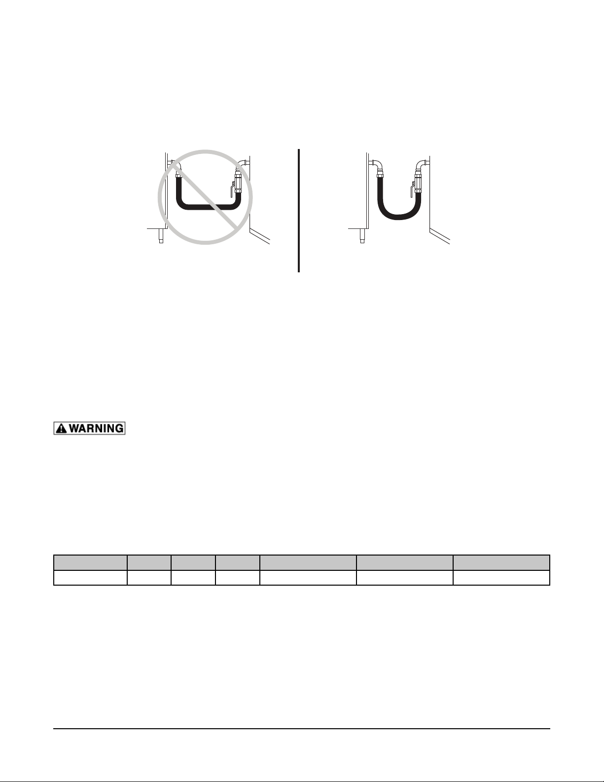
DRAIN CONNECTION
In order to avoid any back pressure in the oven, do not connect solidly to any drain.
The 1" NPT threaded fi tting on the condenser box must be extended a minimum of 12" (305 mm) - maximum
of 72" (1829 mm) away from combi base, to an open air gap type drain. Do not reduce the 1" NPT drain
piping throughout its length. Provide a suitable fl oor sink with a minimum depth of 12" (305 mm). The fl oor
sink is NOT to be directly under the combi and should be at a distance so that steam vapors will not enter
the combi from underneath. The drain should slope down away from the combi ¼" for every foot of drain
pipe length. The drain pipe should be either iron or copper. DO NOT use PVC pipe; PVC pipe may lose
its rigidity or glue may fail.
RIGHT
WRONG
Temperatures in the combi can reach as high as 212°F (l00°C). Local codes
may require that the temperature of drain water be no greater than 140°F
(60°C). At the end of the day, when purging the generator, some provision for
HOSE
HOSE
lowering the water temperature should be provided by the user or installer
to meet this code requirement.
The drain hose for the drip tray should be installed and routed with a constant
decline (Fig. 1).
DRIP TRAY
DRIP TRAY
Fig. 1
GAS SUPPLY CONNECTIONS
Gas supply connections and any pipe joint compound must be resistant to the action of propane
gases.
A ¾" NPT minimum inside diameter gas supply line is required. If quick disconnect devices are used, make
sure it is sized properly for data plate BTU/hr. rating.
Codes require that a manual gas shutoff valve be installed in the gas
line ahead of the combi oven. The gas line must be capable of delivering
gas to the combi oven without excessive pressure drop at the minimum
rate specifi ed on the rating plate.
Gas Input
Natural 5.5" - 10.5" W.C.
Propane 11" - 13" W.C.
MINIMUM RATE
3
/4" NPT
Inadequate gas supply could result in burner noise and poor burner performance.
The proper sizing and installation of the gas connection is important for the machine to operate within
its design specifi cations. In some installations, the gas supply may not be suffi cient enough to allow all
the gas equipment to operate properly at peak loads; or when other equipment with a high BTU/hr. input
requirement is operating. The connection to the machine becomes even more important in this type of
location. Flexible gas connectors with quick disconnect or swivel fi ttings (when used) and gas connectors
beyond the length necessary will reduce the BTU/hr. fl ow capacity to the machine.
– 7 –
Page 8
GAS SUPPLY CONNECTIONS (CONT.)
NOTE: Do not use corrugated stainless steel tubing for commercial gas equipment supply connections.
NOTE: A straight gas connection is the ideal condition for the rated BTU/hr. fl ow capacity of the connector.
If a straight connection is not possible and a fl exible gas connector is used, do not twist, kink or excessively
fl ex the connector beyond a U-shape. Flexing the gas connector as described will restrict gas fl ow or may
damage the connector.
COMBI WALL COMBI WALL
INCORRECT INSTALLATION CORRECT INSTALLATION
Changing a fl exible gas connector may raise the BTU/hr. fl ow capacity enough to allow the machine to
operate within its design specifi cations. (i.e. Removing the quick disconnect fi tting, installing a shorter gas
connector or installing a larger diameter gas connector.)
An alternative may be to move the equipment to a different gas supply location in the kitchen. (i.e. Closer
to the main supply into the kitchen or away from other equipment with high BTU/hr. input requirements.)
The combi oven is equipped with a factory preset pressure regulator. Natural gas pressure regulators are
preset for 5.0" W.C. (1.2 kPa). Propane gas pressure regulators are preset for 10.0" W.C. (2.46 kPa). No
further adjustment should be required. Check gas pressures with a manometer at time of installation to
verify that they agree with the pressures specifi ed.
Prior to lighting, check all joints in the gas supply line for leaks. Use soap and water
solution. Do not use an open fl ame. After piping has been checked for leaks, all piping receiving
gas should be fully purged to remove air.
TESTING THE GAS SUPPLY SYSTEM
1
When gas supply pressure exceeds
/2 psig (3.45 kPa), the oven and its individual shutoff valve must be
disconnected from the gas supply piping system.
When gas supply pressure is
1
/2 psig (3.45 kPa) or less, the oven should be isolated from the gas supply
system by closing its individual manual shutoff valve.
Model Volts Hertz Phase Amps (Max Used) BTU/Hr *Fuse (Amps)
CG10FI 120 60 1 5.0 60,000 1
* Fuse rating is based on electrical standard 125% increase over actual amps used.
FLUE GAS EXHAUST
DO NOT obstruct the fl ow of fl ue gases from the fl ue located on the top of the combi oven. It is recommended
that the fl ue gases be vented to the outside of the building through a ventilation system installed by
qualifi ed personnel. Information on the construction and installation of ventilating hoods may be obtained
from Vapor Removal from Cooking Equipment, NFPA-96 (latest edition) available from the National Fire
Protection Association, Batterymarch Park, Quincy, MA 02269.
– 8 –
Page 9
ELECTRICAL CONNECTION
Appliances equipped with a fl exible electric supply cord are provided with a three-
prong grounding plug. It is imperative that this plug be connected into a properly grounded threeprong receptacle. If the receptacle is not the proper grounding type, contact an electrician. Do not
remove the grounding prong from this plug.
Electrical and grounding connections must comply with the applicable portions of
the National Electrical Code and/or other local electrical codes.
Disconnect electrical power supply and follow lockout / tagout procedures.
The wiring diagram is located on the inside surface of the right side panel as you face the oven. Use
copper wire rated for at least 194°F (90°C) for the connection.
Do not drill a hole in the back panel for electrical connection. Use the strain relief locations on
the lower right side or the knockout on the back panel (Fig. 2). This will allow proper access to components
for service.
STRAIN RELIEF
RIGHT SIDE
KNOCKOUT
REAR
Fig. 2
Do not connect the gas model to the electrical supply until after gas connections
have been made.
Model Volts Hertz Phase Amps (Max Used) Watts *Fuse (Amps)
CE6HD
CE10HD
CE10FD
CE20HD
CE20FD
208
230-240
480
208
230-240
480
208
230-240
480
208
230-240
480
208
230-240
480
60 3
60 3
60 3
60 3
60 3
22.2
20.1-21.9
9.6
44.4
40.2-43.7
19
59.4
53.6-58.4
26
88.8
80.3-87.5
39
103.8
93.8-102.1
45
8000
8000-8700
8000
16000
16000-17400
16000
21400
21400-23300
21400
32000
32000-34800
32000
37400
37400-40700
37400
* Fuse rating is based on electrical standard 125% increase over actual amps used.
30
30
15
60
60
25
80
80
35
125
110
50
150
150
60
NOTE: Single-phase blower motors are used on these ovens so there is no need to check direction of
motor rotation. The fan will rotate in the proper direction.
VENT HOOD
Some local codes may require the Combi oven to be located under an exhaust hood. Information on the
construction and installation of ventilating hoods may be obtained from Vapor Removal from Cooking
Equipment, NFPA Standard No. 96 (latest edition).
BEFORE FIRST USE
Before using the oven for the fi rst time, it must be "burned in" to release any odors that might result from
heating the new surfaces in the oven. Operate the oven at 482°F for 45 minutes in Convection Mode.
– 9 –
Page 10
OPERATION
The oven and its parts are hot. Use care when operating, cleaning or servicing the
oven. The cooking compartment contains live steam. Stay clear when opening door.
DOOR SWITCH
The oven is equipped with a feature that shuts off power to the oven cavity when the door is opened. The
oven will resume cooking once the door is closed.
DOOR OPENING AND CLOSING
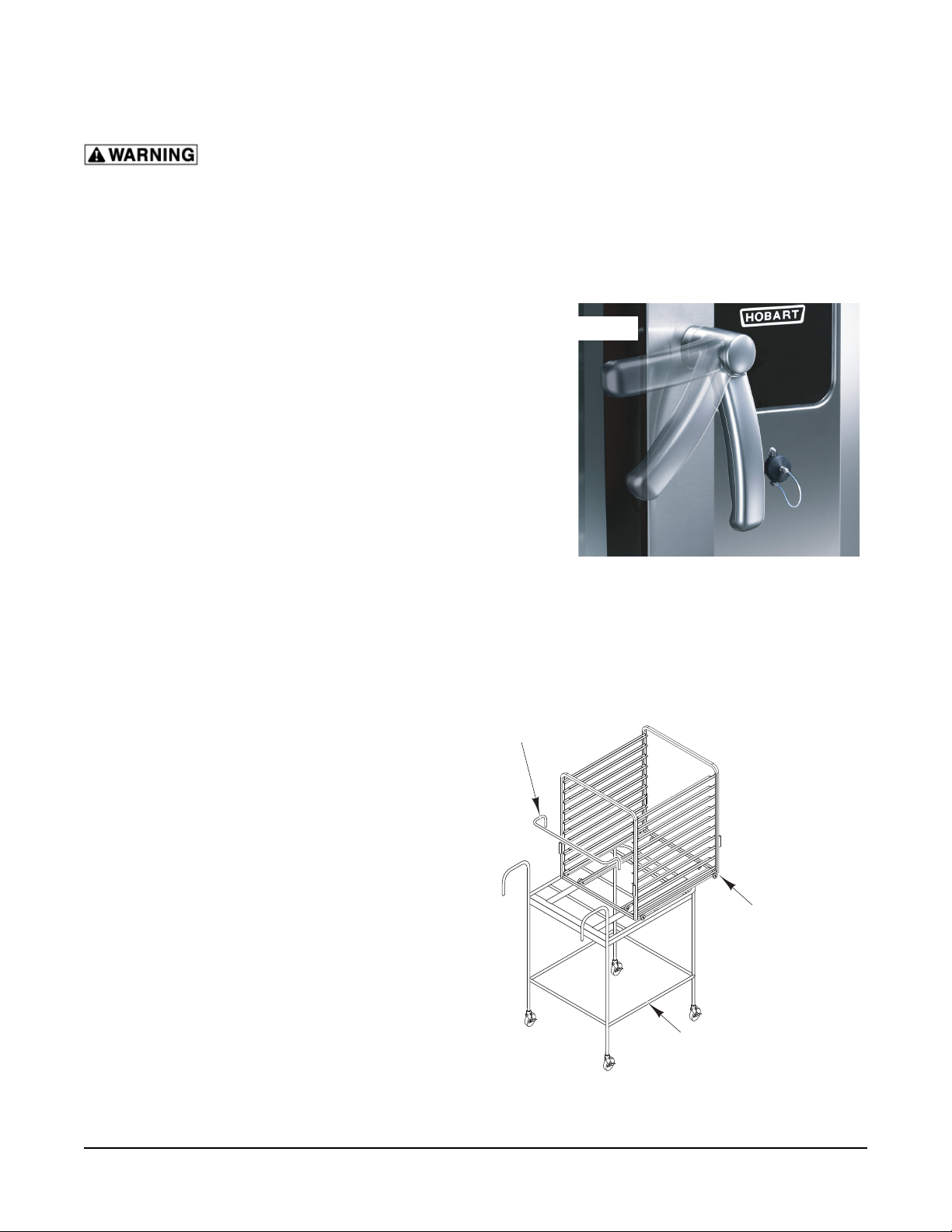
To open the door (Fig. 3), turn the handle to the
horizontal position. Allow a few seconds for steam
to escape before pulling the door open.
To close the door (Fig. 3), position handle in the
horizontal position and push the door closed. Rotate
handle to the vertical position to secure door.
LOADING THE OVEN
Loading 6 or 10 Level Ovens
Place the product to be cooked in suitable containers.
Open the door and slide into the rack guides or
place the containers securely on racks in the oven.
Close the door.
OPEN POSITION
CLOSED POSITION
Fig. 3
Loading 6 or 10 Level Ovens With Landing Table
And Removable Insert
Place removable insert on the landing table. Place
the product to be cooked in suitable containers and
slide into the rack guides or place the containers
securely on racks on the removable insert (Fig. 4).
Place the handle into the removable insert. Open
the door. Position the landing table directly in front
of the open oven cavity. While holding the landing
table in position with one hand, with the other hand,
release the insert and gently roll the removable insert
into the oven cavity. Make sure that the landing
table does not separate from the oven during the
transfer. Remove the handle from the insert and
close the door.
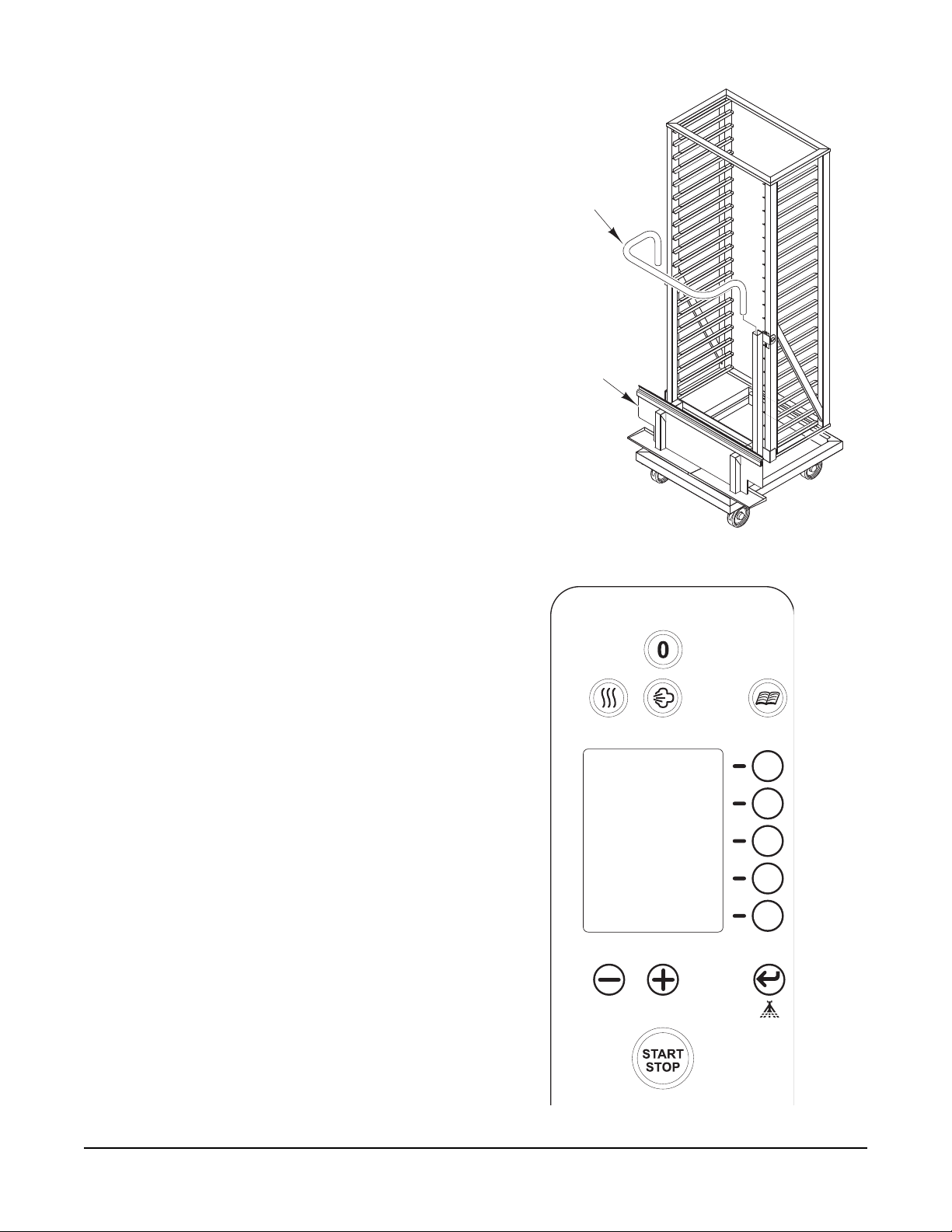
Loading 20 Level Ovens
Place the product to be cooked in suitable containers
and slide into the rack guides or place the containers
securely on racks on the trolley (Fig. 5). Place the
handle into the trolley. Open the door. Line up the
trolley with the trolley slots on the oven and push
the trolley into the oven cavity. Remove the handle
from the trolley and close the door.
HANDLE
REMOVABLE
INSERT
LANDING
TABLE
Fig. 4
– 10 –
Page 11
UNLOADING THE OVEN
Unloading 6 or 10 Level Ovens
Open door partially to allow hot air and steam to
escape. Remove the product from the rack guides
or racks in the oven. Close the door.
Unloading 6 or 10 Level Ovens With Landing
Table And Removable Insert
Open door partially to allow hot air and steam to
escape. Position the landing table (Fig. 4) directly
in front of the oven cavity. Insert the handle into the
removable insert. Using protective gear, carefully roll
the removable insert onto the landing table. Make
sure that the landing table does not separate from
the oven during transfer. Close the door.
Unloading 20 Level Ovens
Open door partially to allow hot air and steam to
escape. Insert the handle into the trolley. Using
protective gear, pull the trolley (Fig. 5) out of the
oven. Close the door.
HANDLE
TROLLEY
COOKING MODES
There are three modes of cooking available with
the Combi Oven.
Convection Mode
Convection Baking involves baking, browning,
roasting, etc. without adding steam or moisture to
the process. Hot air is circulated to maintain even
temperatures throughout the oven.
Steam Mode
Steam cooking is used for stewing, poaching,
and gentle cooking of products cooking in water.
Steam fl ows without pressure into the oven. The fan
circulates the steam to all parts of the oven.
Combi Mode
Combi baking/steaming is used for baking, roasting,
or braising when steam needs to be added to the
oven during a convection baking operation.
CONTROL PANEL
The control panel (Fig. 6) has a screen that displays
to the user the functions in progress. All features
are displayed on the screen and adjusted by using
the buttons on the control panel.
Fig. 5
– 11 –
Fig. 6
Page 12

CONTROL PANEL BUTTONS
ON/OFF Button Press this button to turn the oven on or off.
Convection Mode
Steam Mode
Combi Mode
Program Button
Enter Button
(also used as
Humidity Injector
Button)
Press this button to set the oven to Convection Mode. The
button will illuminate to indicate it has been selected.
Press this button to set the oven to Steam Mode. The button
will illuminate to indicate it has been selected.
Press both buttons to set the oven to Combi Mode. The buttons will illuminate to indicate they have been selected.
Press this button to use an existing program or to write a
new program. (Press and hold 3 seconds to name program.)
Also used to access 10 position timers.
Press this button to confi rm a program selection. When used
during Convection Mode, humidity will be injected into the
oven cavity. (Press and hold 3 seconds to save recipe.)
Minus Button
Plus Button
Selection Line
Button
(total of fi ve)
START/STOP
Button
Press this button to decrease setting feature such as temperature or time.
Press this button to increase setting feature such as temperature or time.
Press these buttons to select the feature displayed in the
control panel next to each Selection Line. These features will
change depending on the screen being displayed.
Press this button to start or stop a program or cooking cycle.
(Press and hold 3 seconds for preheat.)
– 12 –
Page 13

44
EXAMPLE
PH
1/10
DISPLAY SCREEN ICONS
Program Number
(Name)
Cooking Phase
This indicates the current program number, if used.
This indicates the cooking phase in progress. The
oven can be set from 1 to 10 phases.
START
Delayed Preheat
Timer
Temperature
(Delta T)
This icon indicates that the oven has a delayed timer
set for preheat. (Only displayed if no timer has been
selected.)
This icon is selected when adjustment of the temperature is needed.
This icon appears when Delta T is selected. Core
Delta T
probe readings control rising set temperatures on a set
scale.
Timer
(Core Probe)
Core Probe
This icon is selected when adjustment of the timer is
needed.
This icon appears when the core probe is being used
to monitor the internal temperature of a product.
This icon indicates that the oven cavity vent is open
Vent Open/Closed
or closed. Press the Selection Line Button next to the
icon to toggle. (Convection Mode only.)
Humidity This icon indicates that humidity is present in the oven.
An arrow may appear next to the humidity icon to in-
Humidity Arrow
dicate whether more or less humidity is needed in the
oven.
3
Fan Speed
Manual Operation/
No Timer
Cool Down
This icon indicates the fan speed in the oven. The
value range is 1 to 4.
This icon is used to show that a function is in continuous mode. It is commonly used when the timer is not
set or when the 10 position timer function is used.
This icon appears when the oven is set to cool down
from high temperatures.
These icons remind the operator to perform a service
500H
Service/Hours
Remaining
on the machine such as delime of the cavity or routine
service check. The machine will continue to operate
regardless of the number displayed.
Barcode
This icon appears when the oven has a program
assigned to a specifi c barcode.
– 13 –
Page 14

INITIAL START-UP
When the machine is connected to electrical power, the display screen will show the current time and date
as set in the oven and the countdown for service/deliming. The internal clock should be set at this time.
SETTING THE INTERNAL CLOCK
1. Press and hold the Selection Line Button next
to the time and date. The hour portion of the
time will fl ash.
2. Use the Plus/Minus Buttons to adjust the
hour.
3. Press the Enter Button. The minute portion of
the time will fl ash.
4. Repeat steps 2 and 3 until the time and date
are set.
NOTE: Press the Selection Line Button below the
time and date to toggle the time between 12 hour
and 24 hour time.
SETTING THE TEMPERATURE
1. Select the cooking mode by pressing the
Convection, Steam or Convection and Steam
(Combi) Button(s).
2. Press the Selection Line Button next to the
Temperature icon. The icon will be highlighted
to indicate that it has been selected and the
set temperature will be shown.
11:28 AM 05/19/07
500H
PH
1/1
110
°F
HOUR
FLASHING
11:28
PRESS TO
CHANGE TO
24 HOUR TIME
START
3. Use the Plus/Minus Buttons to adjust the
temperature. After a few seconds the
Temperature icon will change contrast and
the set oven cavity temperature will be
displayed.
NOTE: Press and hold the Selection Line Button
next to the Temperature icon to view the current
oven temperature.
NOTE: The degree symbol next to the temperature
will be solid when the oven is heating. The symbol
will be open when the oven temperature equals the
set temperature.
– 14 –
3
Page 15

SETTING THE TIMER
1. Select the cooking mode by pressing the
Convection, Steam or Convection and Steam
(Combi) Button(s).
2. Press the Selection Line Button next to the
Timer icon. The icon will be highlighted to
indicate that it has been selected and the set
timer will be shown.
3. Use the Plus/Minus Buttons to adjust the timer.
After a few seconds the Timer icon will change
contrast and the set timer will be displayed.
NOTE: The Hand icon indicates the timer is in
continuous mode and no timer is used or that the
10 position timer function is in use. (See Using the
10 Position Timer.)
SETTING THE HUMIDITY
1. Select Combi Mode by pressing the Convection
Button and Steam Button.
PH
1/1
350
START
°F
3
2. Press the Selection Line Button next to the
Humidity icon. The icon will be highlighted to
indicate that it has been selected and the set
humidity will be shown.
3. Use the Plus/Minus Buttons to adjust the
humidity. After a few seconds the Humidity
icon will change contrast and the set humidity
will be displayed.
SETTING THE VENT POSITION
1. Select Convection Mode by pressing the
Convection Button.
2. Press the Selection Line Button next to the Vent
Position icon. The icon will toggle between the
open and closed position.
PH
1/1
350
01:25
5
PH
1/1
350
01:25
°F
°F
3
VENT
OPEN
– 15 –
3
Page 16

SETTING THE FAN SPEED
1. Select the cooking mode by pressing the
Convection, Steam or Convection and Steam
(Combi) Button(s).
2. Press the Selection Line Button next to the
Fan Speed icon. The icon will be highlighted
to indicate that it has been selected.
3. Use the Plus/Minus Buttons to adjust the fan
speed. After a few seconds the Fan Speed
icon will change contrast.
FAST COOL DOWN
This feature is used to cool down the oven quickly.
It may be necessary to do this when changing from
a high temperature operation to one that requires
lower temperatures.
PH
1/1
350
01:25
PH
1/1
°F
FAN SPEED
1 TO 4
3
2
1. Press the Selection Line Button next to the
Timer icon. The icon will be highlighted to
indicate that it has been selected.
2. Press and hold the Minus Button until the Cool
Down icon appears.
3. Press the Selection Line Button next to the
Temperature icon. The icon will highlight to
indicate that it has been selected and the set
cool down temperature will be shown.
4. Use the Plus/Minus Buttons to adjust the oven
to the desired cool down temperature.
5. Press the START/STOP Button.
NOTE: Choosing another mode will stop above
process.
110
°F
4
– 16 –
Page 17

SELECTING THE COOKING MODE
After selecting one of the cooking modes, the default temperature for that cooking mode is displayed. The
oven cavity lights will be on (only if the door is closed).
PREHEATING THE OVEN
1. Set the cooking mode or use a program.
2. Press and hold the START/STOP Button for 3 seconds. The buzzer will sound and the oven will
automatically preheat to the correct cooking temperature. The timer, if set, will not count down.
When the set temperature is reached the buzzer will sound again to indicate the oven is ready to be
loaded.
3. Load the oven and press the START/STOP Button.
USING CONVECTION MODE
1. If the screen is blank (sleep mode), turn on
the oven by pressing the ON/OFF Button.
2. Press the Convection Button to select
convection mode. The button will illuminate
to indicate it has been selected.
PH
3. Set the oven temperature.
1/1
4. Set the timer.
5. Set the vent position.
6. Set the fan speed.
NOTE: Preheating the oven is recommended.
7. Load the oven and press the START/STOP
Button.
8. If called for in the recipe, press the Humidity
Injector Button to add a short blast of steam
to the cavity.
9. When the timer has counted down, the buzzer
will sound for 5 seconds and the oven cavity
lights will fl ash.
10. Press the START/STOP Button to silence the
buzzer and end the cooking session.
11. Unload the oven.
350
01:17
°F
2
– 17 –
Page 18

USING STEAM MODE
1. If the screen is blank (sleep mode), turn on
the oven by pressing the ON/OFF Button.
2. Press the Steam Button to select steam mode.
The button will illuminate to indicate it has been
selected.
3. Set the oven temperature.
PH
1/1
4. Set the timer.
5. Set the fan speed.
NOTE: Preheating the oven is recommended.
6. Load the oven and press the START/STOP
Button.
7. When the timer has counted down, the buzzer
will sound for 5 seconds and the oven cavity
lights will fl ash.
8. Press the START/STOP Button to silence the
timer and end the cooking session.
9. Unload the oven.
USING COMBI MODE
1. If the screen is blank (sleep mode), turn on
the oven by pressing the ON/OFF Button.
2. Press the Convection and Steam Button to
select combi mode. Both buttons will illuminate
to indicate they have been selected.
3. Set the oven temperature.
212
00:38
PH
1/1
°F
2
4. Set the timer.
5. Set the humidity level.
6. Set the fan speed.
NOTE: Preheating the oven is recommended.
7. Load the oven and press the START/STOP
Button.
8. When the timer has counted down, the buzzer
will sound for 5 seconds and the oven cavity
lights will fl ash.
9. Press the START/STOP Button to silence the
timer and end the cooking session.
10. Unload the oven.
– 18 –
350
00:47
5
°F
4
Page 19

TEMPERATURE PROBE
The probe temperature defi nes the fi nal temperature of the product for any cooking phase. The oven
cooking cycle stops when the product temperature reaches the probe temperature setting. Total cooking
time is not known or entered when using the probe.
There are two ways to control the oven temperature when using the probe:
• Setting the oven temperature at a constant value. The oven maintains the set temperature
throughout the cook cycle and ends when the product reaches the probe temperature
setting.
• Setting the probe using Delta T. The oven temperature gradually increases as the internal
temperature of the product increases, always maintaining the oven at a set number of
degrees warmer than the product. Delta T can provide a slow cooking process that allows
the product to reach the required fi nal internal temperature with maximum product yield.
The graph below shows the two ways of controlling the oven temperature when using the core probe. The
"100°F" value for Delta T is used to show how the oven works and is not typical of any particular cooking
program.
Final Oven Temperature
265°F
Initial Oven Temperature
140°F
Final Product Temperature
165°F
Initial Product Temperature
40°F
USING THE PROBE
WITH DELTA T
Oven Temperature
100°F=
Product Temperature
TEMPERATURE
TIME TIME
COOKING WITH PROBE AND
T
CONSTANT OVEN TEMPERATURE
265°F
Constant Oven Temperature
T
165°F
40°F
Product Temperature
DONE
TEMPERATURE
DONE
– 19 –
Page 20

USING THE PRODUCT TEMPERATURE PROBE
Setting the Cooking Core Probe Temperature
1. Insert the pointed end of the core probe into
the product so that the tip is approximately in
the middle of the product to be cooked.
2. Load the product into the oven.
3. Run the probe cable out the side of the door
opening and close the door.
4. Connect the temperature probe (Fig. 7) to the
connector below the control panel.
5. Press and hold the Selection Line Button next
to the Timer icon. The icon will change to the
Core Probe icon and display the set core probe
temperature.
6. Press the Selection Line Button next to the
Core Probe icon. The icon will be highlighted
to indicate that it has been selected.
7. Use the Plus/Minus Buttons to adjust the core
probe set temperature. After a few seconds the
Core Probe icon will change contrast and the
current temperature measured by the probe
will be displayed.
CORE PROBE
PH
1/1
350
°F
START
3
Fig. 7
CORE PROBE
ICON
8. Set all other cooking mode settings.
9. Press the START/STOP Button.
Setting Delta T
1. Select the cooking mode by pressing the
Convection Button and/or Steam Button.
2. Press and hold the Selection Line Button
next to the Temperature icon. The icon will
change to the Delta T icon and display the
set temperature difference between the oven
cavity and the core probe.
3. Press the Selection Line Button next to the
Delta T icon. The icon will be highlighted to
indicate that it has been selected.
4. Use the Plus/Minus Buttons to adjust the Delta
T set point temperature. After a few seconds
the Delta T icon will change contrast and
the current oven cavity temperature will be
displayed.
5. Set the core probe temperature by following
the instruction above.
PH
1/1
170
3
DE LTA T
ICON
START
°F
6. Set all other cooking mode settings.
7. Press the START/STOP Button.
– 20 –
Page 21

USING THE 10 POSITION TIMER
NOTE: The 10 position timers are only available in
standard cooking modes. This feature can not be
used with a cooking program, delta T, core probe
or standard timer.
1. Select the cooking mode by pressing the
Convection, Steam or Convection and Steam
(Combi) Button(s).
2. Set the oven temperature, fan speed, humidity
level and/or vent position.
3. Press the START/STOP Button.
4. Press the Program Button to enter the 10
position timer mode. (The Program Button
will fl ash and the screen will change to show
10 position timers.)
5. Press the Selection Line Button next to the
timer position to be set. The position timer
will be highlighted to indicate that it has been
selected.
NOTE: Each Selection Line Button controls two
positions. Press the button to toggle between each
timer position.
6. Use the Plus/Minus Buttons to adjust the timer
position setting. After a few seconds the timers
will begin countdown.
NOTE: Each position timer can be set from 0 to 59
minutes.
7. When a timer position reaches 0, the buzzer will
sound for fi ve seconds and the timer position
will fl ash.
PH
1/1
350
350
PROGRAM
BUTTON
(FLASHING)
START
°F
3
PROGRAM
BUTTON
(FLASHING)
01 15
02 15
03 15
04 10
05 10
06 10
07 05
09 01
08 05
10 20
3
03 15
04 10
TIMER
POSITION 03
SELECTED
8. Open door and remove the product from that
position.
NOTE: The other positions continue to countdown
while the door is open. Remove product quickly and
close door.
NOTE: If the START/STOP Button is pressed while
position timers are active, each timer will pause
and not continue countdown until the START/
STOP Button is pressed again. The START/STOP
Button will illuminate to indicate timer positions are
active.
NOTE: Cooking settings can be modifi ed while
position timers are active. Press the Program Button
and adjust the desired cooking settings. The timers
will continue to countdown while adjusting the
cooking settings.
– 21 –
Page 22

WRITING A COOKING PHASE
It is possible to link up to 10 cooking phases without
using the program function.
1. Select the cooking mode by pressing the
Convection Button and/or Steam Button.
2. Set cooking temperature or Delta T
temperature.
3. Set cooking time or use the core probe. The
Cooking Phase will indicate 1 of 1.
4. Set the vent position or the humidity level,
depending on the cooking mode being
used.
5. Set the fan speed.
6. Press the top Selection Line Button to add a
phase. The Cooking Phase will indicate that
is ready for the next phase 2 of 2.
7. Repeat steps 1 through 6 for each phase.
NOTE: Press the top Selection Line Button to review
the cooking phases.
8. Load product, close door and press the START/
STOP Button to begin cooking phases.
ERASING A COOKING PHASE
1. Press the top Selection Line Button until the
phase to be erased is displayed.
PH
1/1
350
01:17
°F
PH
1/1
2
2. Press and hold the top Selection Line Button.
The buzzer will sound and the phase will be
erased.
NOTE: Once a phase is erased the remaining
phases automatically renumber.
PH
2/2
350
00:47
85
PH 2/2
°F
4
– 22 –
Page 23

WRITING A COOKING PROGRAM
It is possible to write and store up to 100 cooking
programs with a maximum of 10 phases each.
NOTE: The oven is also equipped to use an optional
HCPC-HACCP recording system to facilitate fast,
easy and accurate data management via wireless
communication to a PC. Contact your local Hobart
representative for more information.
1. Press the Program Button to select program
mode. The button will illuminate to indicate
it has been selected and will display recipe
"00".
2. Use the Plus/Minus Buttons to select
the program number that will identify this
program.
3. Input all cooking phases. The program number
will blink to indicate that it has not been
stored.
4. Press and hold the Program Button. The display
will change and show the available characters
that can be used to name the program.
55
PH
2/2
350
01:17
°F
55
PROGRAM
NUMBER
2
5. Use the Plus/Minus Buttons to place the
fl ashing cursor over the character to be
used.
6. Press the Enter Button to add the character
to the name. The characters will be added to
the right of the program number on the display
screen.
7. Repeat steps 5 and 6 to add more characters
to the program name.
NOTE: Use the top Selection Line Button next to the
arrow icon to erase a character or to backspace.
8. After the program has been named, press and
hold the Enter Button to store the name with
the program number. The buzzer will sound
and the program number will stop blinking to
indicate that the program has been stored.
NOTE: A program can also be made after a cooking
cycle has been run. Press the Program Button, use
the Plus/Minus Buttons to navigate to a number to
store the program and press the Enter Button. Use
the steps above to name the program.
55 EXAMPLE
6308541402
0 1 2 3 4 5 6 7 8 9 - .
ABCDE FGHIJKLM
NOPQRSTUVWXYZ
55
PROGRAM
NUMBER
– 23 –
Page 24

MODIFYING A COOKING PROGRAM
1. Press the Program Button to select program
mode. The button will illuminate to indicate it
has been selected.
2. Use the Plus/Minus Buttons to select the
program to be modifi ed.
3. Modify the desired cooking phases. The
program number will blink to indicate that it
has not been stored.
NOTE: A modifi ed program can be run before
storing. After the program has run, it can then be
stored. It is not possible to insert a phase into a
program.
4. Press and hold the Enter Button. The buzzer
will sound and the program number will stop
blinking to indicate that the program has been
stored.
REVIEWING A COOKING PROGRAM
1. Press the Program Button to select program
mode. The button will illuminate to indicate it
has been selected.
55 EXAMPLE
PH
2/2
325
02:15
°F
55
PROGRAM
NUMBER
4
2. Use the Plus/Minus Buttons to select the
program number to be reviewed. The screen
will display the fi rst phase of the program.
3. Press the top Selection Line Button to scroll
through the phases of the program.
4. Press the Selection Line Button next to the
temperature icon to view the set temperature
on each phase.
5. Press the START/STOP Button to view total
cooking time for the selected program.
NOTE: The total cooking time for all phases will be
displayed unless one of the phases uses the core
probe or continuous timer mode.
ERASING A COOKING PROGRAM
1. Press the Program Button to select program
mode. The button will illuminate to indicate it
has been selected.
2. Use the Plus/Minus Buttons to select the
program to be erased.
3. Press and hold the Enter Button. The buzzer
will sound and the program will be erased.
– 24 –
Page 25

USING A COOKING PROGRAM
1. Press the Program Button to select program
mode. The button will illuminate to indicate it
has been selected.
2. Use the Plus/Minus Buttons to select the
program number to be used. The screen will
display the fi rst phase of the program.
3. Press the START/STOP Button to start the
program. The total time remaining will be
displayed and the buzzer will sound for one
second at the completion of each phase.
55 EXAMPLE
PH
2/2
325
02:15
°F
55
PROGRAM
NUMBER
NOTE: The total cooking time for all phases will be
displayed unless one of the phases uses the core
probe or continuous timer mode.
SETTING A PREHEAT DELAYED START
It is possible to program the oven to start preheating
at any set time. This feature can be used to conserve
energy and maximize effi ciency.
1. Select a cooking mode and set the preheat
temperature.
2. Press the Selection Line Button next to the
Delayed Timer icon. The actual time will be
displayed and the hour portion of the preheat
time will be fl ashing.
3. Use the Plus/Minus Buttons to adjust the
hour.
4. Press the Enter Button. The minute portion of
the time will fl ash.
5. Use the Plus/Minus Buttons to adjust the
minute.
PH
1/1
350
11:1 5 AM
12:30 PM
°F
START
4
ACTUAL TIME
11:15 AM
12:30 PM
SET TIME
6. Press the START/STOP Button.
3
– 25 –
Page 26

ADD A BARCODE TO A PROGRAM (IF OPTIONAL
BARCODE SCANNER WAS ORDERED)
1. Press the Program Button to select program
mode.
2. Use the Plus/Minus Buttons to select the
program number to add a barcode.
3. Press and hold the Program Button. The display
will change and show the available characters
that can be used to name the program.
4. Press the Selection Line Button next to Add
Barcode icon. The icon will be highlighted to
indicate that it has been selected.
5. Scan the barcode of the product within 10
seconds (Fig. 8). The scanned barcode will
now be displayed in a number code beneath
the program number and name.
6. Press and hold the Enter Button to store the
barcode with the program number. The buzzer
will sound and the program number will stop
blinking to indicate that the program has been
stored.
55 EXAMPLE
6308541402
0 1 2 3 4 5 6 7 8 9 - .
ABCDE FGHIJKLM
NOPQRSTUVWXYZ
PROGRAM
BUTTON
55
PROGRAM
NUMBER
DELETE
BARCODE
ADD
BARCODE
ENTER
BUTTON
NOTE: A barcode can only be associated with one
program. When adding a barcode, if it is already
associated with a recipe, the icon will change to a
stop icon and will display the program number that
barcode is associated to.
REMOVE A BARCODE FROM A PROGRAM
1. Press the Program Button to select program
mode.
2. Use the Plus/Minus Buttons to select the
program number to remove a barcode.
3. Press and hold the Program Button. The display
will change and show the available characters
that can be used to name the program.
4. Press and hold the Selection Line Button
next to Remove Barcode icon. The barcode
number will erase to indicate that the barcode
has been removed.
5. Press and hold the Enter Button to store the
program without a barcode.
55 EXAMPLE
6308541402
0 1 2 3 4 5 6 7 8 9 - .
ABCDE FGHIJKLM
NOPQRSTUVWXYZ
26
BARCODE
EXISTS ON
PROGRAM
No. 26
– 26 –
Page 27

USING THE SCANNER
The oven and its parts are hot.
Use care when operating, cleaning or servicing
the oven. The cooking compartment contains
live steam. Stay clear when opening door.
1. Scan barcode of product (Fig. 8). The oven
will activate the program associated and will
start automatically in preheat mode.
2. Once the oven is preheated, load the oven
and close the door. Once the door is shut, the
oven will start the timer and begin.
NOTE: If the combi is in use (start button activated);
scanning a barcode will not change operation.
NOTE: The optional barcode scanner comes
standard with a PC software program. This program
enables custom barcodes to be created and used
in conjunction with the methods described above.
Instructions for this method are in a separate
document.
Fig. 8
COMBI OVEN BLUETOOTH CAPABILITIES
The combi oven is equipped with a Bluetooth® device
that is always active. Typical range for connectivity
is approximately 10 feet.
The main use of this capability is transferring
programs to and from the oven. To transfer fi les,
a Bluetooth capable device is required such as a
phone, PDA, or laptop computer.
Pair with Bluetooth Enabled Device
1. Ensure Bluetooth is enabled on the device to
be paired with the oven.
2. In the Bluetooth setup application, click OK.
3. Search for devices (Fig. 9).
4. Select the device to pair with (Fig. 10).
5. Enter numeric passkey for the device. The
passkey is "0000". The device should now be
paired with the oven (Fig. 11).
Searching for devices
2 found
Stop
Fig. 9
Select device
F00078085596f3
Cancel
Fig. 10
Enter numeric passkey for
F00078085596f3:
****
Fig. 11
– 27 –
Page 28

Sending recipes via Bluetooth
All fi les to be transferred to the oven must be on
the device before pairing with the oven. Use the
software provided with the scanner to create recipes.
To get the fi les on the Bluetooth device, refer to the
instructions provided with the Bluetooth device in
use. Contact your local Hobart representative for
more information.
Folder
US Example Recipes.jpg
1. Ensure Bluetooth is activated on device and
already paired with combi.
2. In the media application, select pictures.
3. Navigate to the recipe fi le to be transferred.
4. Highlight the fi le (Fig. 12).
5 Press the Menu key.
6. Click Send Using Bluetooth (Fig. 13).
7. Click a Bluetooth enabled device.
8. Click Send (Fig. 14).
9. A progress bar will display and the oven
will make an audible sound to confi rm fi le
transfer.
NOTE: If an "Unable to connect" error occurs, verify
that Bluetooth is enabled on the device and that the
device is paired with the oven.
Fig. 12
New Folder
Folder
Delete
Copy
Move
Rename
Properties
Download Images
Send As Email
Send Using Bluetooth
Receive Using Bluetooth
US Example Recipes.jpg
Set As Caller ID
Fig. 13
Folder
Select a device:
F00078085596f3
– 28 –
US Example Recipes.jpg
Fig. 14
Page 29

MAINTENANCE
Disconnect electrical power supply and follow lockout / tagout procedures.
Fluorescent lamp in display panel contains a small amount of mercury. Please dispose of
according to local, state or federal laws.
SERVICE ADJUSTMENTS
The Combi Oven default settings can be customized to fi t your own personal needs using service parameter
setup. Contact your local Hobart Service offi ce for any adjustments needed on this equipment.
DOOR LOCKING AND GASKET INSPECTION
During oven operation, if air or steam blows out from the top, sides, or underneath to door, the door may
need adjustment. Inspect the door locking movement and the door gasket.
Door Locking Inspection
When closing door, the locking action should be smooth with no binding and not require excessive force
to turn the door handle. The door must exert enough pressure on the gasket to prevent steam from exiting
the oven cavity. If the door locking is extremely tight, contact your local Hobart
Service offi ce for any repairs or adjustments needed on this equipment.
Door Gasket Inspection
Visually inspect the door gasket for cracks, splits, and missing sections.
Using a dollar bill or a strip of plain paper approximately the same size, position
the paper between door and gasket then close the door. The paper should
STOP
fi t tightly and not be easily removed when pulled. Check tightness near the
corners and in the center locations at the left, top and right sides of door. If the
door gasket is not sealing properly, contact your local Hobart Service offi ce for
any repairs or adjustments needed on this equipment.
SERVICE AND PARTS INFORMATION
Contact your local Hobart Service offi ce for any repairs or adjustments needed
on this equipment.
SHUTTING DOWN THE OVEN
1. Press the ON/OFF Button. The display screen will show the Cleaning and Shutdown icons.
2. Press the Selection Line Button next to the icon to be performed.
DISPLAY SCREEN CLEANING AND SHUTDOWN ICONS
STOP
Stop Only Select this feature if the oven will be shutdown and not cleaned.
STOP
Stop and Drain
Stop and Do Not
STOP
Drain
Select this feature if the oven boiler (if equipped) should be
drained before shutdown.
Select this feature if the oven boiler (if equipped) should not be
drained before shutdown.
Manual Clean Cycle Select this feature if the oven cavity is to be cleaned manually.
Auto Clean Cycle Select this feature if the oven cavity is to be cleaned automatically.
– 29 –
Page 30

STAINLESS STEEL EQUIPMENT CARE AND CLEANING
(Supplied courtesy of NAFEM. For more information, visit their web site at www.nafem.org)
Contrary to popular belief, stainless steels ARE susceptible to
rusting.
Corrosion on metals is everywhere. It is recognized quickly on iron
and steel as unsightly yellow/orange rust. Such metals are called
“active” because they actively corrode in a natural environment when
their atoms combine with oxygen to form rust.
Stainless steels are passive metals because they contain other metals,
like chromium, nickel and manganese that stabilize the atoms. 400
series stainless steels are called ferritic, contain chromium, and are
magnetic; 300 series stainless steels are called austenitic, contain
chromium and nickel; and 200 series stainless, also austenitic,
contains manganese, nitrogen and carbon. Austenitic types of
stainless are not magnetic, and generally provide greater resistance
to corrosion than ferritic types.
With 12-30 percent chromium, an invisible passive fi lm covers the
steel’s surface acting as a shield against corrosion. As long as the
fi lm is intact and not broken or contaminated, the metal is passive
and stain-less. If the passive fi lm of stainless steel has been broken,
equipment starts to corrode. At its end, it rusts.
Enemies of Stainless Steel
There are three basic things which can break down stainless steel’s
passivity layer and allow corrosion to occur.
1. Mechanical abrasion
2. Deposits and water
3. Chlorides
Mechanical abrasion means those things that will scratch a steel
surface. Steel pads, wire brushes and scrapers are prime examples.
Water comes out of the faucet in varying degrees of hardness.
Depending on what part of the country you live in, you may have hard
or soft water. Hard water may leave spots, and when heated leave
deposits behind that if left to sit, will break down the passive layer and
rust stainless steel. Other deposits from food preparation and service
must be properly removed.
Chlorides are found nearly everywhere. They are in water, food
and table salt. One of the worst chloride perpetrators can come from
household and industrial cleaners.
So what does all this mean? Don’t Despair!
Here are a few steps that can help prevent stainless steel rust.
1. Use the proper tools.
When cleaning stainless steel products, use non-abrasive tools.
Soft cloths and plastic scouring pads will not harm steel’s passive
layer. Stainless steel pads also can be used but the scrubbing
motion must be in the direction of the manufacturers’ polishing
marks.
2. Clean with the polish lines.
Some stainless steel comes with visible polishing lines or “grain.”
When visible lines are present, always scrub in a motion parallel
to the lines. When the grain cannot be seen, play it safe and use
a soft cloth or plastic scouring pad.
3. Use alkaline, alkaline chlorinated or non-chloride
containing cleaners.
While many traditional cleaners are loaded with chlorides, the
industry is providing an ever-increasing choice of non-chloride
cleaners. If you are not sure of chloride content in the cleaner
used, contact your cleaner supplier. If your present cleaner
contains chlorides, ask your supplier if they have an alternative.
Avoid cleaners containing quaternary salts; it also can attack
stainless steel and cause pitting and rusting.
4. Treat your water.
Though this is not always practical, softening hard water can do
much to reduce deposits. There are certain fi lters that can be
installed to remove distasteful and corrosive elements. To insure
proper water treatment, call a treatment specialist.
5. Keep your food equipment clean.
Use alkaline, alkaline chlorinated or non-chloride cleaners
at recommended strength. Clean frequently to avoid buildup of hard, stubborn stains. If you boil water in stainless steel
equipment, remember the single most likely cause of damage
is chlorides in the water. Heating cleaners that contain chlorides
have a similar effect.
6. Rinse, rinse, rinse.
If chlorinated cleaners are used, rinse and wipe equipment and
supplies dry immediately. The sooner you wipe off standing water,
especially when it contains cleaning agents, the better. After
wiping equipment down, allow it to air dry; oxygen helps maintain
the stainless steel’s passivity fi lm.
7. Never use hydrochloric acid (muriatic acid) on stainless
steel.
8. Regularly restore/passivate stainless steel.
Job Cleaning Agent Comments
Routine cleaning Soap, ammonia,
Fingerprints
and smears
Stubborn stains
and discoloration
Grease and fatty
acids, blood,
burnt-on foods
Grease and Oil Any good
Restoration/
Passivation
Review
1. Stainless steels rust when passivity (fi lm-shield) breaks down
as a result of scrapes, scratches, deposits and chlorides.
2. Stainless steel rust starts with pits and cracks.
3. Use the proper tools. Do not use steel pads, wire brushes or
scrapers to clean stainless steel.
4. Use non-chlorinated cleaners at recommended concentrations.
Use only chloridefree cleaners.
5. Soften your water. Use fi lters and softeners whenever
possible.
6. Wipe off cleaning agent(s) and standing water as soon as
possible. Prolonged contact causes eventual problems.
To learn more about chloride-stress corrosion and how to prevent it,
contact the equipment manufacturer or cleaning materials supplier.
Developed by Packer Engineering, Naperville, Ill., an independent
testing laboratory.
detergent, Medallion
Arcal 20, Lac-O-
Nu Ecoshine
Cameo, Talc, Zud,
First Impression
Easy-off, DeGrease
It Oven Aid
commercial
detergent
Benefi t, Super
Sheen
Apply with soft
cloth or sponge.
Provides barrier fi lm
Rub in direction
of polish lines.
Excellent removal
on all fi nishes
Apply with soft
cloth or sponge.
– 30 –
Page 31

CLEANING
The oven and its parts are hot. Always allow the oven to cool before cleaning.
The Combi oven must be cleaned regularly in order to maintain performance. The automatic clean function
provides a quick and easy way to keep the oven cavity clean. However, periodic cleaning is required to
the exterior to ensure continued safe, reliable operation. Review the cleaning instruction provided.
The oven has considerable amounts of stainless steel that will require proper care. Review the section
Stainless Steel Equipment Care and Cleaning for additional information about proper care for stainless
steel.
Daily Cleaning
1. Remove any large pieces of food that may be in the oven cavity before starting a cleaning cycle.
2. Perform one of the cleaning cycles.
3. Clean the door gasket with a soft, clean, damp cloth after every cleaning cycle. This will ensure a
long life for the gasket.
4. Do not use cleaners containing grit, abrasive materials,
bleach, harsh chemicals, chlorides, acidic based detergents
or chlorinated cleaners.
5. Do not use steel wool on stainless steel or glass surfaces.
6. Be cautious with new or improved cleaning formulas; use only
after being well tested in an inconspicuous place.
7. Clean the door glass exterior.
Weekly Cleaning
1. Clean any air vents on the exterior of the oven. Dust can
collect on the vent openings. Clogged vents can cause oven
components to overheat.
2. Remove wire racks and wipe the rack support rails.
Changing the Chemical Bottle (Fig. 15)
1. Remove cap and tube from empty bottle.
2. Place tube with fi lter and weight into new bottle until it reaches the bottom
of the bottle.
3. Slide cap down the tube and tighten cap on the bottle.
Quick Rinse Cycle
TUBE
Fig. 15
95
CAP
(With Hole)
FILTER
(With Weight)
°F
NOTE: The quick rinse cycle is an automatic cycle that does not use detergent.
This feature can be used to give the oven cavity a quick rinse between product
uses.
1. Press the Selection Line Button next to the Auto Clean Cycle icon.
2. Use the Minus Button to select "0" detergent to be used.
3. Press and hold the Minus Button until an "R" appears instead of a "0".
4. Press the START/STOP Button to begin the quick rinse cycle.
– 31 –
R
Page 32

Manual Clean Cycle
1. Press the Selection Line Button next to the Manual Clean Cycle
icon.
2. Press the START/STOP Button to begin the clean cycle. The buzzer
will sound to indicate that the interior is ready to be sprayed with an
appropriate detergent.
3. Open the door and spray the detergent.
4. Close the door, the clean cycle will restart and end with the appropriate
rinse of the cavity.
Automatic Clean Cycle
NOTE: Before using the auto clean cycle, make sure that the detergent
pump tube is inserted correctly into the detergent container and that enough
detergent is available.
1. Press the Selection Line Button next to the Auto Clean Cycle icon.
2. Use the Plus/Minus Buttons to select the clean cycle time and amount
of detergent to be used. The time and detergent values are preset.
Select the preset value depending on the level of cleaning needed.
3. Press the START/STOP Button to begin the clean cycle.
STOP
NOTE: There may not be any visible signs that the automatic clean cycle has begun. This will depend
on the temperature of the oven cavity.
Preset Automatic Clean Cycle Values
(times may vary depending on automatic cool down)
Level Detergent Dose Time Level Detergent Dose Time Level Detergent Dose Time
0 0 0:25 3 15 0:47 6 30 1:12
1 5 0:30 4 20 0:55 7 35 1:20
2 10 0:38 5 25 1:04 8 45 1:29
Descaling the Boiler
1. Press the ON/OFF Button and press the Selection Line Button next
to the Stop and Drain icon. The boiler will drain.
2. Fill the boiler with white vinegar or similar descaling product using
the steam inlet at the top right hand side of the cavity. Use 5 quarts
for 6-Pan ovens, 6 quarts for 10-Pan ovens, or 10 quarts for 20-Pan
ovens.
3. Select Steam Mode and wait 30 to 45 minutes. Do not start the steam
cycle.
4. Press the ON/OFF Button and press the Selection Line Button next
to the Stop and Drain icon. The boiler will drain.
5. Select Steam Mode again to rinse the boiler. Do not start the steam
cycle.
6. Select a clean cycle to fi nalize the descaling process.
– 32 –
Page 33

Deliming the Cavity
Oven cavity deliming should be done on a regular basis. The frequency depends on oven use, quality
of the local water supply and what type of water treatment system is used. Even with the use of a water
treatment system, periodic deliming of the oven cavity is still required. If lime scale build up becomes
visibly noticeable, then the oven cavity deliming should be performed.
Deliming should only be performed on a cool oven after a clean cycle has occurred.
NOTE: All components inside the oven cavity, such as the heating elements, racks, rack guides and interior
glass, can be sprayed with white vinegar or a deliming product.
1. Spray the entire oven cavity with white vinegar (full strength) and let it stand for 15 minutes. Or use
a deliming product. When using a deliming product other than white vinegar, follow the directions
on the product label.
2. Close the oven door.
3. Rinse the oven cavity using the automatic clean cycle and set the cycle to "0".
– 33 –
Page 34

TROUBLESHOOTING
AUTODIAGNOSTICS
The microprocessor of the oven constantly checks the
proper functioning of the machine and indicates any
problems with a number inside a symbol located in
place of the fan speed. See the Fault Symbols Chart
for more information.
• Faults must be corrected, otherwise they will be
displayed each time a function using the faulty
component is selected.
• The fault display stays on if the corresponding
mode or function cannot be used.
• The last 99 faults are stored in the control board
memory.
• If a fault occurs during a cooking program, the
program will stop.
• If a fault is displayed before starting a program,
it will not be possible to start that program.
PH
1/1
350
START
°F
07
07
FAULT
NUMBER
FAULT
00
01
02
03
04
05
06
07
08
09
10
11
12
13
14
15
16
FAULT SYMBOLS CHART
ELECTRIC COMBI GAS COMBI
Electronic components overheat (CPU)
Cavity overheat
Not used Boiler overheat
Cavity probe fault
Spout probe fault
Condensats probe failure
Not used Not used
Core probe fault or probe not connected
Fan motor fault
Lack of water
Power failure to elements Not Used
Component power overheat Not Used
Not used Defect of boiler heating
Not used Burner defect for 6/10 level or upper
20 level
Not used Burner defect for lower 20 level
Not used Not used
Temperature probe grounded
– 34 –
Page 35

SERVICE PARAMETER SETUP
The internal settings of the combi oven can be customized to fi t your own personal needs. The chart
below is provide to show you what functions can be modifi ed. All system modifi cations must be made by
an authorized Hobart technician.
Contact your local Hobart Service offi ce for any adjustments needed on this equipment.
SYSTEM PARAMETER FUNCTIONS
Parameter
Number
1
2
3
4
5
6
7
8
9 (Gas)
9 (Ele.)
10
11
12
13
14
15
16
17
18
19
20
21
22
23
24
25
26
27
28
29
30
Oven number Assign each oven a number.
Service use only. Service use only.
Display contrast Change display contrast.
Fahrenheit or Celsius Change oven to use Fahrenheit or Celsius.
Oven with hood Service use only.
Audible frequency. Change timer beeper volume.
Program keypad lockout Lock the oven to program changes.
Flashing oven lights Allow oven lights to fl ash or not.
Power level Power level designation.
ASDA Service use only.
Maximum temperature setting Change maximum temperature.
Set temperature Change default convection temperature.
Maximum steam setting Change maximum temperature.
Humidity range Change setting range (1-5, 0-10, or 0-100).
Service use only. Service use only.
Demo mode Service use only.
Core probe Adjust variant settings.
Service use only. Service use only.
Service use only. Service use only.
Service use only. Service use only.
Detergent usage Change detergent time adjustment.
Fan speed Adjust minimum fan speed.
Fan rotation Adjust time between fan direction change (2 to 4).
Fan stopping Change how quick the fan stops.
Oven run time Service use only.
Service use only. Service use only.
Service use only. Service use only.
Temperature display Change oven to display actual or set temperature.
Service use only. Service use only.
Service use only. Service use only.
Bluetooth Associate with reader barcodes.
Function Use this function to:
– 35 –
Page 36

FORM 35474 Rev. A (March 2010) PRINTED IN U.S.A.
– 36 –
 Loading...