

Page 1
TM-528
Revised 032495
OPERATION AND MAINTENANCE
MANUAL
for
TRUCK/TRAILER-MOUNTED GENERATOR SET
140-KVA, 400-HZ, 115/200-V AC, 3-PHASE
with
DETROIT DIESEL ENGINE
TYPE 8V-71N
5566B
Model Numbers
140G17K (Truck Mounted Unit)
140G17P (Trailer Mounted Unit)
140G17P (With Special Accessories)
Manufactured by
L
.!
HOBART BROTHERSCOMPANY "
POWER SYSTEMS DIVISION
j”i
TROY, OHIO 45373
1
U.S.A.
Page 2

Page 3
SAFETY INSTRUCTIONS AND WARNINGS FOR ELECTRICAL POWER EQUIPMENT
ELECTRIC SHOCK can kill. Do not touch live electrical parts.
ELECTRIC ARC FLASH can injure eyes burn skin cause equipment damage and
I
ignite combustible material. Do not use power cabies to
brekk load and prevent tools from causing short circuits.
IMPROPER PHASE CONNECTION,! PARALLELING, OR USE can damage this and attached
equipment.
IMPORTANT: - Protect all oderating personnel.
Read, understand, and follow
ail instructions in the Operating/Instruction Manual before
installing, operating,
or servicing the equipment.
Keep the manual
available for future use by all operators.
A.
GENERAL
Equipment that supplies electrical power can cause serioueinjury or death,
or damage to other equipment or property.
observe all safety rules and take precautionary actions.
The operator must strictlv
Safe practices
have been developed from past experience in the use of power source equipment.
While certain practices below apply only to electrically-powered equipment,
other practices apply to engine-driven equipment,
B.
SHOCK PREVENTION
Bare conductors,
electrically-live
or terminals in the output circuit, or ungrounded,
equipment can fatally shock a person.
and some practices to both.
Have a certified
electrician verify that the equipment is adequately grounded and learn what
terminals and parts are electrically HOT.
Avoid hot spots on machine. Use'
proper safety clothing, procedures, and test equipment.
The electrical resistance
dangerous currents to
equipment, do not work in damp areas.
dry wood,
use insulating gloves when dampness or sweat cannot be avoided.
of the body is decreased when wet, permitting
flow through it.
When inspecting or servicing
Stand on a drv rubber mat or
Keep clothing dry, and never work alone.
./
1
1. Installation and Grounding of Electrically Powered Equipment
Equipment driven by electric motors (rather than by diesel or gasoline
engines) must be installed and maintained in accordance with the ?lational
Electrical Code, ANSI/XFPA 70, and other applicable codes.
A power
disconnect switch or circuit breaker must be located at the equinment.
Check the nameplate for volta e,
only 3-phase power is
availab e,
to only two wires of the 3-phase line.
frequency, and phase requirements.
F
connect any single-phase rated equipment
DO NOT CONNECT the equipment
grounding conductor (lead) to the third live wire of the 3-phase line
this makes the eauipment frame electrically HOT, which can cause a fa;aF
-iniT&.-Always connect the grounding lead
if supplied in a power line cable,
to tne grounded switch box or building ground,
separate groundin
of the grounding
situation.
details.
Refer to the National Electrical Code .ANSI/NFPA 70 for
Do not remove plug ground prongs. Use correctly mating
lead.
!T
ead will be adequate for the worst
Ensure that the current
-m-e-
If not provided, use a
(am erage)
P
ault current
capacity
receptacles.
2.
Output Cables and Terminals
Inspect cables frequently for damage to the insulation and the
connectors.
not overload
Re lace or repair cracked or worn cables immediately. Do
ca les. 1
Do not touch output terminal while equipment is
energized.
Service and Maintenance
3.
,
This equipment must be maintained in good elec&?ical and mechanical
condition to avoid hazards stemming from disrepair. Report,any
equipment defect or safet
use of the eluigm ent unti its safety has been assured.
should be ma e'
y qualified personnel only.
hazard to the supervisor and di.z;.z;fmre
1
>
If
Instruction 910082
Feb 25/86 Revised
Page 1
Page 4
?I.
TC)XIC FUME PREVENTION
E.
c
- .
Before inspecting or servicing eledtricallp-powered equiment,
take the following precautions:
a. Shut OFF all power at the
disconnectin
before inspecting or servicing the
f
switch or line breaker
equ pment.
b.
Lock switch OPEN (or remove line fuses) so that power cannot be
turned ON accidentally.
c. Disconnect power to equipme.nt if it is out of service.
d. If troubleshooting must be 'done with the unit ener
another person present who is trained in turning o
9
zed, have
f the equipment
and'providing or calling far first aid.
FIRE AND EXPLOSION PREVENTION'
Fire and explosion are caused hy electrical short circuits, combustible
material nea,r engine exhaust &ping, misuse of batteries and' fuel, or
unsafe operating or fueling conaitlons.
1.
2.
3.
Electrical Short Circuits and Overloads
Overloaded or shorted equipment can become
hot enough to cause fires
either by self destruction or causing nearby combustibles to ignite.
For electrically-powered equipment, in particular,
"1
rotide primary
~input protection to remove short circuited or heavi y overloaded
equipment from the line.
Batteries
Batteries may explode and/or give off flammable hydro en
and arcing from a ruptured battery can cause fires
an
3 ad%%oni?e acid
failures.
When servicing, do not smoke, cause sparking, or use open
flame near the battery.
Engine Fuel
Use only approved fuel container or fueling system.
Fires and
explosions can occur if the fuel tank is not grounded prior to ;g duping
fuel transfer. Shut unit DOWN before removing fuel tank cap.
completely fill tank, because heat from the eouipment may cause fuel
expansion overflow.
Remove all spilled fuel IMMEDIATELY, including any .
that penetrates the unit. After clean-up,
fumes away with compressed air.
open equipment doors and blow
Carbon monoxide - Engine exhaust fumes can kill and cause,health problems.
Pipe or vent the exhaust fumes to a suitable exhaust duct or outdoors.
Never locate engine exhausts near intake ducts of air conditioners.
BODILY INJURY PREVENTION
Serious inju
Y
can result from contact with fans inside some equipment.
Shut DOWN sue
equipment for inspection and routine maintenance.
When
equipment is in oneration use extreme care in doing necessary troubleshooting
and adjustment.
Do not remove guards while equipment.is operating.
MEDICAL AND FIRST AID TREATMENT
First'aid facilities and a qualified first aid person should be available
for each shift for immediate treatment of all injury victims. Electric
shock victims should be checked by a ph
sician and taken to a hospital
immediately if any abnormal signs are
o served. i:
EMERGENCY FIRST AID I
Call physician immediately.
Seek additional assistance and use First Aid
techniques recommended by American Red Cross until medical help arrives.
./
;EzREATHING IS DIFFICULT give oxy en,
FOR ELECTRICAL SHOCK, turn o
F
if available, and have victim lie
f power, Remove victim; if not
breaihing, begin artificial respiration, preferably mouth"to-mouth. If
I no detectable pulse,
Squad immediately,.
begin external heart massage. Calll.$mergency Rescue
G.1 EQUIPMENT PRECAUTIONARY LABELS
h:;E:::e 3 YeCau==ona
Order and
abels
ry Aabe's on the equi
that cannot be easily rea
F
ent monthly.
.
!,
Page 2
Instruction 910082
Revised Feb 25/86
Page 5
TABLE OF CONTENTS
SUBJECT
I
Introduction
,
Description/Operation ,
/
Identification
1.
General
2. Model Number
3.
Optional Equipment
A.
Trucks
B.
Truck Body Kits
C.
Trailer
D.
Transformer-Rectifiers
E.
T-R Mounting Kits
F.
Test Box
G.
Revolving Light
Description
1.
General
2.
Orientation
3.
Special Features
A. Protective Monitor System
B.
Pullout Trays
C. Voltage Regulator
D.
Test Receptacle Connector
1
./
/‘Ii
Jan 22181
1
CHAPTER/SECTION
PAGE
1-o
1
l-l
1
1
1
2
2
2
2
2
2
2
314
l-2
1
1
Contents
Page 1
Page 6
TABLE OF CONTENTS CONTINUED
SUBJECT
CHAPTER/SECTION
E . Test Box
,
l-2
F. Dual Output
I
).
4., Canopy
5. Engine, Generator and Controlls Assembly
A. General
3. Generator
C. Engine
D. Governor
E. Engine Safety Shutdown System
(1) General
(2) Air shutoff valve
(3) Engine fault sensing devices
(a) General
(b) Emergency-stop solenoid valve
F. Air Cleaner
G. Control Box
(1) Voltage regulator tray
(a) Gantrols
(b) Protection
(c) Components
(2) Protective relay tray
1
Contents
Page 2
) b’i
TM-528
PAGE
3
3
3
6
6
7
9
9
10
10
10
10
12
I;
Revised Jan 22/81
Page 7
I
i
i
/
!
/
I
/
f
I
!
/
I
,
I
/
!&
1
TABLE OF CONTENTS CONTINUED
SUBJECT
CHAPTER/SE CT ION
‘, (a) S
ensing relays 1’
(b) Protective monitor module
I
,I
(c) indicating I ights
(d) Plug interlock relay
(e) Test-bank switch
(f) Resistor
(g) Fuse interlock relay
(h) Connector
(i) Diode,
capacitor and terminal board
(k) Overload relay
(I) Fuses
(3) Generator control tray
(a) Resistors
16
(b) Generator output meters 16
(c) Meter and I ine switches
16
18
18
18
(d) Receptacle connect0 r
(4 Tray
(f) Manual voltage control
H. Engine and Generator Control Panel
(1) Engine gages and meters
(a) 0 i I pressure gage and diaphragm switch
l-2
1
Li
I t
TM-528
PAGE
12
12
14
14
14
15
15
15
15
15
15
16
18
18
18
Jan 22/8 T Revised
Contents
Page 3
Page 8
TABLE OF CONTENTS CONTINUED
TM-528
SUBJECT
I (b) Ammeter : ,
(c) Temperature gage
(d) Hourmeter
(2) Panel lights
(3) Indicating I ights
(a) Engine ON indicating light
(b) locd contactor indicating I ights
(4) Switches
(a) Air valve (starting) switch
(b) Starter switch
!_
,
CHAPTE R/SE CT 10 N
1-2
PAGE
18
20
20
20
20
20
20
21
21
21
(c) Speed control switch
(d) Light switch
(e) Load contactor control switches
(f) Push-to-build-up-voltage switch
(5) Excitationtdeenergization relay
(6) Fuse
(7) Test receptacle connector
(8) Speed control cable
(9) Cold weather starting aid
(10) Terminal boards
.I
J. Special Engine and Generator Control Panel
t
l,‘i
21
21
21
22
22
22
22
22
22
23
23
) General
!
Contents
Page 4
(1
23
Revised Jan 22/81
Page 9
I
m
1
TABLE OF CONTENTS CONTINUED
SUBJECT
(2) Receptacle, connector and circuit breaker
I
<’
(3) Emergency-stop switch
,(4) Ho urme ter d iaphragm switch
(5) Locd contactor switches operating handle
(6) Low fuel warning and shutdown system
K. Power Module
(1) Capacitor
CHAPTER/SECTION
1-2
(2) Line-drop current transformer
(3) Ammeter current transformer
(4) Locd contactor
(5) Diode panel
(6) Resistors (line drop)
(7) Overload current transformer
(8) Overlood board
(9) Indicating light relc
(10) Terminal board
’ L. Output Terminal Panel
Preparation for Use
,l . Generator Set
A. General
B. Inspection/Check
ys and blocking diode
l-3
C. Output Cables Installation
Jan 22/81 Revised
TM-528
PAGE
23
23
23
23
25
25
25
25
25
26
26
26
26
26
28
28
28
1
1
1
1
3/4
Contents
Page 5
Page 10
TM-528
SUBJECT
CHAPTER/SECTION
PAGE
TABLE OF CONTENTS CONTINUED
(l), Cable requirements
3
(2) Cable connection ’
Operation
1. General
2. Operating the Truck
A. General Operating Instructions
8. Starting the Truck Engine
C. Positioning the Truck
3. Operating the Trailer
A. General
B. Operating the Brakes
C. Drawbar
4. Operating the Generator Set
A. General
8. Connecting Output Cables
C. Preparation for Power Delivery
(1) Voltage regulator trcy
(2) Protective relay tray
1 (3) Generator control tray
(4) Engine and generator control panei
D. Normal Engine Starting
1
E. Cold Weather Engine Starting
Contents
Page 6
1-3
3/4
3/4
l-4
1
1
1
1
1
2
2
2
2
2
2
2
3
3
3
3
4
4
,
4
(#Ii
7 :
Revised Jan 22/81
Page 11
I
m
I 1
TM-528
I
I
TABLE OF CONTENTS CONTINUED
SUBJECT
CH APTE R/SE CT IO N
PAGE
--
F., Power Delivery (Automatic Voltage Cantroi)
l-4
9
G. Power Delivery (Manual Voltage Gntrol)
H.. Stop Power Deliver&
10
10
J. Stop Engine
K. Emergency Stop (Special)
5. Operating Instructions for Optional T-Rs
A. Transformer-Rectifier Operation
(1) Direct current power delivery
(2) Simultaneous 28.5-V and 35-V DC power delivery
(3) Simultaneous 28.5-V DC and 115-V AC power delivery
(4) Simultaneous 35-V DC or 112-V DC
-
Servicing
2-o
Maintenance
2-l
1. General
10
10
11
11
11
11
12
12
2. Maintenance Schedule
1
A. General
1
B.
Maintenance Schedule Check Sheet
1
C. Time lntemais
1
D. Identification of Interval Periods
1:
3. Air Cleaner Cartridge Replacement
3
A. Removal
,
3
ii
B. Installation
4
Jan 22/8 1 Revised :
i.
Contents
Page 7
Page 12
TM-528
TABLE OF CONTENTS CONTINUED
SUBJECT CHAPTER/SE CT ION
PAGE
4. Electrical System (24-‘V and
I
A. Lights
B. Fuses
C. Wiring and Gpnections
D . Battery Service
(1) General
12-W DC) , 2-l 5
(2) Battery location and accessibility
(3) Battery care
(4) Liquid level
(5) Cleaning the battery
5. Electrical System (115-V AC)
A. Monitoring Instruments
B. Indicating Lights
C. Protective Relays
D. Wiring and Connections
6. Lubrication
A. General
B. AC Generator
C. Generator Controls
D. Diesel Engine
(1) Lubrication schedule
t:
ontents
5
5
5
s 5
5
5
5
7
7
8
8
8
8
9
9
9
1
)“i
9 .
-
!,
Revised Jan 22/81
Page 8
Page 13
SUBJECT
.
w
1
I
TM-528
TABLE OF CONTENTS CONTINUED
CHAPTER/SE CT IO N
PAGE
I
(2) Oil specification
2-l
9
I
(3) Oil viscosity
10
(4) Changing engine oil
10
(5) Changing oil filter elements
10
(6) Lubrication procedures
7. Generator Maintenance
10
13
A. Cleaning
B . Ad i ustment
8. Engine Mcintenance
A. General
3. Cleaning
Ad iustment/Test
1. General
2. Testing
13
13
13
2-2
13
13
1
1
1
A. Preoperational Test Procedures
1
B. Operational Test
4
3. Adjustment
7
A. Engine Governor
7
B. Generator
8
C. Generator Control Adiustments
8
(1) Adjust manual voltage co,ntrol variable $$istor
9
Jan 22/81 Revised
:
i>
Contents
Page 9
Page 14
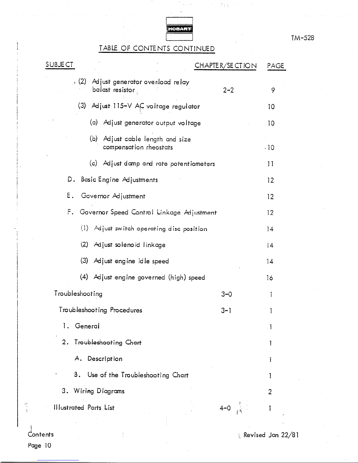
TABLE OF CONTENTS CONTINUED
TM-528
SUBJECT
CHAPTER/SE CT 10 N
I (2) Adjust generator ove?load relay
balast resistor I
(3) Adjust 115-V AC voltage regulator
),
(a) Adiust generator output voltage
(b) Adiust cable length and size
compensation rheostats
(c) Adjust damp and rate potentiometers
D. Basic Engine Adiustrnents
E. Governor Adiustment
F. Covernor Speed Control Linkage Adiustment
(i) Adjust switch operating disc position
2-2
PAGE
9
10
10
El0
11
12
12
12
14
(2) Adjust solenoid linkage
(3) Ad just eng ine id le speed
(4) Adjust engine governed (high) speed
Troubleshooting
Troubleshooting Procedures
1. General
2. Troubleshooting Chart
A. Description
8. Use of the Troubleshooting Chart
3. Wiring Diagrams
II lustrated Parts List
3-o
3-l
4-o ,,ii
14
14
16
1
1
1
1
ontents
c!
Page 10
j, Revised Jan 22/81
Page 15
I 1
TM-528
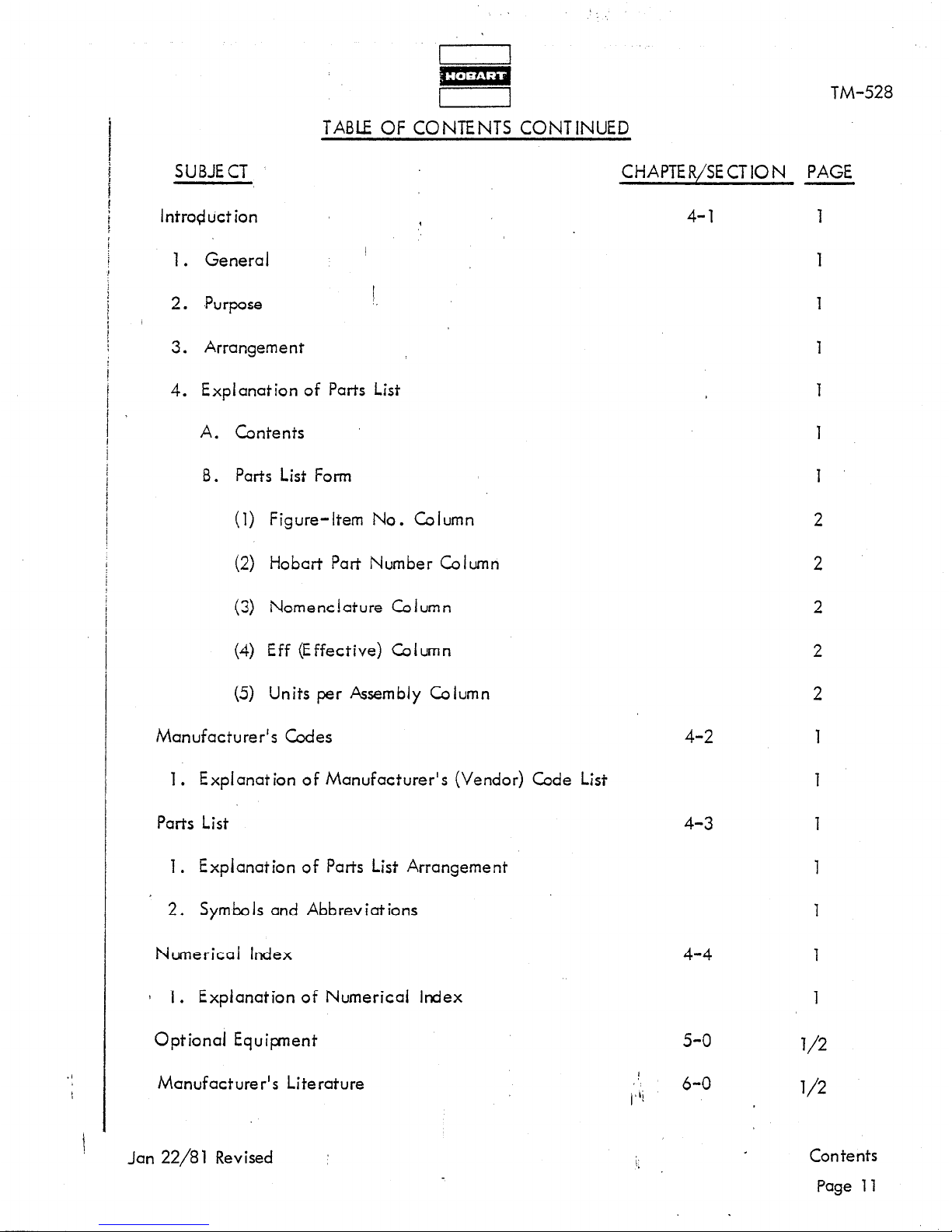
TABLE OF CONTENTS CONTINUED
SUBJECT
Intro#uct ion
1. General
I
2. ,Purpose
3. Arrangement
CHAPTER/SECTION PAGE
1
4-l 1
4. Explanation of Parts List
A. Contents
B. Parts List Form
(1) Figure-Item No. Column
(2) Hobart Part Number Column
(3) Nomenclature Column
(4) Eff (Effective) Column
(5) Units per Assembly Column
Manufacturer’s Codes
1. Explanation of Manufacturer’s (Vendor) Code List
Parts List
1. Explanation of Parts List Arrangement
2. Symbol s and Abbreviations
Numerical Index
1 1. Explanation of Numerical Index
Optional Equipent
Manufacturer’s Literature
Jan 22/81 Revised :
4-2
4-3
1
4-4
1
5-o
1
6-O
Li
1
l/2
l/2
i;
Contents
Page 11
Page 16
I
(’
j CHAPTER/
j SECTION
l-l
l-2
l-2
l-2
l-2 !
l-2
l-2
l-2
l-2,
l-2
l-2
l-2
l-2
l-3
l-4
l-4
l-4
l-4
2-l
2-l
2-l
2-l
2-l
2-l
2-l
2-l
2-2
2-2
2-2
2-2 1
2-2
2-2
2-2
3-l
3-l I
3-1
3-l
3-l
.I
3-l
1 4-3
FIGURE
NUMBER
I
,l
1
2
3
4
5
6
7
8
9
10
11
12
1
1
1
2
3
1
1
2
3
4
5
6
7
1
1
2
3
4
5
6
1
2
3
4
5
6
1
1
‘&
I
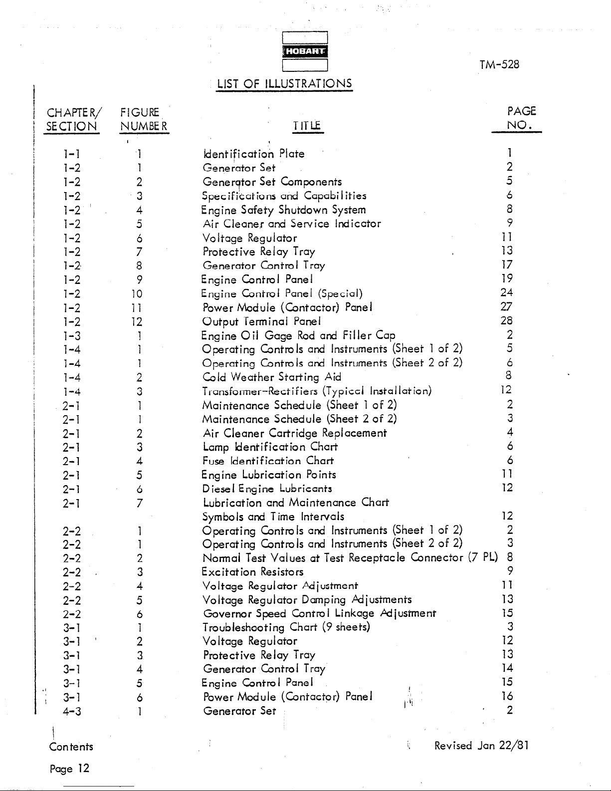
LIST OF ILLUSTRATIONS
TITLE
Identification Plate ’
Generator Set
Generator Set Components
Specifications and Capabilities
Engine Safety Shutdown System
Air Cleane,r and Service Indicator
Voltage Regulator
Protective Relay Tray
Generator Control Tray
Engine Control Panel
Engine Control Panel (Special)
Power Module (Contactor) Panel
Output Terminal Panel
Engine Oil Gage Rod and Filler Cap
Operating Controls and Instruments (Sheet 1 of 2)
Operating Controls and Instruments (Sheet 2 of 2)
Cold Weather Starting Aid
Transformer-Rectifiers (Typiccl Installation)
Maintenance Schedule (Sheet 1 of 2)
Maintenance Schedule (Sheet 2 of 2)
Air Cleaner Cartridge Replacement
Lamp Identification Chart
Fuse Identification Chart
Engine Lubrication Points
Diesel Engine Lubricants
Lubrication end Maintenance Chart
Symbols and T ime Intervals
Operating Controls and Instruments (Sheet 1 of 2)
Operating Controls and Instruments (Sheet 2 of 2)
Normal Test Values at Test Receptacle Connector (7 PL) 8
Excitation Resistors 9
Voltage Regulator Adiustment
Voltage Regulator Damping Adiustments 13
Governor Speed Control Linkage Adiustment
Troubleshooting Chart (9 sheets) 3
Voltage Regulator
Protective Relay Tray 13
Generator Control Tray 14
Engine Control Panel
Power Module (Contactor) Panel
Generator Set
I
/;i
TM-528
11
13
17
19
24
27
28
8
12
11
12
12
11
15
12
15
16
PAGE
NO.
1
2
5
6
8
9
2
5
6
2
3
4
6
6
2
3
2
!
Con tents
Page 12
5
Revised Jan 22/81
Page 17
./
!
CHAPTER/
FIGURE
SECTION
NUMBER
4-3
4-3
4-3
4-3
4-3
4-3
4-3
4-3
4-3
4-3
11
4-3 12
4-3
13
4-3
14
4-3 15
4-3 16
4-3 17
4-3 17A
4-3
18
4-3 19
4-3 20
1
!/r
I,
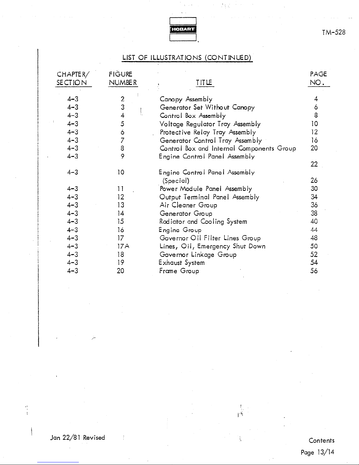
LIST OF ILLUSTRATIONS (CONTINUED)
2 ~
3
4
5
6
7
8
9
10
<’
TITLE
I
.
Canopy Assembly
Generator Set Without Canopy
Control Box Assembly
Voltage Regulator Tray Assembly
, Protective Relay Tray Assembly
Generator Control Tray Assembly
Control Box and Internal Components Group
Engine Control Panel Assembly
Engine Controi Panel Assembly
(Special)
‘Power Module Panel Assembly
Output Terminal Panel Assembly
Air Cleaner Group
Generator Group
Red iator and Coo I ing System
Engine Group
Governor Oil Filter Lines Group
Lines, Oil, Emergency Shut Down
Governor Linkage Group
Exhaust System
Frame Group
TM-528
PAGE
NO.
4
6
8
10
12
16
20
22
26
30
34
36
38
40
44
48
50
52
54
56
r
Jan 22/8 1 Revised :
Contents
Page 13/14
Page 18

Page 19
id
I
i,NTRODUCTiON
This manual contains operation and, maintenance information for a 400-Hz Generator Set
which may be either truck or trail&r mounted,.
Brothers Company,
The purpose of the manual is!to provide operators and maintenance personnel with instructions
and information which will guide and ,assist them in the efficient operation and maintenance
of the ground power equipment.
these instructions and familiarize’ themselves with the characteristi’cs, capabilities, and
limitations of the unit.
The manual is divided into six chapters. Each chapter is d ivided into as many sections as
required .
section begins with Page one and the first illustration in each section is Figure 1.
Should this manual contain additional information required to cover optional equipment,
modifications, changes and updated designs, added after the original manual was released,
this information will be added at the end of a Section where it would normally be found.
Added or changed information is indicated by a solid black line in the left-hand margin
of the page, opposite the new or revised material.
Pages and illustrations are not numbered consecutively through the manual. Each
Power Sjstems Division, Troy, Ohio 45373.
Ail personnel responsible for the equipment should read
1
These units are manufactured by Hobart
TM-528
Always refer to the Table of Contents, or to the last page (s) of a Section to determine
if special information hcs been added for your particular machine.
Refer to Chapter 1, Section 1 for an explanation of how to identify generator sets.
Chapter 5 lists ail options available for use with the basic generator set.
lists ail pertinent,manufacturer’s literature which is furnished with this manual, including
schematic and connection diagrams.
Chapter 6
!
Jan 22/81 Revised
:
I)
Introduction
Page l/2
Page 20

.,
Page 21
TM-523
CHAPTER 1. DESCRiPTlON AND OPERATION
SECTION 1. IDENTIFICATION
I
9
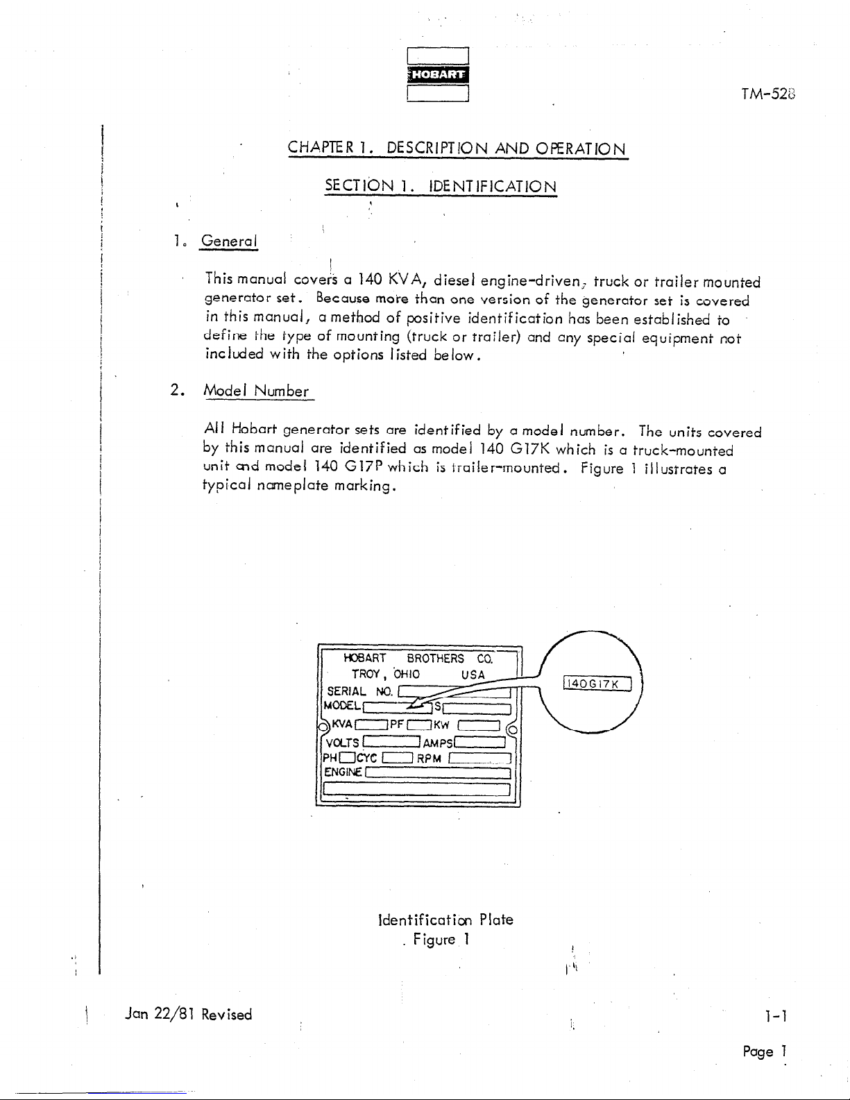
1. General
This manual coveA a 140 KVA, diesel engine-driven; truck or trailer mounted
generator set.
Because more than one version of the generator set is covered
in this manual, a method of positive identification has been established to
define the type of mounting (truck or trailer) and any special equipment not
included with the options I isted below.
2. Model Number
Ail Hobart generator sets are identified by a model number. The units covered
by this manual are identified as model 140 G17K which is a truck-mounted
unit end model 140 G17P which is trailer-mounted. Figure 1 illustrates a
typical nameplate marking.
1 WART BROTHERS CO. 1
If-Y
K’JAOPFOKW
Identification Plate
. Figure 1
\
Jan 22/81 Revised
Page 1
Page 22
TM-528
140G17K defines a generator set mounted on any of the truck options listed below.
140G17P defines a generator set mounted on the optional trailer.
140G17P (special) ‘defines a trailer-mounted generator set which includes special equipment.
3. Optional Eqbi,pment
Optional equipment consists of trucks,
transformer-rectifier mounting kitk, a revolving amber light and a test box.
/
A. Trucks
The truck options consist of Chevrolet model CS-51403, Ford model F-500, GMC
model CS-51403 and Dodge model D-500.
B. Truck Body Kits
Truck body kits, part number 482150, are available for mounting the basic generator
set, with or without transformer-rectifiers, on any of the available truck options. These
kits are described and illustrated in TO-110.
I
C. Trailer
I
The optional trailer, part number 482158,
TO-106.
,
truck body kits, trailer, transformer-rectifiers,
is covered by an instruction manual
D. Transformer-Rectifiers
Transfomler-rectifiers are available to change the 115-V AC generator output to 28.5,
35 and 112 V DC. The 28.5 volt unit is covered in TM-597, the 112 volt unit is covered
in TM-598 and the 35 vo It unit is covered in TM-599.
E. T-R Mounting Kits
Transformer-rectifier mounting kits, part number 482163, are available for mounting
any combination of T-R units on the optional trucks at-d trailer. These kits are covered
in TO-111.
F. Test Box
The optional test box, part number 388318-4, is available to check voltage levels at
critical points throughout the circuitry.
It plugs into the test receptacle connector
on the engine control panel of each unit. This option is covered in TO-112.
Page 2
\;
Revised Jan 22/81
Page 23
I
I
TM-528
G. Revo iving Light (Truck-Mounted Units)
This emergency warning iigbt revolves through 3600. Central iy mounted on top
of the truck cab, it has an ‘on-off switch located on the dashboard. This option
is covered in TO-1 13.
1
Jan 22/81 Revised ;
i.
l-l
Page 3/4
Page 24

Page 25
!d
r I
SECT1 ON 2. DESCRIPTION
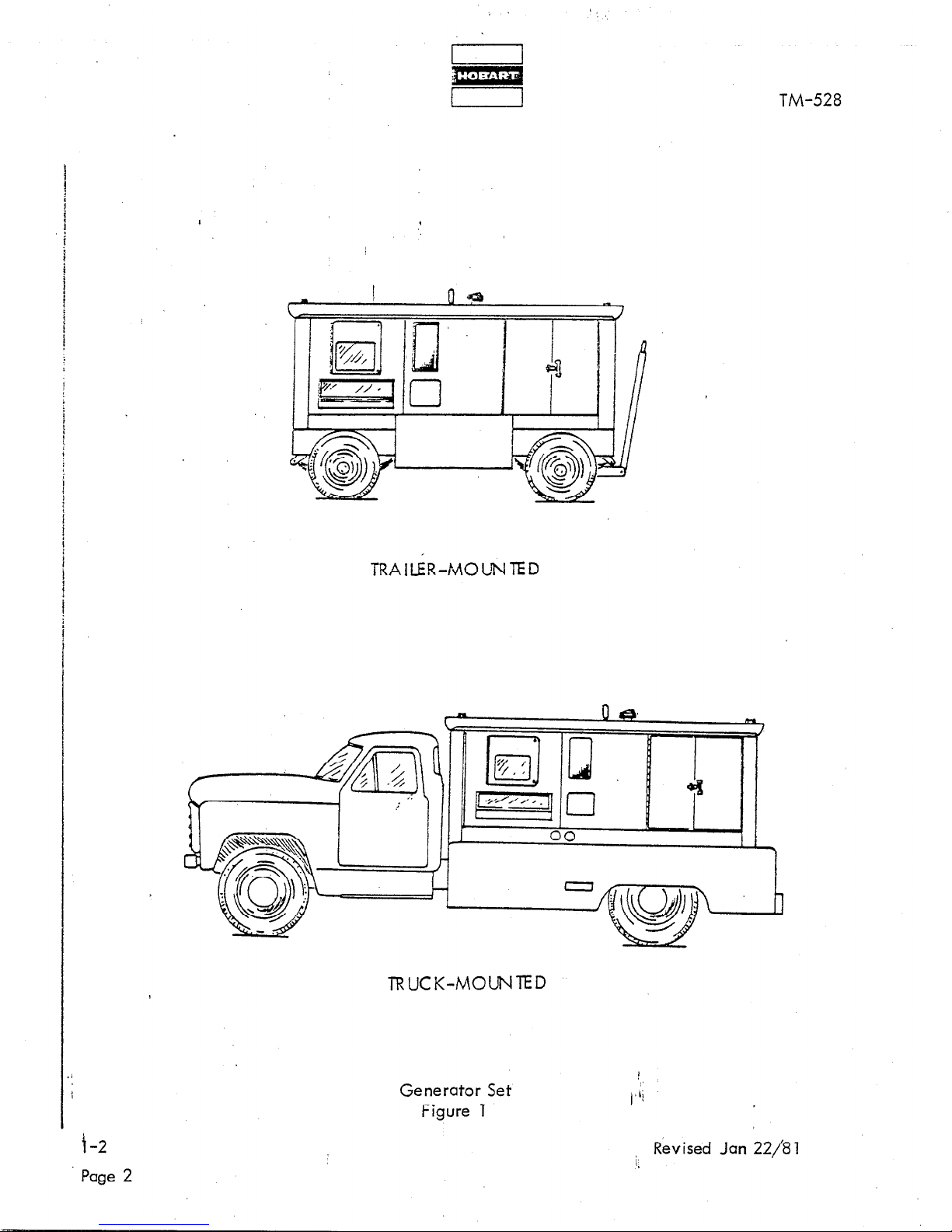
1. General
The generator set covered by this manual is a diesel engine-driven unit,
enclosed by a canopy and designed for mounting on a truck or trailer
(See Fig. 1). ’
TM-528
/
The purpose of the generator set is to produce and deliver regulated, 400-Hz,
115/200-V AC power to one o,r two parked aircraft for operation of the air-
craft’s electrical equipment when the on-board generators are not running.
Orientation
2.
For purposes of orientat ion and to fcm ii iarize operators and maintenance
personnel with the location of components, the radiator is considered to
be at the FRONT of the unit. The generator and controls are at the REAR.
RIGHT and LEFT are determined by standing at the rear and facing the
math ine .
and engine control panel are mounted on the RIGHT side at the REAR of
the unit.
NOTE: When the generator set is mounted on a truck, the rcdictor or
FRONT end of the generator set is at the REAR of the truck.
Operating controls are then on the LEFT, or driver’s side, of
the truck. When the generator set is mounted on a trailer,
the radiator is at the drawbar, FRONT end.
3. Special Features
Thus, the generator control box, output receptacle connector,
The generator has many special features which are described more fully
under the assemblies in which they appear. Some of the main features
are mentioned here and described briefly.
A. Protective Monitor System
A single, solid-state device (1, Fig.
the fault sensing units in the generator output circuit and functions
to cause the load to be disconnected from the generator if an abnormal
condition of voltage,
Pullout Trays
B.
The control box is equipped with pullout, drawer-type trays which
provide easy access to controls and equipment md,unted in them.
Each tray may be removed as an assembly by disbbnnecting a single
quick-disconnect connector and tripping two safety latches.
Jan 22/81 Revised :
7) receives signals from ail of
frequency or load develops.
1,
l-2
Page 1
Page 26
/
I
m
I 1
TM-528
TRAILER-MOLNTED
TRUCK-MOUNTED
Generator Set
Figure 1
f-2
Page 2
i Revised Jan 22/81
Page 27
TM-528
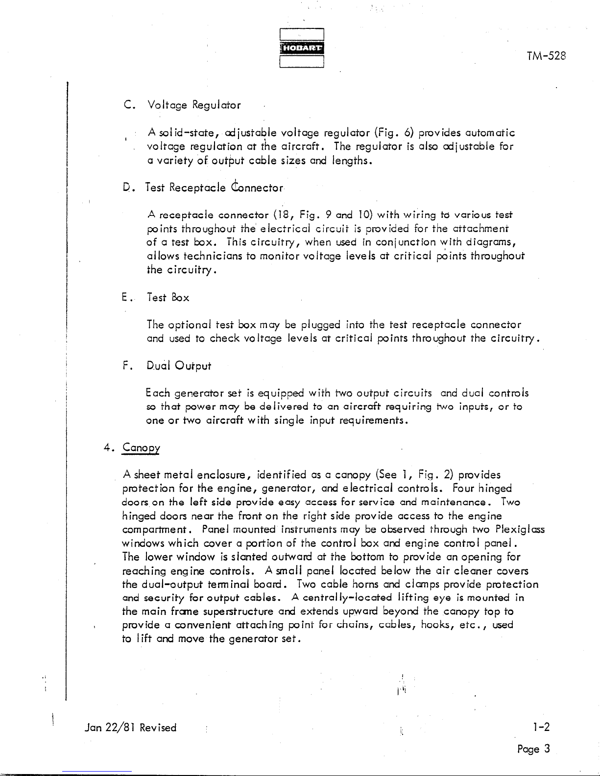
C. Voltage Regulator
I
A solid-state, adiustabie voltage regulator (Fig. 6) provides automatic
voltage regulation at f’he aircraft.
The regulator is also adiustabie for
a variety of output cable sizes and lengths.
D. Test Receptacle Connector
A receptacle connector (18, Fig. 9 and 10) with wiring ta various test
points throughout the eiectricai circuit is provided for the attachment
of a test box. This circuitry, when used in conjunction with diagrams,
allows technicians to monitor voltage levels at critical points throughout
the circuitry.
E.
Test bx
The optional test box may be plugged into the test receptacle connector
and used to check voltage levels at critical points throughout the circuitry.
F.
D.uai Output
Each generator set is equipped with two output circuits and dual controls
so that power may be delivered to an aircraft requiring two inputs, or to
one or two aircraft with single input requirements.
4. Canopy
A sheet metal enclosure,
identified as a canopy (See 1, Fig. 2) provides
protection for the engine, generator, and electrical controls. Four hinged
doors on the left side provide easy access for service and maintenance. Two
hinged doors near the front on the right side provide access to the engine
corn partme nt .
Panel mounted instruments may be observed through two Plexiglass
windows which cover a portion of the control box and engine control panel.
The lower window is slanted outward at the bottom to provide an opening for
reaching engine controls.
A small panel located below the air cleaner covers
the dual-output terminal board.
Two cable horns and clamps provide protection
and security for output cables.
A central iy-located lifting eye is mounted in
the main frcrne superstructure and extends upward beyond the canopy top to
provide a convenient attaching point for chains, cables, hooks, etc., used
to I ift and move the generator set.
Jan 22/81 Revised
:
i;
l-2
Page 3
Page 28
m
I 1
TM-528
L
I
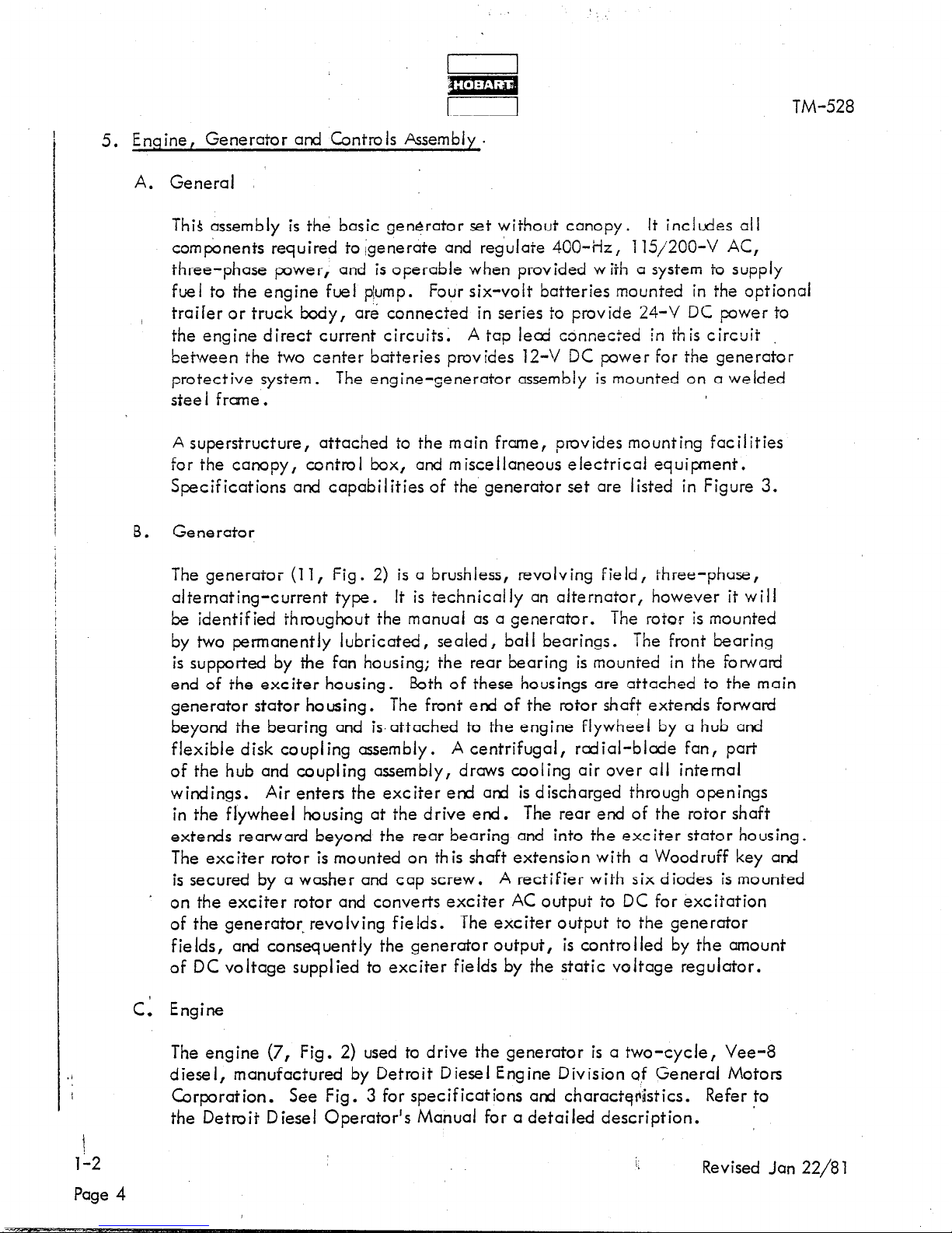
5. Engine, Generator and Controls Assembly.
A. General
This assembly is the basic generator set without canopy.
It includes all
components required to igenerate and reg’ulate 400-iiz, 115/200-V AC,
three-phase power,
and is operable when provided with a system to supply
fuel to the engine fuel plump.
Four six-volt batteries mounted in the optional
/
trailer or truck body, are connected in series to provide 24-V DC power to
the engine direct current circuits:
A tcp lecd connected In this circuit
between the two center batteries provides 12-V DC power for the generator
protective system.
The engine-generator assembly is mounted on a welded
stee I f rme .
A superstructure,
attached to the main frame, provides mounting facilities
for the canopy, control box,
and m isceiianeous electrical equipment.
Specifications and capabilities of the’generator set are listed in Figure 3.
8.
Gene rato r
The generator (11, Fig. 2) is a brushless, revolving field, three-phase,
alternating-current type.
It is technically an alternator, however it will
be identified throughout the manual as a generator. The rotor is mounted
by two permanently lubricated, sealed, bail bearings. The front bearing
is supported by the fan housing; the rear bearing is mounted in the forward
end of the exciter housing.
Both of these housings are attached to the main
generator stator housing.
The front end of the rotor shaft extends forward
beyond the bearing and is. attached to the engine flywheel by a hub and
flexible disk coupling assembly.
A centrifugal, radial-blade fan, part
of the hub and coupling assembly, draws cooling air over ail internal
windings.
Air enters the exciter end and is discharged through openings
in the flywheel housing at the drive end. The rear end of the rotor shaft
extends rearward beyond the rear bearing and into the exciter stator housing.
The exciter rotor is mounted on this shaft extension with a Woodruff key and
is secured by a washer and cap screw.
A rectifier with six diodes is mounted
on the exciter rotor and converts exciter AC output to DC for excitation
of the generator revolving fields.
The exciter output to the generator
fields, and consequently the generator output, is controlled by the amount
of DC voltage supplied to exciter fields by the static voltage regulator.
C. Engine
The engine (7, Fig. 2) used to drive the generator is a two-cycle, Vee-8
diesel, manufactured by Detroit Diesel Engine Division af General Motors
Corporation. See Fig.
3 for specifications and characterh’stics. Refer to
the Detroit Diesel Operator’s Manual for a detailed description. ’
112
Revised Jan 22/81
Page 4
Page 29
f
n Ili=l n I 1
i i
I 1
u
r 1
TM-528
/
II
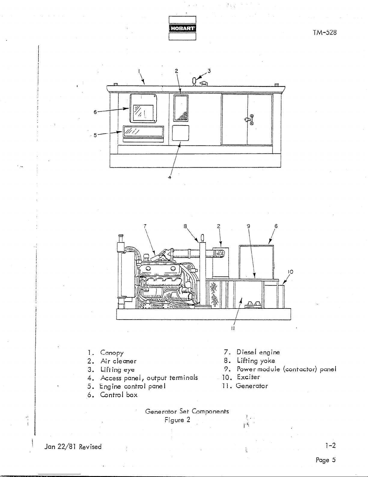
1. Canopy 7. Diesel engine
2. Air cleaner 8. Lifting yoke
3. Lifting eye
9. Power module (contactor) panei
4. Access panel, output terminals 10. Exciter
5. Engine control panel 11. Generator
6. Control box
Generator Set Components
Figure 2
1
.
(‘Ii
!
Jan 22/8 1 Revised
l-2
Page 5
Page 30

GENERATOR
I I
TM-528
Output power rating
0 utput voltage
Rated lo&I capacity
Overload capacity (125% of lrated load) ’
Frequency (cycles-per-second)
0 utput ki iowatts
Po,wer factor
Duty cycle
Operating speed (at 400 Hz)
Output cable size (each of four conductors)
ENGINE
Manufacturer
,
I
,.
Detroit Diesel Engine Div.
140 KVA
115/200-v
404-A
505-A
400 Hz
172 KW
0.8 PF
100%
T7P4 RPM
210
General Motors Corp.
Type
Model
Displacement
Bore and stroke
Governed speed
Horsepower at 1714 RPM
Id!e speed
Overspeed governor trip
Coolant system capacity (approx.)
Lubricating oil capacity (without filters change) (approx.) 23 quarts (21 liters)
Lubricating oil capacity (with filters change) (approx.) 26 quarts (25 liters)
567 cubic inches (9291 c.m3)
4-l/2 x 5 inches (115 mmx 127 mm)
1900 to 2025 RPM
19-l/2 gals. (74 liters)
8V-77 N diesel
7083-7000
1714 RPM
253 HP
800 to 850 RPM
D. Governor
The mechanical-hydraulic governor (4, Fig. 4) is identified as a Woodward
Model PSG. Instructions and an ii iustrated parts list for the governor are
included in Woodward Bulletin which is supplied with this manual in Chapter 6.
Engine Safety Shutdown System
E.’
(1) General
The automatic, electric, shutdown system is designed to stop t& engine if there is a loss of oil
pressure, overheating of engine coolant, or engine overspeed.
Page 6
Specifications and Capabilities
Figure 3
Page 31

TM-528
(8) Air shutoff valve
The principal component in the safety shutdown system is the air shutoff valve. The valve
consists of a circular, hinged plate which is mounted in the engine air inlet housing (2). The
valve is mounted on a cross-shaft (5) which is spring-loaded in a direction to close the valve.
’ (9) Engine Safety devices :’ ’
General
All fault sensing devi es have a common characteristic. They are basically normally-closed
hydraulic valves. Th 8 ,y also perform a common function: they release oil pressure to the
/
shutdown valve bellows when an engine operating fault occurs. As stated above, this pressure
release allows the bellows assehbly to unlatch and thus close the shutdown valve. Sensing
devices are series-connected in the oil supply line to the bellows assembly so that the operation
of any device will release pressure to the bellows. Fault sensing devices are described in detail
in the Detroit Diesel Operators Manual.
a. Overspeed governor
The overspeed governor is a mechanical fly-weight type, mounted at the rear of the engine
and driven through an adapter by the camshaft. Electrical contacts in the governor are
connected in parallel with other engine shutdown devices. The governor is adjusted to close
the contacts and actuate the shutdown solenoid when an engine speed of 1950 RPM is
reached. The governor must be manually reset, after tripping, by pushing a button located on
the governor head.
b. Temperature sensing safety switch
This switch is mounted in the engine water manifold and is identified as an “Alarmstat”. It
is very sensitive to temperature changes and functions to protect the engine against
overheating caused by low coolant level, broken fan belt, etc. It sends a signal which
activates the shut-down solenoid to stop the engine when temperature in the cooling system
reaches 205 deg. F.
c. Start circuit cut-out switch
This is a Micro-type switch, mounted just below the air-valve operating lever. The switch
is electrically connected in series with the starter switch. In normal operation the switch is
CLOSED. In the event the shutdown solenoid is actuated to stop the engine, the shutdown
switch is OPENED to prevent operation of the engine starter until the shutdown air valve is
LATCHED in OPEN position.
cf. Start circuit solenoid switch
This switch is mounted on a bracket on the left side of the engine below the time delay
relay. This soleniod type switch functions to conduct 24-V DC power to the engine starter
solenoid when the panel mounted pushbutton start switch is pushed. The soleniod switch
serves to by-pass and protect the start circuit cut-out switch against the heavy load current of
the starter.
e. Low oil pressure switch.
This switch is mounted on the engine block. It sends a signal to the time delay relay when
engine oil pressure drops below 10 psi. The time delay relay serves to delay for
approximately 10 seconds the activation of the shutdown solenoid.
!
March 24/95 Revised
1-2
Page 7
Page 32

LEFT SIDE OF ENGINE
TM-528
RIGHT SIDE OF SHUTDOWN VALVE
1.
Bellows assembly
2. Shutoff valve housing
3.
Overspeed
4.
Engine
5.
1 Valve shaft
governor
governor
./
1-b
Page 8
6. Shutdown valve operating solenoid
7. Low coolant and high temperature
valve
8. Emergency shutdown solenoid valve
Engine Safety Shutdown System
Figure 4.
t
‘I
(#hi
i Revised Jan 22/8 1
Page 33

F.
Air Cleaner
I
I
TM-528
The diesel-engine air cleaner (Fig. 5) is a dry-cartridge type.
It is equipped
with a moisture eiiminator and a service indicator. The indicator functions
to ‘signal the operator when the cartridge needs changing. A red cylindrical
flag (2) is forced upward in a glass enclosed viewing chamber (7) when air
I
pressure within the air:!cleaner housing drops below the outside air pressure.
As the cartridge becomes loaded with dirt and air pressure within the cleaner
lessens, the flag gradually rises higher in the glass viewing chamber. When
the flag reaches the top of the chamber,
it locks in that position to warn the
operator that the cartridge must be changed.
The flag is reset (unlocked) by
pushing the reset button (3) located on the bottom of the indicator.
G. Control box
The control box (6, Fig. 2)
is a sheet metal enclosure which houses and provides
mounting facilities for generator controls and electrical equipment. The box
is equipped with three drawer-type trays which contain generator output control
devices and monitoring instruments.
Trays slide in ard out on nylon rollers for
easy access to internally mounted components. Each tray is easily removcble
by disconnecting an amphenol connector, unlocking the safety latches, and
sliding the complete tray assembly out of the control box.
F /- .
1. Viewing chamber
2. Indicating flag
3. Reset button
1
(‘Ii
Jan 22/8 1 Revised
Air Cleaner and Service lnd icator
I
Figure 5
!,
1-2
Page 9
Page 34

TM-528
Two shielded instrument panel iights’are mounted on the left side of the control box
front panel to iliwninate controls and instruments in the trays.
(1) Voltage regulator tray
I
1
1
!
,
,
i
1
1
I
!
The voltage regulator! tray is the topmost in the control box.
regulator manual is supplied with the generator set, a brief, working description
is given here.
The voltage regulator is designed to provide 1% voltcge regulation with 0.25second recovery time for a,ll loads up to 100% of rated load on a three-phase,
fo ur-w ire,
field excitation power for the rotary exciter,
voltage by varying the exciter field power as required to meet varying load
conditions. Thus, the generator output is held at a constant voltage. The
maximum continuous rating of this regulator is 4.0 Amperes at 140 Volts DC.
Any deviation of the generator output voltage from its set, regulated level
is sensed by the voltcge detection and comparison circuits.
from the comparison circuit into the transistorized pre-amp1 ifier, cmpl ified,
and used to drive the magnetic cmplifier. The magnetic unpiifier output
changes in response to this signal,
exciter enough to return the generator voltage to its regulated value. The
voltage at which the generator is regulated may be odiusted w
adjustment rheostat (2, Fig. 6).
115/200-Volt, 400-Hz, brushless generator. This regulator provides
I
and regulates generator output
chcnging the field power of the rotary
Although a separate
A signal is fed
,ith the vo I tage
i-2
(a) Contro is
The rheostat (2, Fig. 6)
of the generator output.
potentiometer (4).
another potentiometer (3).
OFF by a toggle switch (5).
be ON. An instruction plate under the potentiometer knobs indicates
pmper setting for various cable sizes and lengths. Regulator stability
is adjusted by the damping circuit gain potentiometer (8). Regulator
response time is adiusted by the damping circuit rate potentiometer (10).
(b) Protection
Internal circuitry of the voltage regulator is protected by a cartridge
type, 5 Ampere fuse (12).
(c) Components
See Fig. 6. Refer to Operation and Maintenance”Manual No. T*M-759 for
a detailed description of the voltage regulator.
is used to adjust the regulated voltage value
Compensation for cable size is adiusted by a
Cable length is compensated for by adiustment of
Cable compensation may be turned ON or
For this application the switch must always
1
Revised Jan 22/8 1
Page 10
Page 35

m
1
1
TM-528
i
1. Resistor (1000 Ohms, 25 Watts)
2. Regulator rheostat
3.
Cable length compensation rheostat
4.
Cable size compensation rheostat
5.
On-Off switch, line drop compensation
6. Line drop compensation, chassis assembly
7.
Receptacle connector
8.
Damping circuit gain potentiometer
9. Receptacle connector
0.
Damping circuit rate potentiometer
11. Receptacle connector
12. Fuse (5A)
13. Fuseholder
14. Receptacle connector
15. Sensing and preamplifier chassis
assembly
16. High-phase sensing board assembly
17. Reactor
18, Chassis
19. Terminal board
Voltage Regulator
Figure 6
1
( ,‘ii
Jan 22/81 Revised
:
l-2
1,
Page 11
Page 36

(2) Protective relay tray
TM-528
Refer to Fig. 7.
The center tray in the control box is identified as the protective
relay tray and contains electrical and electronic safety devices designed to pro-
‘tect the aircraft electrical systems against damcge which could result from over-
voltage, undervo ltqge, or underfrequency.
The tray also contains devices for
the protection and control of the generator output electrical system. The Generator Schematic Diagram shows how the protective devices are located in the
electrical system. ”
(a) Sensing relays
The overvoltage relay (3), undervoltage reiay (4), underfrequency relay
(5), and over-frequency relay (6)
are connected to the generator output
lecds between the generator and the load contactor. These relays sense
any abnormal condition of voltage or frequency and signal the soiid-state
circuitry of the protective monitor module (I) to open the load contactor
holding circuit and disconnect the generator output to the aircraft.
Solid-state overload signaling devices (one for each output) are also
connected to the protective monitor module and perform a function
similar to the sensing relays.
/
t
‘1-2
Page 12
Trip values for the sensing relays and overload devices are as follows:
Overvoltage relay trips at 130 V to 134 V.
UndeNoltage relay trips at 93 V to 103 V.
Overfrequency relay trips at 415 Hz to 425 Hz.’
Underfrequency relay trips at 375 Hz to 385 Hz.
Overload device trips at any value over 125% rated load capacity.
(b) Protective monitor module
The protective monitor (1) is a solid-state device with a hermetically-
sealed, reed-type, relay.
The solid-state, printed circuit board or card
replaces five latching relays and a time delay relay which were formerly
used. SCIRs (
si icone-controlled rectifiers) are used, one each for over-
I
frequency, underfrequency, overvoltage, under-voltage, and overlood.
The board includes five memory circuits and an odiustable time delay
circuit.
device (overload module, overvoltage relay, etc.).
Each memory circuit is connected to a corresponding sensing
All of the circuits
are connected to the module relay coil, and any one of the circuits can
energize the coil to open the relay contacts. Thus, when a sensing
device energizes any one of the module circuits,, the module relay is
also energized to break the load contactor hoI@g circuit and allow
the load contactor to open.
All circuits, except the undervoitage
circuit, function immediately to open the load contactor.
Revised Jan 22/8 1
Page 37

TM-528
1.
Protective monitor module
2. Fuse interlock relay
3.
Overvo I tage sensing relay
4.
Under-voltage sensing relay
) 5. Underfrequency sensing relay
6. Over-frequency sensing relay
7; Generator overload relay
8.
Tray fastener
( 9. Overlood indicating I ight
10.
Reset SW itch
11. Undervoltage indicating light
12.
No. 1 resistor, 100 Ohm, 25 Watt
13.
Overvoltage indicating light
14. No. 2 resistor, 100 Ohm,
25
Watt
15. Under-frequency indicating light
16. interlock relay fuse, 2A
17. Underfrequency indicating light
18. Load contactor circuit fuse, 2A
19. Test bank switch
20. Capacitor, 6.8 MFD, 35 V
21. Terminal board
22. Diode, 400 V RV, 1.5 A
.’
23. Receptacle connector
24. No. 1 plug-interlock relay
25. No. 2 plug-interlock relay
Protective Relay Tray
Jan 22/81 Revised
Figure 7
l-2
Page 13
Page 38

TM-528
A time delay system is designed into the under-voltage circuit to prevent nuisance
opening of the contactor under conditions of momentary under-voltage in the
generator output.
An undervoltage condition which continues uninterrupted
for a period of 4,to 12 seconds will cause the time delay circuit to open the
load contactor. Each of the five circuits is connected to a corresponding
indicating light (9.,, T 1, 13, 15,
and 17) wh ich is turned on when a fault
occurs.
I
)_
The module relay will remain energized (OFEN) and the light will remain ON
until the reset switch (10) ,is pushed to break the module 12-V DC circuit, and
allow the relay to return to normal, CLOSED position.
(c) Indicating I ights
The function of these lights (9, 11, 13, 15 and 17) is to indicate, to the
operator, the abnormal condition of overvoltage, underfrequency, etc.,
which caused the protective monitor system to function. Each of the five
lights is connected to an actuating circuit within the memory and time delay
module. When one of the circuits is activated, it turns on th,e applicable
ind icating light.
The light will remain on until the reset switch (10) is
pushed. These are press-to-test type lights in which the lamps (bulbs) may
be tested by pressing the lens holder momentarily.
(d) Plug interlock relay
The function of the plug interlock relay (24) is to cause the No. 1 output
load contactor to open in the event the cable plug connector becomes
accidentally disconnected from the aircraft during power delivery, or
if an attempt is made to deliver power when the output cable is not
connected to the aircraft.
Twenty-eight Volt direct current for operation
of the relay is supplied from the aircraft either through an on-board
transformer-rectifier, or from a twenty-eight Volt electrical system.
Connection from the aircraft to the interlock relay is made through
terminals E and F on the cable connectors. Another relay (25) functions
in the scme manner for No. 2 output load contactor.
(e) Test-bank SW itch
A sp st, toggle switch (19) provides a means of bypassing the interlock
relays (24 and 25) h
w en supplying power to a load bank or to aircraft
not equipped with a plug interlock system.
In the TEST BANK position
the interlock relays are bypassed. In AIRCRAFT position, they are
switched back into the circuit.
t
T-2
i* Revised Jan 22/8 1
Page 14
Page 39

TM-528
(f) Resistor
I
A 100 Ohm, ,25 Watt resistor (12) is connected in series with the plug
interlock relay (24) to ptotect the relay in the event that phase C contacts
in the No. 1 load contactor should fail to close when the generator ON
switch is pushed. An identica’l resistor (14) perfons the same function
for No. 2 relay (24).
/
(g) Fuse interlock relay
I
I
I
The function of the fuse interlock relay (2) is to interrupt the locd contactor
holding coil circuit and remove the load in case of a bldwn fuse (16) in the
protective relay coil circuit.
(h) Connector
A twenty-six contact connector, (23) provides a quick-disconnect facility
for all wiring to the trays electrical components so that the complete tray
assembly may be removed quickly and easily.
(i) Diode, capacitor and terminal board
A terminal board (21)
is used to mount and connect a diode (22) and
capacitor (20) into the fuse-interlock relay coil circuit. Their purpose
is to prevent an inductive spike in the 12-V DC circuit from triggering
an SCR in the protective monitor module (1) and turning on an indicating
light when no fault exists.
(k) Overload relay
This overload relay (7) is a thermal type with manual reset.
its function
is to protect the generator in case both output circuits are operated to
capacity at the same time.
The relay signals the protective monitor
module to open both loach contactors in approximately 5 minutes when
the generator is operated at 125% to 127% rated load .
(I) Fuses
A fuse (18) is located in the load contactor hold circuit to protect the
power module in case of a rectifier failure. Another fuse (16) protects
the 12-V DC protective monitor circuit.
Jan 22/81 Revised :
T-2
Page 15
Page 40

1
j
,
I
i
t
i
I
,
i
,
!
f
I
!
/
(3)
./
t
l-2
Page 16
.
Generator control tray
The generator control tray (Fig. 8) is the bottom tray in the
contains ‘instruments and controls for monitoring at-id control
output.
4
TM-528
control box. It
ling 5
(a) Res iston
’
Two 25 Ohm,
TOO !Watt, ballast resistors (1) are connected
the generator DC field circuit.
:nerator
n series in
A 50 Ohm, 100 Watt variable resistor (12) is connected in series between
the manual control rectifier (15) and rheostat (14). Its purpose is to adiust
the DC voltage to the rheostat.
This odiustment determines the generator
output voltage control range of the rheostat e
(b) Generator output meters
The generator output is monitored by three instruments; a frequency meter
(8), a voltmeter (7), and an cmmeter (6). The frequency meter is a
resonant-reed type, and indicates the frequency of the generator output
alternating current in the range of 380 to 420 Hz (cycles per second).
The voltmeter indicates the generator output voitage in each phase-to-
neutral (A-N, B-N and C-N)
or phase-to-phase (A-B, B-C and C-A)
as selected by the meter selector switch (5) and the line selector switch
(4). (These switches are described below .) The voltmeter has a 3-1/2inch (89 mm) face and the scale is graduated 0 to 300 V. The ammeter
is also 3-l/2-inch size and is graduated 0 to 500 Ai The crnperage value
in each of the three phases may be read on the cmmeter by selecting the
desired phase with switch (5). Th
ree ammeter current transformers (4,
Fig. 11) lower the output load current to a lesser value, of definite
ratio, which will operate the ammeter movement without damage. The
ammeter dial scale is grcduated and numbered so that the pointer will
indicate the true load current value rather than the meter movement current.
(c) Meter and line switches
These switches provide a means of selecting and determining which phase
of voltage and current is indicated on the voltmeter and ammeter and
whether the voltage is line-to-neutral or line-to-line. The meter switch
(5) is a four-position, rotary type. A nameplate (3), located under the,
switch knob, is marked and lettered to indicate the three functional
positions of the meter switch.
(When the knob is pointing straight down,
the switch is OFF.) The line switch (4) is a two-posi!tion, toggle switch
used to select either line-to-neutral or line-to-line (@Itage to the voltmeter.
The nameplate is also marked to indicate the position of this
SW itch.
i,
Revised Jan 22/81
Page 41

I
1
1.
2.
3.
4.
5.
6.
7.
8.
m
I
1
8
7
TM-528
Resistor (25 Ohm, 100 Watt)
Fastener
Instruction plate
Line selector toggle switch
Meter selector rotary switch
AC Ammeter
Voltmeter :
Frequency meter
TO.
11.
1-2.
13.
14.
15.
Generator Control Tray
Figure 8
Nylon roller
Receptacle connector
Tray
Resistor (50 Ohm, 100 Watt)
Automatic-manual switch
Manual voltage control rheostat
Rectifier
), Ii
Jan 22/81 Revised
1
l-2
Page 17
Page 42

TM-528
(d) Receptacle connector
An Amphenol connector (10) provides a means of quickly disconnecting
all wires to generator control tray components.
(h)’ Tray
,
I
The tray (11) slides in and out on nylon rollers (9). It
is secured in place
I
by two captive screw fasteners (2).
(f) Manual voltage control
When the automatic manual switch (13)
Is placed n MANUAL position,
AC power is supplied to the rectifier (75) rather than to the automatic
voltage regulator.
The DC output of the rectifier is routed to the exciter
fie Id through a rheostat (14).
The generator output voltage is thereby
manually controlled by adiustment of the rheostat.
H. Engine and Generator Control Panel (140Gl7K and 14OGl7P)
Refer to Fig. 9.
The engine and generator control panel assembly is mounted
directly below the generctor control box.
lnstrwnents and controls are protected
by a clear Plexiglass panel which is mounted in a frune that extends outward
and downward at an angle over the contra I panel.
Instruments may be observed
through the Plexiglass panel and controls may be operated by reaching under
the pane I.
(1) Engine gages and meters
(a) 0 il pressure gage and diaphragm switch
The oil pressure gage (7)
is a bourdon tube type and indicates engine
I ubricat ing oil pressure.
It is graduated from 0 to 75 psi (0 to 517 kPa).
Adiaphragm type switch (8) is mounted in the oil line directly behind
the oil gage. Th
is switch is closed by engine oil pressure and connects
24-V DC to the hourmeter, throttle holding solenoid, and-excitation-
deenergization relay only when the engine is running.
(b) Ammeter
The ammeter (6) indicates the d irection and the value of the current
flow in the engine 24-V DC electrical system. Its graduated range
is from -30 Amperes through 0, to +30 Amperes.
\
l-2
[I Revised Jan 22/8 1
Page 18
Page 43

, ,
:‘.
_
a:
I
TM-528
1. Excitation-deenergization relay
2. Panel light
3. Push-to-build-up-voltage switch
4. Fuse, lights and excitation circuit (IOA)
5. Light switch
6. Ammeter, DC circuit
,7. Oil pressure gage
8. Diaphram switch, hourmeter and
excitation circuit
9. Coolant temperature gage
10. Hourmeter
1’1. Speed control switch
12.
DELETED
13. Engine speed control cable
14.
Start switch
15.
DELETED
16.
Terminal board
17. Engine running indicating light
18. Test receptacle connector
19.
No. 2 contactor
indicating
light
20.
No. 1 contactor
indicating
light
21.
No. 1 contactor
operating
switch
22.
No. 1 contactor
operating
switch
Engine Control Panel (140G17K and 140G17P)
Figure 9
1
Ii
March 24/95 Revised
1-2
Page 19
Page 44

I
m
r
(c) Temperature gage
The temperature gage (9) is of one piece construction ard consists
8
of a panel mounted indicating mechanism which is connected to an
engine-mounted bulb by a capil’lary tube. The gage indicates
engine coolant temperature ‘in a range of 1000 F to 220’ F ( 38O C
to m” C).. 1
(d) Houneter
The hourmeter (70) is electrically driven from the 24-V battery
system. The hourmeter measures and records elapsed runhing
time when the engine is operating.
actual operating time which is required for meeting maintenance
schedules.
NOTE: The houneter used on 140G17P (Special) is a 12-V DC unit.
,.
Its function is to record
TM-528
Panel lights
(2)
Two shielded instrument panel lights (2) provide illumination for
instruments and controls during night-time operation.
(3) Indicating lights
There are three indicating lights mounted on the control panel.
(a) Engine ON indicating light
This light (77) gl ows green when the engine is running and
engine lubricating oil pressure is holding the diaphragm switch
(8) closed.
(b) Load contactor indicating I ights
Each output load contactor holding coil circuit has an indicating
light (19 and 20) h’ h I w IC g ows red when the circuit is energized
and is holding the contactor closed. When the lood contactor
opens for any reason,
the I ight is turned OFF.
NOTE: Fault indicating lights in the protective relay tray are
described in Para. 5, G, (2), (c).
t
l-2
Page 20
1
(‘Ii
eevised Jan 22/81
Page 45

TM-528
(4) Switches
a. Starter switch
This is a pushbutton switch (14, Fig. 9) which connects a 24-V DC power signal to the starter
solenoid. The solenoid then engages the starter and supplies power for cranking the engine.
I
b. Speed control switch -1
This is a single-throw, on-off toggle switch (11) used to connect DC power to a solenoid in the
governor speed control linkage. When the switch is ON, the solenoid functions to hold the
linkage in governed speed position for normal generator operation. This toggle switch also
connects power tothe excitation-deenergization relay circuit.
c. Light switch
Panel lights (2) and clearance lights are controlled by another single-throw toggle switch (5).
d. Load contactor control switches
Each load contactor is controlled by a toggle switch. No. 1 output contactor is controlled by
switch (21). No. 2 output contactor is controlled by switch (22). These are three-position
switches which are spring-loaded in the top “ON” position. When placed in the spring-loaded
ON position, the switch provides 115-V AC power directly to a rectifier which supplies DC
power for closing the load contactor. When released, it returns to the normal ON position and
continues to provide power to the rectifier. But in this switch positionAC power must pass
through the plug interlock and fuse interlock relays. In OFF position, the switch opens the AC
circuit to the rectifier, thereby cutting off the source of DC power to the contactor coil abd
allows the contactor to open.
March 24/95 Revised
1-2
Page 21
Page 46

I
r:
I
(e) Push-to-build-up-voltage switch
TM-528
This is a pushbutton switch (3) that connects initial power to the excitation-
deenergization relay (1) at generator startup.
It is functional only if the
speed control switch (11)
is ON and the engine is operating at governed
,
speed..
(5) Excitation-deenergization relay
’ This relay (1) is mounted on the back of the engine control panel. Its function
is to connect AC power to the voltage regulator so that the regulator may supply
excitation to the exciter fields.
The relay is only functional when the engine
is running at governed speed,
and the engine speed control switch (11) is in 0 N
position.
(6) Fuse
A 10-A fuse (4) protects the 24-V DC, light and engine-generator speed control
circuit.
(7) Test receptacle connector
This Amphenol connector (18) provides an attaching point for leads which are
connected to selected test points throughout the
engine and generator electrical
systems.
Connection and schematic diagrams indicate points at which the lecds
are connected.
This receptacle connector is designed to mate with a test box
plug connector.
It is protected by a dust cap.
The test box, part number 388318-4,
is available from Hobart Brothers Company at a nom inal kharge. Refer to 2-2;
Para. 2. B. (29) for a description of its use.
(8) Speed control cable
This push-pull control cable (13)
is connected to the engine governor linkage
and is used to position the linkage for the engine speed desired. It is also used
for normal engine shutdown.
A hinged latch, mounted on the panel behind the
1 control cable knob, holds the control out sufficiently for normal idle speed when
the latch is held in UP position,
the control is allowed to move to its ful I IN
position which allows governor linkage and fuel racks to go to NO-FUEL position
and stop the engine.
. l’-2
Page 22
;,Rev ised Jan 22/8 1
Page 47

.
‘.
ti
m
L
I
TM-528
(10) Terminal boar+&
,.
Three terminal boards (16)
are mounted on the back of the control panel
near the lower ed’ge.
They provide convenient connection terminals for
wires leading to and from control panel components.
J.
Special Engine and Generator Controf Panel (140G17P Special)
(1) General (See Fig. 10)
Only those items are described here which are added to the standanf control
panel. Note that some standard items are located differently. item numbers
‘I through 22 on Fig.
10 identify the same parts that’they did in Fig. 9. New
items 23 through 31 have been added at the end of the list 0
(2) Receptacle connector ard circuit breaker
A twist-lock type receptacle connector (29) provides a convenient outlet
connection for a light or small hand tool requiring 115-V, 400-Hz power.
This output circuit is protected by a 20-A circuit breaker (23).
(3) Emergency-stop switch
A single-throw,
toggle switch (24)
connects power to a solenoid valve in
the engine safety shutdown system.
When activated the valve releases
pressure in the engine air valve latching system and causes the air valve
to close and stop the engine.
(4) Hourmeter diaphragm switch
Another diaphragm switch (25) is added behind the oil pressure gage to
connect 12-V DC to the hourmeter (lo), only when the engine is running.
This circuit is protected by a 2-A fuse (28).
(5) Load contactor switches operating handle
A special handle (30)
is mounted on the load, contactor switches to operate
both switches simultaneously., If both outpuplicable plugs are not’connected
to an aircraft, only the contactor in the circuit being used wi,ll remain
closed .
Jan 22/81- Revised ’
l-2
Page. 23,
Page 48

TM-528
16
26 30 19
16 I8
1. Excitation-deenergization relay
2. Panel light
3. Push-to-build-up-voltage switch
4. Fuse, lights and excitation circuit (1 OA)
5. Light switch
6. Ammeter, DC circuit
7. Oil pressure gage
8. Diaphram switch, hourmeter and
excitation circuit
9. Coolant temperature gage
10. Hourmeter
11. Speed control switch
12. DELETED
13. Engine speed control cable
14. Start switch
15. DELETED
16. Terminal board
17. Engine running indicating light
18. Test receptacle connector
i7
28
19. No. 2 contactor indicating light
20. No. 1 contactor indicating light
21. No. 1 contactor operating switch
22. No. 1 contactor operating switch
23. Circuit breaker, convenience output
circuit
24. Emergency stop switch
25. Hourmeter operating diaphragm
switch
26. Low fuel (engine stopped) warning
light (red
27. Push switch, low fuel system test
28. Fuse, fuel warning system test
29. Convenience output receptacle
(115-V, 400-Hz
30. Load contactor switches
operating handle
31. Fuel warning system relay
Engine Control Panel (140G17P Special)
;!I
Figure 10
(,I1
‘9
Pzige 24
March 24/95 Revised
j>
Page 49

I 1
(6) Low fuel warning and shutdown system
This system warns the operator when engine fuel is low and also automatically
stops the engine before the tank is completely empty.
Two sensing devices (not shown) are mounted in the fuel tank. The uppermost
device sends’a signal to q relay (31) w h en fuel in the tank reaches a low
level which will allow only cpproximateiy 30 minutes of operation.
relay (37) fu&ions to turn on a flashing,
mounted on the canopy top. If the tank is not filled when the warning light
comes on, the lower sensing device will activate the emergency shutdown
solenoid to stop the engine before the tank is emptied. A red warning
light (26) indicates to the operator that the engine has been stopped due
to low fuel (if blue flashing light is also on), or an emergency. The fuel
warning system is protected by a 2-A fuse (28). A push switch (27) is
used for testing the flashing light circuit.
After a low-fuel shutdown, fuel must be odded in tank to turn off warning
I ights.
rotating warning light which is
TM-528
The
K. Power Module
The power module, or contactor pane I (Fig.
position above the generator below the control box.
power module panel assembly are identified as follows:
(1) Capacitor
The function of the three capacitors (l), which are connected to the
generator output leads at the bus bar (3) terminals, is to eliminate radio
frequency interference before it is transmitted along the 400-Hz output
cables.
(2) Line-drop current transformer
The three line-+rop current transformers (2), in conjunction with the
burden resistors (8), detect the magnitude and power factor of current
flowing from the generator to the load, and feed a signal to the voltage
regulator which interprets the signal and alters the exciter field current
as required to maintain a constant predetermined voltage at the load.
(See Voltage Regulator Manual TM-759) ,,
11) is mounted in a horizontal
Components of the
(3) Ammeter current transformer
The three ammeter current transformers (4) low&r the output load current
to a lesser value of definite ratio which will ‘$erate the ammeter movement without damage .,
so that t.he ammeter pointer w iii ind icate the true load current value
rather than the meter movement current..
Jan 22/81 Revised
The ammeter dial scale is graduated,and numbered
1,
l-2
Page 25
Page 50

Page 51

.
‘4
1
TM-528
SECTION 3. PREPARATION FOR USE
1.
Generator Set
A., General
,
The generator s&t is shipped i’n operating condition and is ready for use
after inspection dnd check.
CAUTION: READ ORRAi-lNG INSTRUCTIONS IN’ CHAPTER 1,
SECTION 4, BEFORE OPERATING THE UNIT.
B.
Inspect ion/Check
Inspect at-xi check the generator set thoroughly before operating.
(1) Remove crating, blocking, banding, ties, and other securing
and protective material.
(2) Inspect exterior for shipping damage such as broken’glass, dcmaged
sheet metal, etc.
(3) Open all canopy doors and inspect interior for foreign material
such as rags, tools, shipping papers, etc.
(4) Check fuel, coolant, and oil hoses and connections for visible
leaks. Check the ground surface under the unit for evidence
of leaks. If leaks are discovered, correct by tightening hose
clamps, tube fittings, etc., as required.
(5) Check security of attaching and retaining hardware.
(6) Check f II
0 owing for sufficient quantity.
(a) Diesel fuel tank capacity is as follows:
Trailer -
approximately 65 gallons (246 liters).
Truck
- approximately 89 gallons (337 I iters).
(b) Engine coolant level should be approximately one inch
(25 mm) below the fillerneck to allow a sufficient
capacity for coolant expansion.
CAUTION: BE SURE THE COOLING SYSTEM ANTIFREEZE
SOLUTION ,IS ADEQUATE v-F0 PROTECT BELOW
LOWEST TEMPERATURE EXPECTED.
Jan 22/81 Revised :
l-3
Page 1
Page 52

I I
m
1
TM-528
/
(c) The oil’gage rod (Fig.
See 2-1, Fig.
6, or Detroit Diesel Operator’s Manual for oil recommendations.
1) has F (ful I) and L (low) level marks to indicate
lubricating oil level in the oil pan.
Oil level should be kept as near
tlhe F mark as possible.
$:
I
CAUTION: NEVER OFERATE THE ENGINE WITH OIL LEVEL BELOW THE
LOW-E/‘/EL MARK OR ABOVE FULL-LEVEL MARK.
(7) The air cleaner (Sect. 1-2, Fig. 5) is a dry type. Be sure there are no papers,
tapes, or other materials covering the air inlet area.
(8) Check fluid I
evel in the four 6-Volt batteries.
Fluid should cover plates.
!
RIGHT BANK
1. Oil level gage rod
2. Oil filler cap
I
Engine Oil Gage Rod and Filler Cap
Figure 1
I
l,-3
Page 2
:Revised Jan 22/81
‘,
Page 53

I I
.w
I
TM-528
1
C. Output Cables Installation
I
!
I
(1) Cable requiremepts
2
8
Cable leigth is determined by the customer’s requirements, however,
t
it is recom r ended
that cables be no longer than 40 feet (12 meters).
[
,,
1
li
A five-conductor cable assembly with four, size 2/O conductors
and one No. 1,2 conductor is recommended for each output. The
cable should be equipped with an AN-3430 plug connector on one
end and ring-type terminals on the other.
(2) Cable connection
(a) Remove output terminal panel access cover (l-2; 4, Fig. 2) on
the right side of the generator set near the control box.
(b) Loosen cable horn clamps and insert the loose ends of ccble
assemblies through cable horns. Route to output terminal panel.
(c) Each terminal is identified by a letter, A, B, etc., indicating
the generator output phase.
Cable lecds are likewise identified
by ident if icat ion bands. Connect one cable assembly to the
upper Tow of terminals. Connect the other to the lower row.
Connect A iecd to A terminal, B lead to B terminal, etc.
Connect small No. 12 lead to either E ‘or F terminal. Tighten
all connections securely.
I
(d) When connections have been made, tighten cable clamps at
cable horns, and install access panel.
(e) On truck mounted unit 140G17K, remove wooden blocks from
cable plug boxes on the left side of the truck and insert cable
plugs.
!
Jan 22/8 1 Revised
:
l-3
Page 3/4
Page 54

Page 55

‘:
1
SEC-ilON 4. OFERATION
1. General
Information on operation of the optional trucks and trailer is included
he;e.for the convenience of tee operator. For detailed coverage of
these options,
see the Qppropriate truck manufacturer’s manual or
TO-106 for the trailer.
I
I
,,
I
NOTE: Read ALL of the operctiqg instructions before attempting to
operate the unit.
WARNING: EAR PROTECTiON MAY BE NECESSARY WHEN WORKING
IN CLOSE PROXIMITY TO THIS EQUIPMENT.
’
2.
Operating the Truck
A. General Operating Instructions
(1
) Operators should familiarize themselves with the truck controls
and responses before attempting to position the vehicle for
servicing an aircraft.
A little practice in a clear area may
help to prevent a future accident.
TM-528
(2) Read the Truck Owner’s Manual.
(3) Position the side mirrors to give the best possible view to the
rear on both sides of the truck.
(4) Observe and note all blind-spots.
(5) Visually inspect and mentally mste the location of al I controls.
(6) After making certain of an assured clear operating area, drive
the truck to become familiar with starting, stopping, and turning
characterist its.
(7) Never reverse the truck without assurance of a clear area to the
rear.
WARNING: AVOID SUDDEN STARTS OR STOPS EXCEPT IN
CASE OF EMERGENCY. AVOID SUDDEN TURNS..
B.
Starting the Truck Engine
On 140G17K, a safety feature has been cdded to t& truck ignitiqn
system to prevent engine starting if output cable plug connectors are
not properly stored in plug boxes.
If the engine fails ,to start, check
cable plug b&es first.
1,
Jan 22/81 Revised
1-4
Page 1
Page 56

C. Positioning the Truck
1
TM-528
Position the truck to the aircraft in accordance with airline directives.
This procedure will depend upon airport regulation, type of aircraft, etc.
When truck is properly positioned:
(I) Apply parking brake. I ”
’
(2) Place transmission in NFUTRAL and release clutch.
,.
‘(3) Stop engine.
3. Operating the Trailer
A: General
(1) Be sure the brakes are released before attempting to tow the trailer.
(2) Always apply brakes when the unit is parked.
8. Operating the Brakes
Pull the brake lever forward and inward to apply brakes. The brake lever
operates on an over-center locking principle. Brake application pressure
applied to brake shoes is adjustable by a threaded krob located on top
of the brake lever handle.
Turning the knob CLOCKWISE increases
brake pressure and causes an increase in the effort required to apply
the brake and pull the handle into automatically locked position.
The brake lever handle points directly, forward when in locked position.
The brake is released by pushing the lever inward toward frame.
C. Drawbar
When the trailer is not connected to a tow vehicle, the drawbar should
always be locked in a stowed,
upright position in the support assembly.
The drawbar is locked in the support automatically when lifted to an
upright position.
To release, push inward on the drawbar, lift the latch,
then lower the drawbar.
4. Operating the Generator Set
A. ‘General
The sequence of events in preparation for power delivery is not critical
to the point that cables should be plugged into the aircraft before starting
the diesel engine, etc.,
however, time may be saved if the diesel engine
is started and warmed before the vehicle (truck or trailer) I!$ positioned at
11-4
the aircraft.
Revised Jan 22/8 1
.Page 2
Page 57

/
czi
m
i
TM-528
8. Connecting Output Cables
Generator sets covered by this manual are designed to supply power to a
single aircraft having a split-bus electrical system which requires two
1
inputs, or fo one or two single system aircraft.
(1) Remove cable(s) from cable storage box. Remove plug connectors from
plug boxes if the unit is so equipped.
,.
(2) Gnnect cable plug tonnector(s) to aircraft receptacle(s) as required
by type of aircraft.
Make certain that the plug and receptacle
connectors are fully and securely mated. if difficulty is experienced
in making the connection,
inspect pin-type terminaas in the plug
connector for damage.
C. Preparation for Power Delivery
It is good practice to make a quick check of all generator controls before
start-up to make certain they are correctly positioned and have not been
tampered with.
After all controls have been checked at the beginning
of an operational shift, it is not necessary to repat the checks for each
aircraft servicing throughout the shift if it is known POSITIVELY that
controls have NOT been tampered with.
Check the position of generator
contra Is as fol lows: (See F’g
I ure 1 which illustrates all generator and
engine contra Is .)
(1) Voltage regulator tray
(a) The .line-drop-compensation toggle switch (33) must be in ON
position.
(b) Do not disturb the regulator rheostat (37) adjustment unless
the generator is operating and it is necessary to adjust the
output voltage.
(c) Do not disturb other adiustments. They are set at the factory.
(2) Protective relay tray
(a) The test bank switch (42)
must be in AIRCRAFT position for
delivery of power to an aircraft equipped with an interlock
contra I system .
(b) Make certain the overload relay (43) is in ON position.
Jan 22/8 1 Revised
1-4
Page 3
Page 58

czil
m
L
(3) Generator control tray
(a) Be sure automatic-manual toggle switch (48) is in AUTOMATIC
position.
I
TM-528
e meter selector’switch (49)
Th ’ (b)
(pointing straight down),
/
(c) The line seieLtor switch (50) should be in LINE-TO-NEUTRAL
psition.
(4) Engine and generator control panel
Check position of controls as follows:
(a) Circuit breaker (23) ON
(b) Emergency stop switch (24) OFF
(c) Speed control switch (11) OFF
(d) Light switch (5) as required.
(e) Locd contactor switches (21 and 22) OFF
NOTE: The engine starting toggle switch (14) is spring locded so
that it is normally OFF unless held in ON position.
may be in any position except OFF
I
l-4
Page 4
D. Normal Engine Starting
Engine starting steps are outlined below.
illustrated in Fig. 1.
CAUTION: REFER TO OPERATING INSTRUCTIONS IN THE DETROIT DIESEL
~FERATORIS MANUAL, WHEN STPRTING ENGINE FOR THE
FIRST TIME.
(1) If illumination or clearance
ON position.
(2) Pull speed control (13) OUT about half-way and be certain hinged stop
(behind knob) is DOWN.
lights cre required, place light switch (5) in
(3) Press and hold starter switch (14) to crank engine.
Engine controls ad instruments are
!,
(‘Ii
/
Revised Jan 22/81
. .
Page 59

.
TM-528
1. Excitation-deenergization relay
2. Panel light
3. Push-to-build-up-voltage switch
4. Fuse, lights and excitation circuit (10A)
5. Light switch
6. Ammeter, DC circuit
7. Oil pressure gage
8. Diaphram switch, hourmeter and
excitation circuit
9. Coolant temperature gage
10. Hourmeter
11. Speed control switch
12. DELETED
19. Engine speed control cable
14. Start switch
1.5. DELETED
16. Terminal board
17. Engine running indicating light
18. Test receptacle connector
19. No. 2 contactor indicating light
20. No. 1 contactor indicating light
16 28
:4
13
21~ No. 1 contactor operating switch
22. No. 1 contactor operating switch
23. Circuit breaker, convenience output
circuit
24. Emergency stop switch
25. Hourmeter operating diaphragm
switch
26. Low fuel (engine stopped) warning
light (red
27. Push switch, low fuel system test
28. Fuse, fuel warning system test
29. Convenience output receptacle
(115-V, 400-Hz
30. Load contactor switches
operating handle
31. Fuel warning system relay
NOTE:
140G17P (Special) control panel is
illustrated because it includes all
standard controls as well as special
items.
Operating Controls and Instruments (Sheet,!! of 2)
March 24/95 Revised
I
Figure 1
(,I!
1-4
Page 5
Page 60

32 .
33 .
34 .
35 .
36 .
37 *
Rate and gain adjustments
Line drop compensation switch
Cable size, compensation ad-l
justment
Cable length compensation I
adi ustment
Instruction plate
Voltage adjusting rheostat
38 .
39 a
40 .
41 *
42 .
43 .
Fault indicating light (5)
Load contactor operating system fuse
Protective monitor system fuse
Protective monitor system reset switch
Test bank switch
Generator overload relay
PROTECTIVE RELAY TRAY
44.
Frequency meter
45 .
AC voltmeter
46 .
Manual control rheostat
47 .
AC Ammeter
48.
Automatic-manual switch
49 .
Meter switch
50 .
Line SW itch
Gperating Controls and Instruments (Sheet 2 of 2),$
Figure 1
t
i-4
Page 6
I 1
m
I
1
TM-528
VOLTAGE REGULATGR’TRAY
38
39
40
1,
Revised Jan 22/81
Page 61

(4) When the engine starts,
.
.
iiiia
i--1
release the starter switch button (14),
TM-528
.-
I
I
! ’
, (5) Use speed control (13) to cdiust engine speed to a fast idle (1000
to 1200 RPM).
I
9
DO NOT’OFERATE A COLD ENGINE AT FULL-SFEED.
CAUT’ON’ ’ i
I
(6) Observe all engine instruments for normal operation.
(7) Allow engine to idle and warm before applying locd.
IF THE,ENGINE FAILS TO START WITHIN 30 SECONDS,
2.’
RELEASE THE START SWITCH AND ALLOW THE START-
ING MOTOR TO COOL FOR A FEW MINUTES.
ENGINE FAILS TO START AFTER FOUR ATTEMPTS, AN
INSPECTION SHOULD BE MADE TO ‘DETERMINE THE
CAUSE.
IF THE EN,GINE FIRES SUFFICIENTLY TO DISENGAGE
3.
THE STARTER GEAR, BUT DOES NOT START, RELEASE
THE START SWITCH AND ALiOW THE STARTING MOTOR
TO COME TO A COMPLETE STOP BEFORE ATTEMPTING
TO ENGAGE THE STARTER AGAIN.
IF THE
CAUTION: DO NOT ALLOW THE ENGINE TO IDLE FOR LONG
PERIODS OF TIME.
Jan 22/81 Revised
:
l-4
Page 7
Page 62

.
. .
I
1
TM-528
(4) Pull speed control (13, Fig. 1) OUT about half-way.
(5) Hold starting switch (15)
in UP,, spring-loaded ON position and press starter
switch (14) to crank, engine.
+ the engine is being cranked, PULL the pump
plunger (12) all the way OUT,‘.then pushsIN slowly to force starting fluid
through the atomizing nozzle into the air intake housing. Continue to push
the plunger IN slowly until engine starts.
(6) When the engine starts,
release starter switch button (14). Hold starting
togale switch in ON position, until the green engine light (17) comes ON - -
then RELEASE.
(7) Adiust speed control (13) for fast idle.
NOTE: If the pump plunger is not all the way IN when the engine starts,
push it in slowly to LOCKED’position.
F’JMP
INLET
NEE
./
t
Cold Weather Starti,ng Aid
( .‘li
Figure 2
i
/
l-4
Page 8
0
Revised Jan 22/8 1
Page 63

TM-528
F. Power Delivery (Automatic Voltage Control)
After the unit has been prepared for power delivery (Para. 4, C), and the
engine has been started and warmed,
400-Hz power may be delivered to the
aircraft .
(1) Connect generator output cable(s) to aircraft as required, if they are not
al ready connected as instructed in Para. 4, B above.
(2) Place speed control switch in ON position.
(3) Pull speed control (13) OUT to full speed Position.
(4) Press push-to-build-up-voltage switch (3). Check voltage reading on
voltmeter (45).
Should be 115-V AC line-to-neutral.
(5) To apply power to the aircraft,
close load contactor switches (21 and 22)
as required.
Hold switch in top, ON position until corresponding green
indicating light comes ON. Release switch. It will return to center ON
or contactor closed position.
On 140Gl7P (Special), use the switch handle (30) to operate cantactor
switch. Although.both contactors will be closed momentarily, only
the contactor in the circuit which is plugged into the aircraft will
remain closed.
(6) It is recommended that the operator check output voltage and current
in the three phases early in the power delivery run. Use the meter
switch (49) to select the phase.
Use the toggle SW itch (50) to select
line-to-line or line-to-neutral voltage. If the load is changing, it
is good operating practice to observe the instruments until load co.n-
ditions stabilize.
It is also good practice to check the engine gages
and instruments regularly for normal readings.
,
1
Jan 22/81 Revised
l-4
\>
Page 9
Page 64

G. Power Delivery (Manual VoltageControl)
Power delivery using manual means for controlling the generator output voltage
is basicail,y an emergency operation and should be used only in case of voltage
regulator failure, or when the unit is being tested. To operate using manual
control, follow the standard operating procedures as instructed above with the
following exceptions: I
Place the automatic/-manual switch (48) in MANUAL position.
(1)
(2) Regulate the generator output voltage by controlling the exciter voltage and
current with the field rheostat (46). Turn the rheostat knob clockwise to
increase output voltage and counterclockwise to decrease voltage.
NOTE: The operator must remain with the unit to adiust the field rheostat
for varying load conditions.
H. Stop Power Delivery
(1) Place load contactor switch(es) (21 and/or 22) in OFF position. Indicating
light(s) (19 and/or 20) should go OFF ind icating that load ‘contacton are
open and load is disconnected from generator set.
TM-528
Place speed control switch (11) in OFF position.
(2)
(3) Push speed control (13) IN to full IDLE position against idle stop.
(4) Disconnect output cables from aircraft. Stow cables in cable box. If
the unit is so equipped,
insert cable plug connectors in plug boxes.
WARNING: NEVER DISCONNECT AN OUTPUT CABLE WHILE POWER
IS ON.
J. Stop Engine
(1) Pull speed control (13) OUT slightly.
Lift hinged control stop and push speed control IN to F
(2)
Emergency Stop (140Gl7P Special)
K.
’
Place emergency stop switch (24) in ON position.
‘UE L-OFF position.
CAUTION: DO NOT USE EMERGENCY STOP SWITCH FOR NORMAL ENGINE
STOPPING.
1
(pIi
NOTE: Be sure stop switch is OFF before attempting to restart engine.’
-4
f
Page 10
i Revised Jan 22/81
Page 65

TM-528
1’
m
5.
Operating Instructions for Optional T-Rs
A. Transformer-Rectifier Operation
Transformer-Rectifier operating instructions are contained in their
I
respective manuals; hawever,
same operating instructions are required
here.
I
(1) Direct current power delivery
NOTE: If the customer adds a Transformer-Rectifier to a standard
machine which was NOT equipped with a T-R when it
left the factory,
he must remove the jumper lecd which
will be found on the small terminal strip in the generator
set voltage regulator {see l-2; 19, Fig. 6). If your
generator set has a factory installed T-R, the jumper will
have been removed.
(a) When delivering power from a SINGLE T-R (28.5-V, 35-V,
or 112-V DC), prepare the generator set for DC power delivery
the scme cs for AC delivery, except do not connect AC output
cable end do not close AC locd contactor (see Para. 4, F).
(b) For T-R operating instructions:
See TM-597 for 28.5-V DC T-R Operating Instructions
See TM-599 for 35-V DC T-R Operating Instructions
See TM-598 for 112-V DC T-R Operating Instructions
(2) Simultaneous 28.5-V at-d 35-V DC power delivery
28.5-V and 35-V DC T-Rs may be operated at the same time
without special precautions.
Prepare the generator set for power
delivery in accordance with Para. 5,A, (I), (a) above. Operate
each T-R according to Instructions in applicable TM.
NOTE: It is NORMAL for T-R output to become SLIGHTLY
unstable (indicated by blinking contactor light on
either T-R) when operating with current I im iting .
When output is unstable, observe DC voltmeter.
Fluctuation of one or two volts is normal. If fluctuation
is violent (several volts), adjust voltage regulator
RATE potentiometer (see 2-2; 2, Fig. 5) to correct.
Jan 22/81 Revised
1-4
Page 11
Page 66

I I
TM-528
(3) Simultaneous 28.5-V DC and 115-V AC power delivery
If both 28.5-V DC and 115-V AC must be delivered at the some time, the foilowing
rules and precautions must be observed.
(a) Place T-R current limiting iwitch in OFF position. This will elim’inate the
soft start feature of the T-R, but will prevent AC voltage from dropping low
enough to trip the AC load contdctor.
(b) Line-drop compensation on the T-R must be REDUCED or turned DOWN
completely to prevent opening of the AC load contactor by an overvoitage
condition.
Readjust T-Rlline-drop compensation so that AC voltage (as
ind icated by the generator set voltmeter) does not exceed 118-V AC when
the DC locd is 500 Amperes.
If higher DC voltage is needed; adiust T-R
line-drop compensation as required. Observe AC voltage while making
this adiustment to be certain that it does not go TOO HIGH with DC load.
(c) During simultaneous, continuous operation, loads on either circuit are
limited only by the capacities of their respective circuits, however, the
combined loads should not exceed the rated capacity of the generator set.
(4) Simultaneous 35-V DC or 112-V DC and 115-V AC power delivery
-
Since neither of these T-Rs have line-drop compensation capability, no special
cdiustment to the T-R will be required. Combined loads should not exceed the
rated capacity of the generator set.
35 m 112-v DC
Trarsfarrzr-Rect if ier
- 28.5-V DC
TransfonnerRectif ier
144
Page 12
Transformer-Rectifiers (Typical lnstai l&on)
.
Figure 3
Revised Jan 22/8 1
I.
Page 67

I
m
1
CHAPTER 2. SERVICING
TM-528
SECTION 1.. MAINTENANCE
1.
General
I
,
To make certain the generator set is always ready for operation, it must be
inspected and maintained regularly and systematically so that defects may
be discovered and corrd,cted before they result in serious damage or failure
of the equipment.
WARNING: STOP OPERATION IMMEDIATELY IF A SERIOUS OR POSSiBLY
DANGEROUS FAULT IS DISCOVERED.
2.
Maintenance Schedule
A. General
A periodic inspection and maintenance’ schedule should be established
and maintained. A suggested schedule is provided in Figure 1, however,
it may be modified as required to meet varying operating ‘and environmental
coed it ions.
3.
Maintenance Schedule Check Sheet
It is recommended that the operator use a maintenance schedule check
sheet. The check sheet will provide a record and serve as a guide for
establishment of a schedule to meet any maintenance requirements.
C. Time Intervals
The schedule is based on both hours of operation and calendar intervals.
These two intervals are not necessarily the same. For example, in
normal operation a lubrication period, based on hours of operation,
will be reached long before the calendar period. The calendar period
is included to make certain that services are performed regularly when
the equipment is stored, or is being operated infrequently. Lubricating
oil standing in engines that are stored, or used very little, may tend to
oxidize and may require changing although it is not dirty. Perform all
services on a whichever comes first basis.
’ D.
Identification of Interval Periods
Each interval period is identified by a letter, A, 6, C, etc., (see Figs.
1 and 7). For example, services under C schedulb should be performed
at the end of each 200 hours of operation, or every’ithree months if the
equipment is operated less than 200 hours in the three months peri,od.
AR services are performed on an As REQUIRED basis.
2-1
Jan 22/8 1 Revised
Page I
Page 68

I
w
I
1
TM-528
HOURLY INTERVAL
8 106 200
500
1000
As
CALENDAR IN,TERVAL
Req. Daily --- 3 MO. 6 MO. Yearly
SYMBOL AR 1 A
B C
D E
I
I
ENGINE
I
Replace air cleaner cartridge
“X
Check crankcase oil level
‘X
Check coolant level
x
Drain fue I filters
X
Check air cleaner indicator
X
Change engine oil
X*
Change oil filter elements
X*
Lubricate engine accessories
X
Change fue I filter elements
X
Check drive be Its
X
Inspect cooling system hoses,
fiftings, etc.
X
Lubricate speed ccntrol and
air valve linkage
1
X
Drain and refill cooling system a
TWICE ANNUALLY
Inspect exhaust system
X
Drain water and sediment from
fuel tank
X
Clean fuel system
X
Clean engine exterior
X
Clean air box drains
X
Clean crankcase ventilating
system
X
Clean blower screen
X
* Refer to Para. 6, D, (4).
Refer to Detroit Diesel Operator’s Manual for engine lubrication and maintenance
procedures.
ELECTRICAL
24-V DC SYSTEM
Check all lights
X
Check charging rate
x
Check wiring and ccnnecfions
x !
Clean electrical connections
x ,,;;
LA . L -- c-I---I..I, ICI-.,& 1 ,c 3\
Mamrertance 3cneuu1c: ~~r~er:i I VI L,
1 -1
Page 2
Figure 1
Revised .Jan 22/81
Page 69

f-i
m
I 1
HOUi LY IN TERVAL
CALENDAR INTERVAL
1
SYMBdL ~1
I
400 HZ SYSTEM
I
Check o&put cables and plug
connecfors
Check’voitmeter
Check ammeter
Check frequency meter
Check all lights
Check protective relays
Check safety switches
Inspct all wiring and
connections
Clean and inspect generally
As
Req.
AR
L
8
Daily
A
X
X
X
X
X
100
200 [ 500
--I
3Mo. 6Mo.
B
=I=
C D
X
X
TM-528
Yeurly
E
Maintenance Schedule (Sheet 2 of 2)
Figure 1
A definite time schedule for changing the air filter cartridge (element)
cannot be determined because of varying operating conditions. Change
the cartridge as required. (See ‘Para. 3, below .)
3. Air Cleaner Cartridge Replacement
The filter cartridge requires replacement when the indicator flag (Sect. 1-2;
item 2, .Fig. 5) becomes locked in top (full view) position. Proceed as follows:
A. Removal
(1) Loosen the four wing nuts (1, Fig. 2), unlatch clamps (3), and swing
the tee bolts (4) outward away from the moisture eliminator (7).
(2) Remove the moisture eliminator (7).
(3) Remove the filter cartridge (6) and discard.
CAUTION: DO NOT CLEAN OR RE-USE.
(4) Inspect the interior of the cleaner’ho
sing (5). Make certain it is
free of all foreign material.
Yt
Jcn 22/81 Revised
2-l
Page 3
Page 70

I
m
a
TM-S28
8. Installation
(1) Carefully insert the new cartridge into the housing. Avoid hitting the cartridge
tubes against the housing sealing flange.
Make certain the cartridge is seated
properly within the housing,.
Press all edges and corners of the cartridge firmiy
with the fingers to effect a’positive air seal against the sealing flange of the
housing.
I
C.AUTlON: UNDER NO CIRCUMSTANCES SHOULD THE CARTRIDGE
BE POUNDED OR.STRUCK IN THE CENTER TO EFFECT
ASEAL. ._
(2) Lock the cartridge in place by installing the moisture eliminator (7) and
clamping in place with the four tee bolts, clamps and wing nuts.
(3) Wing nuts must be tightened evenly, crisscrossing from corner to corner.
After tightening the nuts as tight as possible by hand, tighten them two
full turns with a small wrench.
1. Wing nut 5. Housing
2. Spring washer 6. Cartridge
3. Clcmp 7. Moisture eliminator
4. Tee bolt.
Air Cleaner Cartridge Replacement
tl
figure 2
Ii
b-l
Page 4
Revised Jan 22/81
Page 71

NOTE: Check the wing nuts three or four days later and retighten if required.
4. Electrical System (24-V and 12-V DC)
A. 1 Lights
,
Check all lights for proper operation DAILY. Replace any defective lamps
(bulbs) as soon as di
I”
covered.
Figure 3 lists ALL lamps, their location, and
part numbers.
”
B. Fuses
Check and replace fuses as required. See Figure 4 for fuse sizes and
locations. Figure 4 includes all fuses used in both the engine and generator
electrical systems.
C. Wiring and Connections
(1)
Inspect all cables and leads for broken, worn, and dunaged insulation.
(2) Check electrical connections for looseness.
NOTE: A darkened term inal generally indicates a loose connection.
D. Battery Service
(1) General
Four &volt batteries are connected in series to supply 24-V power
for cranking the engine and for operating lights, engine shutdown
safety system,
etc. 12-V DC is topped from the circuit for operation
of the 400-Hz generator protective sy&em, and the hourmeter on
140Gl7P (Special).
(2) Battery location and accessibility
On trailer-mounted units, batteries are mounted in a box on the
left side of the trailer.
Two hinged covers provide access to
batteries for inspection and service. On truck-mounted units,
batteries are located in the truck body on the left (drivers) side.
Two hinged covers prov ide access.
(3) Battery care
(a) When a battery has been removed, never aoow it to rest on
concrete, ground,
or metal unless proper nsulation is provided. f !
A wooden platform or board will provide sufficient insulation.
Jan 22/81 Revised
;
1.
2-l
Page 5
Page 72

I I
TM-528
Light
Identification
1
lnstrumen t Pane I
Lights
E’ngine ,ON Indieating Light Panel
1
Contactor CLOSED’ Engine Control
’ Indicating Light Panel
Fault indicating Protective Re lay
Light Tray
Clearance Lights
Control Box and
Engine Ccntrol
Panel 1
Engine Control
Canopy Lamp Industry 313
Locatik Manufacturer
Lamp
,
’ Lamp Industry
Trade No.
Lamp Industry
Trade No.
Lamp Industry
Trade No.
Lamp Indusky
Trade No.
Trade No.
Lamp lden tification Chart
Figure 3
_ _ . __
Lamp -(bulb)
Number
66
313
I 120 MB
1815
_
Sect. l-2; Fig. 7,
Sect.
Fuse Identification Chart
Figure 4
l-2; Fig. 10,
1
.-
;!
1
Page 6
Revised Jan 22/81
t
Page 73

I
m
1
I
TM-528
(b) Maintain stored batteries in a charged condition.
(c) Be sure batteries are fastened securely in the vehicle to avoid damage
from vibration.
1
(d) Maintain battery fluid at proper level.
(e) Keep battery terminal posts and lead connectors clean.
WARNING: (a) BATTERIES GIVE OFF HIGHLY FLAMMABLE
GAS. NEVER ALLOW SPARKS OR OPEN FL&E
NEAR THE BATTERIES.
(b) AVOID SPILLING ELECTROLYTE ON HANDS OR
CLOTHING.
(4) Liquid level
The fluid in each cell should be above the plates at all times. When the
fluid is below this level, add pure distilled water. Never use hydrant
water or any water which has been in a metal container. Acid or electro-
lyte should never be odded except by a skilled batteryman.
CAUTION: NEVER ADD ANY SPECIAL BATTERY DOPES, SOLUTIONS,
OR POWDERS.
NOTE: It is especially important to keep the battery at full charge for
cold weather operation.
Add d isti I led water to the battery in
freezing temperatures only when the engine is to operate for
several hours to thoroughly mix the water and the electrolyte,
ordunage to the battery may result from freezing.
(5) Cleaning the battery
If the top of the battery is dirty, it may be cleaned with a brush dipped in
ammonia or soda solution. The vent plugs must be tightened to prevent any
solution from getting into the battery cells. After the foaming stops, flush
off the battery with clean water.
Brighten term inal and post surfaces with
steel wool, a wire brush, or special terminal cleaning tool. Make certain
that the vent holes in filler caps are not clogged.
CAUTION: DO NOT ALLOW CLEANING AGENT TO ENTER THE
BATTERY. EXERCISE CARE TO PREVENT ANY SPARKING.
DISCONNECT CABLES BEFORE CLE$NlNG.
I
Jan 22/8 1 Revised :
2-l
Page 7
Page 74

lzel
m
I
1
TM-528
5. E lectrical System (115-V AC)
The 400-Hz generator and controls are designed to be as maintenance free as
possible. I N
o u I b rication is necessary and no periodic maintenance cdiustments
are required.
However, some regular checks should be made to be sure all
controls, instruments, etc., dre working properly.
A. Monitoring Instruments !,
Observe operation of voltmeter,
ammeter, and frequency meter each time
the unit is started.
8.
Indicating Lights
Check lcmps (bulbs) in all of the indicating lights at each start up. Fault
indiCating lights in the protective relay tray may be tested by pressing the
lens housing.
C. Protective Relays
Check operation of all protective relays to make certain that they will
function if a fault should occur in the output circuit.
D. Wiring and Connections
(1) Check all cables, leads, and wiring for broken, worn, and damaged
insulation.
(2) Check all connections for tightness.
WARNING: STOP OPERATIONS AND STOP ENGINE BEFORE
TOUCHING EXPOSED CONDUCTORS OR TERMINALS.
(3) Check the output cable plug connector for damaged contacts in the end
of the plug.
6. Lubrication
A. General
Proper lubrication is one of the most important steps in good maintenance
proced ures.
Proper lubrication means the use of correct lubricants and
adherence to a proper time schedule. Lubrication points, frequency of
lubrication, and recommended lubricants for the engine are!, indicated in
Fig. 5.
Ii
1
!-
1
Page 8
1.
Revised Jan 22/81
Page 75

8. AC Generator
TM-528
The 400-Hz generator requires NO lubrication. The rotor is supported by two
ball bearings which are lubricated and sealed at the factory for lifetime, main-
tenance-free operation,.
d.. Generator Controls ‘:
Generator controls and instruments require no periodic lubrication. A few drops
I*
of oil may be requrred on door hinges occasionally to insure free and quiet opera-
/
tion.
D. Diesel Engine
Although the engine and its accessories require no more attention than any other
similar installation, they still inherently require a major portion of the generator
set lubrication and maintenance.
Recommendations regarding engine lubrication
have been taken from the engine manufacturer’s Operator’s Manual and incorporated here to make them more readily available to operators and maintenance
personnel.
(1) Lubrication schedule
Time schedules indicated on the Lubrication Charts, Figs. 5 and 7, are
approximate. They are based on average operating conditions. It may
be necessary to lubricate more frequently under severe operating conditions
such as: low engine temperatures,
excessively heavy loads and high oil
temperatures, or intermittent operation. However, time intervals should
not exceed those indicated in the chart without careful evaluation. (See
Para. 6, D, (4) be ICW .)
(2) Oil specification
Oil recommended by the engine manufacturer is identified by a military
specification number,
MIL-L-21048. Because of the substantial increase
in additive concentration in some MIL-L-21048 oils to meet service MS
req u ireme nts,
recommended oil is qualified still further by the following
limitations.
(a) Zinc, as zinc diorganodithiophosphate, between a minimum of 0.07
and a maximum of 0.10 percent by weight.
(b) Sulfated ash (ASTM D-874) of 1 .OO percent maximum by weight,
except lubricants that contain only barium detergent-d ispersants
where 1 SO percent by weight is allowed.
1
Diesel lubricating oil specifications are disc&Led further in.the Detroit
Diesel Operator’s Manual.
Jan 22/81 Revised
2-1
‘,
Page 9
Page 76

./
t
2-1
TM-528
(3) Oil viscosity
1
,’
The use of an SAE-30 grade oil is recommended for year round service. The
engine is equipped with an ether starting aid to assist in engine starting during
cold weather when Stir30 oil is used. Multigrade oils are NOT recommended,
and should be considered cniy as a last resort to facilitate engine starting.
(4) Changing engine oil
The fo’iiowing oil change recommendations are taken from Detroit Diesel
0 perator’s Manua I.
“It is recommended that new engines be started with
100 hour oil change periods.
The drain period may then be gradually increased,
or decreased, following the recommendations of an independent oil analysis
laboratory, or oil supplier (based upon the sample analysis) until the most
practical oil change period for the particular service has been established. ”
The generator set is equipped with an hourmeter to record actu,ai engine
operating time.
The ideal time to change oil is soon after a power delivery
run, when the engine is at operating temperature.
NOTE: If lubricating oil is drained immediately after the unit has been run
for some time, most of the sediment will be in suspension and oil
will drain readily.
CAUTION: DO NOT USE SOLVENTS AS FLUSHING OILS IN RUNNING
ENGINES.
(5) Changing oil filter elements
Change filter elements in the full-flow oi
time the engine oil is changed.
I filter and governor oil filter each
(6) Lubrication procedures
Refer to the Detroit Diesel engine manual for engine lubrication procedures
and lubrication points.
,!
(‘Ii
[, Revised Jan 22/81
Page TO
Page 77

.’
eJ
a
1
TM -528
Gavemor C
I inkage
Generate
,r *** 7
Fuel c
filters
1 or2,
Starter **
Engine oil *
Oil filter **
Engine oil *
Check doi Iy
C 1 Ovetspeed
govern-
AR Air cleaner
* Change engine oil after each 100 hovrs, or as recommended
in Para. 6, D, (4).
** Change oil filter elements each time engine oil is changed.
*** Refer to Engine Manual.
Jan 22/8 1 Revised
Engine Lubrication Points
Figure 5
,,‘;i
2-1
Page 11
Page 78
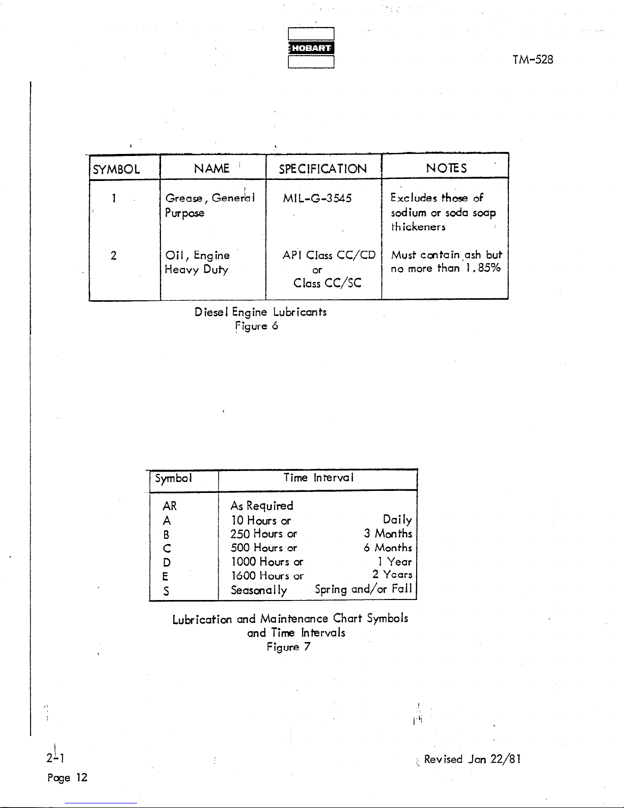
I
SYMBOL
NAME ’
SPECIFICATION
NOTES ’
1
Grease, Gene& I
MI L-G-3%5
Excludes those of
Purpose
sodium or soda soap
thickeners
2
Oil, Engine
Heavy Duty
API Class CC/CD Must ccntain,ash but
C ias9r CC/SC
no more than 1.85%
Diesel Engine Lubricants
Figure 6
1 Symbol
Time Interva I
AR
A
B
C
D
E
S
As Required
70 Hours or
Dai iy
250 Hours or
3 Months
500 Hours or
6 Months
1000 Hours or 1 Year
1600 Hours or
2 Years
Seascna I iy
Spring and/or Fall
Lubrication and Maintenance Chart Symbols
and Time Intervals
Figure 7
t
2&l
Page 12
;* Revised Jan 22/81
Page 79

I 1
TM-528
7.
Generator Maintenance
The 400-Hz generator requires no maintenance or service other than
periodic cleaning.
Clean the complete generator set when other
components of the-tow tractor are cleaned. The unit is brushless,
and bearings are permanentiy:iubricated and sealed.
A. Cleaning
The generator may”be cleaned by careful use of compressed air and/or
a good, SAFE commercial cleaner.
Steam cleaning of the generator is
no longer recommended’ because the use of steam and harsh chemical
compounds may result in damage to insulation and other generator
components.
CAUTION: BE SURE THE UNIT IS COMPLETELY DRY BEFCRE OFERATING.
WARNING: DO NOT USE A FLAMMABLE SOLVENT.
B.
Adiustment
The generator itself requires no adiustment. Adiustment procedures
for generator controls are covered in Section 2-2.
8.
Engine Maintenance
A. General
The Detroit Diesel Operator’s Manual provides detailed maintenance
instructions in the Preventive Maintenance Section.
8.
Cleaning
There are several reasons why the engine exterior should be kept clean.
Dirt on the outside will enter fuel and oil filter cases and rocker housings
when covers are removed unless dirt is removed first. A clean engine
will run cooler and develop less hot-spots.
Steam cleaning is one of the most satisfactory methods of cleaning an
eng ine, however,
there are some CAUTIONS to be observed.
CAUTION: (1) IF A CLEANING COMPOUND IS USED, SELECT ONE
WHICH IS FREE OF ACID.
(2) AVOID COMPOUNDS AND SGLUTIONS STRONG
ENOUGH TO REMOVE PAINT. ,.li
Jan 22/81 Revised
I
2-l
Page 13
Page 80

1
WARti ING:(l)
I
(3) PROTECT (ORXMOVE) ALL ELECTRICAL ACCESSORIES
SUCH AS VOLTAGE REGULATOR, ALTERNATOR, ETC.,
AND ELECTRICAL WIRING.
SEAL ALLORNINGS SUCH AS OIL FILLER TUBE, BREATHER
(4)
OFENINGS,ETC.
I
DO NOT USE A FLAMMABLE SOLVENT.
EXERCiSE CARE TO AVOID INJURY AND DAMAGE TO THE
(2)
EYES AND SKIN.
1 TM-528
./
h-l
Page 14
I
(,li
Rev ised Jan 22/8 1
i,
Page 81

SECT ION2.USTMENTflEST
1. General
,This section contains information and procedures for testing and adiusting the
I, electrical components oe the generator set.
Test and adiustment information applicable to the truck may be found in the
Truck Owner’s Manual. Use the Engine Operator’s Manual for test at-d
adjustment instructions applicable to the diesel engine.
Testing
2.
The following test procedures and information may be used ‘for testing the
generator and controls after repair or overhaul. Tests may also be useful
in troubleshooting.
NOTE: The tests which must be performed under load require the use of a
resistive and reactive loacl bank.
TM-528
A. Preoperational Test Procedures
Perform the Foiiowing checks, tests and operations before operating the
generator set:
(1) Connect the generator set to a iocd bank and use cables of the same
size and length as those to be- used in service. See l-2; Fig. 12 for
illustration of output terminal panels.
(2) Check oil level of engine crankcase.
(3) Check engine coolant level.
(4) Check engine V-be its.
(5) Check to be certain that the N lead terminal, located on the
frame behind the batteries, is securely tightened.
(6) Check all, wiring for incorrect connections, and loose or shorted
term inal lugs.
(7) Polarize the generator exciter field by momentarily applying
24-V DC to the field lead terminals. Remove the generator
control tray (bottom tray in control box) to gain access to the
terminal board mounted on the left side of! the control box
opposite the tray.
power source on the YELLOW-BLACK wire term inai and’ momentari iy touch the POSITIVE 24-V lead to the RED wire term inal.
Jan 22/81 Revised
Hold the NE GATIVE lead from the 24-V
I
‘I
2-2
Page 1
Page 82

TM-528
16
26 30 19
I6
18
1. Excitation-deenergization relay
2. Panel light
3. Push-to-build-up-voltage switch
4. Fuse, lights and excitation circuit (lOA)
5. Light switch
6. Ammeter, DC circuit
7. Oil pressure gage
8. Diaphram switch, hourmeter and
excitation circuit
9. Coolant temperature gage
10.
Hourmeter
11. Speed control switch
12.
DELETED
13. Engine speed control cable
14.
Start switch
15.
DELETED
16.
Terminal board
17. Engine running indicating light
18. Test receptacle connector
19.
No. 2 contactor indicating
light
20.
No. 1 contactor indicating light
ia
21. No. 1 contactor operating switch
22. No. 1 contactor operating switch
23. Circuit breaker, convenience output
circuit
24. Emergency stop switch
25. Hourmeter operating diaphragm
switch
26. Low fuel (engine stopped) warning
light (red
27. Push switch, low fuel system test
28. Fuse, fuel warning system test
29. Convenience output receptacle
(115-V, 400-Hz
30. Load contactor switches
operating handle
31. Fuel warning system relay
NOTE: 140Gl7P (Special) control panel is
illustrated because it includes all
standard controls as well as special
items.
.1
Engine Control Panel (140G17P Special)
1
Figure 1
),lj
2-2
Pacje 2
March 24/9g Revised
Page 83

I I
m m
I I 1 1
TM-528 TM-528
32 .
33 .
34 .
35.
36 l
37 .
38 .
39 .
40 .
41 .
42 .
43 .
Rate and gain adjustments Rate and gain adjustments
Line drop compensation switch
Cable size compensation adjustment
Cable length compensation
adi ustment
Instruction plate ”
Voltage adjusting rheostat
Fault indicating light (5)
Load contactor operating system fuse
Proteciive monitor system fuse
Protective monitor system reset switch
Test bank switch
Generator overload relay
I
I
32
38
39
40
36
33.
VOLTAGE REGULATGR TRAY
VOLTAGE REGULATGR TRAY
u 34
7
!
44.
45 .
46 ’
47 .
48 .
49 .
50 .
Jan 22/8 1 Revised
Frequency meter
AC voi’tmeter
Manual control rheostat
AC Ammeter
Automatic-manual switch
Meter switch
Line SW itch
PROTECT WE RELAY TRAY
--
GENERATOR CONTROL TRAY
Operating Controls and instruments ($eet 2 of 2)
Figure 1
(>
- 2-2
Page 3
Page 84

TM-528
CAUTION: FLASHING THE EXCITER FIELD IN THE REVERSE OF
INSTRUCTIONS ABOVE COULD RESULT IN DAMAGE
TO Dl0DE.S IN THE VOLTAGE REGULATOR.
Replace generator control tray.
1
,
(8) Position switches; and cdntrols as instructed in Sect. 1-4; Para. 4, C,
(1) thru (3) except: place test bank switch (42, Fig. 1) in TEST BANK
position, place a+omatic-manual switch (48) in MANUAL position,
/
and turn the manual control rheostat (46) knob to mid-range position.
1
(9) Check al I fuses.
I
/
I
/
(10) Check instrument panel lights.
1
I
I
(11) Check engine speed control.
Pull to OUT position and check Micro
I
switch (15, Fig. 6) to be certain it is actuated. Return control to
I
IN, idle position.
I
(12) Start engine and check all gages and meters. Check hourmeter and
engine ON indicating light.
(13) Inspect for fuel, oil, and coolant leaks.
(14) After engine has waned, place speed control switch (11, Fig. 1) in
ON position and pull speed control cable (13) OUT to FULL-SPEED
position.
8. Operational Test
‘NOTE: Tests which must be performed under load require the use of a
resistive and reactive load bank.
Test the following with the generator running:
(1) Push the press-to-build-up-voltage switch (3) momentarily. A voltage
value should be readable on the voltmeter (45) indicating that the
excitation-deenergization relay is functioning and that the generator
is delivering power to the load contactors.
(2) Use the manual rheostat (46) to vary the output voltage and check
the voltmeter by comparing the reading with a master voltmeter.
Error should not exceed 2% full scale.
.1
(3) Check frequency meter (44).
Meter should indiq:ate 401 Hz at governed
speed and no load. tiiust gover,nor, if necessyrg, to speed (1714
RPM) which will produce this frequency. Refer to Woodward Bulletin
!2-2
in chapter 6 for instructions.
Frequency meter error should not
exci+d 1 Hz.
!>
Page 4
Revised Jan 22/81
Page 85

(4)
’ (5)
(7)
(8)
(9)
(10)
1)
12)
(13)
(14)
TM-528
I
Place the line voltage switch (50) in LINE-TO-NEUTRAL position. Use
the field rheostat (46) to check the manual voltage range. Maximum voltage
s,hould be 160-V or higher. Minimum should be 95-V or less.
Place the’automatic~anual switch (48) in AUTOMATIC position and use
the voltage regulator rheostat (37) to check the automatic voltage range.
Maximum voltage should be 134-V or more, and minimum voltage should
be 108-V or less.
Check the voltage between Phase C and the contactor control switch
(21 or 22) with a For-table voltmeter to make certain that phase C goes
to the ORANGE wire terminal of the contactor switch.
With test bank switch (42) in TEST BANK position, place load contactor
control switch (21) in top ON position momentarily. Release to center
ON position. No. 1 output indicating light (20) should glow to indicate
that.No. 1 load contactor is closed. Check No. 2 output circuit in a
similar manner.
Place test bank switch (42) in AIRCRAFT position. Load contactors
should open automatically.
Apply 24-V DC between interlock terminals N and E (or F) at each of the
output term inal panels (Sect. l-2, Fig. 12).
With test bank switch (42) in AIRCRAFT position, close load contactors
Lee step (7) above3.
If interlock relays are good, contactors should
close and remain closed.
Return test bank switch to TEST BANK position
and disconnect 24-V DC power from E terminals.
With load bank, apply l/3 to l/2 full lcad and allow unit to run 15 to 30
minutes.
Ammeter (47) should indicate load amperage.
Apply a full load (140 KVA) and adjust overload resistor (2RES on generator
schematic), located in generator control tray, to give 4.0-V DC ccross
overload relay (43, Fig. 1).
If the proper load bank is not available,
resistor 2RES should be adjusted for 2.0-V DC at no load.
Check frequency regulation at no load and at full load. Droop should be
1 Hz or less. If droop is excessive adiust Qovernor in accordance with
Woodward Bulletin in Chapter 6.
Check voltage drop at output terminals without line drop compensation.
Drop should not exceed 1-V AC.
1
Jan 22/81 Revised
:
2-2
Page 5
Page 86

.’
I
m
I
TM-528
(15) With voltage regulator line drop switch (33) ON, line drop at end of cables
should be no more than 1-V AC. If drop exceeds 1-V AC, cdjust voltcge
regulator in accordance with instructions in Manual TM-232.
(16) bOperate at full, load (4049, 0.8 PF) for approximately 1 hour3
,
(a) Use meter selector switch (49) to check voltage in each phase (A, B, and
c> *
I
(b) Use mcster meter to check accuracy of voitmeter. Error should not exceed
2%.
(c) Check accuracy of ammeter with master meter. Error shpuld not exceed
4% .
(d) Observe indicated voltage for steady output.
(e) Listen for any unusual generator or bearing noises.
(17) lncrecse load to 125% to 127% rated load (505 A). Generator overload relay
(43) should trip in approximately 5 minutes. Manually reset after trip.
(78) Apply a load of 112 KVA to No. 1 output. Solid state overlocd device
should open No.
1 load contactor in 3 to 5 minutes. Overload indicating
light should be turned ON.
Press reset switch (41). Repeat check for No.
2 output.
(19) Apply a normal load to the generator.
NOTE: Return the generator to normal loaded condition after each of the
following tests by pressing reset switch and closing load contactors.
(20) Check overvoltage protective circuit. It should function to open load
contactor at 130 to 134-V.
Overvoltage indicating light should be
turned ON.
(21) Check under-voltage protective circuit. It should function to open locd
contactor at 103 to 93-V.
Under-voltage indicating light should be
turned ON.
(22) Overpower hydraulic governor to check overfrequency protective circuit.
Re.lay should trip at 415 to 425 Hz.
Overfrequency indicating light should
be turned ON.
(23) Decrease engine speed to check under-frequency protective circuit. Relay
should function at 375 to 385 Hz. Underfrequencyl’ilixf icating light should
be turned 0 N .
tz-2
Page 6
1,
Revised Jan 22/81
Page 87

’
1
1
TM-528
NOTE: Push and hold push-to-build-up-voltage switch (3) to keep generator
energized while making underfrequency test.
(24) Check air cleaner indi,cator. Use a piece of cardboard to restrict air intake
into the air,cleaner. As intake is restricted the red flag should rise in the
I
indicator chamber. lnlcrease air,restriction until indicator flag is locked
in top position. I
Remove cardboard and press reset button on bottom of
indicator to release flag.
I
(25) Check engin& oil pressure: Should be 30 PSI (207 kPa) or more at rated speed
/
(1714 RPM).
(26) Check engine coolant temperature. Should be near 180 deg F to i 90 deg F
(82’ C to 88O C) dependirig upon ambient temperature. ’
(27) With locd applied, remove fuse (40). If fuse interlock relay is operating
properly, the load contactor will open immediately.
(28) Check overspeed governor. Governor should function to close the fuel
valve and stop the &ngine when speed reaches 1900 RPM to 2025 RPM.
(29) Perform the voltage tests I isted in Fig. 2 using the optional test box
(Part No. 388318-4). This test box is available from Hobati Bro:hers
Company at a nominal charge.
Connect the test box plug to the test
receptacle (18, Fig. 1). Connect a VOM to ihe tip jacks on the test
box. Perform tests at normal operating speed and NO load. Test bcnk
switch (42) must be in TEST BANK position. The test box has each switch
position marked with test condition (control settiogs, etc.) and voltage
values.
Switch positions 17 and 19 are not used.
NOTE: It will be necessary to bold locd contactor switches (21 end 22)
in top ON position for K to R, and K to T tests.
(30) Position test bank switch to AIRCRAFT.
3. Pdiustment .
Minor adiustments may be performed by operating personnel; however, complicated mechanical ard electrical adiustments should be attempted by experienced
electricians and mechanics only.
A. Engine Governor
The diesel engine governor has been correctly adjusted at the factory to
drive the generator at a speed which will provide!,an output of 401 Hz
under na load and 400 Hz under load conditions.l,‘iIf the governpr is
replaced, adjust it in accordance with Woodward Governor Instruction
Bulletin which is supplied ‘with this manual in Chapter 6.
Jan 22/81 Revised 1
2-2
0
Page 7
Page 88

L
m
1
TM-528
B. Generator
The 460-H= generator and the ekciter are.both brushless type and require no
odiustment.
I
C. Generator Control Pdiusfrr!enfs
The following items may require adjustment at some time during the life of
the equipment.
L
1
2
3
4
5
6
7
a
9
10
17
12
13
14
15
16
17 *
18
1 ?
: KtoM
KtoP
KtoS
K A
t0
! KioB
H S
t0
KtoZ
DtoF
; vtox
j Ktob
! KtoE
: KtoR
i KtoY
; Ktod
1 KtoT
i K to N
!
K to G
i
Test
Nom inal Vo itage
Phase ‘A
I
/ 115VAC
Phase B
j 115 v AC
Phase C
115V AC
P.M Fuse
/
12 ‘? DC
FIR & OL Battery Voitcge :
12 V DC
PM Contacts
: 115VAC
No. 1 PIR Coil
I
24V DC
Exciter Input (F+, D-) approx. 17 V DC
Regulator Output (X+, V-) approx. 40 V DC
No. 1 Contactor Phase C
OL Contacts
No .
1 Contactor Switch
No. 2 PIR 6il
No. 2 Contactor Phase C
No. 2 Gntactor Switch
Battery Vo itage
EDR & Full Throttle Sol.
I
I
I
L
115 V AC
OV DC
115 V AC
24VDC
115 V AC
115 V AC
24VDC
24V DC
* Switch positions 17 and 19 are not used.
Normal Test Values at Test Receptacle Connector (7 PL)
Figure 2
42 -2
Page a
Revised ja” 22/a 1
Page 89

.
(1) Adiust manual voltage control variable resistor
TM-528
The adiustment of this resistor (1, Fig. 3) determines the maximum generator
‘output voltage obtainable when using the manual control rheostat for voltage
control. To adjust maximum voltage potential, proceed as follows:
4
,
(a) Loosen slrider-band clamping screw (D).
(b) Move the!,slider-band toward the single wire end (C) of the resistor to
increase voltage potential.
Move the band toward the double wire end
(E) (two wires connected) to decrease voltage potential.
(c) Tighten slider-band clamping screw when adiustment is completed.
(2) Adiust generator overload relay ballast resistor
The trip point of the overload relay (43, Fig. J) is determined by the
adjustment of one of the bai last resistors (2) shown in Fig. 3.
NOTE: This resistor is identified as 2RES on Schematic Diagram.
(a) Loosen slider-band clamping screw (F, Fig. 3).
(b) Position slider on resistor (2) to produce 4.0-V DC across the heater
element of overload relay (43, Fig. 1) when the generator is operating
at full rated load (140 WA). If the proper iood bank is not available,
adiust resistor 2RES for 2.0-V DC at no load.
C
J. Manual controI,voltage potent,&1 adjusting resistor
2. Exciter field ballast- resistors
Jan 22/8J Revised
:
E xc itat io n Resistors I
Figure 3
2-2
Page 9
Page 90

(c) Tighten clamping screw.
(3) Adjust 11,5-V AC-voltage regulator
When a voltage regulator is f,Jrst put into service, or when output (generatorto-a’ircraft) cables are changed, the regulator may require up to five separate
cdiustments. The five adiustments are for generator output voltage value,
dcmping gain, dcmpingjrate, iine drop compensation gain, line drop compensation rate. See F
aiiustment.
(a) Adiust generator output voltage
This is a relatively easy adiustment to make. With the generator running
at a rated speed (1714 RPM) and rated cycles-per-second (400 Hz), rotate
the rheostat knob (1) CLOCKWISE to INCREASE voltage and COUNTER-
CLQCKWISE to DECREASE voltage. Observe the AC voltmeter (45, Fig.
and adiust output voltage to 115-V AC.
igure 4 for identification of components used for regulator
TM-528
1)
(b) Ai just cable length and size compensation rheostats.
These two adjustments should be made together. Switch (4,. Fig. 4) must
be ON. Proceed as foIiows:
(aa) Adjust the rheostat (2) to point to the length, in feet, of output
ccbie being used.
mounted behind the rheostat knob.
(bb) Adi t h
(cc)
(dd)
‘us r eostat (3) to point to the size of cable being used. Various
cable sizes ate also indicated on a plate behind the rheostat knob.
With generator running (no load), check output voltage value,
which should be exactly 115-V AC. if not, adjust in accordance with
Para. 3, C, (3), (a) above.
Connect the locd bank and position test bank switch (42, Fig. 1)
to TEST BANK. Apply a full load to the generator. Observe AC
vo Itmeter;
from 115-V AC, adjust rheostats (2) and (3) slightly to obtain a
voltage of 115-V AC, or as close to this vaiue as possible. Turn
knobs CLOCKWISE to INCREASE voltage bnd COUNTERCLOCKWISE
to DECREASE. Turn each knob a small amount at a time to determine
which rheostat is having the most effect on output voltage and requires
ad i ustment .
if the vo.itage observed varies more than 1% (plus or minus)
Various cable lengths are indicated on a plate
t
t
‘2-2
Page 10
Revised Jan 22/8J
‘8
Page 91

Adjust damp and rate potentiometers. (See 7, Fig. 4 for potentiometers
(4
location in voltage regulator.)
TM-528
Refer to Fig. 5.
Damping adiustments are very delicate and shouid not
be attempted unless the generator output average phase value varies
more than 1 Volt, or output voltage is unstable. Damp and rate adjust-
I
I
I
ments must be m+e in conjunction with each other because the adjustment of one may affect the other. For example, improving the response
by adjusting the damp potentiometer (1) may affect the stability as adiusted
by the rate potentiometer (2). Pdiust as follows:
Jan 22/81 Revised
1. Voltage adjusting rheostat
2. Cable length compensation rheostat
3. Cable size compensation rheostat
4. On-off switch, line-drop compensation
5. Fuse (5 A)
6. Fuseholder
7. Damp and rate adjustment potentiometers
Voltage Regulator Adiustment
Figure 4
2-2
Page 11
Page 92
I 1
m
I I
TM-528
I
I
(ap) if dunp and rate cdiustments have been disturbed (changed from
factory setting), or if the regulator has been repaired, loosen
locking nuts and set both potentiometers to mid-position (halfway
between full CLOCKW JSE and Full COUNTERCLOCKWISE).
1
(bb) Connect the generator output to a balanced, three-phase load of
30 ki iowatts.
(cc) With generator running at 115-V AC no iocd, operate the
contactor on-off switch.
If the average phase voitcge changed
more than 1 .O Volt, or if output is unsteady, cdiust damp and
rate.
(dd) Turn the dcmp (J’, Fig. 5) cdjusting screw CLOCKWISE to improve
response.
Turn COUNTERCLOCKWISE to improve STABILITY.
Generally the best cdiustment is approximately 3/4 of full CLOCKWISE
travel.
(ee) Turn the rate (2) adiusting screw to near full COUNTERCLOCKWISE
. . .
poslrlon.
Turn the screw siowiy CLOCKWISE unt ii the voltage
output abruptly becomes STE ADY. Continue turning the screw
CLOCKWISE 5 deg to 10 deg past this point for best rate adiust-
ment.
(ff) Tighten cdiusting screw locknuts after adjustment is completed.
(gg) Position test bank switch (42, Fig. 1) to AIRCRAFT.
D. Basic Engine Adiustments
Adiustment procedures applicable to the diesel engine are incivded in the Detroit
Diesel Operation and Maintenance Manual.
E. Governor Adiustment
, Refer to Detroit Diesel Operator’s Manual and Woodward Governor Bulletin in Chap-
ter 6
for high (governed) speed and droop odiustments. Refer to instructions
be low for id ie speed adiustment .
F. Governor Speed Control Linkage Adjustment
Refer to Fig. 6.
This mechanical linkage must be adiusted to allow the governor
speed control arm (17) to move from no-fuel (stop) position, through idle, to full
governed speed position.
The function of the solenoid (5) is to hold linkage in
governed speed position when the speed control toggle swttch (11, Fig. 1) has
been placed in ON position and the speed control (13) h& been pulled *OUT to
t
full speed position.
To adiust linkage, proceed as follows with engine stopped.
,2-2
Revised Jan 22/a 1
!,
Page 12
Page 93

m
I 1
TM-528
I
1
DAMP (Gain) - (Affects response
‘i--Y,
and stab i I ity)
1
1
ADJUSTING SCREW DiRECTiON
OF ROTATION.
1
I
1 0
@
0
@
RlO
R14 1
RATE
DAMP
f
I
,,
CLOCKWISE - Makes regulator
MORE RESPONSIVE, LESS
STABLE (less steady).
COUNTERCLOCKWISE - Makes
regulator MORE STABLE (steadier),
LESS RESPONSIVE.
Best ad i ustment approximate iy 3/4
of full travel CLOCKWiSE.
s
RATE - (Affects stability)
ADJUSTING SCREW DIRECTION
OF ROTATION
Regulator will likely be UNSTABLE
if cdjusting screw is at either limit
of adiustment
- CLOCKWISE or
COUNTERCLOCKWISE. From a
point near full CO UNTERCLOCKWISE position, turn the screw
CLOCKWISE until a point is
reached where the voltage regulator abruptly becomes STEADY.
Best adjustment for the system is
usual iy 5 deg to 10 deg beyond
this point in a CLOCKWISE
direction .
Voltage Regulator Damping Adjustments
Figure 5
t
(,Li
Jan 22/81 Revised
:
2-2
Page 13
Page 94

I
w
1
(1) Pdiust switch operating disc position.
TM-528
(a) Disconnect clevis (14, Fig. 6) by unhooking spring (8) and removing pin (10).
(b) Disconnect governor lever (17) by removing pin (16).
(c) Move disconnected linkage and disc (4) toward the solenoid (5) until the
solenoid plunger bottoms in the solenoid housing. The disc (4) ,should
contact the Micro&witch button (15) just before the plunger bottoms.
if the disc will not touch the switch button, or if its contact with the
switch prevents plunger bottoming, adjust disc position by adding or
removing 5/16 inch (8 mm) flat washers (18) as required.
(2) Adjust solenoid linkage
(a) With solenoid plunger linkage disconnected as above in (l), (a) and (b),
hold the governor lever in fuiiTspeed position (toward soienoid).
(b) Move solenoid plunger to full-speed position (bottomed in housing).
(c) loosennut (1) and adjust rod (3),so that yoke (2) may be connected to
governor lever (77) with pin (16).
(d) install pin (16 and secure with cotter pin. Tighten nut (1).
NOTE: Some cushion is desirable in this adiustment, which means
that the governor lever should reach full speed position when
the plunger is about l/32 to l/l 6 inch (O&8 to 1.6 mm) away
from bottoming in the solenoid housing.
‘(4 M
anuaiiy actuate linkage to ‘make certain it operates freely between
no-fuel position and full-speed position. Be sure Micro switch is
..
turned ON in full-speed position..
(f) Connect cievlis (14) and Jink (9)
with pin (10) and connect spring (8).
(3) Adjust engine idle speed.
NOTE: A stroboscope is required for this adiustment.
!2-2
(a) Before odiusting idle speed,
lift the hinged stop (located on the engine
control panel beh,ind the speed control knob) UP and push the speed
control fully IN to no-fuel position.
if necessary, reposition the speed
control cable housing (7)
in clamps (6) so that the cable extends forward
enough to al low the governor linkage to go to no-fuel position when the
two adiusting nuts (12) are full threaded on rod (l’?).
Rev ised Jan 22/a 1
,Page 14
Page 95
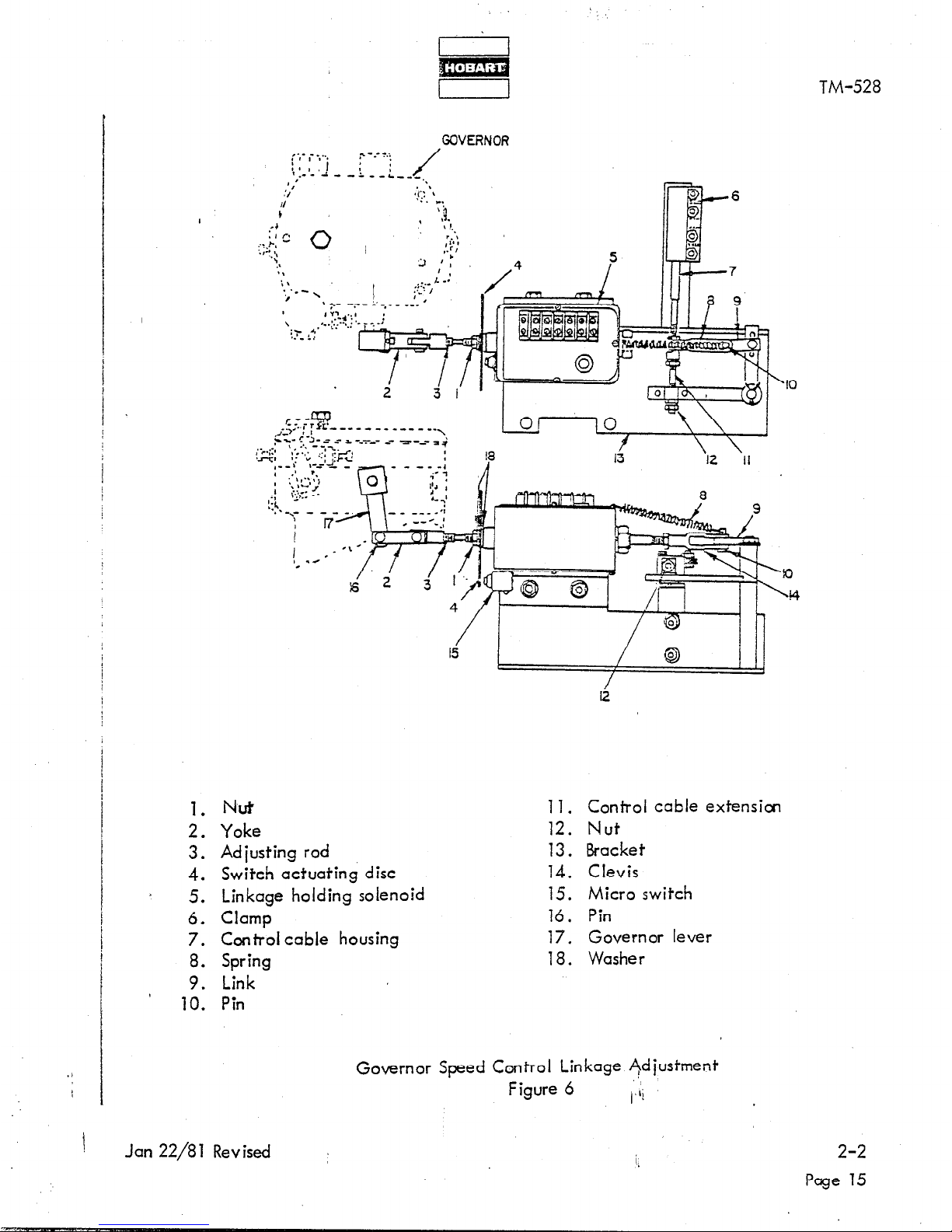
m
i-?
TM-528
GOVERNOR
;;- ,- ;-.
,- - .- ?.i
\’ / I ,-L
: I
.- - / - -& e-L-,-
‘#
,
* ‘I\
l/
a.1” ,
,,
.:‘. “.
1. Nut
2. Yoke
3. Adjusting
rod
4. Switch actuating disc
5. Linkage holding solenoid
6. Clamp
7. Control cable housing
8. Spring
9. Link
10. Pin
11.
Control cable extension
12. Nut
13.
Bracket
14.
Clevis
15.
Micro switch
16.
Pin
17.
Governor lever
18.
Washer
,
I
i
./
Governor Speed Control Linkage Adjustment
Figure 6
Ii
Jan 22/8 1 Revised I
i.
2-2
Page 15
Page 96

i-l
1
(b) Pull the speed control knob out suffic
the,n push speed control IN.
(o) Start engine’.
(d) Adiust engine idle speed by adiusting nuts (12) on rod (11). Thread nut
ONTO rod to increase speed. Back it OFF to decrease speed. Use a
stroboscope and adjust speed to 825 RPM plus or minus 25 RPM.
(e) Lock adjusting nuts (7,2) securely.
(f) Check all I k
position.
(4) Ad just engine governed (high) speed
(a) Start engine.
switch (11, Fig. 1) in ON position and pull speed control (13) OUT to
ful I speed position.
in age
All
for free travel from no-fuel position to ,full speed
ow it to idle until warmed, then place speed control
Press push-to-build-up-voltage switch (3).
I
iently to fl
ip the hinged stop DOWN,
TM-528
(b) See Woodward Governor Bulletin in Chapter 6. Use high speed cdjusting
screw on Woodward governor to cdiust speed at approximately 1714 RPPA.
(c) Position test bank switch (42, Fig. 1) to TEST BANK. To fine-adiust
engine speed apply a load to the generator and adjust speed so that
exactly 400 Hz is indicated on the frequency meter (44, Fig. 1).
(d) Position test bank switch to AIRCRAFT.
B -2
Page 76
Revised Jan 22/8 1
I>
Page 97

CHAPTER 3. TROUBLESHOOTING
TM-528
SECT/ON ‘I. TROUBLESHOOTING PROCEDURES
1. General
,
A.
Troubleshooting ‘is an orderly, process of checking and eliminating possible
causes of trouble until the exact cause of a trouble is found.
As a rule,
the best place to!start looking for the cause of a trouble in a circuit or
system is at the source of power or supply.
Continue testing or checking
the circuit or system,, step-by-step, in an orderly. manner, until the
cause of trouble is located.
8.
This chapter provides information useful in diagnosing ard correcting
certain troubles which cause unsatisfactory operation or failure of the
equipment.
C.
Minor troubles may be remedied by the operator; however, major repairs
must be undertaken by experienced mechanics and electricians only.
D,
Use of the optional test box is recommended for troubleshooting.
2. Troubleshooting Chart
A. Description
The troubleshooting chart lists information under three headings as follows:
(1) Trouble, Symptom, and Condition
(2) Probable Cause
(3) Test, Check, and/or Remedy
B.
Use of the Troubleshooting Chart
(7) A troubleshooting chart is furnished to provide maintenance and repair
personnel with a time-saving guide for locating trouble. To use the
chart, proceed as fo I lows:
(a) Locate thesymptom of trouble in the Trouble column.
(b) Check th
e ro a
p b bl
e causes of trouble in the Probable Cause column.
(c) Test, check, repair, or correct the troubie as indicated in the
Remedy column.
Jan 22/8 1 Revised
:
3-l
Page 1
Page 98

TM-528
(21
(3)
(4)
If the cause of a trouble is an uncommon one and cannot be located by use
of the chart, the only alternative is to start at the source of power or supply
ar+check the affected circu,it or system completely. Use schematic and
connection diagrams which are supplied with this manual.
I
Electrical components mentioned in the troubleshooting chart are identified
by.a noun ncme and a Corresponding symbol which allows the user to identify
the item more easily on schematjc diagrans.
It is assumed that wiring and connections in defective circuits have been
thoroughly checked before condemning any other components.
NOTE: Reference symbols (5S, etc.), used in the Troubleshooting
Chart, are identified on Schematic Diagrams.
3. Wiring Diagrams
All connection and schematic wiring diagrams applicable to the generator set
are supplied in Chapter 6 as pert of the information package.
5
-
T
Page 2
Revised Jan 22/87
Page 99

Diesel Engine (Continued)
Trouble, Symptom & Condition .Test or Inspection
Corrective Action
TM-528
1. Engine will not start. Starter a. Loose battery or ground Clean and tighten all
will not crank engine:
, connection. connections.
I
b. Defective or discharged Test all batteries. Replace or
battery. recharge as required
I
c. Defective start switch
Jumper the start switch (14,
(3PB). Fig. 5). If starter cranks engine,
replace switch
d. Air shut-down valve closed Reset air valve.
e. Defective starter switch
Check starter solenoid and
solenoid or defective starter. ’ Send old starter to
starter. overhaul.
2. Engine will not start. Starter
cranks engine normally.
3. Engine runs. Engine “ON”
indicating light (1 G) does not
glow.
a. Fuel not reaching fuel
w-w.
b. Mechanical defect in
engine fuel system.
a. Lamp (bulb) defective.
b. Fuse (1 FU) “blown”.
Check to be certain that there is
sufficient diesel fuel in tank and
that the mechanical shut-off
valve (at tank) is open. Check
for restrictions in fuel line from
tank to fuel pump.
Refer to Detroid Diesel Engine
Manual.
If hourmeter is operating,
replace lamp in ON light (17,
Fig. 5).
Visually inspect fuse (4, Fig. 5.
Replace if blown.
c. Defective oil pressure
switch (1 OPS).
Jumper the switch (8, Fig. 5)
while engine is running. If light
(IG) will then operate, replace
switch.
\
March 24/95 Revised
3-1
Page 3
Page 100

&J!&
1
TM-528
(4) Defective be I lows
assembly.
4. Engine runs.
Engine A. Defective lamp (bulb).
ON light (1G) does
not operate.
B. Fuse (IFU) “blown”.
(4) Check to make certain it
will operate properly if
normal oil pressure is
delivered to it. Replace
bellows 1-2; 1, Fig. 4,
if defective .
A.
If hourmeter is operating, re-
place lamp in ON light(T7,
Fig. 5) n
B.
Visually inspect fuse (4, F,ig.
,5). Repiace.
C. Defective oil pressure
switch (10 PSI.
C. Jumper the switch (8, Fig. 5)
while engine is running . If
light (1G) will then operate,
replace switch.
./
1
(‘Ii
3\1
Troubleshooting Chart (Sheet 2 of 9)
Figure
1 Revised Jan
22/8 1
Page 4
(>
_.-
TROUBLE,SYMPTOM,
AND CONDITION
PROBABLE CAUSE
TEST, CHECK, AND/OR REMEDY
DIESEL ENGINE (CCNTINUED)
2. Engine will not
D . Ambient temperature too D. Use starting aid.
start. Starter,
low for normal engine
,
cranks engine
starting’ procedures.
normal ly . (Con t’d)
I
3. Engin’e starts and
A. Air shut-down va ive not
A. Check and repair as follows:
runs.
Engine ON
being latched open by
light glows. Engine
bellows assembly.
stops as soon as
star~t switch is re-
(1) Emergency stop switch
(1) Place in OFF position.
leased.
10-S is ON .
(2) Foreign material, block-
(2) Check restricted fitting at
ing oil supply to shut-
cylinder block for dirt and
down oil system.
foreign material. Clean a
required.
(3) One of the safety
devices is defective,
leaking oil, and preventing pressure
build-up.
(3) Check all safety devices ir
shut-down system. Replac
any defective device.
 Loading...