

Hobart 140G17K, 140G17P Operation And Maintenance
TM-528
Revised 032495
OPERATION AND MAINTENANCE
MANUAL
for
TRUCK/TRAILER-MOUNTED GENERATOR SET
140-KVA, 400-HZ, 115/200-V AC, 3-PHASE
with
DETROIT DIESEL ENGINE
TYPE 8V-71N
5566B
Model Numbers
140G17K (Truck Mounted Unit)
140G17P (Trailer Mounted Unit)
140G17P (With Special Accessories)
Manufactured by
L
.!
HOBART BROTHERSCOMPANY "
POWER SYSTEMS DIVISION
j”i
TROY, OHIO 45373
1
U.S.A.

SAFETY INSTRUCTIONS AND WARNINGS FOR ELECTRICAL POWER EQUIPMENT
ELECTRIC SHOCK can kill. Do not touch live electrical parts.
ELECTRIC ARC FLASH can injure eyes burn skin cause equipment damage and
I
ignite combustible material. Do not use power cabies to
brekk load and prevent tools from causing short circuits.
IMPROPER PHASE CONNECTION,! PARALLELING, OR USE can damage this and attached
equipment.
IMPORTANT: - Protect all oderating personnel.
Read, understand, and follow
ail instructions in the Operating/Instruction Manual before
installing, operating,
or servicing the equipment.
Keep the manual
available for future use by all operators.
A.
GENERAL
Equipment that supplies electrical power can cause serioueinjury or death,
or damage to other equipment or property.
observe all safety rules and take precautionary actions.
The operator must strictlv
Safe practices
have been developed from past experience in the use of power source equipment.
While certain practices below apply only to electrically-powered equipment,
other practices apply to engine-driven equipment,
B.
SHOCK PREVENTION
Bare conductors,
electrically-live
or terminals in the output circuit, or ungrounded,
equipment can fatally shock a person.
and some practices to both.
Have a certified
electrician verify that the equipment is adequately grounded and learn what
terminals and parts are electrically HOT.
Avoid hot spots on machine. Use'
proper safety clothing, procedures, and test equipment.
The electrical resistance
dangerous currents to
equipment, do not work in damp areas.
dry wood,
use insulating gloves when dampness or sweat cannot be avoided.
of the body is decreased when wet, permitting
flow through it.
When inspecting or servicing
Stand on a drv rubber mat or
Keep clothing dry, and never work alone.
./
1
1. Installation and Grounding of Electrically Powered Equipment
Equipment driven by electric motors (rather than by diesel or gasoline
engines) must be installed and maintained in accordance with the ?lational
Electrical Code, ANSI/XFPA 70, and other applicable codes.
A power
disconnect switch or circuit breaker must be located at the equinment.
Check the nameplate for volta e,
only 3-phase power is
availab e,
to only two wires of the 3-phase line.
frequency, and phase requirements.
F
connect any single-phase rated equipment
DO NOT CONNECT the equipment
grounding conductor (lead) to the third live wire of the 3-phase line
this makes the eauipment frame electrically HOT, which can cause a fa;aF
-iniT&.-Always connect the grounding lead
if supplied in a power line cable,
to tne grounded switch box or building ground,
separate groundin
of the grounding
situation.
details.
Refer to the National Electrical Code .ANSI/NFPA 70 for
Do not remove plug ground prongs. Use correctly mating
lead.
!T
ead will be adequate for the worst
Ensure that the current
-m-e-
If not provided, use a
(am erage)
P
ault current
capacity
receptacles.
2.
Output Cables and Terminals
Inspect cables frequently for damage to the insulation and the
connectors.
not overload
Re lace or repair cracked or worn cables immediately. Do
ca les. 1
Do not touch output terminal while equipment is
energized.
Service and Maintenance
3.
,
This equipment must be maintained in good elec&?ical and mechanical
condition to avoid hazards stemming from disrepair. Report,any
equipment defect or safet
use of the eluigm ent unti its safety has been assured.
should be ma e'
y qualified personnel only.
hazard to the supervisor and di.z;.z;fmre
1
>
If
Instruction 910082
Feb 25/86 Revised
Page 1
?I.
TC)XIC FUME PREVENTION
E.
c
- .
Before inspecting or servicing eledtricallp-powered equiment,
take the following precautions:
a. Shut OFF all power at the
disconnectin
before inspecting or servicing the
f
switch or line breaker
equ pment.
b.
Lock switch OPEN (or remove line fuses) so that power cannot be
turned ON accidentally.
c. Disconnect power to equipme.nt if it is out of service.
d. If troubleshooting must be 'done with the unit ener
another person present who is trained in turning o
9
zed, have
f the equipment
and'providing or calling far first aid.
FIRE AND EXPLOSION PREVENTION'
Fire and explosion are caused hy electrical short circuits, combustible
material nea,r engine exhaust &ping, misuse of batteries and' fuel, or
unsafe operating or fueling conaitlons.
1.
2.
3.
Electrical Short Circuits and Overloads
Overloaded or shorted equipment can become
hot enough to cause fires
either by self destruction or causing nearby combustibles to ignite.
For electrically-powered equipment, in particular,
"1
rotide primary
~input protection to remove short circuited or heavi y overloaded
equipment from the line.
Batteries
Batteries may explode and/or give off flammable hydro en
and arcing from a ruptured battery can cause fires
an
3 ad%%oni?e acid
failures.
When servicing, do not smoke, cause sparking, or use open
flame near the battery.
Engine Fuel
Use only approved fuel container or fueling system.
Fires and
explosions can occur if the fuel tank is not grounded prior to ;g duping
fuel transfer. Shut unit DOWN before removing fuel tank cap.
completely fill tank, because heat from the eouipment may cause fuel
expansion overflow.
Remove all spilled fuel IMMEDIATELY, including any .
that penetrates the unit. After clean-up,
fumes away with compressed air.
open equipment doors and blow
Carbon monoxide - Engine exhaust fumes can kill and cause,health problems.
Pipe or vent the exhaust fumes to a suitable exhaust duct or outdoors.
Never locate engine exhausts near intake ducts of air conditioners.
BODILY INJURY PREVENTION
Serious inju
Y
can result from contact with fans inside some equipment.
Shut DOWN sue
equipment for inspection and routine maintenance.
When
equipment is in oneration use extreme care in doing necessary troubleshooting
and adjustment.
Do not remove guards while equipment.is operating.
MEDICAL AND FIRST AID TREATMENT
First'aid facilities and a qualified first aid person should be available
for each shift for immediate treatment of all injury victims. Electric
shock victims should be checked by a ph
sician and taken to a hospital
immediately if any abnormal signs are
o served. i:
EMERGENCY FIRST AID I
Call physician immediately.
Seek additional assistance and use First Aid
techniques recommended by American Red Cross until medical help arrives.
./
;EzREATHING IS DIFFICULT give oxy en,
FOR ELECTRICAL SHOCK, turn o
F
if available, and have victim lie
f power, Remove victim; if not
breaihing, begin artificial respiration, preferably mouth"to-mouth. If
I no detectable pulse,
Squad immediately,.
begin external heart massage. Calll.$mergency Rescue
G.1 EQUIPMENT PRECAUTIONARY LABELS
h:;E:::e 3 YeCau==ona
Order and
abels
ry Aabe's on the equi
that cannot be easily rea
F
ent monthly.
.
!,
Page 2
Instruction 910082
Revised Feb 25/86
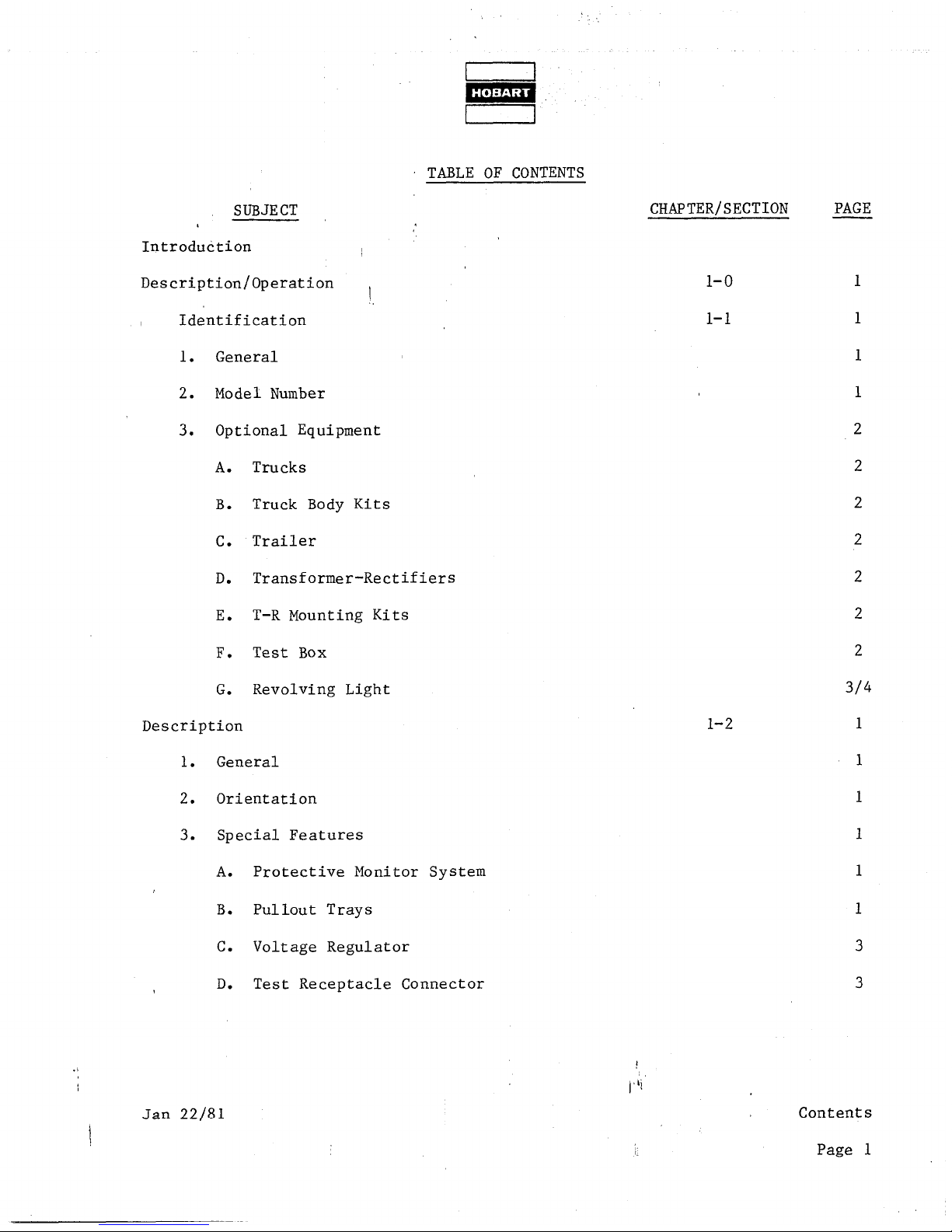
TABLE OF CONTENTS
SUBJECT
I
Introduction
,
Description/Operation ,
/
Identification
1.
General
2. Model Number
3.
Optional Equipment
A.
Trucks
B.
Truck Body Kits
C.
Trailer
D.
Transformer-Rectifiers
E.
T-R Mounting Kits
F.
Test Box
G.
Revolving Light
Description
1.
General
2.
Orientation
3.
Special Features
A. Protective Monitor System
B.
Pullout Trays
C. Voltage Regulator
D.
Test Receptacle Connector
1
./
/‘Ii
Jan 22181
1
CHAPTER/SECTION
PAGE
1-o
1
l-l
1
1
1
2
2
2
2
2
2
2
314
l-2
1
1
Contents
Page 1
TABLE OF CONTENTS CONTINUED
SUBJECT
CHAPTER/SECTION
E . Test Box
,
l-2
F. Dual Output
I
).
4., Canopy
5. Engine, Generator and Controlls Assembly
A. General
3. Generator
C. Engine
D. Governor
E. Engine Safety Shutdown System
(1) General
(2) Air shutoff valve
(3) Engine fault sensing devices
(a) General
(b) Emergency-stop solenoid valve
F. Air Cleaner
G. Control Box
(1) Voltage regulator tray
(a) Gantrols
(b) Protection
(c) Components
(2) Protective relay tray
1
Contents
Page 2
) b’i
TM-528
PAGE
3
3
3
6
6
7
9
9
10
10
10
10
12
I;
Revised Jan 22/81
I
i
i
/
!
/
I
/
f
I
!
/
I
,
I
/
!&
1
TABLE OF CONTENTS CONTINUED
SUBJECT
CHAPTER/SE CT ION
‘, (a) S
ensing relays 1’
(b) Protective monitor module
I
,I
(c) indicating I ights
(d) Plug interlock relay
(e) Test-bank switch
(f) Resistor
(g) Fuse interlock relay
(h) Connector
(i) Diode,
capacitor and terminal board
(k) Overload relay
(I) Fuses
(3) Generator control tray
(a) Resistors
16
(b) Generator output meters 16
(c) Meter and I ine switches
16
18
18
18
(d) Receptacle connect0 r
(4 Tray
(f) Manual voltage control
H. Engine and Generator Control Panel
(1) Engine gages and meters
(a) 0 i I pressure gage and diaphragm switch
l-2
1
Li
I t
TM-528
PAGE
12
12
14
14
14
15
15
15
15
15
15
16
18
18
18
Jan 22/8 T Revised
Contents
Page 3
TABLE OF CONTENTS CONTINUED
TM-528
SUBJECT
I (b) Ammeter : ,
(c) Temperature gage
(d) Hourmeter
(2) Panel lights
(3) Indicating I ights
(a) Engine ON indicating light
(b) locd contactor indicating I ights
(4) Switches
(a) Air valve (starting) switch
(b) Starter switch
!_
,
CHAPTE R/SE CT 10 N
1-2
PAGE
18
20
20
20
20
20
20
21
21
21
(c) Speed control switch
(d) Light switch
(e) Load contactor control switches
(f) Push-to-build-up-voltage switch
(5) Excitationtdeenergization relay
(6) Fuse
(7) Test receptacle connector
(8) Speed control cable
(9) Cold weather starting aid
(10) Terminal boards
.I
J. Special Engine and Generator Control Panel
t
l,‘i
21
21
21
22
22
22
22
22
22
23
23
) General
!
Contents
Page 4
(1
23
Revised Jan 22/81
I
m
1
TABLE OF CONTENTS CONTINUED
SUBJECT
(2) Receptacle, connector and circuit breaker
I
<’
(3) Emergency-stop switch
,(4) Ho urme ter d iaphragm switch
(5) Locd contactor switches operating handle
(6) Low fuel warning and shutdown system
K. Power Module
(1) Capacitor
CHAPTER/SECTION
1-2
(2) Line-drop current transformer
(3) Ammeter current transformer
(4) Locd contactor
(5) Diode panel
(6) Resistors (line drop)
(7) Overload current transformer
(8) Overlood board
(9) Indicating light relc
(10) Terminal board
’ L. Output Terminal Panel
Preparation for Use
,l . Generator Set
A. General
B. Inspection/Check
ys and blocking diode
l-3
C. Output Cables Installation
Jan 22/81 Revised
TM-528
PAGE
23
23
23
23
25
25
25
25
25
26
26
26
26
26
28
28
28
1
1
1
1
3/4
Contents
Page 5
TM-528
SUBJECT
CHAPTER/SECTION
PAGE
TABLE OF CONTENTS CONTINUED
(l), Cable requirements
3
(2) Cable connection ’
Operation
1. General
2. Operating the Truck
A. General Operating Instructions
8. Starting the Truck Engine
C. Positioning the Truck
3. Operating the Trailer
A. General
B. Operating the Brakes
C. Drawbar
4. Operating the Generator Set
A. General
8. Connecting Output Cables
C. Preparation for Power Delivery
(1) Voltage regulator trcy
(2) Protective relay tray
1 (3) Generator control tray
(4) Engine and generator control panei
D. Normal Engine Starting
1
E. Cold Weather Engine Starting
Contents
Page 6
1-3
3/4
3/4
l-4
1
1
1
1
1
2
2
2
2
2
2
2
3
3
3
3
4
4
,
4
(#Ii
7 :
Revised Jan 22/81
I
m
I 1
TM-528
I
I
TABLE OF CONTENTS CONTINUED
SUBJECT
CH APTE R/SE CT IO N
PAGE
--
F., Power Delivery (Automatic Voltage Cantroi)
l-4
9
G. Power Delivery (Manual Voltage Gntrol)
H.. Stop Power Deliver&
10
10
J. Stop Engine
K. Emergency Stop (Special)
5. Operating Instructions for Optional T-Rs
A. Transformer-Rectifier Operation
(1) Direct current power delivery
(2) Simultaneous 28.5-V and 35-V DC power delivery
(3) Simultaneous 28.5-V DC and 115-V AC power delivery
(4) Simultaneous 35-V DC or 112-V DC
-
Servicing
2-o
Maintenance
2-l
1. General
10
10
11
11
11
11
12
12
2. Maintenance Schedule
1
A. General
1
B.
Maintenance Schedule Check Sheet
1
C. Time lntemais
1
D. Identification of Interval Periods
1:
3. Air Cleaner Cartridge Replacement
3
A. Removal
,
3
ii
B. Installation
4
Jan 22/8 1 Revised :
i.
Contents
Page 7
TM-528
TABLE OF CONTENTS CONTINUED
SUBJECT CHAPTER/SE CT ION
PAGE
4. Electrical System (24-‘V and
I
A. Lights
B. Fuses
C. Wiring and Gpnections
D . Battery Service
(1) General
12-W DC) , 2-l 5
(2) Battery location and accessibility
(3) Battery care
(4) Liquid level
(5) Cleaning the battery
5. Electrical System (115-V AC)
A. Monitoring Instruments
B. Indicating Lights
C. Protective Relays
D. Wiring and Connections
6. Lubrication
A. General
B. AC Generator
C. Generator Controls
D. Diesel Engine
(1) Lubrication schedule
t:
ontents
5
5
5
s 5
5
5
5
7
7
8
8
8
8
9
9
9
1
)“i
9 .
-
!,
Revised Jan 22/81
Page 8
SUBJECT
.
w
1
I
TM-528
TABLE OF CONTENTS CONTINUED
CHAPTER/SE CT IO N
PAGE
I
(2) Oil specification
2-l
9
I
(3) Oil viscosity
10
(4) Changing engine oil
10
(5) Changing oil filter elements
10
(6) Lubrication procedures
7. Generator Maintenance
10
13
A. Cleaning
B . Ad i ustment
8. Engine Mcintenance
A. General
3. Cleaning
Ad iustment/Test
1. General
2. Testing
13
13
13
2-2
13
13
1
1
1
A. Preoperational Test Procedures
1
B. Operational Test
4
3. Adjustment
7
A. Engine Governor
7
B. Generator
8
C. Generator Control Adiustments
8
(1) Adjust manual voltage co,ntrol variable $$istor
9
Jan 22/81 Revised
:
i>
Contents
Page 9
TABLE OF CONTENTS CONTINUED
TM-528
SUBJECT
CHAPTER/SE CT 10 N
I (2) Adjust generator ove?load relay
balast resistor I
(3) Adjust 115-V AC voltage regulator
),
(a) Adiust generator output voltage
(b) Adiust cable length and size
compensation rheostats
(c) Adjust damp and rate potentiometers
D. Basic Engine Adiustrnents
E. Governor Adiustment
F. Covernor Speed Control Linkage Adiustment
(i) Adjust switch operating disc position
2-2
PAGE
9
10
10
El0
11
12
12
12
14
(2) Adjust solenoid linkage
(3) Ad just eng ine id le speed
(4) Adjust engine governed (high) speed
Troubleshooting
Troubleshooting Procedures
1. General
2. Troubleshooting Chart
A. Description
8. Use of the Troubleshooting Chart
3. Wiring Diagrams
II lustrated Parts List
3-o
3-l
4-o ,,ii
14
14
16
1
1
1
1
ontents
c!
Page 10
j, Revised Jan 22/81
I 1
TM-528
TABLE OF CONTENTS CONTINUED
SUBJECT
Intro#uct ion
1. General
I
2. ,Purpose
3. Arrangement
CHAPTER/SECTION PAGE
1
4-l 1
4. Explanation of Parts List
A. Contents
B. Parts List Form
(1) Figure-Item No. Column
(2) Hobart Part Number Column
(3) Nomenclature Column
(4) Eff (Effective) Column
(5) Units per Assembly Column
Manufacturer’s Codes
1. Explanation of Manufacturer’s (Vendor) Code List
Parts List
1. Explanation of Parts List Arrangement
2. Symbol s and Abbreviations
Numerical Index
1 1. Explanation of Numerical Index
Optional Equipent
Manufacturer’s Literature
Jan 22/81 Revised :
4-2
4-3
1
4-4
1
5-o
1
6-O
Li
1
l/2
l/2
i;
Contents
Page 11
I
(’
j CHAPTER/
j SECTION
l-l
l-2
l-2
l-2
l-2 !
l-2
l-2
l-2
l-2,
l-2
l-2
l-2
l-2
l-3
l-4
l-4
l-4
l-4
2-l
2-l
2-l
2-l
2-l
2-l
2-l
2-l
2-2
2-2
2-2
2-2 1
2-2
2-2
2-2
3-l
3-l I
3-1
3-l
3-l
.I
3-l
1 4-3
FIGURE
NUMBER
I
,l
1
2
3
4
5
6
7
8
9
10
11
12
1
1
1
2
3
1
1
2
3
4
5
6
7
1
1
2
3
4
5
6
1
2
3
4
5
6
1
1
‘&
I
LIST OF ILLUSTRATIONS
TITLE
Identification Plate ’
Generator Set
Generator Set Components
Specifications and Capabilities
Engine Safety Shutdown System
Air Cleane,r and Service Indicator
Voltage Regulator
Protective Relay Tray
Generator Control Tray
Engine Control Panel
Engine Control Panel (Special)
Power Module (Contactor) Panel
Output Terminal Panel
Engine Oil Gage Rod and Filler Cap
Operating Controls and Instruments (Sheet 1 of 2)
Operating Controls and Instruments (Sheet 2 of 2)
Cold Weather Starting Aid
Transformer-Rectifiers (Typiccl Installation)
Maintenance Schedule (Sheet 1 of 2)
Maintenance Schedule (Sheet 2 of 2)
Air Cleaner Cartridge Replacement
Lamp Identification Chart
Fuse Identification Chart
Engine Lubrication Points
Diesel Engine Lubricants
Lubrication end Maintenance Chart
Symbols and T ime Intervals
Operating Controls and Instruments (Sheet 1 of 2)
Operating Controls and Instruments (Sheet 2 of 2)
Normal Test Values at Test Receptacle Connector (7 PL) 8
Excitation Resistors 9
Voltage Regulator Adiustment
Voltage Regulator Damping Adiustments 13
Governor Speed Control Linkage Adiustment
Troubleshooting Chart (9 sheets) 3
Voltage Regulator
Protective Relay Tray 13
Generator Control Tray 14
Engine Control Panel
Power Module (Contactor) Panel
Generator Set
I
/;i
TM-528
11
13
17
19
24
27
28
8
12
11
12
12
11
15
12
15
16
PAGE
NO.
1
2
5
6
8
9
2
5
6
2
3
4
6
6
2
3
2
!
Con tents
Page 12
5
Revised Jan 22/81
./
!
CHAPTER/
FIGURE
SECTION
NUMBER
4-3
4-3
4-3
4-3
4-3
4-3
4-3
4-3
4-3
4-3
11
4-3 12
4-3
13
4-3
14
4-3 15
4-3 16
4-3 17
4-3 17A
4-3
18
4-3 19
4-3 20
1
!/r
I,
LIST OF ILLUSTRATIONS (CONTINUED)
2 ~
3
4
5
6
7
8
9
10
<’
TITLE
I
.
Canopy Assembly
Generator Set Without Canopy
Control Box Assembly
Voltage Regulator Tray Assembly
, Protective Relay Tray Assembly
Generator Control Tray Assembly
Control Box and Internal Components Group
Engine Control Panel Assembly
Engine Controi Panel Assembly
(Special)
‘Power Module Panel Assembly
Output Terminal Panel Assembly
Air Cleaner Group
Generator Group
Red iator and Coo I ing System
Engine Group
Governor Oil Filter Lines Group
Lines, Oil, Emergency Shut Down
Governor Linkage Group
Exhaust System
Frame Group
TM-528
PAGE
NO.
4
6
8
10
12
16
20
22
26
30
34
36
38
40
44
48
50
52
54
56
r
Jan 22/8 1 Revised :
Contents
Page 13/14

id
I
i,NTRODUCTiON
This manual contains operation and, maintenance information for a 400-Hz Generator Set
which may be either truck or trail&r mounted,.
Brothers Company,
The purpose of the manual is!to provide operators and maintenance personnel with instructions
and information which will guide and ,assist them in the efficient operation and maintenance
of the ground power equipment.
these instructions and familiarize’ themselves with the characteristi’cs, capabilities, and
limitations of the unit.
The manual is divided into six chapters. Each chapter is d ivided into as many sections as
required .
section begins with Page one and the first illustration in each section is Figure 1.
Should this manual contain additional information required to cover optional equipment,
modifications, changes and updated designs, added after the original manual was released,
this information will be added at the end of a Section where it would normally be found.
Added or changed information is indicated by a solid black line in the left-hand margin
of the page, opposite the new or revised material.
Pages and illustrations are not numbered consecutively through the manual. Each
Power Sjstems Division, Troy, Ohio 45373.
Ail personnel responsible for the equipment should read
1
These units are manufactured by Hobart
TM-528
Always refer to the Table of Contents, or to the last page (s) of a Section to determine
if special information hcs been added for your particular machine.
Refer to Chapter 1, Section 1 for an explanation of how to identify generator sets.
Chapter 5 lists ail options available for use with the basic generator set.
lists ail pertinent,manufacturer’s literature which is furnished with this manual, including
schematic and connection diagrams.
Chapter 6
!
Jan 22/81 Revised
:
I)
Introduction
Page l/2

.,
TM-523
CHAPTER 1. DESCRiPTlON AND OPERATION
SECTION 1. IDENTIFICATION
I
9
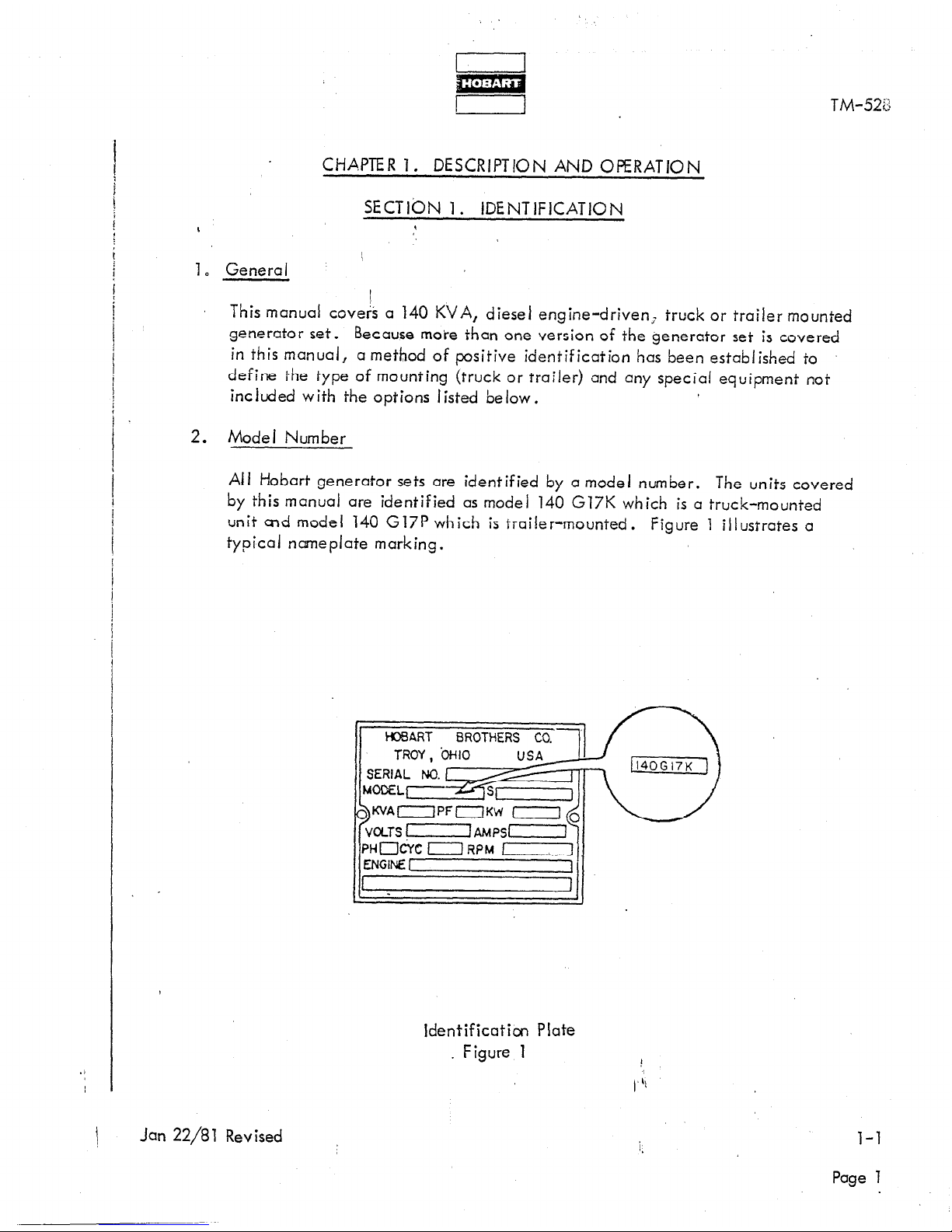
1. General
This manual coveA a 140 KVA, diesel engine-driven; truck or trailer mounted
generator set.
Because more than one version of the generator set is covered
in this manual, a method of positive identification has been established to
define the type of mounting (truck or trailer) and any special equipment not
included with the options I isted below.
2. Model Number
Ail Hobart generator sets are identified by a model number. The units covered
by this manual are identified as model 140 G17K which is a truck-mounted
unit end model 140 G17P which is trailer-mounted. Figure 1 illustrates a
typical nameplate marking.
1 WART BROTHERS CO. 1
If-Y
K’JAOPFOKW
Identification Plate
. Figure 1
\
Jan 22/81 Revised
Page 1
TM-528
140G17K defines a generator set mounted on any of the truck options listed below.
140G17P defines a generator set mounted on the optional trailer.
140G17P (special) ‘defines a trailer-mounted generator set which includes special equipment.
3. Optional Eqbi,pment
Optional equipment consists of trucks,
transformer-rectifier mounting kitk, a revolving amber light and a test box.
/
A. Trucks
The truck options consist of Chevrolet model CS-51403, Ford model F-500, GMC
model CS-51403 and Dodge model D-500.
B. Truck Body Kits
Truck body kits, part number 482150, are available for mounting the basic generator
set, with or without transformer-rectifiers, on any of the available truck options. These
kits are described and illustrated in TO-110.
I
C. Trailer
I
The optional trailer, part number 482158,
TO-106.
,
truck body kits, trailer, transformer-rectifiers,
is covered by an instruction manual
D. Transformer-Rectifiers
Transfomler-rectifiers are available to change the 115-V AC generator output to 28.5,
35 and 112 V DC. The 28.5 volt unit is covered in TM-597, the 112 volt unit is covered
in TM-598 and the 35 vo It unit is covered in TM-599.
E. T-R Mounting Kits
Transformer-rectifier mounting kits, part number 482163, are available for mounting
any combination of T-R units on the optional trucks at-d trailer. These kits are covered
in TO-111.
F. Test Box
The optional test box, part number 388318-4, is available to check voltage levels at
critical points throughout the circuitry.
It plugs into the test receptacle connector
on the engine control panel of each unit. This option is covered in TO-112.
Page 2
\;
Revised Jan 22/81
I
I
TM-528
G. Revo iving Light (Truck-Mounted Units)
This emergency warning iigbt revolves through 3600. Central iy mounted on top
of the truck cab, it has an ‘on-off switch located on the dashboard. This option
is covered in TO-1 13.
1
Jan 22/81 Revised ;
i.
l-l
Page 3/4

!d
r I
SECT1 ON 2. DESCRIPTION
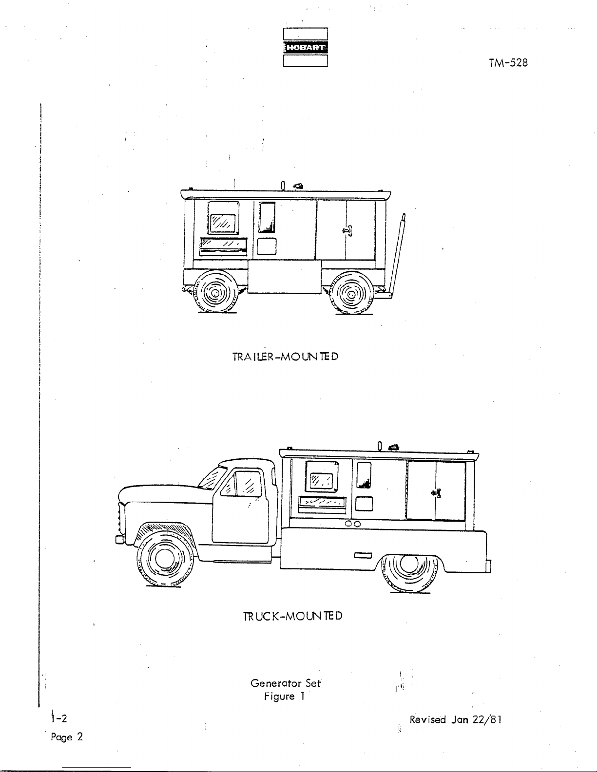
1. General
The generator set covered by this manual is a diesel engine-driven unit,
enclosed by a canopy and designed for mounting on a truck or trailer
(See Fig. 1). ’
TM-528
/
The purpose of the generator set is to produce and deliver regulated, 400-Hz,
115/200-V AC power to one o,r two parked aircraft for operation of the air-
craft’s electrical equipment when the on-board generators are not running.
Orientation
2.
For purposes of orientat ion and to fcm ii iarize operators and maintenance
personnel with the location of components, the radiator is considered to
be at the FRONT of the unit. The generator and controls are at the REAR.
RIGHT and LEFT are determined by standing at the rear and facing the
math ine .
and engine control panel are mounted on the RIGHT side at the REAR of
the unit.
NOTE: When the generator set is mounted on a truck, the rcdictor or
FRONT end of the generator set is at the REAR of the truck.
Operating controls are then on the LEFT, or driver’s side, of
the truck. When the generator set is mounted on a trailer,
the radiator is at the drawbar, FRONT end.
3. Special Features
Thus, the generator control box, output receptacle connector,
The generator has many special features which are described more fully
under the assemblies in which they appear. Some of the main features
are mentioned here and described briefly.
A. Protective Monitor System
A single, solid-state device (1, Fig.
the fault sensing units in the generator output circuit and functions
to cause the load to be disconnected from the generator if an abnormal
condition of voltage,
Pullout Trays
B.
The control box is equipped with pullout, drawer-type trays which
provide easy access to controls and equipment md,unted in them.
Each tray may be removed as an assembly by disbbnnecting a single
quick-disconnect connector and tripping two safety latches.
Jan 22/81 Revised :
7) receives signals from ail of
frequency or load develops.
1,
l-2
Page 1
/
I
m
I 1
TM-528
TRAILER-MOLNTED
TRUCK-MOUNTED
Generator Set
Figure 1
f-2
Page 2
i Revised Jan 22/81
TM-528
C. Voltage Regulator
I
A solid-state, adiustabie voltage regulator (Fig. 6) provides automatic
voltage regulation at f’he aircraft.
The regulator is also adiustabie for
a variety of output cable sizes and lengths.
D. Test Receptacle Connector
A receptacle connector (18, Fig. 9 and 10) with wiring ta various test
points throughout the eiectricai circuit is provided for the attachment
of a test box. This circuitry, when used in conjunction with diagrams,
allows technicians to monitor voltage levels at critical points throughout
the circuitry.
E.
Test bx
The optional test box may be plugged into the test receptacle connector
and used to check voltage levels at critical points throughout the circuitry.
F.
D.uai Output
Each generator set is equipped with two output circuits and dual controls
so that power may be delivered to an aircraft requiring two inputs, or to
one or two aircraft with single input requirements.
4. Canopy
A sheet metal enclosure,
identified as a canopy (See 1, Fig. 2) provides
protection for the engine, generator, and electrical controls. Four hinged
doors on the left side provide easy access for service and maintenance. Two
hinged doors near the front on the right side provide access to the engine
corn partme nt .
Panel mounted instruments may be observed through two Plexiglass
windows which cover a portion of the control box and engine control panel.
The lower window is slanted outward at the bottom to provide an opening for
reaching engine controls.
A small panel located below the air cleaner covers
the dual-output terminal board.
Two cable horns and clamps provide protection
and security for output cables.
A central iy-located lifting eye is mounted in
the main frcrne superstructure and extends upward beyond the canopy top to
provide a convenient attaching point for chains, cables, hooks, etc., used
to I ift and move the generator set.
Jan 22/81 Revised
:
i;
l-2
Page 3
m
I 1
TM-528
L
I
5. Engine, Generator and Controls Assembly.
A. General
This assembly is the basic generator set without canopy.
It includes all
components required to igenerate and reg’ulate 400-iiz, 115/200-V AC,
three-phase power,
and is operable when provided with a system to supply
fuel to the engine fuel plump.
Four six-volt batteries mounted in the optional
/
trailer or truck body, are connected in series to provide 24-V DC power to
the engine direct current circuits:
A tcp lecd connected In this circuit
between the two center batteries provides 12-V DC power for the generator
protective system.
The engine-generator assembly is mounted on a welded
stee I f rme .
A superstructure,
attached to the main frame, provides mounting facilities
for the canopy, control box,
and m isceiianeous electrical equipment.
Specifications and capabilities of the’generator set are listed in Figure 3.
8.
Gene rato r
The generator (11, Fig. 2) is a brushless, revolving field, three-phase,
alternating-current type.
It is technically an alternator, however it will
be identified throughout the manual as a generator. The rotor is mounted
by two permanently lubricated, sealed, bail bearings. The front bearing
is supported by the fan housing; the rear bearing is mounted in the forward
end of the exciter housing.
Both of these housings are attached to the main
generator stator housing.
The front end of the rotor shaft extends forward
beyond the bearing and is. attached to the engine flywheel by a hub and
flexible disk coupling assembly.
A centrifugal, radial-blade fan, part
of the hub and coupling assembly, draws cooling air over ail internal
windings.
Air enters the exciter end and is discharged through openings
in the flywheel housing at the drive end. The rear end of the rotor shaft
extends rearward beyond the rear bearing and into the exciter stator housing.
The exciter rotor is mounted on this shaft extension with a Woodruff key and
is secured by a washer and cap screw.
A rectifier with six diodes is mounted
on the exciter rotor and converts exciter AC output to DC for excitation
of the generator revolving fields.
The exciter output to the generator
fields, and consequently the generator output, is controlled by the amount
of DC voltage supplied to exciter fields by the static voltage regulator.
C. Engine
The engine (7, Fig. 2) used to drive the generator is a two-cycle, Vee-8
diesel, manufactured by Detroit Diesel Engine Division af General Motors
Corporation. See Fig.
3 for specifications and characterh’stics. Refer to
the Detroit Diesel Operator’s Manual for a detailed description. ’
112
Revised Jan 22/81
Page 4
f
n Ili=l n I 1
i i
I 1
u
r 1
TM-528
/
II
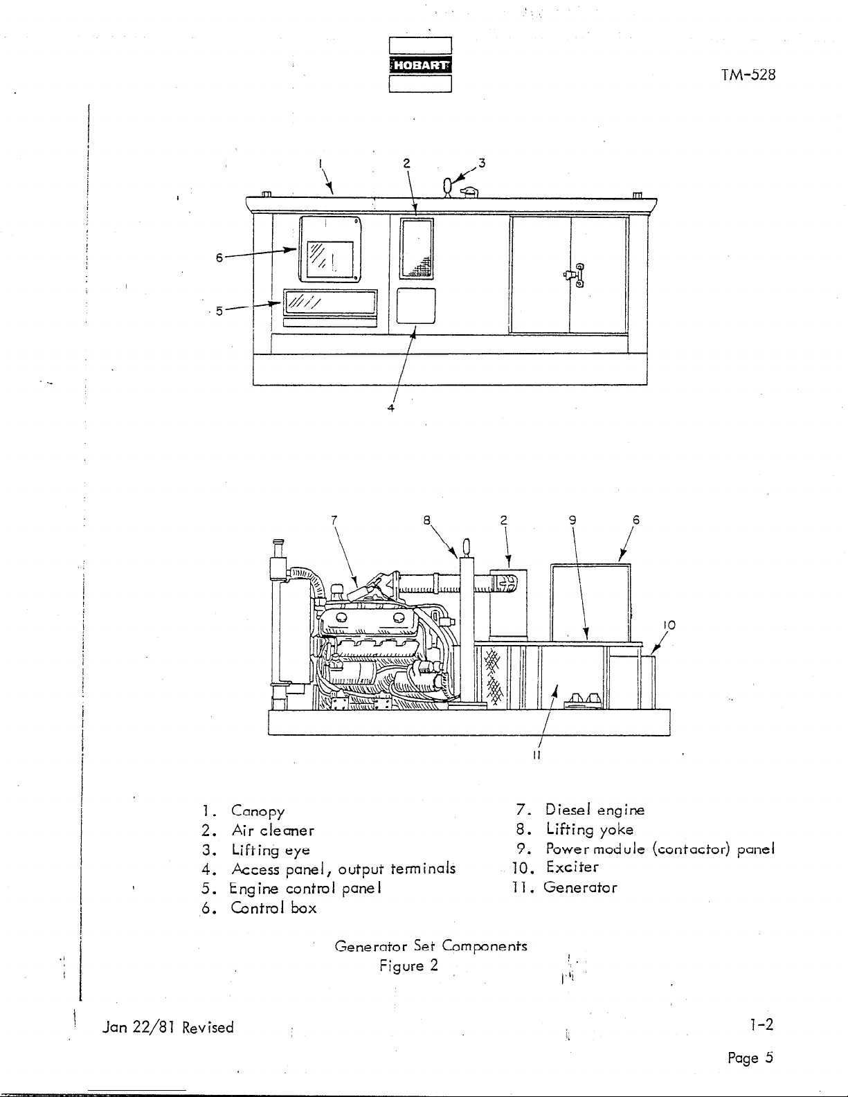
1. Canopy 7. Diesel engine
2. Air cleaner 8. Lifting yoke
3. Lifting eye
9. Power module (contactor) panei
4. Access panel, output terminals 10. Exciter
5. Engine control panel 11. Generator
6. Control box
Generator Set Components
Figure 2
1
.
(‘Ii
!
Jan 22/8 1 Revised
l-2
Page 5

GENERATOR
I I
TM-528
Output power rating
0 utput voltage
Rated lo&I capacity
Overload capacity (125% of lrated load) ’
Frequency (cycles-per-second)
0 utput ki iowatts
Po,wer factor
Duty cycle
Operating speed (at 400 Hz)
Output cable size (each of four conductors)
ENGINE
Manufacturer
,
I
,.
Detroit Diesel Engine Div.
140 KVA
115/200-v
404-A
505-A
400 Hz
172 KW
0.8 PF
100%
T7P4 RPM
210
General Motors Corp.
Type
Model
Displacement
Bore and stroke
Governed speed
Horsepower at 1714 RPM
Id!e speed
Overspeed governor trip
Coolant system capacity (approx.)
Lubricating oil capacity (without filters change) (approx.) 23 quarts (21 liters)
Lubricating oil capacity (with filters change) (approx.) 26 quarts (25 liters)
567 cubic inches (9291 c.m3)
4-l/2 x 5 inches (115 mmx 127 mm)
1900 to 2025 RPM
19-l/2 gals. (74 liters)
8V-77 N diesel
7083-7000
1714 RPM
253 HP
800 to 850 RPM
D. Governor
The mechanical-hydraulic governor (4, Fig. 4) is identified as a Woodward
Model PSG. Instructions and an ii iustrated parts list for the governor are
included in Woodward Bulletin which is supplied with this manual in Chapter 6.
Engine Safety Shutdown System
E.’
(1) General
The automatic, electric, shutdown system is designed to stop t& engine if there is a loss of oil
pressure, overheating of engine coolant, or engine overspeed.
Page 6
Specifications and Capabilities
Figure 3
 Loading...