

Page 1
OM-2228
10/15/13- Rev A
U.S.A.
05/06/13– Original
Operation and Maintenance Manual
with
Illustrated Parts List
for
120CU20
120 kVA, 3 Phase, 115/200 V ol t,
400 Hz. Generator Set
Series 500120
ITW GSE Group
Hobart Ground Systems
Palmetto, Florida 34221
Page 2

.
Page 3

Warranty
U.S.A.
Data Sheet 165
Index: 990223
QUALIFIED PERSO NNEL SHOULD ALWAYS BE EMPLOYED FOR SUC H T AS KS.
HOBART GROUND SYSTEMS
PALMETTO, FLORIDA 34221
1. Hobart Brothers Company (hereinafter called HOBART) warrants that each new and unused Hobart Ground Power
Equipment, (hereinafter called the PRODUCT) is of good workmanship and is free from mechanical defects,
provided that (1) the PRODUCT is installed and operated in accordance with the printed instructions of HOBART,
(2) the PRODUCT is used under the normal operating conditions for which it is designed, (3) the PRODUCT i s not
subjected to misuse, negligence or accident, and (4) the PRODUCT receives proper care, lubrication, protection,
and mainte nance under the supervis ion of trained personnel .
2. This warranty expires 15 months aft er shipment by HOBART to the first user, or 12 months after installation,
whichever first occurs.
3. This warranty does not apply to: primary and secondary switch contacts, cable connectors, carbon brushes, fuses,
bulbs, and filters unless found to be defective prior to use.
4. Hobart DOES NOT WARRANT THE FOLLOWING COMPONENTS: Engines, engine components; such as:
starters, alternators, regulators, governors, etc., and cable retrieving devices. Many of the foregoing components
are warranted directly by the manufacturer to the first user and serviced by a worldwide network of distributors and
others authorized to handle claims for component manufacturers. A first user’s claim should be presented directly
to such an authorized component service outlet. In the event any component manufacturer has warranted its
component to HOBART and will not dea l directly with a first user then HOBART will cooperate with the first user
in the presentation of a claim to such manufacturer. Under NO circumstances does HOBART assume any liability
for any warranty claim against or warranty work done by or in behalf of any manufacturer of the foregoing
components.
5. This warranty is extend ed by HOBART only to the purchaser of new PRODUCTS from HOBART o r one of its
authorized distributors. The P ROD UCTS purchased under this warranty are intended for use exclusively by the
buyer and his employees and by no other persons and, therefore, there shall be no third party beneficiary to this
warranty.
6. A claim of defects in any PRODUCT covered by this warranty is subject to HOBART factory inspection and
judgment. HOBART’S liability is limited to repair of any defects fou nd by HOBART to exist, or at HOBART’S
option the replacement of the defective product, F.O.B. factory, after the defective product has been returned by the
purchaser at its expense to HOBART’S shipping place. Replacement and exchange parts will be warranted for the
remainder of the original Warranty, or for a period of ninety (90) days, whichever is greater.
7. UNDER NO CIRCUMSTANCES whatsoever shall HOBART and its a uthorized distributors be liable for a ny
special or consequential damages, whether based on lost goodwill, lost resale profits, work stoppage impairment
of other goods or otherwise, and whether arising out of breach of any express or implied warranty, breach of
contract, negligence or otherwise, except only in the case of personal injury as may be required by applicable law.
8. Continued use of the PRODUCT(S) after discovery of a defect VOIDS ALL WARRANTIES.
9. Except as authorized in writing, this warranty does not cover any equipment that has been altered by any party
other than H OBART.
10. THERE ARE NO WARRANTIES WHICH EXTEND BEYOND THE DESCRIPTION ON THE FACE HERE
OF. HOBART MAKES NO WARRANTIES, EXPRESSED OR IMPLIED, OF MERCHANT ABILITY OR
FITNESS FOR A PARTICULAR PURPOSE.
11. HOBART neither assumes nor authorizes any person to assume for HOBART any liability in connection with the
PRODUCTS sold, and there are no oral agreements or warranties collateral to or affecting this written Warranty.
This warranty and all undertakings of HOBART there under shall be governed by the laws of the State of Florida,
United States of America.
Replaces: 980601
WARNING AT ALL TIMES, SAFETY MUST BE CONSIDERED AN IMPORTANT FACTOR IN THE
INSTALLATION, SERVICING AND OPERATION OF THE PRODUCT, AND SKILLED, TECHNICALLY
Page 4

.
Page 5

OM-2228 / Operation and Maintenance Manual
120CU20 / Series 500120 / 400 Hz. Generator Set
October 15, 2013
Revision Log
Page 1
Record of Change.
Rev.
No.
Release Date.
By
Description.
0
May 06, 2013
HLC
1. New – spec roll for new starter, wire harness, etc. to create
Deluxe and Standard models.
A
October 15, 2013
H A
Created Revision Log. Changed Insulation to show that it is now an
reflect that the unit is now made in Florida.
option, removed composite fuel tank and updated the manual to
Page 6

OM-2228 / Operation and Maintenance Manual
120CU20 / Series 500120 / 400 Hz. Generator Set
October 15, 2013
Revision Log
Page 2
This page is intentionally left blank.
.
Page 7

OM-2228 / Operation and Maintenance Manual
120CU20 / Series 500120 / 400 Hz. Generator Set
October 15, 2013
Safety War nings
Page 1
Safety Warnings and
Cautions.
ELECTRIC SHOCK
KILL
attached equipment.
WARNING
IMPORTANT
WARNING
ELECTRIC ARC FLASH can injure eyes, burn skin, cause equipment damage, and
ignite combustible material. DO NOT use power cables to break load and prevent tools
from causing short circuits.
IMPROPER PHASE CONNECTION, PARALLELING, OR USE can damage this and
Protect all operating personnel. Read, understand, and follow all instructions in the
Operating/Instruction Manual before installing, operating, or servicing the equipment.
Keep the manual available for future use by all operators.
CALIFORNIA PROPOSITION 65 - DIESEL ENGINES. Diesel engine exhaust and
some of its constituents are known to the State of California to cause cancer, birth
defects and other reproductive harm.
can
. Do not touch live electrical parts.
1) General.
Equipment that supplies electrical power can cause serious injury or death, or damage to other equipment or
property. The operator must strictly observe all safety rules and take precautionary actions. Safe practices
have been developed from experience in the use of power source equipment. While certain practices below
apply only to electrically powered equipment, other practices apply to engine-driven equipment, and some
practices to both.
2) Shock Prevention.
Bare conductors, terminals in the output circuit, or ungrounded, electrically live equipment can fatally shock a
person. Have a certified electrician verify that the equipment is adequately grounded and learn what
terminals and parts are electrically HOT. Avoid hot spots on machine. Use proper safety clothing, procedures,
and test equipment.
The electrical resistance of the body is decreased when wet, permitting dangerous currents to flow through it.
When inspecting or servicing equipment, do not work in damp areas. Stand on a dry rubber mat or dry wood,
and use insulating gloves when dampness or sweat cannot be avoided. Keep clothing dry, and never work
alone.
a) Installation and Grounding of Electrically Powered Equipment
Equipment driven by electric motors (rather than by diesel or gasoline engines) must be installed and
maintained in accordance with the National Electrical Code, ANSI/NFPA 70, or other applicable
codes. A power disconnect switch or circuit breaker must be located at the equipment. Check the
nameplate for voltage, frequency, and phase requirements. If only 3-phase power is available,
connect any single-p has e rated equ ipment to only two wires of the 3-phase line. DO NOT CONNECT
Page 8

OM-2228 / Operation and Maintenance Manual
120CU20 / Series 500120 / 400 Hz. Generator Set
October 15, 2013
Safety War nings
Page 2
the equipment grounding conductor (lead) to the third live wire of the 3-phase line, as this makes the
equipment frame electrically HOT, which can cause a fatal shock.
Always connect the grounding lead, if supplied in a power line cable, to the grounded switch box or
building ground. If not provided, use a separate grounding lead. Ensure that the current (amperage)
capacity of the grounding lead will be adequate for the worst fault current situation. Refer to the
National Electrical Code ANSI/NFPA 70 for details. Do not remove plug ground prongs. Use correctly
mating receptacles.
b) Output Cables and Terminals.
Inspect cables frequently for damage to the insulation and the connectors. Replace or repair cracked
or worn cables immediately. Do not overload cables. Do not touch output terminal while equipment is
energized.
3) Service and Maintenance.
This equipment must be maintained in good electrical condition to avoid hazards stemming from
disrepair. Report any equipment defect or safety hazard to the supervisor and discontinue use of the
equipment until its safety has been assured. Repairs should be made by qualified personnel only. Before
inspecting or servicing this equipment, take the following precautions:
a) Shut off all power at the disconnecting switch, or line breaker, or by disconnecting battery, before
inspecting or servicing the equipment.
b) Lock switch OPEN (or remove line fuses) so that power cannot be turned on accidentally.
c) Disconnect power to equipment if it is out of service.
d) If troubleshooting must be done with the unit energized, have another person present who is trained
in turning off the equipment and providing or calling for first aid.
4) Fire And Explosion Prevention.
Fire and explosion are caused by electrical short circuits, combustible material near engine exhaust
pipes, misuse of batteries and fuel, or unsafe operating or fueling conditions.
a) El ectrical Short Circuits and Overloads.
Overloaded or shorted equipment can become hot enough to cause fires by self-destruction or by
causing nearby combustibles to ignite. For electrically powered equipment, provide primary input
protection to remove short circuited or heavily overloaded equipment from the line.
b) Batteries.
Batteries may explode and/or give off flammable hydrogen gas. Acid and arcing from a ruptured
battery can cause fires and additional failures. When servicing, do not smoke, cause sparking, or use
open flame near the battery.
c) Engine Fuel.
Use only approved fuel container or fueling system. Fires and explosions can occur if the fuel tank is
not grounded prior to or during fuel transfer. Shut unit DOWN before opening fuel tank cap. DO NOT
Page 9

OM-2228 / Operation and Maintenance Manual
120CU20 / Series 500120 / 400 Hz. Generator Set
October 15, 2013
Safety War nings
Page 3
EMERGENCY
FIRST AID
completely fill tank, because heat from the equipment may cause fuel expansion overflow. Remove
all spilled fuel IMMEDIATELY, including any that penetrates the unit. After clean-up, open equipment
doors and blow fumes away with compressed air.
5) Toxic Fume Prevention.
Carbon monoxide - Engine exhaust fumes can kill and cause health problems. Pipe or vent the exhaust
fumes to a suitable exhaust duct or outdoors. Never locate engine exhausts near intake ducts of air
conditioners.
6) Bodily Injury Prevention.
Serious injury can result from contact with fans or hot spots inside some equipment. Shut DOWN such
equipment for inspection and routine maintenance. When equipment is in operation, use extreme care in
doing necessary trouble-shooting and adjustment. Do not remove guards while equipment is operating.
7) Medical and First Aid Treatment.
First aid facilities and a qualified first aid person should be available for each shift for immediate treatment
of all injury victims. Electric shock victims should be checked by a physician and taken to a hospital
immediately if any abnormal signs are observed.
Call physician immediately. Seek additional assistance. Use First Aid techniques
recommended by American Red Cross until medical help arrives.
IF BREATHING IS DIFFICULT, give oxygen, if available, and have victim lie down.
FOR ELECTRICAL SHOCK, turn off power. Remove victim; if not breathing, begin
artificial respiration, preferably mouth-to-mouth. If no detectable pulse, begin external
heart massage. CALL EMERGENCY RESCUE SQUAD IMMEDIATELY.
8) Equipment Precautionary Labels.
Inspect all precautionary labels on the equipment monthly. Order and replace all labels that cannot be
easily read.
Page 10

OM-2228 / Operation and Maintenance Manual
120CU20 / Series 500120 / 400 Hz. Generator Set
October 15, 2013
Safety War nings
Page 4
This page is intentionally left blank.
Page 11

OM-2228 / Operation and Maintenance Manual
120CU20 / Series 500120 / 400 Hz. Generator Set
October 15, 2013
Introduction
Page 1
Introduction
This manual contains operation and maintenance information for a 120CU20, 400 Hz Generator Set
manufactured by ITW GSE Group, Hobart Ground Systems, Palmetto, Florida 34221.
This manual is not intended to be a textbook on electricity or electronics. Its primary purpose is to provide
information and instructions to experienced operators, electricians, and mechanics who have never operated
this equipment. It is the intent of this manual to guide and assist operators and maintenance people in the
proper use and care of the equipment.
Use of the manual should not be put off until a trouble or need for help develops. Read the instructions
before starting the unit. Learn to use the manual and to locate information contained in it. Its style and
arrangement are very similar to commercial aircraft manuals.
The manual is divided into five chapters plus an appendix. Each chapter is divided into as many sections as
required. Each new section starts with page 1. Each page is identified by chapter, section and page number,
which are located in the lower, outside corner. When information located in another portion of the manual is
referred to, its location is identified by a chapter, section, and paragraph or figure number.
For example: “(see Section 2-3, Paragraph 1.a.)” refers to information located in Chapter 2, Section 3,
Paragraph 1.a. If a chapter and section are not indicated in a reference, the referenced material is located in
the same section as the reference, for example: “(see Paragraph 1.a.).”
The Appendix is the last section. It contains a list of available options that may be purchased with that unit.
Items on the list with check marks next to them, have been added to the standard unit per the customers
order. Literature for each option follows. The Appendix will help control the information in the manual:
making it unique to the unit purchased.
In addition to operation and maintenance instructions, the manual contains an illustrated parts list in Chapter
4, and a collection of manufacturer’s literature and supplemental information in Chapter 5.
The manual is arranged as follows:
Chapter 1: Description/Operation
Chapter 2: Servicing/Troubleshooting
Chapter 3: Overhaul/Major Repair
Chapter 4: Illustrated Parts List
Chapter 5: Manufacturer’s Literature
Appendix A: Options
Page 12

OM-2228 / Operation and Maintenance Manual
120CU20 / Series 500120 / 400 Hz. Generator Set
October 15, 2013
Introduction
Page 2
If you have any questions concerning your Hobart Ground Systems equipment, immediately contact our
Service Department by mail, telephone, FAX, or E-Mail.
Write: Hobart Ground Systems
Service Department
11001 US Highway 41, North
Palmetto, FL 34221
U.S.A.
Call Inside U.S.A.: (800) 422-4166 (Parts)
(877) 874-5322 (Customer Service)
Call From Foreign Countries: (941) 721-1000 (Parts)
(941) 721-1092 (Service/ Technical Support)
FAX Inside U.S.A. (941) 723-3160
FAX From Foreign Countries: (941) 721-1087
E-mail :
service@hobartsystems.com
Web Page :
www.hobartsystems.com
Page 13

OM-2228/ Operation and Maintenance Manual
120CU20 / Series 500120 / 400 Hz. Generator Set
October 15, 2013
Table of Contents
Page 1
Chapter 1
Description/Operation.
Chapter-Section/Page#
Section 1
Description.
1-1/1
General
1-1/1
Optional Equipment - Appendix A
1-1/1
Orientation
1-1/1
Special Features
1-1/2
Canopy
1-1/2
Specifications
1-1/3
Engine and Generator
1-1/5
Control Box Assembly
1-1/11
Power Module Panel Assembly
1-1/22
Cold Weather Start System
1-1/24
Transformer-Rectifier Assembly Components
1-1/25
Section 2
Preparation for Use, Storage or Shi p p ing.
1-2/1
Preparation For Use
1-2/1
Preparation for Storage
1-2/5
Preparation for Shipment
1-2/6
Section 3
Operation.
1-3/1
General
1-3/1
400 Hz. Operation Procedure
1-3/1
DC Operation Procedure
1-3/6
Simultaneous AC and DC Operation
1-3/6
Chapter 2
Servicing / Troubleshooting.
Chapter-Section/Page#
Section 1
Maintenance Inspection/Check.
2-1/1
General.
2-1/1
Maintenance Schedule.
2-1/1
Inspection / Check.
2-1/3
Table of Contents.
Page 14

OM-2228/ Operation and Maintenance Manual
120CU20 / Series 500120 / 400 Hz. Generator Set
October 15, 2013
Table of Contents
Page 2
Section 2
Maintenance Procedures.
2-2/1
General
2-2/1
Servicing The Air Cleaner
2-2/6
Engine Fuel
2-2/7
Engine Cooling System
2-2/10
Generator Maintenance
2-2/14
Section 3
Adjustments / Tests.
2-3/1
Testing the 400 Hz. Generator Set
2-3/1
Generator Set Adjustments
2-3/12
Diode Test
2-3/16
Testing the Transformer-Rectifier
2-3/16
Section 4
Troubleshooting Procedures.
2-4/1
Equipment for Troubleshooting
2-4/1
Parts Replacement
2-4/1
Check Connections and Leads
2-4/2
Engine Troubleshooting
2-4/2
Connection and Schematic Diagr ams
2-4/2
GPU Control Monitoring
2-4/3
…Engine Controls
2-4/10
…Generator Excitation Circuits
2-4/13
…Protective Circuit
2-4/16
…Generator
2-4/18
Troubleshooting Tables – GPU Commands
2-4/21
Troubleshooting Tables – GPU Faults
2-4/22
Lubrication
Engine Fuel System
Drive Belt
General
Generator and Exciter Test
Adjusting the Transformer-Rectifier
General
2-2/1
2-2/7
2-2/14
2-3/1
2-3/15
2-3/18
2-4/1
400 Hz. Test Values
Illustrations
2-4/2
2-4/2
Troubleshooting Charts. 2-4/10
…Load Contactor Operating Circuits
…T-R Controls and Components
2-4/14
2-4/19
Page 15

OM-2228/ Operation and Maintenance Manual
120CU20 / Series 500120 / 400 Hz. Generator Set
October 15, 2013
Table of Contents
Page 3
Chapter 3
Overhaul / Major Repair.
Chapter-Section/Page#
Section 1
Exciter Armature.
3-1/1
General
3-1/1
Exciter Armature
3-1/2
Exciter Armature Replacement
3-1/3
Exciter Armature Installation
3-1/6
Section 2
Dual Bearing Flexible Coupling.
3-2/1
General
3-2/1
Disassembly
3-2/1
Coupling Service
3-2/4
Coupling Installation
3-2/5
Reassemble Engine and Generator
3-2/6
Run-in and Periodic Check
3-2/7
Section 3
Generator Assembly.
3-3/1
General
3-3/1
Generator Assembly Removal
3-3/1
Generator Assembly Installation
3-3/4
Chapter 4
Illustrated Parts List .
Chapter-Section/Page#
Section 1
Introduction.
4-1/1
General
4-1/1
Purpose
4-1/1
Arrangement
4-1/1
Explanation of Parts List
4-1/1
Section 2
Manufacture's Codes.
4-2/1
Explanation of Manufacture's (Vendor) Code List
4-2/1
Page 16

OM-2228/ Operation and Maintenance Manual
120CU20 / Series 500120 / 400 Hz. Generator Set
October 15, 2013
Table of Contents
Page 4
Section 3
Illustrated Parts List.
4-3/1
Explanation of Parts List Arrangement
4-3/1
Figure 1: General Assembly
4-3/2
Figure 2: Labels and Reflectors
4-3/4
Figure 4: Canopy Assembly
4-3/7
Figure 5: Canopy Doors
4-3/10
Figure 7: Control Box Door Panel Assembly
4-3/14
Figure 8: Control Box Interior Components
4-3/16
Figure 10: 400 Hz. Power Module Assembly
4-3/20
Figure 11: Cooling System Compone nts
4-3/22
Figure 13: Fuel System Components
4-3/26
Figure 14: Engine Exhaust Compone nts
4-3/28
Figure 16: Air Cleaner Components
4-3/32
Figure 17: Engine Components
4-3/34
Figure 19: Generator Assembly
4-3/38
Figure 20: Transformer-Rectifier Assembly (DC Option)
4-3/40
Figure 22: T-R Interlock Kit (DC Option Acc es sor y )
4-3/44
Section 4
Numerical Index.
4-4/1
Explanation of Numerical Index
4-4/1
Chapter 5
Manufacture's Literature.
Appendix A Options/Features.
Wet Stacking.
Unusual Service Conditions.
Symbols and Abbreviations
Figure 3: Frame Assembly
Figure 6: Internal Components
Figure 9: Pushbutton Switches
Figure 12: Engine Ground Plate and Cables
Figure 15: 12 VDC Battery System
Figure 18: Engine Electrical Panel Com pon ents
4-3/1
4-3/6
4-3/12
4-3/18
4-3/24
4-3/30
4-3/36
Figure 21: DC Output Contactor (DC Option)
4-3/42
Page 17
OM-2228 / Operation and Maintenance Manual
120CU20 / Series 500120 / 400 Hz. Generator Set
October 15, 2013
Chapter 1-1
Page 1
Chapter 1
Description/Operation.
Section 1
Description.
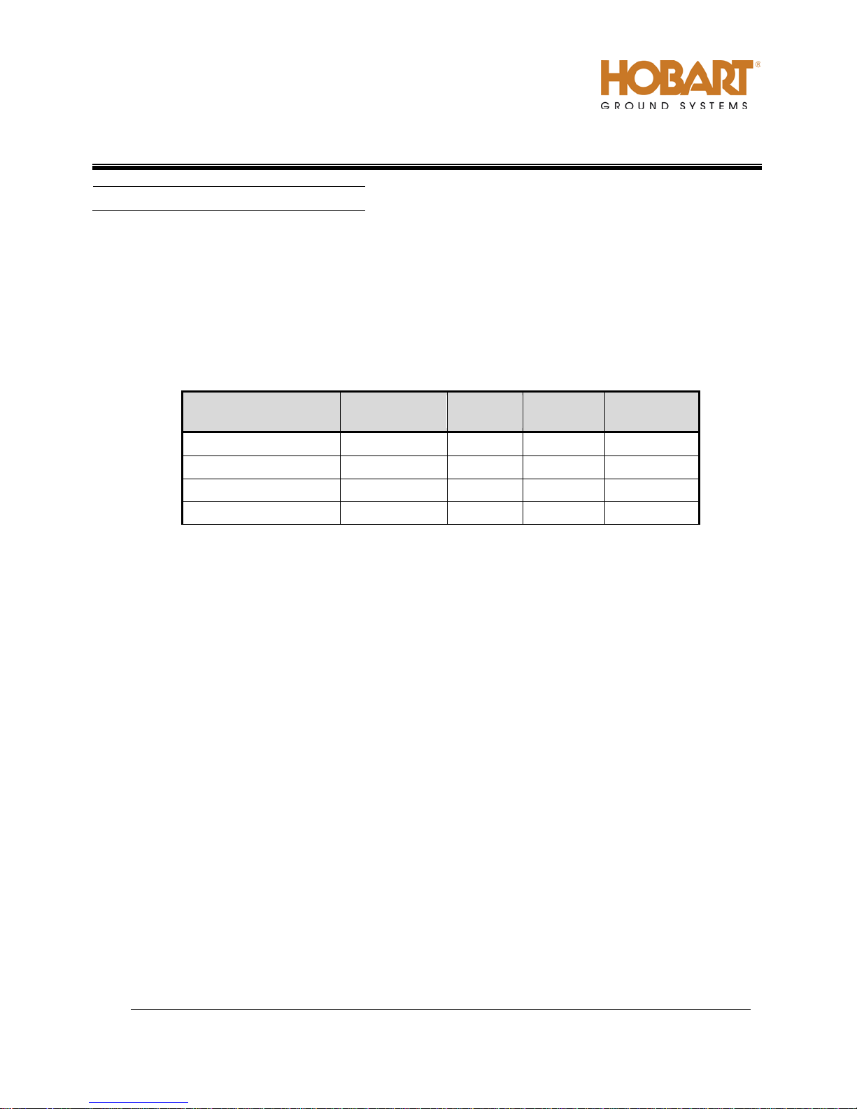
Part & Dash Number
AC
Outputs
28.5 VDC
Output
500120-STD
Trailer
2
--
Stainless
500120-DLX
Trailer
2
--
Stainless
500120TR-STD
Trailer
2
Yes
Stainless
500120TR-DLX
Trailer
2
Yes
Stainless
1) General.
The basic generator set covered in this manual, manufactured by ITW GSE Group, Hobart Ground
Systems is rated at 120 kVA and designed to produce and deliver 115/200-volt, 400 Hz, 3-phase AC
power to a parked aircraft or other load.
The number 500120 identifies the “model or series” of the GPU. The part number is followed by a
different dash number that separates the basic units available. Table 1 uses the part number to identify
the variations covered in this manual.
Mounting
Table 1: Series 500120 Generator Set Part Number Descriptions.
Fuel Tank
2) Optional Equipment - Appendix A.
Chapters 1 through 5 of this Operation and Maintenance Manual identifies only the “stripped down”
version of the 120CU20 generator set. A list of optional equipment that makes this manual uniqu e to the
generator set that you have purchased, appears in Appendix A.
The body of this manual includes documentation for the DC option, also known as the TransformerRectifier (T-R). Details for other options may be included in Appendix A.
3) Orientation.
For purpose of orientation, the radiator is considered to be at the REAR of the unit. The generator and
controls are at the FRONT. RIGHT and LEFT are determined by standing at the REAR end facing the
machine. Thus, the control box is mounted on the LEFT FRONT side of the unit.
Page 18

OM-2228 / Operation and Maintenance Manual
120CU20 / Series 500120 / 400 Hz. Generator Set
October 15, 2013
Chapter 1-1
Page 2
4) Special Features.
The generator set has special features that are described more fully, under the assemblies in which they
appear.
a) Protective Monitoring.
The protective monitoring system receives signals from the fault sensing units in the generator output
circuit and functions to cause the load to be disconnected from the generator if an abnormal condition
of voltage, frequency, or load develops.
b) Voltage Regulator.
A microprocessor-type, adjustable voltage regulator provides automatic voltage regulation at the
aircraft. The regulator is also adjustable for a variety of output cable sizes and lengths.
c) Engine Electronic Control Module.
The engine is equipped with an electronic control module that monitors, records, and controls engine
performance.
5) Canopy.
A sheet metal enclosure, identified as a canopy, provides protection for the engine, generator and
electrical controls. The canopy is designed to reduce the operational noise level in the immediate area of
the machine.
Page 19
OM-2228 / Operation and Maintenance Manual
120CU20 / Series 500120 / 400 Hz. Generator Set
October 15, 2013
Chapter 1-1
Page 3
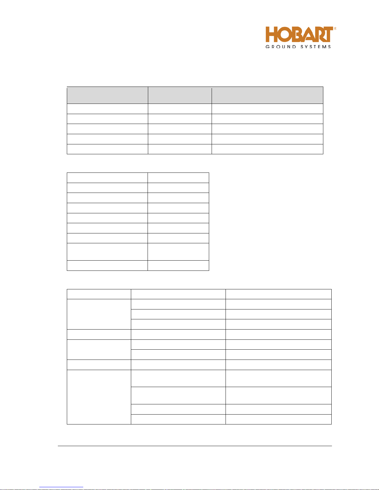
Basic Unit
(Fixed Mount)
Length
116 in. (2946 mm)
160 in. (4064 mm) w/ tow bar up
Width
59 in. (1499 mm)
77 in. (1956 mm)
Height
55 in. (1397 mm)
72 in. (1828 mm)
Weight (Full of Fuel)
5900 lb. (2676 kg.)
6500 lb. (2948 kg.)
Weight with 28.5 VDC T-R
6200 lb. (2812 kg.)
6800 lb. (3084 kg.)
Output power rating
120 kVA (96 kW)
Output voltage
115 / 200 VAC
Rated load capacity
348 Amps
Frequency
400 Hz.
Power factor
0.8
Duty Cycl e
100%
Operating speed
2000 RPM
outputs 125% rated load
Output cable size
2/0
Condition
Trip Point
Time Delay
Over voltage
126 volts
1-second
140 volts
160 milliseconds
180 volts
50 milliseconds
Under voltage
any voltage below 100 volts
7 seconds
Over frequency
420 Hz to 480 Hz
5 seconds
above 480 Hz
immediate
Under frequency
380 Hz. or less
7-seconds
Output overload
125% load of 90 kVA
on either output or
approximately 5 minutes
125% load of 120 kVA
on both outputs combined
approximately 5 minutes
150% load
30 seconds
200% load
10 seconds
6) Specifications
a) Physical Specifications
Physical
b) AC Generator Specifications
Overload capacity, both
With Trailer
435 Amps
c) AC Generator Protective System Specifications
Page 20
OM-2228 / Operation and Maintenance Manual
120CU20 / Series 500120 / 400 Hz. Generator Set
October 15, 2013
Chapter 1-1
Page 4
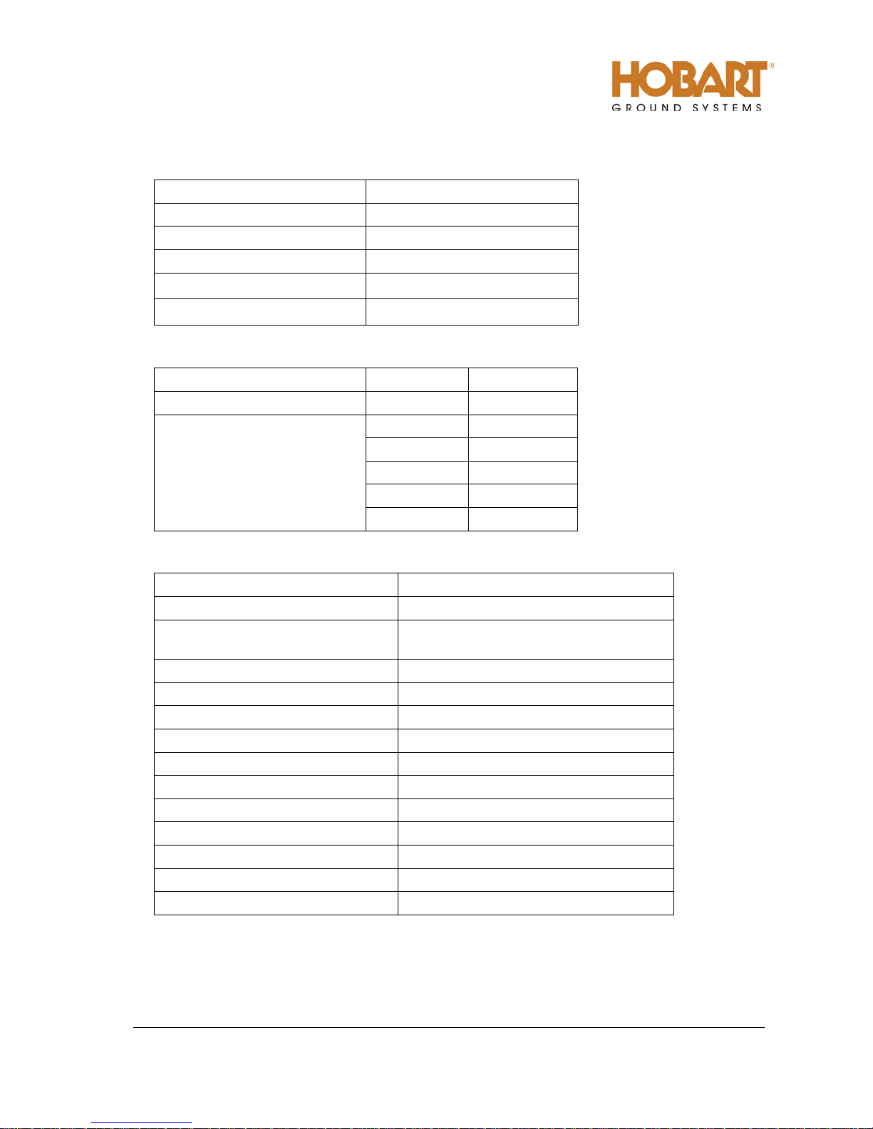
Output Power Rating
17.1 kW
Output Voltage
28.5 VDC
Load Capacity (Continuous)
600 A
Current Limiting Capability
100 to 2500 A
Condition
Trip Point
Time Delay
Over Voltage
32-34 VDC
2 seconds
2700 A
2 seconds
2000 A
10 seconds
1500 A
30 seconds
1200 A
90 seconds
750 A
600 seconds
Manufacturer
Cummins Engine Company
Model No.
QSB6.7
6 cylinder, 4 cycle diesel, electronic
controlled
Bore and Stroke
4.21 in. x 4.88 in. (107 mm x 124 mm)
Displacement
409 in3 (6.7 L)
Horsepower
220 hp (164 kW)
Idle speed
1000 ± 50 rpm
High speed limiting
2350 ± 75 rpm
Normal governed speed
2000 rpm
Firing Order
1-5-3-6-2-4
Electrical system
12 VDC
Ground
Negative
Lubricating oil capacity (w/ filter)
16 quarts (15.1 liters)
Coolant capacity system
40 quarts (37.8 liters)
d) DC Output Specifications (with optional TR unit).
Peak/Starting Load Capacity 2000 A for 10 seconds
Output cable size 4/0
e) DC Protective System Specifications.
Output Overload
f) Engine Specifications.
Type
Page 21

OM-2228 / Operation and Maintenance Manual
120CU20 / Series 500120 / 400 Hz. Generator Set
October 15, 2013
Chapter 1-1
Page 5
Engine coolant temperature
(normal operation)
g) Normal Operating Characteristics.
Engine oil pressure (warm and at
rated speed 2000 RPM)
45 PSI (310 kPa) minimum
50 to 65 PSI (345 to 448 kPA) typical
180 to 200º F (82 to 93º C)
7) Engine and Generator.
The engine and generator comprise the principal components of the generator set. They are mounted on
the welded steel frame of the chassis. The engine coolant radiator is also mounted on the frame just
forward of the engine-generator combination. Figures 2 and 3 are illustrations showing the location of all
major components and sub-assemblies.
a) Basic Engine.
The basic diesel engine is a fuel injection, 6-cylinder, electronically controlled engine rated at 220
horsepower.
b) Engine Manufacturer’s Equipment.
As received from the engine manufacturer, the engine includes the following equipment, which is
more fully described in the engine manufacturer’s operation manual.
(1) Elec trical System.
The 12 VDC electrical generating and starting system includes an alternator, voltage regulator,
and starter with solenoid switch.
(2) Lubricity Additive Fuel Filter.
The fuel filter is a spin-on disposable type, located on the interior bulkhead located in the middle
of the unit, on the left-hand side. The fuel filter primary function, other than remove contaminants
from the fuel, is to automatically add a lubricity additive to the fuel. Although, the engine
manufacturer does not recommend low lubricity fuels, this additive can extends the life of the fuel
pump.
CAUTION
(3) Oil Filter.
The engine oil filter is a spin-on, full-flow type, located on the left side of the engine near the front.
(4) Pre-programmed Electronic Control Module (ECM)
The ECM is a pre-programmed engine control module, mounted directly to the engine block.
The use of low lubricity fuels can shorten life and/or damage the engine’s fuel pump.
Only diesel fuel is recommended by the engine manufacturer.
Page 22

OM-2228 / Operation and Maintenance Manual
120CU20 / Series 500120 / 400 Hz. Generator Set
October 15, 2013
Chapter 1-1
Page 6
c) Engine-cooling fan
The engine fan is designed to blow air outward through the radiator, rather than pulling the air inward
as a conventional fan does.
d) Factory Installed Equipment
This generator set is modified at the factory by the addition of the following equipment:
(1) Shut Down/Reset device
In addition to the other devices provided by the engine manufacturer, the factory also added an
engine shutdown/reset feature.
a EMERGENCY SHUTDOWN/RESET SWITCH (S28)
The emergency shutdown switch has two purposes. One is to reset the starting circuit
following a failed starting sequence. The other is to provide instant manual shut off of the
generator set by disconnecting power to the ECM through the control box. It is located on the
left side of the generator set near the control box (see Figure 1).
To operate the EMERGENCY SHUTDOWN/RESET SWITCH:
• Push the button in until engine stops or until button travel stops.
• Pull the button back out to reset.
b Coolant high temperature shutdown system.
The coolant temperature shutdown system consists of a factory supplied temperature switch.
This switch is monitored by the microprocessor on the EIB (“Engine Interface Board”) PC
Board, which will stop the engine if the temperature reaches 230º F (110º C).
c Oil pressure shutdown system.
The oil pressure shutdown system consists of a factory supplied oil pressures switch. This
switch is monitored by the microprocessor on the EIB (“Engine Interface Board”) PC Board,
which will stop the engine if the oil pressure is under 12 PSI (82.7 kPA).
(2) Radiator and Char g e-Air-Cooler (CAC).
The radiator and charge-air-cooler is a two-piece type designed for long periods of operation
without servicing. Refer to Section 2-1 for servicing procedure.
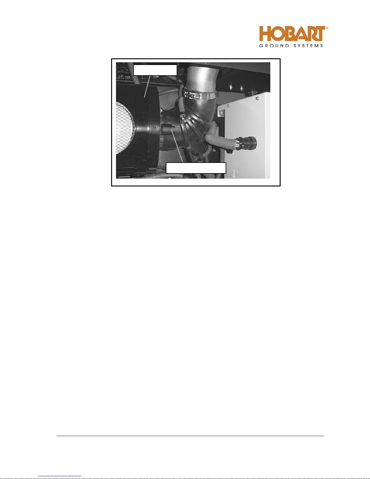
(3) Air Cleaner.
The diesel engine air cleaner is so constructed that air enters through its cylindrical body, and
then is filtered in the process before being passed onto the engine turbo-charger assembly. An
air cleaner service indicator device is mounted on the air cleaner assembly to monitor the airflow
into the air cleaner. As the air cleaner becom es filled with dust, dirt, and car bon, t he intak e
system airflow becomes increasingly restricted. This restriction causes a diaphragm inside the
indicator to move toward an electrical contact. When the maximum allowable restriction level is
reached, the circuit closes and the air cleaner indicator fault appears on the control panel fault
display to warn the operator that the air cleaner must be changed. The electrical indicator
automatically resets when the restriction level drops sufficiently.
Page 23

OM-2228 / Operation and Maintenance Manual
120CU20 / Series 500120 / 400 Hz. Generator Set
October 15, 2013
Chapter 1-1
Page 7
Over temperature or low
Shuts down the engine, and will be
a) Press the engine stop button to
immediate reset.
Low fuel warning and
Turns on the low fuel indication on
a) The low fuel fault indicating
immediate reset.
Clogged air cleaner or
Turns on the air cleaner restriction
a) Press the engine stop button.
immediate reset.
e) Engine faults.
The following is a table listing faults, which may occasionally occur. Column two of the table explains
what happens in the engine’s circuitry when the fault occurs, and column three tells how to return the
generator set to service once the problem is solved. Refer to Chapter 2 for more details on all other
faults.
Engine Fault Condition What Occurs How To Reset
ENGINE FAULTS
oil pressure.
shutdown.
other restriction in the
combustion air inlet.
indicated will appropriate fault
code.
the fault code meter. The GPU is
programmed at the factory to warn
1
/4 tank and to shutdown at 1/8
at
tank.
indicating fault code.
reset the fault code and reset the
protective system.
b) Or use E-STOP button for
function must be reset by
pressing the engine stop button
Fuel must be added prior to
attempting another engine s tar t.
b) Or use E-STOP button for
The restriction must be removed
prior to attempting another engine
start.
b) Or use E-STOP button for
Page 24
OM-2228 / Operation and Maintenance Manual
120CU20 / Series 500120 / 400 Hz. Generator Set
October 15, 2013
Chapter 1-1
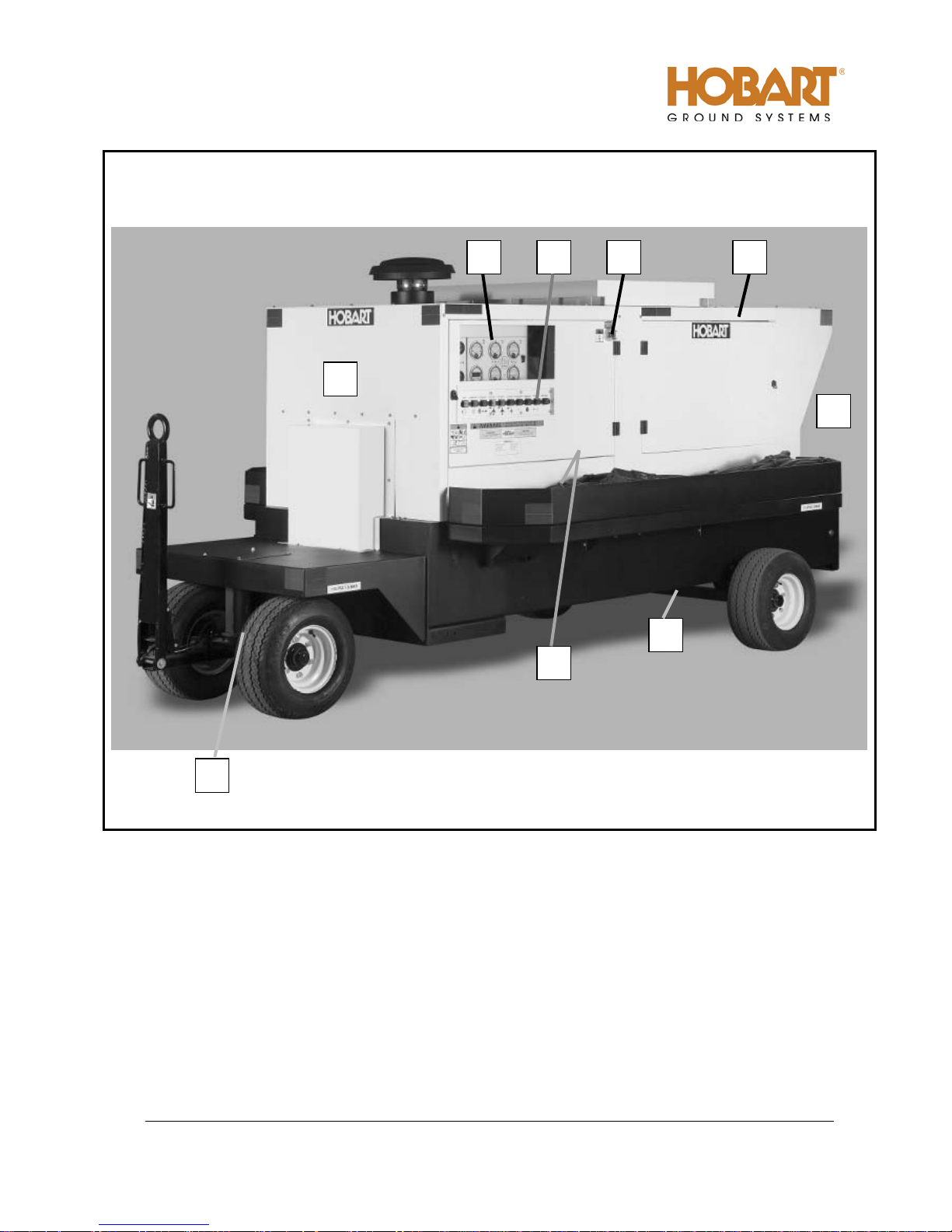
Page 8
4
2 1 3
10
9 8 6
5
1. Control Panel
2. Operator’s Push-button Panel
3. Output Cable Location
4. Front Axle Assembly
5. Rear Axle Assembly
6. Emergency Stop Switch (S28)
7. Exhaust Outlet (Not Shown)
8. Canopy
9. Radiator End (Rear)
10. Generator End (Front)
Figure 1: General Assembly of Generator Set.
Page 25
OM-2228 / Operation and Maintenance Manual
120CU20 / Series 500120 / 400 Hz. Generator Set
October 15, 2013
Chapter 1-1
Page 9
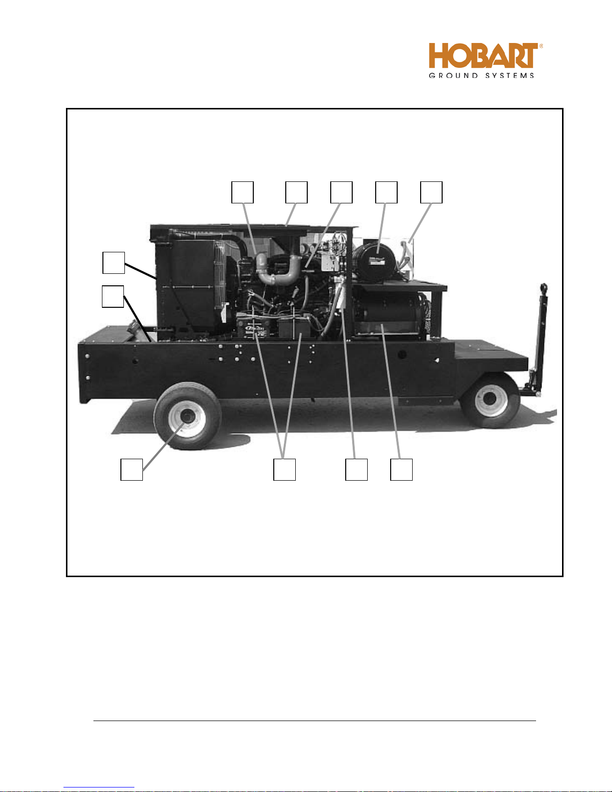
6 5 4 3 2
1
10
11
9 8 7
1. Radiator
2. Charge-Air-Cooler
3. Cummins QSB6.7 Engine
4. Air Cleaner
5. Control Box
6. Fuel Tank
Figure 2: Main Components of Generator Set (Right Side).
7. 12 VDC Batteries (BT1, BT2)
8. Generator
9. Pre-Fuel Filter
10. Rear Axle
11. Air Intake Heater (BH1)
Page 26
OM-2228 / Operation and Maintenance Manual
120CU20 / Series 500120 / 400 Hz. Generator Set
October 15, 2013
Chapter 1-1
Page 10
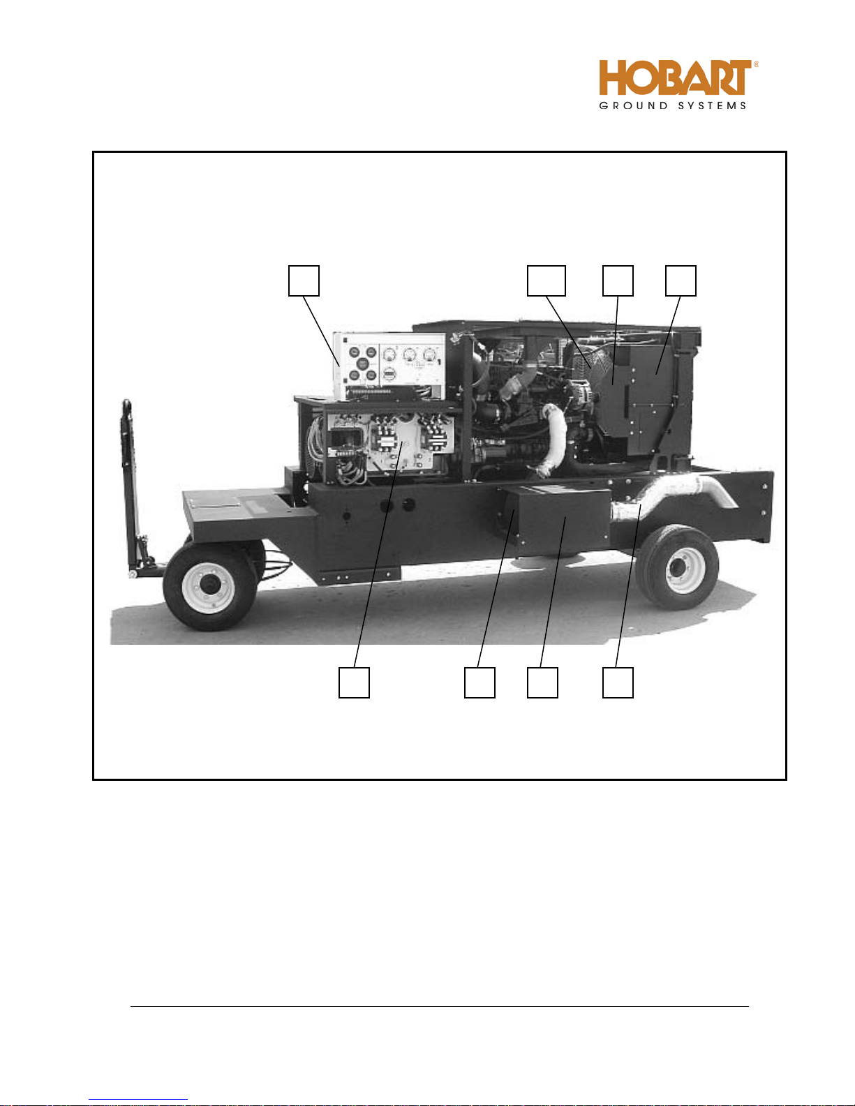
8,9
7 6 4 3 2 1 10
1. Dual Output Power Module
2. Exhaust Muffler Shield
3. Exhaust Muffler
4. Exhaust Piping
5. Lubricity Additive Fuel Filter (Not Shown)
Figure 3: Main Components of Generator Set (Left Side)
6. Top and Bottom Fan Shroud
7. Alternator Fan/Belt Guard
8. Engine Cooling Fan
9. Fan Guard
10. Control Box
Page 27
OM-2228 / Operation and Maintenance Manual
120CU20 / Series 500120 / 400 Hz. Generator Set
October 15, 2013
Chapter 1-1
Page 11
Air Cleaner
Service Indicator
Figure 4: Air Cleaner and Service Indicator
f) Generator.
The 400 Hz generator is a brushless, revolving field, three-phase, alternating current type. The
generator set covered by this manual is a dual-bearing type. The front end of the rotor shaft extends
forward beyond the front bearing and is attached to the engine flywheel by a flexible coupling
assembly. The rear end of the rotor shaft extends rearward beyond the rear bearing and into the
exciter stator housing. The exciter rotor is mounted on this shaft extension with a key and is secured
by a washer and 1/2-13 thread cap screw. A rectifier with six diodes is mounted on the exciter rotor
and converts exciter AC output to DC for excitation of the generator revolving fields. The exciter DC
output to the generator fields, and consequently the generator output, is controlled voltage regulator
PC board (REG). A centrifugal, radial-blade fan, which is part of the flexible coupling assembly,
draws cooling air over all internal windings. Air enters at the exciter end and is discharged at the
drive end. The complete generator assembly is bolted to the engine flywheel housing.
8) Control Box Assembly.
The control box is a sheet metal enclosure that houses and provides mounting facilities for engine and
generator controls and monitoring equipment.
a) Operator Controls.
The control system is divided into three sections. On the left side of the control panel, as one faces it,
are engine meters. On the right side of the control panel are generator meters. Below the control
panel are push-button switches for operating the engine and generator.
Page 28
OM-2228 / Operation and Maintenance Manual
120CU20 / Series 500120 / 400 Hz. Generator Set
October 15, 2013
Chapter 1-1
Page 12
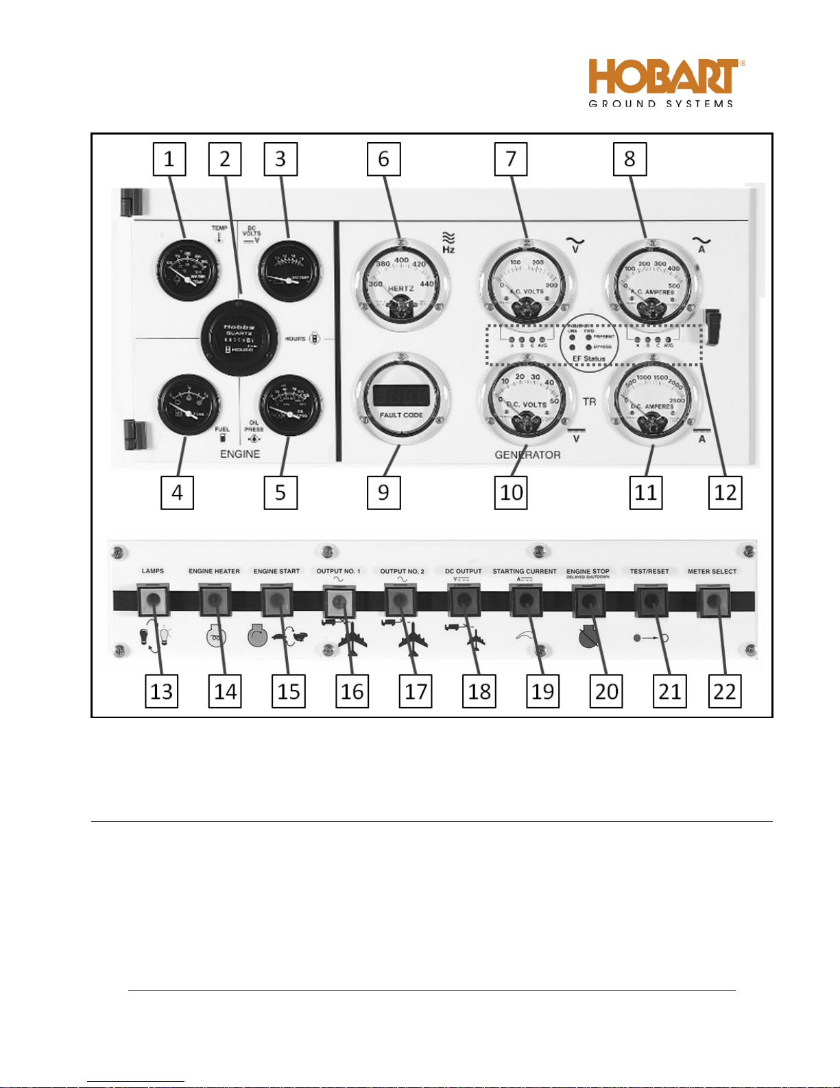
1. Engine Coolant Temperature Gauge (M24)
2. Running Time Meter (M4)
3. Battery Voltmeter (M5)
4. Fuel Gauge (M13)
5. Oil Pressure Gauge (M25)
6. Frequency Meter (M3)
13. Panel Light Switch (S74)
14. Air Intake Heater Switch (S79)
15. Engine Start Switch (S24)
16. AC Output No. 1 Switch (S75)
17. AC Output No. 2 Switch (S275)
7. AC Generator Voltmeter (M2)
8. AC Generator Ammeter (M1)
9. Fault Code Meter (M6)
10. DC Voltmeter [Optional with TR]
11. DC Ammeter [Optional with TR]
12. Front LED Display (A5)
18. DC Output Switch (S430) [Optional with TR]
19. DC Starting Current Switch (S431) [Optional with TR]
20. Engine Stop Switch (S76)
21. Test/Reset Switch (S77)
22. Meter Selector Switch (S3)
Figure 5: Operator Controls.
Page 29

OM-2228 / Operation and Maintenance Manual
120CU20 / Series 500120 / 400 Hz. Generator Set
October 15, 2013
Chapter 1-1
Page 13
(1) Panel lights and pan el li ght push-button switch (S74)
Meters are lighted from inside the control panel. The “LAMPS” push-button switch controls the
lights.
(2) Engine hour meter (M4)
The hour meter is electrically driven from the 12-volt DC battery system. The hour meter
measures and records the engine’s running time and will record up to 9999.9 hours on five
revolving drums. It is only functional when the engine is running.
(3) Engine oil pressure gauge (M24)
The oil pressure gauge is an electrical type that is connected by a wire to an oil pressure sensor
installed in the engine lubricating system. The range is 0 to 125 PSI (0 to 862 kPA).
(4) Engine ON indicating light (DS58)
When the engine is running at idle speed, a green indicating light, within the “ENGINE ST ART ”
push- button switch, flashes at a rate of 1 second on, 1 second off. When the engine is running
at rated speed, the light will stay on continuously.
(5) Engine coolant temperature gauge
The temperature gauge is an electrical type that is connected by a wire to a water temperature
sensor installed in the engine cooling system. The gauge indicates engine coolant temperature in
the range of 100-280 º F (38-138º C).
(6) “ENG IN E START” push-button switch (S24)
The “ENGINE ST ART ” push-button switch, when pressed, connects 12 VDC power to the starter
solenoid coil, which actuates the solenoid switch to connect power to the engine starting motor.
The 12 VDC power is supplied directly to the engine ECM and the oil pressure shutdown switch is
bypassed (This bypass is necessary for engine starting because the low oil pressure switch is
CLOSED until the engine is running normally). The green indicator light with blink.
When pressed a second time, this push-button switch provides a signal to the ECM to adjust the
engine speed to 2000 RPM. The green indicator light will glow continuously. At the same time, a
ground signal is provided to the regulator, enabling the generator to build up voltage for 400-Hz
generator output. Pressing the push-button switch once more removes these signals and the
engine reverts to idle speed and a blinking green indicator light.
(7) “ENGINE HE ATER” push-button switch (S79)
The “ENGINE HEATER” push-button switch activates the standard cold starting aid (manifold air
intake heater), which is totally controlled by the engine’s ECM. Once the heater is activated, the
engine’s ECM will control the operation. The heater typically stays on for a period of
approximately 30 seconds, which is indicated by the light on the push-button. When the light
goes out, the engine is ready to start. Starting a cold engine without first warming the engine will
lead to excessive white smoke exhaust and the engine may be hard to start.
Page 30

OM-2228 / Operation and Maintenance Manual
120CU20 / Series 500120 / 400 Hz. Generator Set
October 15, 2013
Chapter 1-1
Page 14
(8) “EN GI NE STOP” push-button switch (S76).
When the “ENGIN E ST O P” push-button switch is pressed, the red indicator will glow. Then a 3 5 minute delay will occur to permit the turbo and other engine components to cool evenly. After
the delay, power is disconnected from the engine ECM causing the engine to shut down.
(9) Engine voltmeter (M5).
The voltmeter indicates the voltage across the 12 VDC batteries. It is graduated 10 V to 16 V.
(10) Engine fuel gauge (M13).
An electric fuel gauge receives its controlling signal from a sending unit in the fuel tank. 12 VDC
operating power is supplied to the fuel gauge when the “ENGINE START” push-button switch is
pressed. The fuel level can also be checked when the unit is not running by pressing the panel
light “LAMPS” push-button switch.
(11) Fault Code meter and “TEST/RESET” push-button switch (M6, S77)
The function of the fault code meter is to indicate to the operator, that an abnormal condition of
over voltage, under frequency, etc. occurred, which caused the protective monitoring system to
function. When one of the circuits are activated, it shows the code on the fault code meter. The
fault will remain on for a short period or until the “TEST/RESET” push-button switch is pressed.
Pressing the “TEST/RESET” push-button switch can also test the fault code meter operation. A
meter test should be performed only when disconnected from a load, as the contactor(s) will open
during the test cycle.
(12) Engine systems fault codes.
Fault codes will be shown to warn the operator of abnormal engine operations that must be
corrected. These indicators are over temperature, air cleaner restriction, low oil pressure, and
low fuel indication.
(13) AC Generator output monitors (meters).
Three instruments, a frequency meter, a voltmeter, and an ammeter monitor the generator output.
The frequency meter is an analog type and indicates the frequency of the generator output
alternating current in the range of 360 to 440 Hz (cycles per second). The voltmeter indicates the
generator output voltage in each phase-to-neutral (A-N, B-N and C-N) or phase-to-phase (A-B, BC and C-A) as selected by the “METER SELECT” switch. The voltmeter has a scale of 0 to 300
V. The ammeter has a scale of 0 to 500 A. The amperage value in each of the three phases
may be read on the ammeter by selecting the desired phase with “METER SELECT” switch. The
ammeter current transformers, located in the output power module circuit, lower the output load
current to a lesser value, of definite ratio, which is sent to the Voltage Regulator PC Board (REG).
The ammeter dial scale is numbered so that the pointer will indicate the true load current value.
(14) Load contactor indicating lights [Yellow # 1 and Orange # 2] (S75, S275)
Indicating lights within the respective contactor control push-button switches (“OUTPUT NO. 1”
and or “OUTPUT NO. 2”) glow when the circuit is energized, indicating that power is available at
the plug. When the load contactor opens for any reason, the light is turned OFF.
Page 31

OM-2228 / Operation and Maintenance Manual
120CU20 / Series 500120 / 400 Hz. Generator Set
October 15, 2013
Chapter 1-1
Page 15
(15) Front LED Display (A5).
The front LED display indicates, which voltage (A-N, A-B, etc…) and amperage are shown on the
meters and whether “EF BY-PASS” is present or bypassed. This “EF BY-PASS” indicator
serves to warn the operator that if the plug interlock system was by-passed any exposed cable
may be live.
(16) DC Generator output monitors (meters) [with DC option].
Two instruments, a voltmeter and an ammeter, monitor and display the transformer-rectifier’s
output. The voltmeter and ammeter meters are both analog type and indicate the output voltage
from 0 to 50 VDC and the amperage from 0 to 2500 A.
(17) “STARTING CURRENT” Switch (S431) [with DC option].
Each time the “STARTING CURRENT” push-button switch is pressed, the BLU E ind icat or wil l
glow. The present current limiting amperage setting will be displayed on the fault code meter for
a short time delay, before incrementing, at 100 A increments, up to 2500 A. Once 2500 A has
been reached, the incrementing will start over from the beginning.
(18) “DC OUTPUT” Contactor Switch (S430) [with DC option].
Each time the “DC OUTPUT” push-button switch is pressed, the BLUE indicator will glow when
the circuit is energized, indicating that power is available at the plug. When the load contactor
opens for any reason, the light turns OFF.
Page 32

OM-2228 / Operation and Maintenance Manual
120CU20 / Series 500120 / 400 Hz. Generator Set
October 15, 2013
Chapter 1-1
Page 16
b) Control Box Interior Components.
1. Control Box Wrapper
2. Engine Specific PC Board [ESB] (A1)
3. Engine Interface PC Board [EIB] (A2)
4. Digital Control PC Board [CTL] (A3)
5. Voltage Regulator PC Board [REG] (A4)
6. Transformer-Rectifier PC Board [TRB] (A404)
{Optional}
Figure 6: Control Box Interior Components.
(1) EF Bypass switches (located on CTL)
For each load contactor circuit, a single-pole, single-throw “EF1 BYPASS” for “OUTPUT 1” or
“EF2 BYPASS” for “OUTPUT 2” provides a means of bypassing the 28 VDC interlock circuit for
that contactor when supplying power to a load bank or to an aircraft not equipped with a plug
interlock system.
7. +5, -12 VDC Power Supp l y (PS1)
8. Circuit Breaker Support Bracket
9. Marker Lights Circuit Breaker, 10 A (CB1)
10. Engine Circuit Breaker, 10 A (CB4)
11. Controls Circuit Breaker, 5 A (CB7)
Page 33

OM-2228 / Operation and Maintenance Manual
120CU20 / Series 500120 / 400 Hz. Generator Set
October 15, 2013
Chapter 1-1
Page 17
(2) Regulated-diagnostic switch (located on the REG).
When the “REGULATED/DIAGNOSTIC” switch is in the “REGULATED” (down) position, the
generator output voltage is regulated by the PC board for 115/200 VAC output to an aircraft.
When this switch is placed in the “DIAGNOSTIC” (up) position, 12 VDC is applied to the
generator exciter with the engine running at rated RPM, in order to check the operation of the
generator. This is done to determine if a particular power output malfunction is caused by a
defective generator or by a defective voltage regulator. When this switch is in the
MAINTENANCE position, no current is supplied to the generator exciter. In this condition, a lowlevel, unregulated voltage of approximately 30 VAC will be produced at the generator output
terminals due to the residual magnetism of the exciter.
(3) Circuit breakers (CB1, CB4, CB7)
A 10-ampere “ENGINE” circuit breaker, protects the 12 VDC engine electrical and fault circuits,
and another 10-ampere “MARKER LIGHTS” circuit breaker protects the 12 VDC lighting system.
A 5-ampere “CONTROL” circuit breaker protects the 12 VDC control system.
(4) Digital Control PC Board [CTL] (A3)
The digital control PC board is the center for all communications throughout the entire control
system. All push-button panel commands run through the digital control PC board, which
communicates the commands to the appropriate area (i.e. other PC boards) in the control
system. The digital control PC board also controls the real time clock, monitors the over/under
voltage and overload protection, push-button panel indicator lights, generator output meters, EF
bypass switches, and communicates with the optional service tool.
Figure 7: Digital Control PC Board
Page 34

OM-2228 / Operation and Maintenance Manual
120CU20 / Series 500120 / 400 Hz. Generator Set
October 15, 2013
Chapter 1-1
Page 18
(5) Engine Interface PC Board [EIB] (A2).
The EIB is common between all engine models and monitors coolant temperature, oil pressure,
battery voltage, and fuel tank level monitoring. The EIB is also responsible for the monitoring the
warning switches for high coolant temperature, low oil pressure, high air restriction, and low
coolant level (optional). The warning switches signal the EIB when a fault occurs, which then the
EIB relays this information to the CTL. The CTL will issue the command to the system that fits
the fault event.
The EIB also controls the power distribution in the control system, hour meter, lights, and the
engine starter operation.
(6) Engine Specific PC Board [ESB] (A1).
The ESB is unique only to the engine model used in the GPU purchased. The ESB is the primary
interface between the control system and the engine’s electronic control module. When the CTL
senses the engine start button has been pressed it signals to the ESB, which then communicates
to the engine control module what mode of operation is required (idle or rated speed).
The ESB controls the “FREQUENCY ADJUST” switch that is used to enable the “FREQUENCY
ADJUST ENABLE/DISABLE” potentiometer to test the over/under frequency fault limits of the
generator set system. The ESB also controls the “DATA REQUEST” button and diagnostic
indicator light to read the engine’s ECM diagnostic error codes.
Figure 8: Engine Interface PC Board.
Page 35

OM-2228 / Operation and Maintenance Manual
120CU20 / Series 500120 / 400 Hz. Generator Set
October 15, 2013
Chapter 1-1
Page 19
Figure 9: Engine Specific PC Board.
(7) Voltage regulator PC board [REG] (A4).
Figure 10: Voltage Regulator PC Board.
Page 36

OM-2228 / Operation and Maintenance Manual
120CU20 / Series 500120 / 400 Hz. Generator Set
October 15, 2013
Chapter 1-1
Page 20
This voltage regulator PC board is designed to provide voltage regulation for a three-phase, fourwire, 115/200-volt, 400-Hz brushless alternator. This regulator provides field excitation power as
required to meet varying alternator load conditions to hold the alternator voltage constant. In
addition, the voltage regulator PC board circuitry provides line drop compensation. Any deviation
of the alternator voltage from its set, regulated level is sensed at the voltage regulator PC board.
The sensing signal is compared to a reference signal, and, with associated circuitry, varies the
field power supplied to the rotary exciter.
a When the machine is started and the engine is at rated speed, the rotary exciter is excited
from alternator residual magnetism through the half-wave rectifier-bridge, located on the
voltage regulator PC board assembly. As the rotary exciter voltage inc reas es , alt e r nator
excitation increases and the alternator voltage builds up. The sensing circuit of the voltage
regulator PC board then compares the input voltage to a reference voltage and adjusts the
field power of the rotary exciter to bring the voltage into regulation limits.
b When the alternator is loaded, its terminal voltage decreases, lowering the rectified three-
phase voltage of the voltage sensing circuit. The sensing voltage is low in respect to its
reference voltage, causing the voltage regulator PC circuitry to increase the power to the field
of the rotary exciter. The alternator voltage increases until the voltage returns to its regulated
value.
c When a load is removed from the alternator, the alternator voltage rises. The rectified three-
phase voltage-sensing signal increases, causing this signal to be higher than the reference
signal. The associated voltage regulator circuitry causes the field power of the rotary exciter
to decrease, lowering the alternator voltage until the voltage returns to regulated value. The
line drop voltage compensation circuit consists of a current transformer on each phase of the
load circuit, and fixed resistance in parallel with each current transformer. The current
transformers detects the magnitude of current flowing through the power cables from the
alternator to its load and feeds a signal into the voltage regulator PC board. The PC board
processes this signal to change the output voltage proportional to the current draw. The
regulator output increases slightly so that the alternator output voltage is equal to the
regulated voltage plus the voltage drop in the lines. The line drop compensation
potentiometer may be adjusted to match exactly the voltage drop of the power cables
carrying the load current.
The under/over frequency protection, EF signal, and lost neutral detection are also monitored by
the REG and will signal the CTL when a fault has occurred. The CTL issues the appropriate
command that corresponds to the fault.
(8) Transformer-Rectifier PC Board [TRB] (A404) {optional}.
The TRB PC Board is only used when the optional 28.5 VDC transformer-rectifier assembly is
installed. The TR monitors the output voltage, output current, controls the input and output
contactors, and monitors all fault events associated with the DC output. When a fault event does
occur, the TRB relays this information to the CTL. The CTL will issue the command to the system
that fits the fault event.
(9) +5, -12 VDC Power Source (PS1.)
Supplies the internal power distribution of +5 VDC and –12 VDC into the control system.
Page 37

OM-2228 / Operation and Maintenance Manual
120CU20 / Series 500120 / 400 Hz. Generator Set
October 15, 2013
Chapter 1-1
Page 21
Figure 11: Transformer-Rectifier PC Bo ard
Figure 12: Control System Power Source.
Page 38

OM-2228 / Operation and Maintenance Manual
120CU20 / Series 500120 / 400 Hz. Generator Set
October 15, 2013
Chapter 1-1
Page 22
9) Power Module Panel Assembly.
The power module panel assembly, sometimes referred to as the contactor panel, is located at the left
front of the machine under the control box. The panel assembly provides a means of connecting and
disconnecting generator output to and from the load (aircraft).
a) Load contactor(s)
The load contactor(s) each contain a magnetic operating coil and four sets of contacts. The three
larger contacts conduct three-phase AC generator output. A small contact set is connected to the
Digital Control PC Board (CTL) to activate the protective monitor circuit. Three-phase, 400-Hz
generator output power is conducted to the load contactors by 2/0 cables that pass through current
transformers.
b) Current transformers (CT1-CT6)
On each individual output a set of current transformers are used to monitor and control the line-drop
compensation, ammeter, and overload circuit.
(1) Line-Drop Compensation
The current transformers detects the magnitude and power factor of current flowing from
generator to load. They feed a signal to the voltage regulator that interprets the signal and alters
the exciter field current as required to maintain a constant predetermined voltage at the load.
(2) Ammeter
The current transformers convert a current signal to a voltage signal, which is sent to the Voltage
Regulator PC Board (REG). The ammeter is really a voltmeter graduated and numbered in
amperes to show current proportional to the voltage signal received.
When there is overload on the output for more than 5 minutes (load exceeding 326 amperes per
output or 125% of rated load), the main overload sensing circuit sends signals the load the
contactor(s) circuit to open both load contactors.
(3) Overload, No 1 and/or No. 2 output
On each individual output the current transformers converts a current signal to a voltage signal.
The voltage signal is sent to the ammeter and to the overload monitoring circuit for that output.
The overload monitoring circuit will open the contactors when the output current reaches 125% of
the normal rated output current. The monitoring circuit moniters each individual output, as well
as, the overall current for a dual output machines.
The following is a list of overload module characteristics:
• At 125% load the module will function in 5 minutes.
• At 150% load the module will function in 30 seconds.
• AT 200% load the module will function in 10 seconds.
NOTE: The overload protective system will function when any phase carries 123% to 127% of
rated load. All times are plus or minus 25% and are non-adjustable.
Page 39

OM-2228 / Operation and Maintenance Manual
120CU20 / Series 500120 / 400 Hz. Generator Set
October 15, 2013
Chapter 1-1
Page 23
Generator Output Leads
Current Transformers
Output Contactors
Figure 13: Output Power Module Components.
Page 40

OM-2228 / Operation and Maintenance Manual
120CU20 / Series 500120 / 400 Hz. Generator Set
October 15, 2013
Chapter 1-1
Page 24
Charge-Air-Cooler
Intake Air
10) Cold Weather Starting System (BH1)
The intake air heater, located on the intake manifold, is used for starting the engine at very cold
temperatures and reduces the white smoke associated with a cold start. This cold weather starting
system is a fully automatic once engaged by the operator (Chapter 1, Section 3). The intake air heater
(or grid heater) is energized or de-energized from a power relay controlled by the ECM. The amount of
time the air intake heaters stay on, in the preheat phase, is a function of the intake manifold temperature
at start up. (The pre-heat time increases with colder intake manifold temperatures). The maximum
duration of the pre-heat phase is around 30 seconds. During cranking, the intake air heater is turned off
to allow maximum current to be used by the starter .
CAUTION
Never use an ether start system in conjunction with the air intake heater.
Figure 14: Intake Air Heater.
Intake Air Heater
Page 41

OM-2228 / Operation and Maintenance Manual
120CU20 / Series 500120 / 400 Hz. Generator Set
October 15, 2013
Chapter 1-1
Page 25
11) Transformer-Rectifier Assembly Components.
The T-R provides a regulated output voltage of 28.5V DC. Input power is provided to the DC components
from the 115/200 volt, 400 Hz generator set, through an input contactor. The output contactor provides
DC power to the load. If during DC operation, AC power is required, the DC output voltage will no longer
be regulated once the AC output contactor is closed. The AC voltage regulator will take over regulating
the AC output voltage. The DC voltage will drop during full load applications when the simultaneous
operation is used.
a) Transformer Assembly (T401).
This transformer assembly steps down the generator’s output (115/200 VAC, 3 phase, 400 Hz) to 25
VAC. The smaller voltage is rectified by the six diode rectifiers, located on the heat sink assembly.
b) Heat Sink / Diode Assembly (CR402-CR407).
This assembly rectifies the AC voltage from transformer assembly, providing unfiltered 28.5V DC. A
DC shunt connected to the heat sink assembly measures the DC output current.
c) Input Con tactor (K401).
The input contactor applies the generator output power to the input of the transformer assembly.
d) Output Contactor (K402).
The output contactor connects the output of the 28.5 VDC power supply to the output cables. The
contactor is located on the right side under the T-R Assembly.
e) DC Ind u ctor / Filter Assembly (L401).
The DC inductor filters the raw 28.5 VDC from the diode assembly and provides low ripple 28.5 VDC
output.
f) Pre-Load Resistors (R402-R404).
The three 10-ohm, 100-Watt pre-load resistors provide a minimum output load on the DC output.
g) Capacitor PC Board (A401).
The DC capacitor PC board works with the DC inductor as a filter to produce a low ripple 28.5 VDC
output voltage.
h) Control Interlock Kit (Optional).
This optional assembly is used for applications requiring a safety interlock signal being sent back
from the aircraft before closing the output contactor to delivery power to the load. See Chapter 4,
Section 3 for details of the assembly and Chapter 5 for schematics and connection diagrams.
Page 42

OM-2228 / Operation and Maintenance Manual
120CU20 / Series 500120 / 400 Hz. Generator Set
October 15, 2013
Chapter 1-1
Page 26
1. Transformer Assembly (T401)
2. Heat Sink / Diode Assembly (CR402-CR407)
3. Input Contactor (K401)
4. Output Contactor (K402)
Figure 15.Transformer-Rectifier C o m p o n ents.
5. DC Inductor / Filter Assembly (L401)
6. Pre-Load Resistors (R402-R404)
7. Capacitor PC Board (A401)
Page 43

OM-2228 / Operation and Maintenance Manual
120CU20 / Series 500120 / 400 Hz. Generator Set
October 15, 2013
Chapter 1-2
Page 1
Section 2
Preparation for: Use, Stor a ge, or S hipping.
Lubricating oil capacity (w/ filter)
4 gallons (15.1 liters)
Coolant capacity system
10 gallons (37.8 liters)
1) Preparation for Use.
a) Inspection/Check.
Inspect the unit thoroughly prior to operation.
(1) Remove blocking, banding, ties, and other securing material.
(2) Inspect exterior for shipping damage such as broken lights, damaged sheet metal, etc.
(3) Open all canopy doors and inspect interior for foreign material such as rags, tools, shipping
papers, etc.
(4) Check fuel, coolant, oil hoses and connections for visible leaks. Visually inspect the compartment
floor and ground surface under the unit for signs of leakage. Correct any leaks by tightening hose
clamps, tube fitting, etc. as required.
(5) Check security of generator set retaining components.
(6) Check the following for sufficient quantity:
a Fuel
Press the “LAMPS” push-button button to energize the fuel gauge when the engine is
stopped. Fuel is supplied from a customer-furnished source.
NOTE: For recommended fuel specifications refer to the Engine Manufacturers Operation and
Maintenance Manual provided wi th this manual.
b Engine coolant
Remove radiator cap to check coolant level. Coolant level should be at the bottom of the filler
neck.
CAUTION
NOTE: For antifreeze protection, use a solution of 50% permanent antifreeze (Ethylene glycol) and
50% clean water.
BE SURE the cooling system antifreeze solution is adequate to protect below the
lowest temperature expected.
ENGINE OIL AND COOLANT CAPACITIES
Figure 1.
Page 44

OM-2228 / Operation and Maintenance Manual
120CU20 / Series 500120 / 400 Hz. Generator Set
October 15, 2013
Chapter 1-2
Page 2
Oil Fill
Dipstick
c Engine lubricating oil level
The oil gauge rod has “H” high mark and “L” low-level marks to indicate the operating
lubrication oil supply. Oil level should be kept as near the high mark as possible, without
going over it. See Figure 1 for capacity.
CAUTION
NEVER operate the engine with oil level below the “L” level mark or above the ”H”
level mark.
NOTE: See the Engine Manufacturer’s Operation Maintenance Manual for oil recommendations.
d Check Batteries
b) Installing Three-Phase AC Output Cables.
The generator set may be shipped without aircraft cables. The output cables connect to the load
contactors, which are located on the power module assembly (left side of the unit beneath the engine
control panel).
The conductor size recommended for AC output cables is 2/0 AWG. Use No. 12 size for control (E
and F) terminals. Large cables (A, B, C, and N) should be equipped with terminals having at least a
3/8-inch diameter mounting hole. Mounting hole in small leads (E and F) should be at least 1/4-inch
diameter.
Inspect the batteries for proper connection of the terminals and check the electrolyte level (if
possible). Service or replace if necessary.
Figure 2
Oil Fill and Oil Level Check Locations.
Page 45

OM-2228 / Operation and Maintenance Manual
120CU20 / Series 500120 / 400 Hz. Generator Set
October 15, 2013
Chapter 1-2
Page 3
To install AC output cables proceed as follows:
(1) Open control box door of the generator set and remove the lower panel.
(2) Remove Plexiglas cover in front of the power module assembly.
(3) Remove the cover panel on the cable tray covering the cable clamps.
(4) Loosen screws on cable clamps.
(5) Route cables through cable clamps, and up to the load side of the load contactor(s).
(6) Connect the phase cable terminal lugs to the appropriate terminal studs on the contactor(s): cable
lug “A” to terminal stud “A”, “B” to “B”, and “C” to “C”.
(7) Connect the cable’s neutral terminal lug securely to the neutral (ground) stud on the power
module assembly.
(8) Connect the “E” and “F” cables to the “E” and “F” studs on the power module assembly.
(9) Tighten clamp screws securely, but avoid damage to cable insulation.
(10) Replace Plexiglas cover panel, lower panel, and close canopy door.
c) Installing the DC Output Cable (optional).
(1) The T-R output cable is not normally supplied unless specifically ordered. For normal aircraft
service, use cable assembly, MS90347, with 4/O size cables having a positive and negative
connection.
(2) The output cable is extended through the canopy via the supplied hole and bracket in the frame
assembly (See Figure 3).
(3) The cables will be connected to the output contactor, located under the TR assembly on the right
side (See Figure 4).
Page 46

OM-2228 / Operation and Maintenance Manual
120CU20 / Series 500120 / 400 Hz. Generator Set
October 15, 2013
Chapter 1-2
Page 4
Output Cables
Contactor
Output Cables
Clamp
Figure 3 Output Cable Connection
Figure 4 Lower Panel Assembly
Page 47

OM-2228 / Operation and Maintenance Manual
120CU20 / Series 500120 / 400 Hz. Generator Set
October 15, 2013
Chapter 1-2
Page 5
2) Preparation for Storage.
When a generator set is to be stored or removed from operation, special precautions should be taken to
protect the internal and external parts from rust, corrosion, and gumming in the engine fuel system.
a) General
Pull all circuit breakers and/or disconnect battery negative terminal.
(1) The unit should be prepared for storage as soon as possible after being removed from service.
(2) The unit should be stored in a building which is dry and which may be heated during winter
months.
(3) Moisture-absorbing chemicals (Hobart Part No. 76A1354-001) are available for use where
excessive dampness is a problem; however, the unit must be completely packaged and sealed if
moisture-absorbing chemicals are to be effective.
b) Temporary Storage.
When storing the unit for 30 days or less, prepare as follows:
(1) Lubricate the unit completely in accordance with instructions in Section 2-2. This will include
changing engine oil, and all filter elements.
(2) Start the engine and operate for about two minutes so that all internal engine components will be
coated with new oil.
NOTE: Do not drain the fuel system or crankcase after this run.
(3) Make certain the cooling system antifreeze solution is adequate to protect below the lowest
temperatures expected during the storage period. Be sure the solution is thoroughly mixed.
(4) Clean the exterior of the engine. Dry with clean rags and compressed air.
(5) Seal all engine openings. Use a waterproof, vapor proof material that is strong enough to resist
puncture damage from air pressures.
c) Long Time Storage (Over 30 Days).
To protect the generator and other electrical components, the complete unit should be packaged
using moisture proof packaging material and sealing material. Place containers of moistureabsorbing chemicals (Hobart Part No. 76A-1354-001) in the unit before packaging. The unit may be
stored for long periods with no special preparation if it is possible to operate the engine once each
week. When starting once a week proceed as follows:
(1) Make certain the cooling system is adequately protected.
WARNING
ENSURE adequate ventilation bef ore star ti ng the eng i ne.
Page 48

OM-2228 / Operation and Maintenance Manual
120CU20 / Series 500120 / 400 Hz. Generator Set
October 15, 2013
Chapter 1-2
Page 6
(2) Start the engine and operate under full load until coolant temperature has reached at least 176ºF
(80ºC).
(3) While the engine is running, ensure that normal operating controls are in good working condition
before shutdown and storage. If weekly operation is not possible, contact the nearest engine
manufacturer distributor for instructions.
3) Preparation for Shipment.
a) Disconnect battery negative terminal before shipping.
b) During long shipments, vibration, jolting, etc may loosen the generator set retaining hardware.
CAUTION
NOTE: It is suggested that strong banding be used to secure the generator set, or a strong steel bar
be either welded or bolted across the front of the generator set frame.
When shipping the unit, provide sufficient retaining materials to ensure the generator
set cannot roll out or off the vehicle in which it is being transported.
Page 49

OM-2228 / Operation and Maintenance Manual
120CU20 / Series 500120 / 400 Hz. Generator Set
October 15, 2013
Chapter 1-3
Page 1
Section 3
Operation.
1) General.
This section contains information and instructions for the safe and efficient operation of the equipment.
Operating instructions are presented in step-by-step sequence of procedures to be followed in supplying
400-Hz power.
NOTE: Read ALL of the operating instructions before attempting to operate the equipment.
WARNING
Ear protection equipment may be necessary when working close to this equipment.
2) 400 Hz. Operating Procedure.
a) Pre-start Inspection
(1) Be sure the fuel shutoff valve on the unit is open.
(2) Ensure 12 VDC po wer is ava ilabl e to the engin e starti ng s ystem .
(3) Check the engine and generator compartments to make certain they are free of rags or other
foreign materials.
(4) Make certain there is sufficient lubricating oil and coolant in the engine.
(5) Check that all circuit breakers are reset.
(6) Make certain the “STARTER ENABLE/DISABLE” switch is enabled, and the “FREQUENCY
ADJUST” switch is disabled.
Page 50

OM-2228 / Operation and Maintenance Manual
120CU20 / Series 500120 / 400 Hz. Generator Set
October 15, 2013
Chapter 1-3
Page 2
1. Engine Coolant Temperature Gauge (M24)
2. Running Time Meter (M4)
3. Battery Voltmeter (M5)
4. Fuel Gauge (M13)
5. Oil Pressure Gauge (M25)
6. Frequency Meter (M3)
13. Panel Light Switch (S74)
14. Air Intake Heater Switch (S79)
15. Engine Start Switch (S24)
16. AC Output No. 1 Switch (S75)
17. AC Output No. 2 Switch (S275)
7. AC Generator Voltmeter (M2)
8. AC Generator Ammeter (M1)
9. Fault Code Meter (M6)
10. DC Voltmeter [Optional with TR]
11. DC Ammeter [Optional with TR]
12. Front LED Display (A5)
18. DC Output Switch (S430) [Optional with TR]
19. DC Starting Current Switch (S431) [Optional with TR]
20. Engine Stop Switch (S76)
21. Test/Reset Switch (S77)
22. Meter Selector Switch (S3)
Figure 1: Operator Controls
Page 51

OM-2228 / Operation and Maintenance Manual
120CU20 / Series 500120 / 400 Hz. Generator Set
October 15, 2013
Chapter 1-3
Page 3
b) Normal Engine Starting Procedures.
Engine starting procedures are outlined below. The engine’s operating controls and monitoring
instruments are illustrated in Figure 1.
CAUTION
CAUTION
CAUTION
Refer to operating instructions in the engine manufacturer’s operation manual, when
starting engine for the first time.
NOTE: The engine manufacturer’s operation manual is provided with this manual.
(1) If illumination is required, press “LAMPS” push-button switch one time. Pressing this button
switch also activates the fuel gauge.
(2) On days when the ambient temperatures are below 60° F, press the “ENGINE HEATER” push-
button to engage the air intake heater prior to starting the engine. The light in the button will
illuminate when the intake heater is engaged (if the light does not illuminate, the engine is ready
to start) and will go off when the intake heater is disengaged, thus signifying the engine is ready
to start.
Never use an ether start system in conjunction with the air intake heater.
(3) Press the green “ENGIN E START” push-button switch and hold until engine starts. The engine
will start at idle speed, and the green light in the “ENGI NE START” push-button switch will flash
to indicate that power is available to the engine’s ECM circuit.
Do not attempt to bring to rated speed for at least 5 seconds after engine starts.
Damage to the starter and flywheel will result.
CAUTION
If the engine fails to start, the control system will automatically disable the starting
motor and indicate a low oil pressure fault. The emergency stop switch must be
pressed to reset the control system and allow another starting attempt. If the engine
fails to start after four attempts, an inspection should be made to determine the cause.
If the engine fires sufficiently to disengage the starter gear, but does not start, allow
the starting motor to come to a complete stop before attempting to engage the starter
again, then press the start pushbutton switch.
(4) Check oil pressure to make certain that it is normal and observe all other engine instruments for
normal operation.
(5) Allo w engin e to idle and wa rm for 3 - 5 minutes before bringing it up to rated speed.
Page 52

OM-2228 / Operation and Maintenance Manual
120CU20 / Series 500120 / 400 Hz. Generator Set
October 15, 2013
Chapter 1-3
Page 4
CAUTION
To eliminate the possibility of wet stacking (See Appendix A), DO NOT allow the
engine to idle for long periods.
c) Failed Starting Procedure.
CAUTION
To prevent damage to the starting motor, do not engage the starting motor for more
than 30 seconds. Wait two (2) minutes between each attempt to start.
In the event that the engine fails to start, the circuitry must be reset before the next attempt. To do
this:
(1) Push the red “EMERGENCY STOP/RESET BUTTON” on the control box door to the right of the
control panel.
(2) Pull the red “EMERGENCY STOP/RESET BUTTON” back out before the next attempt to start
the generator set.
d) Power Delivery
(1) Press “ENGINE START” pushbutton switch a second time to bring engine from idle speed to
rated speed. The ECM will immediately increase engine speed to 2000 RPM and maintain it.
The voltage build-up will occur automatically. In addition, the green indicating light in the
“ENGINE START ” push-button switch will glow continuously.
(2) Observe generator instruments. The frequency meter should indicate exactly 400 Hz. With the
“METER SELECT” pushbutton switch set to read any line-to-neutral position, (A-N, B-N, or C-N),
the voltmeter should read 115 volts. With the “METER SELECT” pushbutton switch set to any
line-to-line position, (A-B, B-C, or C-A), the voltmeter should read 200 volts.
(3) The final step in delivering power is closing one or both of the load contactors. When the
instruments indicate satisfactory frequency and voltage values, close either load contactor (or
both load contactors) by momentarily pressing the load contactor(s) (“OUTPUT NO. 1” or
“OUTPUT NO. 2”) pushbutton switch. The yellow or orange indicating light of the pushbutton
switch that is pressed will glow continuously, indicating that the load contactor is closed and
power is available at the aircraft.
(4) Early in the power delivery run it is recommended that the operator check output voltage and
current in each of the three phases. Use the “METER SELECT” pushbutton switch to select the
either the line-to-line or line-to-neutral voltage. If the load is changing, observe the instruments
until load conditions stabilize.
CAUTION
NEVER press the test/reset pushbutton switch while power is being delivered.
The contactors will open and power to the aircraft will be suddenly interrupted.
(5) A condition of over-voltage, under-voltage, under-frequency, over-frequency, or overload in the
output circuit will automatically open the load contactor and display a fault code to signal the
operator which of the above faults caused the protective monitor system to operate. After the
fault has been corrected, press the “TEST/RESET” push-button switch to reset the protective
relay system. Proceed with power delivery by operating the load contactor pushbutton switch.
Page 53

OM-2228 / Operation and Maintenance Manual
120CU20 / Series 500120 / 400 Hz. Generator Set
October 15, 2013
Chapter 1-3
Page 5
WARNING
NEVER disconnect the output cable while power is being delivered. Output
contactors must be open prior to removal of the cable from the aircraft.
CAUTION
The generator set must be shut down so that the failed power delivery problems can
be diagnosed. Only licensed technicians should work on this generator set.
e) Failed Power Delivery.
If the contactor indicating light goes out approximately two seconds after the output pushbutton switch
is released, and the fault code meter shows an EF1 or EF2 fault code, this indicates that the aircraft is
not supplying the 28.5 VDC interlock signal to the plug interlock circuit. Correct the condition and
again press the output pushbutton switch.
The “REGULATED/DIAGNOSTIC” switch (located on the voltage regulator PC board) must be set to
“NORMAL” for power delivery.
If the aircraft (or load bank) does not have the 28.5 VDC signal, set the EF Bypass ON/OFF switch
(located on the digital control PC board) to the “ON” position.
See “Load Contactor Operating Circuits” in Section 2-4 for other for additional troubleshooting
procedures.
f) Discontinue Power Delivery with Unit Shutdo wn.
(1) Normal conditions
a Push the “OUTPUT” (No. 1 or No. 2) pushbutton switch to open the output load contactor.
The indicating light (yellow or orange depending on the contactor used) on that switch will go
OFF immediately to indicate that the load contactor has opened and power is no longer being
delivered to the aircraft. The engine will remain at rated speed.
b Push the red “ENGINE STOP” pushbutton switch once to bring the engine down to idle
speed. This will begin the automatic shutdown sequence to shut off the engine, gauges,
lights, etc., after approximately 3 - 5 minutes.
c Disconnect output cable from aircraft after engine is at idle speed only.
(2) Emergency conditions
a Depress the “EMERGENCY STOP BUTTON” located on the control box door to the right of
the control panel. When pushed this button instantly shuts the generator set off. Pull the
button back out to reset it before restarting the generator set.
CAUTION
Do not use the “EMERGENCY STOP BUTTON” button as a normal shutdown device.
Damage to the engine turbo charger may result without proper cooling time. Use the
“ENGINE STOP” push-button for all normal engine shutdowns.
Page 54

OM-2228 / Operation and Maintenance Manual
120CU20 / Series 500120 / 400 Hz. Generator Set
October 15, 2013
Chapter 1-3
Page 6
3) DC Operating Procedure (optional).
This section describes the operation of the optional DC unit. The DC output voltage value, which is
controlled by a potentiometer on the Transformer-Rectifier Board (TRB), need only be set once. The
voltage level will remain the same for all future operations, even when the unit is shut down or the battery
is disconnected. It may, however, be changed as often as desired.
Note: The DC output voltage is only regulated when operating DC alone without an AC output. If AC
and DC are operated together, only the AC voltage is regulated.
a) Normal Power Delivery.
(1) Connect the output cable plug connector to the aircraft receptacle. Be sure connector is mated
fully and securely.
(2) The engine should be running at rated speed (2000 RPM) and generating 115/200 VAC. If not,
reference the engine starting procedure above.
(3) Press “DC OUTPUT” push button to close the DC output contactor. The blue “DC OUTPUT”
lamp glows to indicate that DC power is being delivered to the aircraft.
b) Current Limiting Power Delivery.
If current limiting is required for starting an aircraft, set the current limit as follows:
(1) Press the “STARTING CURRENT” push button to activate and view the present current limiting
value. Continue to hold the button down to increase the setting.
(2) Each time the “STARTING CURRENT” push button is pressed the current limiting will be viewed
and increased by 100 A until it reaches the maximum setting of 2500 A. At that time the current
limiting will reset to the beginning and start the 100 A increments again. Set the current limit to
the desired setting.
c) Discontinue Power Delivery.
(1) Press “DC OUTPUT” push button to open the DC output contactor. The blue “DC OUTPUT”
lamp turns off to indicate that DC power has been removed from the aircraft.
(2) Disconnect the output cable connector from the aircraft receptacle and store properly in the
GPU’s cable tray.
4) Simultaneous AC and DC Operation.
If both 28.5 VDC and 400-Hz AC power must be delivered at the same time, the operation of the controls
remains the same. However, the DC output voltage will not be regulated when the AC voltage contactor
is closed and is supplying power.
When both AC and DC are being used and a fault condition occurs, the system’s response to the fault is
given priority over all opera tions.
Page 55

OM-2228 / Operation and Maintenance Manual
120CU20 / Series 500120 / 400 Hz. Generator Set
October 15, 2013
Chapter 2-1
Page 1
Chapter 2
Service and Troubleshooting.
Section 1
Maintenance Inspection/Check.
1) General.
To make certain the generator set is always ready for operation, it must be inspected and maintained
regularly and systematically so that defects may be discovered and corrected before they result in serious
damage to components, or failure of the equipment.
WARNING
STOP operations at once if a serious or possibly dangerous fault is discovered.
2) Maintenance Schedul e.
a) General.
A periodic maintenance schedule should be established and maintained. A suggested schedule is
provided in Figure 1 on the following pages. It may be modified, as required to meet varying
operating and environmental conditions. It is suggested that generator set and vehicle inspections be
coordinated as much as possible.
b) Maintenance Schedule Check Sheet.
It is strongly recommended that the customer use a maintenance schedule check sheet such as the
one in engine manufacture’s operation manual. The check sheet will provide a record and serve as a
guide for establishment of a schedule to meet the customer’s maintenance requirements for his
specific operation.
c) Time Intervals.
The schedule is based on both hours of operation and calendar intervals. These two intervals are not
necessarily the same. For example, in normal operation the oil change period, based on hours of
operation, will be reached long before the three months calendar period. The calendar period is
included to make certain services are performed regularly when the equipment is stored, or being
operated infrequently. Lubricating oil standing in engines that are stored, or used very little, may tend
to oxidize and may require changing although it is not dirty. Perform all services on whichever-comesfirst basis.
d) Identification of Interval Periods.
Each interval period is identified by a letter A, B, C, etc. For example, services under B schedule
should be performed at the end of each 250 hours of operation, or every three months, BR service is
performed during the BREAK IN period (first 50-150 hours) and AR service is performed AS
REQUIRED.
Page 56

OM-2228 / Operation and Maintenance Manual
120CU20 / Series 500120 / 400 Hz. Generator Set
October 15, 2013
Chapter 2-1
Page 2
Hourly Interval
AR
50-150
10
250
500
1000
1500
2000
Calendar Interval
Once
Daily
3 Mo.
6 Mo.
1 Yr.
1.5 Yr.
2 Yr.
Symbol
AR
BR A B C D E F
Engine
Change Air Cleaner Cartridge
X
Check Coolant Hose and Clamps
X Check Crankcase Oil Level
X
Drain Fuel PreFilter Elements
X
Check Coolant Level
X Check for Leaks and Correct
X X
Check Air Cleaner Indicator
X
Check Exhaust System
X X Charge-Air-Cooler (CAC) and Piping
X
Change Lubricity Fuel Filter Element
X X
Check Fuel Pump
X Check Radiator Core and Hoses
X Check Oil Pressure and Record
X Change Crankcase Oil
X X Change Oil Filter Element
X X
Check Engine and Generator Mounts
X X
Check Coolant, Additive-Concentration
X X Check Fan Hub and Drive Pulley
X Check Hose Clamps on Air Intake Side
X X
Check Belts Conditions and Tensioner
X
Check and/or Adjust Valve Clearance
X Check Water Pump
X X Steam Clean Engine
X X
Clean Fuel System
X
Check Alternator
X
Check Cranking Motor
X
Check Vibration Damper
X Check Cooling and CAC systems
X
Figure 1 Maintenance Schedule
(Sheet 1 of 2).
Page 57

OM-2228 / Operation and Maintenance Manual
120CU20 / Series 500120 / 400 Hz. Generator Set
October 15, 2013
Chapter 2-1
Page 3
Hourly Interval
AR
50-150
10
250
500
1000
1500
2000
Calendar Interval
Once
Daily
3 Mo.
6 Mo.
1 Yr.
1.5 Yr.
2 Yr.
Symbol
AR
BR A B C D E F
Engine (continued)
Flush and Change Coolant
X
Check Fan Mounting
Spring & Fall
Clean Cooling System
Spring & Fall
Check Hoses
Spring & Fall
Clean Electrical Connections
Spring & Fall
Check Thermostats and Seals
Fall
Electrical (12 VDC System)
Check All Lights
X Check Alternator Charging Rate
X
Check Battery and Fluid Level
X
Clean Battery Terminals
X X Check Wiring and Connections
X Check All Engine Meters
X
Electrical (400-Hz System)
Check E-F By-Pass Operation
X
Check Output Cable and Connectors
X
Check Volt, Amp & Frequency Meters
X Check and/or Adjust Output Voltage
X X Inspect Wiring and Connectors
X
Clean and Inspect Generally
X
3) Inspection/Check.
a) General.
See Section 2-2 for detailed maintenance procedures.
See Section 2-3 for adjustment and test procedures.
Figure 1 Maintenance Schedule
(Sheet 2 of 2)
Page 58

OM-2228 / Operation and Maintenance Manual
120CU20 / Series 500120 / 400 Hz. Generator Set
October 15, 2013
Chapter 2-1
Page 4
b) “AR” Checks and Operations (As Required).
(1) Engine.
a Change Air Cleaner.
Replace the air filter when the fault code meter shows the “air” code. These filters should not
be washed because washing breaks down the material inside the filters.
b Check and tighten, as required, all coolant hose clamps, air intake hose clamps and exhaust
clamps. Check all coolant hoses, air intake hoses and exhaust pipes for leaks.
(2) Electrical System (12 VDC) – Check Battery Terminals.
Anytime the compartment doors are opened for any reason, visually check battery cable
connectors and battery posts. If corrosion is observed, disconnect cables and clean battery posts
and connectors with a wire brush or special batt er y pos t -cleaning tool. Coat posts and
connectors with a light film of petroleum lubricant before reconnecting cables.
(3) Electrical (400 Hz System) -- Check Output Voltage.
Check the output voltage and be sure it is set for 115 VAC ± 1 V. Adjustment can be made using
the fine adjustment located on the Voltage Regulator PC Board (REG).
c) “BR” Checks and Operations (Break-In Period, Once After 50-150 hrs.).
The following procedures ar e precautionary measures taken on most new engines. If a problem
occurs with any of the following issues, be sure to recheck it after the next 50-150 hours.
(1) Engine.
a Check for leaks and correct. This involves an overall inspection of the engine and may
require some maintenance if leaks are found. Refer to the engine manufacturer’s operations
manual for assistance.
b Change all fuel filter elements. Metal shavings from the new fuel tank can clog the filter.
c Change crankcase oil. New engines often release metal shavings more frequently.
Therefore, the crankcase oil must be changed as a precautionary measure.
d Change oil filter element. The oil filter should be changed with the oil.
e Check engine and generator mounts to ensure they are properly installed and they have not
worked loose. (Torque is set at 122 N-m, 90 ft-lb.).
f Check coolant additive concentration. Refer to the engine manufacturer’s operations manual
for assistance.
g Steam clean the engine to free it of oil and dirt to prevent uneven engine cooling “hot spots”.
The oil and dirt can also fall into the engine and fuel system when covers are removed during
repair work.
h Inspect the water pump weep hole for indication of a steady leak. If a steady flow of coolant
or oil is observed, replace the water pump with a new or rebuilt unit. Refer to the engine
manufacturer’s operations manual for assistance.
Page 59

OM-2228 / Operation and Maintenance Manual
120CU20 / Series 500120 / 400 Hz. Generator Set
October 15, 2013
Chapter 2-1
Page 5
d) “A” Checks and Operations (10 Hours or Daily).
(1) Engine.
a Check Crankcase Oil Level.
CAUTION
CAUTION
WARNING
DO NOT overfill. DO NOT operate the engine with oil level below the lower bar or
above the upper bar on the dipstick.
(i) Check oil level daily with oil gauge dipstick.
(ii) Oil level should not be checked until 3 to 5 minutes after engine shutdown. Keep oil
level as near the upper bar as possible.
b Drain Fuel Lubricity Filter/Pre-Filter Element
The life of the fuel pump and injectors can be extended if the operator drains about a cup of
fuel from the fuel pre-filter element to remove water and sediment before starting the engine
each day.
BE SURE to prime and bleed the fuel system after draining the filters, replacing filter
element, or if the fuel tank has run empty. Failure to do so can cause engine-starting
problems.
(i) Provide a container for catching drained fuel.
(ii) Open the drain valve on the fuel/water filter by turning it counterclockwise.
(iii) Drain the filter until clear fuel is visible.
(iv) Tighten the drain valve.
(v) Safely dispose of drained fuel.
(vi) Purge air from fuel system if necessary.
c Check Coolant Level
Check coolant level daily or at each fuel fill interval. Investigate for cause of any coolant loss.
Cooling system is pressurized. To avoid personal injury, DO NOT remove radiator
cap when engine is hot.
d Check for Leaks and Correct
At each daily start-up, check for coolant, fuel, and oil leaks. Coolant leaks may be more
noticeable when components are cold. Observe pumps, hoses, fittings, gasket connections,
etc., for signs of leakage. Correct as required.
Page 60

OM-2228 / Operation and Maintenance Manual
120CU20 / Series 500120 / 400 Hz. Generator Set
October 15, 2013
Chapter 2-1
Page 6
Water Drain
e Check Fault Code Meter.
At each daily start-up, observe the fault code meter on the control panel. If the display shows
“air”, change the air filter. See Section 2-4 for other fault codes.
f Check Exhaust System.
Visually inspect muffler and exhaust pipes for rust and signs of approaching failure. Listen for
any gasket or joint leaks.
WARNING
A leaking and defective exhaust system could be a fire hazard.
(2) Electrical System (12 VDC).
a Check All Lights.
Check all indicating lights to be sure they will operate when they should. If any light fails to
operate, check both the lamp and its protective circuit breaker. Figure 5 lists all lamps with
their location and part number. Figure 6 lists all circuit breakers.
b Check Engine Batter y Voltage.
Observe the 12-VDC engine voltmeter each time the engine is started to be sure the
alternator is functioning correctly and charging the batteries. If the batteries need to be
replaced, be sure the replacements meet the specifications for Cold Cranking Amps (CCA)
and Reserve Capacity.
c Check the operation of all the engine meters.
Page 61

OM-2228 / Operation and Maintenance Manual
120CU20 / Series 500120 / 400 Hz. Generator Set
October 15, 2013
Chapter 2-1
Page 7
(3) Electrical (400 Hz System).
b Check Output Cables and Connector.
Check the output cable and plug connection for damaged insulation and contacts each time
the connector is detached from the aircraft.
b Monitoring Instruments.
Check operation of voltmeter, ammeter and frequency meter each time the unit is started.
e) “B” Check and Operations (250 Hours or 3 Months).
(1) Engine.
a Charge-Air-Cooler and Piping
Inspect the charge-air-cooler for dirt and debris blocking the fins. Check for cracks, holes, or
other damage.
Inspect the pipes and hoses for leaks, holes, cracks, or loose connections. Tighten the hose
clamps if necessary.
b Check and record oil pressure
After each oil change, check and record oil pressure at idle speed after oil has warmed to
approximately 140º F. Record oil pressure under identical conditions at each oil change
interval. A comparison of pressure at idle speed with previous readings will give an indication
of progressive wear of oil pump, bearings, shafts, etc. Investigate any abnormal change in
pressure readings.
c Check Radiator Core and Hoses
Inspect the radiator core for dirt and debris blocking the fins. Clean as necessary. Check for
cracks, holes, or other damage.
d Check Fuel Pump
Inspect the fuel injection pump mounting nuts for loose are damaged hardware.
(2) Electrical (12 VDC system)
NOTE: The battery furnished with this generator set is MAINTENANCE FREE.
Check battery terminals and clean if necessary.
(3) Electrical (400 Hz System)
a Check the operation of the E-F bypass system.
Page 62

OM-2228 / Operation and Maintenance Manual
120CU20 / Series 500120 / 400 Hz. Generator Set
October 15, 2013
Chapter 2-1
Page 8
f) “C” Checks and Operations (500 Hours or 6 Months).
(1) Engine.
a Check Engine and Generator Mounts.
CAUTION
An unstable or loosely mounted engine can create hazardous environment and may
damage equipment.
(i) Engine mount bolts must be torqued to 122 N-m (90 ft-lb.).
(ii) Generator mount bolts must be torqued to 122 N-m (90 ft-lb.).
b Change oil and oil filters.
c Change all fuel filters.
d Check Coolant Additive Concentration.
The cooling system protective liquid (nitrite-, amine- and phosphate free) provides effective
protection against corrosion, cavitation, and freezing. See engine manufacturer’s operation
manual for ordering and mixture details.
(2) Electrical (12 VDC system).
a Wiring.
Inspect all cables and leads for worn or damaged insulation.
b Connections.
Inspect connectors for damaged or corroded condition.
(3) Electrical (400 Hz System).
a Protective Monitoring Circuits.
Check operation of all protective monitoring circuits to make certain they will function if a fault
should occurs in the output circuit. Proc edures for testing these circuits are contained in the
Adjustment/Test section of this manual.
b Inspect Wiring and Connections.
Check all cables, leads, and wiring for broken, worn and damaged insulation. Check all
connections for tightness.
c Clean and inspect generall y.
Page 63

OM-2228 / Operation and Maintenance Manual
120CU20 / Series 500120 / 400 Hz. Generator Set
October 15, 2013
Chapter 2-1
Page 9
g) “D” Checks and Operations (1000 Hours or 1 Year).
(1) Engine.
a Check Fan Hub and Drive Pulley.
Inspect for loose bolts or worn features. Tighten bolts and replace parts if necessary. Refer
to the engine manufacturer’s operations and maintenance manual for assistance and the
most update to date information.
b Check Hose Clamps on Air Intake Side
Be sure that all clamps are properly secured to prevent leaks and all hose are in good
condition.
c Check Belt Condition and Tensioner
Refer to the engine manufacturer’s operations and maintenance manual for assistance and
the most update to date information.
d Check and/or Adjust Valve Clearance
Refer to the engine manufacturer’s operations and maintenance manual for assistance and
the most update to date information.
e Check Water Pump
Inspect the water pump weep hole for indication of a steady leak. If a steady flow of coolant
or oil is observed, replace the water pump with a new or rebuilt unit. Refer to the engine
manufacturer’s operations manual for assistance.
h) “E” Checks and Operations (1500 Hours or 1.5 Year).
(1) Engine.
a Steam Clean Engine.
There are several reasons why the engine exterior should be kept clean. Dirt on the outside
will enter fuel and oil filter cases and rocker housings when covers are removed, unless dirt is
removed first. A clean engine will run cooler and develop fewer hot-spots. Steam cleaning is
one of the most satisfactory methods of cleaning and engine; however, there are some
CAUTIONS to be observed:
WARNING
Exercise care to avoid injury and damage to eyes and skin.
Page 64

OM-2228 / Operation and Maintenance Manual
120CU20 / Series 500120 / 400 Hz. Generator Set
October 15, 2013
Chapter 2-1
Page 10
CAUTION
1. If a cleaning compound is used, select one that is free from acid and will not
remove paint.
2. Protect (or remove) all electrical accessories, such as voltage regulator, alternator,
and electrical wiring.
3. Seal all openings. DO NOT use a flammable solvent.
4. DO NOT use mineral spirits or solvents on a hot engine.
5. Remove or protect bottom panel of unit (belly pan) to protect insulation.
b Clean Fuel System
See engine manufacturer’s operation manual for instructions.
c Check Alternator and Cranking Motor.
The alternator and cranking motor on this particular engine require no periodic lubrication.
1. Alternator
2. Belt Tensioner
3. Fan Pulley
4. Vibration Damper
Figure 3 Engine Accessories.
Page 65

OM-2228 / Operation and Maintenance Manual
120CU20 / Series 500120 / 400 Hz. Generator Set
October 15, 2013
Chapter 2-1
Page 11
i) “F” Checks and Operations (2000 Hours or 2 Years).
(1) Engine.
a Check Vibration Damper.
Check vibration damper for looseness, wobble, chunking and streaking. Also verify the hub
bolts are tightened to the engine manufacturer’s specifications.
Refer to the engine manufacturer’s operations and maintenance manual for assistance and
the most update to date information.
b Check Charge-Air-Cooler and Radiator Systems.
(i) Check for damaged hoses and loose or damaged hose clamps.
(ii) Check the radiator for leaks, damage, and build up of dirt in the fins. Clean or replace as
necessary.
c Flush cooling system and change coolant.
j) Seasonal Maintenance Checks Spring/Fall (Engine).
(1) Check Fan Mounting.
a Check fan to be sure it is securely mounted.
b Check for fan wobble and/or broken/cracked blades.
c Check fan hub and crankshaft pulley for secure mounting.
(2) Check cooling system each spring and fall. Clean if necessary.
(3) Check All Hoses.
In addition to daily checks of hoses for leaks, inspect hoses thoroughly each time the cooling
system is cleaned and serviced.
Inspect for signs of deterioration and collapse. Inspect for cracks and cuts. Inspect for cutting
and deformation caused by hose clamps. Replace hoses as required.
(4) Check thermostat and seals each fall when cooling system is serviced.
k) Lamps Circuit breakers, and Fuses.
(1) Check all lamps daily.
(2) Check circuit breakers and fuses as required.
Page 66

OM-2228 / Operation and Maintenance Manual
120CU20 / Series 500120 / 400 Hz. Generator Set
October 15, 2013
Chapter 2-1
Page 12
Lamp (Bulb) as per Lamp
Description
(3) The lamp chart lists all lamps with their location and identifying trade number in table below.
(4) The circuit breaker chart lists all circuit breakers with their location, size, and type.
(5) The fuse chart lists all fuses with their location, size, and type.
Item Protected Location Quantity Size
Engine Air Intake Heater Top of Inside Bulkhead 1 100 A
Load Contactor Circuit Voltage Regulator PCB 1 1 A
Voltage Regulator PCB Voltage Regulator PCB 1 1 A
Field Voltage Circuit Voltage Regulator PCB 1 5 A
Transformer-Rectifier [Optional]
Figure 4 Fuse Identification Chart.
Transformer-Rectifier PCB 1 1 A
Light Identification Location
Industry Trade Number or
Instrument Panel Lights Switch Panel 67
Engine Start Indicator Switch Panel 1815
Engine Stop Indicator Switch Panel 1815
No. 1 Load Contactor Indicator Switch Panel 1815
No. 2 Load Contactor Indicator Switch Panel 1815
Test/Reset Indicator Switch Panel 1815
Pre-heater Indicator Switch Panel 1815
Clearance Lights (optional) Canopy Top 57
Engine Gauge Lights Inside Each Gauge 53
Figure 5 Lamp Identification Chart.
Item Protected Quantity Size
Engine Circuit and Instrument Panel 1 10 A
Controls 1 5 A
Marker Lights (optional) 1 10 A
Figure 6 Circuit Breaker Identification Chart.
Page 67

OM-2228 / Operation and Maintenance Manual
120CU20 / Series 500120 / 400 Hz. Generator Set
October 15, 2013
Chapter 2-2
Page 1
Section 2
Maintenance Procedures.
1) General.
A suggested maintenance schedule was provided in Section 1 of this Servicing Chapter. Each step of the
schedule was also covered in general in Section 1. This Section covers maintenance in more detail,
where necessary.
WARNING
STOP operations at once if a serious or possibly dangerous fault is discovered.
2) Lubrication.
a) General.
Proper lubrication is one of the most important steps in good maintenance procedure. Proper
lubrication means the use of correct lubricants and adherence to a proper time schedule. Lubrication
points, frequency of lubrication, and recommended lubricants are indicated in Figures 1 and 2.
b) AC Generator.
The 400 Hz generator requires NO lubrication.
c) Generator Controls.
Generator controls and instruments require no periodic lubrication.
d) Engine.
Although the engine and its accessories require no more attention than any other similar installation,
they still inherently require a major portion of the generator set lubrication and maintenance.
Recommendations regarding engine lubrication have been taken from the engine manufacturer’s
“Operation and Maintenance Manual” and incorporated here to make them more readily available to
operators and maintenance personnel.
(1) Lubrication schedule.
Time schedules indicated on the Lubrication Chart, Figure 1, are approximate. They are based
on average operating conditions. It may be necessary to lubricate more frequently under severe
operating conditions such as low engine temperatures, high oil temperatures, or intermittent
operation. However, time intervals should not exceed those indicated in the chart without careful
evaluation.
Page 68

OM-2228 / Operation and Maintenance Manual
120CU20 / Series 500120 / 400 Hz. Generator Set
October 15, 2013
Chapter 2-2
Page 2
(2) Oil specification.
Engine lubricating oil, recommended by the engine manufacturer, is identified by an API
(American Petroleum Institute) classification designation. The manufacturer does not
recommend any specific brand of lubricating oil.
The use of quality lubricating oil, combined with appropriate lubricating oil drain and filter change
intervals, are important factors in extending engine life.
Oil recommended for the diesel engines in this application is API Class CCMC.
Lubricating oil is discussed in detail in the engine manufacturer’s operation manual.
(3) Oil vis c os ity.
A temperature and oil viscosit y index chart is shown below. For operation at temperatures
consistently below -13ºF (-25ºC), refer to the engine manufacturer’s operation manual.
(4) Changing engine oil.
Oil should be changed once after the first 50 - 150 hrs. of use, then every 500 hrs of engine
operation thereafter. The generator set is equipped with an hour meter to record actual engine
operating time. The ideal time to change engine oil is soon after a power delivery run, when the
engine is at operating temperature.
Change the oil filter element each time the oil is changed.
NOTE: If lubricating oil is drained immediately after the unit has been run for some time, most of the
sediment will be in suspension and will drain rea di ly.
CAUTION
CAUTION
High ash oils may produce harmful deposits on valves that can cause valve burning.
Do not use solvents as flushing oils in running engines.
Change oil as follows:
a Provide an open container for catching the old oil below the oil drain plug. Container capacity
must be greater than 30 quarts (28.4 liters).
b The oil drain tube can be attained though a hole in the access panel underneath the
generator set.
c Open dra in plug loc at ed in oil pan.
Page 69

OM-2228 / Operation and Maintenance Manual
120CU20 / Series 500120 / 400 Hz. Generator Set
October 15, 2013
Chapter 2-2
Page 3
Item
Maintenance Required
Check oil level daily or after every 10 hours of use. Change oil and the oil filter
thereafter. Use oil specification API CF-4, HT/HS Viscosity 3.7cP minimum.
Oil Capacity.
4 gallons (15.1 liters)
Oil Filter Replacement
Part Number.
Hobart: 286897-029
Cummins: LF3970
VISCOSITY AMBIEN T
TEMPERATURE CONDITIONS
SAE 15W40 (Preferred)
0ºF (-18ºC) and above for most climates
SAE 10W30
-10ºF to +50ºF (-23ºC to +10ºC) Winter conditions
SAE 5W30
-20ºF to +50ºF (-29ºC to +10ºC) Arctic Conditions
SAE 0W30
-20ºF and below to +50ºF (-29ºC and Below to +10ºC)
See the engine manufacturer’s operations manual for usable synthetic oils and
instructions.
Fuel Water Separator/
Lubricity Additive Filter.
Drain filters daily. Change filter element every 500 hours or after 3 months of use,
whichever comes first.
Check coolant level daily.
Engine coolant capacity (system): 10 gallons (37.8 liters)
Coolant hoses and
connections.
Fan Belt.
Check fan belt condition and tension every 500 hours or 6 months of use.
AC Generator.
AC generator bearings are sealed and require no periodic lubrication.
Alternator.
Alternator bearings are sealed and require no periodic lubrication.
Starter.
Starter motor bearings are sealed and require no periodic lubrication.
Water Pump.
The water pump is packed at assembly and requires no periodic lubrication.
Fan Hub.
The fan hub is lubricated at assembly and requires no periodic lubrication.
Lube Oil.
Lube Oil Viscosity.
Required as per
Ambient Temperatures.
Synthetic Oils.
Coolant.
after the first 50 to 150 hours of use, then at 500 hour or 6 month intervals
Check coolant hoses and connections daily for leaks.
Figure 1 Lubrication and Maintenance Chart.
Page 70

OM-2228 / Operation and Maintenance Manual
120CU20 / Series 500120 / 400 Hz. Generator Set
October 15, 2013
Chapter 2-2
Page 4
1
Grease, General Purpose
MIL-G-3545
Excludes those of sodium or soda
soap thickness.
Oil Fill
Dipstick
Symbol Name Specification Notes
Lubricants Chart
d While oil is draining, change the oil filter element. See instructions below.
(i) Provide a container for catching spilled oil from the filter.
(ii) Remove the oil filter by twisting counter-clockwise and inspect it.
NOTE: The gasket can stick to the filter head. Make sure it is removed before installing a new filter.
CAUTION
CAUTION
If bearing metal particles are found on the element or in the shell, the source should
be determined before a failure.
Determine source of moisture, internal leaks, defective seals, gaskets, etc.
(iii) Fill the new filter with clean lubricating oil before installation.
(iv) Apply a light coating of lubricating oil to the gasket-sealing surface and install the filter.
DO NOT over tighten the filter.
Figure 2 Lubrication System
Page 71

OM-2228 / Operation and Maintenance Manual
120CU20 / Series 500120 / 400 Hz. Generator Set
October 15, 2013
Chapter 2-2
Page 5
Lubricating oil capacity (w/ filter).
4 gallons (15.1 liters )
Coolant capacity system.
10 gallons (37.8 liters)
1. Always use clean containers, funnels, etc.
engine.
Clean the drain plug and install when engine oil has completely drained. Torque the drain plug to
50 foot-pounds (68 Nm).
f Use the oil refill tube to refill the crankcase with new, clean oil that meets engine
manufacturer’s recommendations.
NOTE: Using a funnel to fill the oil crankcase will help prevent spills.
CAUTION
2. Don’t forget to close the drain plug valve, and install the new oil, before starting the
g Start engine and check oil pressure at once. Allow engine to idle for 5 minutes, check for
leaks, than stop the engine.
h After the engine has been stopped for about 5 minutes, recheck the oil level. Add oil, if
required, to bring the level up to the high bar on the oil dipstick.
e) Engine Accessories Lubrication.
(1) Alternator.
Most alternators contain sealed bearings and require no periodic lubrication, however, check to
make certain there are no lubrication points on your particular alternator.
(2) Starter.
Most starting motors are lubricated at assembly and should be re-lubricated onl y when the starter
is removed and disassembled, however, inspect the starter to make certain it has no lubrication
points.
(3) Water Pump.
The water pump is packed at assembly and requires no periodic lubrication. Replace pump if
signs of lubricant leakage are found.
(4) Fan Pulley.
The fan hub is also lubricated at assembly and requires no periodic lubrication. Replace hub if
lubricant is leaking.
Page 72

OM-2228 / Operation and Maintenance Manual
120CU20 / Series 500120 / 400 Hz. Generator Set
October 15, 2013
Chapter 2-2
Page 6
Air Cleaner
Service Indicator
3) Servicing the Air Cleaner.
This air filter element is a disposable type whic h, when dirty, may be discarded. A definite time schedule
for cleaning or changing the air cleaner cannot be determined because of varying operating conditions.
This air cleaner filter can be removed from the air cleaner housing and replaced by unfastening the three
metal clamps on the end of the air cleaner housing. Replace the air filter element when the fault code
gauge on the operator panel shows the “Air” code.
Figure 3 Air Cleaner Assembly.
a) Insp ecting the Air Cleaner.
(1) Make periodic checks of air cleaner inlet screen for obstructions. If any obstructions are present,
remove them.
(2) Check outlet connection for proper seal.
b) Changing the Air Filter.
(1) Unfasten the three metal clamps on the end of the air cleaner housing.
(2) Remove end cover of housing
(3) Pull out air filter element and replace.
(4) Replace end cover on housing, making certain that the filter is centered in the housing.
(5) Refasten the three metal clamps on the end of housing.
c) Air Filter Element Replacement Part Number:
• Hobart: 287548
• Donaldson: P18-1028
d) Disposal.
Normal trash pick-up is should be acceptable. NEVER burn the air filter for disposal.
Page 73

OM-2228 / Operation and Maintenance Manual
120CU20 / Series 500120 / 400 Hz. Generator Set
October 15, 2013
Chapter 2-2
Page 7
4) Engine Fuel.
a) How to select Fuel—Quality.
The quality of fuel oil used in the diesel engine is a major factor in engine performance and life. Fuel
oil must be clean, completely distilled, stable and non-corrosive.
CAUTION
Due to the precise tolerances of diesel injection systems, it is extremely important that
the fuel be kept clean and free of dirt or water. Dirt or water in the system can cause
severe damage to both the injection pump and the injection nozzles.
CAUTION
Use commercially available diesel fuel with less than 0.5% sulfur content. If the sulfur content is
higher than 0.5%, oil change intervals should be reduced (See engine manufacturer’s operation
manual).
In general, fuels meeting the properties of ASTM designation D 975 (grades 1-D and 2-D) have
provided satisfactory performance. For more information regarding the selection of fuel to use, refer
to publication “Engine Requirements—Lubricating Oil, Fuel, and Filters” available from authorized
engine manufacturer’s service outlets.
b) Cold Weather Operation
In cold weather, diesel fuel will form wax crystals, which can restrict flow and clog filters. Fuel oil
suppliers approach this problem several ways. Some provide a specially refined product, while
others may use flow-improving additives or winter ble n ds . W inter blended fuel will likely contain
kerosene or 1-D fuel, which provide good cloud point temperatures, but result in a lighter fuel with a
lower heat content. These fuels may be used, but they may result in reduced engine power and/or
fuel consumption.
In most cases, adequate resistance to cold can be obtained by adding an additive. For further
assistance, contact the nearest engine manufacturer’s service representative.
The use of low lubricity fuels can shorten life and/or damage the engine’s fuel pump.
The engine manufacturer recommends only diesel fuel.
5) Engine Fuel System.
The fuel system consists of five primary components: Fuel tank, Fuel Water Separator (Pre-Filter), Fuel
Lift Pump, Lubricity Additive Fuel Filter, and the Fuel Return Line. The following are maintenance
procedures for each of these items.
a) Fuel Tank.
Be sure that no foreign objects are permitted in the fuel tank. The fuel tank must be removed and
flushed out if objects are found in the Fuel Water Separator
Page 74

OM-2228 / Operation and Maintenance Manual
120CU20 / Series 500120 / 400 Hz. Generator Set
October 15, 2013
Chapter 2-2
Page 8
b) Fuel Water Separator.
The equipment manufacturer has mounted a fuel water separator on the inner wall of the canopy. Its
function is to remove foreign material and extract water from the fuel before it enters the fuel lift
pump. Daily draining of the filter water separator bowl is required.
(1) Draining the fuel water separator bowl.
a Open drain valve
b Drain accumulated water and contaminants.
c Close drain valve.
(2) Priming fuel water separator (when applicable).
a Loosen the vent plug.
b Pump until fuel purges at the vent plug.
c Close the vent plug, start the engine and check for leaks,
d Correct as necessary with the engine off.
(3) Changing the fuel filter.
a The filter element replacement part numbers:
• Hobart : 286897-030
• Cummins: FF5421
b Apply a coating of clean fuel or motor oil to the new O-ring and element seal. Spin the filter
onto the fuel filter element.
c The fuel filter must be change after every 500 hours of operation.
c) Fuel Pump.
The fuel pump supplies pressure to the fuel system so the diesel fuel can circulate freely. A
consistent check of the fuel pressure is necessary. Loss in fuel pressure in the fuel line may indicate
a faulty fuel pump.
d) Engine Lubricity Additive Fuel Filter.
The forth item in the fuel line system is the factory installed lubricity additive fuel filter. The filter’s
function is to remove foreign material from the fuel and add a lubricity additive into the fuel before it
enters the engine’s fuel pump. The filament element is a throwaway type in which the case and
element are made as one disposable part.
Page 75

OM-2228 / Operation and Maintenance Manual
120CU20 / Series 500120 / 400 Hz. Generator Set
October 15, 2013
Chapter 2-2
Page 9
Water Drain
Figure 4 Fuel/Water Separator/Lubricity Fuel Filter.
CAUTION
(1) Changing the lubricity fuel filter.
a Replacement lubricity filter part number:
• Hobart: 286897-031
• Cummins: FS20022
b The lubricity filter must be change after every 500 hours of operation in order for the fuel filter
to continue adding the proper amounts of the lubricity additive into the fuel system.
c Shut off fuel valve.
d Place a pan underneath the fuel filter to catch spilled fuel.
e Undo fuel filter with commercial tool and spin off.
f Catch any fuel.
g Clean any dirt from the filter carrier rim
h Apply a light film of oil or diesel on the rubber seal on the new filter.
When installing new element, do not over tighten it; mechanical tools may distort or
crack filter head.
i Fill new filter with diesel fuel.
Page 76

OM-2228 / Operation and Maintenance Manual
120CU20 / Series 500120 / 400 Hz. Generator Set
October 15, 2013
Chapter 2-2
Page 10
j Screw in the new fuel filter “snug”. Check that the cartridge is seated correctly against the
gasket and tighten with a final half turn.
k Open fuel valve.
e) Fuel Return.
The fuel return is a fuel line (tube) that takes unused fuel from the engine, and delivers it to the fuel
tank. No maintenance is required.
f) Priming Fuel System (when applicable).
If this generator set has been run out of fuel, the fuel system must be manually primed with diesel fuel
up to the fuel water separator before the generator set can be started again. See Paragraph 5 for
instructions for priming the fuel water separator system. Once the fuel has reached the fuel water
separator, close all open valves (i.e. filter vent plug) and cranked the engine until the fuel reaches the
injectors and the engine starts.
CAUTION
CAUTION
Make sure that all rags, or absorbent sheets, are clear of moving engine parts and
cannot be drawn in to the radiator fan.
Do not crank the engine for more then 15 seconds continuously. Allow the starter to
cool for 15 seconds between attempts.
6) Engine Cooling System.
a) General.
Cooling system service requires more than maintaining the proper coolant level in the radiator and
protecting the system against freezing. Water should by clean and free of any corrosive chemicals
such as chloride, sulfate, and acids. It should be kept slightly alkaline with a pH value in the range of
8.0 to 9.5. Any water, which is suitable for drinking, can be used in the engine when properly treated
as described in engine manufacturer’s operation manual. The engine manufacturer’s representative
should be consulted regarding the selection of satisfactory brand, permanent-type antifreeze for use
in the cooling system.
Page 77

OM-2228 / Operation and Maintenance Manual
120CU20 / Series 500120 / 400 Hz. Generator Set
October 15, 2013
Chapter 2-2
Page 11
b) Radiator Cap.
(1) General.
A pressure relief valve is built into the radiator cap. It is designed to open at a pressure of
approximately 15 psi (103.4 Kpa).
WARNING
CAUTION
CAUTION
c) Coolant.
When removing cap from a very hot radiator, do not turn cap past safety stop until the
pressure or steam has escaped.
(2) Removal.
To remove, turn the cap to the left (counterclockwise) to the safety stop. When all pressure is
released, press down on the cap and continue to turn until the cap is free to be removed.
Allow engine to cool before adding coolant.
Do not attempt to repair the valve in a radiator cap in case of failure. Replace with a
new cap.
(3) Installation.
When installing the cap, be sure it is turned clockwise as far as it will go so that the pressureretaining val ve will be func ti ona l.
The preparation and maintenance of the coolant solution is important to engine life and is completely
covered in the engine manufacturer’s operation manual. For information regarding coolant
specifications, testing equipment, antifreeze, etc., refer to engine manufacturer’s operation manual
that accompanies the equipment manufacturer’s manual or consult the local engine manufacturer’s
representative.
CAUTION
Never use soluble oil in the cooling system.
(1) General.
A permanent type antifreeze is recommended for use in the cooling system.
CAUTION
1. DO NOT use methanol or alcohol as antifreeze.
2. DO NOT mix brands or type of antifreeze. A solution containing two or more types
of antifreeze is impossible to test accurately.
Page 78

OM-2228 / Operation and Maintenance Manual
120CU20 / Series 500120 / 400 Hz. Generator Set
October 15, 2013
Chapter 2-2
Page 12
(2) Selecting antifreeze.
a Select a permanent type antifreeze known to be satisfactory for use with chromate corrosion
resistor.
b When it is not known if the antifreeze is satisfactory for use with chromate resistor, check with
local engine manufacturer’s representative for a list of compatible antifreezes.
(3) Checking antifreeze solution
Check the solution with a reliable tester when in doubt about antifreeze protection.
d) Draining the Cooling System.
To completely empty the cooling system requires draining the engine block (if furnished) and the
radiator assembly. Both of the drain valves (radiator and block drain), can be opened/closed at the
same time but they do not need to be.
To drain the cooling system, proceed as follows:
(1) Remove radiator cap.
(2) Place a drain pan with at least a 40 quarts (28.4 liters) capacity under radiator to catch coolant.
(3) Place the radiator drain hose that comes off the two radiator drain valves, into the drain pans.
(4) Open the radiator drain valves.
(5) Allow the system to drain completely.
NOTE: Be sure the drain valves do not clog during draining .
(6) When the system is completely drained, close the drain valves and replace engine drain plug.
e) Flus h ing the Cooling System.
Flushing the cooling system should be a yearly maintenance procedure. Flushing the system forces
clean water through the engine block to remove expired coolant and other contaminants.
f) Cleaning the Radiator Core.
Blow out accumulated dirt from the radiator core air passages, using water. Bent or clogged radiator
fins often cause engine overheating. When straightening bent fins, be careful not to damage the
tubes or to break the bond between fins and tubes.
NOTE: Direct the water in a reverse direction to normal air flow. Normal flow on this installation is
from the engine compartment out ward.
Page 79

OM-2228 / Operation and Maintenance Manual
120CU20 / Series 500120 / 400 Hz. Generator Set
October 15, 2013
Chapter 2-2
Page 13
g) Filling the Cooling System.
The preparation and monitoring of coolant in liquid-cooled engines is especially important because
corrosion, cavitations, and freezing can lead to engine damage. For coolant system protection details
see the engine manufacturer’s operations manual.
(1) To Add coolant
a Remove radiator cap. Be sure that both radiator drain valves are closed.
b Pour coolant into radiator very slowly until it reaches the bottom of fill neck. Allow time for
trapped air to escape from the system then continue filling until the coolant level remains at
the bottom of the fill neck.
c Start the engine, bring it up to rated speed, and allow the thermostat to open. Add coolant as
trapped air escapes from the system and the coolant level falls.
d Continue to check coolant level until all trapped air escapes. Add coolant if needed to fill to
the bottom of fill neck. Re-Install radiator cap.
(2) Inspection/Check
a Check system for evidence of leaks.
b Inspect all hoses. Install new hoses as necessary. Tighten hose clamps as required.
c Check the condition of fan and water pump belts. Replace belts if necessary.
NOTE: It is good practice to attach a card, indicating the cooling system contents and date serviced,
to the radiator filler neck.
h) Thermostat.
The thermostat should be checked each fall, or as required. Refer to engine manufacturer’s
operations manual for recommended instructions.
Page 80

OM-2228 / Operation and Maintenance Manual
120CU20 / Series 500120 / 400 Hz. Generator Set
October 15, 2013
Chapter 2-2
Page 14
7) Generator Maintenance.
The 400 Hz generator requires no maintenance or service other than periodic cleaning. The unit is
brushless and has bearings that are permanently lubricated and sealed.
a) Cleaning.
The generator may be cleaned by careful use of compressed air and/or a good, SAFE commercial
cleaner. Steam cleaning of the generator is not recommended because the use of steam and harsh
chemical compounds may result in damage to insulation and other generator components.
CAUTION
b) Adjustment.
The generator itself requires no adjustment. Adjustment procedures for generator controls are
covered in Section 2-3.
Do not use a flammable solvent. Be sure the unit is completely dry before operating.
8) Drive Belt.
a) General.
The engine cooling fan, alternator, and water pumps are driven by one serpentine belt, which must be
replaced if worn or damaged.
b) Preparation for Belt Check and Adjustment.
All driven assemblies must be securely mounted in operating position before checking belt tension.
c) Checking Belt Tension.
CAUTION
Check belt tension every 1000 hours, or once year, whichever comes first. A belt that is too tight is
destructive to bearings of the driven part. A loose belt will slip and cause inefficient operation of the
part being driven as well as wear to the belt.
CAUTION
Belt tension may be checked by hand. To do so, manually depress the belt with an index finger to
determine the amount of belt deflection obtained. When a force is applied at a point halfway between
pulleys on the longest span of a belt, there should be no more than 1/2 inch of deflection attained.
Refer to the engine manufacturer’s operation manual for checking belt tension and changing worn
belts.
Checking the tension and changing the serpentine belt should only be performed with
the engine off.
Inspect and replace the belt if it has unacceptable cracks, is frayed, or has pieces of
material missing.
Page 81

OM-2228 / Operation and Maintenance Manual
120CU20 / Series 500120 / 400 Hz. Generator Set
October 15, 2013
Chapter 2-3
Page 1
Section 3
Adjustment/Test.
1) General.
These adjustments and test procedures are applicable to testing and adjusting the generator set after
major repair, major parts replacements, or overhaul.
IMPORTANT
In order to perform most of the following tests, a load bank with an EF interlock circuit
is required. If no EF interlock is available on a load bank, see special procedure in the
EF Bypass section for testing the EF circuit.
2) Testing the 400 Hz. Generator Set.
a) Pre-operational Test Procedures.
(1) Connect cables from the generator output terminals to a load bank. Use cables of the same size
and length as those used in service. Be sure the generator output N cable is grounded.
(2) Check engine oil level. Oil should be at high bar on the dipstick.
(3) Check radiator coolant level (See Section 2-2).
(4) Check tension of drive belt (See Section 2-2).
(5) Inspect for oil, fuel and coolant leaks.
(6) If the setting of the output voltage coarse adjustment potentiometer (Figure 7) on the voltage
regulator has been disturbed, set it at center position (halfway between full clockwise position and
full counterclockwise position).
(7) Check control panel lights circuit breaker (Figure 2) by pressing panel “LAMPS” push button
switch (Figure 1). If panel lights operate, the circuit breaker, switch, and lamps are good.
(8) Check fault indication lights by pressing “TEST/RESET” push button switch. If fault code display
lights up, the control circuit breaker is good.
(9) Make a general inspection of all wiring, and terminals. Inspect the equipment to be certain no
damage will result from starting the engine.
Page 82

OM-2228 / Operation and Maintenance Manual
120CU20 / Series 500120 / 400 Hz. Generator Set
October 15, 2013
Chapter 2-3
Page 2
1. Engine Coolant Temperature Gauge (M24)
2. Running Time Meter (M4)
3. Battery Voltmeter (M5)
4. Fuel Gauge (M13)
5. Oil Pressure Gauge (M25)
6. Frequency Meter (M3)
13. Panel Light Switch (S74)
14. Air Intake Heater Switch (S79)
15. Engine Start Switch (S24)
16. AC Output No. 1 Switch (S75)
17. AC Output No. 2 Switch (S275)
7. AC Generator Voltmeter (M2)
8. AC Generator Ammeter (M1)
9. Fault Code Meter (M6)
10. DC Voltmeter [Optional with TR]
11. DC Ammeter [Optional with TR]
12. Front LED Display (A5)
18. DC Output Switch (S430) [Optional with TR]
19. DC Starting Current Switch (S431) [Optional with TR]
20. Engine Stop Switch (S76)
21. Test/Reset Switch (S77)
22. Meter Selector Switch (S3)
Figure 1: Operator Controls.
Page 83

OM-2228 / Operation and Maintenance Manual
120CU20 / Series 500120 / 400 Hz. Generator Set
October 15, 2013
Chapter 2-3
Page 3
b) Operational Test Procedures
(1) Start the engine according to the instructions in Section 1-3.
(2) Check operation of engine instruments; voltmeter, coolant temperature indicator, oil pressure
gauge and hour meter (all shown in Figure 1).
(3) Check engine idle speed. Should be 1000 +/- 25 RPM.
NOTE: A stroboscope may be required for this check.
(4) Again, check for oil, fuel, and coolant leaks and correct any leaking condition.
(5) Position switches and controls for automatic voltage regulation and power delivery as follows:
a Place regulated-diagnostic switch (Figure 7) in “REGULATED” position.
b Place EF Bypass switches (Figure 3) in “BYPASS / OFF” position.
c If the output voltage coarse adjustment potentiometer on the voltage regulator has been
disturbed, place the knob at mid-range position.
(6) Bring the engine up to rated speed, which also energize the generator, by pressing the “ENGINE
START” push button switch a second time. If the engine comes up to rated speed and a 115 V
voltage value appears on the voltmeter, the engine ECM and excitation circuits are functioning.
(7) After generator overhaul or repair, the Regulated/Diagnostic switch must be placed in the
“DIAGNOSTIC” position for 3 to 5 seconds to re-magnetize the exciter. Then return the switch to
the “REGULATED “position after voltage has built-up.
(8) Observe frequency meter. If engine speed is properly set, frequency should read 400 Hz.
(9) Obs erve voltmeter. Use output fine voltage coarse adjustment potentiometer (Figure 7) to adjust
voltage to 115 V AC.
(10) Check adjustable voltage range.
a Observe voltmeter and turn output voltage coarse adjustment potentiometer to full clockwise
position. Maximum voltage should be 134 volts or higher.
NOTE: If voltage should decrease when regulator potentiometer is turned clockwise, it indicates that
internal wiring in the voltage regulator is incorrect. Replace complete voltage regulator assembly.
b Observe voltmeter and turn regulator potentiometer knob to full counterclockwise position.
The minimum voltage should be 95 volts or lower.
(11) Position load bank switches, etc., to apply a light load to the generator.
Page 84

OM-2228 / Operation and Maintenance Manual
120CU20 / Series 500120 / 400 Hz. Generator Set
October 15, 2013
Chapter 2-3
Page 4
Figure 2: Control Box Interior Components.
Page 85

OM-2228 / Operation and Maintenance Manual
120CU20 / Series 500120 / 400 Hz. Generator Set
October 15, 2013
Chapter 2-3
Page 5
c) Testing the No. 1 Output Circuit.
(1) Place the EF Bypass switch in “BYPASS / OFF” position and turn the EF signal “ON” on the load
bank. Then press the yellow No. 1 load contactor push button switch to close contactor, which is
indicated when its internal indicating light glows.
(2) Place the EF switch on the load bank in the “OFF” position. The No. 1 load contactor should open
immediately, and the indicating light within the push button switch should go off. The fault code
display should also read “EF 1”, indicating an EF warning. This is because the interlock circuit of
the control PC board is not receiving 28.5 VDC signal from an outside source. It indicates that
the No. 1 interlock circuit is OPEN, as it should be when the interlock circuit is not receiving a 28
VDC signal. Reset the fault by pressing the “TEST/RESET” push button.
(3) Verify that when the EF Bypass switch is in the “BYPASS / ON” position or the “BYPASS / OFF”
position, that the appropriate LED indication on the control panel display (Figure 4) is correct.
(4) Place EF bypass switch (Figure 4) in “BYPASS / ON” position. Press the No. 1 load contactor
push button switch. The No. 1 contactor power indicating light within the push button switch
should glow and remain on when the push button switch is released. This indicates that EF
bypass switch is functioning correctly. The corresponding LED should also indicate the bypass
mode.
Figure 3: Digital Control PC Board.
Page 86

OM-2228 / Operation and Maintenance Manual
120CU20 / Series 500120 / 400 Hz. Generator Set
October 15, 2013
Chapter 2-3
Page 6
EF Bypass Indication
(5) Place the No. 1 EF bypass switch to “BYPASS / OFF” position. The No. 1 load contactor should
open at once and the yellow indicating light within the No. 1 load contactor push button switch
should go off and the fault code display should also read “EF 1 ”, indicating a EF warning. The
corresponding LED should also indicate the EF present mode. Reset the fault by pressing the
“TEST/RESET” push button.
(6) Proceed to step 12.
(Steps 7 - 11 are only required if EF interlock system is not available on a load bank.)
(7) Connect a source of 24 VDC power (two twelve-volt batteries connected in series) to terminals N,
F (or E) at the output terminal panel. Connection polarity is important. Connect plus (+) to
terminals E or F, and minus (-) to terminal N.
(8) Verify that when the EF Bypass switch is in the “BYPASS / ON” position or the “BYPASS / OFF”
position, that the appropriate LED indication on the control panel display (Figure 5) is correct
during the following steps 9 and 10.
(9) Place the No. 1 EF bypass switch to “BYPASS / OFF” position. Press the No. 1 Output
pushbutton switch. The No. 1 Output indicating light, within the push button switch, should glow
and remain on when the push button switch is released. This indicates that the load contactor is
closed and the plug interlock circuit is functioning properly.
(10) Disconnect the 24-VDC power source and the No. 1 load contactor should open immediately, and
the indicating light within the push button switch should go OFF. The fault code display should
also read “EF 1”, indicating an EF warning. This is because the interlock circuit of the control PC
board is not receiving 28.5 VDC signal from an outside source. It indicates that the No. 1
interlock circuit is OPEN, as it should be when the interlock circuit is not receiving a 28 VDC
signal. Reset the fault by pressing the “TEST/RESET” push button.
Figure 4: EF Bypass Indication.
Page 87

OM-2228 / Operation and Maintenance Manual
120CU20 / Series 500120 / 400 Hz. Generator Set
October 15, 2013
Chapter 2-3
Page 7
(11) In EF bypass mode, apply 1/3 to 1/2 load at the load bank and allow the unit to run for 15 to 30
minutes. Observe operation of all monitoring instruments.
(12) Increase load at the load bank to full load.
(13) Check operation of the engine ECM by observing the frequency meter when generator is
switched from no load to full load, and vice versa. Use the No. 1 contactor control push button
switch to apply and remove load several times. Steady-state frequency droop should be no more
than 1 Hz.
(14) Follow instructions in Paragraph 3 to set voltage regulator line-drop compensation for the length
and size of cable being used.
(15) Check voltage regulator, at intervals, from no load to full load. Observe and note voltage at
various loads. Steady-state voltages should vary no more than +/- 1% from normal output
voltage.
(16) Operate the No. 1 output circuit of the unit no less than 10 minutes under full load. The overload
protection MUST NOT trip.
(17) Operate the No. 1 output circuit of the unit at 125% load (325 amperes) for 5 minutes immediately
following the full load run. The overload device MUST trip within 5 minutes, and the fault code
display should read “70.18” indicating an overload condition in “OUTPUT NO 1” (Reference fault
chart in Section 2-4).
(18) Reset the fault by pressing “TEST/RESET” push button.
d) Testing the No. 2 output circuit
(1) Repeat steps (1) through (18) in the previous section “Testing the No. 1 Output Circuit” for
testing the No. 2 output circuit.
e) Testing and checking meters, switches, protective monitoring circuits, and fault code display
(1) Check accuracy of AC voltmeter
a Open door of control box and connect a master voltmeter of known accuracy to terminals of
the AC voltmeter.
b Compare the unit’s voltmeter reading with master meter. Error must not exceed 2% of full
scale.
(2) Check accuracy of AC ammeter
a Connect a master ammeter of known accuracy to the AC ammeter.
b Compare the unit’s ammeter reading with master meter under various loads. Error must not
exceed 4% of full scale.
(3) Check operation of the “METER SELECT” switch.
a In any LINE-TO-NEUTRAL position, the voltmeter reading should be 115 volts when the LED
under the voltmeter indicates one of the three phases being check (Figure 4).
Page 88

OM-2228 / Operation and Maintenance Manual
120CU20 / Series 500120 / 400 Hz. Generator Set
October 15, 2013
Chapter 2-3
Page 8
b In any LINE-TO-LINE position, voltmeter reading should be 200 volts when the LED under
the voltmeter indicates two of the phases being checked.
(4) Check accuracy of frequency meter
a Connect a master frequency meter of known accuracy to the terminals of the frequency
meter.
b Compare meter readings. Error must not exceed 1% of full scale.
NOTE: Make all protective system tests with the unit operating under a load for the following steps.
Reference Chapter 2, Section 4, for all fault codes.
(5) Check operation of over-voltage circuit and fault code display.
a With the unit running at a normal load, adjust the coarse adjustment potentiometer (Figure 7)
on the voltage regulator clockwise to increase voltage until the over-voltage sensing circuit
actuates the protective monitor. After the protective monitor is activated, the load contactor
will open and the fault code display will display fault “70.16”. At 125 volts, the circuit will trip
after a 1-second time delay. At higher values of voltage, time delays for over voltage trips are
as follow:
• At 140 volts, the circuit will trip within 160 millisec on ds.
• At 180 volts, the circ u it wi ll tr ip w ith in 50 milliseconds.
b If the load contactor does not open under the conditions described in step (a), refer to the
Troubleshooting Chart in Section 2-4.
c Return unit to normal operating conditions by adjusting coarse adjustment potentiometer
(turning it counterclockwise) and pressing “TEST/RESET” button switch to clear the fault
code.
(6) Check operation of under-voltage circuit and fault code display.
With the unit running at a normal load, adjust the coarse adjustment potentiometer on the voltage
regulator counterclockwise to decrease voltage until the under-voltage sensing circuit actuates
the protective monitor. After the protective monitor is activated, the load contactor will open and
the fault code display will display fault “70.17”. Follow the following steps below to activate the
under-voltage protective monitor. A stopwatch is required for this check.
a With the unit running at normal load, use the output voltage coarse adjustment potentiometer
on the voltage regulator to reduce the voltage to 104 volts. The load contactor should NOT
open.
b Reduce voltage in increments of 1 volt, with a time delay of 7 seconds between steps. At a
setting of 100 volts, the load contactor will open and the under voltage light will glow after a 7-
second time delay.
c If the load contactor does not open under the conditions described, refer to the
Troubleshooting Chart in Section 2-4.
Page 89

OM-2228 / Operation and Maintenance Manual
120CU20 / Series 500120 / 400 Hz. Generator Set
October 15, 2013
Chapter 2-3
Page 9
d If the under voltage circuit performs satisfactorily, return unit to normal operation by adjusting
output voltage coarse adjustment potentiometer for normal output voltage, pressing the
“TEST/REST” push button switch to clear the fault code.
(7) Check under-frequency circuit and fault code display.
At some frequency value 380 Hz or less, after 7 seconds, the frequency condition should signal
the under-frequency circuit protective monitor to OPEN the load contactor and display “70.23” on
fault code display. To check the under-frequency protective components, proceed as follows:
a While the unit is operating normally under load, set the frequency adjust switch (Figure 5) to
“TEST”. Use the frequency adjust potentiometer (Figure 6) to adjust frequency to 400 HZ.
b Reduce frequency in steps of 1 Hz, with a time delay of 7 seconds between steps.
c If the protective circuit opens the load contactor and displays fault “70.23” on the fault code
display after 7 seconds, at 380 Hz or less, all components of the system are functioning
properly.
d If the load contactor is not opened at 380 Hz or less after 7 seconds, refer to Troubleshooting
Chart in Chapter 2, Section 4.
e Return unit to normal operating condition by setting the frequency adjust switch to
“NORMAL” and pressing “TEST/RESET” button switch to clear fault code.
Figure 5: Engine Specific PC Board.
Page 90

OM-2228 / Operation and Maintenance Manual
120CU20 / Series 500120 / 400 Hz. Generator Set
October 15, 2013
Chapter 2-3
Page 10
(8) Check over-frequency circuit and fault code display.
At some frequency value 420 Hz to 440 Hz, after 5 seconds, the over frequency sensing circuit
should signal the over-frequency circuit protective monitor to OPEN the load contactor and
display “70.22” on fault code display.
At any frequency value exceeding 440 Hz, the over-frequency circuit should immediately signal
the protective monitor to OPEN the load contactor and display “70.22” on fault code display..
To check the under frequency protective components, proceed as follows:
a While the unit is operating normally under load, set the frequency adjust switch to “TEST”.
Use the frequency-adjust potentiometer to adjust frequency to 400 HZ.
b Increase frequency in steps of 1 Hz, with a time delay of 5-7 seconds between steps.
c If the protective circuit opens the load contactor and displays fault “70.22” on the fault code
after 5 seconds at 426 Hz, all components of the system are functioning properly.
d If the load contactor is not opened at 426 Hz after 5 seconds, refer to Troubleshooting Chart
in Chapter 2, Section 4.
e Return unit to normal operating condition by setting the frequency adjust switch to
“NORMAL” and pressing “TEST/RESET” button switch to clear fault code.
NOTE: If the generator is operating under load at this point, open the contactors. There will be no
further need for the load bank in the following checks.
f) Testing for engine ECM faults.
(1) Set the starter enable/disable switch (Figure 7) to “DISABLE”. “DISABLE” will prevent the
engine from starting, but will still supplying 12 VDC to the control system, while checking the ECM
faults.
(2) Press the green “ENGIN E START” push button switch. Although the engine is not running, the
green light in the “ENGINE START” switch will flash to indicate that power is available to the
engine ECM.
(3) If no active codes are recorded, both the “Engine Stop” and “Check Engine” (Figure 5) lamps will
come on and stay on.
If active codes are recorded, both lamps will come on momentarily, then begin to flash one code
of the recorded faults.
Page 91

OM-2228 / Operation and Maintenance Manual
120CU20 / Series 500120 / 400 Hz. Generator Set
October 15, 2013
Chapter 2-3
Page 11
Figure 6: Engine Interface PC Board.
(4) The fault code will flash in the following sequence:
First, a “Check Engine” (yellow) lamp will flash. There will be a short 1- or 2-second pause after
which the number of the recorded fault code will flash in the “Engine Stop” (red) lamp. There will
be a 1- or 2-second pause between each number. When the number has finished flashing in the
red lamp, the yellow lamp will appear again. The fault code will repeat in the same sequence.
The lamps flash each fault code 3 times before advancing to the next code. To skip to the next
fault code, move the Engine Codes Switch momentarily to the UP position. You can go back to
the previous fault code by momentarily moving the Engine Codes Switch to the DOWN position.
If only one fault is recorded, the QSB control system will continuously display the same fault code
when the Engine Codes Switch is moved to either the UP or DOWN position.
(5) See engine manufacture’s manual for code meanings.
Page 92

OM-2228 / Operation and Maintenance Manual
120CU20 / Series 500120 / 400 Hz. Generator Set
October 15, 2013
Chapter 2-3
Page 12
g) Re-checking the entire unit after testing.
(1) With the engine running at normal rated speed, check the entire unit for vibration and for any
parts that may have become loosened during the above checks. Tighten any loose hardware as
required.
(2) Check engine oil pressure at rated speed (2000 RPM). The oil pressure gauge shou ld ind icate at
least 44.9 psi (3.1 bar) when engine is hot. Also at rated speed, check the engine coolant
temperature. The temperature gauge should indicate in the range of 180° to 190° F (82º to 88º
C), depending upon operating conditions.
WARNING
(3) Check 400 Hz generator bearings. Use a stethoscope or metal sounding rod to listen for unusual
noises. If using a metal rod, place on end on the generator housing and hold the other end near
the ear. Hold the rod with three fingers and use the index finger and thumb to form a sounding
chamber between the rod and the ear. Do NOT allow the rod to touch the ear. Listen for grinding
or pounding sounds, which would indicate a defective bearing. An engine noise may be
telegraphed to the generator and misinterpreted as a generator noise. Contact the equipment
manufacturer if in doubt of bearing serviceability.
If a metal sounding rod is used to detect bearing noises, exercise extreme care to
avoid injury from moving components.
3) Generator Set Adj ustmen t .
a) Generator Adjustment.
The 400 Hz generator is a brushless type requiring no adjustments of any kind.
b) Voltage Regulator Adjustment.
When a voltage regulator is first put into service, or when output (generator-to-aircraft) cables are
changed, the regulator may require adjustments of output voltage value and line-drop compensation.
For making these adjustments, the voltage regulator has three potentiometers shown in the figure
below:
• A coarse output voltage potentiometer
• A fine output voltage potentiometer
• A line-drop compensation potentiometer
For the following adjustment, the generator set must be running at rated speed (2000 RPM), under
no-load conditions. Adjust the regulator as follows:
Page 93

OM-2228 / Operation and Maintenance Manual
120CU20 / Series 500120 / 400 Hz. Generator Set
October 15, 2013
Chapter 2-3
Page 13
Figure 7: Voltage Regulator PC Board.
(1) Output Vo lta ge Adjus tment.
a Adjust Voltage Control.
The output voltage, at which the generator is regulated, is adjustable by the fine voltage-
adjustment potentiometer (Figure 7). Turn the potentiometer adjustment clockwise to
increase generator output volta ge and co unt er c lockwise to decrease voltage.
Observe the output voltage as indicated by the voltmeter, located on the control panel of the
generator set. Set output voltage at 115-V AC line-to-neutral (200-V AC line-to-line).
Page 94

OM-2228 / Operation and Maintenance Manual
120CU20 / Series 500120 / 400 Hz. Generator Set
October 15, 2013
Chapter 2-3
Page 14
b Adjust Line-Drop Compensation.
Adjustment of line-drop compensation is made with the line-drop compensation
potentiometer. Turning the potentiometer knob clockwise increases the magnitude of the
compensation, and turning the pote nti ometer knob counterclockwise decr eas es the
magnitude (A graduated nameplate for specified cable lengths is included for quick
reference). To adjust the line-drop compensation, proceed as follows:
(i) Connect the generator set output cables to a load. Load the generator set with the
largest available three-phase load of rated power factor not exceeding the maximum
rating of the generator set.
(ii) Measure output voltage at the load end of the cables. If the load voltage rises or drops
more than 1% at the load end of the cables, decrease or increase the line-drop
compensation for proper voltage at the load end of the lin e (115-V AC line-to-neutral and
200-V AC line-to-line).
(iii) If the line-drop compensation adjustments have affected the no-load voltage output,
adjust the fine output voltage control potentiometer to the desired value.
(2) Test the Voltage Regulator
After necessary adjustments have been completed, re-test the voltage regulator as follows:
a Connect a voltmeter at the load end of the generator output cables.
b Operate the generator set at no-load and observe voltage reading.
c Oper ate the gen er ator set under load and observe voltage reading.
d Voltage under load and no load should vary no more than 1% at the load end of the cables.
c) Basic Engine Adjustments.
Adjustment procedures applicable to the diesel engine are included in the engine manufacturer’s
operation manual, which is referenced in Chapter 5. Refer to the engine operation manual for detailed
information on the following engine adjustments.
• Exhaust valve adjustment.
• Fuel injector timing adjustment.
• Engine idle speed adjustment.
NOTE: A stroboscope is required for engine idle speed checks.
Engine idle speed is programmed at the factory. If adjustment is required, contact the local engine
distributor. The recommended idle speed is 1000 RPM, +/- 25 RPM.
The engine speed limiting adjustment is also set and sealed at the factory. Speed should be limited
to approximately 2350 RPM. If adjustment is required, contact your local engine distributor.
Page 95

OM-2228 / Operation and Maintenance Manual
120CU20 / Series 500120 / 400 Hz. Generator Set
October 15, 2013
Chapter 2-3
Page 15
Generator Stator Phase A to N (G1)*
0.0026
Generator Stator Phase B to N (G1)*
0.0026
Generator Stator Phase C to N (G1)*
0.0026
Exciter Stator Field (L2)
29
A - B, B - C, C - A Exciter Armature (G2)
0.041
Generator Revolving Field (L1)
2.1
*NOTE: The two leads of a phase must be connected when test is made. Take
readings when unit is cold and in an ambient temper at ur e of 70 ºF (21ºC.).
d) Engine Accessories Adjustment.
(1) Alternator and fan belt adjustment: refer to Section 2-1 and engine manufacturer’s manual.
4) Generator and Exciter Test.
The generator fields and exciter stator may be tested with a Kelvin bridge. This is a double-bridge type
instrument required for the very low resistances encountered in this test. Zero (0) resistance indicates a
short circuit condition. An infinite resistance reading indicates an open circuit condition. See Figure 8 for
resistance values.
a) Disconnect generator stator leads at the output module panel.
b) Disconnect the two black exciter field leads from terminal block m ounted on output module panel.
c) Check resistance and compare to values given in the chart below.
Test Connection Resistance (Ohms)
Figure 8: Generator and Exciter Test Readings.
Figure 9: Generator connections.
Page 96

OM-2228 / Operation and Maintenance Manual
120CU20 / Series 500120 / 400 Hz. Generator Set
October 15, 2013
Chapter 2-3
Page 16
5) Diode Test.
Test values for diodes are not given here because they could be misleading. Test values may vary even
between diodes of the same part number, rating, and manufacturer. General instructions for testing
diodes are as follows:
a) Disconnect exciter windings from diode lead(s).
b) Use a good quality ohmmeter. An instrument, which indicates 50 ohms at the center of the scale, is
preferable.
NOTE: Make certain the battery is in good condition and the pointer is adjusted to zero when the test
lead points are shorted together.
c) Hold one ohmmeter lead point on the threaded end of the diode. Hold the other lead point on the
wire terminal end. Observe and note the indicated resistance. Now reverse the lead connection on
the diode. Again, observe and note the ohmmeter indicated resistance. If an infinite or very high
resistance was indicated with the leads connected one way and a low, readable resistance was
indicated with the leads connected the opposite way, the diode may be considered good.
6) Testing the Transformer-Rectifier (for units with DC option).
The 28.5-VDC transformer-rectifier is an optional add-on to the GPU. The following test procedures may
be used for testing the T-R following repair, or for just checking performance.
a) Preparation for Testing.
(1) Connect the T-R to a load bank.
(2) Start the GPU per the operating procedures in Chapter 1, Section 3.
b) Operational Test Procedure.
(1) Power Delivery.
a Press “DC OUTPUT” push button to close the DC output contactor. The blue “DC O UT PUT”
lamp will glow indicating that DC power is being delivered to the load bank.
b Observe the DC voltmeter on the control panel, under no load for accuracy. It should indicate
approximately 28.5 VDC.
c With the GPU connected to a load bank, place a 600 A load on the GPU. Observe the DC
voltmeter and ammeter for accuracy.
(2) Discontinue Power Delivery
Press “DC OUTPUT” push button to open the DC output contactor. The blue “DC O UT PUT” lamp
will not glow indicating that DC power has been removed from the load bank.
Page 97

OM-2228 / Operation and Maintenance Manual
120CU20 / Series 500120 / 400 Hz. Generator Set
October 15, 2013
Chapter 2-3
Page 17
(3) Current Limiting / Soft Starting Control.
a Press the “STARTNG CURRENT” push button to activate the current limiting and set the limit
to 1500 A.
b Press the “DC OUTPUT” push button to close the contactors to apply the load to the load
bank. Observe the ammeter, the current should stay below 1500 A.
c Discontinue the power delivery.
(4) Over-Voltage Protection .
a Press “DC OUTPUT” push button to close the DC output contactor. The blue “DC O UT PUT”
lamp will glow indicating that DC power is being delivered to the load bank.
b Adjust the voltage adjustment potentiometer on the TRB PC Board to range of 32-34 VDC.
c With 7 to 9 seconds after the trip voltage is reached, the contactor will open and an over-
voltage fault will be indicated on the fault code meter, which will read “70.28”
d Reset the voltage back to 28.5 VDC.
(5) Under-Voltage Protection.
a Press “DC OUTPUT” push button to close the DC output contactor. The blue “DC OUT PUT”
lamp will glow indicating that DC power is being delivered to the load bank.
b Adjust the voltage adjustment potentiometer on the TRB PC Board to less than 20 VDC.
c With 7 to 9 seconds after the trip voltage is reached, the contactor will open and an under-
voltage fault will be indicated on the fault code meter, which will read “70.29”
d Reset the voltage back to 28.5 VDC.
(6) Overlo ad Prot ec tio n.
a Press the “STARTNG CURRENT” push button to activate the current limiting and set the limit
to 1500 A.
b Press “DC OUTPUT” push button to close the DC output contactor. The blue “DC OUTPUT”
lamp will glow indicating that DC power is being delivered to the load bank.
c The contactor should open in 30 seconds. The fault code meter will read “70.30”
d Discontinue power delivery and let the cables cool for 2-3 minutes.
e Press the “STARTNG CURRENT” push button to activate the current limiting and set the limit
to 2000 A.
f Press “DC OUTPUT” push button to close the DC output contactor. The blue “DC O UT PUT”
lamp will glow indicating that DC power is being delivered to the load bank.
Page 98

OM-2228 / Operation and Maintenance Manual
120CU20 / Series 500120 / 400 Hz. Generator Set
October 15, 2013
Chapter 2-3
Page 18
g The contactor should open in 10 seconds. The fault code meter will read “70.30”
h Discontinue power delivery and let the cables cool for 2-3 minutes.
(7) Temperature Overload Protection
a Press “DC OUTPUT” push button to close the DC output contactor. The blue “DC OUT PUT”
lamp will glow indicating that DC power is being delivered to the load bank.
b Remove one wire from the thermostat switch located on the right side of the T-R heat sink.
This will open the switch, thus simulating an over temperature fault. The fault code meter will
read “70.44”
(8) Silicon Diodes
a Shut the GPU completely down removing all power from the system.
b Disconnect diode leads.
c Use a good quality ohmmeter, place one ohmmeter lead on the threaded end of the diode
and the other lead on the diode lead and the record value.
d Reverse the ohmmeter leads and record the value.
e The diode may generally be considered good if one reading is infinite or very high and the
other reading is extremely low.
(9) Control Interlock Kit (Optional)
a With the output cable sitting in the cable tray, start the GPU and bring the engine to rated
speed.
b Close the output contactor by pressing the “DC OUTPUT” push button. The output contactor
should open imm ediately with an “EF3” warning displayed on the fault code meter.
c Using a 28 VDC power source, apply a 28 VDC signal to the control socket of the output
cable (small socket).
d Close the output contactor by pressing the “DC OUTPUT” push button. The output contactor
should stay closed.
e Remove the 28 VDC power source and the contactor should open with an “EF3” w arnin g.
7) Adjusting the Transformer-Rectifier (fo r units with DC option).
The T-R is design to be adjustment free. No adjustments required, other than periodically checking the
output voltage and adjusting the TRB PC board potentiometer as necessary.
Page 99

OM-2228 / Operation and Maintenance Manual
120CU20 / Series 500120 / 400 Hz. Generator Set
October 15, 2013
Chapter 2-4
Page 1
Section 4
Troubleshooting Proc e dures
1) General
The Troubleshooting Chart and Fault Code Chart located in this section cover the common faults and
malfunctions that you may find during operation or maintenance of this equipment. The charts may not
list all faults and malfunctions that may occur. If a fault or malfunction is not listed in the chart, start
looking for the cause at the source of power in the affected circuit. Refer to the schematic and connection
diagrams in Chapter 5. Test the circuit systematically until the source of the malfunction is isolated.
The Fault Code Chart is arranged under two headings: Commands and Faults. Commands display the
operation mode at the time a fault code is triggered.
The Troubleshooting Chart is arranged under three headings: Trouble Symptom and Condition, Probable
Cause, and Test Check and/or Remedy. Trouble(s), Symptom(s), and Condition(s) are described and
numbered. Probable Cause(s) are indented to the right and listed in numbered steps below Probable
Cause. Test Check and/or Remedy provides instructions for correcting the malfunction, and is listed
below each Test or Inspection procedure. Tests and inspections called for in the Troubleshooting Chart
are to be performed as described in Chapter 2, Sections 1-3, of this manual.
2) Equipment for Troubleshooting
WARNING
CAUTION
A good quality multi-scale voltmeter is the only instrument required for troubleshooting. At least two
jumper leads with alligator, or similar clips, will be required. The engine electrical system may be
used as a 12 VDC power source.
Exercise extreme care to avoid contact with high voltage leads and components.
High voltage can kill!
Maintenance personnel must be very careful when performing terminal-to-terminal
checks to be certain the proper terminals are being used, especially when using
jumper leads. Damage to electrical components may result from the application of
improper voltage and current.
3) Parts Replacement
To lessen end item down time, and to get a faulty machine back on line as quickly as possible, the black
box concept of parts replacement is reflected in the Troubleshooting and Fault Code Chart. For example,
if a component on a control box PC board is defective, the quickest way to remedy the situation is to
replace the complete PC board and send the old to stock. Some of the assemblies that tend to lend
themselves to this concept are:
• Voltage regulator PC Board (REG)
• Control PC board (CTL)
• Engine Specific PC Board (ESB)
• Engine Interface PC Board (EIB)
• LED PC Board (LED)
• 28.5 VDC Transformer-Rectifier PC Board (TRB) [optional]
Page 100

OM-2228 / Operation and Maintenance Manual
120CU20 / Series 500120 / 400 Hz. Generator Set
October 15, 2013
Chapter 2-4
Page 2
4) 400 Hz. Test Values
Although test values are provided throughout the troubleshooting chart, additional information and values
are given here.
Generator output voltage at maximum voltage regulator potentiometer setting: 120 volts or higher
Generator output voltage at minimum voltage regulator potentiometer setting: 110 volts or lower
Over voltage relay Trips at 126 volts after a 1-second time delay
Trips at 140 volts in 160 milliseconds
Trips at 180 volts in 50 milliseconds
Under voltage relay Trips at 100 volts after 7 seconds
Trips at any value between 426-Hz and 480-Hz
Over frequency relay
Under frequency relay Trips at 375 Hz or less after a 5-second time delay
after a 5-second time delay. Trips immediately at
any frequency exceeding 480-Hz.
Overload time delay
Frequency at rated speed of 2000 RPM is 400 +/- 2 Hz at no load and rated load
Engine oil pressure (warm and at rated speed 2000 RPM) 50 to 65 PSI (345 to 448 kPa)
Engine coolant temperature (normal operation) 180 to 200º F (82 to 93º C)
Trips in approximately 5 minutes at 125% load of
GPU rating or at 90 kVA on either output.
5) Check Connections and Leads
ALWAYS make a check of connections and leads to a component suspected of being faulty. With the
exception of a few instances, we will assume that connections and wiring have always been checked first
and that power has not been lost as a result of defective wiring or connections.
6) Engine Troubleshooting
When troubleshooting the engine, remember that the ability of the engine to start and run properly
depends upon the following:
• An adequate supply of 12 VDC power reaching a good starter and starter button
• An adequate supply of air, compressed to a sufficiently high pressure
• The injection of the correct amount of clean fuel at the proper time
7) Illustrations
Illustrations, Figures 1, 2, 3 and 4, are referred to throughout the Troubleshooting Chart
8) Connection and Schematic Diagrams
All connection and schematic diagrams for generator, engine, lights, and all controls are located in
Chapter 5.
 Loading...