

hnc V3.3 Operation Manual

Century
Century
Century
Century Star
Star
Star
Star Milling
Milling
Milling
Milling CNC
CNC
CNC
CNC System
System
System
System
Operation
Operation
Operation
Operation Manual
Manual
Manual
Manual
V
V
V
V 3.3
December
December
December
December ,
Wuhan
Wuhan
Wuhan
Wuhan Huazhong
© 2007 Wuhan Huazhong Numerical Control Co., Ltd
Huazhong
Huazhong
Huazhong Numerical
Numerical
Numerical
Numerical Control
3.3
3.3
3.3
,
2007
,
2007
, 2007
2007
Control
Control
Control Co.,
Co.,
Co.,
Co., Ltd
Ltd
Ltd
Ltd

Preface
Preface
Preface
Preface
Preface
Organization
Organization
Organization
Organization of
1. Introduction
2. Setting up
3. Manual Operation
4. Automatic Operation
5. Program File Operation
6. Setting and Displaying
7. Network Services
8. Diagnosis
9. PLC Function
10. Parameters
Applicability
Applicability
Applicability
Applicability
This Operation Guide is applicable to the following CNC system:
HNC-21MD/22MD v05.62.07.10
of
documentation
of
documentation
of documentation
documentation
Internet
Internet
Internet
Internet Address
http://www.huazhongcnc.com/
Address
Address
Address
i

Table of Contents
Table
Table
Table
Table of
Preface ............................................................................................................................................. i
Safety Precautions .......................................................................................................................... v
1 Introduction ............................................................................................................................ 1
2 Setting Up ............................................................................................................................. 23
3 Manual Operation ................................................................................................................. 33
of
Contents
of
Contents
of Contents
Contents
1.1 Overall Layout ............................................................................................................ 1
1.2 LCD Screen ................................................................................................................ 2
1.3 Soft Keys .................................................................................................................... 4
1.3.1 Main Menu ..................................................................................................... 4
1.3.2 PROG Submenu .............................................................................................. 5
1.3.3 RUN Submenu ................................................................................................ 6
1.3.4 MDI Menu ...................................................................................................... 7
1.3.5 TOOL Submenu .............................................................................................. 8
1.3.6 SET Submenu ................................................................................................. 9
1.3.7 Diagnosis Submenu ...................................................................................... 10
1.3.8 EXTEND MENU Submenu .......................................................................... 11
1.4 Manual Data Input Keyboard ................................................................................... 13
1.5 Machine Control Keys .............................................................................................. 15
1.5.1 Mode Selection Switches .............................................................................. 15
1.5.2 V erify Key ..................................................................................................... 16
1.5.3 Multiple Step Keys ....................................................................................... 16
1.5.4 Other Control Keys ....................................................................................... 17
1.5.5 Spindle and Auxiliary Operation Keys ......................................................... 18
1.5.6 Speed Adjustment Keys ................................................................................ 19
1.5.7 Axis Operation Keys ..................................................................................... 20
1.6 Other Control Keys ................................................................................................... 21
1.6.1 Emergency Stop ............................................................................................ 21
1.6.2 Cycle Run ..................................................................................................... 21
1.6.3 Feed Hold ..................................................................................................... 21
1.7 Auxiliary Devices ..................................................................................................... 22
1.7.1 Hand Pendant ................................................................................................ 22
1.7.2 Data Exchange Port ...................................................................................... 22
2.1 Power-on ................................................................................................................... 24
2.2 Reset/Emergency Stop .............................................................................................. 25
2.3 Homing (Reference-point Approach) ....................................................................... 26
2.4 Hardware Limit and Software Limit ......................................................................... 28
2.5 Setting Tool Data ...................................................................................................... 30
2.5.1 Tool Magazine .............................................................................................. 30
2.5.2 Tool Data Table ............................................................................................. 31
2.6 Coordinate System .................................................................................................... 32
3.1 Jog Feed .................................................................................................................... 34
3.1.1 Requirements ................................................................................................ 34
3.1.2 JOG Feedrate ................................................................................................ 35
3.1.3 Adjusting JOG Feedrate ............................................................................... 36
3.1.4 Rapid Traverse Feedrate ............................................................................... 37
3.1.5 Adjusting Rapid Traverse Speed ................................................................... 38
3.2 Incremental Feed ...................................................................................................... 39
3.2.1 Requirement .................................................................................................. 39
3.2.2 Incremental Feedrate .................................................................................... 40
ii

Table of Contents
3.2.3 Step Length ................................................................................................... 41
3.3 Manual Handwheel ................................................................................................... 42
3.3.1 Requirement .................................................................................................. 42
3.3.2 Axis Selection/Off Knob .............................................................................. 43
3.3.3 Magnification Selection Knob ...................................................................... 43
3.3.4 Handwheel Rotation ..................................................................................... 44
3.4 Spindle Operation ..................................................................................................... 45
3.4.1 Requirements ................................................................................................ 45
3.4.2 Spindle Control Keys .................................................................................... 46
3.4.3 Adjusting Spindle Speed ............................................................................... 47
3.5 Auxiliary Operation .................................................................................................. 48
3.5.1 Requirements ................................................................................................ 48
3.5.2 Auxiliary Keys .............................................................................................. 48
4 Automatic Operation ............................................................................................................ 49
4.1 Requirements ............................................................................................................ 50
4.2 Program Loading ...................................................................................................... 51
4.3 Program Verifying .................................................................................................... 53
4.4 Running Control ....................................................................................................... 55
4.4.1 Cycle Run ..................................................................................................... 57
4.4.2 Feed Hold ..................................................................................................... 58
4.4.3 Pause Processing ........................................................................................... 59
4.4.4 Restart ........................................................................................................... 60
4.4.5 Pick Start Block ............................................................................................ 61
4.4.6 B.P. Save ....................................................................................................... 63
4.4.7
4.4.8
B.P.
LOAD .................................................................................................... 64
B.P.
Recovery ................................................................................................ 66
4.4.9 Align Tool ..................................................................................................... 67
4.5 MDI Operation ......................................................................................................... 68
5 Program File Operation ........................................................................................................ 70
5.1 Opening a Program ................................................................................................... 71
5.2 Creating a new Program File .................................................................................... 72
5.2.1 Program Format ............................................................................................ 72
5.3 Editing a Program File .............................................................................................. 73
5.3.1 Editing an existing Program File .................................................................. 73
5.3.2 Editing a new Program File .......................................................................... 74
5.3.3 Keys for Editing ............................................................................................ 75
5.3.4 Deleting a Block ........................................................................................... 75
5.3.5 Making a Blocks Group ................................................................................ 76
5.3.6 Deleting a Blocks Group ............................................................................... 76
5.3.7 Cutting a Blocks Group ................................................................................ 77
5.3.8 Copying a Blocks Group .............................................................................. 77
5.3.9 Pasting a Blocks Group ................................................................................ 78
5.3.10 Finding a String ............................................................................................ 79
5.3.11 Replacing a String ......................................................................................... 80
5.3.12 Background Editing (Optional) .................................................................... 80
5.4 Saving a Program File .............................................................................................. 81
5.5 Deleting an existing Program File ............................................................................ 82
5.6 Changing a Program File Name ............................................................................... 83
6 Setting and Displaying .......................................................................................................... 84
6.1 Setting Coordinates ................................................................................................... 85
6.2 Workpiece Size ......................................................................................................... 86
iii

Table of Contents
6.3 Position and Coordinate Choice ............................................................................... 87
6.4 System Time ............................................................................................................. 88
6.5 View Switch .............................................................................................................. 89
7 Network Services (Optional) ................................................................................................ 91
7.1 Ethernet Connection ................................................................................................. 91
7.2 Network Connection ................................................................................................. 92
7.3 RS232 Connection .................................................................................................... 95
7.3.1 Setting the Parameters .................................................................................. 95
7.3.2 Setting Up the Connection ............................................................................ 96
7.4 Sending Serial Procedures ........................................................................................ 97
7.5 Receiving Serial Procedures ..................................................................................... 98
8 Diagnosis .............................................................................................................................. 99
9 PLC Function ...................................................................................................................... 100
9.1 F3: I/O Status .......................................................................................................... 101
9.2 F4: Watch ................................................................................................................ 102
10 Parameters .................................................................................................................. 104
10.1 F1: Parameter Index ................................................................................................ 105
10.1.1 Machine Parameters .................................................................................... 106
10.1.2 Axis Parameters .......................................................................................... 107
10.1.3 Servo Parameters ........................................................................................ 109
10.1.4 Compensation Parameters ........................................................................... 110
10.1.5 PMC User Parameters ................................................................................. 111
10.2 F2: Password Change .............................................................................................. 112
10.3 F3: Password Input ................................................................................................. 113
10.4 F5: Load Default ..................................................................................................... 113
10.5 F6: Back to Last ...................................................................................................... 113
10.6 F7: Backup .............................................................................................................. 114
10.7 F8: Load .................................................................................................................. 115
iv

Safety Precautions
Safety
Safety
Safety
Safety Precautions
This section enumerates the safety precautions for protecting the user and preventing
damage to the machine. Read the contents of this part thoroughly before attempting to use
the machine.
1.
Operation
1.
Operation
1.
1. Operation
Operation Manual
While th is operat ion manual supplied with an numerical control unit provides an overall
description of the machine ’ s functions, some functions are specific for that machine alone
and may not be available for another model. Check the specification of the machine if in
doubt as to its machine-specific functions .
2.
Working
2.
Working
2.
2. Working
Working Environment
Temperature variation: l ess than 1.1 ° C/min (2 ° F/min)
Humidity: below 90% Relative Humidity , non-condensing and without frost
Precautions
Precautions
Precautions
Manual
Manual
Manual
Environment
Environment
Environment
W
orking temperature: 0 ° C - 45 ° C (32 ° F to 113 ° F) , no freezing
L ess than 75% Relative Humidity is more desirable.
95% Relative Humidity is for the shot-term use (within one month)
Storage: – 20 ° C to 60 ° C (-4 ° F to 140 ° F) , non-condensing and without frost .
Environment: All devices should be placed indoors and away from sunshine, dust,
eroding gases and moisture.
Height: 1000 meter above the sea level (2000meter)
Vibration: Impact during transportation or other situations should be less than 5.9m/s
(0.6g) for vibrations in the range between 10 to 60Hz.
3.
Grounding
3.
Grounding
3.
3. Grounding
Grounding
Correct grounding is critical for the numerical control unit and other electrical devices.
No grounding or incorrect grounding may injure the operator or damage components
of the numerical control devices.
If the devices are not correctly grounded, inductive interference from electric motors
and appliances can lead to errors and unexpected results.
v

Safety Precautions
4.
Power
4.
Power
4.
4. Power
Power
Electronic control tank is to supply the power for the milling machine. Please refer to
the machine installation instruction manual.
5.
Filter
5.
Filter
5.
5. Filter
Filter
Filters are used on cooling fans to prevent dust from entering into devices. However, it
would prevent adequate cooling if the filters become clogged. It is recommended that
the user clean the filters every three months. In dusty environments such as wood
routers, clean the filters more often .
6.
Non-Operation
6.
Non-Operation
6.
6. Non-Operation
Non-Operation
After a long period of non-operation, numerical control devices should be cleaned and
dried. Also check the wiring and ground connections. Once power is resumed after
non-operation, observe the operation for several hours to make sure there is no
unexpected behavior .
7.
Manual
7.
Manual
7.
7. Manual
Manual Data
Data
Input
Data
Input
Data Input
Input (MDI)
(MDI)
(MDI)
(MDI) panel
panel
panel
panel
A fter turning on the power i mmediately, do not touch any of the keys on the Manual
Data Input (MDI) panel until the position display or alarm screen appears on the
numerical control unit. Since some of the keys on the MDI panel are dedicated to the
maintenance or other special operations, pressing any of these keys may prevent the
numerical control unit from entering its normal state. Starting the machine in the wrong
state may cause unexpected motion or behavior.
8.
Check
8.
Check
8.
8. Check
Check
Before operating the machine, thoroughly check the entered data, including parameters,
program and settings. Operating the machine with incorrectly specified data may also result
in unexpected motion or behavior that can damage the workpiece, damage the machine, or
injure the operato
r.
vi

Safety Precautions
9.
Trial
Trial
Trial Run
Run
Run
Run
9.
9.
9. Trial
Never machine a workpiece without checking the machine's status at first. Before using
the machine for a production run, make sure that the machine operates correctly by
doing a trial run including, for example, a single block with a feedrate override or a
machine lock function. Another possibility is to do the trial run without a tool or
workpiece mounted. Failure to confirm the correct operation with a trial run may result
in unexpected motion or behavior that can damage the workpiece, damage the machine,
or injure the operator.
10.
Feedrate
10.
Feedrate
10.
10. Feedrate
Feedrate
Ensure that the specified feedrate is appropriate for the intended operation. The
appropriate feedrate varies with the operation. Generally each machine has a maximum
allowable feedrate found in the machine's operation manual. If a machine is run at other
than the correct feedrate or if the maximum allowable feedrate is exceeded, unexpected
motion or behavior may result that can damage the workpiece, damage the machine, or
injure the operator .
11.
Tool
11.
11.
11. Tool
compensation
Tool
compensation
Tool compensation
compensation function
function
function
function
When using the tool compensation function, thoroughly check the direction and amount
of compensation for each tool. Operating the machine with incorrectly specified data
may produce unexpected motion or behavior that can damage the workpiece, damage
the machine, or injure the operator .
12.
Parameters
12.
Parameters
12.
12. Parameters
Parameters
Usually, there is no need to change the factory-set parameters of the NC unit and PMC.
However, when there is no choice other than to change a parameter, be sure you fully
understand the function of the parameter before making any change. Failure to set a
parameter correctly may produce unexpected motion or behavior that can damage the
workpiece, damage the machine, or injure the operator .
vii
1. Introduction
1
Introduction
1
Introduction
1
1 Introduction
Introduction
1.1
Overall
1.1
Overall
1.1
1.1 Overall
Overall Layout
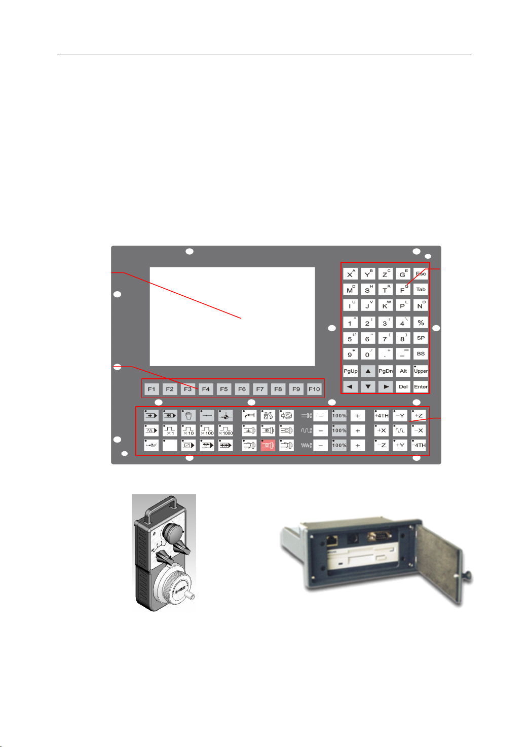
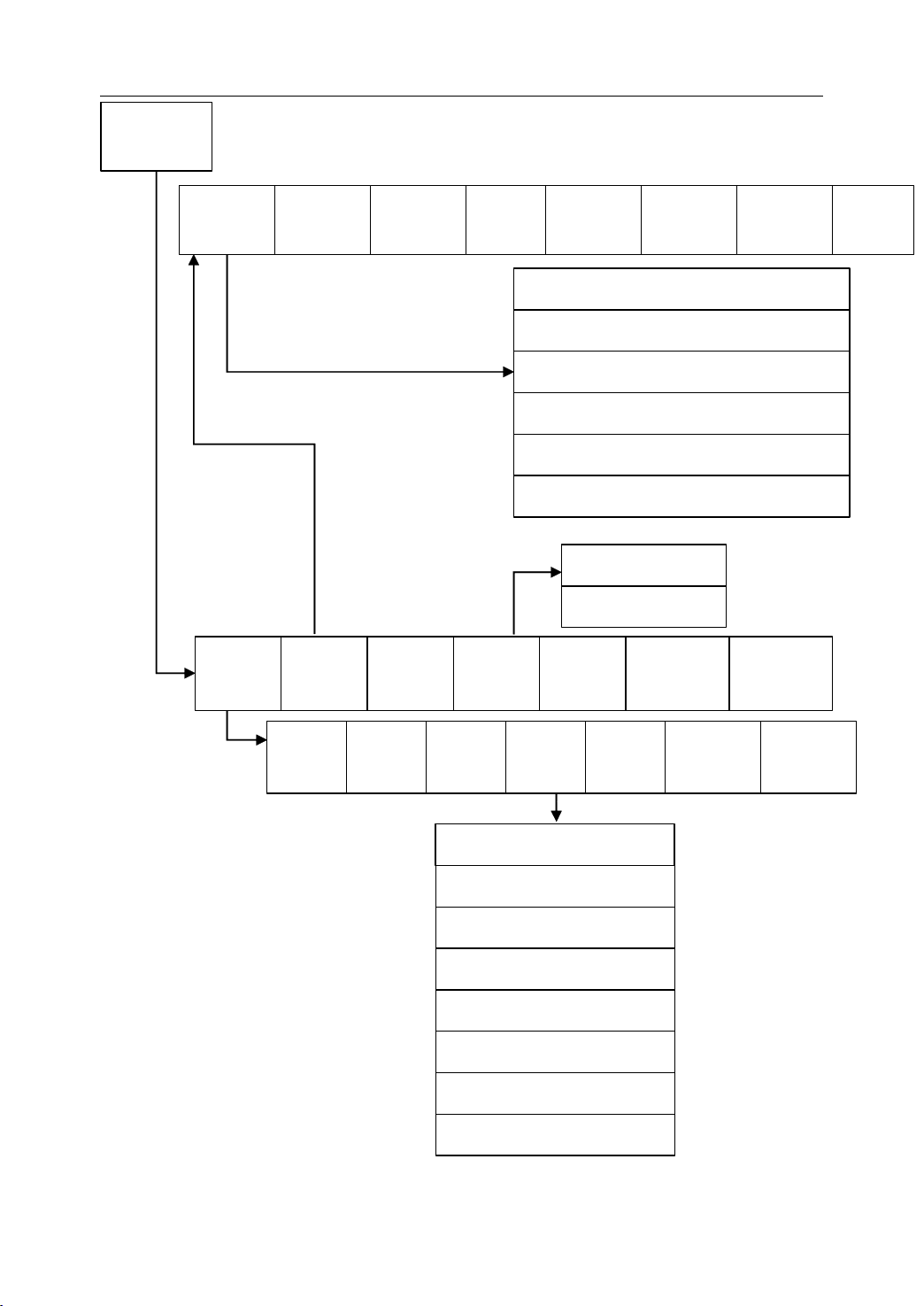
The user operates the milling either through the Machine Control Panel (Figure 1.1) or a
Hand Pendant (optional) ( Figure 1.2 ).AData Exchange Port (optional) (Figure 1.3) allows
the user to exchange data between the NCU and other computers through an Ethernet
connection, RS232 or floppy disk.APS/2 connector in the Data Exchange Port let the user
plug in a keyboard.
Layout
Layout
Layout
LCD
Screen
Soft keys
MDI
keyboard
Machine
control
keys
Figure 1 . 1 Machine Control Panel
Figure 1 . 2 Hand Pendant Figure 1 . 3 Data Exchange Port
1
1. Introduction
As it is shown in Figure 1.1, there four main areas on the Machine Control Panel : LCD
Screen, Soft keys, Manual Data Input (MDI) keyboard and Machine Control keys. These are
shown in detail below.
1.2
LCD
1.2
LCD
1.2
1.2 LCD
LCD Screen
Screen
Screen
Screen
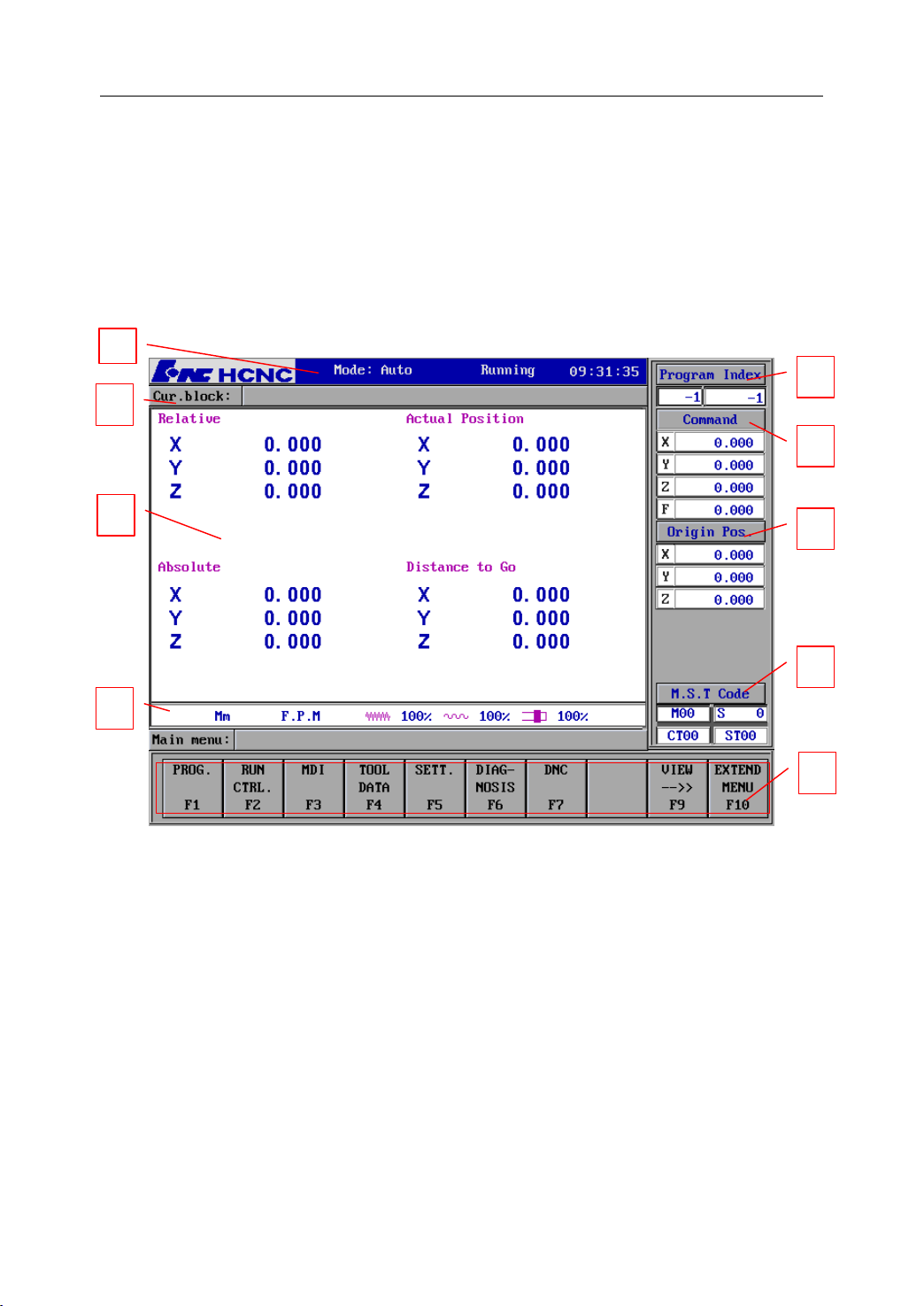
The LCD screen displays the machine
other information.
1
2
3
4
’
s status, the tool
’
s position, the program
’
s content and
5
6
7
8
9
Figure 1 . 4 LCD screen on the MCP
1) Machine information
Mode: automatic, single block, manual, incremental, reference, emergency stop.
Current status: running or error.
System time: current system time.
2) Current block information
It shows the current block in the program.
2

1. Introduction
3) View
Different views can be selected: graphical figure, numerical figure, overall positions,
and G code.
4) Diameter or Radius Programming, Metric/Inch, fe e drate per minute, fe e drate per
revolution, rapid traverse speed, feedrate override, spindle override.
5) Program Index
It shows the program name and the program block number
6) Position and Coordinate system
Different position value can be shown: the command position, actual position,
distance to go, trace error, or compensation.
Different coordinate systems can be selected: Machine coordinate system,
Workpiece coordinate system, and Relative coordinate system.
7) Origin Position
It shows the origin position of the workpiece in the machine coordinate system.
8) Auxiliary Information
It shows the M code, S code, and T code in the program.
9) Menu
It is corresponded to the soft keys on the machine control panel.
3
1. Introduction
1.3
Soft
1.3
Soft
1.3
1.3 Soft
Soft Keys
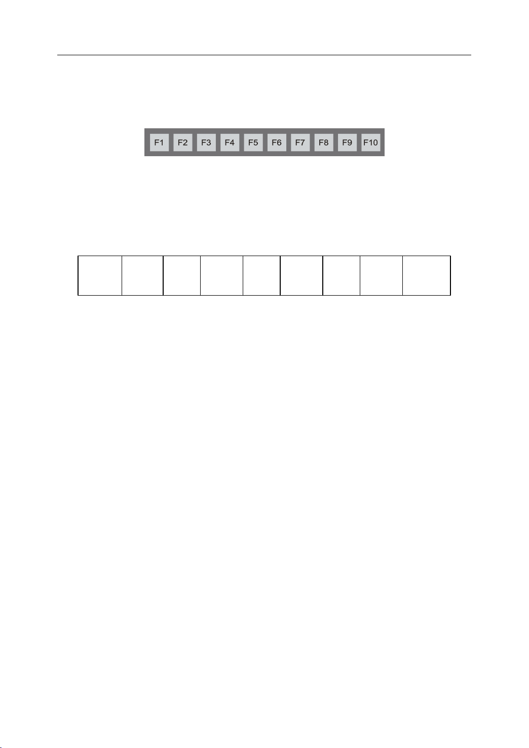
Beneath the LCD screen are the “ Soft keys ” from F1 to F10. Their functions change
depending on which main menu or submenu is active.
Keys
Keys
Keys
Figure 1 . 5 Soft keys on the machine control panel
1.3.1
1.3.1
1.3.1
1.3.1 M
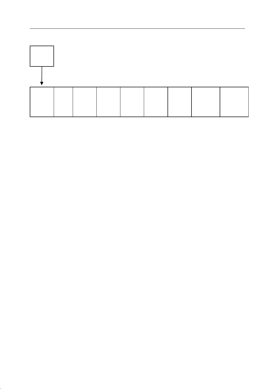
The following figure shows the main soft key menu. The keys display the function of that
key in the abbreviated notation.
PROG is the key that selects the programming function.
RUN selects the submenu which let the operator control the program running interactively.
MDI stands for Manual Data Input; it let the operator manually write G-code programs and
input data.
T OOL selects the tool submenu to let the operator choose tool offsets and parameters.
PROG
M
M
M ain
F1
ain
Menu
ain
Menu
ain Menu
Menu
RUN
F2
MDI
F3
TOOL
F4
Figure 1 . 6 Main Menu
SET
F 5
DIAG
DNC
F6
F 7
VIEW
F9
MORE
F10
SET picks the setting submenu letting the operator set axis and machine parameters.
DIAG selects the diagnos is submenu to alter alarms and machining statistics.
DNC stands for Direct Numerical Control, letting a program load from another computer.
VIEW selects one of several ways to view the screen display.
MORE picks an extended menu with more commands.
4
1. Introduction
1.3.2
1.3.2
1.3.2
1.3.2 PROG
PROG
PROG
PROG Submenu
PROG.
F1
OPEN
F1
EDIT
F2
Submenu
Submenu
Submenu
NEW
F3
SAVE
F4
Figure 1 . 7 PROG Submenu
VER
F 5
OPEN picks which program is to be run or edited.
EDIT allows the opened program to be edited.
NEW creates a new program while
SAVE
stores an edited program in memory.
PAUSE
F6
RE -
START
VIEW
-->>
F 7
F9
BACK
F10
VER verifies whether the opened program has correct syntax and tool path.
PAUSE temporarily halts a running program immediately .
RESTART resumes program running.
VIEW selects one of several ways to view the screen display.
BACK goes back to the main menu.
5
1. Introduction
1.3.3
1.3.3
1.3.3
1.3.3 RUN
RUN
RUN
RUN Submenu
Submenu
Submenu
Submenu
RUN
CTRL.
F2
PICK
BLOCK
F1
Figure 1 . 8 RUN Submenu
BP
SAVE
F 5
BP
LOAD
F6
From the red line F1
From the specified line F2
From the current line F3
VIEW
-->>
F9
BACK
F10
PICK BLOCK picks a block of the selected program and let the program run from this
block.
BP stands for break point, is used for operator to suspend and resume the machining
process.
BP
SAVE
allows the operator to save information at the current break point to memory.
B.P LOAD is to load the information at the saved breakpoint so that the program can be
executed at the break point.
VIEW selects one of several ways to view the screen display.
BACK goes back to the main menu.
6
1. Introduction
1.3.4
1.3.4
1.3.4
1.3.4 MDI
MDI
MDI
MDI Menu
Menu
Menu
Menu
The MDI submenu has five soft keys.
MDI
F 3
MDI
STOP
MDI
CLEAR
F1
F2
Figure 1 . 9 MDI menu
GOTO
B.P.
F7
MDI STOP stops the executing of the MDI command.
MDI CLEAR clears all the dimensional data manually input.
ALIGN
TOOL
BACK
F9
F10
GOTO BP let the tool go back to the breakpoint after an interactive intervention during
automatic machining.
ALIGN TOOL allows operator to re-align the tool
’
s dimension.
BACK goes back to the main menu.
7
1. Introduction
1.3.5
1.3.5
1.3.5
1.3.5 TOOL
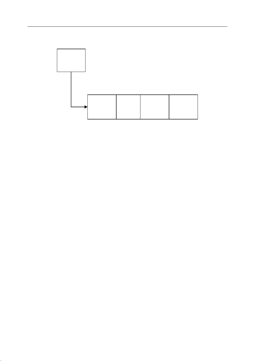
Magazine allows the user to group the tools to magazine.
DATA
group number.
TOOL
TOOL
TOOL Submenu
let the operator type the tool
Submenu
Submenu
Submenu
TOOL
Data
F4
Magazine
F1
Figure 1 . 10 TOOL Submenu
’
DATA
F2
s parameter such as length, radius, life expectancy and
VIEW
-->>
F9
BACKTO
MAIN
F10
VIEW selects one of several ways to view the screen display.
BACK goes back to the main menu.
8
1. Introduction
1.3.6
1.3.6
1.3.6
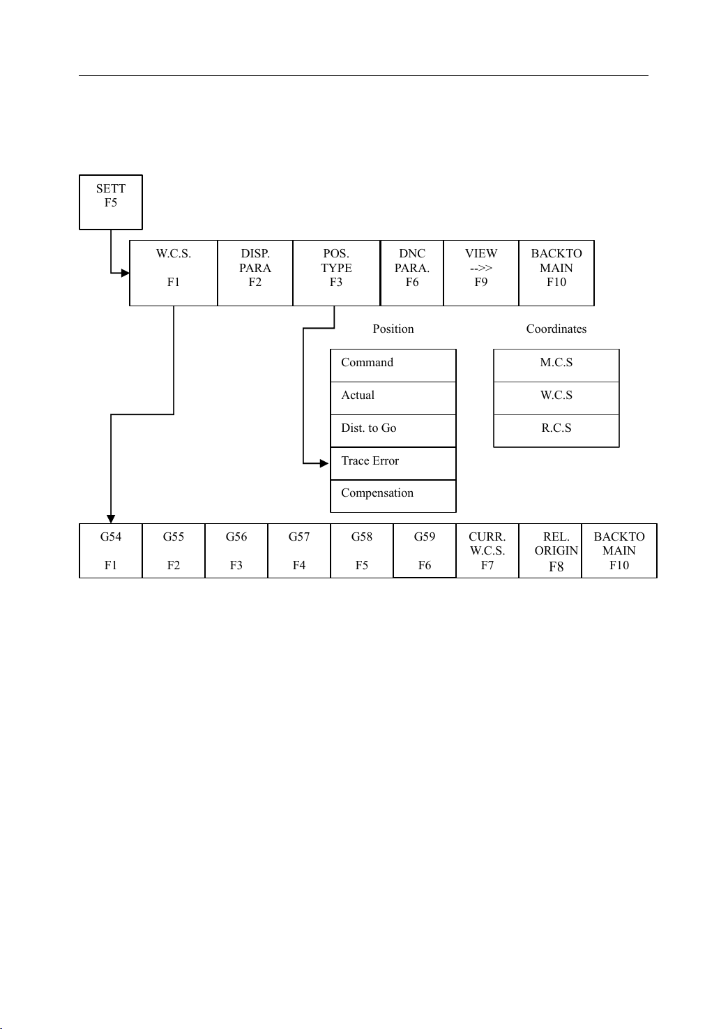
1.3.6 SET
SET
Submenu
SET
Submenu
SET Submenu
Submenu
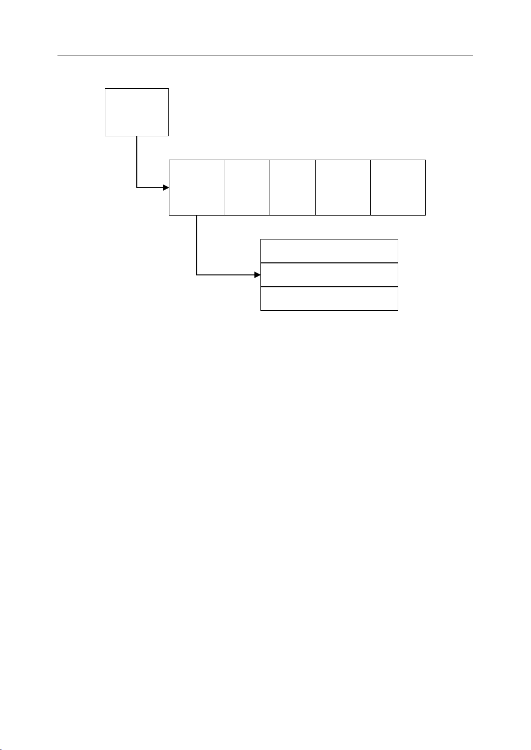
The SET submenu has six soft keys.
SETT
F 5
W.C.S.
F1
DISP.
PARA
F 2
POS.
TYPE
F3
Command
Actual
Dist. to Go
Trace Error
Compensation
Position
DNC
PARA.
F6
VIEW
-->>
F9
BACKTO
MAIN
F10
Coordinates
M.C.S
W.C.S
R.C.S
G54
F1
G55
F 2
G56
F 3
G57
F 4
Figure 1 .11SET Submenu
G58
F 5
G59
F 6
CURR.
W.C.S.
F 7
REL.
ORIGIN
F8
BACKTO
MAIN
WCS, stands for Workpiece Coordinate System, is used for user to define the origin position
of workpiece coordinates.
PART
SIZE let the operator provide the workpiece dimension for graphical.
POS TYPE is to select the position type to be displayed on the screen.
DNC
PARA
allows the user to change the communication parameters for RS232.
VIEW selects one of several ways to view the screen display.
BACK goes back to the main menu.
F10
9

1. Introduction
1.3.7
1.3.7
1.3.7
1.3.7 Diagnosis
The Diagnosis
STAT,
INIT let the operator set initial value for statistics.
ALARM is used to display the causes of an alarm if it occurs.
Diagnosis
Diagnosis
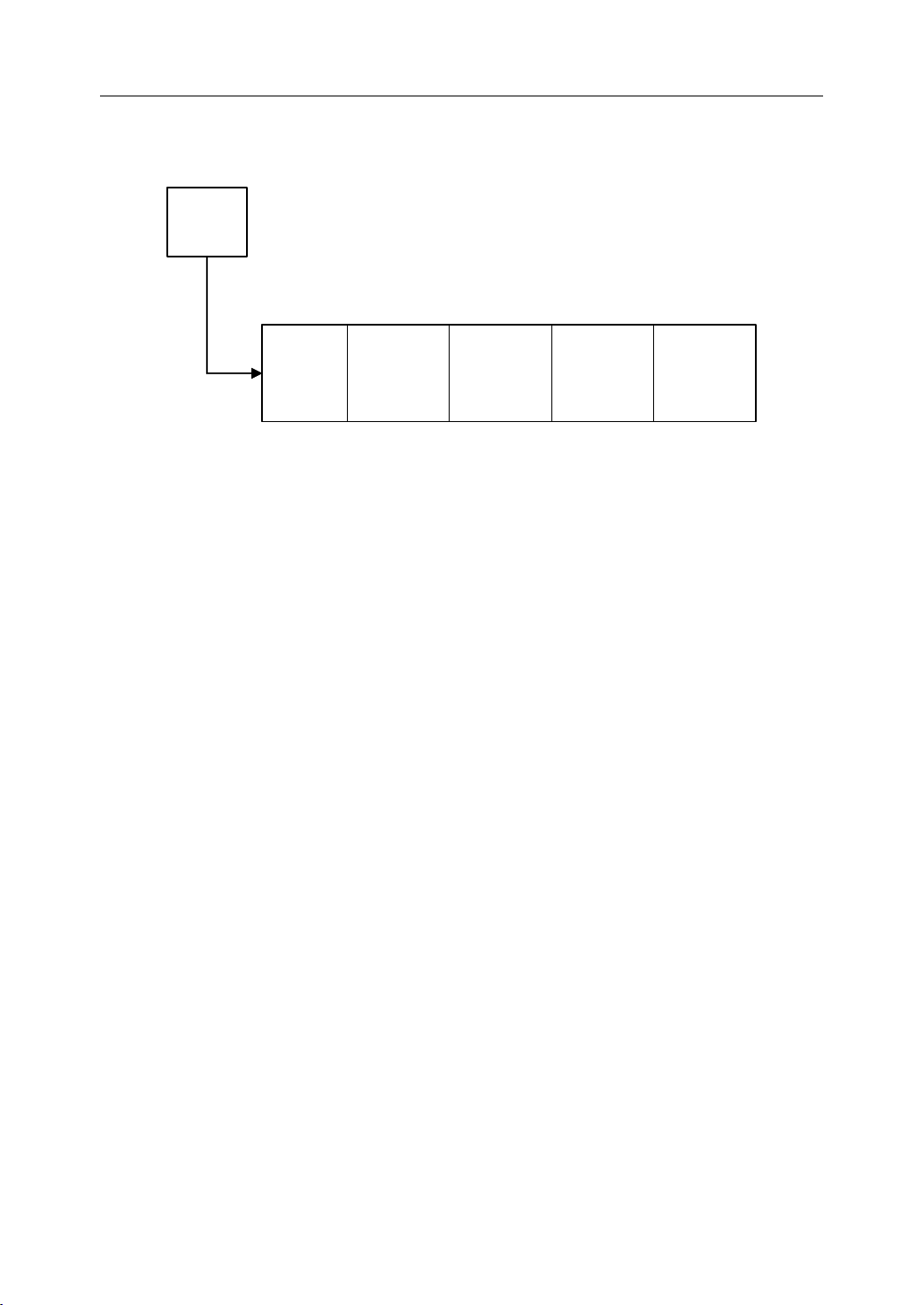
Diagnosis Submenu
Diagnosis
Diagnosis
Diagnosis or
DIAG
F6
allows the user to check the statistics information.
or
or
or DIAG
STAT
Submenu
Submenu
Submenu
DIAG
DIAG
DIAG submenu has six soft keys.
INIT
F 2
F3
ALARM
F6
Figure 1 . 12 Diagnosis Submenu
ALARM
List
F7
VIEW
-->>
F9
BACK
F10
ALARM LIST lists all the alarms happened before.
VIEW selects one of several ways to view the screen display.
BACK goes back to the main menu.
10

1. Introduction
1.3.8
1.3.8
1.3.8
1.3.8 EXTEND
There four more soft keys under EXTEND MENU submenu.
PLC, stands for Programmable Logic Circuits, and allows the user to do PLC operations.
PARA
ABOUT let the user check the software’s version information.
REG, stands for register, let the operator register the software.
VIEW selects one of several ways to view the screen display.
BACK goes back to the main menu.
EXTEND
EXTEND
EXTEND MENU
is used to set/change parameters.
MENU
MENU
MENU Submenu
Submenu
Submenu
Submenu
11
EXTEND
MENU
F10
1. Introduction
PARAM.
INDEX
F1
PLC
F1
PASSW.
CHANGE
F2
PARA.
F3
PASSW.
INPUT
ABOUT
F 4
LOAD
DEFAULT
F 3
F5
REGI.
F6
BACKUP
PREVAL
F 6
Machine Parameters F1
Axis Parameters F2
Servo Parameters F3
Axis Compensation Parameters F4
PMC User Parameters F5
Trans-quadrant Compensation F6
System F1
Optional F2
BACK,
EDIT.
F 8
BACKUP
PARAM.
F7
VIEW
-->>
F9
LOAD
PARAM.
F8
BACK
F10
B ack to
MAIN
F10
LOAD
Modify
F1
F2
Figure 1 . 13 MORE Submenu
I/O
F 3
X:[Mac->PMC] F1
Y:[PMC->Mac] F2
12
Watch
F4
F:[CNC->PMC] F3
G:[PMC->CNC] F4
R:[REGIN PMC] F5
P:[Parameter] F6
B:[BLIFFER] F8
Cancel F9
BACK
VIEW
UP
F 7
-->>
F9
BACK
F10
1. Introduction
1.4
Manual
1.4
Manual
1.4
1.4 Manual
Manual Data
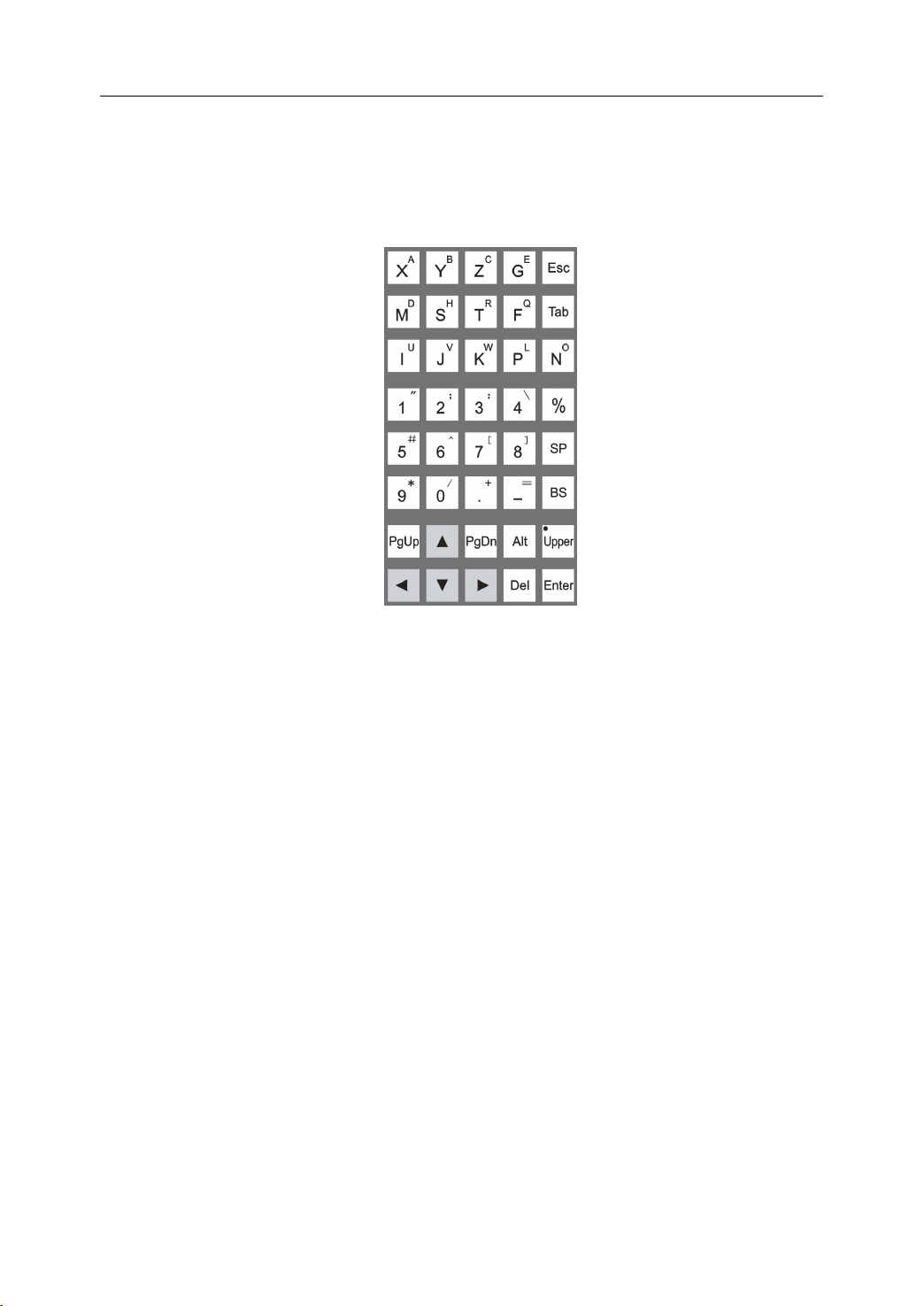
On the right side of the LCD screen is the Manual Data Input keyboard. These keys are used
for editing a program, as well as changing or viewing parameters.
Data
Data
Data Input
Input
Input
Input Keyboard
Keyboard
Keyboard
Keyboard
Figure 1 . 14 Manual Data Input keyboard on the machine control panel
13
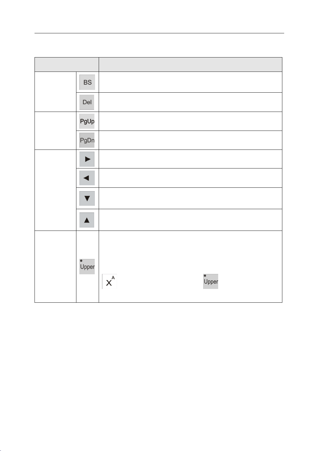
The following table is the description of the MDI keys.
Table 1 1 Description of MDI Keyboard
1. Introduction
KEY
KEY
KEY
KEY DESCRIPTION
DESCRIPTION
DESCRIPTION
DESCRIPTION
Backspace
Backspace
Backspace
Backspace key deletes the character in front of the cursor .
Delete keys
Delete
Delete
Delete
Delete key deletes the character at the cursor
PageUp
PageUp
PageUp
PageUp key moves the page one screen up
Page change
keys
PageDown
PageDown
PageDown
PageDown key moves the page one screen down.
Right
key:
Right
key:
Right
Right key:
key: moves the cursor to the right, selects a soft key to the
right or selects a column to the right.
Left
key:
Left
key:
Left
Left key:
key: moves the cursor to the left, selects a soft key to the
left or selects a column to the left.
Cursor keys
Down
Down
Down
Down key:
key:
key:
key: moves the cursor down, selects a soft key on the
bottom or selects a row on the bottom.
Up
key:
Up
key:
Up
Up key:
key: moves the cursor up, selects a soft key on the top or
selects a row on the top.
The Shift Up key toggles the status of double-character keys o n
the manual data input keyboard. The LED light in the upper-left
corner indicates whether the upper character is selected. When
Shift Up key
the LED light is on, the upper character is selected, otherwise the
lower character will be input. For example, “ X ” will be input if
is pressed when LED light of is off, while “ A ” will
be input when the LED light is on.
14
1. Introduction
1.5
Machine
1.5
Machine
1.5
1.5 Machine
Machine Control
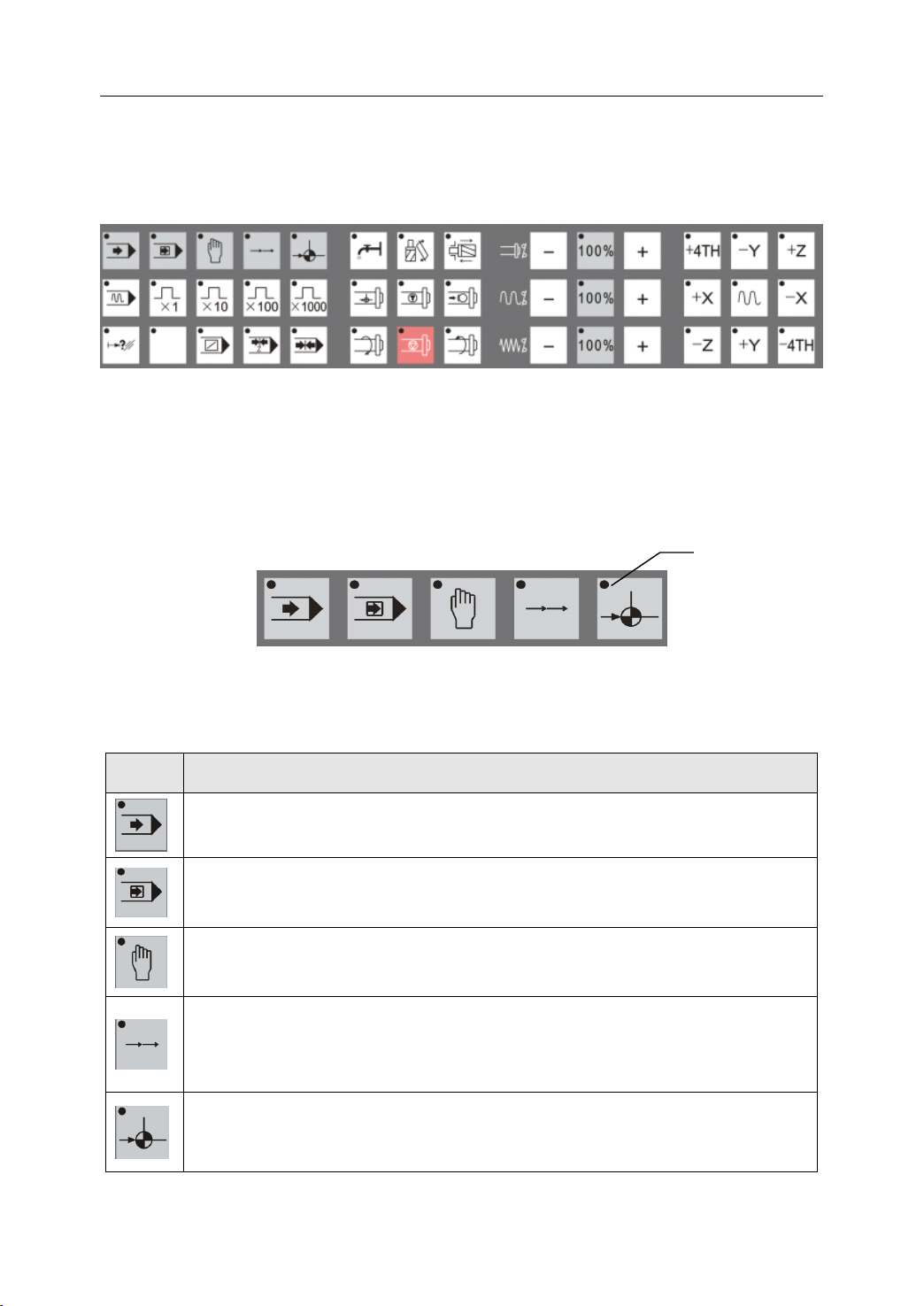
At the bottom of the machine control panel are the Machine Control keys. These keys operate
the machine directly.
Figure 1 . 15 Machine control keys on the machine control panel
Control
Control
Control Keys
Keys
Keys
Keys
1.5.1
1.5.1
1.5.1
1.5.1 Mode
T he following figure show s the five switches that select the operation mode of the machine.
Note that the small LED “ activation ” light on the upper left of each key indicates in which mode
the machine is working.
The following table is the description of the mode selection keys.
Mode
Mode
Mode Selection
KEY
KEY
KEY
KEY DESCRIPTION
Selection
Selection
Selection Switches
Table 1 2 Description of Mode Selection Keys
DESCRIPTION
DESCRIPTION
DESCRIPTION
Automatic
Automatic
Automatic
Automatic (AUTO)
AUTO mode, workpiece can be machined automatically from a program.
Single
Single
Single
Single Block
In SBL mode, a program can be run block by block.
Manual
Manual
Manual
Manual (MAN)
“ jog ” mode. In manual mode, any axis of the tool can be manually controlled.
Block
Block
Block (SBL)
(MAN)
(MAN)
(MAN) mode
Switches
Switches
Switches
Figure 1 . 16 Mode Selection Switches
(AUTO)
(AUTO)
(AUTO) mode
(SBL)
(SBL)
(SBL) mode
mode
key:
mode
key:
mode key:
key: Pressing this key switches to Auto mode. In
mode
key:
mode
key:
mode key:
key: Pressing this key switches to “ SBL ” mode.
mode
key:
mode
key:
mode key:
key: Pressing this key switches to manual operation or
Activation
light
Incremental
Incremental
Incremental
Incremental (INC)
mode. In INC mode, the tool can be moved a number of steps along any axis
by either the Axis keys or the hand wheel (Manual Pulse Generator). The
number of steps depends on which of the multiple-step keys is selected.
Reference
Reference
Reference
Reference (REF)
In Reference mode, each motion axis can home exactly on its reference
position.
(INC)
(INC)
(INC) mode
(REF)
(REF)
(REF) mode
mode
mode
mode key:
mode
key:
mode
key:
mode key:
key: Pressing this key switches to “ INC ” operation
key:
key:
key: Pressing this key switches to “ Reference ” mode.
15
1. Introduction
1.5.2
1.5.2
1.5.2
1.5.2 V erify
Verify key shown in the following figure is used in conjunction with the Automatic Mode
key.
When the V erify key is activated, a program runs at a higher speed than normal machining.
The operator can run a program quickly, but the operator should be sure the program
performs the proper function.
1.5.3
1.5.3
1.5.3
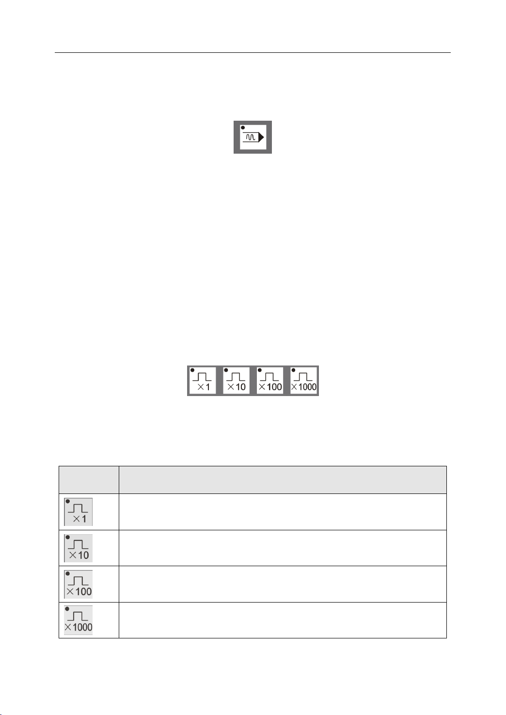
1.5.3 Multiple
A
each rotational axis. The following figure are the four multiple step selection keys used
during incremental operation. Again, the LED light on the key’s upper-left corner indicates
the selected multiple step . First the INC key is pushed to set the Incremental Mode, then the
Verify
Verify
Verify Key
Multiple
Multiple
Multiple Step
step is equal to one micrometer (1 µ m) for each linear axis (X,
Key
Key
Key
Step
Step
Step Keys
Keys
Keys
Keys
Figure 1 . 17 Verify Key
Y,
Z) and 0.001 degrees for
desired number of multiple steps is pressed , and finally the desired Axis key is pressed.
Figure 1 . 18 Multiple Step Keys
The following table shows the description of multiple step keys.
Table 1 3 Description of Multiple Step Keys
KEY
KEY
KEY
KEY DESCRIPTION
DESCRIPTION
DESCRIPTION
DESCRIPTION
Each key push moves that axis one step
Each key push moves that axis 10 steps
Each key push moves that axis 100 steps
Each key push moves that axis 1000 steps
16

1. Introduction
1.5.4
1.5.4
1.5.4
1.5.4 Other
The five keys below are other keys that control various machining functions.
The following table is the description of other control keys.
Other
Other
Other Control
KEY
KEY
KEY
KEY DESCRIPTION
Control
Control
Control Keys
Table 1 4 Description of Other Control Keys
DESCRIPTION
DESCRIPTION
DESCRIPTION
Over-travel
Over-travel
Over-travel
Over-travel release
occurs, press this key until the system is reset, then move the axis out of
over-travel.
Not used
Block
Bypass
Block
Bypass
Block
Block Bypass
Bypass key:
with a “ / ” character .
Keys
Keys
Keys
Figure 1 . 19 Other Control Keys
release
release
release key:
key:
key:
key: Activating this key bypasses program blocks that start
key:
key:
key: When mechanical over-travel on any axis
Program
Program
Program
Program Stop
function, stopping the program at a desired block.
Machine
Machine
Machine
Machine Lock
spindle, the tool turret change or any axis; it is used for system testing .
Stop
key:
Stop
key:
Stop key:
key: Activating this key enables the M01 G-code stop
Lock
key:
Lock
key:
Lock key:
key: Activating this key prevents any motion from the
17
1. Introduction
1.5.5
1.5.5
1.5.5
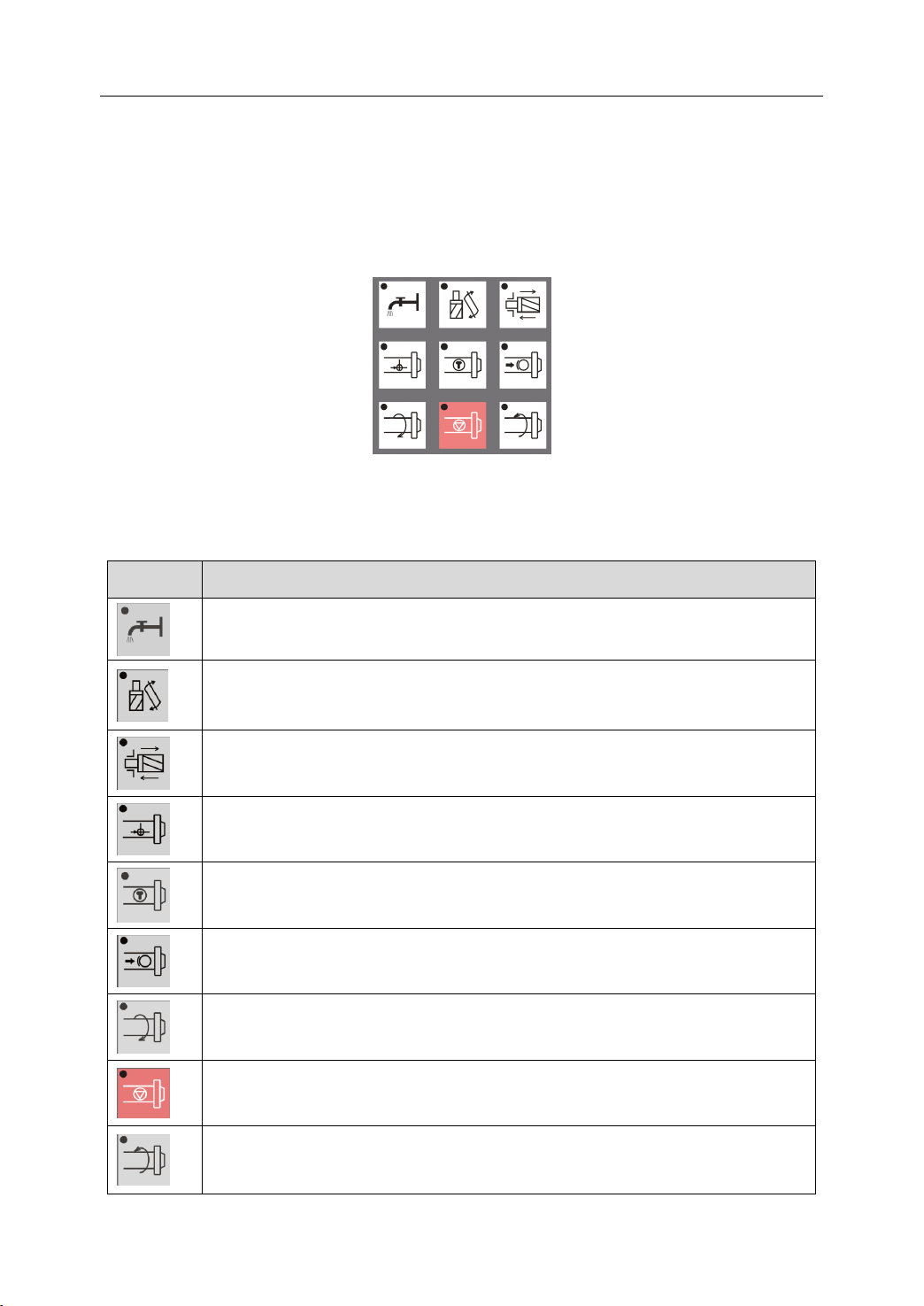
1.5.5 Spindle
These nine keys are usually available in Manual mode. They control spindle, turret too l
selection , and coolant function . These functions are activated only when no program is
running.
Details of the keys are shown in the following table:
Spindle
Spindle
Spindle and
KEY
KEY
KEY
KEY DESCRIPTION
and
Auxiliary
and
Auxiliary
and Auxiliary
Auxiliary Operation
Figure 1 . 20 Spindle and Auxiliary Operation Keys
Table 1 5 Description of Spindle and Auxiliary Keys
DESCRIPTION
DESCRIPTION
DESCRIPTION
Coolant
Coolant
Coolant
Coolant Switch
Switch
Switch
Switch key:
Operation
Operation
Operation K
key:
key:
key: This key opens or closes the coolant flow
K
K
K eys
eys
eys
eys
Tool
exchange
Tool
exchange
Tool
Tool exchange
exchange enable
exchange operation.
Tool
lock/unlock:
Tool
lock/unlock:
Tool
Tool lock/unlock:
lock/unlock: After pressing this key, the tool will be release if it is
locked before and will be locked if it is to be replaced in.
Spindle
Spindle
Spindle
Spindle orientation:
position that can align the spindle to its seat.
Spindle
Spindle
Spindle
Spindle jog
press.
Spindle
Spindle
Spindle
Spindle brake:
Spindle
Spindle
Spindle
Spindle Clockwise
in the clockwise direction (top of workpiece moves toward operator).
Spindle
Spindle
Spindle
Spindle Stop
Spindle
Spindle
Spindle
Spindle Counter-clockwise
rotation in the counter-clockwise direction (top of workpiece moves away
from operator).
orientation:
orientation:
orientation: Pressing this key to let the spindle approach a certain
jog
jog
jog key:
brake:
brake:
brake: Press ing down this key will brake the spindle.
Clockwise
Clockwise
Clockwise Rotation
Stop
Stop
Stop key:
Counter-clockwise
Counter-clockwise
Counter-clockwise Rotation
enable
enable
enable key:
key:
key:
key: This key rotates the spindle for a short time after each
key:
key:
key: Stop the spindle rotation by pressing this key.
key:
key:
key: Press this key to enable or disable tool
Rotation
Rotation
Rotation key:
key:
key:
key: Pressing this key begins spindle rotation
Rotation
Rotation
Rotation key:
18
key:
key:
key: Pressing this key begins spindle
1. Introduction
1.5.6
1.5.6
1.5.6
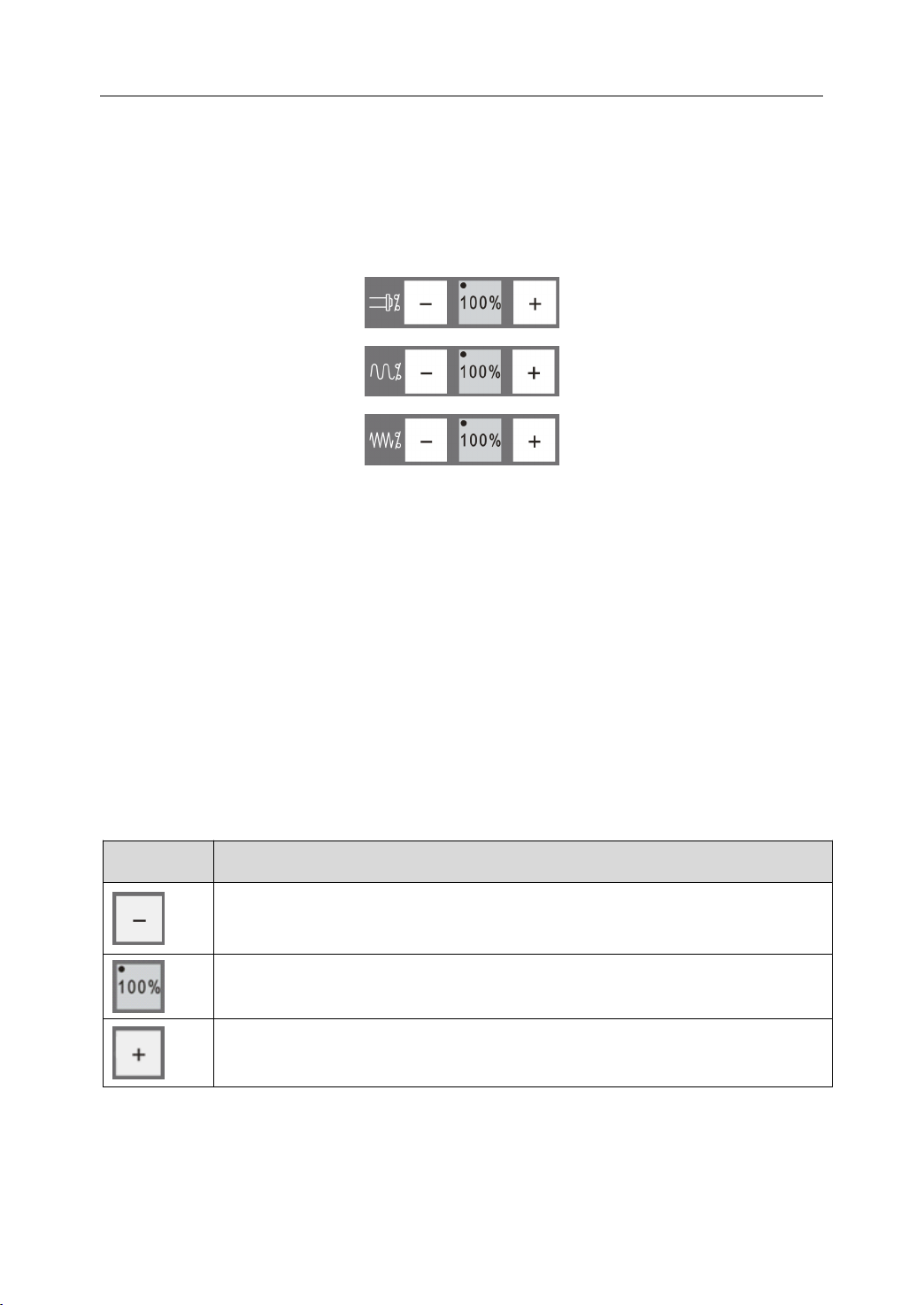
1.5.6 Speed
By pressing these keys , the spindle speed, rapid traverse speed and feed rate (machining
speed) can be adjusted. The first row controls the spindle speed, the second row controls the
rapid traverse speed and the bottom row controls feed rate.
These keys work by adjusting the speed relative to a “ base ” speed. Different modes
(Automatic, Single Block and Manual) may have different base speeds. The base speed is
set by the G-code program or the parameter.
For each row, pressing the center key sets the speed at 100% of the base speed; the LED
Speed
Speed
Speed Adjustment
Adjustment
Adjustment
Adjustment K
Figure 1 . 21 Speed Adjustment Keys
K
K
K eys
eys
eys
eys
light in the key’s upper-left corner is lit to signify that the machine is running at 100 percent
of the base speed. Pressing the minus (-) key, decreases the base speed by a fixed percent;
pressing the plus (+) key, increases the base speed by a fixed percent. Below is an example
where the speeds are changed by 2%:
Table 1 6 Description of Speed Adjustment Keys
KEY
KEY
KEY
KEY DESCRIPTION
DESCRIPTION
DESCRIPTION
DESCRIPTION
Pressing this key decreases the speed 2% for each press. The current speed
or rate is displayed on the LCD screen.
Once this key is pressed, the override ratio is set to 100%. The LED light
indicates that the current speed is the base speed.
Pressing this key increases the speed 2% for each press. The current speed
or rate is displayed on the LCD screen.
19
1. Introduction
1.5.7
1.5.7
1.5.7
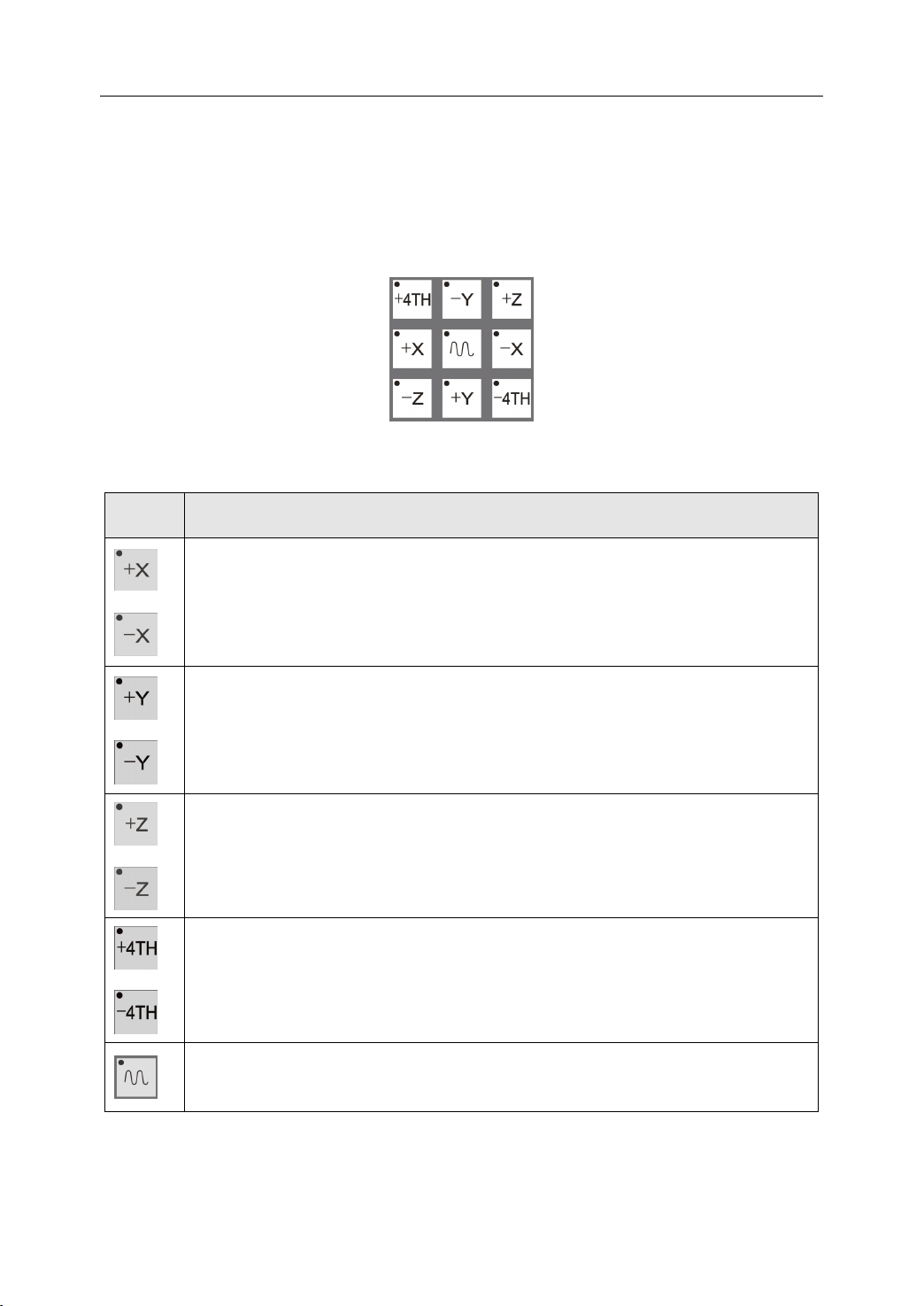
1.5.7 Axis
These nine keys are to select the desired axis and the direction of motion in various modes.
These keys only function in Manual Mode, INC Mode and Reference Mode. The LED light
in the upper-left corner specifies which axis or direction is selected.
Axis
Operation
Axis
Axis Operation
KEY
KEY
KEY
KEY DESCRIPTION
Operation
Operation K
Table 1 7 Description of Axis Operation Keys
DESCRIPTION
DESCRIPTION
DESCRIPTION
In INC mode or Manual Mode, the tool moves the X axis in the positive
direction while +X is pressed , and in the negative direction while – X is
pressed. In Reference mode, pressing the +X key homes the X axis (finds the
machine reference on the X axis).
K
eys
K
eys
K eys
eys
Figure 1 . 22 Axis Operation Keys
In INC mode or Manual Mode, the tool moves the Y axis in the positive direction
while +Y is pressed , and in the negative direction while – Y is pressed. In
Reference mode, pressing the +Y key homes the Y axis (finds the machine
reference on the Y axis).
In INC mode or Manual Mode, the tool moves the Z axis in the positive
direction while +Z is pressed , and in the negative direction while – Z is
pressed. In Reference mode, pressing the +Z key homes the Z axis (finds
machine reference on the Z axis).
The 4TH axis is only valid for servo-driven spindle mills. In INC mode or
Manual Mode, the spindle moves in the positive direction while +4TH is
pressed and in the negative direction while – 4TH is pressed. In Reference
mode, pressing the +4TH key homes the spindle (finds the spindle reference).
This key speeds up tool motion in Manual mode. It must be pressed in
conjunction with one of the Axis keys.
20
1.6
Other
1.6
Other
1.6
1.6 Other
Other Control
Control
Control
Control Keys
Keys
Keys
Keys
1. Introduction
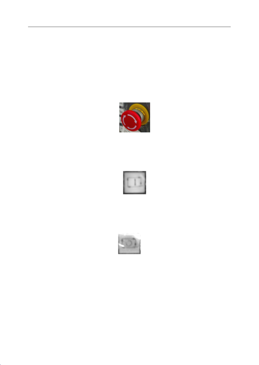
1.6.1
1.6.1
1.6.1
1.6.1 Emergency
An emergency stop button is on MCP to deal with abnormal situations. Pushing down the
button stops the machine from any further motion and sets the electronic to brake the motor
axes and spindle. Pulling upon this emergency button resets the software system and the
machine can operate again under computer or manual control.
1.6.2
1.6.2
1.6.2
1.6.2 Cycle
A
Emergency
Emergency
Emergency Stop
Cycle
Cycle
Cycle Run
green “ Cycle Run ” button starts the automatic machining process.
Run
Run
Run
Stop
Stop
Stop
Figure 1 . 23 Emergency Stop button
Figure 1 . 24 Cycle Run button
1.6.3
1.6.3
1.6.3
1.6.3 Feed
A
Feed
Feed
Feed Hold
red “ Feed Hold ” button pauses machining under computer control.
Hold
Hold
Hold
F igure 1 . 25 Feed Hold button
21
1.7
Auxiliary
1.7
Auxiliary
1.7
1.7 Auxiliary
Auxiliary Devices
Devices
Devices
Devices
1. Introduction
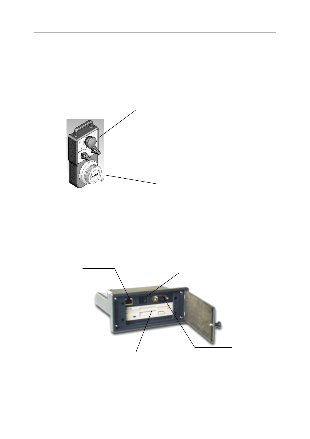
1.7.1
1.7.1
1.7.1
1.7.1 Hand
Usually a handwheel, an emergency stop button and override switches are assembled on a
Hand Pendant.
1.7.2
1.7.2
1.7.2
1.7.2 Data
Data exchange port is for inputting or outputting program data to the NC unit. LAN, RS232
Hand
Hand
Hand Pendant
Data
Data
Data Exchange
Pendant
Pendant
Pendant
Exchange
Exchange
Exchange Port
Emergency Stop
Manual Pulse Generator
Figure 1 . 26 Hand Pendant
Port
Port
Port
are used for communication with other computer via cable. Floppy drive is for the f loppy
disk. PC keyboard can be plugged in to operate the controller.
LAN
Floppy Drive
Figure 1 . 27 Data Exchange Port
22
PC Keyboard
RS232
 Loading...