

Page 1

HNC-21/22
HNC-21/22
HNC-21/22
HNC-21/22 CNC
CNC
CNC
CNC Device
Device
Device
Device
Connection
Connection
Connection
Connection Manual
Manual
Manual
Manual
Wuhan
Wuhan
Wuhan
Wuhan Huazhong
Huazhong
Huazhong
Huazhong Numerical
V
2.0
V
2.0
V
V 2.0
2.0
20
10/11
20
10/11
20
20 10/11
10/11
Numerical
Numerical
Numerical Control
Control
Control
Control Co.
Co.
Co.
Co. Ltd
Ltd
Ltd
Ltd
Page 2

Page 3

HNC-21/22 Connection Manual
Preface
Preface
Preface
Preface
This connection manual is for HNC-21/22 unit. It is recommended that the operator
read this manual before operating the machine.
The organization of this manual:
(1) Precaution
(2) Connection
(3) Parameters
(4) Commissioning
(5) Typical Design
(6) Appendix
i
Page 4

HNC-21/22 Connection Manual
Introduction
Introduction
Introduction
Introduction
1.
HNC-
1.
1.
1. HNC-
HNC-21/22 (HNC- 21 /TD, HNC- 21 /M D, HNC-22/TD, HNC-22/MD ) possesses the
advanced open-structure, built-in industrial control computer, and high-performance
32-bit CPU. T here are 8.4’(HNC-21)/10.4’(HNC-22) LCD and standard panel for
machine tool engineering. It integrates feed axis interface, spindle interface,
handwheel unit interface, and built-in PLC ( Programmable Logic Circuits ) interface
as a whole. It supports the program storage form, and also supports the program
exchange through USB , DNC (Direct Numerical Control ) , Ethernet. According to its
high performance, compact structure, being easy to use, reliability, and reasonable
price, the Device is mainly suitable for numerical control of turning machines, milling
machines, and machining centers .
- Maximum coordinate axes: 6;
21/22
HNC-
21/22
HNC- 21/22
21/22
- Compatible with various pulsed AC servo drives, step motor drives;
- Standard panel for machine tool engineering is used . N o PLC input/output
interfaces are taken up. The color of machine control panel and the name of key
on the panel can be customized for different users.
- T here are 40 bit (extended to 60 bit) input interfaces , 32 bit optical isolated
output interfaces (extended to 48 bit), handwheel unit interface, analog spindle
control interface and spindle encoder interface.
- With 8.4’(HNC-21)/10.4’(HNC-22) LCD (the resolution is 640 × 480 ) , it is easy to
display the alarm message and simulation of tool - path.
- The program is written in ISO G code, compatible with any common CAD/CAM.
It can implement the linear interpolation, the circular interpolation, the helical
interpolation, the canned cycle, the rotation, the scale, the mirror image, the tool
compensation, the macro-program , etc.
- Machining a specified segment incrementally is especially suitable for machining
the compl icate moulds .
- The breakpoint can be saved and resumed , which provides the convenience and
safety for customers.
ii
Page 5

HNC-21/22 Connection Manual
- T he backlash and the uni-/ bi - directional pitch error compensation can improve
the machining precision effectively.
- It can save G code program up to 2GB.
- The data can be exchanged through RS232 or Ethernet .
- Flash RAM: 2GB is used to save the program (no cell is required).
- RAM: 32MB is used as a buffer for machining program .
Note: the default configuration of Flash RAM and RAM would not be notified
once again, if the size is increased.
- The dimension of device is 420 × 310 ×
2.
DNC
unit
2.
2.
2. DNC
DNC
DNC unit
(optional)
unit
(optional)
unit (optional)
(optional)
11
0 mm ( W × H × D).
DNC unit is a unit for interface switcher, which are DNC (RS-232) interface, PC
keyboard (PS2) interface, Ethernet interface .
Since there are DNC (RS-232) interface, PC keyboard (PS2) interface, and USB
interface on HNC-21, DNC unit is mainly used on HNC-22.
3.
Handwheel
3.
Handwheel
3.
3. Handwheel
Handwheel unit
unit
(optional)
unit
(optional)
unit (optional)
(optional)
- S tandard four -wire m anual pulse generator
- Four-axis switch
- Three kinds of magnification switch
- Emergency stop button
- Handwheel enabl e button
- Pilot lamps
4.
I/O
4.
I/O
4.
4. I/O
I/O Terminal
Terminal
Terminal
Terminal Board
Board
Board
Board
The I/O terminal board is connect ed to the optically isolated PLC inputs and outputs
through cables to facilitate wiring, commissioning and maintenance for the control
cabinet.
- 20-bit PLC inputs or 16-bit PLC outputs
- P ilot lamp on e ach input or output interface
- Both NPN and PNP interfaces are provided .
iii
Page 6
HNC-21/22 Connection Manual
5.
Relay
5.
Relay
5.
5. Relay
Relay Terminal
Terminal
Terminal
Terminal Board
Board
Board
Board (optional)
(optional)
(optional)
(optional)
I t is connect ed to the optically isolated PLC outputs through cables to facilitate wiring,
commissioning and maintenance for the control cabinet.
- 8 -bit PLC direct terminal out puts + 8-bit relay normally open contact point
outputs
- Two independent double-pole relays. Both normally open + normally closed
contact points are supported.
- P ilot lamp on e ach input or output interface .
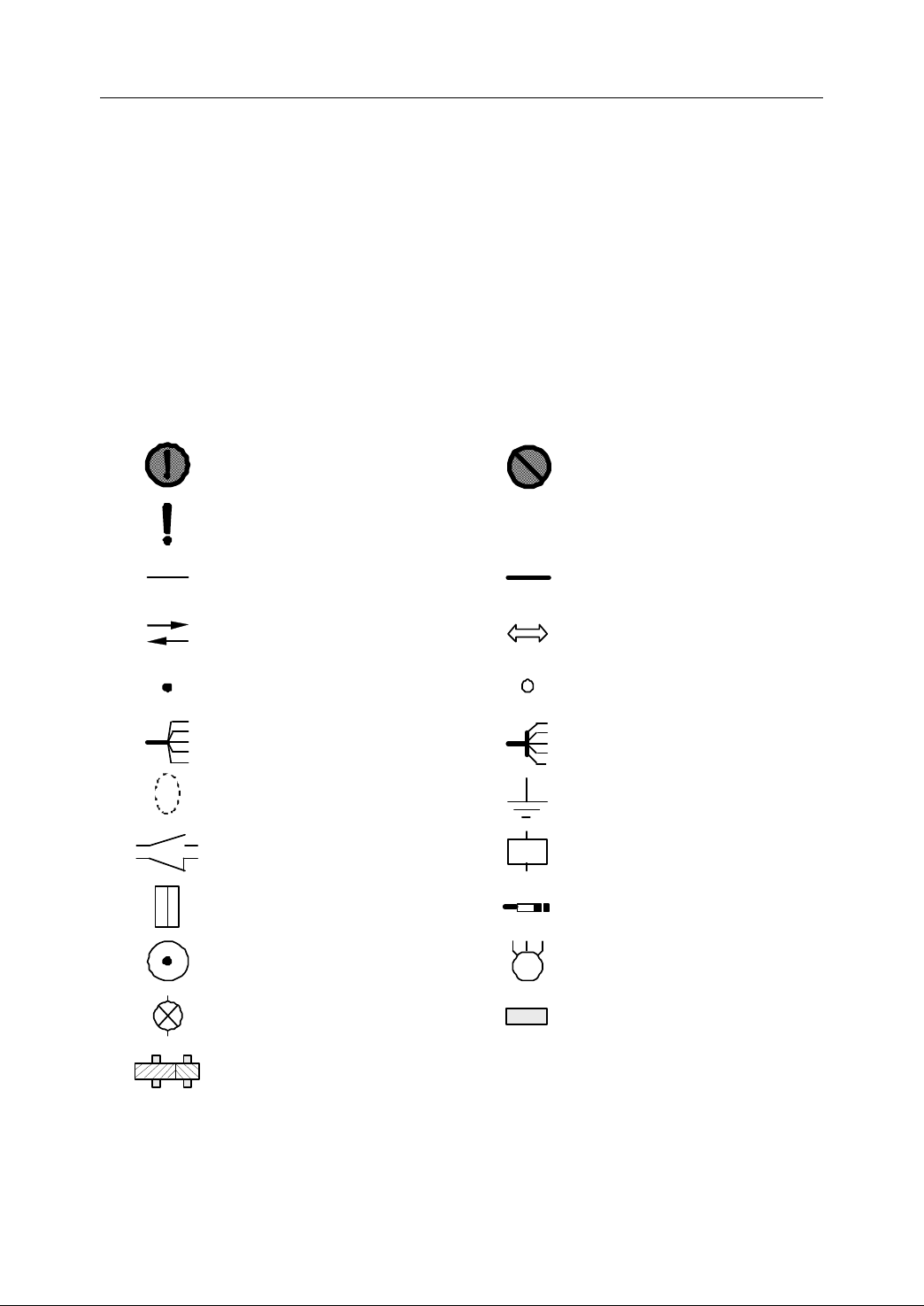
II 图形符号系统 第 1 页 共 1 页
6.
Safety
6.
Safety
6.
6. Safety
Safety Placard
Placard
Placard
Placard
: m ust do.
; especially important
: line or boundary
: signal direction
: point connected
: cable bunched/diverged
: shielding layer
: passive NO and NC
: plug and socket
: encoder
【 】
: s h all not be done.
: default, initia l setting
: a set of cable
: exchange
: terminal
: cable bunched/diverged
: grounding
: coil
: transducer
: motor
: pilot lamp
: gearbox
iv
: mechanical linkage
Page 7

HNC-21/22 Connection Manual
Table
Table
Table
Table of
Preface .................................................................................................................................................................... i
Introduction ............................................................................................................................................................ ii
Table of Contents
1 Precaution .................................................................................................................................................... 1
1.1 Safety ...................................................................................................................... 2
1.2 Unpacking and Checking ........................................................................................ 6
1.3 Dimensions ............................................................................................................. 7
1.4 Installation .............................................................................................................. 8
1.5 Environmental Requirement ................................................................................. 10
2 Connection .................................................................................................................................................
2.1 Total Connection Diagram .................................................................................... 12
2.2 Interface ................................................................................................................ 13
2.3 Power Supply Connection .................................................................................... 17
2.4 Connection to DNC unit ....................................................................................... 20
2.5 Connection to Computer ....................................................................................... 21
2.6 PLC I/O Interface ................................................................................................. 24
2.7 Connection to Handwheel Unit ............................................................................. 36
of
Contents
of
Contents
of Contents
Contents
..................................................................................................................................................
1.1.1 Transportation and Storage ........................................................................ 2
1.1.2 Installation ..................................................................................................... 2
1.1.3 Wiring ............................................................................................................. 3
1.1.4 Commissioning ............................................................................................. 3
1.1.5 Operation ....................................................................................................... 4
1.1.6 Maintenance ................................................................................................. 4
1.1.7 Waste Treatment .......................................................................................... 5
1.1.8 General Instructions ..................................................................................... 5
1.2.1 List .................................................................................................................. 6
1.2.2 Product Type ................................................................................................. 6
1.5.1 Weather Condition ..................................................................................... 10
1.5.2 Elevation ...................................................................................................... 10
1.5.3 Transportation and Storage ...................................................................... 10
1.5.4 Mechanical Environment ........................................................................... 10
1.5.5 Environmental Pollution ............................................................................ 10
2.2.1 NC Device ................................................................................................... 13
2.2.2 DNC unit (optional) .................................................................................... 14
2.2.3 Handwheel unit (optional) ......................................................................... 14
2.2.4 I/O Terminal Boards (optional) ................................................................. 15
2.3.1 General Requirement ................................................................................ 17
2.3.2 Grounding .................................................................................................... 18
2.5.1 RS232 Interface ......................................................................................... 21
2.5.2 Ethernet Interface ....................................................................................... 21
2.6.1 Input interface ............................................................................................. 24
2.6.2 Output interface .......................................................................................... 27
2.6.3 Direct Connection to NC device ............................................................... 32
2.6.4 Connection to NC device through I/O terminal board ........................... 33
2.6.5 Description of PLC Address ..................................................................... 34
2.7.1 Handwheel Interface .................................................................................. 36
2.7.2 Connection to Standard Handwheel Unit ............................................... 37
v
11
v
Page 8

HNC-21/22 Connection Manual
2.7.3 Connection to Customized Handwheel Unit .......................................... 38
2.8 Connection to Spindle device ............................................................................... 39
2.8.1 Relevant Interfaces .................................................................................... 39
2.8.2 Spindle Start and Spindle Stop ................................................................ 40
2.8.3 Spindle Speed Control .............................................................................. 41
2.8.4 Spindle Orientation Control ...................................................................... 42
2.8.5 Spindle Gear Control ................................................................................. 43
2.8.6 Connection to Spindle Encoder ............................................................... 43
2.8.7 Connection Example ― AC Induction Motor ........................................... 44
2.8.8 Connection Example ― Spindle motor with driver .................................. 45
2.8.9 Parameters related to Spindle device ..................................................... 46
2.9 Connection to Feed Drive ..................................................................................... 47
2.9.1 Interface Description .................................................................................. 47
2.9.2 Connection to Stepper Motor Drive Unit ................................................. 48
2.9.3 Connection to Servo with pulse command ............................................. 50
2.10 Design of E-Stop and Overtravel Released .......................................................... 53
2.11 Design of Electromagnetic Compatibility ............................................................ 56
2.11.1 EMC of NC Device ..................................................................................... 56
2.11.2 Grounding .................................................................................................... 57
2.11.3 Check Interference from Power Network ............................................... 66
2.11.4 Anti-Interference ......................................................................................... 71
2.11.5 Prevention of Producing Interference ..................................................... 73
2.11.6 Summary of Design Guide ........................................................................ 79
3 Parameters
................................................................................................................................................
3.1 Overview .............................................................................................................. 84
3.2 Setting Parameters ................................................................................................ 85
3.3 Description of Parameters ..................................................................................... 86
3.3.1 Machine Parameters ................................................................................. 86
3.3.2 Axis Parameters ......................................................................................... 88
3.3.3 Servo Parameters ...................................................................................... 94
3.3.4 Axis Compensation Parameters .............................................................. 95
3.3.5 PMC User Parameters .............................................................................. 98
3.3.6 DNC Parameters ........................................................................................ 98
3.3.7 Quadrant Transition Parameters .............................................................. 99
4 Commissioning
........................................................................................................................................
4.1 Checking before Operation ................................................................................. 102
4.1.1 Inspection of Wiring ................................................................................. 102
4.1.2 Inspection of Power ................................................................................. 102
4.1.3 Inspection of Device ................................................................................ 103
4.2 Trial Operation .................................................................................................... 104
4.2.1 Power On .................................................................................................. 104
4.2.2 Setting Parameters .................................................................................. 104
4.2.3 Inspection of External Status .................................................................. 106
4.2.4 Servo Power On ....................................................................................... 108
4.3 PLC Commissioning ........................................................................................... 112
4.3.1 Main Elements of PLC Commissioning ................................................ 112
4.3.2 Process of PLC Commissioning ............................................................ 112
4.3.3 Methods for PLC Commissioning .......................................................... 113
4.4 Machine Commissioning .................................................................................... 114
4.4.1 Commissioning of Servo Parameters .................................................... 114
4.4.2 Machine Error Compensation ................................................................. 116
vi
83
101
Page 9

HNC-21/22 Connection Manual
4.5 Commissioning of Spindle D/A Parameters ....................................................... 120
5 Typical Design ......................................................................................................................................... 121
5.1 Overview ............................................................................................................ 122
5.2 Typical Design – NC Milling System ................................................................. 123
5.2.1 Brief Introduction ...................................................................................... 123
5.2.2 Overall Diagram ....................................................................................... 124
5.2.3 I/O Specification ....................................................................................... 124
5.2.4 Circuit Diagram ......................................................................................... 127
5.3 Typical Design – NC Turning System ................................................................ 135
5.3.1 Brief Introduction ...................................................................................... 135
5.3.2 Overall Diagram ....................................................................................... 135
5.3.3 I/O Specification ....................................................................................... 136
5.3.4 Circuit Diagram ......................................................................................... 138
6 Appendix .................................................................................................................................................. 144
6.1 Product Type ....................................................................................................... 145
6.2 Dimension ........................................................................................................... 146
6.2.1 NC Device ................................................................................................. 146
6.2.2 DNC Unit ................................................................................................... 147
6.2.3 Handwheel Unit ........................................................................................ 147
6.3 Interface Description .......................................................................................... 149
6.3.1 NC Device ................................................................................................. 149
6.3.2 DNC Unit (optional) .................................................................................. 154
6.3.3 Handwheel Unit (optional) ...................................................................... 154
6.4 Standard PLC I/O in milling system ................................................................... 156
6.5 Standard PLC I/O in turning system ................................................................... 158
vii
Page 10

viii
Page 11

HNC-21/22 Connection Manual
1
Precaution
1
Precaution
1
1 Precaution
Precaution
To
protect the user and prevent damage to the machine, please read the following
precautions before attempting to use the machine.
1
Page 12
1. Precaution
1.1
Safety
1.1
Safety
1.1
1.1 Safety
Safety
1.1.1
1.1.1
1.1.1
1.1.1 Transportation
1.1.2
1.1.2
1.1.2
1.1.2 Installation
Transportation
Transportation
Transportation and
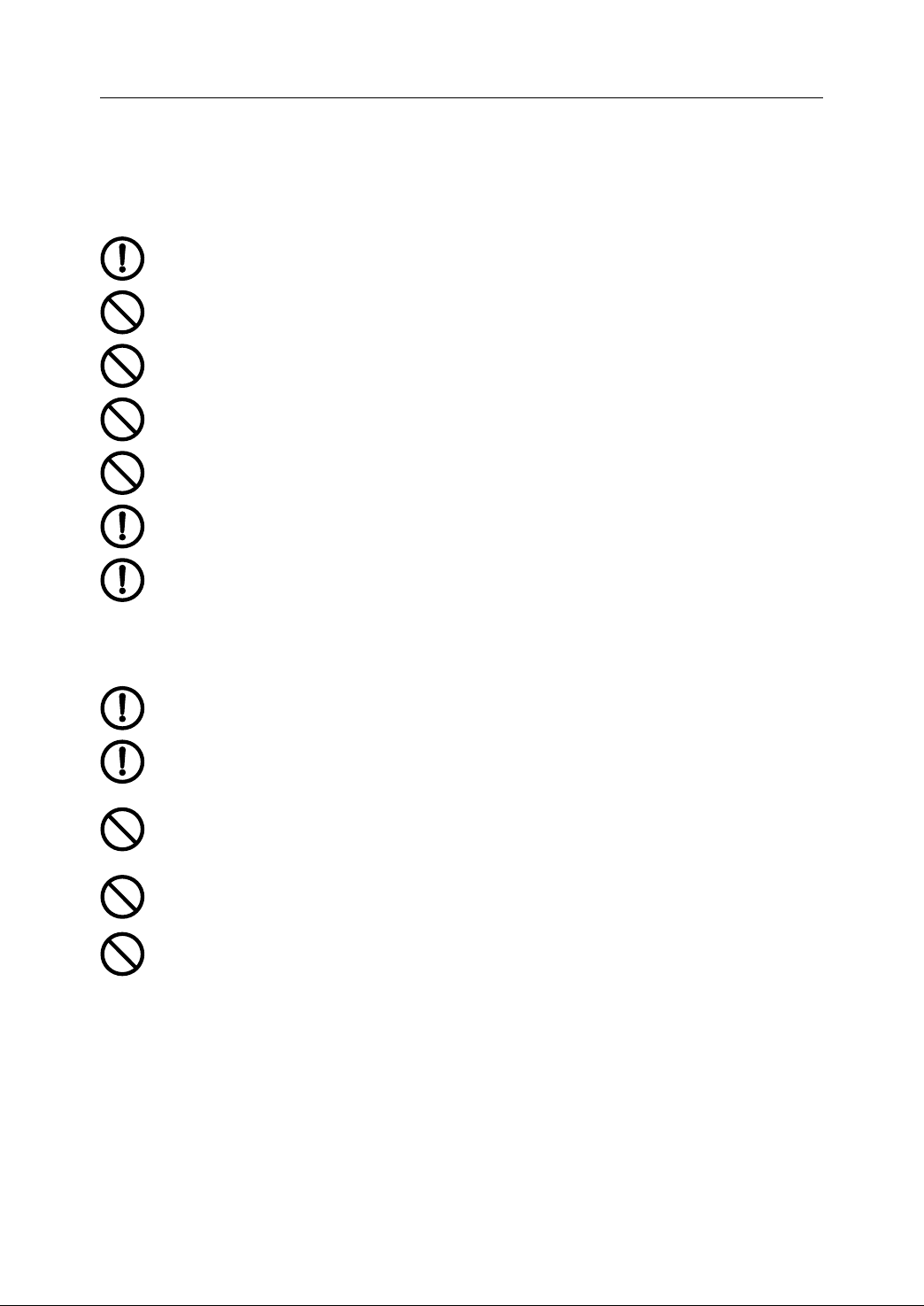
The product should be transported properly according to its weight.
The number of products stacked must not be more than what stipulated.
Do not climb up or stand on the product. Do not stack heavy things on it.
Dragging its cable to move or lift the product is not allowed.
Protect the front panel and screen from impact and cut.
Keep damp-proof while storing and transporting.
Let us know in time if the product has been stored overtime.
Installation
Installation
Installation
Because its casing is not of waterproof design, the product sh all be installed in
a cabinet to prevent from being rained on or directly sun-scorching.
and
Storage
and
Storage
and Storage
Storage
There sh all be enough space as required between the product and the cabinet
case or other devices.
The product sh all work in the environment with good ventilation, without
inflammable air, and without the erosion by corrosive material such as abrasive,
oil-mist, metal powder etc. Any conductor as metal or machine oil is prohibited
to get into the product.
Do not put the product near any inflammable or explosive matter.
The installation sh all be firm and without v ibration. Do not throw or strike the
product while installing. Neither a ny colliding against n or loading on the product
is allowed.
2
Page 13
1. Precaution
1.1.3
1.1.3
1.1.3
1.1.3 Wiring
Wiring
Wiring
Wiring
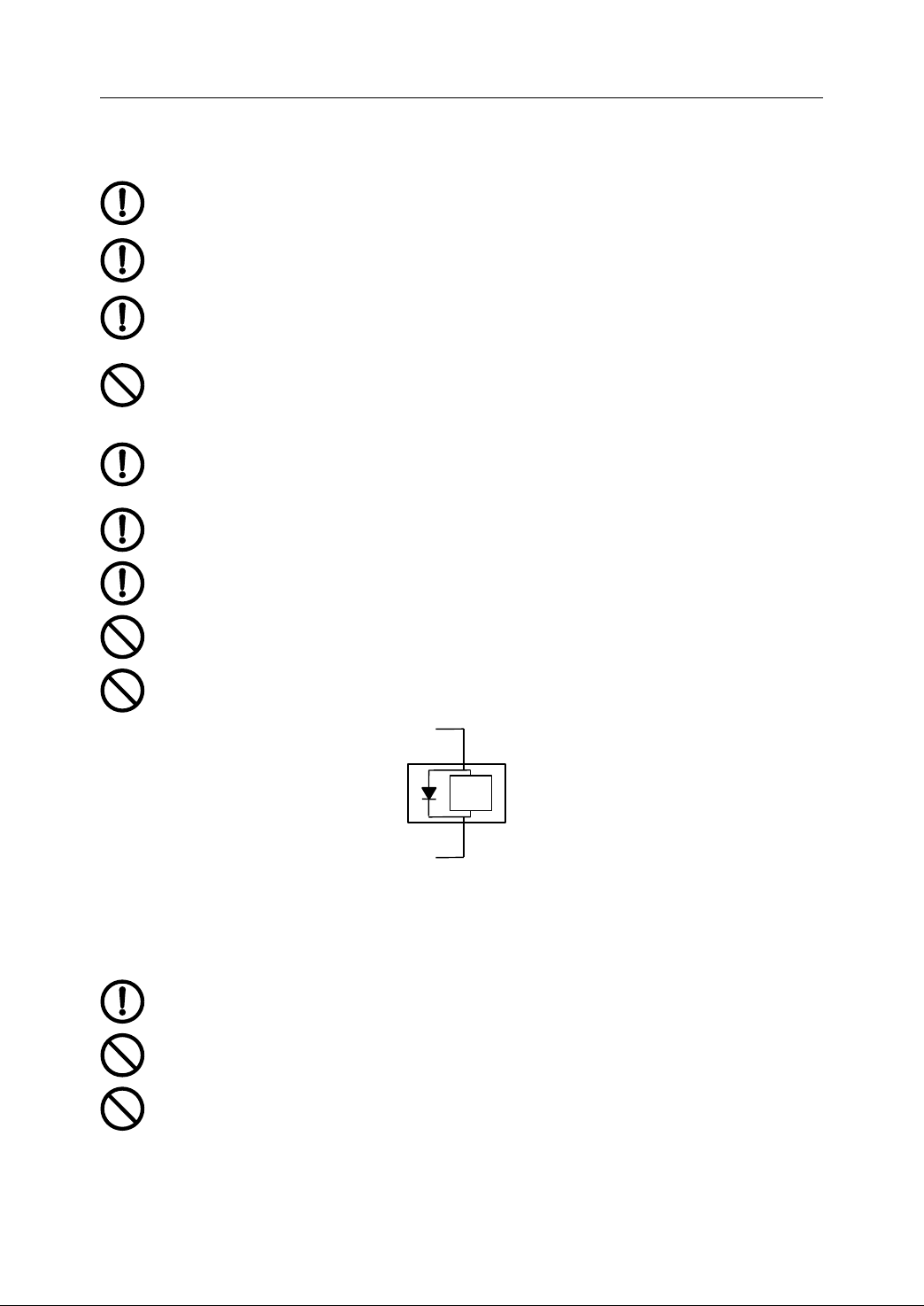
Workers undertaking wiring or inspection must be qualified to do the jobs.
The NC device must be grounded reliably . T he earth-resistance must be less
than 4 ohm. Do not take the neutral as a ground . O therwise , the system may
not work normally and stably because of interference.
Wiring s hall be correct and firm to avoid wrong operation.
Do not transfer either the position signal from NC device to servo driver unit or
the position feedback signal from position frequency converter to servo driver
unit and NC device through terminals or sockets . O therwise , the NC device may
not work owing to interference.
Any voltage at terminals must have its correct value and polarities (+, -) as
mentioned in the manual . O therwise , the short circuit or permanent damage to
the machine may occur.
The surge-absorbed diode of DC relay controlled by PLC output signal from NC
device must be wired as shown in F igure 1-1 to prevent the damag e t o device.
A
perso n n el’s hands must be kept dry while touching the plugs or switches to
avoid getting an electric shock or resulting in device damage.
Any tear on electric wires is not allowed. The wires sh all not be squeezed to
avoid leakage or even short-circuit.
It is absolutely not allowed to insert or pull out any plug or open the NC cabinet
door with the power supply on.
1.1.4
1.1.4
1.1.4
1.1.4 Commissioning
1.1.5
1.1.5
1.1.5
1.1.5 Operation
Commissioning
Commissioning
Commissioning
Before putting the device in motion, check the parameter setting at first.
Incorrect settings would lead to unexpected results.
Set parameter in its permissible range. Oversetting may lead to unstable
operation or even the damag e to the device.
Check if the cables of servomotor and the encoder wires are corresponding to
each other.
Operation
Operation
Operation
PLC output
Relay coil
DC+24V
Figure 1 1 the surge-absorbed diode
3
Page 14
1. Precaution
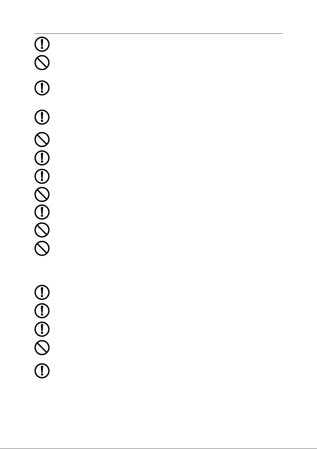
Personnel to operate the device must be competent for their work.
Before plugging in to get the main source, make sure that the main switch is off
to avoid accidental start -up .
While doing electrical design, it sh all take into account that the emergency stop
button of NC device could cut the power supplies for servo motion, spindle
motion and motions of all other moving parts when the system accidents occur.
For example, cut off the power supply (section 2. 9 for details ).
While designing or modifying the PLC programs, make sure that the operation
signal has been off before the reset alarm signal . For example, the spindle
rotation signal must be off before resetting the spindle alarm signal .
Do not refit the device.
To
prevent from or reduce the influence of electromagnetic interference on NC
device, refer to section 2.10 E lectromagnetic Compatibility Design.
To
reduce the electromagnetic interference, a low-pass filter can be added i f
there are electronic devices .
Do not turn on and off the system frequently . T he interval between on and off
operations must be at least 3 minutes.
T he operator’s hands must be kept dry, clean and no greasy dirt during
operation . It is suggested to keep the clear protection film on the panel.
Do not press the keys hard . It is not allowed to strike at the keyboard with
wrench or other sharp-edged and hard articles.
Operators shall not leave the machine while operating the devices.
1.1.6
1.1.6
1.1.6
1.1.6 Maintenance
Maintenance
Maintenance
Maintenance
Power supply sh all be turned off before checking, replacing or installing parts or
elements.
When short-circuit or overload happens, do not turn on the power again un less
checking and fixing the breakdown.
When alarm has happened, do not restart the device un less the accident is
cleared off.
Do not install or operate the device if it is damaged or lack of p arts and
elements.
The aging of electrolytic capacitors may lead to low performance.
damages arising from there, the electrolytic capacitors should be replaced,
under the normal operation conditions, every ten years. Please c ontact with us
at any time to solve the relevant problems.
To
avoid the
4
Page 15

1. Precaution
1.1.7
1.1.7
1.1.7
1.1.7 Waste
1.1.8
1.1.8
1.1.8
1.1.8 General
Waste
Waste
Waste Treatment
Treat the wastes as ordinary industrial wastes.
General
General
General Instructions
While putting the device in operation, install the cover plate and safety
equipment perfectly and operate the device as mentioned in manuals.
Read over chapter 2.10 Electrical Design in detail and notice all the
emphasized points.
Treatment
Treatment
Treatment
Instructions
Instructions
Instructions
5
Page 16
1. Precaution
1.2
Unpacking
1.2
Unpacking
1.2
1.2 Unpacking
Unpacking and
and
and
and Checking
Checking
Checking
Checking
1.2.1
1.2.1
1.2.1
1.2.1 List
After unpacking, please make sure that :
- The product is what you ordered.
- No damage occurs during transportation.
- The received components included the accessories are complete and without
Please Contact us in time if any problem exists .
1.2.2
1.2.2
1.2.2
1.2.2 Product
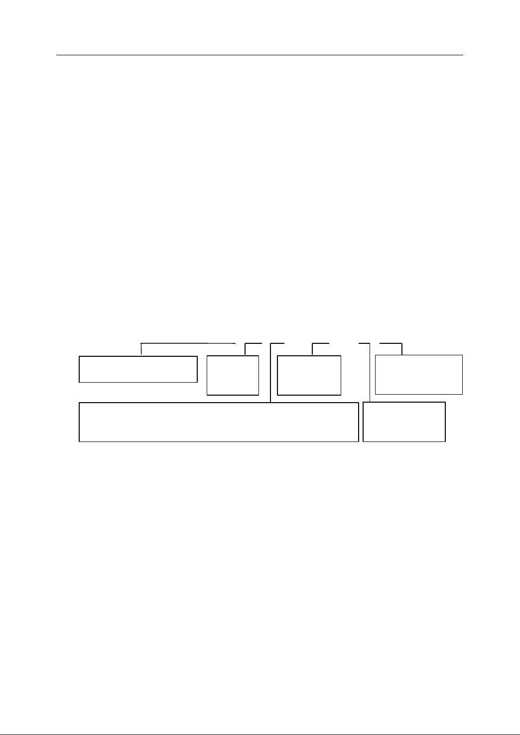
The following is the description of HNC- 21 .
List
List
List
damage.
Product
Product
Product Type
21: NC of standard type
22: NC of advanced type
Type
Type
Type
HNC
HNC
HNC
HNC –
–
–
– 21
21
21
21 M
Unit Type
M: Milling
T:
Turning
M
D
–
M
D
M D
D –
32
–
32
– 32
32 –
Storage Size
MB
–
H
–
– H
02
H
02
H 02
02
Memory Size
Flash RAM – MB
Hard disk -- GB
T
ype of feed axis
D: pulse interface for pulse servo or step per motor driver
Figure 1 2 Description of HNC-21
6
Memory type:
F: Flash RAM
H: IDE hard disk
Page 17
1.3
Esc
Tab
GECYBZ
QRFH
S T
%
SP
\:;
[8]^
6 7
2 3 4
BS
Enter
Upper
-
=+/
0
.
Del
Alt
Pgdn
+X
+Z
快进
-X
+4TH -Y
-4TH+Y-Z
循环
启动
进给
保持
V
J K
W L
P N
O
X
A
D
M
"
5
#
1
*
9
Pgup
+-
100%
100%
- +
快速修调主轴
制动
刀具
松/紧主轴修调
+-
100%
进给修调主轴
反转
主轴
定向
回 零
1000
冷却
开停
主轴正转机床锁住主轴
停止
主轴
冲动
换刀
允许
I
U
主轴
停止
主轴
冲动
换刀
允许
主轴
正转
主轴
定向
冷却
开停
F5F4 F6
主轴
反转
主轴
制动
进给
修调
-
快速
修调
- +
+
100%
100%
-Z
-X
刀具
松/紧主轴修调
-
F8F7 F9
+
100%
+4TH
F10
+X
-4TH+Y
快进
+Z-Y
PgDn
EnterAlt
SP
[8]^
6 75
#
+
PgUp
*9/
.
0
Upper
Shift
Del
=
-
BS
R
W
:1"
2 3
;
I
U
M
D
V
J K
H
S T
4
\
%
P
L
F
Q
O
N
Tab
CXA B
Y Z G
E
Esc
a ) HNC - 21
b ) HNC - 2 2
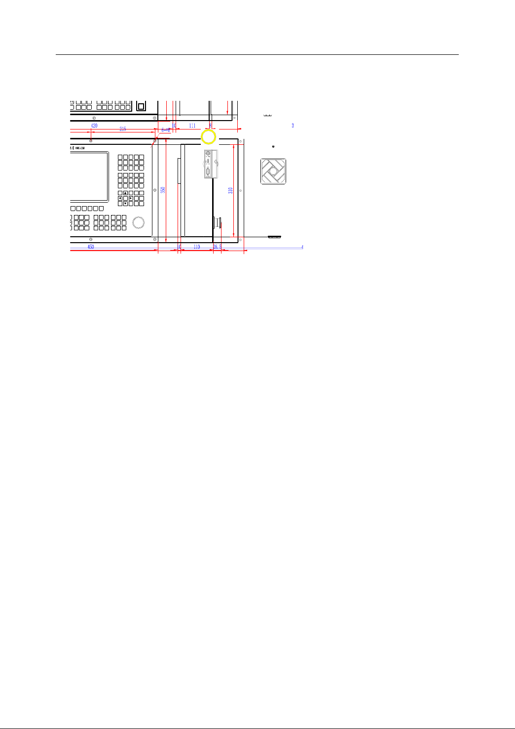
Dimensions
1.3
Dimensions
1.3
1.3 Dimensions
Dimensions
1. Precaution
Figure 1 3 Dimension of HNC-21/22
7
Page 18
1. Precaution
Esc
Tab
GECYBZ
Q
RFH
S T
%
SP
\:;
[8]^
6 7
2 3 4
BS
Enter
Upper
-
=+/
0
.
Del
Alt
Pgdn
+X
+Z
快进
-X
+4TH -Y
-4TH+Y-Z
循环
启动
进给
保持
V
J K
W L
P N
O
X
A
D
M
"
5
#
1
*
9
Pgup
+-
100%
100%
- +
+-
100%
I
U
100
1 5
1 5
1.4
Installation
1.4
Installation
1.4
1.4 Installation
Installation
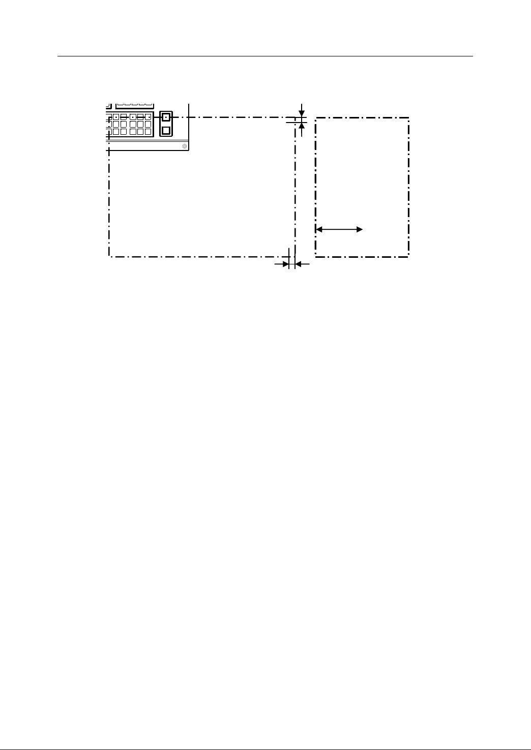
Figure 1 4 Dimension of Installation (HNC-21 as an example)
Please note the following items when designing the cabinet (control cabinet, console,
and pendant box) .
1. As shown in Fig ure 1-4 , it needs to have at least a 100mm-space between NC
device and the rare wall of the cabinet to facilitate plugging the cables and heat
radiation .
2. The cabinet structure must be of IP54 protection class. S ome requirements
should be met :
1) The material used to make the cabinet must bear any mechanical, chemical,
or heat stress and the moisture influence normally happened .
2) It needs to stick the adhesive tape along the door crack to eliminate the
gap .
3) The cable entrances must be sealed properly, so that it can be unsealed
easily if necessary .
4) Fans or heat exchanger must be equipped to radiate the heat from cabinet .
5) If fans are used, the air filters are required at both inlets and outlets .
6) Be careful not to let the dust come into the cabinet through heat dissipation
holes. Dust or other materials such as cutting lubricant, mist can get into the
device and attach itself to circuit board to make the insulation aging and
even lead to circuit damage. Therefore, it needs to know the environment
and the direction of air discharge; the warm air stream should be directed
8
Page 19

1. Precaution
Air flow
NC cabinet
Machine tool
against the pollution source, as shown in Fig ure 1-5.
Figure 1 5 Air flow direction in NC cabinet
3. Temperature in the cabinet shall not be higher than 50 ℃ . Alternatively, more
effective steps shall be applied to dissipate the heat.
4. The control panel must be placed where the coolant or other liquid does not
reach .
5.
To
reduce electromagnetic interference, k eep cables or electric components
having supply voltage higher than 50V apart from NC device at least 100mm .
6. The NC device should be installed where the commissioning and maintenance
can be done conveniently .
9
Page 20

1. Precaution
1.5
Environmental
1.5
Environmental
1.5
1.5 Environmental
Environmental Requirement
Requirement
Requirement
Requirement
1.5.1
1.5.1
1.5.1
1.5.1 Weather
The NC device works normally in the environment shown as follows.
- A mbient temperature : 0 ~ 40 ℃
- R elative humidity : 30% ~ 95% ( without dew )
- A tmospheric pressure : 86 ~ 106k Pa
1.5.2
1.5.2
1.5.2
1.5.2 Elevation
The NC device works normally with an elevation of less than 1000 m.
1.5.3
1.5.3
1.5.3
1.5.3 Transportation
It is proper to transport and store the NC device within a temperature range of
(-40 ℃ ~ +55 ℃ ). The device can survive up to 70 ℃ in a short-term, less than 24
hours, transportation or storage. It is necessary to adopt moisture-proof, shockproof
and impact-resistant measures to avoid damage .
Weather
Weather
Weather Condition
Elevation
Elevation
Elevation
Transportation
Transportation
Transportation and
Condition
Condition
Condition
and
Storage
and
Storage
and Storage
Storage
1.5.4
1.5.4
1.5.4
1.5.4 Mechanical
The NC device sh all be installed far from any shock resource to prevent from the
influence of shock, impulse and impact. If the device has to be installed near these
resources, additional measures are necessary to ensure the NC device against
resonance, and the vibration amplitude must be less than 0.05mm (frequency range:
5-55 Hz) .
1.5.5
1.5.5
1.5.5
1.5.5 Environmental
While transporting, storing or operating, keep the NC device out of the strong
microwave radiation and the strong electromagnetic interference. Do not let
excessive pollutants (dust, acid, corrosive gas, salty matter) intrude into NC device.
The device should not work in an environment accompanied with strong vibratio n.
10
Mechanical
Mechanical
Mechanical Environment
Environmental
Environmental
Environmental Pollution
Environment
Environment
Environment
Pollution
Pollution
Pollution
Page 21

HNC- 21/22 Connection Manual
2
Connection
2
Connection
2
2 Connection
Connection
Thi s chapter would introduce:
-
Total
connection diagram
- I nterface
- Power supply connection
- Connection to DNC
- Connection to computer
- I/O on NC device
- Connection to handwheel unit
- Connection to spindle device
- Connection to feed drive
- Design of E-Stop and Overtravel Released
- Design of Electromagnetic Compatibility
11
Page 22

2. Connection
Power s
upply
Keyboard
XS1
XS
30 -
XS3
5
XS2
XS
8
XS3
XS
9
XS5
XS
10 - XS12
XS
7
XS20 - XS22
On-off input
Feed device
On-off output
USB
Ethernet
RS232
Handheld unit
Spindle unit
2.1
Total
2.1
Total
2.1
2.1 Total
Total Connection
This section shows the total connection diagram of HNC-21/22.
Connection
Connection
Connection Diagram
Diagram
Diagram
Diagram
[Note]
[Note]
[Note]
[Note]
(1) As it is shown Fig ure 2 - 1, HNC- 21/22 controls various types of feed units
(2) PLC I/O (maximum: 60/48) can be connected through XS10-XS12 (input),
(3) The interface to connect to the third axis on HNC-21 or the fourth axis on
(4) The interfaces XS12 and XS22 which provide 20/16 I/O are optional.
(5) Ethernet interface XS3 is optional.
Figure 2 1
through XS 30 -XS3 5. Up to six different types of feed device can be connected.
XS20-XS22 (output).
HNC-22 is optional.
Total
Connection Diagram of HNC-21/22
12
Page 23
2.2
Interface
2.2
Interface
2.2
2.2 Interface
Interface
2. Connection
2.2.1
2.2.1
2.2.1
2.2.1 NC
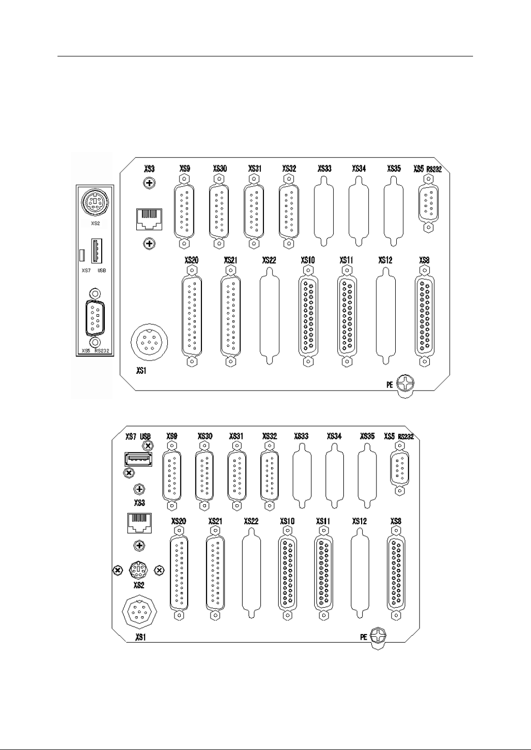
Th is section shows the interface of HNC-21.
NC
Device
NC
Device
NC Device
Device
Figure 2 2 Interface of HNC-21
Figure 2 3 Interface of HNC-22
13
Page 24
2. Connection
RS232 switcher
PC keyboard switcher
Ethernet switcher
RS232 Interface
PC keyboard interface
Ethernet Interface
Ethernet switcher
RS232 switch er
PC keyboard switcher
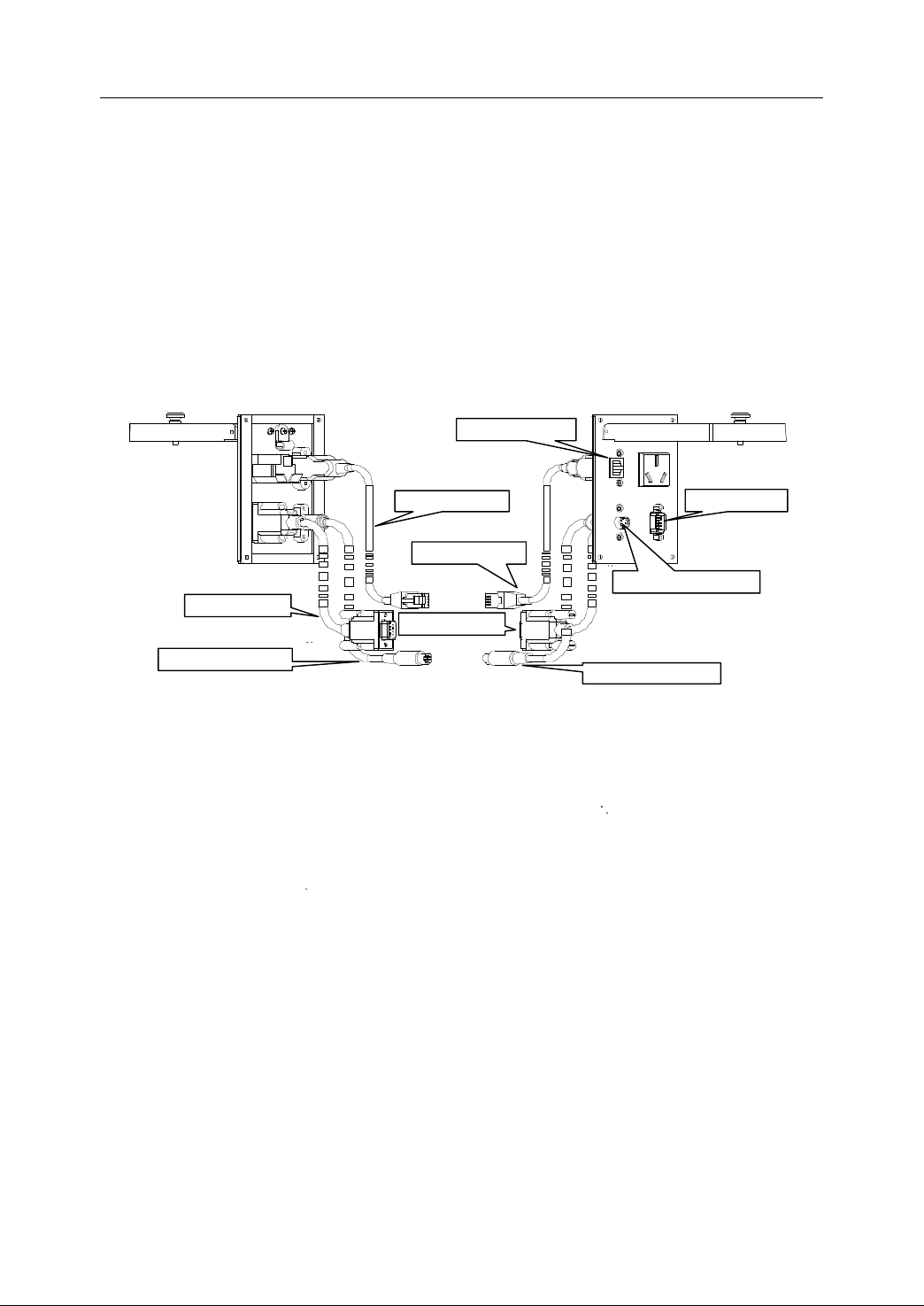
XS1: Power supply interface XS2: Keyboard interface
XS3: Ethernet interface XS5: RS232 interface
XS7: USB interface XS8: Handwheel unit interface
XS9: Spindle control interface X10~X12: PLC inputs interface
X20~X22: PLC outputs interface X30~X35: feed axis control interface
2.2.2
2.2.2
2.2.2
2.2.2 DNC
There are RS232, PC keyboard and E thernet interfaces on DNC unit . The following
Fig ure 2-4 shows the interface of DNC unit .
As it is shown in Figure 2-4, the interfaces are used to connect with PC or other
devices, and the switchers are used to connect with HNC-21/22. The interfaces on
DNC unit correspond with the interfaces shown in Figure 2-2 or Figure 2-3.
DNC
DNC
DNC unit
unit
unit
unit (optional)
(optional)
(optional)
(optional)
Figure 2 4 Interface of DNC unit
2.2.3
2.2.3
2.2.3
2.2.3 Handwheel
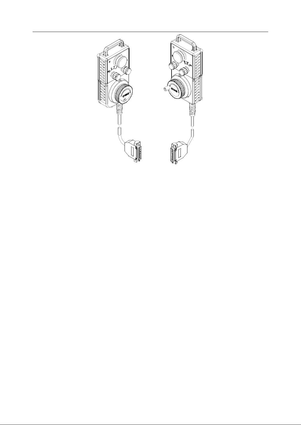
As it is shown in Figure 2-5, t he handwheel unit is equipped with the emergency stop
button, pilot lamps, axis switch (OFF, X,
and the manual pulse generator. It is connected to XS8 of HNC-21/22.
14
Handwheel
Handwheel
Handwheel unit
unit
unit
unit (optional)
(optional)
(optional)
(optional)
Y,
Z), m agnification switch (X1, X10, X100) ,
Page 25
DB25 PIN
Figure 2 5 Interface of Handwheel unit
2. Connection
2.2.4
2.2.4
2.2.4
2.2.4 I/O
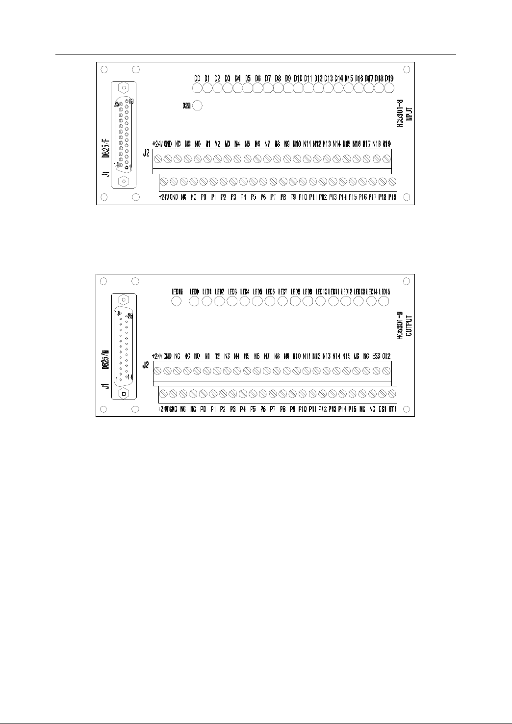
There are two kinds of I/O terminal boards – input terminal boards and output
terminal boards. They are usually used as a switcher unit to connect XS 10, XS11,
XS12, XS20, XS21, and XS22 of HNC-21 /22 .
Each input terminal board or output terminal board contains both NPN and PNP
terminals.
E ach input terminal board contains 20 bit input terminals . Each output terminal
board contains 16 bit output terminals, 2 bit emergency-stop terminal, and 2 bit
overtravel terminal.
- I nput terminal board
I/O
Terminal
I/O
Terminal
I/O Terminal
Terminal Boards
Boards
Boards
Boards (optional)
(optional)
(optional)
(optional)
15
Page 26
2. Connection
- O utput terminal board
Figure 2 6 Input terminal board
Figure 2 7 Output terminal board
16
Page 27
2.3
DC
24V ≥50W
+24V
24V GND
External supply
2
Casing ground
HNC-21
AC
24V ≥100W
XS1
1
5
2
AC 24V
AC 24V
External supply
1
4
6
Power
2.3
Power
2.3
2.3 Power
Power Supply
Supply
Supply
Supply Connection
Connection
Connection
Connection
2. Connection
2.3.1
2.3.1
2.3.1
2.3.1 General
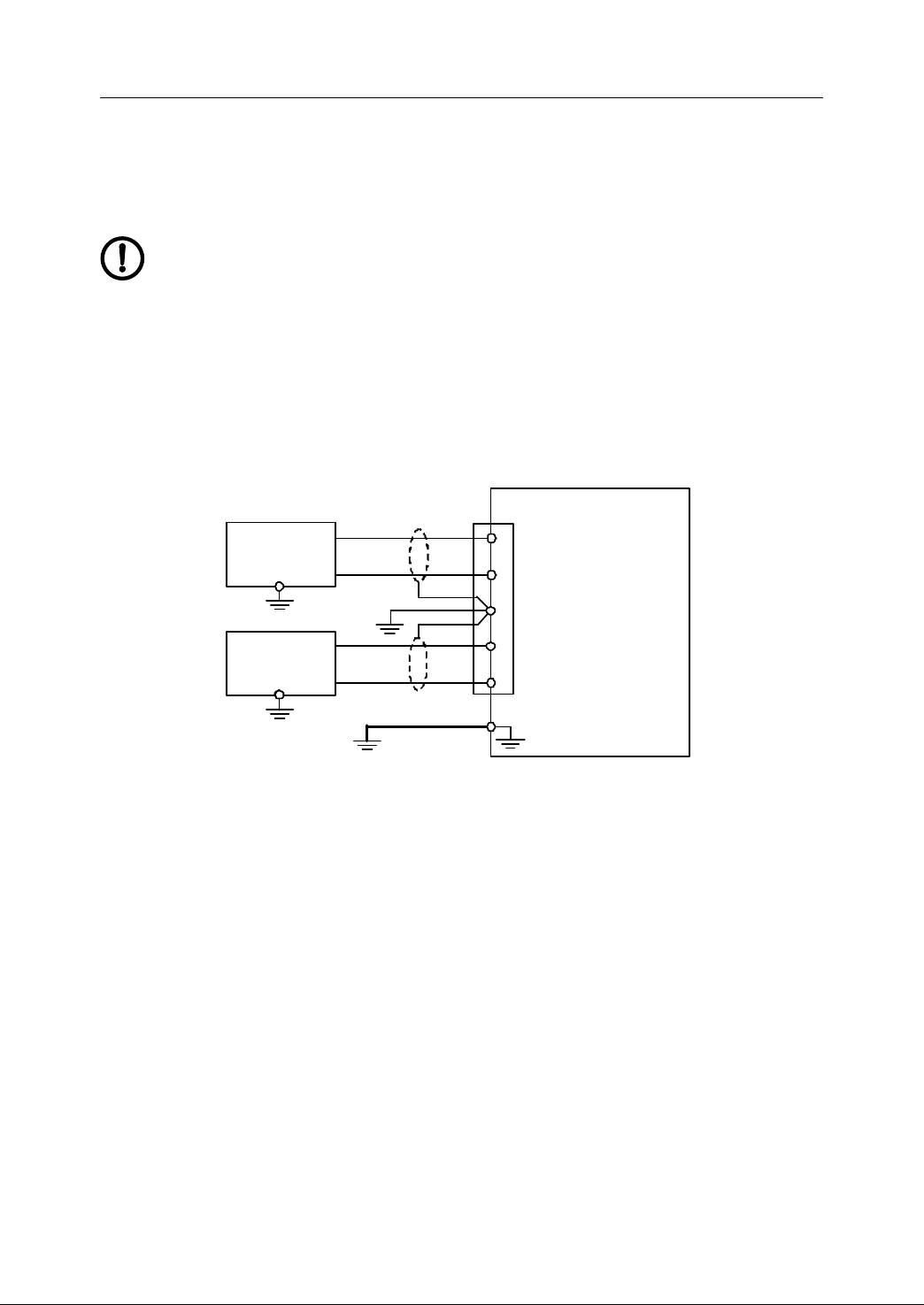
If the external supply 1 is of AC 24V, an independent power supply for NC device is
suggested to use (refer to Fig ure 2 -8 ) .
General
General
General Requirement
NC device (External supply 1) : AC24V , or DC24V/100W;
PLC power (External supply 2): DC24V, no less than 50W;
Cables: Shielded cables or twisted cables ;
Requirement
Requirement
Requirement
Figure 2 8 Power Supply 1
It is suggested to use a switch supply of DC 24V for the external supply 2. It is
proper to increase the supply capacity in case there are many DC 24V relays
controlled by PLC outputs, or to have an additional power supply, having a common
ground with the external supply 2. If the brake of Z axis (spindle) and
electromagnetic valves also require DC 24V supply , try to use another supply (not
the external supply 2) to prevent NC device from interference induced by loads with
large inductance .
I f the external supply 1 is of DC 24V , it is allowed to have a shared switching supply,
having capacity of no less than 1 45 W for both the external supply 1 and the external
supply 2 (refer to Fig ure 2 -9 ) .
17
Page 28
2. Connection
Casing ground
HNC - 21 /22
DC24V
≥ 1 5 0W
XS1
1, 2
4, 5
6
+24V
24V G ND
External supply
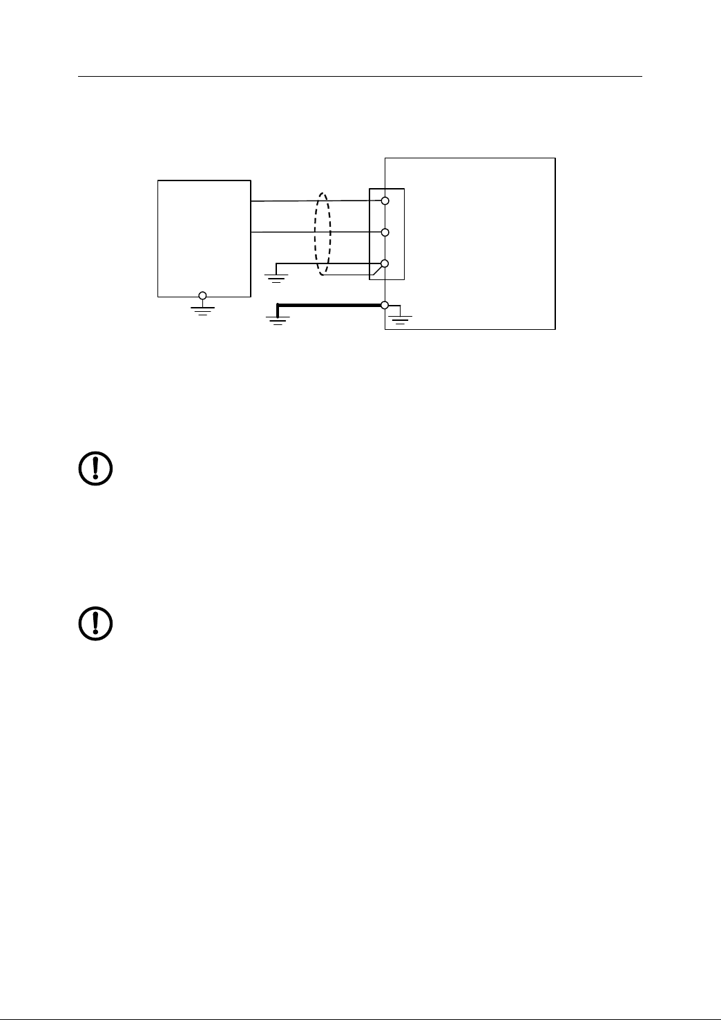
As shown in Fig ure 2 -10 , the external supplies 1 and 2 provide power for PLC
elements and manual pulse generator of handwheel unit through the interface XS8
on NC device .
Figure 2 9 Power Supply 2
2.3.2
2.3.2
2.3.2
2.3.2 Grounding
- Protective Grounding
Grounding
Grounding
Grounding
T he ground wire of power supply (pin 6 of XS1) is connected with PE
interface of NC device. An additional copper ground wire at le ast 2.5 mm
shall be taken as the ground wire and connected with PE interface of NC
unit , since the ground wire of the power cable is thin.
- Signal Grounding
The pin 4 of XS1 (DC 24VG) is connected to pin 1, 2, 14, and 15 of XS10,
XS11, XS12, XS20, XS21, and XS2 2 . Moreover, t o reduce the current
passing the pin 4 (DC 24V G ) of XS1 and to raise the anti-interference ability
of PLC signals , those pins (1, 2, 14, 15) sh all be connected to the ground of
external supply DC 24V (Figure 2-10).
2
18
Page 29

2. Connection
HNC -21/22
Int ern al
circuit
Handhe ld un it
+24V
+
24V
+24V
24V G ND
24V G
24V
24V G ND
24V G
XS10
, 11
,12
XS20 ,21
,22
XS8
Ext
ern al
supply 2
DC24V ≥
50W
XS1
2
4
6
+5V
5V G
3
,16
1,14
2,15
25
13
1,14
2,15
P ower s upply 2
DC 24V ≥ 1 50W
Figure 2 10 Signal grounding
In case some electrical components (such as relays, pilots in buttons,
approach switches, and Hall switches) to control or receive signals from
I/O have their independent power supply, the supply should have common
ground with the supply of these inputs and outputs, Otherwise , NC device
can not control those electrical components or receive signal from th o se
component s reliably .
19
Page 30
2. Connection
XS5
XS3
XS2
HNC - 21/22
DNC
DNC
DNC
DNC
unit
unit
unit
unit
XS5’
XS3’
XS2’
NC device
NC device
NC device
NC device
Keyboard switcher
Ethernet
switcher
RS232
switcher
1 DATA
3 GND
4 VCC
5 CLOCK
1 TX _ D1+
2 TX_D1 -
3 RX_D2+
4 BI_D3+
5 BI_D3 -
6 RX_D2 -
7 BI_D4+
8 BI_D4 -
2 RXD
3 TXD
5 G ND
HNC - 21 /22
DNC unit
XS2
XS3
XS5
DATA 1
GND 3
VCC 4
CLOCK 5
TX _ D1+ 1
TX_D1 - 2
RX_D2+ 3
BI_D3+ 4
BI_D3 - 5
RX_D2 - 6
BI_D4+ 7
BI_D4 - 8
RXD 2
TXD 3
GND 5
XS5 ’
C
able length
<1
m
2.4
Connection
2.4
Connection
2.4
2.4 Connection
Connection to
to
DNC
to
DNC
to DNC
DNC unit
unit
unit
unit
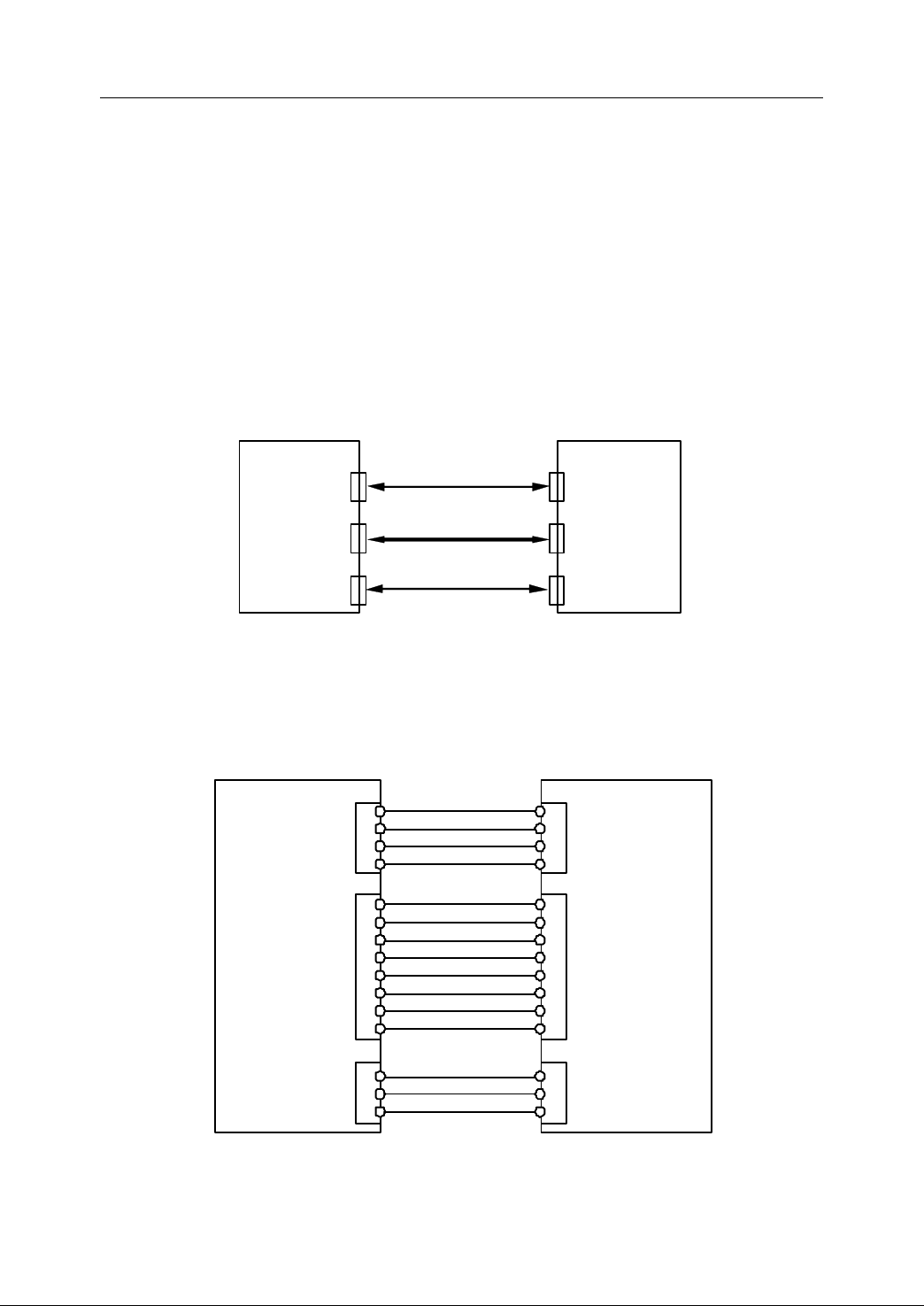
DNC unit is a unit for interface switcher, which are DNC (RS-232) interface, PC
keyboard (PS2) interface, Ethernet interface .
Since there are DNC (RS-232) interface, PC keyboard (PS2) interface, and USB
interface on HNC-21, DNC unit is mainly used on HNC-22.
The following figure is the connection between DNC unit and NC device.
Figure 2
11
Connection between DNC and NC unit
The distance between DNC unit and NC device should not be longer than one meter.
The following figure shows the detailed connection between DNC and NC unit.
Figure 2 12 Detailed connection between DNC and NC unit
20
Page 31
2. Connection
PC
NC device
2 RXD
3 TXD
5 GND
XS5
RXD 2
TXD 3
G ND 5
RS232
C able length <15m
PE
PC
DNC unit
NC device
2 RXD
3 TXD
XS5
RXD 2
TXD 3
XS5’
2 RXD
3 TXD
XS5
RXD 2
TXD 3
<15
m
C abin et
<1
m
PE
5 GND
GND 5
5 GND
GND 5
2.5
Connection
2.5
Connection
2.5
2.5 Connection
Connection to
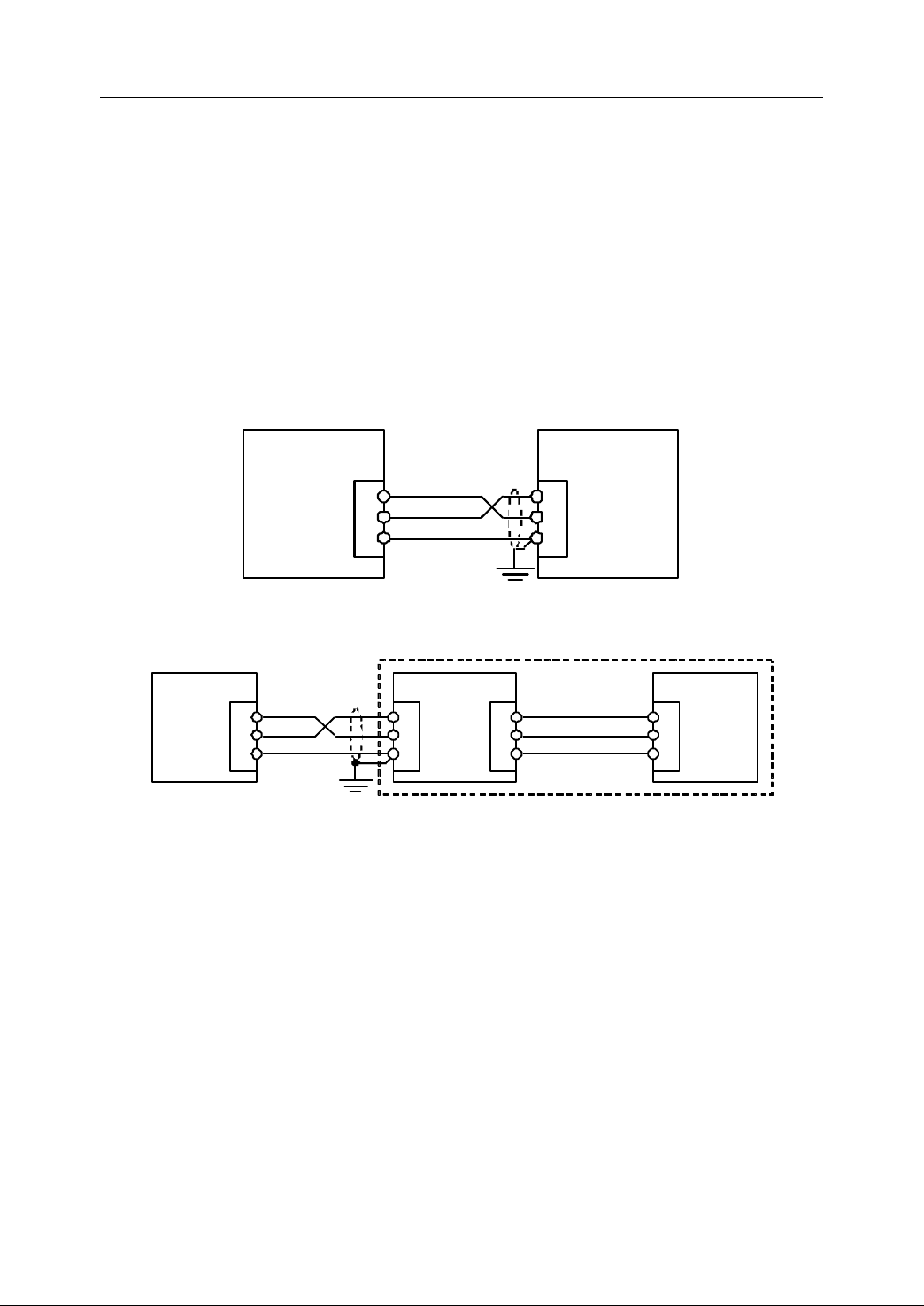
HNC-21/22 can be connected to PC by using RS232 or Ethernet interface, so that
the data can be shared and exchanged. The operator can directly use the interface
XS3 or XS5 on NC device, or use the optional DNC unit to connect NC device with
PC.
to
Computer
to
Computer
to Computer
Computer
2.5.1
2.5.1
2.5.1
2.5.1 RS232
RS232
RS232
RS232 Interface
Interface
Interface
Interface
Figure 2 13 Connect with PC by RS232 (no DNC unit)
Figure 2 14 Connect with PC by RS232 (with DNC unit)
2.5.2
2.5.2
2.5.2
2.5.2 Ethernet
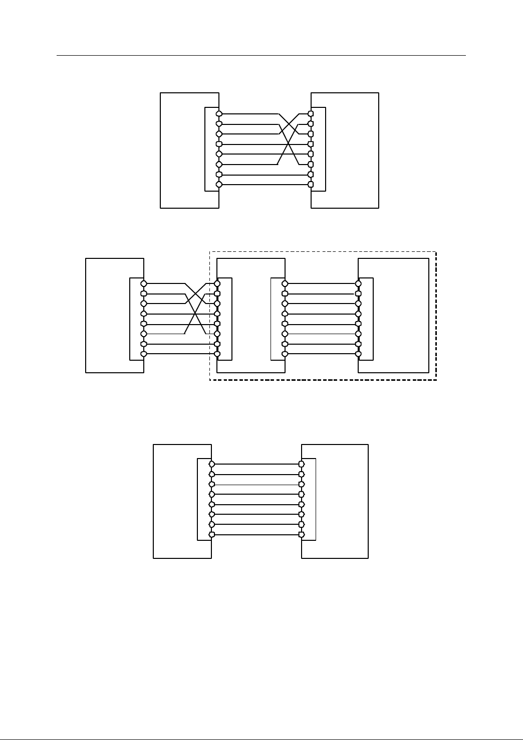
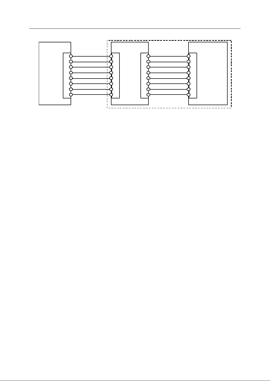
It is easy and reliable to connect NC device with the computer through E thernet
interface . The operator can use the cable to directly connect with PC ( Fig ure 2 -15,
Figure 2-16 ) , or use an HUB t o connect with any computer in local area network
(Fig ure 2 -17, Figure 2-18 ). The connection can be made either through Ethernet
interface at the rare of NC device, or through the interface of DNC unit .
Note:
Note:
Note:
Note:
1. The special network cables sh all be used while wiring.
2. The type of Ethernet interface is RJ45 .
Ethernet
Ethernet
Ethernet Interface
Interface
Interface
Interface
21
Page 32
2. Connection
PC
HNC-21
NC device
HNC
- 21/22
1 TX _ D1+
2 TX_D1 -
3 RX_D2+
4 BI_D3+
5 BI_D3 -
6 RX_D2 -
7 BI_D4+
8 BI_D4 -
XS3
TX _ D1+ 1
TX_D1 - 2
RX_D2+ 3
BI_D3+ 4
BI_D3 - 5
RX_D2 - 6
BI_D4+ 7
BI_D4 - 8
Ethernet
<50
m
PC
HNC - 21 /22
DNC unit
NC device
C abin et
1
2
3
4
5
6
7
8
XS3
TX_D1+ 1
TX_ D1- 2
RX_D2+
3
BI_D3+
4
BI_ D3- 5
RX_ D2- 6
BI_D4+
7
BI_ D4- 8
Ether net
<50m
1 TX _ D1+
2 TX_D1 -
3 RX_D2+
4 BI _D3+
5 BI_D3 -
6 RX_D2 -
7 BI_D4+
8 BI_D4 -
TX _ D1+ 1
TX_D1 - 2
RX_D2+ 3
BI_D3+ 4
BI_D3 - 5
RX_D2 - 6
BI_D4+ 7
BI_D4 - 8
XS3 ’
<1
m
HUB
HNC - 21
NC device
HNC -21/22
1 TX _ D1+
2 TX_D1 -
3 RX_D2+
4 BI_D3+
5 BI_D3 -
6 RX_D2 -
7 BI_D4+
8 B I_D4 -
XS3
TX _ D1+ 1
TX_D1 - 2
RX_D2+ 3
BI_D3+ 4
BI_D3 - 5
RX_D2 - 6
BI_D4+ 7
BI_D4 - 8
interface
<50
m
- U sing cables
Figure 2 15 Use cables to connect with PC by Ethernet interface (no DNC unit)
Figure 2 16 Use cables to connect with PC by Ethernet interface (with DNC unit)
- U sing HUB
Figure 2 17 Use HUB to connect with PC (no DNC unit)
22
Page 33
2. Connection
HUB
HNC - 21 /22
DNC unit
NC device
Cabinet
1
2
3
4
5
6
7
8
XS3
TX _ D1+ 1
TX_D1 - 2
RX_D2+ 3
BI_D3+ 4
BI_D3 - 5
RX_D2 - 6
BI_D4+ 7
BI_D4 - 8
<50
m
1 TX _ D1+
2 TX_D1 -
3 RX_D2+
4 BI_D3+
5 BI_D3 -
6 RX_D2 -
7 BI_D4+
8 BI_D4 -
TX _ D1+ 1
TX_D1 - 2
RX_D2+ 3
BI_D3+ 4
BI_D3 - 5
RX_D2 - 6
BI_D4+ 7
BI_D4 - 8
XS3 ’
<1
m
Figure 2 18 Use HUB to connect with PC (with DNC unit)
23
Page 34
2. Connection
IF=5~9mA
24V G ND
+5V
NPN i nput : 24V G ND
24V G ND
+ 2 4V
IF=5~9mA
+ 24V
+5V
PNP i nput : 24V
24V G ND
2.6
PLC
2.6
PLC
2.6
2.6 PLC
PLC I/O
Built-in I/O (40/32 bit, extended to 60/48 bit) on HNC-21/22 unit are connected to I/O
terminal board or output relay.
I/O
Interface
I/O
Interface
I/O Interface
Interface
2.6.1
2.6.1
2.6.1
2.6.1 Input
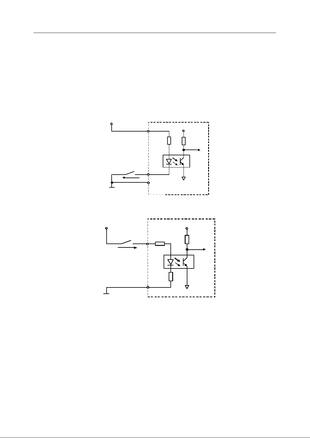
(1) E quivalent circuit
Input
Input
Input interface
interface
interface
interface
Figure 2 19 Equivalent circuit of NPN input interface
(2) T echnical parameters
24
Figure 2 20 Equivalent circuit of PNP input interface
Note
:
Note
:
Note
Note :
:
- The type of the input interfaces on HNC-21/22 unit is NPN.
- The input terminal board includes two types of input terminal: NPN and
PNP.
- The optically coupled technique is adopted. The highest isolated voltage is
Page 35
2. Connection
IF=5
~ 9mA
+ 2 4V
NPN input : 24V GND
a ) NP N input
N
24V G ND
IF=5~9mA
+ 24V
PNP input : 24V
b ) PNP input
P
24V GND
2500V RMS (one minute).
- The supply voltage is 24V.
- Turn-on current IF=5~9mA.
- The leak current≤0.1mA
- Filtering time is approximately 2msec.
Note:
Note:
Note:
Note: The power supply of a ny active switch units (such as non-contact switch,
Hall switch etc.) must be DC24V .
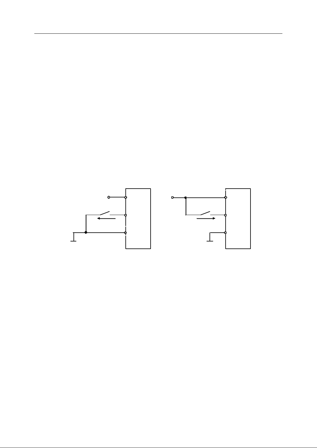
(3) Typical application of circuit
- Connection to external passive switches or relay contacts;
As it is shown in Figure 2-21, NPN or PNP input terminal can be used. One
contact is connected to the input interface, and the other contact is
connected to 24V (NPN input), or 24VG (PNP input).
Figure 2 21 Connection to passive switch or relay contacts
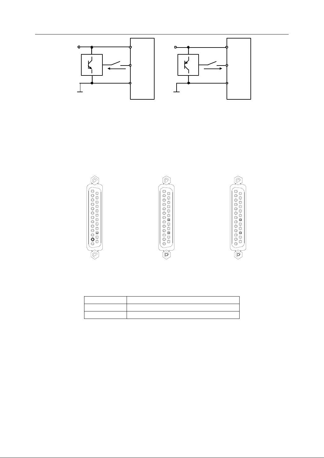
- Connection to external active switches
Selecting NPN or PNP input depends on the output type of module. Please
refer to the description of components, if necessary.
a) NPN input terminal shall be selected for NPN output type of the module
(Figure 2-22 a).
b) PNP input terminal shall be selected for PNP output type of the module
(Figure 2-22 b).
25
Page 36
2. Connection
I F=5~
9mA
+
24V
a ) NP N input
N
24V GND
+
24V
b ) PNP input
P
IF=5
~
9mA
24V
GND
14:24VG
15:24VG
16:X2.3
17:X2.1
18:X1.7
19:X1.5
20:X1.3
21:X1.1
22:X0.7
23:X0.5
24:X0.3
25:X0.1
1
13
14
25
1 :
24VG
2 :
24VG
3 :NC
4 :
X2.2
5 :
X2.0
6 :
X1.6
7 :
X1.4
8 :
X1.2
9 :
X1.0
10 :
X0.6
11 :
X0.4
12 :
X0.2
13 :
X0.0
XS10
(
DB25 PIN
)
14
:
24VG
15
:
24VG
16
:
X4.7
17
:
X4.5
18
:
X4.3
19
:
X4.1
20
:
X3.7
21
:
X3.5
22
:
X3.3
23
:
X3.1
24
:
X2.7
25
:
X2.5
1
13
14
25
1 :
24VG
2 :
24VG
3 :NC
4 :
X4.6
5 :
X4.4
6 :
X4.2
7 :
X4.0
8 :
X3.6
9 :
X3.4
1 0 :
X3.2
11 :
X3.0
12 :
X2.6
13 :
X2.4
XS11
(
DB25 PIN
)
14
:
24VG
15
:
24VG
16
:
X7.3
17
:
X7.1
18
:
X6.7
19
:
X6.5
20
:
X6.3
21
:
X6.1
22
:
X5.7
23
:
X5.5
24
:
X5.3
25
:
X5.1
1
13
14
25
1 :
24V
G
2 :
24VG
3 :NC
4 :
X7.2
5 :
X7.0
6 :
X6.6
7 :
X6.4
8 :
X6.2
9 :
X6.0
1 0 :
X5.6
11 :
X5.4
12 :
X5.2
13 :
X5.0
XS12
(
DB25 PIN
)
Figure 2 22 Connection of active input switch
(4) Pin of PLC input interface
� Input interface on NC device
Figure 2 23 Interface of XS10, X11 and XS12
Table 2 1 Description of XS10, XS11 and XS12
Signal Description
24VG External switch power DC24V Ground
X0.0~X7.3 PLC input (60 bit)
� Interface of input terminal board
26
Page 37
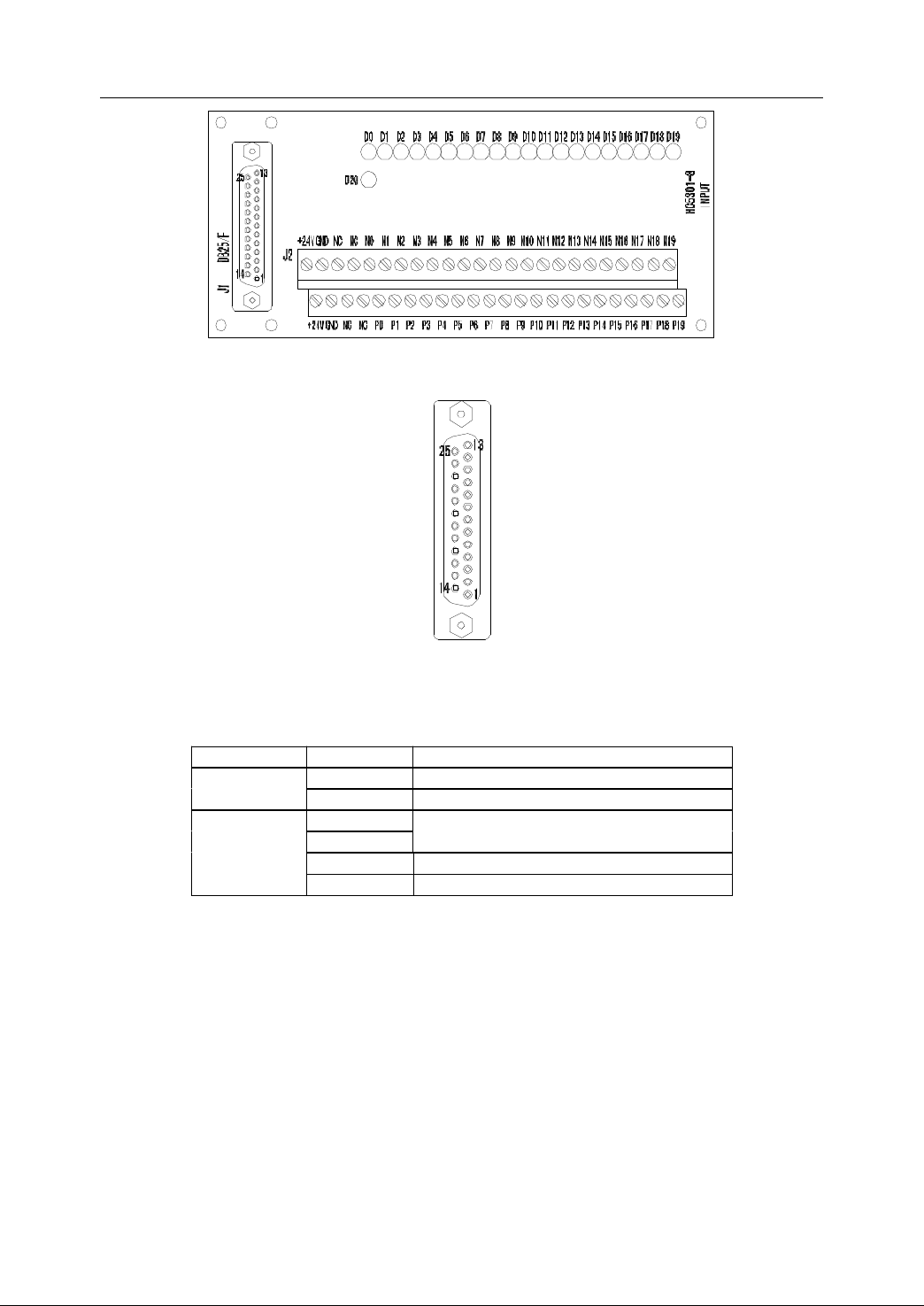
Figure 2 24 Input terminal board
25
:
NI1
24
:
NI3
23
:
NI5
22
:
NI7
21
:
NI9
20
:
NI11
19
:
NI13
18
:
NI15
17
:
NI17
16
:
NI19
15
:
24VG
14
:
24VG
13
:
NI0
12:NI2
11
:
NI4
10
:
NI6
9
:
NI8
8
:
NI10
7 :NI12
6
:
NI14
5
:
NI16
4
:
NI18
3
:
NC
2
:
24VG
1
:
24VG J1(
DB25/F
PIN
)
2. Connection
Figure 2 25 Interface of J1 on input terminal board
Table 2 2 Description of input J1 and J2
Interface Signal Description
J1 (DB25/F)
J2
24VG External switch power DC24V Ground
NI0~NI19 PLC input
+24V
GND
External switch power DC24V
N0~N19 NPN input terminal
P0~P19 PNP input terminal
Note:
Note:
Note:
Note: NPN and PNP can be used on the same bit.
2.6.2
2.6.2
2.6.2
2.6.2 Output
Output
Output
Output interface
interface
interface
interface
27
Page 38
2. Connection
IL≤ 100mA
+24V
+5V
24V G
round
L
IL≤ 100mA
+24V
+5V
24V
Ground
L
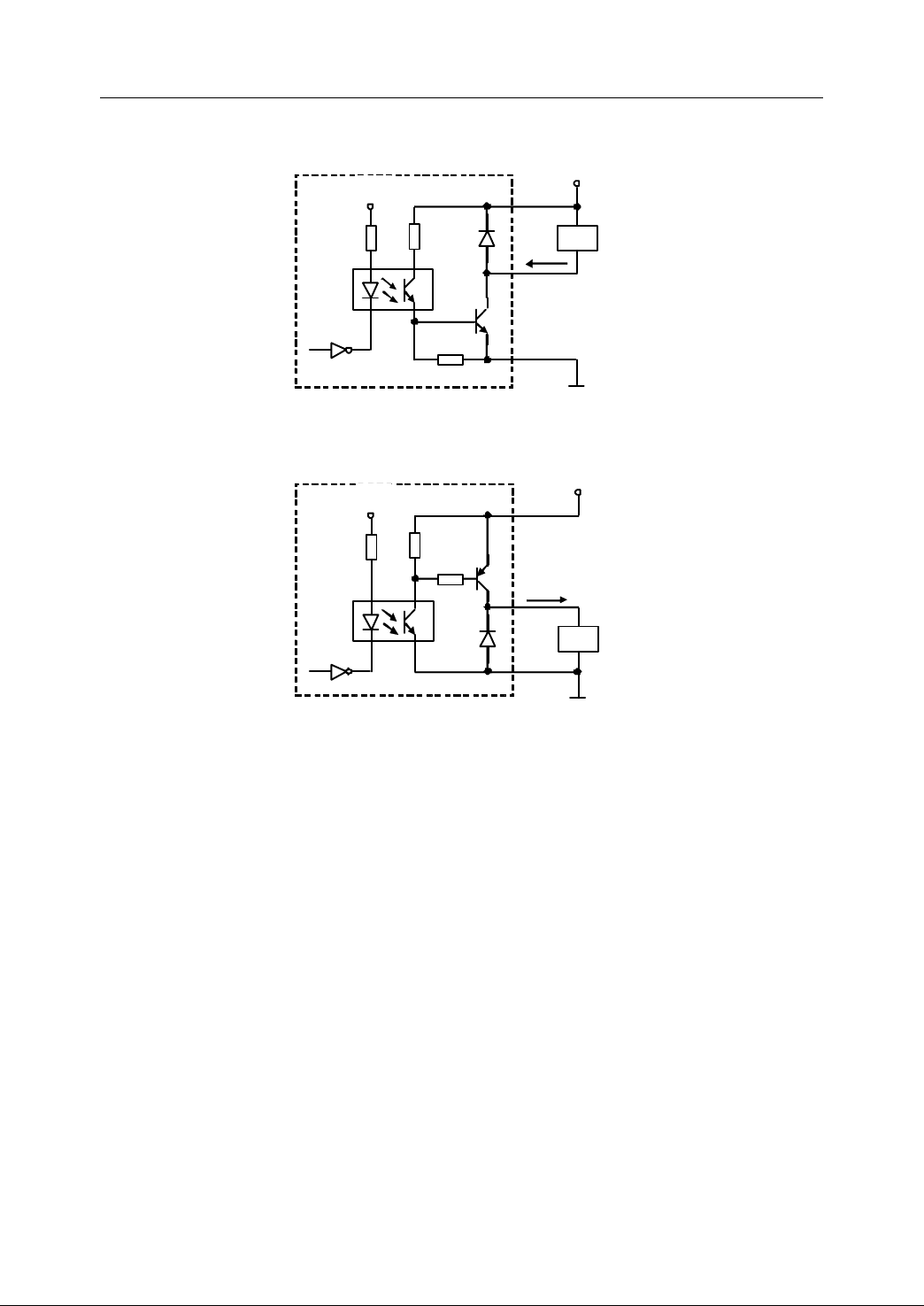
(1) E quivalent circuit
- NPN output interface
Figure 2 26 Equivalent circuit of NPN output interface
- PNP output interface
Figure 2 27 Equivalent circuit of PNP output interface
Note
:
Note
:
Note
Note :
:
- The type of the output interfaces on HNC-21/22 unit is NPN.
- The output terminal board includes NPN and PNP input terminal.
(2) T echnical parameters
- The optically coupled technique is adopted. The highest isolated voltage is
2500V RMS (one minute).
- The supply voltage is 24V.
- The maximum output current is 100mA.
(3) Typical application of circuit
- Drive a LED
NPN or PNP output terminal can be used to drive a LED.Aresistance about
28
Page 39
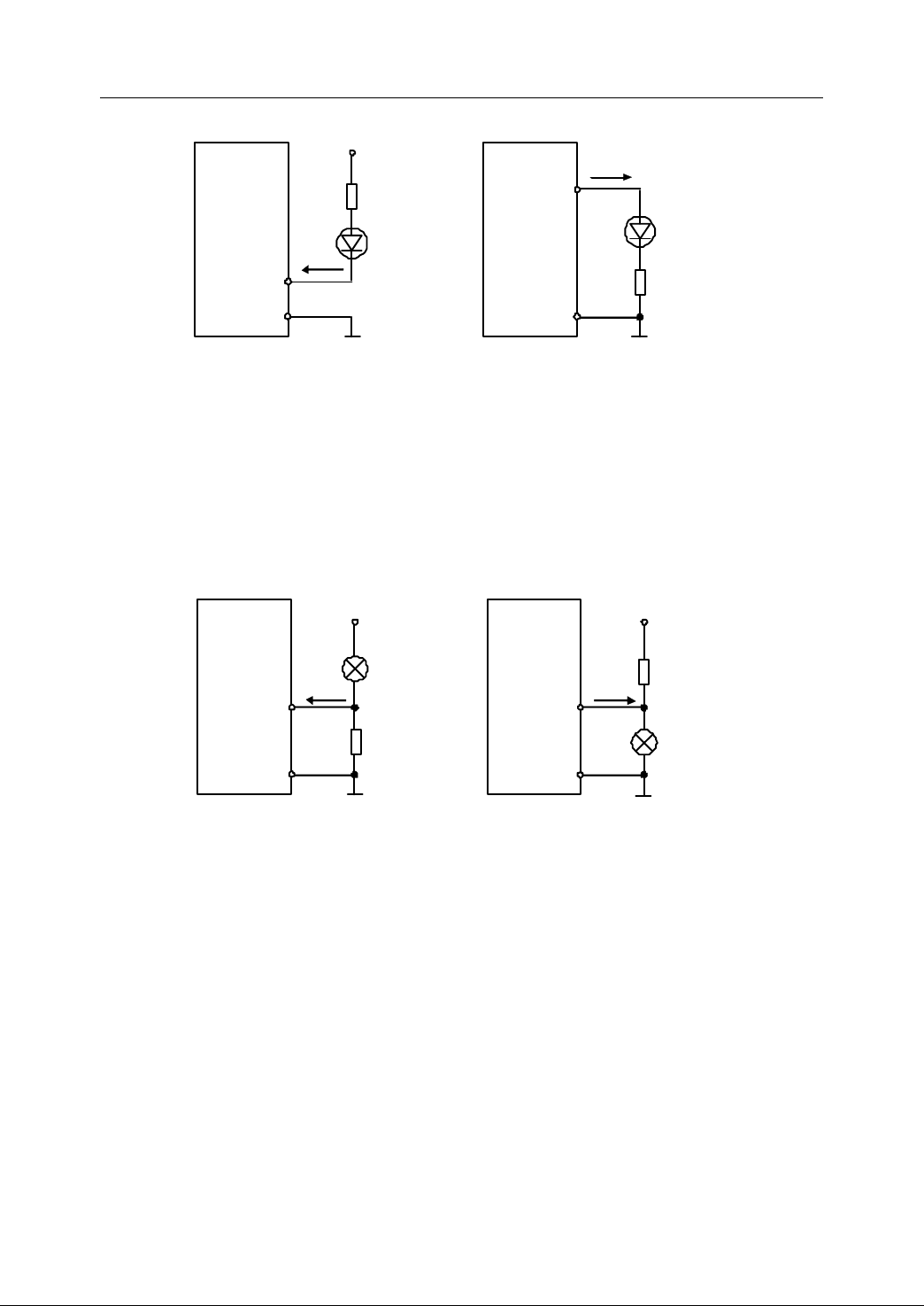
10mA is connected in series to control the current flowing through LED .
IL=10mA
+24V
2.5k
24V
G
ND
a ) NPN output
IL=10mA
P
2.5k
24V G
ND
b
) PNP output
N
+24V
24V
G ND
a ) NPN output
b ) PNP output
N
P
reheating
resistanc e
+24V
24V GND
P
P
reheating
resistance
I L≤1 0
0mA
IL≤
1 0
0mA
Figure 2 28 Using PLC output to drive LED
- Drive a filament pilot lamp
2. Connection
NPN or PNP output terminal can be used to drive a filament pilot lamp.
preheating resistance is required to reduce the current shock while turning
the pilot on . The ohm value of the resist ance should be large enough to
keep the pilot off .
Figure 2 29 Using PLC output to drive a filament pilot lamp
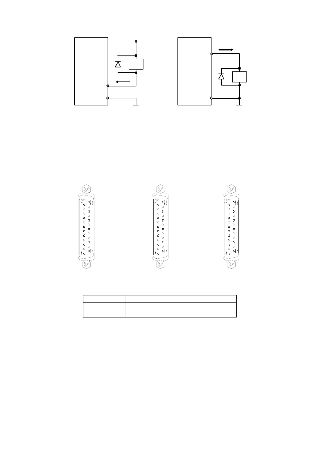
- Drive an inductive load (such as relay)
NPN or PNP output terminal can be used to drive an inductive load.
flywheel diode sh all be connected in parallel with the coil of the relay to
A
A
protect the output circuit from interference (some relays have been
equipped with flywheel diodes) .
Note:
Note:
Note:
Note: The voltage of coil shall be DC24V.
29
Page 40
2. Connection
IL≤ 100mA
+24V
F
lywheel
diode
24V GND
a ) NPN output
IL≤
1
0 0mA
P
24V G
ND
b ) PNP output
N
KA
R elay coil
F
lywheel
diode
KA
R elay c oil
25
:
Y0.1
24
:
Y0.3
23
:
Y0.5
22
:
Y0.7
21
:
Y1.1
20
:
Y1.3
19
:
Y1.5
18
:
Y 1.7
17
:
NC
16
:
NC
15
:
24VG
14
:
24VG
13 :
Y0.0
1 2:
Y0.2
11 :
Y0.4
10 :
Y0.6
9 :
Y1.O
8 :
Y1.2
7 :
Y1.4
6 :
Y1.6
5 :NC
4 :NC
3 :NC
2 :
24VG
1 :
24VG
XS20 (
DB25 PIN
)
25
:
Y 2 .1
24
:
Y 2 .3
23
:
Y 2 .5
22
:
Y 2 .7
21
:
Y 3 .1
20
:
Y 3 .3
19
:
Y 3 .5
18
:
Y 3 .7
17
:
NC
16
:
NC
15
:
24VG
14
:
24VG
13 :Y2 .0
1 2:
Y
2 .2
11 :Y2 .4
10 :Y2 .6
9 :Y3 .O
8 :Y3 .2
7 :Y3 .4
6 :Y3 .6
5 :NC
4 :NC
3 :NC
2 :
24VG
1 :
24VG
XS2
1
(
DB25 PIN
)
25
:
Y 4 .1
24
:
Y 4 .3
23
:
Y 4 .5
22
:
Y 4 .7
21
:
Y 5 .1
20
:
Y 5 .3
19
:
Y 5 .5
18
:
Y 5 .7
17
:
NC
16
:
NC
15
:
24VG
14
:
24VG
13 :Y4 .0
1 2:
Y
4 .2
11 :Y4 .4
10 :Y4 .6
9 :Y5 .O
8 :Y5 .2
7 :Y5 .4
6 :Y5 .6
5 :NC
4 :NC
3 :NC
2 :
24VG
1 :
24VG
XS2
2
(
DB25 PIN
)
Figure 2 30 Using PLC output to drive an inductive load
(4) Pin of PLC output interface
� Output interface on NC device
Figure 2 31 Interface of XS20, XS21 and XS22
Table 2 3 Description of XS20, XS21 and XS22
Signal Description
24VG External switch power DC24V Ground
Y0.0~Y5.7 PLC output (48 bit)
� Interface of output terminal board
30
Page 41
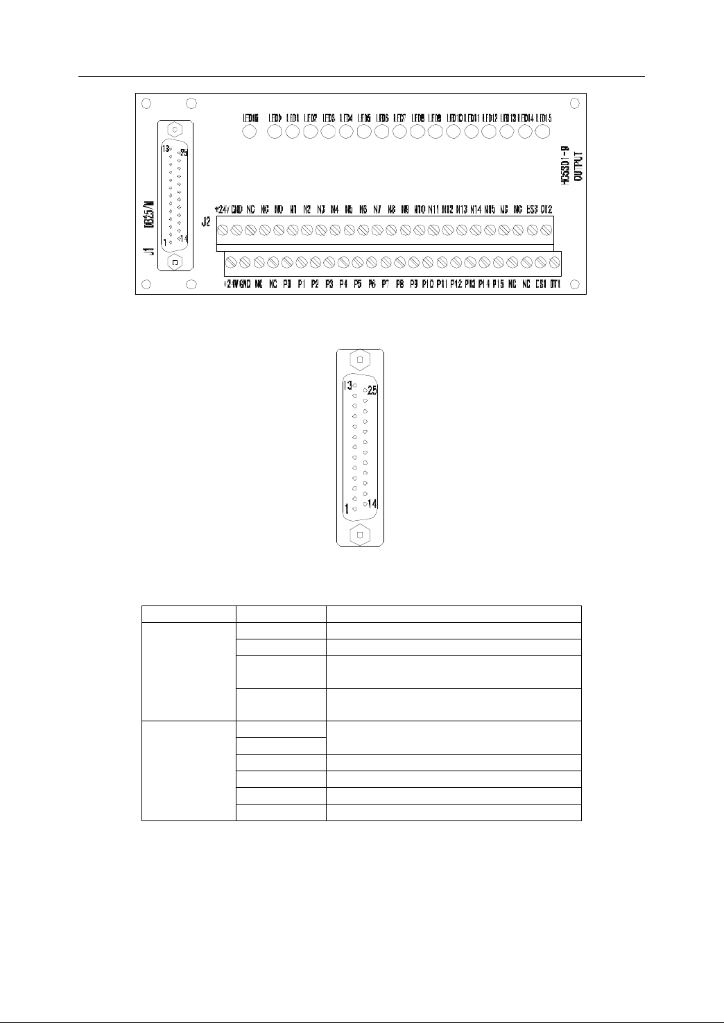
Figure 2 32 Output terminal board
25:NO1
24:NO3
23:NO5
22:NO7
21:NO9
20
: NO1 1
19
: NO1 3
18
: NO1 5
17 : ESTOP3
16
: OTB S2
15
: 24V G
14
: 24V G
13:NO0
12:NO2
11:NO4
10:NO6
9 :NO8
8
: NO1 0
7
: NO1 2
6
: NO1 4
5
: NC
4 : ESTOP1
3
: OTB S1
2
: 24V G
1
: 24V G
J1
(
DB25 /M
PIN
)
2. Connection
Figure 2 33 Interface of J1 on output terminal board
Table 2 4 Description of output J1 and J2
Interface Signal Description
24VG External switch power DC24V Ground
NO0~NO15 PLC output
J1 (DB25/M)
J2
ESTOP1
ESTOP3
OTBS1
OTBS2
+24V
GND
Emergency stop
O vertravel released
External switch power DC24V
NC Not connection
N0~N15 NPN output terminal
ES1, ES3 Emergency stop
P0~P15 PNP output terminal
Note:
Note:
Note:
Note: NPN and PNP can be used on the same bit.
31
Page 42
2. Connection
Cabinet
Cabinet
Cabinet
Cabinet
F
ield on-off input module
~
12
1 , 2 , 14 , 15
24V GND
X0.0 ~
X7.3
4 … 13
16 … 25
HNC -21/22
External supply 2 : +24V
P ower of on - off signal
24V GND
<15 m
C ommon GND
C
C
C
C abinet
abinet
abinet
abinet
XS 2 0~2 2
1 , 2 , 14 , 15
24V GND
Y0.0 ~ Y5.7
6 … 13
1 8 … 25
HNC
- 21
/22
External supply 2 : +24V
P ower of on - off signal
+24V
<15 m
+
+
-
-
P
ilot lamp, relay,etc
External supply +24V
External supply 24V GND
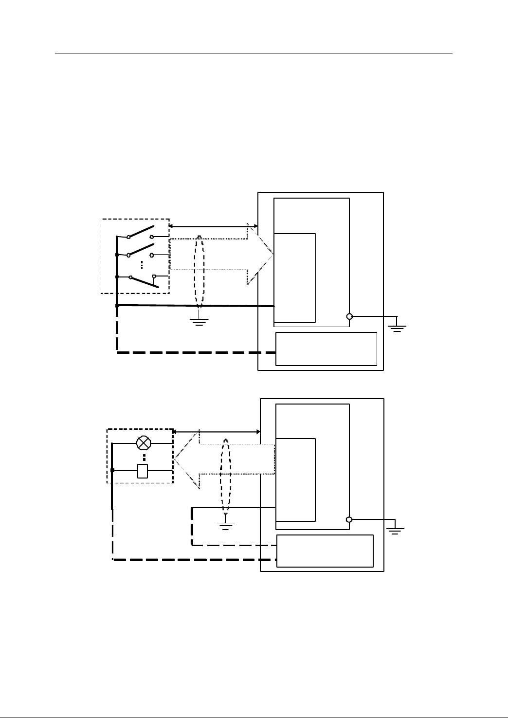
2.6.3
2.6.3
2.6.3
2.6.3 Direct
The external I/O signal can be directly connected to X S 10 , X S
Direct
Direct
Direct Connection
Connection
Connection
Connection to
to
NC
to
NC
to NC
NC device
device
device
device
11
, XS12, XS20, XS21,
or XS22 o f HNC-21 /22. It is widely used when I/O ports are less required and NC
device is installed in the control cabinet. This way of connection is simple and cost
effective . However, i t is not convenient to assemble or disassemble cables , and n o
PNP I/O terminals are available to use.
Figure 2 34 Connection between PLC input and NC unit
Figure 2 35 Connection between PLC output and NC unit
32
Page 43
2. Connection
HNC - 21 /22
XS10
DB25/F
E - stop &
Overtravel
released
XS 11
DB25/ F
DC24V
≥ 50W
XS 12
DB25/ F
XS 20
DB25/ M
On-off outputs
P
P
P
P endant box
endant box
endant box
endant box
Cabinet
Cabinet
Cabinet
Cabinet
XS 21
DB25/ M
XS 22
DB25/ M
On-off input s
≤ 15 m
J1
J2
DB25/F
+24
GND
NC
NC
N 0 ~ N 19
+24
GND
NC
NC
P0 ~ P 19
Input terminal board
NPN
PNP
X0.0 ~ X2.3
≤ 15 m
J1
J2
DB25/F
+24
GND
NC
NC
N0 ~ N 19
+24
GND
NC
NC
P0 ~ P 19
Input terminal board
NPN
PNP
X2.4 ~ X4.7
≤ 15 m
J1
J2
DB25/F
+24
GND
NC
NC
N0 ~ N 19
+24
GND
NC
NC
P0 ~ P 19
I
nput terminal board
NPN
PNP
X5.0 ~ X7.3
≤ 15 m
J1
J2
DB25/ M
Output terminal board
+24
GND
NC
NC
P0 ~ P 1 5
NC
NC
ES1
OT1
+24
GND
NC
NC
N0 ~ N 1 5
NC
NC
ES3
OT2
NPN
PNP
Y0.0 ~ Y1.7
≤ 15 m
J1
J2
DB 25/ M
Output terminal board
+24
GND
NC
NC
P0 ~ P 1 5
NC
NC
ES1
OT1
+24
GND
NC
NC
N0 ~ N 1 5
NC
NC
ES3
OT2
NPN
PNP
Y2.0 ~ Y3.7
≤ 15 m
J1
J2
DB25/ M
Output terminal board
+24
GND
NC
NC
P0 ~ P 1 5
NC
NC
ES1
OT1
+24
GND
NC
NC
N0 ~ N 1 5
NC
NC
ES3
OT2
NPN
PNP
Y4.0 ~ Y5.7
External supply 2
External supply 2
External supply 2
External supply 2
On - off I/O power
+24V
GND
2.6.4
2.6.4
2.6.4
2.6.4 Co
Co
nnection
Co
nnection
Co nnection
nnection to
to
NC
to
NC
to NC
NC device
device
device
device through
through
through
through I/O
I/O
terminal
I/O
terminal
I/O terminal
terminal board
board
board
board
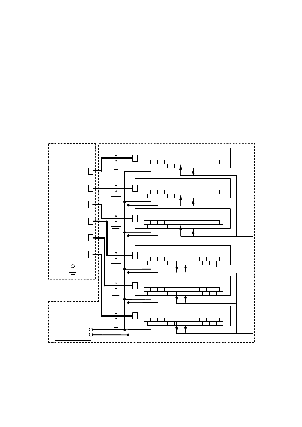
As it is shown in Fig ure 2-36 , XS10 , XS11 a nd XS1 2 of HNC-21/22 are connected to
J1 on the input terminal board, and X S20 , XS21 and XS2 2 are connected to J1 on
the output terminal board. NPN or PNP inputs/outputs are connected to J2 on the
terminal boards.
This way of connection is used when NC device and strong-current circuit are
installed in the different cabinets . I t is convenient for the circuit installation ,
commissioning and maintenance .
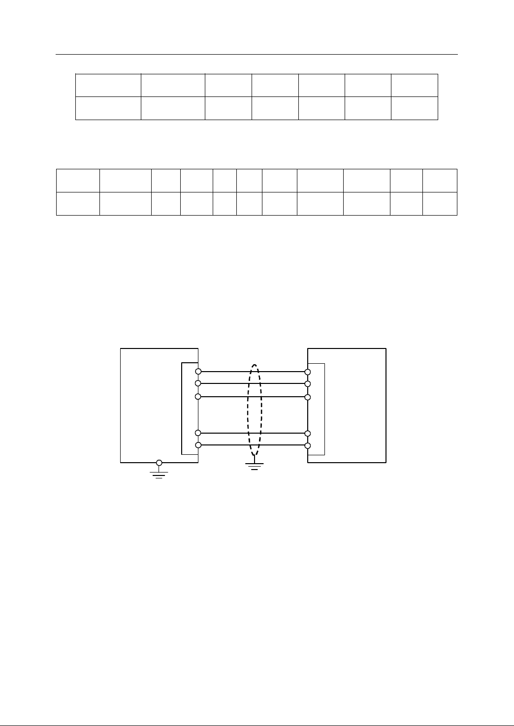
The relationship between J1 and J2 on the input terminal board is shown as below:
Figure 2 36 Connection to NC device through I/O terminal board
33
Page 44
2. Connection
……
……
……
……
1
2
J1
1
2
3
3
……
……
……
……
24
25
24
25
≤ 15 m
XS10 ~ XS12
XS20 ~ XS2 2
HNC - 21 /22
Terminal board
……
……
……
……
Table 2 5 Relationship between J1 and J2 on the input terminal board
J1 DB25 PIN
J2 GND
24VG
(1,2,14,15)
NI0
(13)
N0
P0
NI1
(25)
N1
P1
…… NI18
……
N18
P18
NI19
(4)
(16)
N19
P19
The relationship between J1 and J2 on the output terminal board is shown as below:
Table 2 6 Relationship between J1 and J2 on the input terminal board
J1DB25
PIN
J2 GND
24VG
(1,2,14,15)
NO0
(13)
N0
P0
NO1
(25)
N1
P1
…
NO14
…
…
…
NO15
(6)
(18)
N14
P14
N15
P15
ESTOP1
(4)
ES1 ES3 OT1 OT2
ESTOP3
(17)
OTBS1
(3)
OTBS2
(16)
Each PLC input/output on terminal board contains both NPN and PNP terminal and
its LED to make the commissioning and fault detection easier.
The following figure shows the c onnection between J1 on I/O terminal board and
XS10, XS11, XS12, XS20, XS21 , and XS22 of HNC-21/22.
Figure 2 37 Connection between I/O terminal board and NC device
2.6.5
2.6.5
2.6.5
2.6.5 Description
Description
Description
Description of
of
PLC
of
PLC
of PLC
PLC Address
Address
Address
Address
In NC system, PLC inputs are defined as X , and the PLC outputs are defined asY.
One byte is composed of 8 bits. For the information about I/O interface (XS10, XS11,
XS12, XS20, XS21, XS22) of HNC-21/22, please refer to the chapter 2.6.1 and
2.6.2.
The following table shows PLC inputs/outputs of HNC-21/22.
34
Page 45
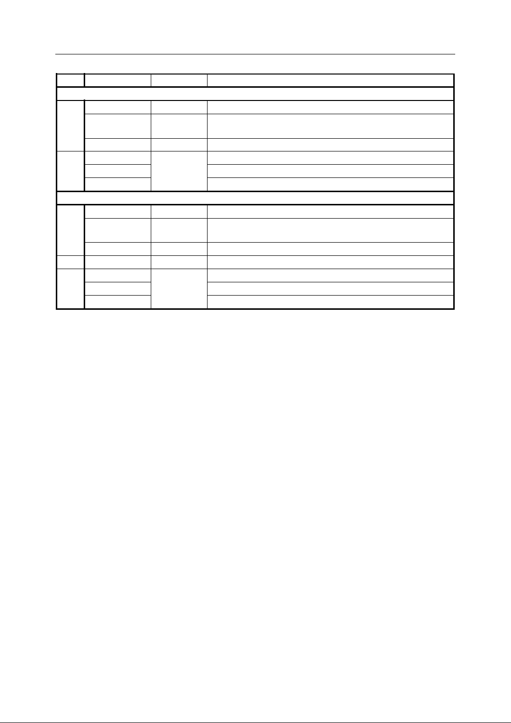
Table 2 7 PLC inputs/outputs of HNC-21/22
No. X/Y address Interface Descriptions
PLC inputs
PLC inputs
PLC inputs
two interfaces of X4.0~X4.7 are connected in parallel.
PLC inputs
inputs for the button at the first row of MCP
inputs for the button at the second row of MCP
inputs for the button at the third row of MCP
1
2
X0.0 ~ X2.3
X2.4 ~ X4.7
X5.0 ~ X7.3
X30.0 ~ X31.6
X32.0 ~ X33.5
X34.0 ~ X35.6
XS10
XS11 , XS8
XS12
MCP
PLC outputs
PLC out puts
PLC outputs
two interface of Y3.4~Y3.7 are connected in parallel.
PLC outputs
Spindle analog voltage outputs
outputs for the pilot of button at the first row of MCP
outputs for the pilot of button at the second row of MCP
outputs for the pilot of button at the third row of MCP
1
2
3
Y0.0 ~ Y1.7
Y2.0 ~ Y3.7
Y4.0 ~ Y5.7
Y28.0 ~ Y29.7
Y30.0 ~ Y31.6
Y32.0 ~ Y33.5
Y34.0 ~ Y35.6
XS20
XS21 , XS8
XS22
XS9
MCP
2. Connection
35
Page 46
2. Connection
14 : 24V G ND
15 : 24V G ND
16 : + 24V
17 : ESTOP3
18 : X4.7
19 : X4.5
20 : X4.3
21 : X4.1
22 : Y3.7
23 : Y3.5
24 : HA
25 : + 5V
1
13
14
25
1 : 24VG
2 : 24VG
3 : + 24V
4 : ESTOP2
5 : NC
6 : X4.6
7 : X4.4
8 : X4.2
9 : X4.0
10 : Y3.6
11 : Y3.4
12 : HB
13 : 5V G
XS8 ( DB25 PIN )
2.7
Connection
2.7
Connection
2.7
2.7 Connection
Connection to
to
Handwheel
to
Handwheel
to Handwheel
Handwheel Unit
Unit
Unit
Unit
2.7.1
2.7.1
2.7.1
2.7.1 Handwheel
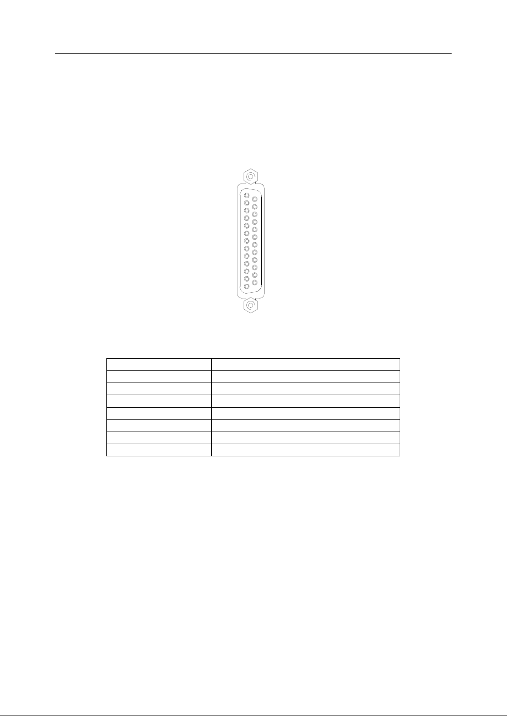
Handwheel unit is connected to HNC-21/22 by XS8 (DB25 pin).
Handwheel
Handwheel
Handwheel Interface
Signal Description
+24V, 24V G ND P ower supply DC24V
ESTOP2 , ESTOP3 Emergency stop on the handwheel unit
X4.0 ~ X4.7 I nputs on the handwheel unit
Y3.4 ~ Y3.7 O utputs on the handwheel unit
HA P hase
HB P hase B on the handwheel unit
+5V , 5V G ND Handwheel power supply DC5V
Interface
Interface
Interface
Figure 2 38 Interface of XS8
Table 2 8 Interface description of XS8
A
on the handwheel unit
The inputs/outputs of axis selection, override selection, enab le button, and pilots of
handwheel unit are on X4.0
handwheel unit .
Notes:
Notes:
Notes:
Notes: If no handwheel unit is used or there is no emergency stop button on the
handwheel unit, pin 4 and pin 17 of XS8 shall be short circuited by DB25 male plug .
36
X4.7 ( 8 bits ) and Y3.4
~
Y3.7 ( 4 bits ) of XS8 on the
~
Page 47

2. Connection
2.7.2
2.7.2
2.7.2
2.7.2 Connection
Connection
Connection
Connection to
to
Standard
to
Standard
to Standard
Standard Handwheel
Handwheel
Handwheel
Handwheel Unit
Unit
Unit
Unit
T he interface of standard handwheel unit provided by our company is DB25 pin,
which can be directly connected to XS8 on HNC-21/22 device. The following table
shows I/O interface for the handwheel unit on HNC-21/22.
Table 2 9 I/O interface for the handwheel unit on HNC-21/22
Pin Signal Description
13 5V GND
25 +5V
12 HB Phase B from MPG
24 HA Phase
11
23 Y3.5 Undefined (Reserved for the pilot of feed hold button)
10 Y3.6 P ilot lamp of handwheel unit
22 Y3.7 U ndefined
9 X4.0 Axis selection: X
21 X4.1 Axis selection: Y
8 X4.2 Axis selection: Z
20 X4.3 Axis selection: 4
7 X4.4 Override selection: X1
19 X4.5 Override selection: X10
6 X4.6 Override selection: X100
18 X4.7 Undefined
5 NC
17 ESTOP3
4 ESTOP2
3,16 +24V
1,2,14,15 24V G ND
Y3.4 Undefined ( Reserved for the pilot of cycle start button )
Power supply DC5V for MPG on the handwheel unit
It
is
provided
It
is
provided
It
It is
is provided
provided by
A
P in of emergency stop (ESTOP) button on the handwheel unit
(Pin
4
and
(Pin
4
(Pin 4
4 and
is
provided
It
is
provided
It is
is provided
provided by
and
and 17
(Pin
Power supply DC24V for some modules of the handwheel unit
It
It
by
by
by HNC-21/22.
from MPG
17
should
17
should
17 should
should be
by
by
by HNC-21/22.
HNC-21/22.
HNC-21/22.
HNC-21/22.
be
short
be
short
be short
short circuited,
HNC-21/22.
HNC-21/22.
HNC-21/22.
circuited,
circuited,
circuited, if
if
there
if
there
if there
there is
is
no
ESTOP
is
no
ESTOP
is no
no ESTOP
ESTOP button.)
button.)
button.)
button.)
If the handwheel unit is not used , pin 4 (ESTOP2) and pin 17 (ESTOP3)
of XS8 should be short circuited by DB25 male plug. Otherwise, the re
would be an alarm message caused by the non-working emergency stop
button on the machine control panel of NC unit . For more detailed
information, please refer to chapter 2.10.
37
Page 48
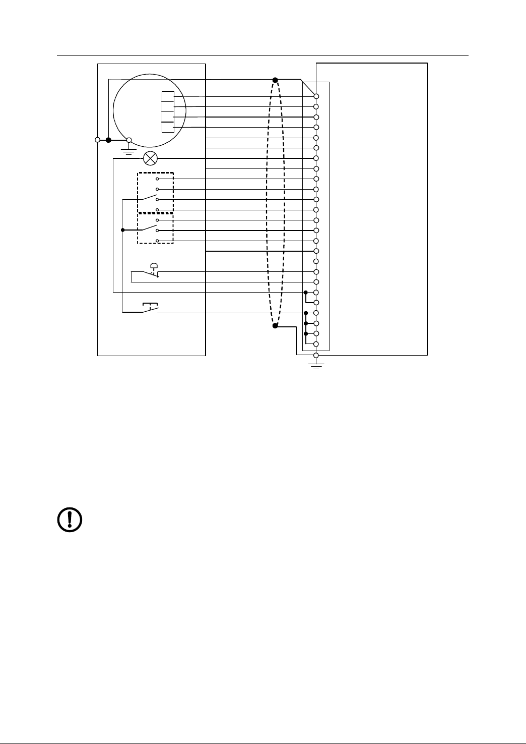
2. Connection
24V G ND
ESTOP 2
+24V
H B
+5V
+5V GND
A
pi lot
Axis X
Axis Y
Axis Z
4th axis
X1
X10
X100
HNC - 21 /22
Handheld unit
XS 8
1 3 5VG
25 +5V
1 2 HB
24 HA
1 1 Y3.4
23 Y3 .5
1 0 Y3.6
22 Y3.7
9 X4.0
21 X4.1
8 X4.2
20 X4.3
7 X4.4
1 9 X4.5
6 X4.6
1 8 X4.7
5 NC
1 7 ESTOP3
4 ESTOP2
1 6 +24V
3 +24V
1 5 24V G ND
2 24V G ND
1 4 24V G ND
1 24V G ND
+5V
GND
A
B
MPG
ESTOP
X
Y
Z
4
X1
X10
X100
Axis
override
Enabled
pilot
ESTOP 2
PE
X P8
Figure 2 39 Connection to Standard Handwheel Unit
2.7.3
2.7.3
2.7.3
2.7.3 Connection
Connection
Connection
Connection to
to
Customized
to
Customized
to Customized
Customized Handwheel
Handwheel
Handwheel
Handwheel Unit
Unit
Unit
Unit
Please r efer to I/O design of the standard handwheel unit (such as axis selection,
override selection, and pilot lamps etc), while customizing a handwheel unit.
If there is no emergency stop button on the handwheel unit , pin 4
(ESTOP2) and pin 17 (ESTOP3) of XS8 should be short circuited by
DB25 male plug. Otherwise, there would be an alarm message caused
by the non-working emergency stop button on the machine control panel
of NC unit. For more detailed information, please refer to chapter 2.10 .
The type of I/O is NPN with DC24V. Please refer to section 2.6.
The specification of MPG (Manual Pulse Generator) is DC5V, TTL level,
phase-A output, and phase-B output.
38
Page 49
2. Connection
15 : GND
14 : AOUT2
13 : 5VG
12 : +5V
11 : SZ -
10 : SB -
9 : SA -
8 : GND
7: GND
6 : AOUT1
5 : 5VG
4 : +5V
3 : SZ+
2 : SB+
1 : SA+
XS9 ( DB15 PIN )
2.8
Connection
2.8
Connection
2.8
2.8 Connection
Connection to
Different kinds of spindle can be connected to HNC-21/22 by XS9 to implement CW
rotation, CCW rotation, spindle orientation, speed regulation etc. Spindle encoder
can also be connected to implement threading of turning and grid tapping of milling.
to
Spindle
to
Spindle
to Spindle
Spindle device
device
device
device
2.8.1
2.8.1
2.8.1
2.8.1 Relevant
2.8.1.1
2.8.1.1
2.8.1.1
2.8.1.1 Spindle
As it is shown in Figure 2-40, XS9 includes the spindle speed analog voltage outputs
and spindle encoder feedback inputs.
Relevant
Relevant
Relevant Interfaces
Spindle
Spindle
Spindle Interface
Signal Description
SA+ , SA- Spindle encoder phase A
SB+ , SB- Spindle encoder phase B
SZ+ , SZ- Pulse Z of spindle encoder
+5V , 5VG P ower supply: DC5V
AOUT1 S
AOUT2
GND
Interfaces
Interfaces
Interfaces
Interface
Interface
Interface XS9
XS9
XS9
XS9
Figure 2 40 Interface of XS9
Table 2 10 Description of XS9
pindle analog output: -10V~ +10V
S pindle analog output: 0~ +10V
A nalog output grounding
The characteristics of signals:
- Spindle speed analog voltage signal
V
oltage: AOUT1: -10V~+10V
AOUT2: 0V~+10V
L oad current: max.10mA
- Spindle encoder interface
39
Page 50
2. Connection
P ower supply: +5V, max.200mA
Encoder signal: RS422 level
E nsure the type of spindle analog output interface, before it is connected
to the spindle frequency converter drive or spindle servo drive . If it is
-10 V ~ +10V, AOUT1 (pin 6) and GND should be used. If it is AOUT2 (pin
14) and GND should be used.
2.8.1.2
2.8.1.2
2.8.1.2
2.8.1.2 I/O
PLC inputs/outputs are required to control spindle start -up and stop , receive signals
about the various st atus and alarm messages, when the spindle device is connected
to NC unit .
The definitions of PLC inputs/outputs relevant to spindle control are listed as below,
which would be mentioned in the typical design (Chapter 5).
I/O
related
I/O
related
I/O related
related to
S ignal
Spindle gear 1 X2.0 X2.0
Spindle gear 2 X2.1 X2.1 17
Spindle gear 3 X2.2 4
Spindle gear 4 X2.3 16
Spindle alarm X3.0 X3.0
Spindle speed arrived X3.1 X3.1 23
Zero spindle speed X3.2 10
S pindle orientation X3.3 22
System rest Y0.1 Y0.1
Spindle enable Y0.3 Y0.3 24
Spindle CW rotation Y1.0 Y1.0 9
Spindle CCW rotation Y1.1 Y1.1 21
Spindle mode switch/brake Y1.2 Y1.2 8
Spindle orientation Y1.3 20
Spindle gear 1 Y1.4 Y1.4 7
Spindle gear 2 Y1.5 Y1.5 19
Spindle gear 3 Y1.6 6
Spindle gear 4 Y1.7 18
to
Spindle
to
Spindle
to Spindle
Spindle
Table 2
11
I/O related to spindle control
Register X/Y
Milling Turning
Inputs
Outputs
Interface P in
XS10
XS11
XS20
5
11
25
2.8.2
2.8.2
2.8.2
2.8.2 Spindle
The spindle start and stop are controlled by PLC. The following table shows I/O
40
Spindle
Spindle
Spindle Start
Start
Start
Start and
and
Spindle
and
Spindle
and Spindle
Spindle Stop
Stop
Stop
Stop
Page 51

2. Connection
related to spindle start and stop in the standard PLC of milling and turning.
Table 2 12 I/O related to spindle start and stop
Signal
Spindle speed arrived X3.1 X3.1
Zero spindle speed X3.2 10
Spindle enable Y0.3 Y0.3
Spindle CW rotation Y1.0 Y1.0 9
Spindle CCW rotation Y1.1 Y1.1 21
Y1.0 and Y1.1 are to control spindle CW/CCW rotation and stop. Usually, they are
set as on. If Y1.0 is on, the operator can control the spindle CW rotation. If Y1.1 is on,
the spindle CCW rotation can be controlled. If none of them is on, the spindle stops
rotation. Y1.0 and Y1.1 are used as the enable signal of spindle unit, when some
spindle frequency converter or spindle servo is used .
The direction of some spindle rotation depends on the polarity (positive/negative) of
Register X/Y
Milling Turning
Inputs
Outputs
Interface P in
XS11
XS20
23
24
spindle speed signal. I n this case, spindle CW signal can be used as spindle enable
control, and the spindle CCW signal is not used.
Some spindle unit contains spindle speed arrived and zero spindle speed, so that
they are used to monitor the spindle rotation by PLC.
Y0.3 can be used, when the individual spindle enable (enable control) is required.
2.8.3
2.8.3
2.8.3
2.8.3 Spindle
As it is shown in Table 2-4, AOUT is to control spindle revolution. The output range is
0V~+10V. Y0.2 and Y0.3 control the direction of spindle rotation.
Two analog outputs of XS9 are used to control the spindle speed in HNC-21/22 .
AOUT1( output range: - 10V ~ +10V) is used for spindle motors with drivers or
frequency converters with bipolar speed command input , and the enabl e signal is
used to control spindle start and stop. Another output, AOUT2 (output range: 0 ~ +10V)
Spindle
Spindle
Spindle Speed
Speed
Speed
Speed Control
Control
Control
Control
is used for those driver units or frequency converters with unipolar speed command
41
Page 52
2. Connection
input , and spindle CW and CCW rotation signals are used to control the spindle CW
and CCW rotation, respectively.
The corresponding spindle speed control signals in register are Y[28] and Y[29].
Y[28] is lower 8 bits, and Y[29] is higher 8 bits. In PLC program, the data from the
register are transferred to analog voltage signal by D/A circuit, and outputted through
pin 6, 7, 8, 14, and 15 of XS9 (pin 7, 8, and 15 are GND).
The correspondence between Y[ 28], Y[29] ( digital value) and analog voltage is
shown as below:
Table 2 13 Correspondence between outputs of digital value ( hex ) and analog voltage
Digital
Analog voltage
P in 6 -10V ~ 0V 0V ~ +10V
Pin 14 0V ~ +5V +5V ~ +10V
2.8.4
2.8.4
2.8.4
2.8.4 Spindle
There are three ways to control the spindle orientation .
1. Use a spindle motor with driver including spindle orientation function.
Spindle
Spindle
Spindle Orientation
The relevant input/output signals were defined in standard milling machine PLC
program as listed below.
Signal Register X/Y (milling) Interface Pin
Spindle orientation
done
Spindle orientation Y1.3 XS20 20
T he spindle orientation command is sent by PLC, i.e. Y1.3 is on. Then, X3.3 is
Orientation
Orientation
Orientation Control
Table 2 14 I/O related to spindle orientation
-0x7FFF ~ 0x0000
( -32767 ~ 0 )
Control
Control
Control
Inputs
X3.3 XS11 22
O utputs
0x0000 ~ 0x7FFF
( 0 ~ 32767 )
sent back after the spindle orientation is done.
2. Use a spindle servo, working in positioning mode .
T he spindle is controlled as the spindle servo. I t can be positioned at any angle
by writing PLC program.
42
Page 53
3. Use the mechanic method .
Depending on the different situation, operators can define the related PLC I/O
by themselves and write PLC programs.
2. Connection
2.8.5
2.8.5
2.8.5
2.8.5 Spindle
Spindle gear can be controlled by PLC. The following table shows I/O related to
spindle gear control in the standard PLC of milling and turning.
When spindle frequency converter or spindle servo is employed, the value of spindle
speed command (analog voltage) should be set in PLC program depending on
different gears .
Spindle
Spindle
Spindle Gear
Signal
Spindle gear 1 OK X2.0 X2.0
Spindle gear 2 OK X2.1 X2.1 17
Spindle gear 3 OK X2.2 4
Spindle gear 4 OK X2.3 16
Spindle gear 1 Y1.4 Y1.4
Spindle gear 2 Y1.5 Y1.5 19
Spindle gear 3 Y1.6 6
Spindle gear 4 Y1.7 18
Gear
Gear
Gear Control
Control
Control
Control
Table 2 15 I/O related to spindle gear control
Register X/Y
Milling Turning
Inputs
O utputs
Interface Pin
XS10
XS20
5
7
When the turning machine is at manual gear control mode, the current spindle gear
should be automatically set, by the actual spindle rotation from spindle encoder in
PLC program, to regulate the spindle speed command (analog voltage) .
As for automatic spindle gear control , please refer to PLC Programming Manual.
The
relevant
The
relevant
The
The relevant
relevant PLC
functions
functions
functions
functions .
2.8.6
2.8.6
2.8.6
2.8.6 Connection
The spindle encoder can be connected by XS9 to implement thread cutting, tapping
etc. Two types of output of spindle encoder can be connected: one type of output is
the difference TTL square-wave , and the other type of output is single-polar TTL
square-wave .
Connection
Connection
Connection to
PLC
PLC
PLC programs
.
.
.
programs
programs
programs are
to
Spindle
to
Spindle
to Spindle
Spindle Encoder
are
required
are
required
are required
required to
Encoder
Encoder
Encoder
to
support
to
support
to support
support the
the
above
the
above
the above
above mentioned
mentioned
mentioned
mentioned
43
Page 54
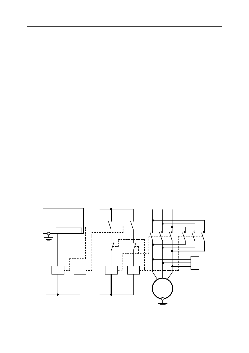
2. Connection
Contact power
HNC-21/22
XS20
U
V
W
O8
O9 Y1.
0 Y1.1
KA3
KA4 +24V
KM3
KM4
Contact power
U11
V11
W11 U1
V1
W1
S
pindle motor
RC1
Arc extinguisher
Generally , the difference encoder is recommended to ensure the reliability of
long-distance transmission and anti- interference ability . For the detailed connection,
please refer to Figure 2-44.
The specification of spindle encoder:
- P ower: +5V (within 200mA, use external power supply if it is higher than 200mA)
- TTL level output
- Difference outputs: A, B, Z
The co m monly used spindle encoder is: LEC- □ BM-G05D ( L, H )
2.8.7
2.8.7
2.8.7
2.8.7 Connection
If AC induction motor without regulation device is taken as spindle motor, the
auxiliary relay and contact are controlled by the outputs of NC device. T hen, the
spindle rotation (CW and CCW) and stop can be controlled. As it is shown in Figure
2-42, KA3 and KM3 are to control the motor CW rotation. KA4 and KM4 are to
control the motor CCW rotation.
Spindle gear can be added to implement step speed r egulation. An external spindle
encoder can be used to implement thread cutting or grid tapping .
Note:
Note:
Note:
Note: The single-phase arc-extinguisher of contact is not shown in the figure.
Connection
Connection
Connection Example
Example
Example
Example ―
―
AC
―
― AC
Induction
AC
Induction
AC Induction
Induction Motor
Motor
Motor
Motor
Figure 2 41 Connection example — Three-phase AC Induction Motor
44
Page 55
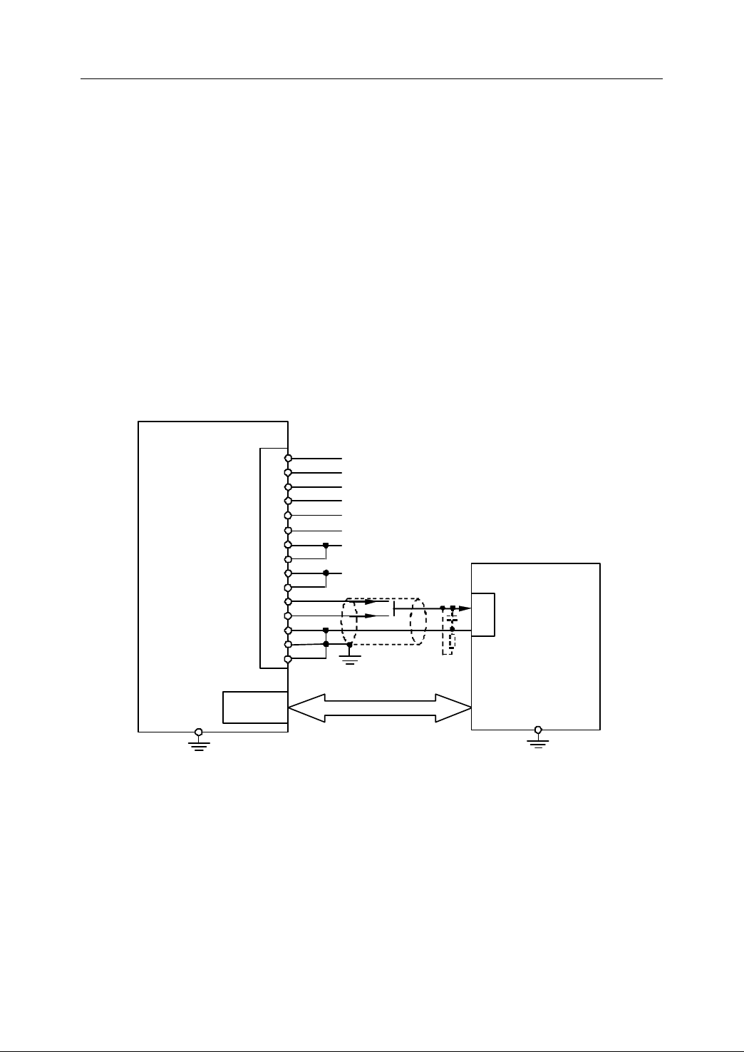
2. Connection
AOUT1
AOUT2
GND
GND
GND
HNC -21/22
XS
9
6
14
7 15
8
I/O
C
ontrol and st atus feedback
Such as spin dle C W/CCW rotation,
spin
dle speed arrived, alarm, etc.
XS 10 ~ XS1 2 ,XS20 ~ XS2 2
PE
Spindle motor
with drive unit
S peed control interface
-10~ +10 V
or
0~+10V
S
peed
control
signal
10
~ +1 0V
0
~ +1 0V
SZ-
+5V
+5V
GND
GND
11
4
12
5
13
SA+
SA-
SB+
SB-
SZ+
1
9
2 10
3
<15m
PE
2.8.8
2.8.8
2.8.8
2.8.8 Connection
Connection
Connection
Connection Example
Example
Example
Example ―
―
Spindle
―
Spindle
― Spindle
Spindle motor
motor
motor
motor with
with
with
with driver
driver
driver
driver
Generally, the servo drive includes AC frequency converter and spindle amplifier.
The non-step spindle regulation can be done within the reasonable range. AOUT on
XS9 is used to define the speed of spindle motor with driver. Spindle start and stop
(or CW and CCW rotation) can be controlled by I/O (XS20, XS21).
If AC frequency converter spindle is used, a mechanical gear can be used to get a
better low speed-torque and a broader speed regulation. For more detailed
information, please refer to chapter 2.8.5.
If the spindle amplifier is used, a broader speed regulation and a better low
speed-torque can be got.
Figure 2 42 Connection to spindle motor with driver – without feedback
As it is shown in Figure 2-44, the spindle speed/position information feedback from
the spindle motor with driver unit (Figure 2-43) or an external encoder (Figure 2-44)
to XS9 on NC unit can be used for thread cutting or tapping .
45
Page 56
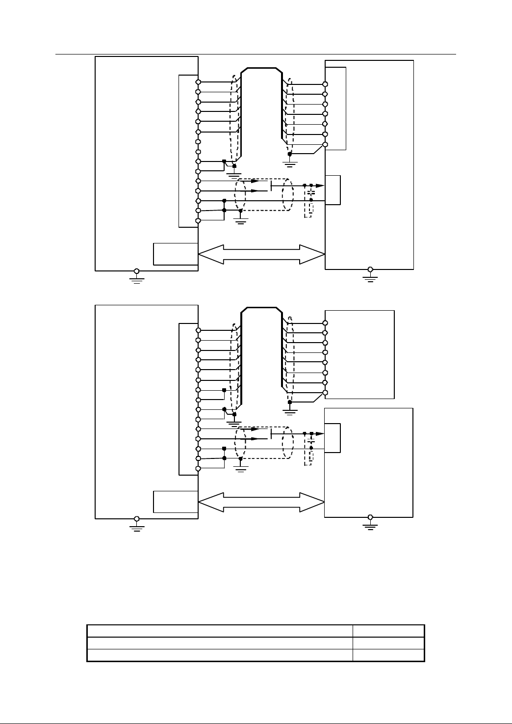
2. Connection
AOUT1
AOUT2
GND
GND
GND
HNC-21 /22
XS
9
6
14
7 15
8
I/O
C o ntrol a nd status feedback
Such as s pindl e CW /CCW rotation,
spindle speed arrived, alarm, etc.
XS 1 0 ~ XS1 2 ,XS20 ~ XS2 2
PE
Spindle motor
with drivers
S
peed control interface
-10~ +
10V
or
0~+10V
S
peed
control
signa l
10
~ +
10V
0~+10V
SZ -
GND
GND
11
4
12
5
13
SA+
SA -
SB+
SB -
SZ+
1
9
2 10
3
Z-
0V
A+
A-
B+
B-
Z+
SZ -
GND
SA+
SA -
SB+
SB -
SZ+
F
eedback
interface
<15m <15
m
PE
PE
AOUT1
AOUT2
GND
GND
GND
HNC-21 /22
XS
9
6
14
7 15
8
I/O
C
ontrol and status feedback
Such as spindl e CW/ CCW rotation,
spindle speed a rrived, alarm, etc.
XS 10 ~ XS1 2 ,XS20 ~ XS2 2
PE
Spindle motor
with drivers
S
peed con trol in terface
-10~ + 10V
or
0
~ +1 0V
S
peed
control
signal
10
~ +1 0V
0
~ +1 0V
SZ-
+5V
+5V
GND
GND
11
4
12
5
13
SA+
SA-
SB+
SB-
SZ+
1
9
2 10
3
Z-
+5V
0V
A+
A-
B+
B-
Z+
SZ -
+5V
GND
SA+
SA -
SB+
SB -
SZ+
S pindle
encoder
<15m <15m
PE
PE
Figure 2 43 Connection to spindle motor with drivers - feedback from spindle motor
Figure 2 44 Connection to spindle motor with drive – feedback from external spindle
2.8.9
2.8.9
2.8.9
2.8.9 Parameters
Parameters
Parameters
Parameters related
The parameters related to spindle device are in machine parameters:
Parameters Value
S pindle encoder revolution 1024
D irection of spindle encoder ( 32 : positive, 33 : negative) 32/33
46
encoder
related
related
related to
to
Spindle
to
Spindle
to Spindle
Spindle device
device
device
device
Page 57

2. Connection
47
Page 58
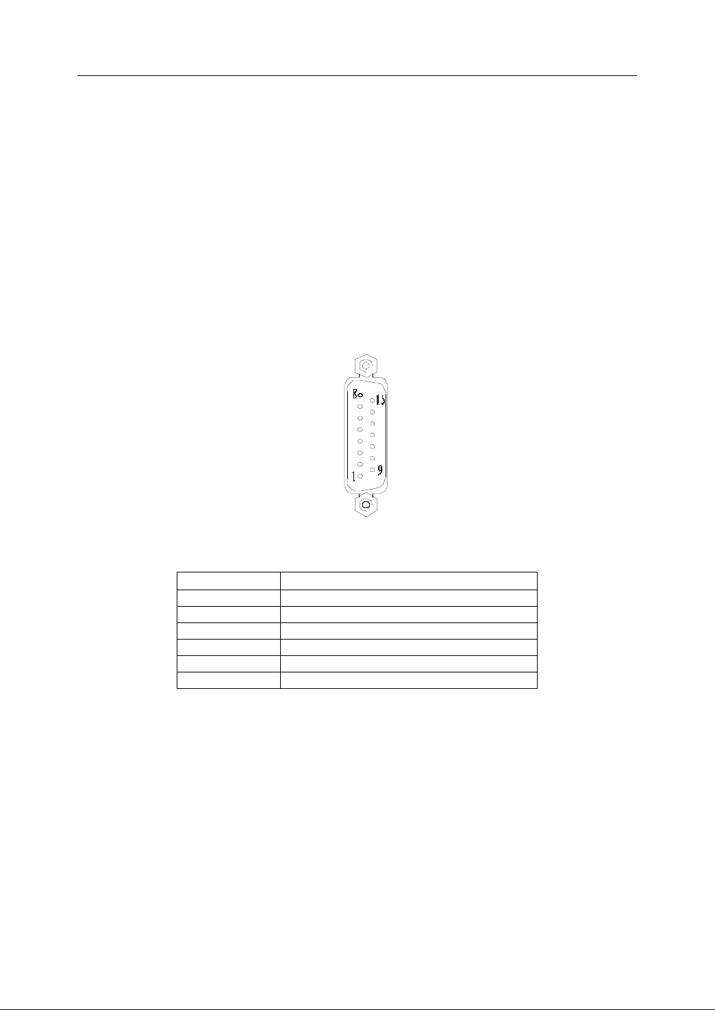
2. Connection
15
:
DIR+
14
:
CP+
13
:
GND
12
:
+5V
11
:
Z -
10
:
B -
9
:
A -
8 :
DIR
-
7:
CP
-
6 :NC
5 :
GND
4 :
+5V
3 :Z+
2 :B+
1 :A+
XS30 ~ XS3
5
( DB 15
)
2.9
Connection
2.9
Connection
2.9
2.9 Connection
Connection to
HNC- 21/22 units use the pulse axis control interface with pulse+direction,
bidirectional pulse, or hermite pulse, and feedback interface to control the servo
drive and step drive unit with pulse command.
to
Feed
to
Feed
to Feed
Feed Drive
Drive
Drive
Drive
2.9.1
2.9.1
2.9.1
2.9.1 Interface
There are six pulse axis interfaces (XS30~ XS3 5) on HNC-21/22.
(1) Signal Definition
Interface
Interface
Interface Description
Description
Description
Description
Figure 2 45 Interface of XS30~XS35
Table 2 16 Description of XS30~XS35
Signal Description
A+, A- feedback signal of encoder phase A
B+, B- feedback signal of encoder phase B
Z+, Z- feedback signal of encoder pulse Z
+24V, 24VG Power : DC 5 V
CP+, CP- command pulse output (phase A)
DIR+, DIR- command directional output (phase B)
(2) T echnical Specification
- Maximum pulse frequency: 800KHZ
- Power supply of encoder: +5V@150mA
- Encoder signal: RS422 level
(3) E quivalent circuit
- Pulse command output
48
Page 59
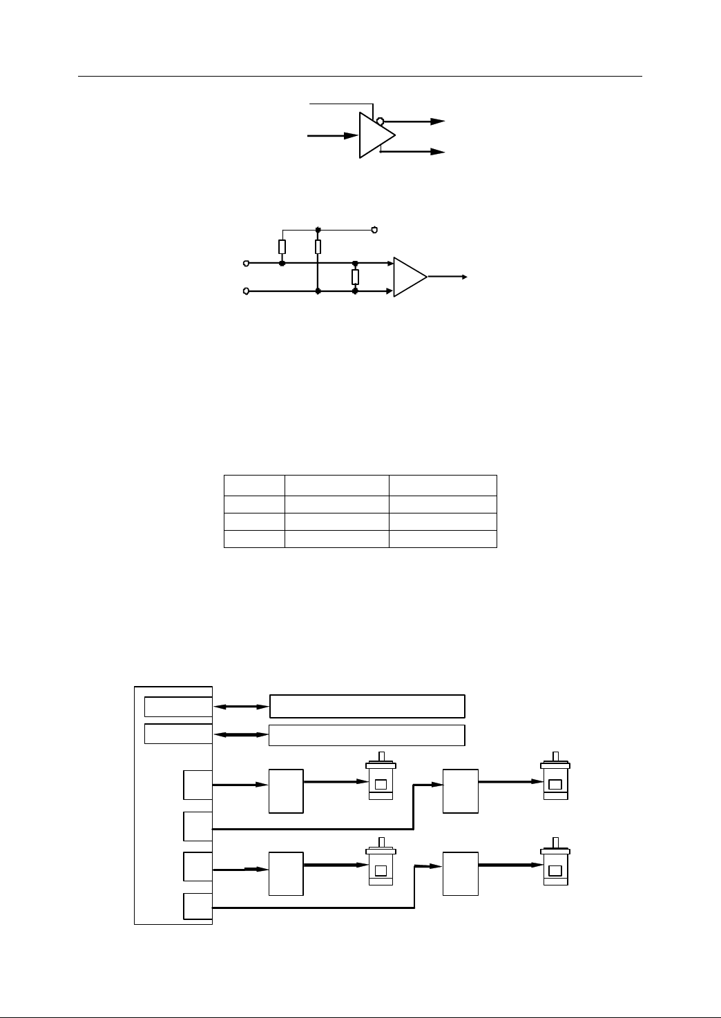
2. Connection
VCC
CP(DIR
)
CP
- (
DIR-)
CP+(DIR+)
+5V
A+
(
B+ , Z+)
A(B , Z )
100
+
-
10K
10K
A -
( B-, Z-)
XS30
XS2 0 ~ X S22
XS1 0 ~ X S12
Outputs (status information of dr iver)
Inputs (status in formation of d rive r )
XS31
XS32
XS33
HNC - 21/22
S
tepper motor
1
S tepp er d rive 1
M otor power
S
tepper motor
3
S tep per m otor 2
S te pper driv e 2
Motor power
Stepp er m otor 4
S tep per d rive 3
M otor power
S tepper drive 4
M ot or power
pulse
pulse
pulse
pulse
Figure 2 46 Equivalent circuit of pulse command output
- Encoder feedback Input
Figure 2 47 Equivalent circuit of encoder feedback input
(4) Pulse type
The type of pulse output (pulse+direction, bidirectional direction, and alternating
pulse) can be set by parameters. For more detailed information, please refer to
Chapter 3.
Table 2 17 Pulse Type
CP DIR
mode 1 pulse direction
mode2 positive pulse negative pulse
mode3 phase A phase B
2.9.2
2.9.2
2.9.2
2.9.2 Connection
Connection
Connection
Connection to
to
Stepper
to
Stepper
to Stepper
Stepper Motor
Motor
Motor
Motor Drive
Drive
Drive
Drive Unit
Unit
Unit
Unit
Up to six step motor drives can be connected to HNC-21/22 through XS30~XS35.
Figure 2-48 shows the overall connection to stepper motor drives. Figure 2- 49
shows an example of the connection to SH-50806A (five phases step motor)
49
Page 60
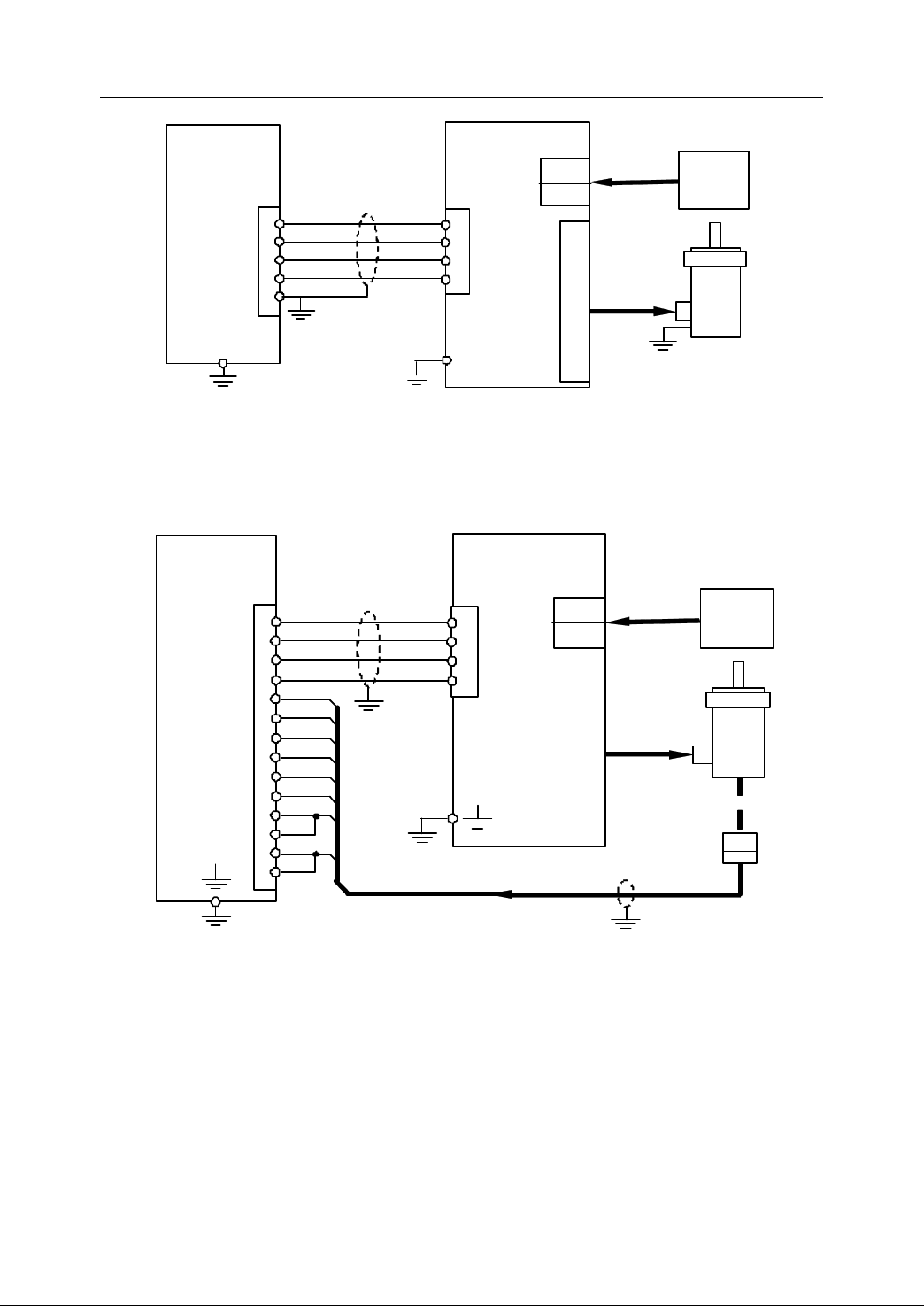
2. Connection
CP+
CP -
DIR+
HNC - 21/22
XS 30 — XS35
14
7
15
CNI/F
Steppe r drive unit
Steppe r drive unit
Steppe r drive unit
Steppe r drive unit
3
4
5
CW+
CW-
CCW+
Shielding
D rive transformer
AC 1P
380/ 80
M otor power
D rive power
S tepper motor
DIR -
8
6
CCW -
AC80
AC80
A +
A -
B+
B -
C+
C -
D+
D -
E+
E -
FG
SH-50806A
13
GND
CP+
CP -
DIR+
-
21 /22
XS
30
~ XS35
14
7
15
CNI/F
Stepper drive
Stepper drive
Stepper drive
Stepper drive
unit
unit
unit
unit
3
4
5
CW +
CW -
CCW+
Shielding
D rive
transformer
AC 1P
380/80
M otor power
Encoder feedback
D r ive power
S tepper
motor
DIR-
A+
A
-
8
1 9
6
CCW-
B+
B
-
Z+
2 10
3
Z
-
+5V
11 12
AC80
AC80
A +
A -
B+
B -
C+
C -
D+
D -
E+
E -
FG
SH-50806A
+5V
4
GND
5
GND
1
3
O ptical
encoder
Shie lding
SH - 50806A
Figure 2 48 Overall connection to stepper motor drive
Figure 2 49 Connection to SH-50806A (five-phase stepper drive unit)
If it is required, an external encoder is used to be a closed loop to prevent the
step-out of stepper motor.
If I/O signals are used in stepper drive unit, the detailed connection can be referred
to the relevant manual of drive unit. I f DC24V is an independent power supply, it
shall be grounded with DC power of I/O. An auxiliary relay is required if I/O interfaces
of step motor drives and NC unit’s are not matched.
When using stepper drive unit, the related parameters are shown as below (for
detailed information, please refer to Chapter 3 and Chapter 4).
50
Figure 2 50 the closed loop between NC unit and stepper drive unit
Page 61
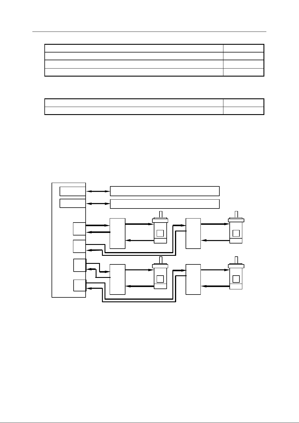
- Servo parameters
XS30
XS20~ XS22
XS10~ XS12
Output s (se rvo contr ol signal , axi s br ake c ontrol)
Inputs (
S ta tus infor matio n of serv o )
XS31
XS32
XS33
HNC - 21/22
S
ervo motor
1
S
ervo drive
1
M otor power
E ncoder
feedback
Servo motor
3
S ervo driv e 3
Motor power
E ncoder
feedback
S
ervo
motor 2
S
ervo driv e 2
M otor power
Encoder
feedback
S erv o mo tor
4
Servo dr ive
4
M otor power
E ncoder
feedback
P ulse
P osition feedback
P ulse
P ulse
P ulse
P osition
P osition
Position
2. Connection
Parameters
Parameters
Parameters
Parameters Value
Value
Value
Value
Servo Type (45: with feedback, 46: without feedback) 46
Stepper motor pulses ≥ 4
Stepper motor (1: yes, 0:no) * 1
- Machine parameters
Parameters
Parameters
Parameters
Parameters Value
Value
Value
Value
Pulse output (0: uni-direction; 1: bi-direction; 2: p hase AB) 0 /1/2
2.9.3
2.9.3
2.9.3
2.9.3 Connection
Connection
Connection
Connection to
to
Servo
to
Servo
to Servo
Servo with
with
with
with pulse
pulse
pulse
pulse command
command
command
command
Up to six servos can be connected to HNC-21/22 through pulse interface of
XS30~XS35. Figure 2-51 is the overall connection between NC device and servo
with pulse command. Figure 2-52 and 2-53 are the two examples of connection to
servo with pulse command.
Figure 2 51 Overall connection between NC device and Servo with pulse command
The following list is the basic conceptions related to servo with pulse command:
1. Position closed loop is constructed within servo driver rather than NC device .
2. Position feedback signals of pulse interfaces are only used for position
monitoring, not for position closed loop .
3.
To
construct fully closed loop control, a servo driver with fully closed loop
51
Page 62
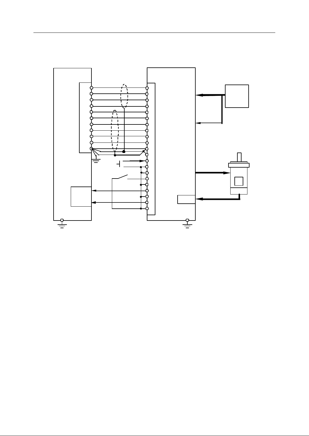
2. Connection
CP+
CP -
DIR+
HNC-21 /22
XS 30~XS35
14
7
15
CNI/F
Servo drive unit
Servo drive unit
Servo drive unit
Servo drive unit
3
4
5
PULS+
PULS-
SIGN+
Shielding
DC24V
Inputs
XS 1 0 ~ XS 12
Servo
transformer
AC 3P
380/200
M otor power
E
ncoder
feedback
Servo power
S ervo motor
DIR-
A+ A-
8
1
9
6
21
22
SIGN-
OA+
OA -
B+
B-
Z+
2
10
3
48
49
23
OB+
OB -
OZ+ Z-
GND
11
13
24
13
OZ -
GND
S ervo control power
L1
L2
L3
r
t
U
V
W
PE
CN SIG
7 8
9
29
34
35
36
37
41
COM+
CCWL
SRV - ON
SRV-RDY+
ALM+
ALM -
COM -
SRV-RDY
-
CWL
25
+24V
24V GND
E nab led
relay
Panasoni c
MSDA10
3D 1A
Panasonic
MS
M A10
2D
1 C
≤ 15 m
*
Notes
interface is necessary .
4. For the parameters of s ervo dri ve unit, please r efer to the related manuals of the
servo driver .
Notes:
Notes:
Notes:
Notes:
Signal ready (SRV-RDY -, SRV-RDY+) and signal alarm (ALM-, ALM+) are closed,
when the drive unit is working normally. I f the signal is the relay terminal output in the
drive unit, the same kind of signals of several drive units are connected in series.
Then, it only takes one bit of PLC input.
For the treatment about “ fault chain ” during the connection of servo drive unit, please
refer to chapter 5.2.4.4.
52
Figure 2 52 Connection to Panasonic MINASA
Page 63
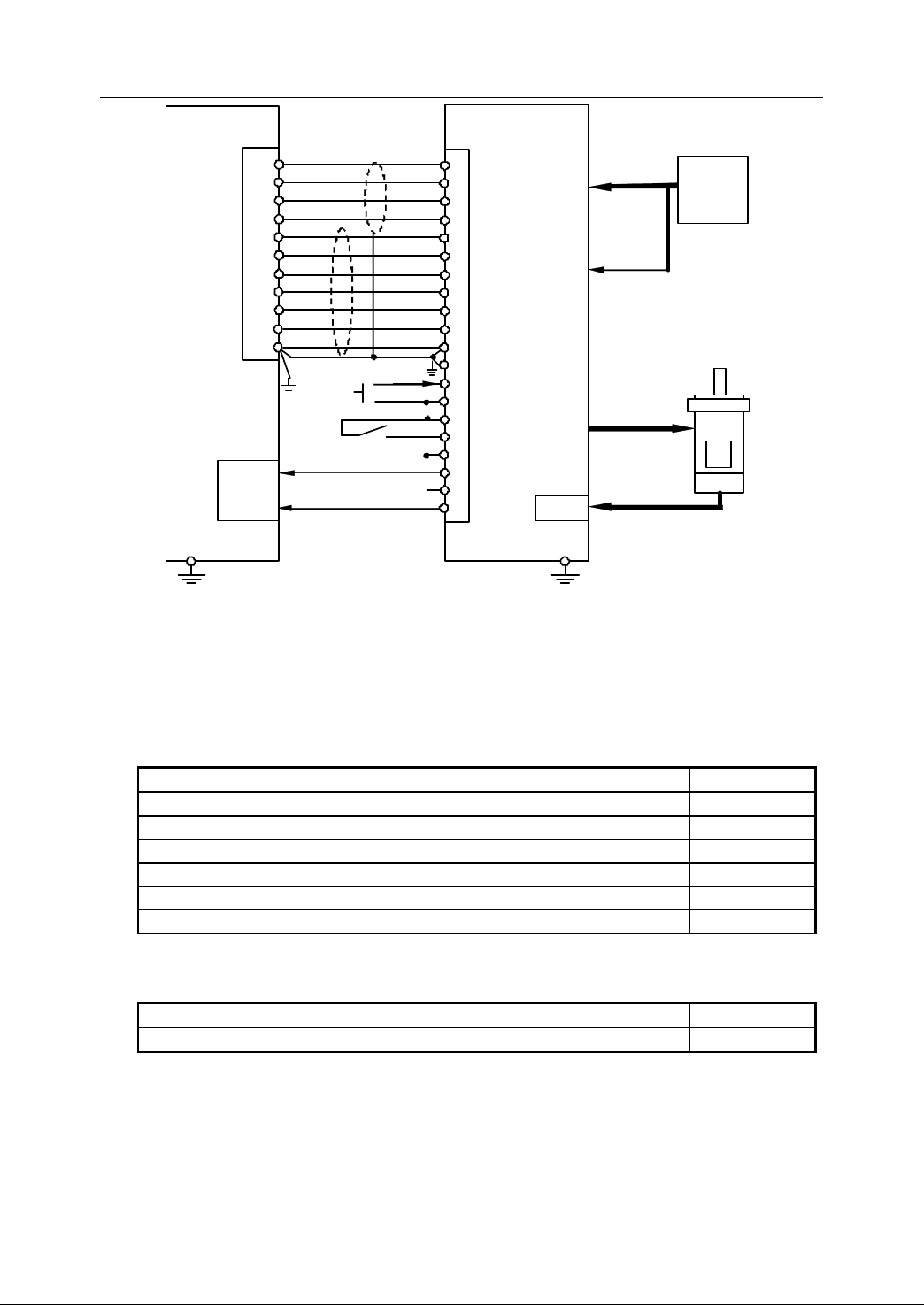
2. Connection
CP+
CP -
DIR+
HNC-21 /22
XS 30~XS35
14
7
15
1CN
Servo drive unit
Servo drive unit
Servo drive unit
Servo drive unit
7
8
11
PULSE
*PULSE
SIGN
Shielding
DC24V
Inputs
XS 1 0 ~ XS 12
S ervo
transformer
AC 3P
380/200
M otor power
E ncoder
feedback
S ervo power
S ervo motor
DIR-
A+
A-
8
1
9
12
33
34
* SIGN
PAO
*PAO
B+
B-
Z+
2
10
3
35
36
19
PBO
*PBO
PCO
Z-
GND
11
13
20
1
*PCO
SG
R
S
T
PE
r
t
U
V
W
PE
2CN
47
42
43
40
30
29
32
31
+24V N- OT S- ON
SRV-RDY+
ALM+
ALM -
SRV-RDY
-
P
- OT
50
+24V
24V GND
E nabl ed relay
Yasuka wa
SGDB-30ADG
Yasukawa SGMG
- 30A2 ABG
18NM
no keys
≤ 15 m
* Note
Servo rea dy
S er
vo alarm
S ervo con tr ol power
Figure 2 53 Connection to Yasukawa SGDB
The parameters related to servo drive unit are shown as below (for more detailed
information, please refer to Chapter 3 and Chapter 4).
-
Servo
-
Servo
-
- Servo
Servo parameters
parameters
parameters
parameters
Parameters
Parameters
Parameters
Parameters Value
Value
Value
Value
Servo Type (45: with feedback, 46: without feedback) 45
Motor revolution 2500
Stepper motor pulses 0
E-gear(NC) 1
E-gear(Servo) -1
Stepper motor (1: yes, 0:no) 0
-
Machine
-
Machine
-
- Machine
Machine parameters
Parameters
Parameters
Parameters
Parameters Value
parameters
parameters
parameters
Value
Value
Value
Pulse output (0: uni-direction; 1: bi-direction; 2: p hase AB) 0 /1/2
53
Page 64
2. Connection
2.10
2.10
2.10
2.10 Design
There is an E-stop (emergency stop) button on both machine control panel of
HNC-21/22 and handwheel unit.
- I t is used to s top NC machine immediately or turn off the main supply of power
- E-stop button shall be pressed, if there is an alarm message. Do not release
There is an overtravel released button on the control panel of HNC-21/22. It is used
to release the overtravel, if the overtravel limit switch is pressed.
No. Signal S ignal description Interface P in I nterface
Design
Design
Design of
devices (such as servo drivers), if there is an emergency .
E-stop button until the alarm has been fixed. This E-stop button and one
normally open contact of auxiliary relay controlled by related circuits should be
connected to the inputs of HNC-21/22, so that the system reset signal can be
used.
Table 2 18 Signals related to E-stop and overtravel released.
of
E-Stop
of
E-Stop
of E-Stop
E-Stop and
and
and
and Overtravel
Overtravel
Overtravel
Overtravel Released
Released
Released
Released
description
I nterface
type
1 ESTOP2
2 ESTOP3
3 ESTOP1 4
4 OTBS1
5 OTBS2 16
It is recommended to use the design of the internal and external circuit (Figure 2-54).
In the following figure, t he bold lines show the emergency stop circuit, while the thin
lines are the overtravel rel eased circuit. KA is a n auxiliary rela
supply for servo , spindle etc . It is suggested that one of the normally open contacts
of KA is connected to PLC input of PLC to produce an external operation enabl e
signal.
E-Stop loop terminal
O vertravel Released terminal
XS8
XS20
4
17
17
3
Handwheel
unit
Y0.0 ~ Y1.7
outputs
y,
controlling the power
DB25
54
Page 65
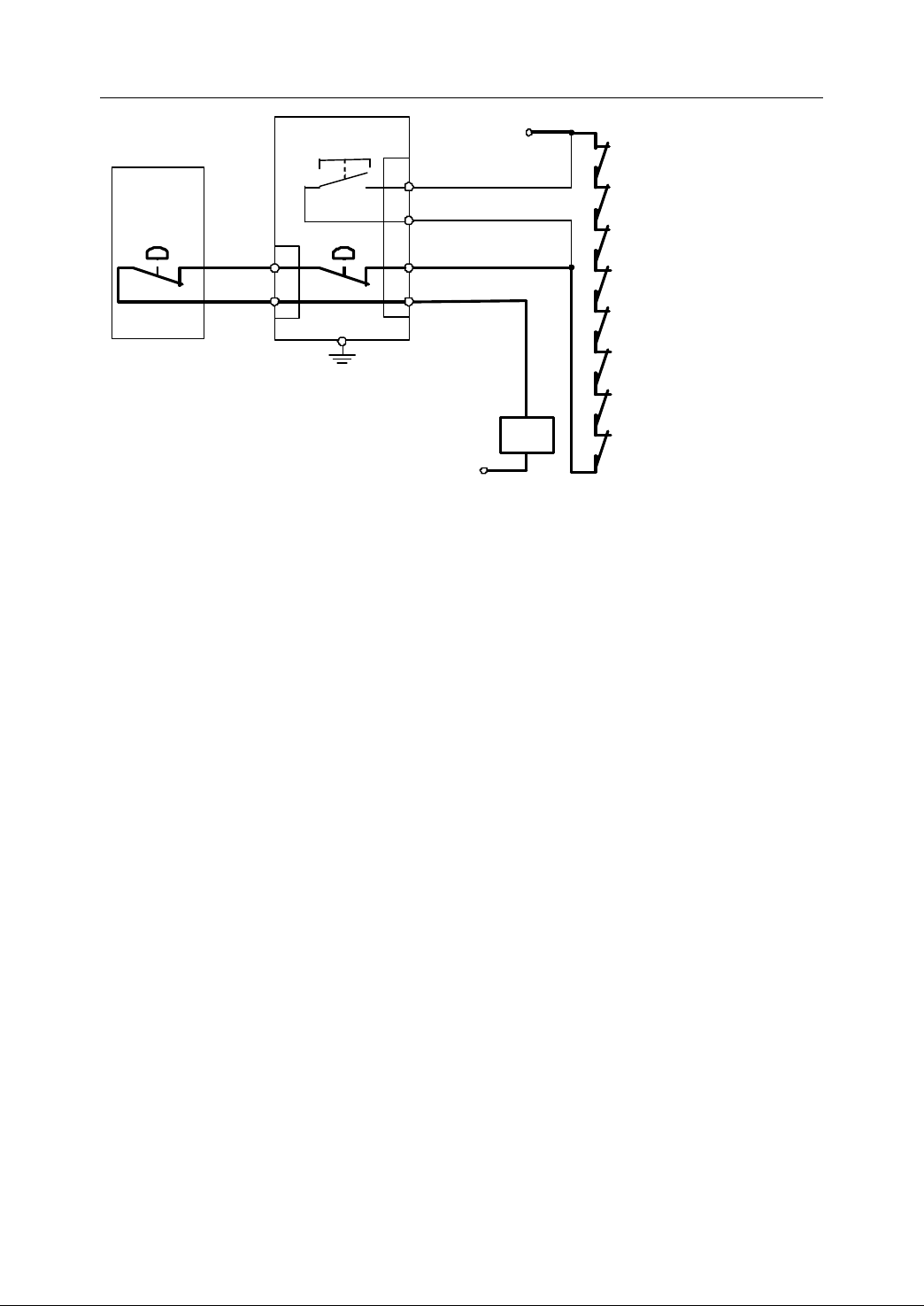
2. Connection
XS 20
4
17
ESTOP3
ESTOP2
HNC - 21 /22
H andheld unit
XS8
4
17
E-stop button
ESTOP3
ESTOP1
E - stop button
3
16
OTBS2
OTBS1
O
vertravel
released
button
24V GND
+24V
Axis1
+
Overtravel limit switch
Axis1 - Ov ertr avel limi t switch
Axis 2+ Overtravel limi t swi tch
Axis 2 - Overtravel limit switch
Axis 3+
Overtra
vel limit switch
Axis 3 - Overtravel limit switch
Axis 4+ Overtravel limit switch
Axis 4 - Overtravel limit switch
KA
Figure 2 54 Recommended connection to E-stop and Overtravel released signal
Except for the emergency stop button from the machine control panel and
handwheel unit, more than one E-stop button can be used if necessary. The
normally closed contacts of each emergency stop button are connected to the
emergency stop circuit in series . Generally, E-stop b uttons are released and its
contacts are closed . While E-stop button is pressed, the contacts are open and the
auxiliary relay (KA) controlled by the emergency stop circuit is turned off. The power
supply of motion components (such as feed motor, spindle motor, tool
magazine/turret motor etc.) is turned off. Meanwhile, a group of normally open
contacts of the auxiliary relay (KA) connected at PLC input send the alarm signal of
emergency stop. This signal is taken as the system reset signal, when the
emergency stop button is on.
In the system, t he normally closed contacts of the positive/negative overtravel limit
switch on each axis are connected to the overtravel loop of NC device in series .
Meanwhile, one normally open contact from each overtravel limit switch is
connected to PLC input. Then, the status of each overtravel limit switch can be
monitored. Generally, the overtravel limit switch is released. If the overtravel limit
switch is pressed by the operator, its normally closed contacts are off, and the
overtravel circuit of NC device is disconnected. Meanwhile, the auxiliary relay (KA)
55
Page 66

2. Connection
of emergency stop circuit is turned off, and the power supply of motion components
is off automatically. The normally open contacts of the overtravel limit switch
connected at PLC input send the overtravel alarm signal to the system (the relevant
axis and the direction of overtravel). And the pilot lamp on the overtravel released
button is on.
If there is an overtravel, same as the emergency stop alarm, the auxiliary relay (KA)
is powered off, and one group of normally open contacts from the auxiliary relay (KA)
would send the emergency alarm signal through PLC inputs. PLC cannot monitor
the normally open contacts of the auxiliary relay (KA), but also the status of normally
open contacts of every overtravel limit switch. Thus, the emergency alarm and the
overtravel alarm can be distinguished.
When the overtravel occurs, NC device are stopped and the system shows the
alarm message.
To
release the overtravel, the following steps can be done:
1) P ress the overtravel released button to reset system. Do not release this button
until the overtravel is released.
2) Press the axis key with the correct direction to release the overtravel limit switch.
Then, the pilot lamp on the overtravel released button is off.
3) Release the button.
Suggestion for design:
PLC programs are required to implement the above mentioned contents such as
system r eset signal, turning on and off the pilot lamp of overtravel rel eased button,
and checking the overtravel axis and its direction. For more detailed information,
please r efer to PLC Design Manual.
When the operator is writing PLC program s, please ensure that the axis would not
move if the overtravel is re leased in the wrong direction . The axis m oves only when
its overtravel is re lease d in the correct direction . O therwise , a serious damage to the
ballscrew w ould happen. For more detailed information, please refer to PLC Design
Manual.
56
Page 67

2. Connection
2.11
2.11
2.11
2.11 Design
NC device shall be accorded with the requirement of electromagnetic compatibility in
JB/T 8832-200 1 ( General requirements for numerical control systems of machine
tools ).
Electromagnetic Compatibility (EMC) refers to
- EMI ( electromagnetic interference ) level of electrical equipments sh all not be
- T he anti-interference ability of device shall be strong enough to e nsure working
2.11.1
2.11.1
2.11.1
2.11.1 EMC
EMC of NC device contains four elements:
- Voltage interruption and Temporary downwards voltage
Design
Design
Design of
higher than the permitted level in the expected working environment .
normally in the expected working environment .
EMC
EMC
EMC of
NC system can work even if one of the following situations happens: AC power
of
Electromagnetic
of
Electromagnetic
of Electromagnetic
Electromagnetic Compatibility
of
NC
of
of NC
Device
NC
Device
NC Device
Device
Compatibility
Compatibility
Compatibility
supply is interrupted for the half of cycle during any cycle; the time of voltage
dr opping is not more than one cycle, and the value is decreased to 40% rating.
- Anti-interference test with high-speed transient pulses
a) NC system can work, even if the peak of voltage pulses of 2KV and the
repetition rate of 5KHz are set between its AC power supply terminal and
the protection grounding.
b) NC system can work, even if the peak of voltage pulses of 1KV and the
repetition rate of 5 KHz are appended to I/O signal cables, data cables and
control cables through coupling clips.
- Anti-interference test with surge voltage
NC system can work even if a surge voltage of 10KV has been appended to AC
power supply, or a surge voltage of 2KV is overlapped across AC supply ground
terminal.
- A nti-interference test with static discharge
NC system can work, even if the touch discharge voltage of 6KV or the air
discharge voltage of 8KV is imposed where the operators often touch.
57
Page 68
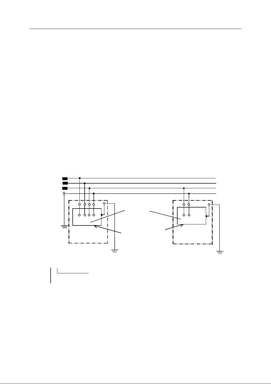
2. Connection
2.11.2
2.11.2
2.11.2
2.11.2 Grounding
There are three kinds of grounding: protection grounding (safety grounding), working
grounding (working grounding), shield grounding (shield grounding).
2.11.2.1
2.11.2.1
2.11.2.1
2.11.2.1 Safety
To
prevent persons and equipments from thunderstroke, electrical leakage, and
static discharge, a ground, called protection ground, is connected to case or chassis.
It should be connected firmly with the real earth. F or the basic requirements of
protection ground , please r efer to Section 8.2 in “ GB5226.1-2008 (Electrical safety
of machinery-Electrical equipment of machines-Part 1: General requirements) ” .
- G rounding type of TT (Figure 2-55) or TN-S (Figure 2-56) is recommended for
machine tool NC systems. TN-C type (Figure 2-57) is not allowed to use.
Grounding
Grounding
Grounding
Safety
Safety
Safety Grounding
Grounding
Grounding
Grounding
L1
L2
L3
PE
Supply
ground
Operator ’ s
electric unit
Ground of electric unit
T T
The outer conductive part of electrical equipment is connected to
ground directly. This ground is independent from the supply ground .
One point of the supply is connected to ground directly.
Figure 2 55 TT type
58
Device in
electric unit
Case or other
conductive part
Operator ’ s
electric unit
Ground of electric unit
Page 69
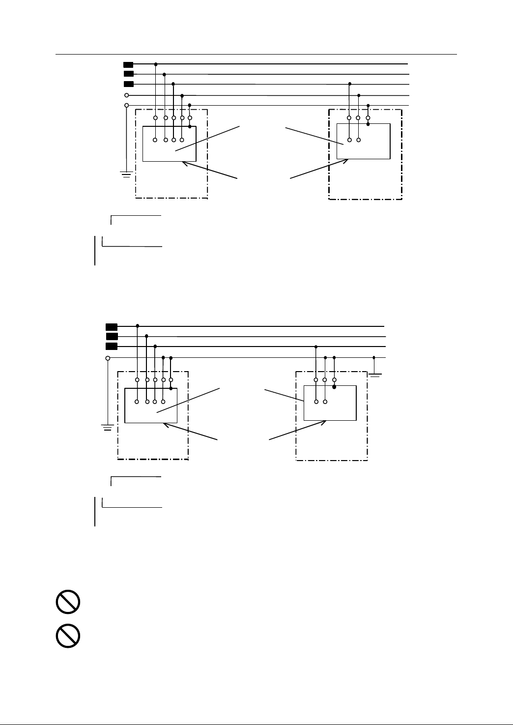
Device in
electric unit
2. Connection
L1
L2
L3
N
PE
Supply
ground
T N-S
One point of the supply is connected to ground directly .
Operator ’ s
electric unit
The neutral is separate from the protection earth (PE) .
The outer conductive part of electrical equipment is connected to
supply ground directly.
Case or other
conductive part
Figure 2 56 TN-S type
Device in
electric unit
Supply
ground
Operator ’ s
electric unit
Case or other
conductive part
Operator ’ s
electric unit
L1
L2
L3
PEN
Grounding
Operator ’ s
electric unit
Note
Note
Note
Note :
The neutral and the protection earth (PE) are combined.
T N- C
The outer conductive part of electrical equipment is connected to
supply ground directly.
One point of the supply is connected to ground directly .
Figure 2 57 TN-C type
:
:
:
It would be better not to lay a neutral in control cabinet. If it is used , identify the
neutral distinctively by N in installation diagrams, in schematic diagrams, and on
terminal boards .
It is not allowed to either co nnect neutral to ground within the control cabinet or
use a common terminal PEN ( it refers to the terminal connecting neutral N to
protection earth PE) .
59
Page 70
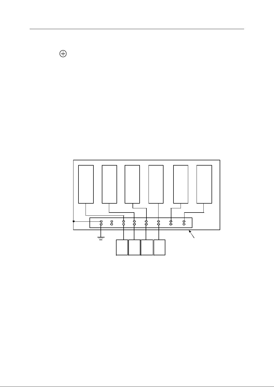
2. Connection
PE
Grounding
bus
X-axis
motor
Control cabinet
Servo supply
源
Servo driver X
Servo driver Y
Servo drive Z
Supply
Transducer
Y
- axis
motor
Z
- axis
motor
Spindle
motor
- Essentials of safety grounding design
a) P rotection ground terminals shall be used in electric unit. It can be marked
as or yellow-green double-colored sign. It is not allowed to r eplac e the
protection ground terminal with a screwed joint on outer case or chassis .
b) T he protection ground terminal shall be connected to case, chassis etc . The
continuity of protection ground circuit sh all be met the criterion of
GB5226.1-2008 Section 8.2.
c)
A
ground ing bus ( the recommended thickness ≥ 3mm copper bar) shall be
connected to earth . T he grounding resistance must be less than 4 Ω .
d) As it is shown in Figure 2-58, the protection ground terminals of electric unit
should be connect ed to the ground bus with the shortest and thickest
yellow-green double-colored wires.
Figure 2 58 Example of Protection Ground
e) Do not loop the protection ground wire . Figure 2-59 and Figure 2-60 show
the correct connection of safety grounding and the wrong connection of
safety grounding, respectively.
60
Page 71
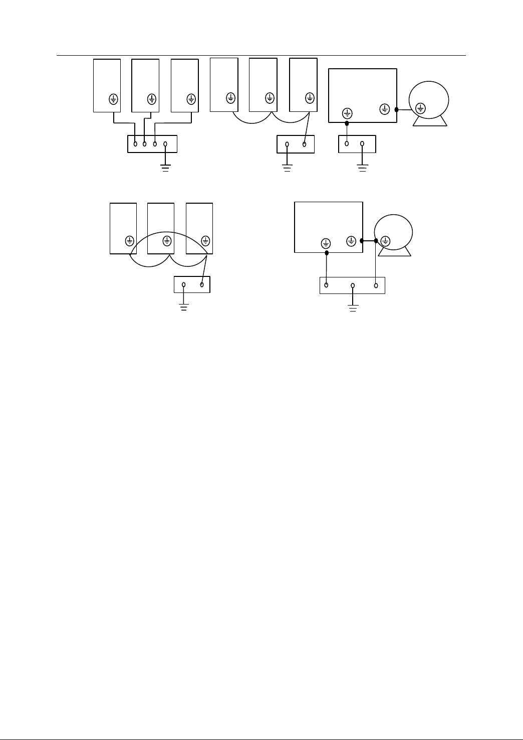
2. Connection
1 2 3
Grounding
bus
Figure 2 59 Correction connection of protection ground
1 2 3
Grounding
bus
Figure 2 60 Wrong connection of protection ground
1 2 3
Grounding
bus
Grounding
Servo drive
(Transducer)
bus
Servo drive
(Transducer)
M
Grounding
bus
M
f) C onnecting the outer case to earth is the most effective measure to restrain
the static discharge interference. In case of discharging, the current flows
along outer case to earth directly, and the internal circuits would not be
affected.
g) Connecting the case to earth plays a role of shielding to reduce the
electromagnetic interference among equipments .
2.11.2.2
2.11.2.2
2.11.2.2
2.11.2.2 Working
Working
Working
Working Grounding
Grounding
Grounding
Grounding
It refers to the reference potential (0V) for electrical signals. The working ground
shall be connected correctly. Otherwise, it would even produce the interference,
such as common ground reluctance interference, ground loop interference,
common-mode current radiation, etc . There are four modes of working grounding:
floating grounding, single-point grounding, multi-point grounding, and mixed
grounding .
- Floating grounding
As it is shown in Figure 2-61, the working ground is insulated from metal case. It
is floated to protect i nternal circuits from external common-mode interference .
61
Page 72
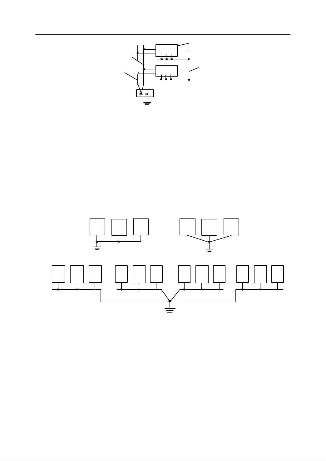
2. Connection
case
case
Working ground
Metallic cover
Protection ground
Shielding ground
1
2
3
1
2
3
Noise ground
Digital ground
1
2 3 1 2
3
1 2
3 1 2
3
Analog ground
Metallic ground
(a) Single - point series (b) Single - point parallel
( c) Single - point mi xed
Figure 2 61 Floating Grounding
- Single-point grounding
Only one physical point is defined as reference ground in single-point grounding.
All other points in the circuit or equipment, which need to be grounded, are
connected to this point . If a system includes many devices, the ground of each
device is independent. The in ternal circuit of every device has its own
single-point ground. Then, the grounds of every device in this system are
connected to the unique r eference point of the system . There are three types of
single-point grounding : series, parallel, and mixed .
Figure 2 62 Single-point Grounding
Single-point grounding is simple and easy to install, and its wiring is similar to
circuit diagram. The drawback is its long ground wire. When system frequency is
rather high, the ground reluctance increases, and the common ground
reluctance interference is produced . Meanwhile , the high frequency
tremendously increases the mutual interference among two grounds, or between
the ground and other wires, induced by capacitive or inductive coupling .
- Multi-point grounding
62
Page 73

2. Connection
Connecting all the grounding points of equipment (or a system) directly to the
nearest grounding plane is referred to as multi-point grounding. It makes ground
wires as short as possible. The equipment chassis, the special ground wire, or
even the frame of the equipment may be taken as the grounding plane .
2 4
1
Figure 2 63 Multi-point Grounding
3
Multi-point grounding is simple to install, and it greatly reduces the
high-frequency stationary wave phenomena appeared in grounding wires.
However, it requires more maintenance on t he wire in grounding loops of
multi-point grounding system. Some factors such as erosion, shock, and
temperature variation would increase the system reluctance and decrease the
grounding effect iveness.
- M ixed grounding
Based on the analysis of system, connect the points which require the nearest
ground ing (or high frequency grounding through by-pass capacitors ) , directly to
the grounding plane. The single-point grounding is used to the rest of points.
- Essentials of working grounding design
a) Do not make any closed loop while designing the ground, because the
closed loop would induce an electromagnetic force (EMF) by the effect of
the external electromagnetic field , and then a current is produced . The
voltage drop of this current on the ground reluctance may result in the
common-reluctance .
b) The isolation measures, such as optoelectrical coupling, isolation
transformer, relay, and common-mode choke, are recommended to cut off
the grounding loops among devices or circuits, and to check the
common-reluctance coupling interference induced by the grounding loops .
c) Each circuit in the equipment, such as analogue circuit, digital circuit, main
circuit, interference circuit etc., sh all be equipped with its own ground
(sub - ground), and connected to the general ground finally .
d) Generally, the l ow frequency circuits (f<1MHz) use dendriform emanant
63
Page 74

2. Connection
single-point grounding. The length of ground wire sh all not be longer than
one twentieth of the wave length of high frequency current of the ground
wire (i.e. λ =c/f, 1< λ <20, c : light speed). For the longer ground, it needs to
make their reluctance, especially inductance, as low as possible, for
example, increase the width of ground wires, use conductors having
rectangular cross section instead of round one as the ground wires, etc .
e) Generally, the h igh frequency circuits (f>1MHz) use multi-point grounding or
mixed grounding. For example, the circuit boards and chassis of industrial
control computer often use multi-point grounding .
f) The floating grounding (working ground is insulated from the metal case) is
only suitable for the small -scale equipments ( the distribution of capacity
between circuits and the case is small ) or the low speed circuits (its
frequency is low) . For the large-scale equipments with complex circuits and
higher frequency, the floating grounding is not used.
g) In case there are a few electrical devices (or electrical units) equipped in the
control cabinet, the working ground, the protection ground, and the shielding
ground are connected to the central ground of the cabinet (grounding bus) .
T hen , they are connected to the earth to keep the cabinet, the devices, the
case, the shield, and working ground at the same potential level .
2.11.2.3
2.11.2.3
2.11.2.3
2.11.2.3 Shield
To
check the interference, the shields of cables and transformers should be
grounded. The relevant ground wires are called shield ground wires . In a network
with low-reluctance, conductors with low-resistance are used to reduce interferences.
Therefore, the low-reluctance network (such as the case or the grounding board) is
often taken as the reference level of high-frequency signals in electrical equipments.
These points are labeled with symbol . The connection of common reference
potential point sh all be taken at an independent point as close as possible to PE
terminal and connected directly to ground or to its own external (no interference)
earth. The terminals labeled with are generally treated as shield grounds .
Shield
Shield
Shield Grounding
Grounding
Grounding
Grounding
- Essentials of shield grounding design
64
Page 75
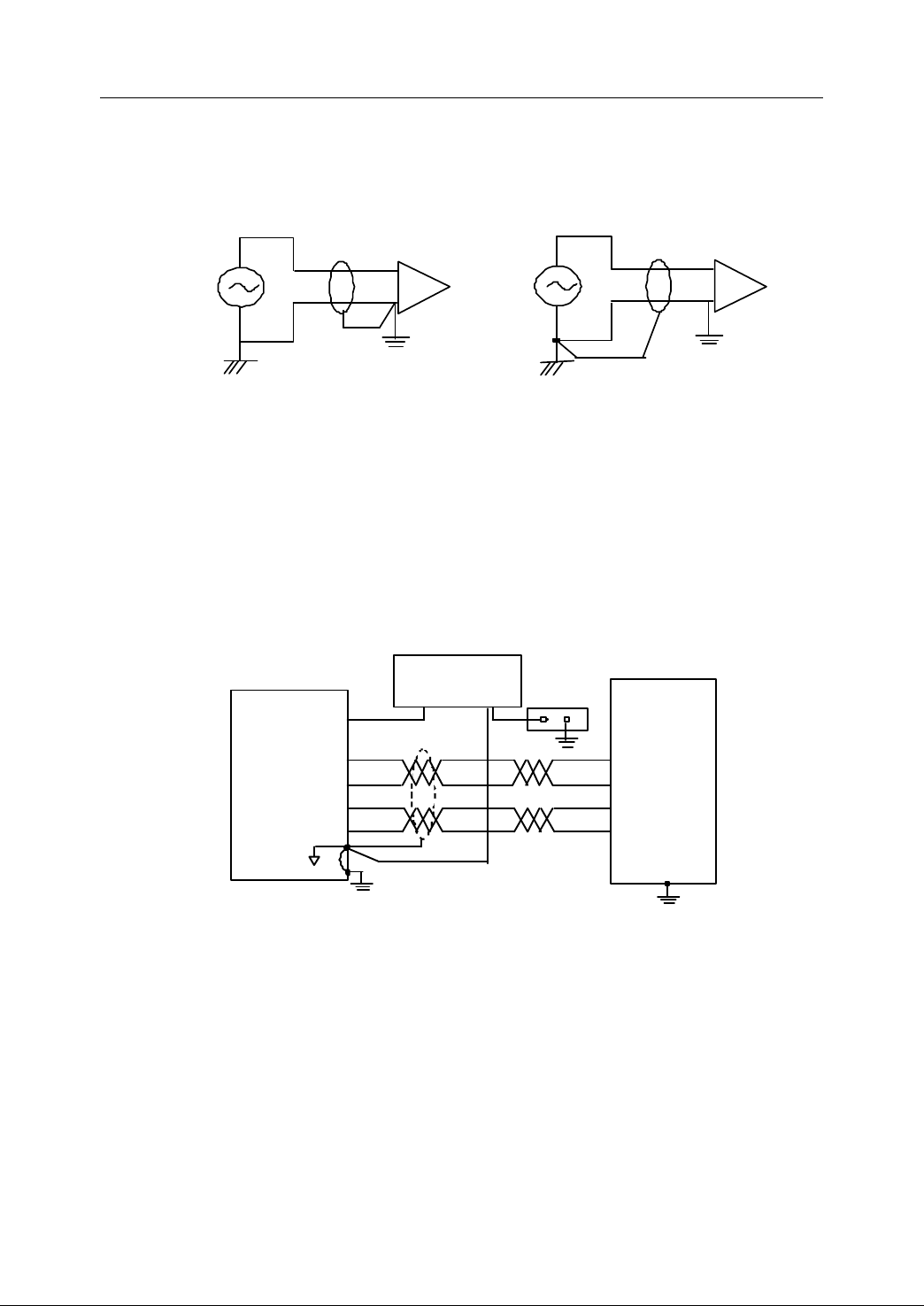
2. Connection
US
US
Step
per Motor
controller
( NC device )
24V DC
(+) (
- )
Step Motor
Drive
CP +
CP -
DIR+
DIR
-
a) For the l ow-frequency circuits (f<1MHz) , it is usually single- ended ground ing .
The shielded cables sh all be single- ended grounded . The single- ended
grounding plays the role of both active and passive shielding against
electrical fields. However, no shielding role against magnetic fields exists .
(a) grounding at input end (b) grounding at output end
Figure 2 64 Shield grounding for low-frequency circuits
b) Single-point grounding is used , when the cable length L<0.15 λ (where λ =c/f).
In the power supply or load circuits, no matter what single-core or
multiple-core shielded cable, is connected to the ground at one end, and the
other end is insulated from the ground. The grounding point is the shield
ground. The best way of grounding the shielded cables is the grounding at
output end without a loop. Grounding at the input end can also work .
Figure 2 65 Example of single-point shield grounding
c) For the h igh-frequency circuits (f>1MHz) , it usually uses the double-ended
ground ing. T he shield of shielded cables sh all be double-ended grounded.
Double-ended grounding plays the role of shielding against both electric
fields and high-frequency magnetic fields. The shield of shielded power
cables sh all also be double-ended grounded .
65
Page 76
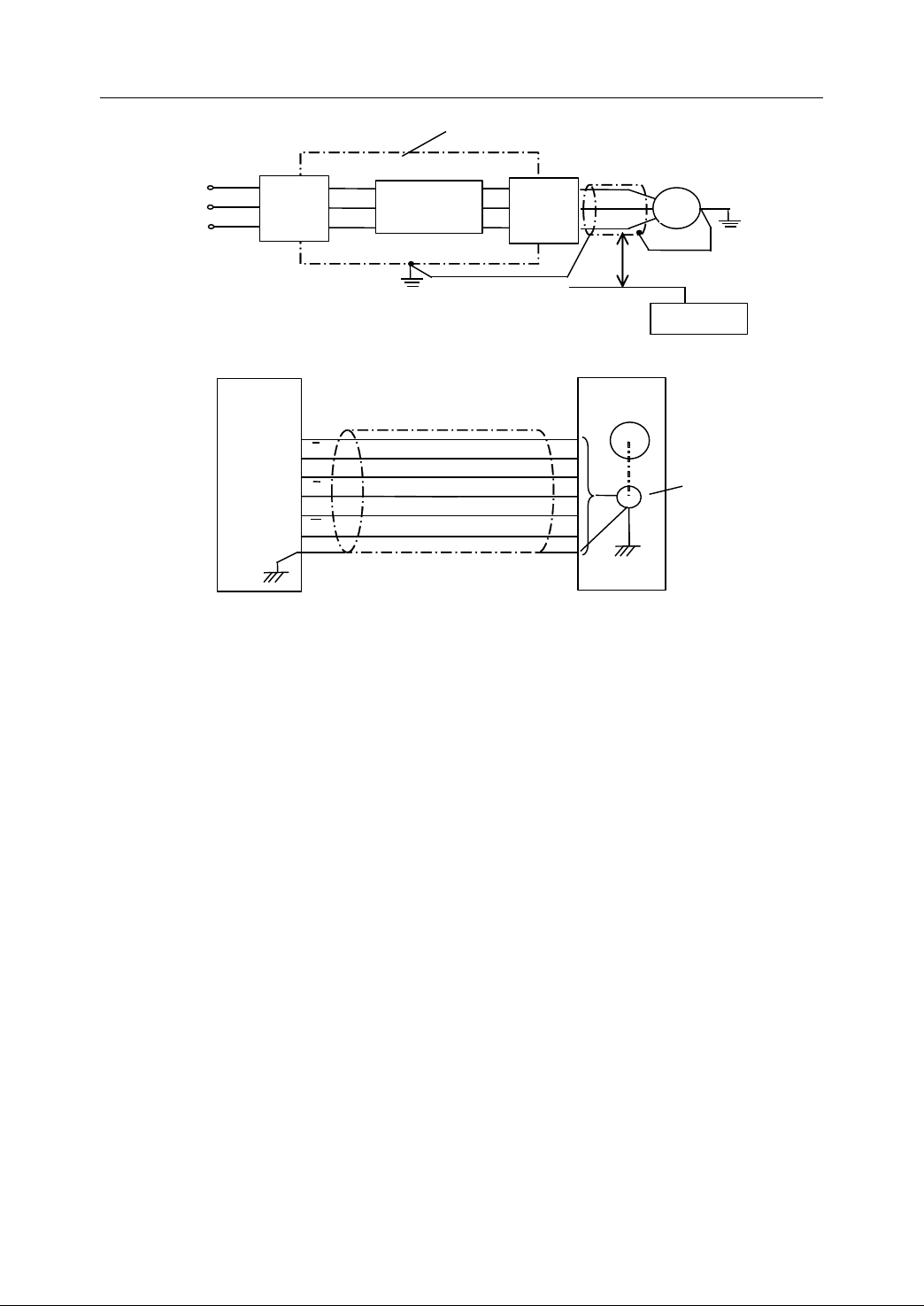
2. Connection
Metallic case
Noise
filter
Frequency
converter
Noise
filter
M
>30cm
Signal line
Controller
Figure 2 66 Double-ended grounding of shielded cable
Servo
d river
A
A
B
B
Z
Z
Servo
motor
S
Optical
encoder
Figure 2 67 Double-ended grounding for encoder cables
d) When the cable length L>0.15 λ ( λ =c/f), the multi-point grounding shall be
used. Grounding the cable shield at intervals of 0.05 λ or 0.1 λ is
recommended (at least to ground both ends of the shield) to decrease the
ground reluctance and reduce the interfere nce induced by ground potential .
e) It is recommended to use shielded twisted pair to transmit signals between
NC device and servo drivers or frequency converter. In this case,
double-ended grounding is used.
f) The shield of input signal cables sh all be grounded just where it enters the
device case . And the external interference signal is directly grounded to the
entrance of device case , rather than be grounded within the case to let it
rush into the device .
g) For the circuit with high input or output reluctance, especially in the
environment with the high static voltage, the double shielded cables can be
used. In this case, the in ternal shield is grounded at the source end, and the
external shield is grounded at the load end .
h) Avoid the so called “ pigtail ” effect w hile grounding the shield.
To
shield of multiple-core cables, the special metal clips are used .
66
ground the
Page 77

2. Connection
2.11.3
2.11.3
2.11.3
2.11.3 Check
A
good environment of power network is one of the key points to ensure safe and
reliable work to equipments. There are three measures commonly used to check the
network interference .
2.11.3.1
2.11.3.1
2.11.3.1
2.11.3.1 Supply
The supply filter can check the network interference from coming into the equipment .
It can also check the interference of equipment from pollut ing the network .
- Essentials of supply filter design
1) The filter is installed where AC supply lines enter the cabinet. Do not make
2) In case the supply lines must be connected to the filter through fuses and
3) It is better to fix and connect the metal case of the filter directly onto the
Check
Check
Check Interference
Supply
Supply
Supply Filter
the long distance of connection between AC supply lines and supply filter ,
which is to check the radiating interference from cabinet.
switches , the wires sh all be shielded .
Interference
Interference
Interference from
Filter
Filter
Filter
from
from
from Power
Power
Power
Power Network
Network
Network
Network
metal cabinet, being as close as possible to the ground point on the cabinet .
4) The input and output lines of the filter sh all be laid separately. Do not lay
them in parallel, especially not bundle up them together . Otherwise, the
interference from the input lines would be directly coupled to the output lines
without through the filter.
5) Use the double-twisted wires for the filter output wires t o strengthen the
anti-interference ability .
6) In case there is much high voltage pulse interference in the power network,
the filter having better attenuation in a broader frequency band or connecting
to the ferrite ring filter in series is recommended to obtain better filtering
effect .
7) The current through the filter sh all not be more than its maximum rating.
Otherwise , the inductance will decrease much and the filter will not effect,
because of the saturation in magnetic cores .
67
Page 78
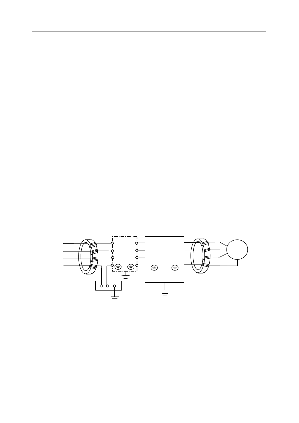
2. Connection
2.11.3.2
2.11.3.2
2.11.3.2
2.11.3.2 A
A
bsorbent
A
bsorbent
A bsorbent
bsorbent F
F
ilter
F
ilter
F ilter
ilter
Absorbent filter can check the inference of rapid transient pulse s series in the
transmission lines . It is made of the energy consumption component . The ferrite
absorbent filter is commonly used. It absorb s the interference energy in a given
frequency band and converts to heat loss to make the filtering effect .
- Essentials of interference filter made of ferrite rings design
1) The cables sh all be nestled closely to the inner wall of the ring (no large gap
is allowed) to concentrate the most possible magnetic flux within the ring
body . Thus, the filtering effect is improved.
2) Let both AC and DC supply lines pass through the ferrite rings to check the
interference of rapid transient pulse series .
3) Pass the wire s through the ferrite rings with the same direction and same
turns. The more the turns are , the better the filtering effect is . Generally, 4~5
turns are taken at the input side of power equipments (servo drivers or
frequency converters) . If the wires are quite thick, then more than two ferrite
rings can be used, the total turns is 4~5. However, the turns at output side
shall be less than 4.
5 turns 4 turns
L
1
L
2
L
3
PE
Ground bus
Figure 2 68 Filter circuit for servo driver or frequency converter
Note:
Note:
Note:
Note: In Figure 2-68, the s upply filter sh all be only put at the input side of
Supply filter
L
U
1
L
V
2
L
W
3
Servo driver
(Transducer)
M
servo driver (or frequency converter ), instead of its output side. The ground
wire can also not be turned through the ring. I n some cases , the ground wire
not passing through the ring makes the effect of filtering better.
68
Page 79
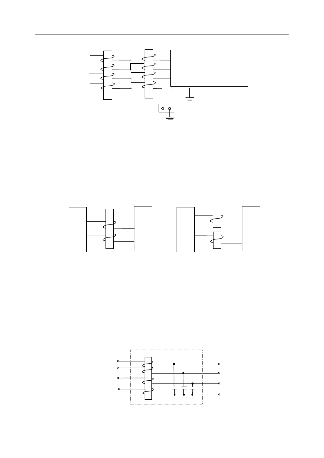
2. Connection
2 turns
L
1
L
2
L
3
P E
2 turns
Servo Driver
L
1
L
(Frequency converter )
2
L
3
Figure 2 69 Two magnetic rings connected in series
4) EMC filter, constructed by connecting the magnetic ring and the supply filter
in series, possesses better filtering effect .
5) While using the magnetic ring to check the common-mode interference in DC
supply and signal wires, it is better to pass either the positive and negative
lines or signals through the ring. Then, t he ring is not easy to be saturated .
Magnetic ring
Magnetic ring
+
+
+
-
DC supply
Device
-
-
DC supply
+
Device
-
(a) checking common-mode interference (b) checking difference -mode interference
Figure 2 70 Filtering circuit for DC supply
6) If the load reluctance using the magnetic ring or magnet ring is high, then the
magnetic ring will not be effective. The reason is that the reluctance of the
ring is only hundreds of ohm when the frequency is hundreds of mega - Hz.
Therefore, the ring is suitable for the circuits with low reluctance. Adding
capacitors in parallel after the ring to construct a filter similar to L-C type
would decrease the load reluctance much to improve the filtering effect .
L
1
L
2
L
3
Figure 2 71
A
typical circuit to check the transient pulse interference for AC supply
69
Page 80
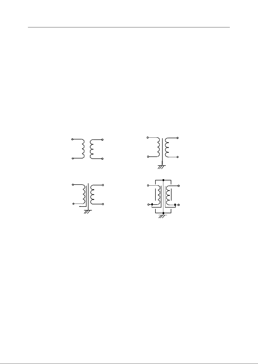
2. Connection
(a) simple isolation transformer
(b) isolation transformer with shield
(c) super (m ultilayer) isolation transfo rmer
Pri mary
Sec ondary
Sec ondary
case
Pri mary
Sec ondary
Sec ondary
Pri mary
Pri mary
2.11.3.3
2.11.3.3
2.11.3.3
2.11.3.3 I
I
solation
I
solation
I solation
solation
T
ransformer
T
ransformer
T
T
ransformer
ransformer
The isolation transformer, a commonly used device to check the interference from
supply, acts basically the role of implementing the electrical isolation between
circuits. It prevents equipments from being disturbed by currents flowing in ground
loops. It reduces the common-mode interference to a certain extent. It works well in
check ing the transient pulse series and the thunderstroke surge interferences
Generally, t here are three types of isolation transformers: simple isolation
transformer, isolation transformer with shield, and super (multilayer) isolation
transformer .
- Essentials of isolation transformer design
1) The isolation transformer with shield is widely used. The supper isolation
transformer is used only under special conditions .
2) Shield sh all be grounded directly and with short and thick connection wires.
Otherwise, it won ’ t work well in check ing the high frequency common-mode
interference .
3) Separate the primary and secondary wires of isolation transformer . Do not
lay them in parallel, especially not bundle up them together. It is better to use
double-twisted wire for the secondary output line to improve the ability of
anti-interference from magnetic fields .
70
Figure 2 72 Isolation Transformer
Page 81
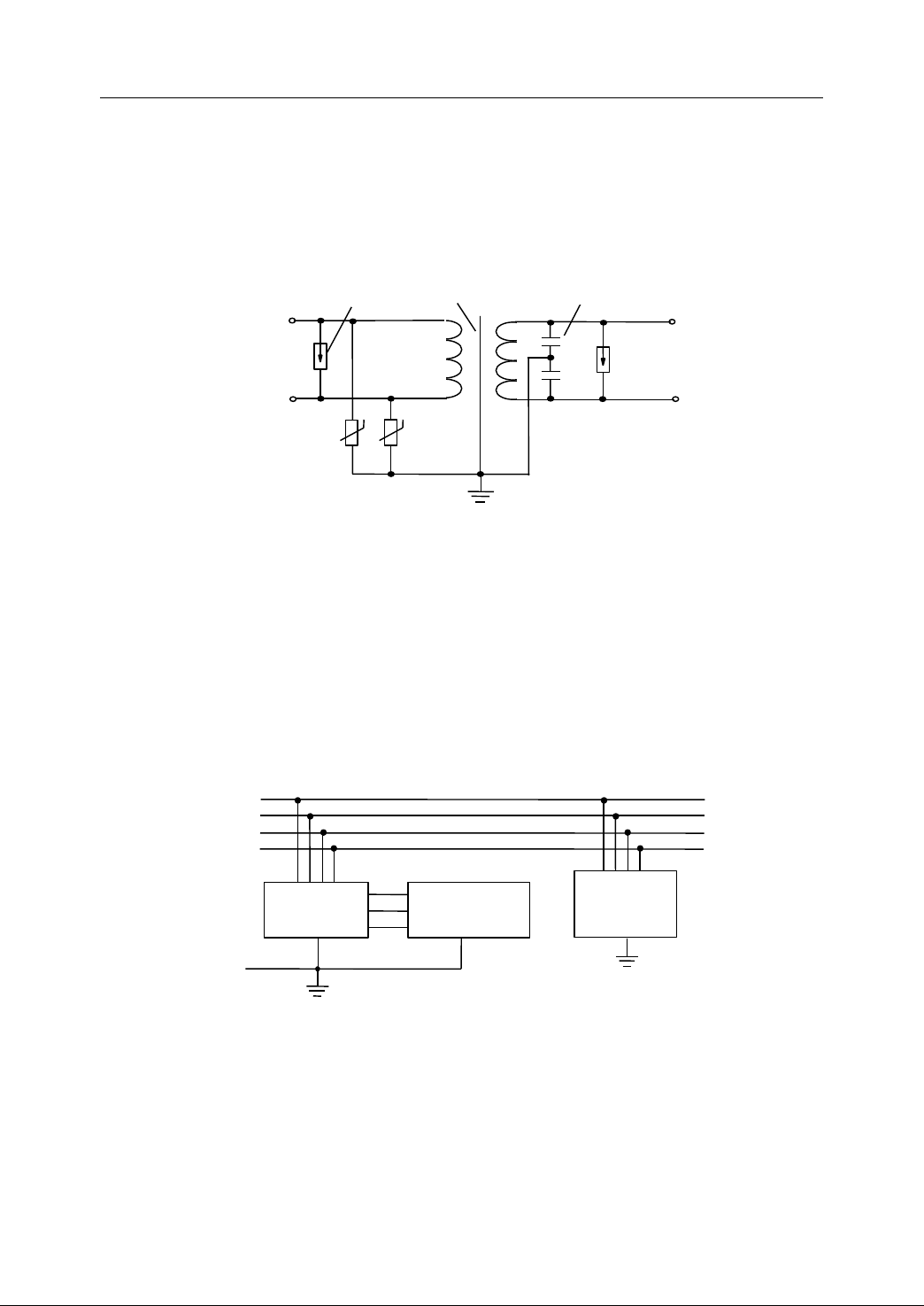
2. Connection
4) The isolation transformer works quite well in check ing the high-voltage pulse
surged by the thunderstroke. With an additional surge blocked device, the
AC supply transformer works as an anti-thunderstroke transformer .
5)
A
collocation of isolation transformer and magnetic rings checks effectively
the interference induced by high speed transient pulse series .
Lightening rod
Input
Surge absorber
Static shield
C
Output
Figure 2 73 Anti-thunderstroke T ransformer
In Fig ure 2 -73 , the lightening rod is a gas discharge tube . The surge absorber is a
voltage sensitive resistance. The transformer with shield and capacitance at its
secondary side can check the remaining common-mode interference in surging.
As for the under-voltage, overvoltage, and voltage undulation of the power network
during a quite long period, an AC voltage stabilizer shall be used to provide the
supply for NC device.
L1
L2
L3
N
AC
voltage
stabilizer
PE
Machine tool
NC system
Other
equipment
s s
Figure 2 74 AC Voltage Stabilizer
71
Page 82
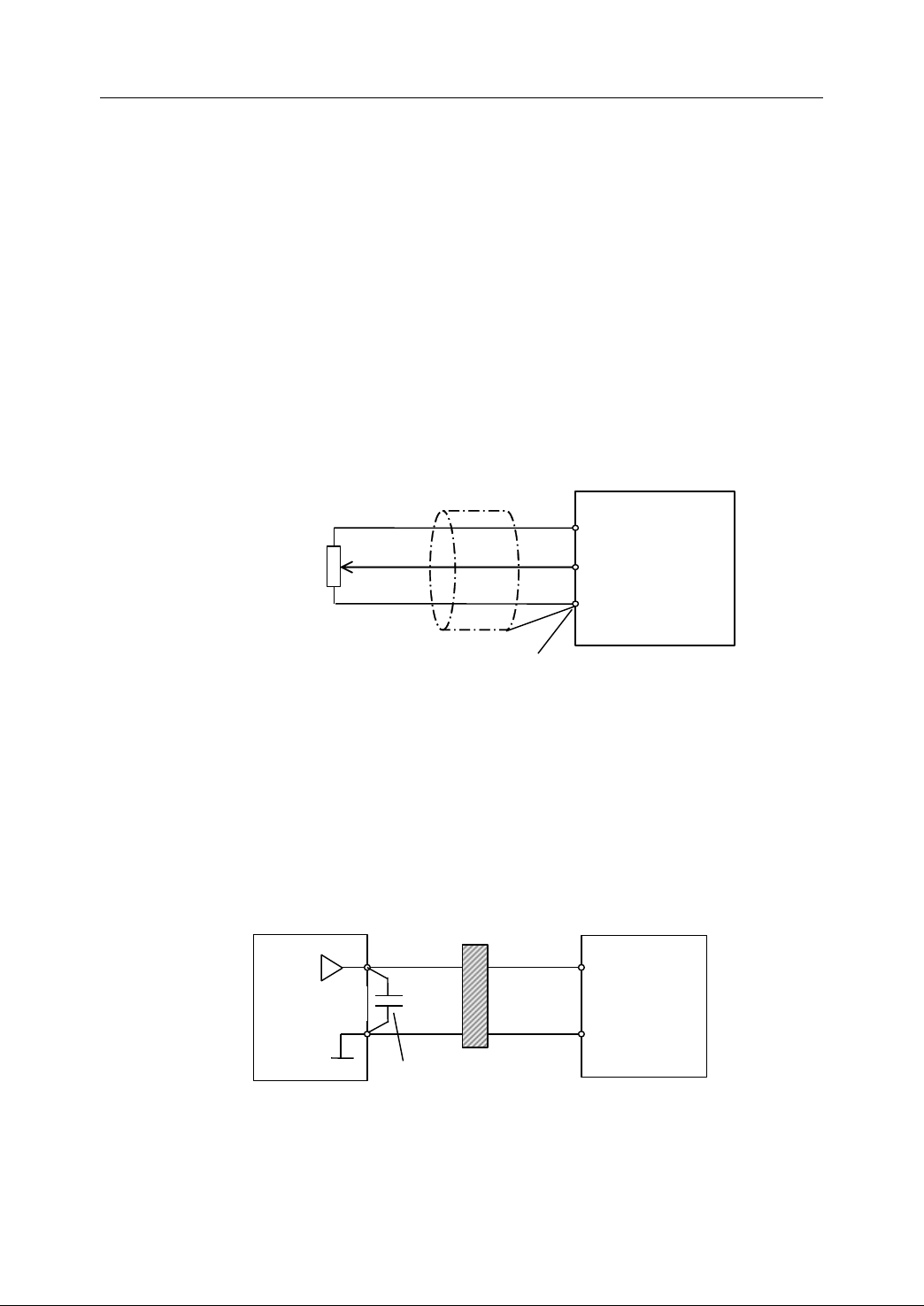
2. Connection
2.11.4
2.11.4
2.11.4
2.11.4 Anti-Interference
There are many ways to prevent signals from interference. Laying the power lines
and the signal wires separately, selecting proper grounding type, employing required
wires etc., are the common and effective ways to prevent signals from interference.
In addition, some methods depended on signal type may also be us ed. The ways to
check interference for both analogue and digital signals are introduced below .
2.11.4.1
2.11.4.1
2.11.4.1
2.11.4.1 Check
1. Because of being apt to be disturbed, the analog signal wires sh all have been
shielded and be laid as shortly as possible .
Anti-Interference
Anti-Interference
Anti-Interference
Check
Check
Check Interference
Speed
regulation
Interference
Interference
Interference in
in
Analog
in
Analog
in Analog
Analog Signals
Signals
Signals
Signals
Frequency
converter
(the common end of
analogue signals )
No connection to earth (floating potential)
Figure 2 75 Speed Regulation of Frequency converter
2. While servo drive or frequency converter is connected to the device with analog
output ( NC device ) , there would be a wrong action caused by the interference
from the device with analog output, the servo drive, or frequency converter. In
this case, the capacitors with ferrite rings can be connected to the device with
external analog output signal to check the interference .
Passing or winding 2-3 turns in the same direction
Servo driver
NC device
Figure 2 76 F iltering circuit for analogue signal wires
3. R-C lowpass is used to the analog signal s with slow variation.
C
0.022uf/50v
Ferrite ring
( Frequency
converter)
72
Page 83
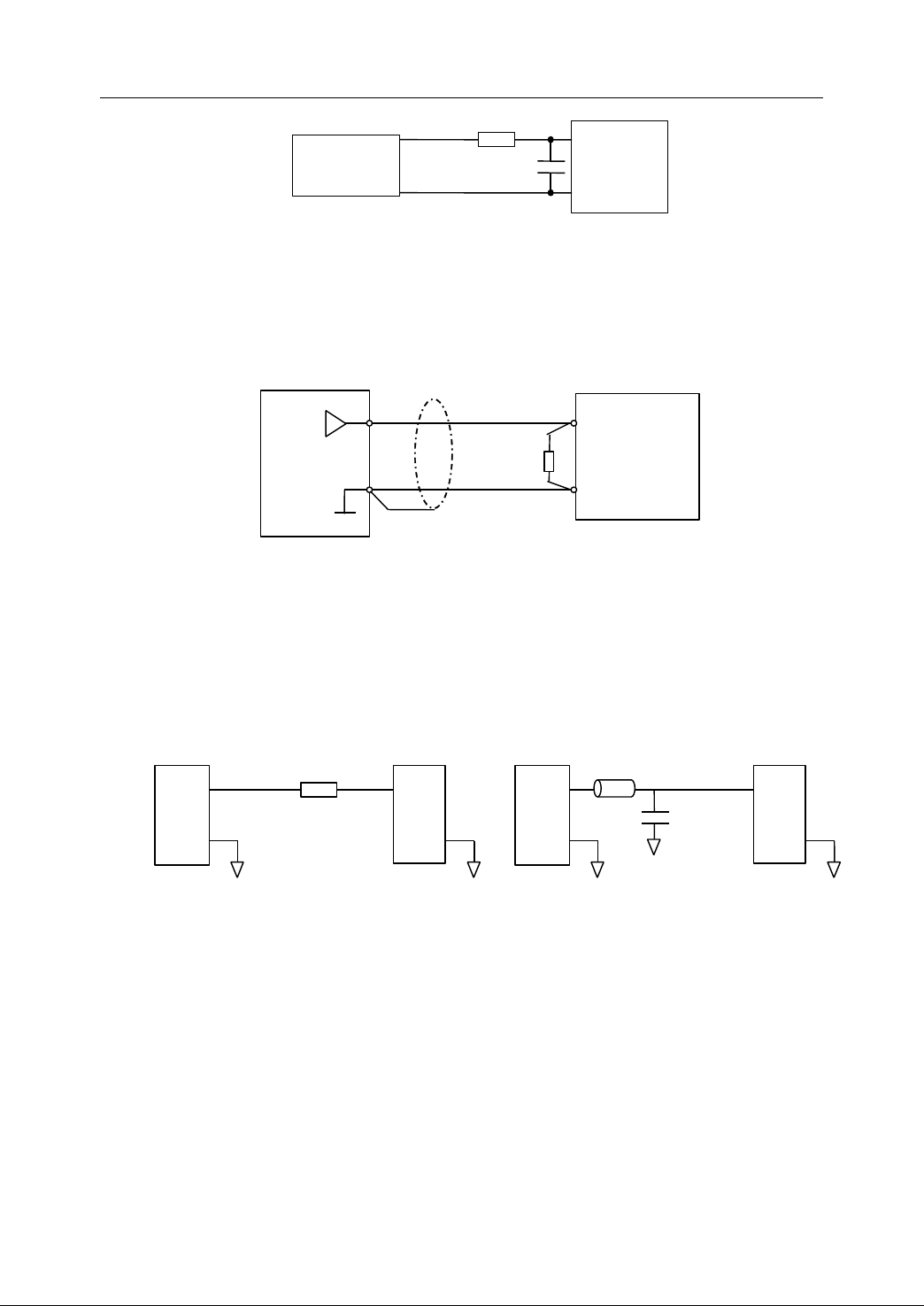
2. Connection
R
Transducer
Figure 2 77 RC Lowpass
4. Use the current transmission line instead of the voltage transmission line . Then,
the current is converted to voltage signal again by t he parallel resistance at the
end of long transmission wires. In this case, the wires sh all be shielded and
single-end grounded .
D/A
Interference
Interference
Interference in
in
in
in Digital
2.11.4.2
2.11.4.2
2.11.4.2
2.11.4.2 Check
1.
A
resistance connected in series or a lowpass filter can be used to check the
Check
Check
Check Interference
NC
device
Figure 2 78 C urrent T ransmission of Analogue S ignal
C
R
Digital
Digital
Digital Signals
Amplifier
Servo driver
Transducer
Signals
Signals
Signals
o r
wave oscillation of digital signals caused by the improper cabling and a large
loop of signal wires.
R
Circuit 1
(a) Inserting a damping resistance in series
Figure 2 79 Checking the digital signal oscillation
2. H igh frequency decoupling capacitors should be set at the connector ends of
i nput/output transmission wires. Generally, the frequency of I/O signals is lower
than the clock
connected between I/O and the ground should ensure that I/O signals can work
normally and filter high clock frequency and its harmonics . C apacitance should
be connected between I/O wires and the ground wires.
3.
A
data circuit filter equipped at signal wires can check the high frequency
’
s . The selection of a high frequency decoupling capacitance
Circuit 2
Circuit 1
(b) Inserting a lowpass filter
Bead
C
Circuit 2
73
Page 84
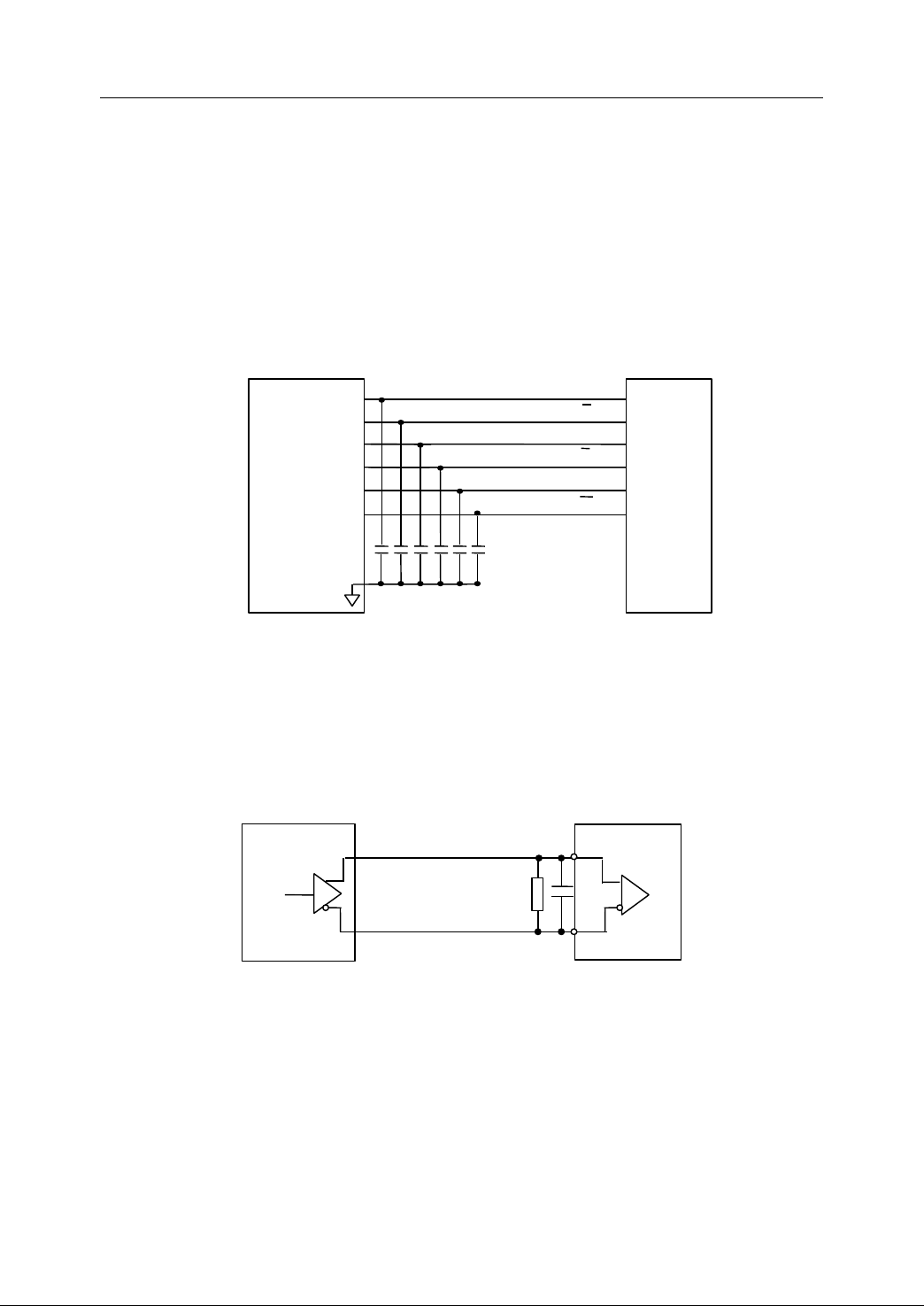
2. Connection
common-mode interference effectively. The filter is compose d of ferrite rings or
hollow capacitors . For example, the cable can be equipped a ferrite ring near
the transformer . The best way is to use a connector with filter. E ach socket of
this kind of connector contains a filter composed of a ferrite bead and hollow
capacitor .
4. The output signals coming from the optical encoder, electronic hand-wheel, and
raster ruler etc at the receiving end are connected to the capacitances in parallel,
which can check the interference with high frequency.
A
Position
loop board
(NC device)
A
B
B
Z
Z
Optical
encoder
output
0V
Figure 2 80 C onnect ion with c apacitance in parallel
5. R educe the input reluctance of sensitive circuits.
6 × C (ceramic)
C : 1nf~0.1uF
A
capacit ance or a resist ance
with low ohm is connected in parallel to the input side of a CMOS circuit , which
can reduce the static electricity interference . For the differential transmission of
digital signal, a capacit ance and a resist ance are connected in parallel to the
input side of digital signals , which can improve the anti-interference ability .
NC device
R
C
T
T
R
51~200 Ω
T
:
C
47~220PF
T
:
Figure 2 81 Reducing I nput R eluctance
2.11.5
2.11.5
2.11.5
2.11.5 Prevention
Prevention
Prevention
Prevention of
of
Producing
of
Producing
of Producing
Producing Interference
Interference
Interference
Interference
Besides checking the interference coming from outside, it also needs to take proper
measures to reduce the interference from NC unit. Shielding and the absorbent
circuit for inductive load are recommended .
74
Page 85

2. Connection
2.11.5.1
2.11.5.1
2.11.5.1
2.11.5.1 Shielding
Shielding is the most effective and frequently adopted method . The shield technique
has been applied to check the electromagnetic interference propagated in the air, i.e.
to cut off the route the interference moves along. Generally, use the metallic or
magnetic material t o separate the in ternal and external field of the shielded body
from each other .
Shielding is in principle divided into electrical field shielding, magnetic field shielding,
and electromagnetic field shielding .
1. Electrical field shield ing
If the interference is from the high-voltage and low-current, its radiation field is
mainly electrical. The electrical field shielding is to check the interference
induced by the electrical field coupling between the interference source and the
sensitive equipment s.
Shielding
Shielding
Shielding
Note:
Note:
Note:
Note: Good g rounding is the prerequisite for the metallic plate producing
electrical field shielding . No grounding or bad grounding may result in even more
serious interference than that of the situation with out the metallic plate equipped .
- Essentials of Electrical field shielding design
a. Ground ing firmly with the metallic outer cases of power equipments (such as
servo drivers, frequency converters , step per drivers, switching supply ,
motors) is to construct active shielding .
b. Grounding firmly with the outer cases of sensitive equipments ( such as NC
devices etc.) is to construct passive shielding .
c. Keep the power equipments far away from the sensitive equipments.
Generally, the equipment with strong current should be more than 30cm (at
least 10cm) far away from the equipment with light current in the same
cabinet .
d. Keep the power wire s with high-voltage and large-current separate from the
signal wire s . For example, use the independent slot, and keep more than
75
Page 86

2. Connection
30cm (at least 5~7.5cm) far away. Try to avoid laying the wires in parallel.
Do
not
tie
Do
not
Do
Do not
not tie
those
tie
those
tie those
those two
two
kinds
two
kinds
two kinds
kinds of
of
wires
of
wires
of wires
wires up
up
up
up .
.
.
.
e. Lay the signal wires as close as possible to the ground wires (or ground
plate) , or use the ground wires to surround them .
f. The prerequisite for the shielded cables providing the passive and active
M
ore
shield is that the shielding is grounded. M
M
M ore
electrical
ore
electrical
ore electrical
electrical field
field
field
field coupling
coupling
coupling
coupling
would
would
would
would be
be
produced
be
produced
be produced
produced ,
,
if
the
,
if
the
, if
if the
the shielding
shielding
shielding
shielding is
is
not
is
is not
grounded
not
grounded
not grounded
grounded .
g. I f the power wires cannot be laid separately from the signal wires, the power
wires sh all be shielded and grounded reliably .
2. Magnetic field shieldi ng
If the interference source is with low-voltage and large-current, its radiation is
mainly of magnetic field. The magnetic field shielding is to check the interference
induced by the magnetic coupling between the interference source and t he
sensitive equipment. It is characterized as the low magnetic resistance of the
material with high magnetic conductibility, which can bypass the flux and reduc e
the strength of magnetic field in the shield a lot .
- Essentials of Magnetic field shielding design
a. Use the material with high magnetic conductibility, such as permalloy, and
increase the thickness of shield properly .
b. Do not set the shielded items near the shied . Try t o reduce the flux flowing
through the shielded objects,
c. Pay attention to the structure design of shield. For shield a stronger field, the
double-layer magnetic shielding can be employed .
d. Reduce the loop area of the interference source and the sensitive circuit. The
best way is to use the twisted wires or the shielded wires and make the
signal wire and the ground wire (or carr ier loop) twist ed together, which
mak es the shortest distance between them .
e. Increase the distance between the interference source and the induced
circuits to make their mutual inductance as less as possible .
f. If possible, l ay the circuit of the interference source perpendicular (or
76
Page 87

2. Connection
approximately) to the induced circuit , which gr eatly reduce s the magnetic
coupling between them .
g. K eep the sensitive equipments at least 30cm away from the interference
source (such as power equipments, transformers) .
3. Electromagnetic field shieldin g
Electromagnetic field shielding is to check the interference from the
electromagnetic field coupling when the interference source is far away from the
sensitive equipment. It must shield both the electrical and the magnetic fields.
The materials with l ow resistance and good conductibility are usually used . The
electromagnetic waves are reflected and absorbed when they are reached the
metallic surfaces. The electromagnetic energy is then reduced a lot, so that the
shielding takes effect .
- Essentials of shielding box design
A. Structural Material
a) Plates made of copper, iron, aluminum or zinc-coated iron with the
thickness around 0.2~0.8 mm is generally taken as the shielding materials.
These plates shield the electrical field, the high frequency magnetic field,
and the electromagnetic fi eld effectively (over 100dB) .
b) The ferromagnetic material with high-conductibility is not used to make a
case, but on the components requiring the low-frequency magnetic
shielding.
c) For the plastic case, spray its inner surface with a conducting layer, or add
the metallic powder or fiber with high-conductivity during molding to make a
plastic case conductive.
B. Overlap joint
The electrical continuity of cases is the critical factor of shielding
effectiveness of the shell . Thus, decreasing the electrical dis continuity of
the shell is to limit the electromagnetic field leakage and radiation from the
base plate and cabinet.
77
Page 88

2. Connection
a) Make the best overlap joint at any gaps and dis continuity area of chassis
and c abinet.
b) Ensure that the corresponding metallic contacts are connected firmly at any
gap of joint to prevent from the leak age and radiati on of electromagnetic
field .
c) Weld the gaps of joints if possible . I n the limited condition, dot welding, close
riveting, or s c rew fixing is used .
d) Any fix ture sh all be strong enough to keep surfaces contact to each other
under stress, shock, and vibration .
e) The material made of c onductive liner o r finger setting bolt spring sh all be
used at any uneven gap of joint or the removable panel .
f) Be sure there is no insulated protective layer (such as paint, plastic film) on
the metallic surface where the liner is used .
g) When the moving contact is required, u se finger setting bolt spring , rather
than grid liner, and keep the pressure of the finger setting bolt spring .
Note:
Note:
Note:
Note: There are some kinds of liners , such as radiofrequency metallic grid liner,
copper-coated alloy liner, conductive rubber liner, conductive covering cloth liner,
and foamed liner .
C. Inlets and Outlets
Generally, there are lead-in and lead-out of the supply lines and contro l
wires in the chassis . There are also some operational keys on the panel,
the interface for screen, vent etc. All of these ma y lead to serious leakage of
electromagnetic waves .
a) Pay attention to the reduction degree of t he whole shielding effect , when the
cables are through the case .
A
typical unshielded cable decreases more
than 30dB of shielding effect , when it is p assing through a shielded body .
b) All the supply lines sh all pass through filter boxes while entering into the
case .
c) Any signal or control wire s sh all pass through a proper filter while coming
in to or going out of the case .
78
Page 89

2. Connection
d) A dd metallic caps on fuses and sockets etc.
e) Use conductive liners , washers and nuts to prevent the leakage of toggle
switches .
f) The cellular plate is used to shield the vent where the shielding, ventilation,
and strength are strongly required and the weight is not limited harshly. It is
better to weld the cellular plate firmly to prevent the electromagnetic
leakage .
g) It is better to shield indicators/screens in the rear, and filter all the lead -wire s
with the hollow capacitors. If it is hard to implement those measures , use the
metallic net or the conductive glass connected to the case to shield in front
of these indicators or screens ( t he shield glass embedded with metallic
thread, or the glass or clear plastic coated with clear conductive film is
recommended .).
2.11.5.2
2.11.5.2
2.11.5.2
2.11.5.2 A
While being turned off, the inductive loads, such as relays, contactors,
electromagnetic valves, and motors, would produce intensive pulse interferences
and hinder other circuits from working normally. A n absorber circuit is required to
check the transient interference. Figure 2-82 shows the schematic diagrams of the
absorber circuits .
Note:
Note:
Note:
Note: According t o different requirements , the ends of inductive load can be
connected in parallel to the absorber circuits, such as resist ance , voltage-sensitive
resist ance , voltage reference diode, etc. However, R - C ( arc extinguisher) circuit is
recommended because of its good absorbe nt effect. The extinguisher should be
installed as close as possible to the inductive load .
A
bsorbe
A
bsorbe
A bsorbe
bsorbe r
r
C
r
C
r C
C ircuit
ircuit
ircuit
ircuit for
for
for
for I
I
nductive
I
nductive
I nductive
nductive L
L
L
L oad
oad
oad
oad
79
Page 90
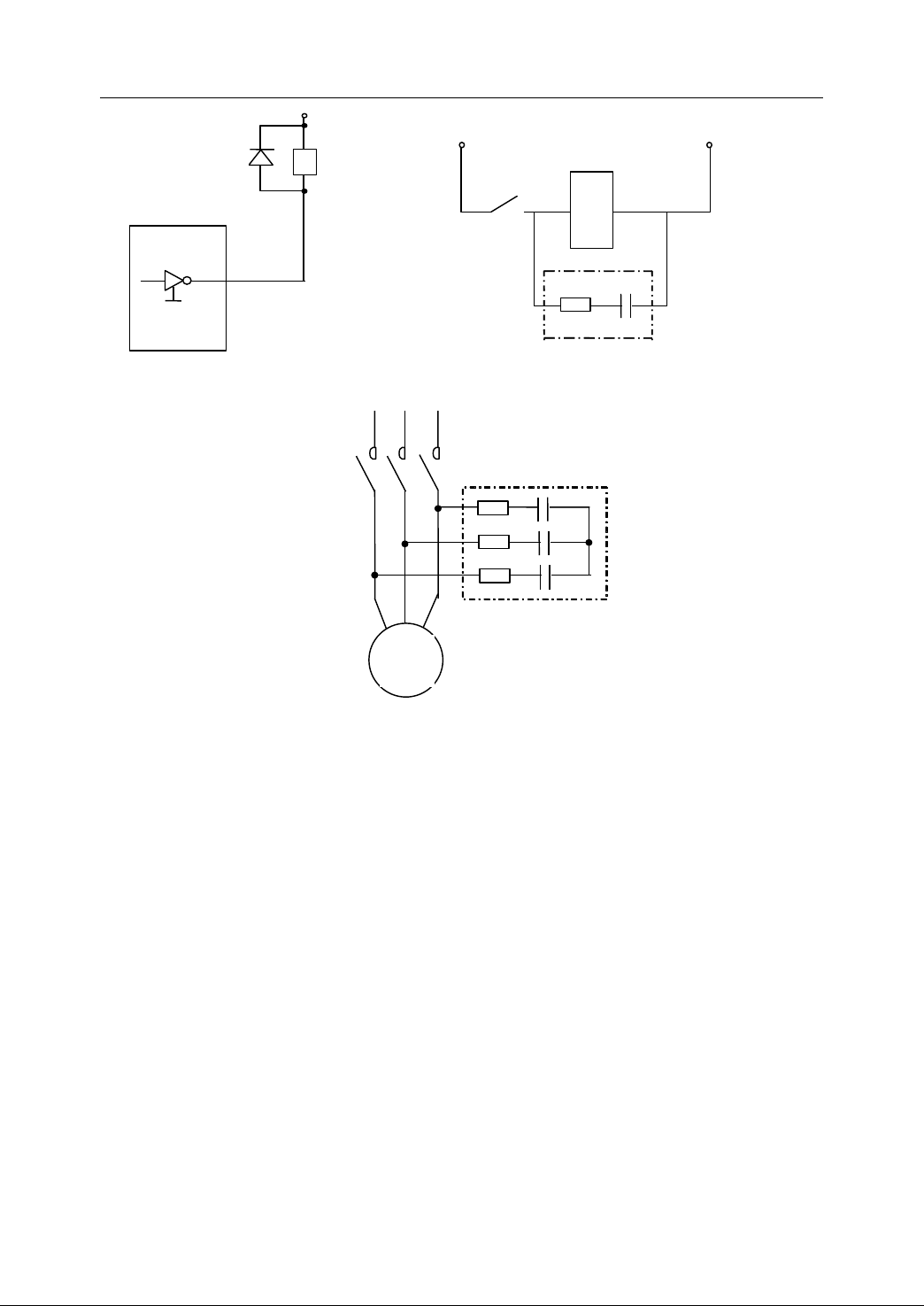
2. Connection
+24V
IN4001
MC1413
Output
Interface
(a) The shunt diode for DC relay coil
J
KM
KM
J
R
50 Ω ~1 K
(
C
R
(b) The shunt R - C (arc extinguisher) for coils of
AC relay, contactor, and electromagnetic valve .
Arc Extinguisher
M
3~
C ( 0.1uf~2uf )
Arc Extinguisher
)
( c ) T he arc extinguisher for AC three-phase AC induction motor
Figure 2 82 Absorber components for inductive loads
2.11.6
2.11.6
2.11.6
2.11.6 Summary
- The control cabinet must be made of cold-rolled steel plates.
Summary
Summary
Summary of
of
Design
of
Design
of Design
Design Guide
Guide
Guide
Guide
To
keep the
electromagnetic consistency of cabinet, the single-body structure or welding is
recommended .
- The cabinet is made of zinc-coated steel plate to improve the grounding effect of
the system .
- In cabinet, each component is installed and laid separately according to the
power level (strong or light).
- The shield layer of all the shielded cables sh all be grounded at their entrance
into the cabinet .
- The power wires and feedback wires of every feed drive motor or spindle motor
with drive sh all be connected to the drive unit directly, not through the terminals .
80
Page 91

2. Connection
- Use the shielded cables for the signal wires with the light current , such as the
position feedback wires, the command given wires, and the communication
wires. The cross section area of every single lead sh all not be less than 0.2 mm
It is better to use t he double-twisted, double-shielded cable s.
- The twisted multiple core wire s are recommended for the power supply cables in
the shielded cables of I/O terminal boards and encoder feedback, to raise the
anti-interference ability of signal supply and relevant components .
- The case of each component must be grounded reliably .
-
A
reliable common ground is required among component s .
Fig ure 2 -83 shows a n example of comprehensive electromagnetic compatibility
design for a system including NC device, driver, AC induction motor, contactors and
valves. The logic control components (such as air switches, contactors, relays) and
their circuits are omitted .
2
.
81
Page 92
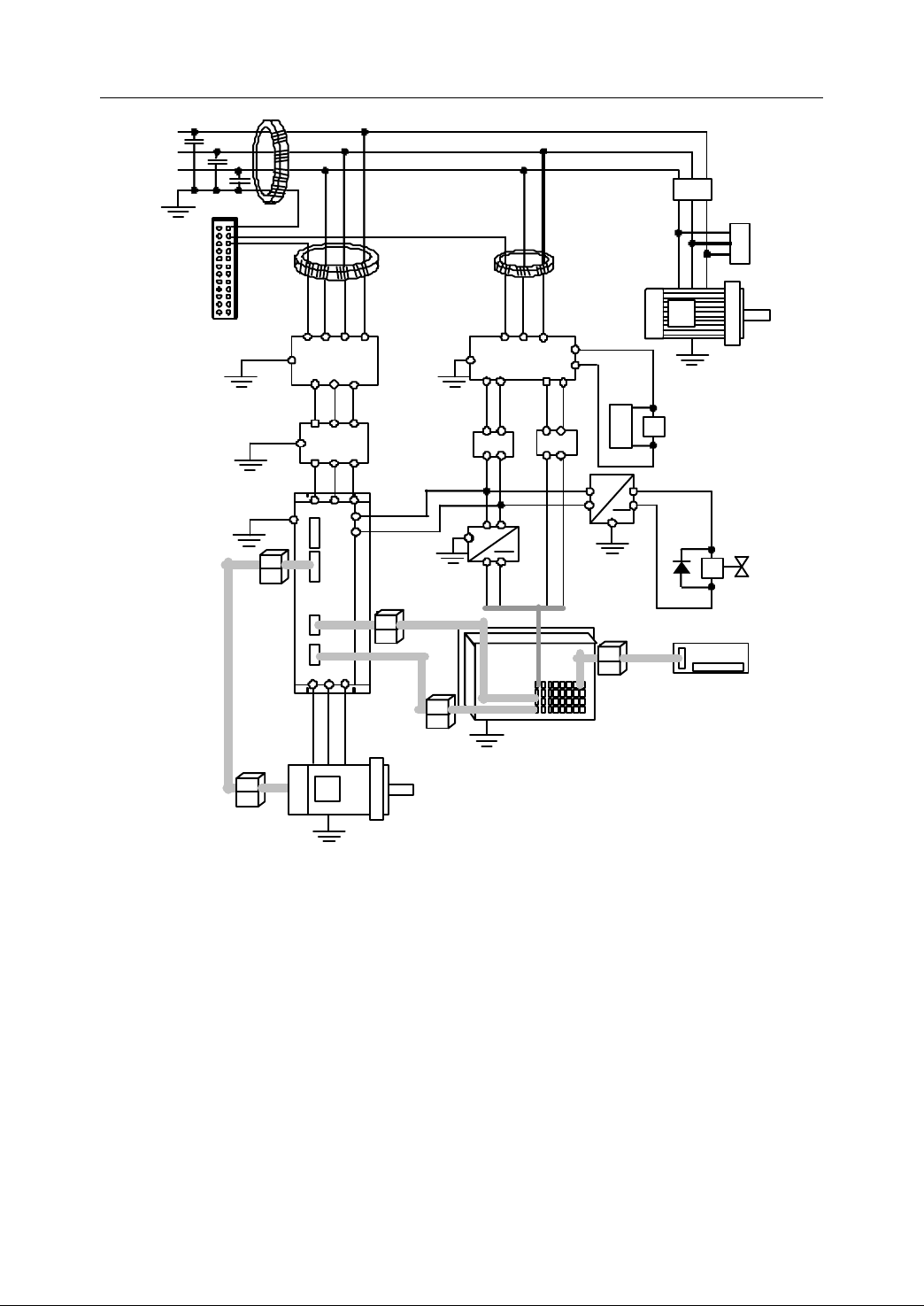
2. Connection
HNC-21 /22
G
rounding bar
Isolation transformer
L ow - pass
~
L1
L2
L3
PE
*1
*4 *3
*3
*
2
* 6
*
5
* 3
* 6
* 7
*7
Low -
pass
* 8
* 8 *5
KM1
KM1
* 7 *7
* 9
*7
* 7 *10
*
10
*10
D rive unit
I/O
terminal
board
* 7
* 7
*11
*
11
* 11
* 11
*10
Co mmand
feedback
Power
feedback
C
ontrol
power
D rive power
Supply for
contactors
DC24V
AC24V
Asynch.
motor
D rive motor
*
5
YV
~
* 9
* 7
+ -
valve
DC v alve supply
Note:
1. T he system should be connected reliably to ground and PE ground b ar in the
2. Grounding with the high-voltage (2000V) ceramic capacitances at the entrance
3. Wind the wire through the magnetic ring 4-5 turns .
82
Figure 2 83 C omprehensive electromagnetic compatibility design
control cabinet as close as possible . The grounding resistance must be less
than 4 ohm.
of power wires to cabinet (before the main air switch) with 3 phases reduces the
interference (pulse, surge) propagated along the supply cable obviously .
Page 93

2. Connection
4. The ground ing bar is made of copper plate not less than 3mm high. Good
contact and perfect conductibility are required .
5. RC extinguisher is us ed for large inductance loads (AC contactor coils, 3-phase
AC induction motors, AC electromagnetic value coils, etc.) to absorb
high-voltage back electromagnetic force and to check the interference .
6. Isolation transformers are used for servo supply, control supply and supply for
NC systems .
7. The shell of components and their shield sh all be grounded reliably. The ground
wires of some important components and the ground wires among the control
cabinet s sh all not be less than 2 .5 mm
2
.
8. Some important components, such as AC supply for NC system, sh all work with
low-pass filters to reduce the high-frequency interference from industrial
frequency supply .
9. If the power of NC unit is DC24V, the power supply can be shared with I/O
switches . The switching supply is suggested . However, an independent source
is requir ed to supply DC coils of valves and brakes .
10. Adding hollow ferrite cores at both ends of shielded cables, especially for the
position feed back cables and the command given cables, can effectively raise
the reliability of signal transmission .
11.
The shield layer of shielded cables must be thick and dense, with out gap or
crevice. Each wire must be multiple-core, no t less than 0.2 mm
2
. Several wires
connected in paralle l are used for the signal power cables (generally, supply
wire and supply ground wire use their own three wires connected in parallel ,
respectively.). It is better to use double-twisted and double-shielded cables .
83
Page 94

HNC- 21/22 Connection Manual
3
Parameters
3
Parameters
3
3 Parameters
Parameters
This chapter mainly describes the settings of parameters on HNC-21/22.
- Overview
- Setting Parameters
- Description of Parameters
84
Page 95
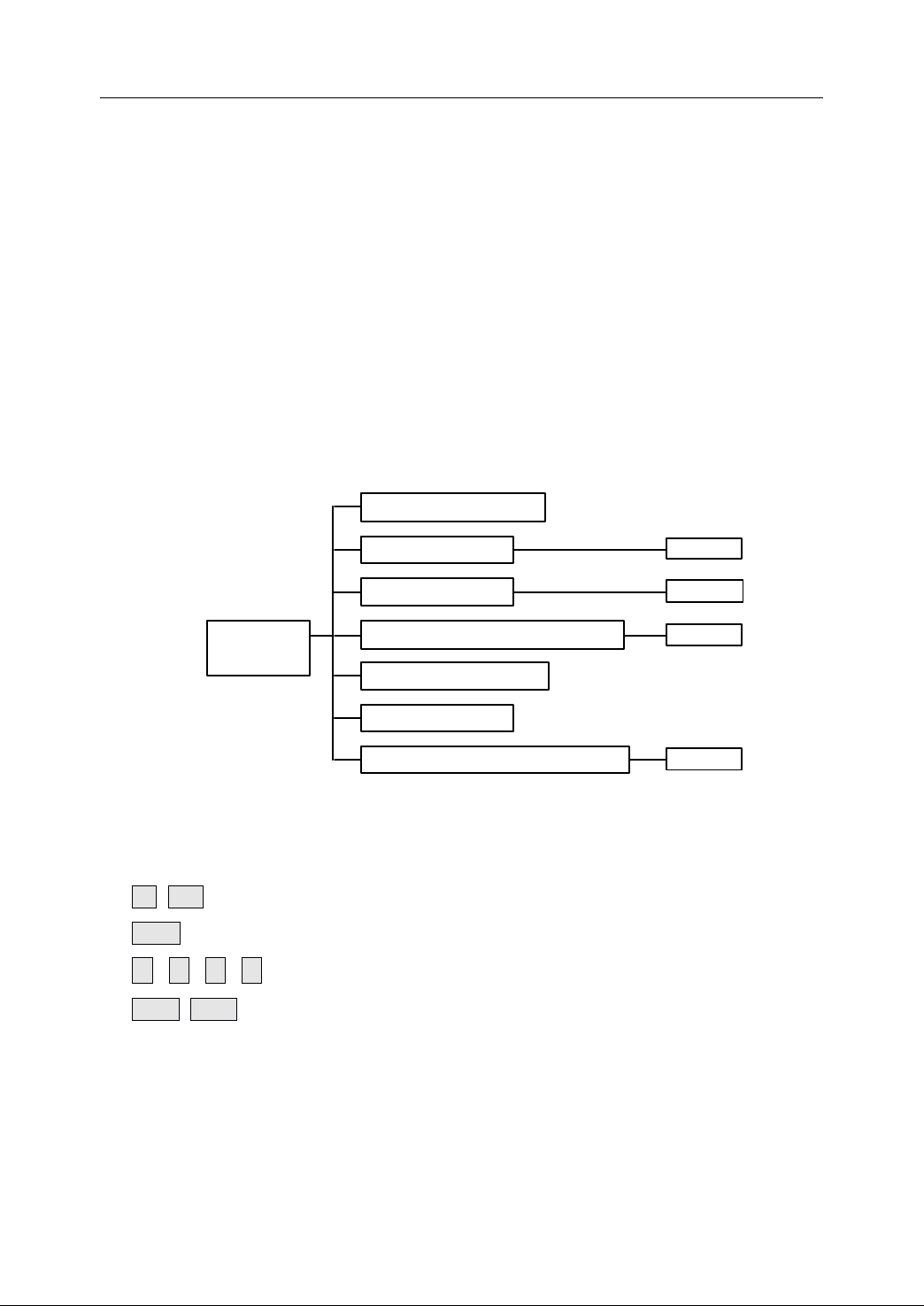
3.1
Axis 0~5
M achine parameter
A xis parameter
Servo parameter
Axis compensation parameter
PMC
user parameter
DNC
parame ter
Q uadrant transition parameters
Parameter
index
Axis 0~5
Axis 0~5
Axis 0~5
Overview
3.1
Overview
3.1
3.1 Overview
Overview
3. Parameters
Before
Before
Before
Before parameter
understood,
understood,
understood,
understood, as
result
result
result
result .
The
The
The
The modified
Thus,
Thus,
Thus,
Thus, NC
Description of common terminology and buttons:
1. T he index of parameters is shown in Figure 3-1.
parameter
parameter
parameter updating,
as
as
as incorrect
.
.
.
modified
modified
modified parameters
NC
device
NC
device
NC device
device shall
updating,
updating,
updating, its
incorrect
incorrect
incorrect parameter
parameters
parameters
parameters would
shall
shall
shall be
its
function
its
function
its function
function and
parameter
parameter
parameter setting
would
would
would be
be
restarted
be
restarted
be restarted
restarted once
and
and
and original
setting
setting
setting or
be
effective
be
effective
be effective
effective only
once
the
once
the
once the
the parameter
or
or
or updating
parameter
parameter
parameter s
original
original
original setting
updating
updating
updating may
only
only
only if
setting
setting
setting sh
may
may
may cause
if
NC
if
NC
if NC
NC device
s
are
s
are
s are
are modified.
sh
sh
sh all
cause
cause
cause the
device
device
device is
modified.
modified.
modified.
all
be
all
all be
is
clearly
be
clearly
be clearly
clearly
the
serious
the
serious
the serious
serious
restarted.
is
restarted.
is restarted.
restarted.
2. Screen: An area to display and modify the parameter values .
3. Buttons:
F1 ~ F10 : press one of these keys to implement the specific operation.
Enter : It is to confirm the operation.
,
,
↑
↓
Pgup , Pgdn : Press this key to move up /down one page .
,
←
→
Figure 3 1 Index of Parameters
: It is to move the cursor.
85
Page 96

3. Parameters
3.2
Setting
3.2
Setting
3.2
3.2 Setting
Setting Parameters
To
edit a certain parameter, the operator must input the correct password first. Those
parameters are divided into three groups: CNC vendor, Machine tool’s vendor and
the operator. Users from different group have different password. If the password is
wrong or the privilege is low, then the parameter is not allowed to modify. For more
detailed information, please refer to HNC-21/22 operation manual.
Parameters
Parameters
Parameters
86
Page 97

3.3
Description
3.3
Description
3.3
3.3 Description
Description of
of
Parameters
of
Parameters
of Parameters
Parameters
3. Parameters
3.3.1
3.3.1
3.3.1
3.3.1 Machine
Spindle encoder RPM [CNC manufacturer]
Turret direction [Operator]
D iameter/Radius [Operator]
Machine
Machine
Machine Parameters
Value : -32768~32767. The default value is 1024 .
Description : The number of pulse per revolution of spindle s ending from
Value : 0, 1 . The default value is 0.
Description : 0: the positive direction of axis X is downward.
Value : 0, 1 . The default value is 1.
Description : diameter/radius programming
Parameters
Parameters
Parameters
the encoder to NC unit.
1: the positive direction of axis X is upward.
0: radius programming
1: d iameter programming
Metric/Inches [Operator]
Value : 0, 1 . The default value is 1.
Description : measurement unit
0: unit of dimension is thousandth of an inch
1: unit of dimension is thousandth of a mini-meter
Power-off protection [Operator]
Value : 0, 1 . The default value is 1.
Description : 0: Power-off protection is disabled.
1: Power-off protection is enabled.
87
Page 98

3. Parameters
Decimal number for inches [Operator] (only used i n HNC-21/22 v7.11)
Value : 0, 1 .
Milling: the default value is 0.
Turning: the default value is 1.
Description : 0: the number of digits is four in inch measurement.
1: the number of digits is five in inch measurement.
Storage device [Operator] (only used in HNC-21/22 v7.11)
Value : 0, 1 . The default value is 1.
Description : 0: Floppy disk, 1: USB
System time [Operator]
Value : 0, 1 . The default value is 0.
Description : 0: enabled, 1: disabled
PMC axis [Operator]
Value : 0, 1 . The default value is 0.
Description : 0: disabled, 1: enabled
Spindle encoder direction [Operator]
Value : 32, 33. The default value is 32.
Description : 32: +; 33: -.
Tool
offset type [Operator] (not used in HNC-21/22 v7.11)
Value : 0, 1 . The default value is 0.
Description : 0: the type of tool offset is absolute .
1: the type of tool offset is incremental .
Tool
wear -off accumulation [Operator] (not used in HNC-21/22 v7.11)
Value : 0, 1 . The default value is 0.
Description : 0: no, 1: yes
88
Page 99

3. Parameters
revolution each for pulses
m) (revolution each at degree or distance moving
equivalent pulse External
)(equivalent pulse External
µµ=m
T he number of digits after the decimal point of coordinates value (not used in
HNC-21/22 v7.11)
Value : 0, 1 . The default value is 0.
Description : 0: the number of digits is three in metrics measurement, and
the number of digits is four in inch measurement.
1: the number of digits is four in metrics measurement, and
the number of digits is five in inch measurement.
Disk name of USB (not used in HNC-21/22 v7.11)
Value : 0, 1 . The default value is 1.
Description : 0: A, 1: D, 2: E, 3:
3.3.2
3.3.2
3.3.2
3.3.2 Axis
In this section, Axis 0 is taken as an example.
External pulse equivalent( μ m ) / External pulse equivalent [machine manufacturer]
Axis
Axis
Axis Parameters
Value : -32768~32767.
Description : It is the actual pulse equivalent of the coordinate axis, i.e. each
Parameters
Parameters
Parameters
Milling: t he default value is 1 /1 .
Turning: the default value is -2/5.
position unit corresponding to the moving distance or turning
degree of actual coordinate axis, namely the electronic gear
ratio of the system .
It is used to set the gear ratio. It can also be used to set the
F,
4: G
motor direction by changing the sign of electronic gear ratio .
Take
the servo motor encoder with 1000 p/r as an example, the
lead screw is 6mm, and the gear reduction ratio is 2:3. Then,
External pulse equivalent( μ m ) is 6mm*2/3=4mm (i.e. 4000 μ m ),
4000/10000=2/5.
External pulse equivalent( μ m ) is 2 and External pulse
equivalent is 5, which equals to 4/10.
89
Page 100

3. Parameters
Positive software limit position [machine manufacturer]
Unit: μ m or 0.001 °
Value : -2147483648~2147483647. The default value is 8000000.
Description : One axis’s positive software limit position in M.C.S . It is only
valid after the reference point return.
Negative software limit position [machine manufacturer]
Unit: μ m or 0.001 °
Value : -2147483648~2147483647. The default value is -8000000.
Description : One axis’s positive software limit position in M.C.S . This is
only valid after the reference point return.
REF direction [machine manufacturer]
Value : [+], -. The default value is +.
Description : The initial movement direction when approaching the
reference point . The tool would move towards the opposite
direction, if the reference point switch is pressed while
sending the reference point return command.
REF point position [machine manufacturer]
Unit μ m or 0.001 °
Value : -2147483648~2147483647. The default value is 0.
Description : Generally, MCS origin is set as the reference point return. I t is
usually set as 0.
REF point offset [machine manufacturer]
Unit μ m or 0.001 °
Value : -32768~32767. The default value is 0.
Description : The certain distance the tool is moved after the pulse Z is
found. Then, the reference point is set.
90
 Loading...