

Page 1

Century
Century
Century
Century Star
Star
Star
Star Milling
Milling
Milling
Milling CNC
CNC
CNC
CNC System
System
System
System
Programming
Programming
Programming
Programming Guide
Guide
Guide
Guide
V
V
V
V 3.3
December
December
December
December ,
Wuhan
Wuhan
Wuhan
Wuhan Huazhong
© 2007 Wuhan Huazhong Numerical Control Co., Ltd
Huazhong
Huazhong
Huazhong Numerical
Numerical
Numerical
Numerical Control
3.3
3.3
3.3
,
2007
,
2007
, 2007
2007
Control
Control
Control Co.,
Co.,
Co.,
Co., Ltd
Ltd
Ltd
Ltd
Page 2

Preface
Preface
Preface
Preface
Preface
Organization
Organization
Organization
Organization of
1. General
2. Preparatory Function
3. Interpolation Function
4. Feed Function
5. Coordinate System
6. Spindle Speed Function
7. Tool Function
8. Miscellaneous Function
9. Functions to Simplify Programming
10. Comprehensive Programming Example
11. Custom Macro
Applicability
Applicability
Applicability
Applicability
This Programming Guide is applicable to the following CNC system:
HNC-18iM/19iM v4.0
of
documentation
of
documentation
of documentation
documentation
HNC-18xp/M
HNC-19xp/M
HNC-21MD/22MD v05.62.07.10
Internet
Internet
Internet
Internet Address
http://www.huazhongcnc.com/
Address
Address
Address
i
Page 3

Table of Contents
Table
Table
Table
Table of
Preface ............................................................................................................................................. i
1 General ................................................................................................................................... 1
2 Preparatory Function (G code) ............................................................................................. 20
3 Interpolation Functions ......................................................................................................... 24
4 Feed Function ....................................................................................................................... 43
5 Coordinate System ................................................................................................................ 51
of
Contents
of
Contents
of Contents
Contents
1.1 CNC Programming ..................................................................................................... 2
1.2 Interpolation ................................................................................................................ 4
1.2.1 Linear Interpolation ........................................................................................ 4
1.2.2 Circular Interpolation ...................................................................................... 4
1.2.3 Helical Interpolation ....................................................................................... 5
1.3 Feed Function ............................................................................................................. 6
1.4 Coordinate System ...................................................................................................... 7
1.4.1 Reference Point ............................................................................................... 7
1.4.2 Machine Coordinate System ........................................................................... 8
1.4.3 Workpiece Coordinate System ........................................................................ 9
1.4.4 Setting Two Coordinate Systems at the Same Position ................................ 10
1.4.5 Absolute Commands ..................................................................................... 11
1.4.6 Incremental Commands ................................................................................ 12
1.4.7 Polar Coordinates .......................................................................................... 13
1.5 Spindle Speed Function ............................................................................................ 14
1.6 Tool Function ............................................................................................................ 15
1.6.1 Tool Selection ............................................................................................... 15
1.6.2 Tool Offset .................................................................................................... 15
1.7 Miscellaneous Function ............................................................................................ 17
1.8 Program Configuration ............................................................................................. 18
1.8.1 Structure of an NC Program ......................................................................... 18
1.8.2 Main Program and Subprogram .................................................................... 19
2.1 G code List ................................................................................................................ 21
3.1 Positioning (G00) ..................................................................................................... 25
3.2 Single Direction Positioning (G60) .......................................................................... 26
3.3 Linear Interpolation (G01) ........................................................................................ 27
3.4 Circulation Interpolation (G02, G03) ....................................................................... 29
3.5 Helical Interpolation (G02, G03) .............................................................................. 35
3.6 Virtual Axis (G07) and Sine Interpolation ................................................................ 38
3.7 Tapping (G34) ........................................................................................................... 40
4.1 Rapid Traverse (G00) ............................................................................................... 44
4.2 Cutting Feed (G94, G95) .......................................................................................... 45
4.3 Dwell (G04) .............................................................................................................. 46
4.4 Exact Stop (G09, G61) ............................................................................................. 47
4.5 Cutting Mode (G64) ................................................................................................. 49
5.1 Reference Position Return (G28) .............................................................................. 52
5.2 Auto Return from Reference Position (G29) ............................................................ 53
5.3 Setting a Workpiece Coordinate System (G92) ........................................................ 55
5.4 Selecting a Machine Cooridinate System (G53) ....................................................... 56
5.5 Selecting a Workpiece Coordinate System (G54~G59) ............................................ 57
5.6 Plane Selection (G17, G18, G19) ............................................................................. 59
5.7 Absolute and Incremental Programming (G90, G91) ............................................... 60
5.8 Dimension Selection (G20, G21, G22) ..................................................................... 62
ii
Page 4

Table of Contents
5.9 Polar Coordinates ..................................................................................................... 63
6 Spindle Speed Function ........................................................................................................ 66
7 Tool Function ........................................................................................................................ 67
7.1 Tool Selection and Tool Offset (T code) ................................................................... 68
7.2 Tool Radius Compensation (G40, G41, G42) ........................................................... 69
7.3 Tool Length Compensation (G43, G44, G49) .......................................................... 74
7.4 RTCP (Rotation Tool Center Point Programming) ................................................... 76
8 Miscellaneous Function ........................................................................................................ 77
8.1 M code List ............................................................................................................... 78
8.2 CNC M-Function ...................................................................................................... 79
8.2.1 Program Stop (M00) ..................................................................................... 79
8.2.2 Optional Stop (M01) ..................................................................................... 79
8.2.3 End of Program (M02) .................................................................................. 79
8.2.4 End of Program with return to the beginning of program (M30) ................. 79
8.2.5 Subprogram Control (M98, M99) ................................................................. 80
8.3 PLC M Function ....................................................................................................... 81
8.3.1 Spindle Control (M03, M04, M05) ............................................................... 81
8.3.2 Tool Selection (M06) .................................................................................... 81
8.3.3 Coolant Control (M07, M08, M09) .............................................................. 81
9 Functions to Simplify Programming .................................................................................... 82
9.1 Mirror Image (G24, G25) ......................................................................................... 83
9.2 Scaling (G50, G51) ................................................................................................... 85
9.3 Coordinate System Rotation (G68, G69) .................................................................. 87
9.4 Canned Cycles .......................................................................................................... 89
9.4.1 Return to the Initial Point/R point Level (G98, G99) ................................... 90
9.4.2 High-speed Peck Drilling Cycle (G73) ......................................................... 91
9.4.3 Left-hand Tapping Cycle (G74) .................................................................... 93
9.4.4 Fine Boring Cycle (G76) .............................................................................. 95
9.4.5 Drilling Cycle, Spot Drilling (G81) .............................................................. 97
9.4.6 Drilling Cycle, Counter Boring Cycle (G82) ................................................ 99
9.4.7 Peck Drilling Cycle (G83) .......................................................................... 101
9.4.8 Tapping Cycle (G84) .................................................................................. 103
9.4.9 Boring Cycle (G85) .................................................................................... 105
9.4.10 Boring Cycle (G86) .................................................................................... 107
9.4.11 Back Boring Cycle (G87) ........................................................................... 109
9.4.12 Manual Boring Cycle (G88) ........................................................................ 111
9.4.13 Boring Cycle (G89) ..................................................................................... 113
9.4.14 Canned Cycle Cancel (G80) ....................................................................... 114
9.5 Summary ................................................................................................................. 115
10 Custom Macro ............................................................................................................ 121
10.1 V ariables ................................................................................................................. 122
10.1.1 Type of Variables ........................................................................................ 122
10.1.2 System Variables ........................................................................................ 123
10.2 Constant .................................................................................................................. 130
10.3 Operators and Expression ....................................................................................... 131
10.4 Assignment ............................................................................................................. 132
10.5 Selection statement
IF,
ELSE,ENDIF ..................................................................... 133
10.6 Repetition Statement WHILE, ENDW ................................................................... 134
10.7 Macro Call .............................................................................................................. 135
10.8 Example .................................................................................................................. 137
iii
Page 5

1. General
1
General
1
General
1
1 General
General
This chapter is to introduce the basic concepts in Computerized Numerical Control (CNC)
system: HNC-21M /22 M, HNC-18iM/19iM, HNC-18xp/M, HNC-19xp/M.
1
Page 6

1.1
CNC
1.1
CNC
1.1
1.1 CNC
CNC Programming
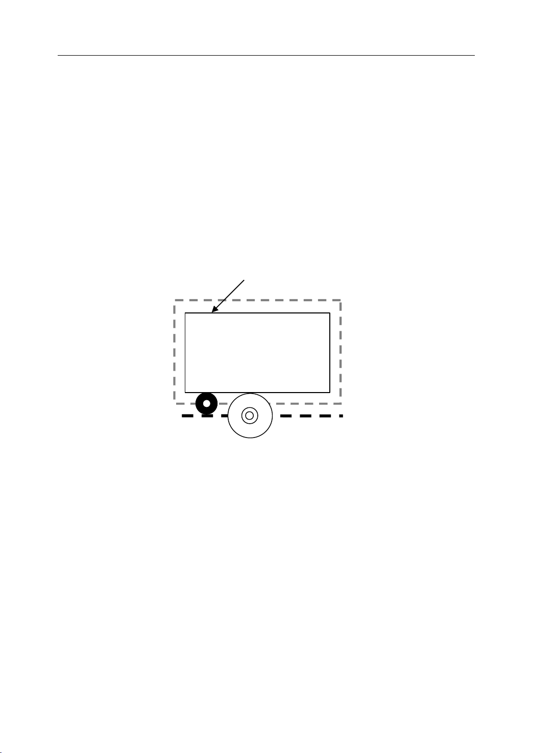
To
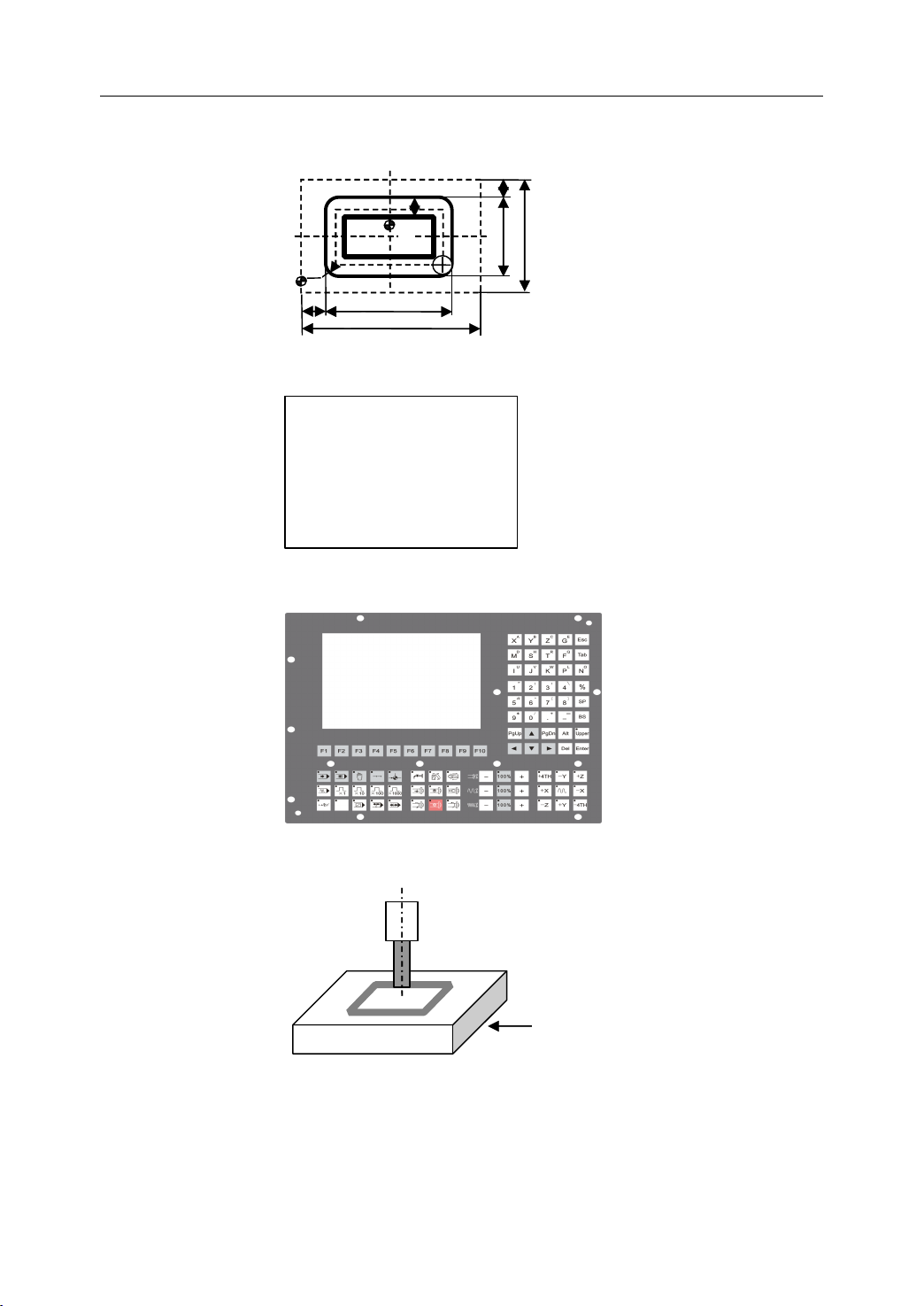
operate CNC machine tool, the first step is to understand the part drawing and produce a
program manual script. The procedure for machining a part is as follows (Figure 1.1):
1) Read drawing
2) Produce the program manual script
3) Input the program manual script by using the machine control panel
4) Manufacture a part
Programming
Programming
Programming
1. General
2
Page 7
1. Reading drawing
1. General
R
B
1
10
0
2. Programming
%3308 (the origin is on A)
N1 G92 X0 Y0 Z50
N2 M03 S500
N3 G00 X-31
N4 Z5
N5 G01 Z-3 F40
… .
3. Inputting program
8
A
7
0
Y-26
1
6
8
4. Manufacturing
Workpiece
Figure 1 . 1 The workflow of operation of CNC machine tool
3
Page 8
1. General
1.2
Interpolation
1.2
Interpolation
1.2
1.2 Interpolation
Interpolation
Interpolation refers to an operation in which the machine tool moves along the workpiece
parts. There are five methods of interpolation: linear, circular, helical, parabolic, and cubic.
Most CNC machine can provide linear interpolation and circular interpolation. The other
three methods of interpolation (helical, parabolic, and cubic interpolation) are usually used
to manufacture the complex shapes, such as aerospace parts.
1.2.1
1.2.1
1.2.1
1.2.1 L
Linear interpolation refers to the tool movement along a straight line.
1.2.2
1.2.2
1.2.2
1.2.2 Circular
Figure 1.3 shows a tool movement along an arc.
L
inear
L
inear
L inear
inear Interpolation
Circular
Circular
Circular Interpolation
Interpolation
Interpolation
Interpolation
Interpolation
Interpolation
Interpolation
Figure 1 . 2 Linear Interpolation
tool
workpiece
tool
workpiece
Figure 1 . 3 Circular Interpolation
Note:
Note:
Note:
Note:
In this manual, it is assumed that tools are moved against workpieces.
4
Page 9

1. General
1.2.3
1.2.3
1.2.3
1.2.3 Helical
Helical interpolation can be used to manufacture threads on a workpiece.
Helical
Helical
Helical Interpolation
Interpolation
Interpolation
Interpolation
Figure 1 . 4 Helical Interpolation
5
Page 10
1. General
1.3
Feed
1.3
Feed
1.3
1.3 Feed
Feed Function
- Feed refers to an operation in which the tool moves at a specified speed to cut a
workpiece.
- Feedrate refers to a specified speed, and numeric is used to specified the fe e drate .
- Feed function refers to an operation to control the fe e drate .
Function
Function
Function
m m/min
F
workp iece
T
able
Figure 1 . 5 Feed Function
For example:
F150.0 //feed the tool at 150mm/min, while the workpiece makes one turn
Tool
6
Page 11
1.4
Coordinate
1.4
Coordinate
1.4
1.4 Coordinate
Coordinate System
System
System
System
1. General
1.4.1
1.4.1
1.4.1
1.4.1 Reference
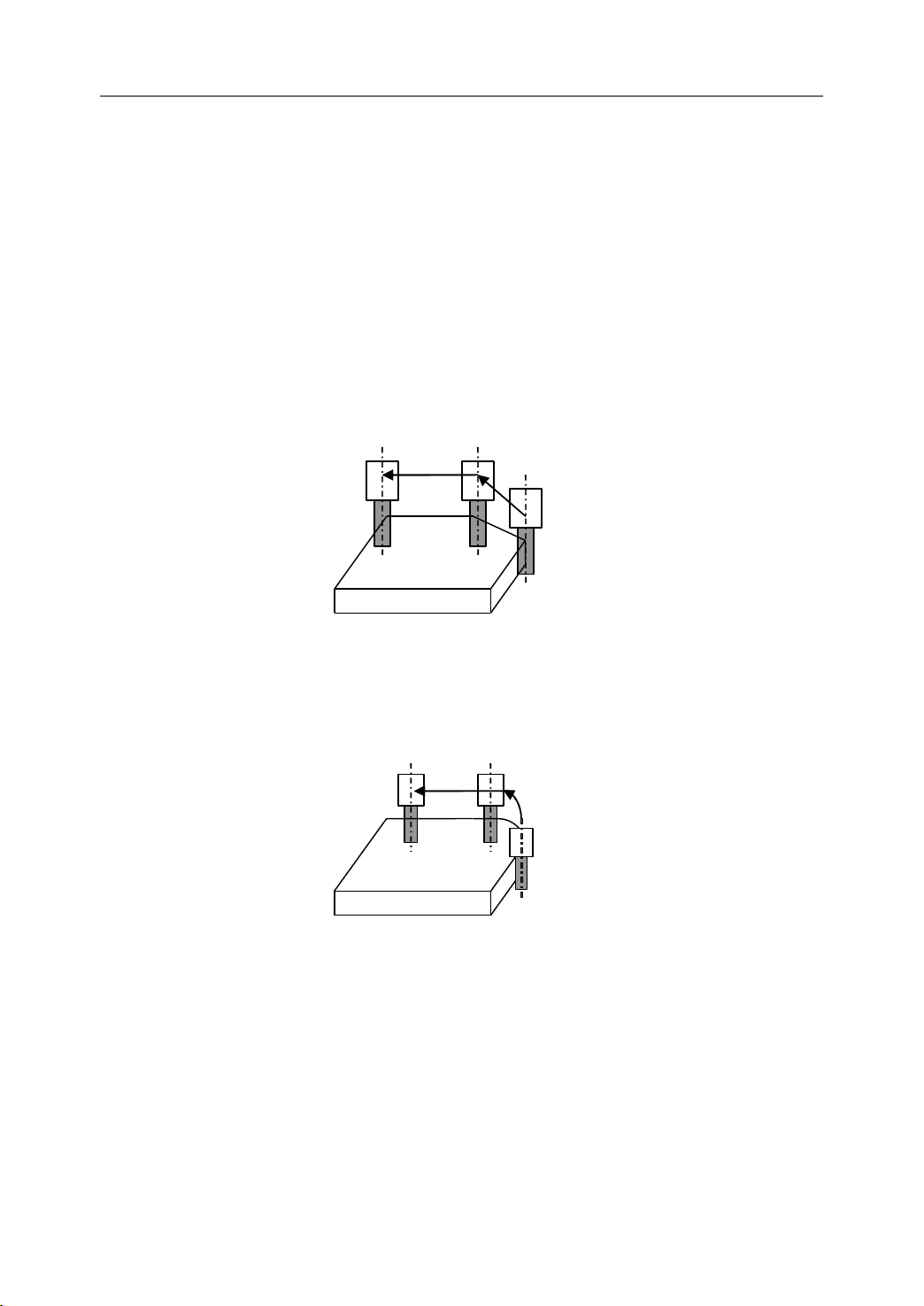
Reference point is a fixed position on CNC machine tool, which is determined by cams and
measuring system. Generally, it is used when the tool is required to exchange or the
coordinate system is required to set.
There are two ways to move to the reference point:
- Manual reference position return: The tool is moved to the reference point by operating
Reference
Reference
Reference Point
Point
Point
Point
Reference Position
Tool
workp iece
Table
Figure 1 . 6 Reference Point
the button on the machine control panel. It is only used when the machine is turned on.
- Automatic reference position return: It is used after the manual reference position return
has been used. In this manual, this would be introduced.
7
Page 12
1. General
+
X
+
X
+
Y
'
+Z+
Y
+
Z
+Y+
C
+
Z
'
+A +
B
+
C
+ X +Y +
Z
+
A
+
B
+
X
'
1.4.2
1.4.2
1.4.2
1.4.2 Machine
Machine
Machine
Machine Coordinate
Coordinate
Coordinate
Coordinate System
System
System
System
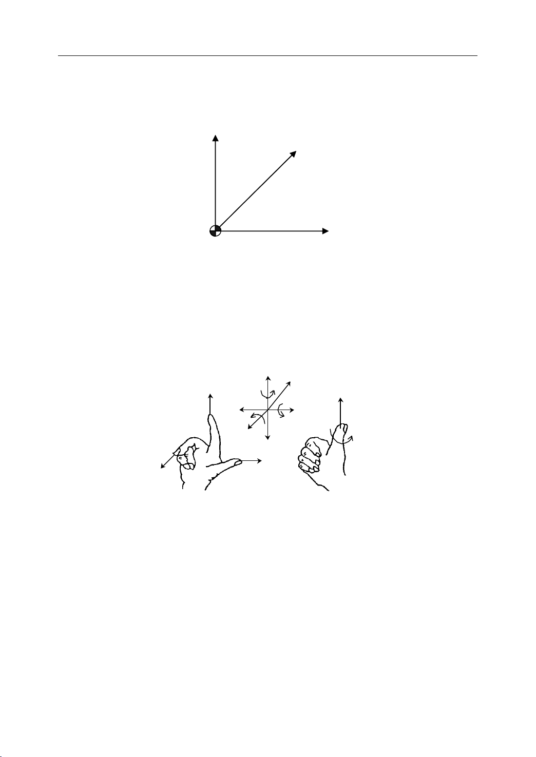
The coordinate system is set on a CNC machine tool. Figure 1.7 is a machine coordinate
system of milling machine, and shows the direction of axes:
Zm
Ym
M
Figure 1 . 7 Machine Coordinate System
In general , three basic linear coordinate axes of motion are X,
Xm
Y,
Z. Moreover, X,
Y,
Z axis
of rotation is named as A, B, C cor respond ently. Due to different types of milling machine,
the axis direction can be decided by following the rule – “ three finger rule ” of the right
hand.
Figure 1 . 8 “ three finger rule ”
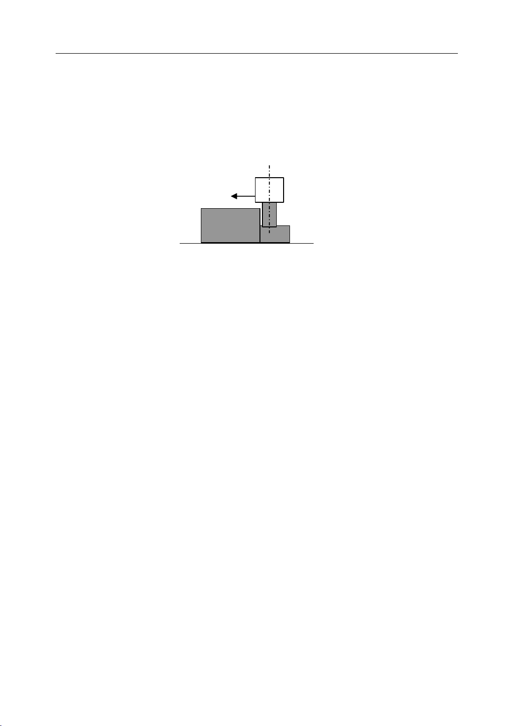
- The thumb points the X axis. X axis controls the cross motion of the cutting tool.
“ +X ” means that the tool is away from the spindle centerline
- T he index points the Y axis. Y axis is usually a virtual axis.
- T he middle finger points the Z axis. Z axis controls the motion of the cutting tool.
“ +Z ” means that the tool is away from the spindle.
8
Page 13
1. General
1.4.3
1.4.3
1.4.3
1.4.3 Workpiece
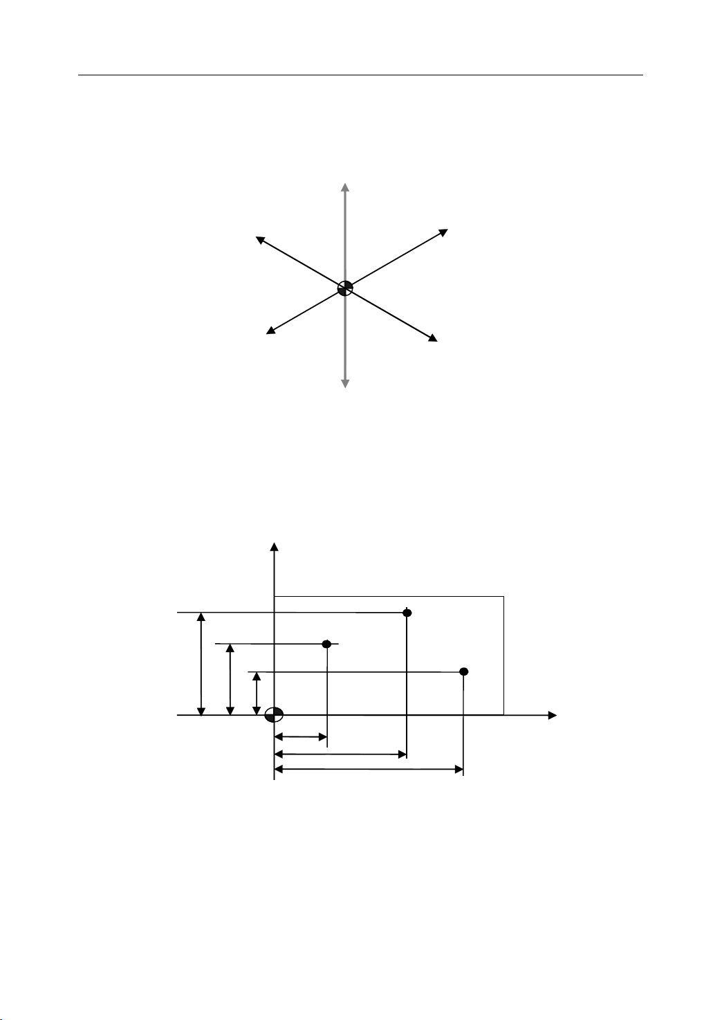
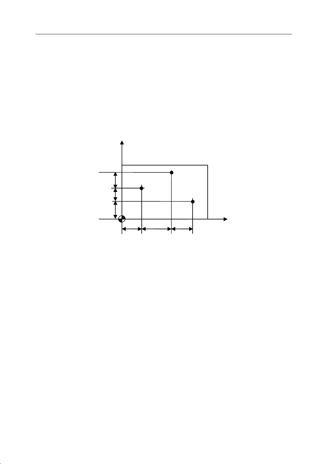
The coordinate system is set on a workpiece. The data in the NC program is from the
workpiece coordinate system.
Example: Those three points can be defined on workpiece coordinate system:
Workpiece
Workpiece
Workpiece Coordinate
P1 corresponds to X20 Y35
Coordinate
Coordinate
Coordinate System
Figure 1 . 9 Workpiece Coordinate System
System
System
System
Z+
X-
W
W
W
W
Y-
Z-
Y+
X+
P2 corresponds to X50 Y60
P3 corresponds to X70 Y20
Y
P2
P1
60
35
20
20
50
70
Figure 1 . 10 Example of defining points on workpiece coordinate system
P3
X
9
Page 14
1. General
1.4.4
1.4.4
1.4.4
1.4.4 Setting
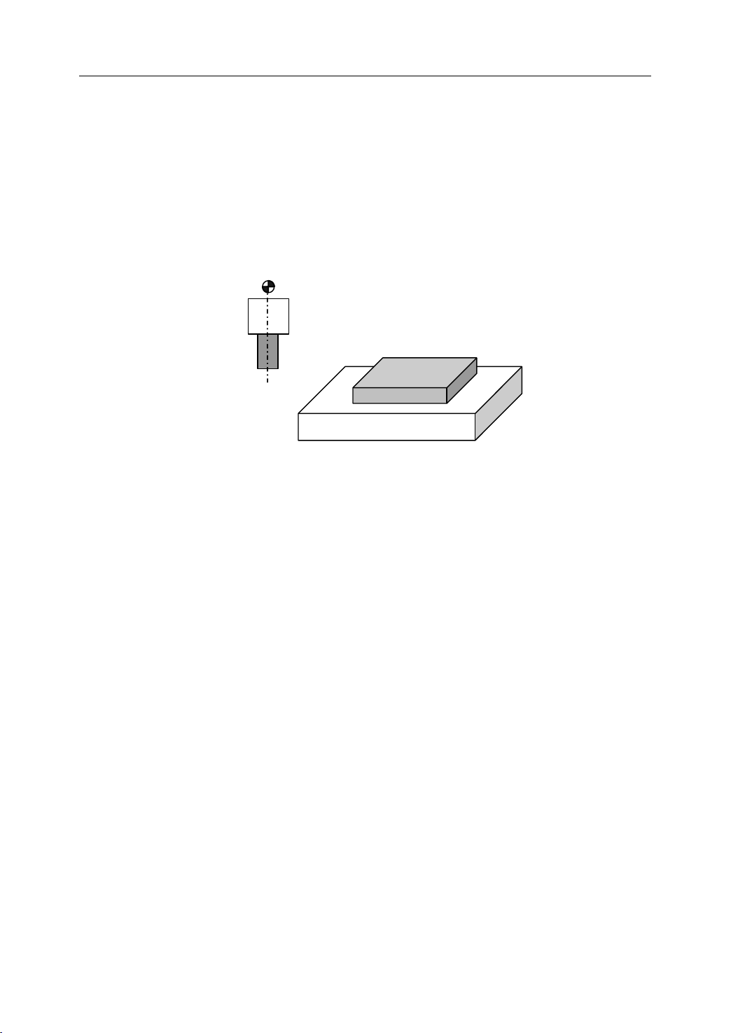
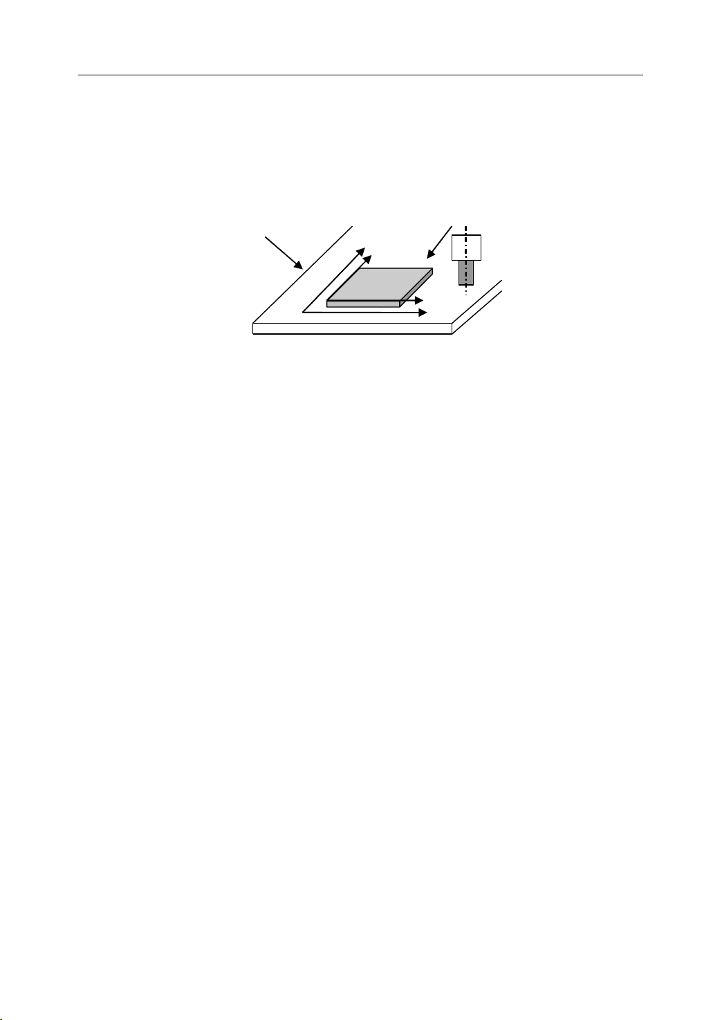
When a workpiece is set on the table, the positional relation between machine coordinate
system and workpiece coordinate system are set.
According to the command program based on the workpiece coordinate system, the tool
moves on the coordinate system specified by CNC, and cuts a workpiece.
Setting
Setting
Setting Two
Two
Coordinate
Two
Coordinate
Two Coordinate
Coordinate Systems
Coordinate system
specified by the CNC
established on the table
Figure 1 .11Setting two coordinate systems at the same position
Systems
Systems
Systems at
Y
Y
workpiece
Table
at
the
at
at the
Same
the
Same
the Same
Same Position
Coordinate system on
part drawing established
on the work-piece
X
X
Position
Position
Position
10
Page 15
1. General
1.4.5
1.4.5
1.4.5
1.4.5 Absolute
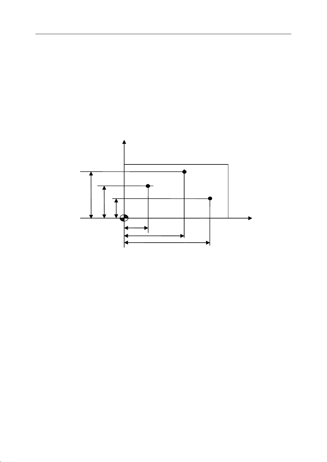
The absolute dimension describes a point at “ the distance from zero point of the coordinate
system ” .
E xample: These three point in absolute dimensions are the following:
Absolute
Absolute
Absolute Commands
P1 corresponds to X20 Y35
P2 corresponds to X20 Y60
P3 corresponds to X70 Y20
60
Commands
Commands
Commands
35
20
Y
P2
P1
P3
X
20
50
70
Figure 1 . 12 Absolute Dimension
11
Page 16
1. General
1.4.6
1.4.6
1.4.6
1.4.6 Incremental
The incremental dimension describes a distance from the previous tool position to the next
tool position.
Example: These three point in incremental dimensions are the following:
Incremental
Incremental
Incremental Commands
P1 corresponds to X20 Y35 //with reference to the zero point
P2 corresponds to X30 Y20 //with reference to P1
P3 corresponds to X20
Commands
Commands
Commands
Y-35
Y
20
15
20
P1
//with reference to P2
P2
P3
3020
20
X
Figure 1 . 13 Incremental Dimension
12
Page 17
1. General
1.4.7
1.4.7
1.4.7
1.4.7 Polar
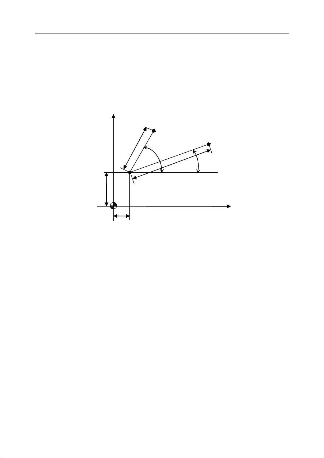
Beside the “ Cartesian coordinate system ” , another way to specify coordinates is “ polar
coordinates ” . The polar coordinate method is useful only if there is radius and angle
measurements on a workpiece.
Example: Two points P1 and P2 with reference to the pole are described as follows.
Polar
Polar
Polar Coordinates
Coordinates
Coordinates
Coordinates
Y
30
Pole
P2
P1
60
75 °
100
15
30 °
X
Figure 1 . 14 Polar Coordinates
P1 corresponds to radius=100 plus angle=30 °
P2 corresponds to radius=60 plus angle=75 °
13
Page 18
1. General
1.5
Spindle
1.5
Spindle
1.5
1.5 Spindle
Spindle Speed
The cutting speed (v) refers to the speed of the tool with respect to the workpiece when the
workpiece is cut. The unit of the cutting speed is m/min. As for the CNC, the cutting speed
can be specified by the spindle speed (N) in min-1.
The formula to get the spindle speed is:
Speed
Speed
Speed Function
Spindle speed N
Figure 1 . 15 Cutting Speed and Spindle Speed
Function
Function
Function
-1
m in
workpiece
T
Tool
Tool diameter
D mm
V: Cutting speed m/min
able
v
N
∗=1000
D
π
N: the spindle speed
v: cutting speed
D: diameter value of the workpiece
Example: When the diameter of workpiece is 100mm, and the cutting speed is 80m/min,
v
then the spindle speed:
N
=
∗
=
D
The constant surface speed refers to the speed even when the workpiece diameter is changed,
and the CNC changes the spindle speed. At this time, the spindle speed is the cutting speed.
8010001000
∗
≈
100
∗
ππ
mr
/250
14
Page 19
1.6
Tool
1.6
Tool
1.6
1.6 Tool
Tool Function
Function
Function
Function
1. General
1.6.1
1.6.1
1.6.1
1.6.1 Tool
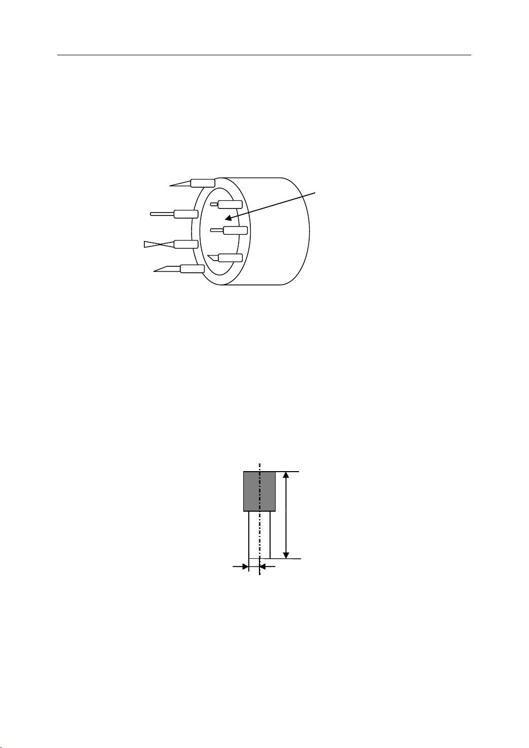
It is necessary to select a suitable tool when drilling, tapping, boring or the like is performed.
As it is shown in Figure 1.16, a number is assigned to each tool. Then this number is used in
the program to specify that the corresponding tool is selected.
1.6.2
1.6.2
1.6.2
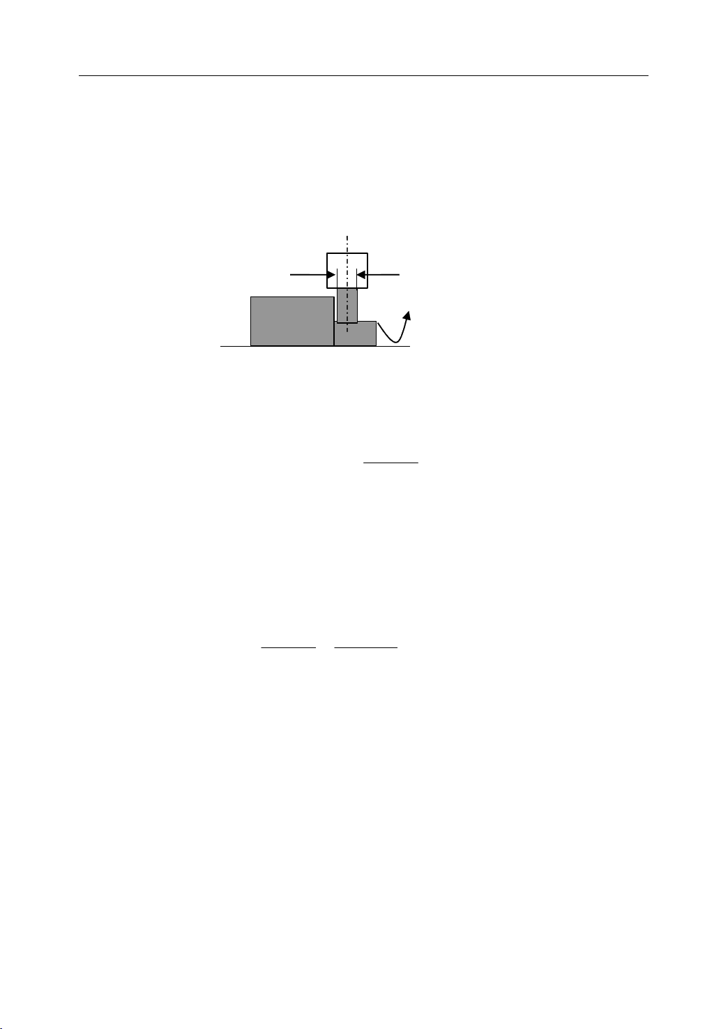
1.6.2 Tool
When writing a program, the operator just use the workpiece dimensions according to the
dimensions in the part drawing. The tool nose radius center and the tool length are not taken
Tool
Selection
Tool
Selection
Tool Selection
Selection
Tool
Offset
Tool
Offset
Tool Offset
Offset
01
01
01
01
02
02
02
02
Figure 1 . 16
Tool
Tool number
Selection
into account. However, when machining a workpiece, the tool path is affected by the tool
geometry. There are two kinds of tool offset: tool length compensation and tool radius
compensation.
Length
Radius
Figure 1 . 17 Length compensation and Radius compensation
15
Page 20
1. General
Tool Length Compensation
There are two kind of ways to specify the value of tool length compensation.
- Absolute value of tool compensation (the distance between tool tip and machine
reference point)
- Incremental value of tool compensation (the distance between tool tip and the
standard tool)
Tool Radius Compensation
Figure 1. 18 shows the difference between the programmed contour and the corrected tool
path.
Programmed contour
Corrected tool path
Figure 1 . 18 Difference between programmed contour and corrected tool path
16
Page 21

1. General
1.7
Miscellaneous
1.7
Miscellaneous
1.7
1.7 Miscellaneous
Miscellaneous Function
Miscellaneous function refers to the operation to control the spindle, feed, and coolant. In
general, it is specified by an M code.
When a move command and M code are specified in the same block, there are two ways to
execute these commands:
1) Pre-M function
M command is executed before the completion of move command
2) Post-M function
M command is executed after the completion of move command.
The sequence of the execution depends on the specification of the machine tool builder.
Function
Function
Function
17
Page 22
1. General
Program
1.8
Program
1.8
Program
Program Configuration
1.8
1.8
1.8.1
1.8.1
1.8.1
1.8.1 Structure
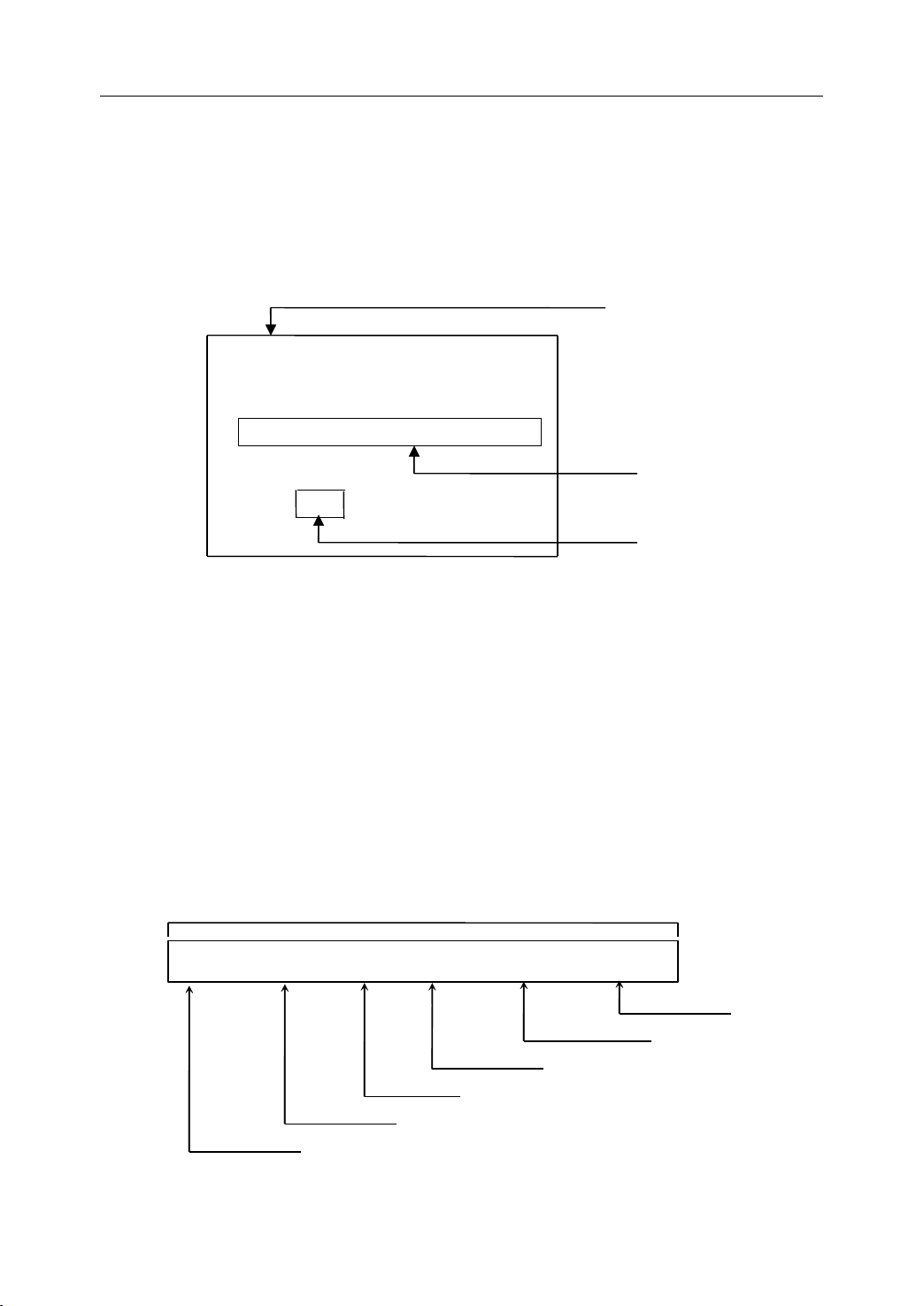
As it is shown in Figure 1.19, an NC program consists of a sequence of NC blocks
block is one of machining steps. Commands
Structure
Structure
Structure of
- Format of program
Configuration
Configuration
Configuration
of
an
NC
of
an
of an
an NC
%1000
N01 G91 G00 X50 Y60
N10 G01 X100 Y500 F150 S300 M03
N...... ;COMMENT
N200 M30
Figure 1 . 19 Structure of an NC Program
program
program
program name
name
name
name
Program
NC
Program
NC Program
Program
Commands
Commands
Commands in each block are the instruction.
Program
Program block
Command character
blocks
blocks
blocks . Each
The program name must be specified in the format OXXXX (X could be letters or
numbers).
program
- Format of program
T he program number should be started with %XXXX or OXXXX (X could be numbers
only).
- Format of blocks
A
block starts with the program block number.
N.. G.. X … Y …
program
program number
blocks
blocks
blocks
Program block number
number
number
number
Program block
F..
Feed Function
Coordinate - Dimension word
Preparatory function
Figure 1 . 20 Structure of Block
M.. S..
Spindle function
Miscellaneous function
18
Page 23
end
Instruction 1
Instruction 2
Instruction n
Instruction n+1
Follow the direction
of the subprogram
Instruction 1
Instruction 2
Return to the main program
Main program
Subprogram
of
- Format of end
The last block should contain M02 or M03 to indicate the end of program.
- Format of Comments
All information after the “ ; ” is regarded as comments.
All information between “ ( ) ” is regarded as comments.
end
end of
Comments
Comments
Comments
program
of
program
of program
program
1. General
1.8.2
1.8.2
1.8.2
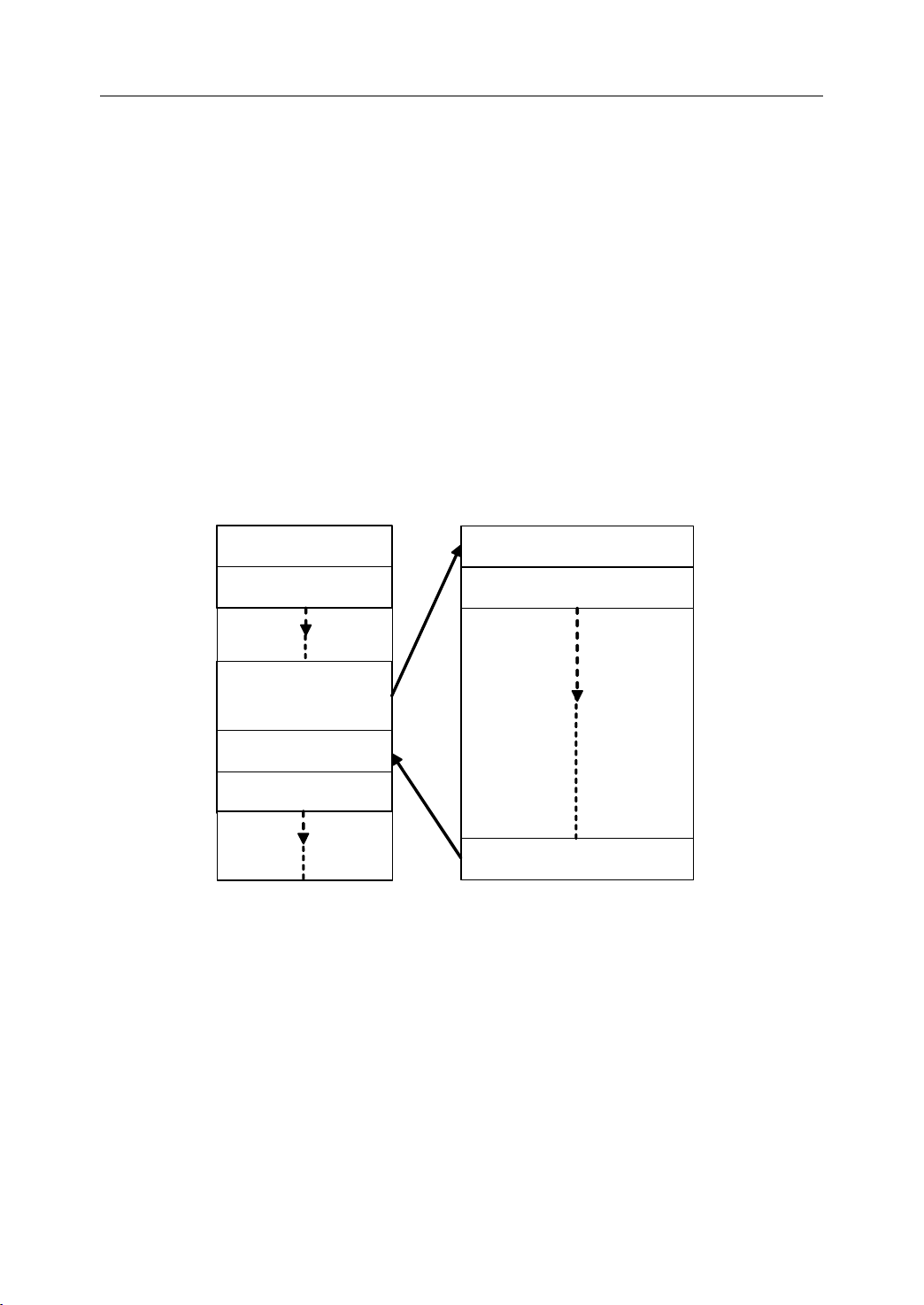
1.8.2 Main
There are two type of program: main program and subprogram. The CNC operates
according to the main program. When a execution command of subprogram is at the
execution line of the main program, the subprogram is called. When the execution of
subprogram is finished, the system returns control to the main program.
Main
Main
Main Program
Program
Program
Program and
and
Subprogram
and
Subprogram
and Subprogram
Subprogram
Note:
Note:
Note:
Note:
Main program and its subprogram must be written in a same file with a different program
codes.
Figure 1 . 21 Main program and subprogram
19
Page 24

2
Preparatory
2
Preparatory
2
2 Preparatory
Preparatory Function
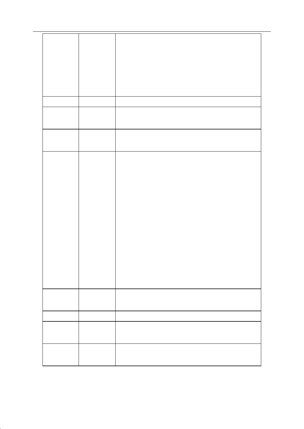
There are two types of G code: one-shot G code, and modal G code.
Type
Type
Type
Type Meaning
One-shot G code The G code is only effective in the block in which it is specified
Modal G code The G code is effective until another G code is specified.
Example : G01 and G00 are modal G codes.
N10 G01 X 100;
Meaning
Meaning
Meaning
Function
Function
Function (G
Table 2 1 Type of G code
(G
(G
(G code)
code)
code)
code)
2. Preparatory Function
N20 Y200 X200;
N30 X300;
N40 G00 Y100;
G01 is effective from N10 to N30
20
Page 25

2.1
G
2.1
2.1
2.1 G
code
G
code
G code
code List
List
List
List
The following table is the list of G code in HNC system.
Table 2 2 G code list
G
code
G
code
G
G code
code G
G
roup
G
roup
G roup
roup function
function
function
function
2. Preparatory Function
G00
◣ G01
G02 Circular interpolation/Helical interpolation CW
G03 Circular interpolation/Helical interpolation CCW
G04 00 Dwell
G07 00 Virtual axis
G09 00 Exact stop
◣ G17
G18 ZX plane selection
G19 YZ plane selection
G20
◣ G21
G22 Input in i mpulses equivalent weight
G24
◣ G25
G28
G29 Return from reference point
01
02
08
03
00
Rapid positioning
Linear interpolation
XY plane selection
Input in inch es
Input in m etrics
Programmable mirror image
Programmable mirror image cancel
Return to reference point
G34 00 Thread tapping
G38 00 Polar Coordinates
◣ G40
G41 Cutter compensation left
G42 Cutter compensation right
G43
G44 Tool length compensation - direction
◣ G49
◣ G50
G51 Scaling
09
10
04
Cutter compensation cancel
Tool length compensation +direction
Tool length compensation cancel
Scaling cancel
21
Page 26

G53 00 Machine coordinate system selection
2. Preparatory Function
22
Page 27
G54
Workpiece coordinate system 1
G55 Workpiece coordinate system 2
2. Preparatory Function
G56 Workpiece coordinate system 3
11
G57 Workpiece coordinate system 4
G58 Workpiece coordinate system 5
G59 Workpiece coordinate system 6
G60 00 Single direction positioning
◣ G61
Exact stop mode
12
G64 Cutting mode
G68
Coordinate rotation
05
◣ G69
G73
Coordinate rotation cancel
High-speed drilling cycle
G74 Left-hand tapping cycle
G76 Fine boring cycle
◣ G80
Canned cycle cancel
G81 Drilling cycle , Spot drilling
G82 Drilling cycle , Counter boring cycle
G83 Peck drilling cycle
06
G84 Tapping cycle
G85 Boring cycle
G86 Boring cycle
G87 Back boring cycle
G88 Manual Boring cycle
G89 Boring cycle
◣ G90
Absolute command
13
G91 Increment command
G92 00 Setting for work coordinate system
◣ G94
Feed per minute
14
G95 Feed per r otation
◣ G98
Return to initial point in canned cycle
15
G99 Return to R point in canned cycle
23
Page 28

2. Preparatory Function
Explanation:
Explanation:
Explanation:
Explanation:
1) G codes in 00 group are one-shot G code, while the other groups are modal G
code.
2)
3) Multiple G codes from different groups can be specified in the same block. If
means that it is default setting.
◣
multiple G codes from the same group are specified in the same block, only the
last G code specified is valid .
24
Page 29

3
Interpolation
3
Interpolation
3
3 Interpolation
Interpolation Functions
This chapter would introduce:
1) Positioning Command (G00)
2) Single Direction Positioning (G60)
3) Linear Interpolation (G01)
4) Circular Interpolation (G02, G03)
5) Helical Interpolation (G02, G03)
6) Thread Tapping (G34)
Functions
Functions
Functions
3. Interpolation Function
25
Page 30
3.1
Positioning
3.1
Positioning
3.1
3.1 Positioning
Positioning (G00)
Programming
Programming
Programming
Programming
G00 X_Y_Z_A_
(G00)
(G00)
(G00)
3. Interpolation Function
Explanation
Explanation
Explanation
Explanation of
X,Y,Z, A Coordinate value of the end point in the absolute command or incremental
command
Function
Function
Function
Function
The tool is moved at the highest possible speed (rapid traverse). I f the rapid traverse
movement is required to execute simultaneously on several axes, the rapid traverse speed is
decided by the axis which takes the most time. Thus, the tool path is nonlinear. The operator
can use this function to position the tool rapidly, to travel around the workpiece, or to
approach the tool change position.
Example
Example
Example
Example
Move tool from
of
the
parameters
of
the
parameters
of the
the parameters
parameters
A
(20, 15) to B (90, 45) at the rapid traverse speed.
Non linear interpolation
Y
positioning
C
B
Absolute programming:
G00 X90 Z45
Incremental programming:
G00 X70 Y30
15
O
Figure 3 . 1 Positioning (Rapid Traverse)
A
20 90
50
26
X
Page 31

3.2
Single
3.2
Single
3.2
3.2 Single
Single Direction
Programming
Programming
Programming
Programming
G60 X_ Y_ Z_ A_
Direction
Direction
Direction Positioning
Positioning
Positioning
Positioning (G60)
(G60)
(G60)
(G60)
3. Interpolation Function
Explanation
Explanation
Explanation
Explanation of
X,Y,Z, A Coordinate value of the end point in the absolute command or incremental
command
Function
Function
Function
Function
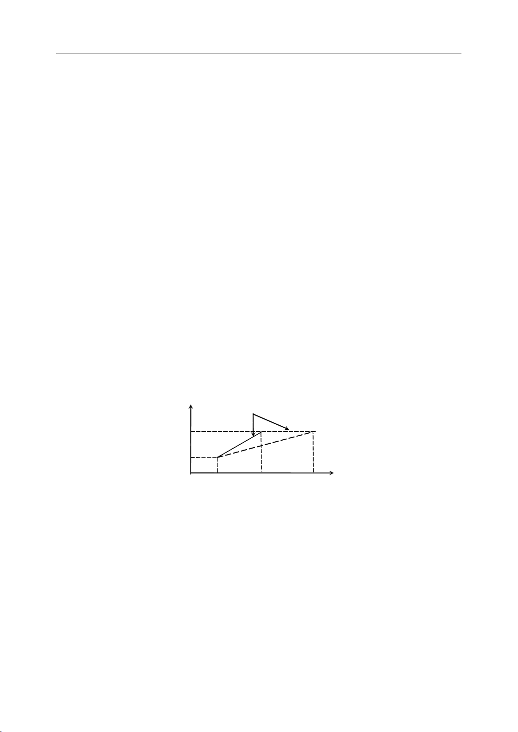
At first, move the tool from the start point to the intermediate point at the rapid traverse
speed. Then, tool is moved from the intermediate point to the end point at the specified
fe e drate .
of
the
parameters
of
the
parameters
of the
the parameters
parameters
Start position
Overrun
intermediate point
Start position
End position
Figure 3 . 2 Single Direction Positioning (G60)
Note:
Note:
Note:
Note:
The direction and distance from the intermediate point to the end point are set by machine
parameter – single direction positioning offset. When the value of the parameter is less than
0, the direction is negative. When the value of the parameter is more than 0, the direction is
positive.
27
Temporary stop
Page 32

3.3
Linear
3.3
Linear
3.3
3.3 Linear
Linear Interpolation
Programming
Programming
Programming
Programming
G01 X_ Y_ Z_ A_ F_
Interpolation
Interpolation
Interpolation (G01)
(G01)
(G01)
(G01)
3. Interpolation Function
Explanation
Explanation
Explanation
Explanation of
X,Y,Z, A Coordinate value of the end point in the absolute command or incremental
command
F Feedrate. It is effective until a new value is specified.
Function
Function
Function
Function
The tool is moved along the straight line at the specified fe e drate .
Example
Example
Example
Example 1
Move tool from
of
of
of the
1
1
1
the
parameters
the
parameters
the parameters
parameters
A
(20, 15) to B (90, 45) at the rapid traverse speed.
Y
15
O
linear interpolation
A
20 90
45
Figure 3 . 3 Linear Interpolation – Example 1
B
X
A bsolute programming
G01 X90 Y45 F800
Incremental programming
G01 X70 Y30 F800
28
Page 33

Example
Example
Example
Example 2
2
2
2
Use the tool (Φ8) to machine a groove (3mm) on a workpiece.
8
A
R4
B
15
Figure 3 . 4 Linear Interpolation – Example 2
70
100
3. Interpolation Function
10
60
80
%3308 (the origin is on A)
N1 G92 X0 Y0 Z50
N2 M03 S500
N3 G00 X-31
Y-26
N4 Z5
N5 G01 Z-3 F40
N6 Y26 F100
N7 X31
N8
Y-26
N9 X-31
N10 G00 Z50
N11 X0 Y0
N12 M05
N13 M30
%3309 (the origin is on B)
N1 G92 X0 Y0 Z50
N2 M03 S50 0
N3 G00 X19 Y14
N4 Z5
N5 G01 Z-3 F40
N6 Y66 F100
N7 X81
N8 Y14
N9 X19
N10 G00 Z50
N11 X0 Y0
N12 M05
N13 M30
29
Page 34

3.4
Circulation
3.4
Circulation
3.4
3.4 Circulation
Circulation Interpolation
Programming
Programming
Programming
Programming
Interpolation
Interpolation
Interpolation (G02,
(G02,
(G02,
(G02, G03)
G03)
G03)
G03)
3. Interpolation Function
G02
⎫
⎧
G17
⎨
⎩
⎧
G18
⎨
⎩
⎧
G19
⎨
⎩
Explanation
Explanation
Explanation
Explanation of
G17 The working plane is
G18 The working plane is XZ, and the infeed direction is Y
G19 The working plane is YZ, and the infeed direction is X
G02 a circular path in c lockwise direction (CW) (Figure 3.5)
G03 a circular path in counterc lockwise direction ( C CW)
G02 and G03 are defined when the working plane is specified. Figure 3.5 shows the
direction of circular interpolation.
G03
G02
G03
G02
G03
⎬
⎭
⎫
⎬
⎭
⎫
⎬
⎭
X_Y_
X_ Z_
Y_ Z_
I_J_
⎧
⎨
R_
⎩
I_ K_
⎧
⎨
R_
⎩
J_ K_
⎧
⎨
R_
⎩
of
the
parameters
of
the
parameters
of the
the parameters
parameters
⎫
F_
⎬
⎭
⎫
F_
⎬
⎭
⎫
F_
⎬
⎭
XY,
and the infeed direction is Z
Y
G02
G 17
Figure 3 . 5 Direction of circular interpolation
X, Y/X,
the specific working plane. For an incremental command, the coordinate values of the
circle end point with reference to the circle starting point in the specific working plane.
Z/Y,
Z For an absolute command, the coordinate values of the circle end point in
X
G03
G02
X
30
G03
G 18
Z
G03
G02
Z
G 19
Y
Page 35

3. Interpolation Function
I, J/I, K/J, K Coordinate values of the circle center point with reference to the circle
starting point in incremental command. (Figure 3.6)
Y
1
1
1
1
R Circle radius. When the arc is less than 180 ° (minor arc) , R is positive . If
the arc is more than 180 ° (major arc), R is negative.
F Feedrate along the circle
Function
Function
Function
Function
The tool is moved along a full circle or arcs.
E nd point (X, Y)
X
Centre
Start
point
I
Figure 3 . 6 Distance from the start point to the circle centre point
X
5
5
5
5
3
3
3
3
J
E nd point (X, Z)
Z
4
4
4
4
Centre
Z
Start
point
I
K
2
2
2
2
End point
Y
Centre
(Y,
Z)
Start
point
J
K
Note:
Note:
Note:
Note:
1) When it is full circle programming, R can not be used in the program. I, J, K can
only be used in this case.
2) When it is not full circle programming, the operator can select R or I, J, K to
program. I f I, J, K, and R addresses are all specified in the program , R tak es
precedence and the other are ignored.
31
Page 36

Example
Example
Example
Example 1
1
1
1
Use G02 to program the minor arc a and the major arc b.
3. Interpolation Function
(i) Arc a
G91 G02 X30 Y30 R30 F300
G91 G02 X30 Y30 I30 J0 F300
G90 G02 X0 Y30 R30 F300
b
R
30
a
a
Start point
Figure 3 . 7 Circular Interpolation – Example 1
Y
End
point
R30
X
6
6
6
6
G90 G02 X0 Y30 I30 J0 F300
(ii) Arc b
G91 G02 X30 Y30 R- 30 F300
G91 G02 X30 Y30 I0 J30 F300
G90 G02 X0 Y30 R- 30 F300
G90 G02 X0 Y30 I0 J30 F300
32
Page 37

Example
Example
Example
Example 2
2
2
2
Use G02/G03 to program the full circle.
Figure 3 . 8 Circular Interpolation – Example 2
3. Interpolation Function
Y
R
30
X
O
B
A
i ) Clockwise circle from
A
to A
G90 G02 X30 Y0 I- 30 J0 F300
G91 G02 X0 Y0 I- 30 J0 F300
(ii) Counterclockwise circle from B to B
G90 G03 X0
Y-
30 I0 J30 F300
G91 G03 X0 Y0 I0 J30 F300
33
Page 38

Example
Example
Example
Example 3
3
3
3
Use the tool (Φ8) to machine a groove (3mm) on a workpiece.
R10
R10
20
20
R20
R20
30
30
Figure 3 . 9 Circular Interpolation – Example 3
R20
R20
%3314
N1 G92 X0 Y0 Z50
3. Interpolation Function
R10
R10
N2 M03 S500
N3 G00 X10 Y30
N4 Z5
N5 G01 Z-3 F40
N6 X30
N7 G02 X38.66 Y25 R10
(N7 G02 X38.66 Y25 J-10)
N8 G01 X47.32 Y10
N9 G02 X30
(N9 G02 X30
Y-20
Y-20
R20
J-10 I-17.32)
N10 G01 X0
N11 G02 X0 Y20 R20
(N11 G02 X0 Y20 J20)
N12 G03 X10 Y30 R10
(N13 G03 X10 Y30 J10)
N14 G00 Z50
N15 X0 Y0
N16 M30
34
Page 39

Example
Example
Example
Example 4
Use the tool (Φ8) to machine a groove (3mm) on a workpiece.
%3315
N1 G92 X0 Y0 Z50
4
4
4
20
20
R10
R10
R20
R20
Figure 3 . 10 Circular Interpolation – Example 4
3. Interpolation Function
N2 M03 S500
N3 G00 X-25 Y-8.66
N4 Z5
N5 G01 Z-3 F40
N6 G02 X-25 Y8.66 R10
N7 G01 X-10 Y17.32
N8 G02 X-10 Y-17.32 R-20
N9 G01 X-25 Y-8.66
N10 G00 Z50
N11 X0 Y0
N12 M05
N13 M30
3.5
Helical
3.5
Helical
3.5
3.5 Helical
Helical Interpolation
Interpolation
Interpolation
Interpolation (G02,
(G02,
(G02,
(G02, G03)
35
G03)
G03)
G03)
Page 40

Programming
Programming
Programming
Programming
3. Interpolation Function
G02
⎫
⎧
G17
⎨
⎩
⎧
G18 Y_F_
⎨
⎩
⎧
G19 X_F_
⎨
⎩
Explanation
Explanation
Explanation
Explanation of
G17 The working plane is
G18 The working plane is XZ, and the infeed direction is Y
G19 The working plane is YZ, and the infeed direction is X
G02 a circular path in c lockwise direction (CW) (Figure 3.5)
G03 a circular path in counterc lockwise direction ( C CW)
X, Y/X,
the specific working plane. For an incremental command, the coordinate values of the
X_Y_
⎬
G03
⎭
G02
⎫
X_Z_
⎬
G03
⎭
G02
⎫
Y_Z_
⎬
G03
⎭
Z/Y,
I_J_
⎫
⎧
⎬
⎨
R_
⎭
⎩
I_K_
⎧
⎨
⎩
⎧
⎨
⎩
of
the
of
the
of the
the parameters
Z For an absolute command, the coordinate values of the circle end point in
⎫
⎬
R_
⎭
J_K_
⎫
⎬
R_
⎭
parameters
parameters
parameters
Z_F_
L
L
L
XY,
and the infeed direction is Z
circle end point with reference to the circle starting point in the specific working plane.
I, J/I, K/J, K Coordinate values of the circle center point with reference to the circle
starting point in incremental command.
R Circle radius. When the arc is less than 180 ° (minor arc) , R is positive . If
the arc is more than 180 ° (major arc), R is negative.
Z, Y, X The coordinate value of the end point with reference to the starting point on
the third axis in the incremental command.
F Feedrate along the circle
L Number of circles on a workpiece
Figure 3 .11Helical Interpolation (G02, G03)
Function
Function
Function
Function
Helical interpolation can be used to manufacture threads on the workpiece.
36
Page 41

3. Interpolation Function
Example
Example
Example
Example 1
Use G03 to program.
Absolute programming
1
1
1
G90 G17 F300
G03 X0 Y30 R30 Z10
Z
10
O
30
Start point
X
7
7
7
7
Figure 3 . 12 Helical Interpolation – Example 1
End point
30
Y
Incremental programming
G91 G17 F300
G03 X-30 Y30 R30 Z10
37
Page 42

3. Interpolation Function
Example
Example
Example
Example 2
2
2
2
Use the tool (Φ10mm) to machine a hole (the diameter is 50mm, and the height is 10mm)
on a workpiece.
R25
10
Figure 3 . 13 Helical Interpolation – Example 2
%3317
N1 G92 X0 Y0 Z30
N2 G01 Z11 X20 F200
N3 G91 G03 I-20 Z-1 L11
N4 G03 I-20
N5 G90 G01 X0
N6 G00 Z30
N7 X30
Y-50
N8 M30
38
Page 43

3.6
Virtual
3.6
Virtual
3.6
3.6 Virtual
Virtual Axis
Programming
Programming
Programming
Programming
G07 X_Y_Z_A
Axis
Axis
Axis (G07)
(G07)
(G07)
(G07) and
and
and
and Sine
Sine
Sine
Sine Interpolation
Interpolation
Interpolation
Interpolation
3. Interpolation Function
Explanation
Explanation
Explanation
Explanation of
X,Y,Z, A One of axes is set as the virtual axis.
If it is set to 0, then that axis is the virtual axis. If it is set to 1, then that axis is the actual
axis.
Function
Function
Function
Function
G07 command can be used with helical interpolation command (G02, G03). The operation
combined G07 and G02/G03 is called sine interpolation.
Note
Note
Note
Note
The tool would not be moved along the virtual axis.
Example
Example
Example
Example 1
Use G03 to program
of
of
of the
1
1
1
the
parameters
the
parameters
the parameters
parameters
Y
100
G90 G00 X-50 Y0 Z0
G07 X0 G91
G03 X0 Y0 I0 J50 Z60 F800
50
Z
O
Figure 3 . 14 Sine Interpolation – Example 1
39
60
Page 44

Example
Example
Example
Example 2
To
2
2
2
implement the sine interpolation on the working plane
Z × Z+Y × Y = R × R (R: radius)
Y=R SIN ( 2 π× X/L ) (L: the distance on Z axis for each cycle)
3. Interpolation Function
XY.
%3319
N01 G92 X0 Y0 Z0
N02 G07 Z0
N03 G19 G90 G03
N04 G07 Z1
N05 M30
Y
R5
Y.0
Y
10
5
Z
50
Figure 3 . 15 Sine Interpolation – Example 2
0
Z0 J5 K0 X20.0 F100
X
40
Page 45

3.7
Tapping
3.7
Tapping
3.7
3.7 Tapping
Tapping (G34)
Programming
Programming
Programming
Programming
G34 K _ F _ P _
(G34)
(G34)
(G34)
3. Interpolation Function
Explanation
Explanation
Explanation
Explanation of
K The distance from the starting point to the bottom of the hole
F Thread lead. If it is positive , the spindle turns clockwise during tapping. If it is negative,
the spindle turns counterclockwise during tapping.
P Dwell time at the bottom of a hole. (The unit is seconds.)
Function
Function
Function
Function
With this command, the operator can rigid tap a thread.
Note
Note
Note
Note
1) When the spindle turns clockwise during tapping, the spindle would turn
2) When the spindle turns counterclockwise during tapping, the spindle would turn
In general, there is overshoot of the tap at the bottom of the thread during the
of
the
parameters
of
the
parameters
of the
the parameters
parameters
counterclockwise during retraction.
clockwise during retraction.
spindle-braking portion of the tapping cycle. It can be set by PMC parameters (Table 3-1) to
eliminate the overshoot errors.
41
Page 46

Table 3 1 PMC parameters
CNC
system
CNC
system
CNC
CNC system
system PMC
#0062 Maximum spindle speed during tapping
PMC
parameters
PMC
parameters
PMC parameters
parameters
3. Interpolation Function
HNC 18/19i
#0063 Minimum spindle speed during tapping
#0064
#0065
Dwell unit for tapping
Optional dwell unit for tapping
#0017 Maximum spindle speed during tapping
#001 8 Minimum spindle speed during tapping
HNC 21/22
#001 9
#00 30
Dwell unit for tapping
Optional dwell unit for tapping
Optional dwell unit for tapping is only effective when “ dwell unit for tapping ” is assigned to
“ 0 ” . Moreover, it is not necessary to restart the system.
The following formular is to calculate the dwelled unit (X):
D = (S * S / C) * X / 10000 = L * 360 / F
D dwell amount
S spindle speed
C Transmission gear ratio
X dwell unit
L overshoot error
F thread lead
.
42
Page 47

Example
Example
Example
Example
Use G34 to program.
3. Interpolation Function
%0002
G92 X-20
Y-20
2-M10××
2-M10
20
20
20
20
12
12
12
12
20
20
20
20
20
20
20
20
Figure 3 . 16 T apping - Example
1.5
1.5
80
80
80
80
80
80
80
80
Z50
M03 S200
G 00 X20 Y12
Z5
G34 K-27 F1.5
G00 X100
G34 K-27 F1.5
G00 Z50
X-20
Y-20
M05
M30
43
Page 48

4
Feed
4
Feed
4
4 Feed
Feed Function
This chapter would introduce:
1) Rapid Traverse
The tool is moved at the rapid traverse speed set in CNC.
2) Cutting Feed
The tool is moved at the programmed cutting feedrate.
3) Dwell
4) Exact Stop
5) Cutting Mode
Function
Function
Function
4. Feed Function
44
Page 49

4. Feed Function
4.1
Rapid
4.1
Rapid
4.1
4.1 Rapid
Rapid Traverse
Positioning command (G00) is to move the tool at the rapid traverse speed (the highest
possible speed).
This rapid traverse speed can be controlled by the machine control panel. For more detailed
information, please refer to turning operation manual.
Traverse
Traverse
Traverse (G00)
(G00)
(G00)
(G00)
45
Page 50

4.2
Cutting
4.2
Cutting
4.2
4.2 Cutting
Cutting Feed
Programming
Programming
Programming
Programming
G94 [F_ ]
G95 [F_ ]
Feed
Feed
Feed (G94,
(G94,
(G94,
(G94, G95)
G95)
G95)
G95)
4. Feed Function
Explanation
Explanation
Explanation
Explanation of
G94 feedrate per minute.
On linear axis, the unit of feedrate is mm/min, or in/min.
On rational axis, the unit of feedrate is degree/min.
G95 feedrate per revolution
The unit of feedrate is mm/rev, or in/rev.
Note:
Note:
Note:
Note:
1) G94 is the default setting
2) G95 is only used when there is spindle encoder.
Function
Function
Function
Function
The feedrate can be set by G94 or G95.
of
the
parameters
of
the
parameters
of the
the parameters
parameters
46
Page 51

4.3
Dwell
4.3
Dwell
4.3
4.3 Dwell
Dwell (G04)
Programming
Programming
Programming
Programming
G04 P_
(G04)
(G04)
(G04)
4. Feed Function
Explanation
Explanation
Explanation
Explanation of
P dwell time (specified in seconds)
Function
Function
Function
Function
It can be used to interrupt machining to get the smooth surface. I t can be used to control the
groove cutting, drilling, and turning path.
Example
Example
Example
Example
Use G04 to get the smooth surface.
of
the
parameters
of
the
parameters
of the
the parameters
parameters
Z
X
2
4
Figure 4 . 1 Dwell – Example
%0004
G92 X0 Y0 Z0
G91 F200 M03 S500
G43 G01 Z-6 H01
G04 P5
G49 G00 Z6 M05 M30
47
Page 52

4.4
Exact
4.4
Exact
4.4
4.4 Exact
Exact Stop
Programming
Programming
Programming
Programming
G09
G61
Stop
Stop
Stop (G09,
(G09,
(G09,
(G09, G61)
G61)
G61)
G61)
4. Feed Function
Explanations
Explanations
Explanations
Explanations of
The tool is moved to the end point of a block, then the position of the end point is checked.
Then, the next block is proceeded.
The difference between G09 and G61 is that G09 is one-shot G code. A nd G61 is modal G
code.
Function
Function
Function
Function
G09 or G61 can be used to machine a sharp edge.
of
the
parameters
of
the
parameters
of the
the parameters
parameters
Y
(2)
(1)
Figure 4 . 2 Exact Stop (G09/G61) – tool path from block (1) to block (2)
Position check
X
48
Page 53

Example
Example
Example
Example
Use G61 to program.
%0061
G92 X0 Y0 Z0
G91 G00 G43 Z-10 H01
G41 X50 Y20 D01
G01 G61 Y80 F300
Y
100
30
2 0
50
Figure 4 . 3 Exact Stop - Example
8
8
8
8
4. Feed Function
X
150
X100
…
49
Page 54

4.5
Cutting
4.5
Cutting
4.5
4.5 Cutting
Cutting Mode
Programming
Programming
Programming
Programming
G64
Mode
Mode
Mode (G64)
(G64)
(G64)
(G64)
4. Feed Function
Explanation
Explanation
Explanation
Explanation of
The tool is moved to the end point of a block. Then, the next block is proceeded. The tool
path is shown in the following figure.
Function
Function
Function
Function
G64 command can make the tool move smoothly between two blocks.
of
the
parameters
of
the
parameters
of the
the parameters
parameters
Y
(2)
(1)
O
Figure 4 . 4 Cutting Mode (G64) – tool path from block (1) to block (2)
X
50
Page 55

Example
Example
Example
Example
Use G64 to program.
%0064
G92 X0 Y0 Z0
G91 G00 G43 Z-10 H01
G41 X50 Y20 D01
G01 G64 Y80 F300
Y
100
A ctual
tool path
30
2 0
15050
Figure 4 . 5 Cutting Mode – Example
9
9
9
9
4. Feed Function
X
X100
…
51
Page 56

5
Coordinate
5
Coordinate
5
5 Coordinate
Coordinate System
This chapter would introduce:
1) Reference Position Return (G28)
2) Auto Return from Reference Position (G29)
3) Setting a Workpiece Coordinate System (G92)
4) Selecting a Machine Coordinat System (G53)
5) Selecting a Workpiece Coordinate System (G54~G59)
6) Plane Selection (G17, G18, G19)
7) Absolute and Incremental Programming (G90, G91)
8) Dimension Selection (G20, G21, G22)
9) Polar Coordinates (G38)
System
System
System
5. Coordinate System
52
Page 57

5.1
Reference
5.1
Reference
5.1
5.1 Reference
Reference Position
Programming
Programming
Programming
Programming
G28 X_ Y_ Z_ A_
Position
Position
Position Return
Return
Return
Return (G28)
(G28)
(G28)
(G28)
5. Coordinate System
Explanation
Explanation
Explanation
Explanation of
X,Y,Z, A Coordinate values of the intermediate point in absolute command/incremental
command
Function
Function
Function
Function
The tool is moved to the intermediate point rapidly, and then returned to the reference point.
Note:
Note:
Note:
Note:
1) In general, G28 is used to change tools or cancel the mechanical error. Tool radius
of
the
parameters
of
the
parameters
of the
the parameters
parameters
R(Reference position)
B(Intermediate position)
A(Start position for Reference position return)
Figure 5 . 1 Reference Position Return (G28)
compensation and tool length compensation should be cancelled when G28 is
executed.
2) G28 can not only make the tool move to the reference point, but also can save the
intermediate position to be used in G29.
3) When the power is on and manual reference position return is not available, G28 is
same as the maunaul reference position return. The direction of this reference
position return (G28) is set by the axis parameter – reference approach direction.
4) G28 is one-shot G code.
53
Page 58

5.2
Auto
5.2
Auto
5.2
5.2 Auto
Auto Return
Programming
Programming
Programming
Programming
G29 X_ Y_ Z_ A_
Return
Return
Return from
from
from
from Reference
Reference
Reference
Reference Position
5. Coordinate System
Position
Position
Position (G29)
(G29)
(G29)
(G29)
Explanation
Explanation
Explanation
Explanation of
X,Y,Z, A Coordinate value of the end point in absolute command/incremental
command
Function
Function
Function
Function
The tool is moved rapidly from the intermediate point defined in G28 to the end point. Thus,
G29 is generally used after G28 is defined.
of
the
parameters
of
the
parameters
of the
the parameters
parameters
R(Reference position)
B(Intermediate position)
C(Destination of return from the reference position)
Figure 5 . 2 Auto Return from Reference Position (G29)
Note:
Note:
Note:
Note:
G29 is one-shot G code.
54
Page 59

Example
Example
Example
Example
5. Coordinate System
Use G28, G29 command to program the track shown in. It moves from the starting point
to the intermediate point B , and then return s to the reference point R. At last, it moves from
the reference point R to the end point C through the intermediate point B.
R
Reference position
11
Intermediate point
C
X
10
10
10
10
70
50
30
…
G91 G28 X100 Y20 ;A
Y
B
A
30
Figure 5 . 3 Reference Position – Example
B
R
→
→
130 180
A
M06 T02 ;Changing the tool
G29 X50
…
Y-
40 ;R
B
C
→
→
55
Page 60

5.3
Setting
5.3
Setting
5.3
5.3 Setting
Setting a
Programming
Programming
Programming
Programming
G92 X_ Y_ Z_ A_
a
Workpiece
a
Workpiece
a Workpiece
Workpiece Coordinate
Coordinate
Coordinate
Coordinate System
5. Coordinate System
System
System
System (G92)
(G92)
(G92)
(G92)
Explanation
Explanation
Explanation
Explanation of
X,Y,Z, A Coordinate values of the tool position in the workpiece coordinate system.
Functions
Functions
Functions
Functions
G92 can set a workpiece coordinate system based on the current tool position (X_ Y_ Z_
A_ ).
Example
Example
Example
Example
Use G92 to set a workpiece coordinate system.
of
the
parameters
of
the
parameters
of the
the parameters
parameters
Z
20.0
Y
30.0
X
30.0
G92 X30.0 Y30.0 Z20.0
Figure 5 . 4 Setting a Workpiece Coordinate System – Example
56
Page 61

5.4
Selecting
5.4
Selecting
5.4
5.4 Selecting
Selecting a
Programming
Programming
Programming
Programming
G53 X_ Y_ Z_ A_
a
Machine
a
Machine
a Machine
Machine Cooridinate
Cooridinate
Cooridinate
Cooridinate System
5. Coordinate System
System
System
System (G53)
(G53)
(G53)
(G53)
Explanation
Explanation
Explanation
Explanation of
X,Y,Z, A Absoulte coordinate values of a point in the machine coordinate system.
Function
Function
Function
Function
A
machine coordinate system is selected, and the tool moves to the position at the rapid
traverse speed.
Note:
Note:
Note:
Note:
1) Absolute values must be specified in G53. The incremental values would be
2) G53 is one-shot G code.
of
the
of
the
of the
the parameters
ignored by G53.
parameters
parameters
parameters
57
Page 62

5.5
Selecting
5.5
Selecting
5.5
5.5 Selecting
Selecting a
(G54~G59)
(G54~G59)
(G54~G59)
(G54~G59)
Programming
Programming
Programming
Programming
54
G
⎫
⎧
⎪
⎪
55
G
⎪
⎪
⎪
⎪
56
G
⎪
⎪
⎨
G
⎪
⎪
G
⎪
⎪
G
⎩
⎬
57
⎪
⎪
58
⎪
⎪
59
⎭
X_ Y_ Z_ A_
a
Workpiece
a
Workpiece
a Workpiece
Workpiece Coordinate
Coordinate
5. Coordinate System
Coordinate
Coordinate System
System
System
System
Explanation
Explanation
Explanation
Explanation of
X,Y,Z, A Coordinate values of the point with reference to the origin of machine in
absolute command
Function
Function
Function
Function
There are six workpiece coordinate system to be selected. If one coordinate system is
selected, the tool is moved to a specified point.
Note:
Note:
Note:
Note:
1) The workpiece coordinate system must be set before using these commands
2) Reference position must be returned before these commands (G54~G59) are
3) G54 is the default setting.
of
the
parameters
of
the
parameters
of the
the parameters
parameters
(G54~G59). The workpiece coordinate system can be set by using the MDI panel.
For detailed information, please refer to the milling operation manual.
executed.
58
Page 63

Example
Example
Example
Example
5. Coordinate System
Select one of workpiece coordinate system, and the tool path is Current point→A
Origin
-186.327
Y
40
G54
O
1
Figure 5 . 5 Workpiece Coordinate System – Example
-117.452
Y
30
A
G59
X
30
B
O
X
30
2
Machine
-63.948
-98.359
% 1000
N01 G54 G00 G90 X 30 Y4 0
N02 G59
N03 G00 X30 Y 30
N04 G54
N05 X0 Y0
B.
→
N06 M30
59
Page 64

5.6
Plane
5.6
Plane
5.6
5.6 Plane
Plane Selection
Programming
Programming
Programming
Programming
G17
G18
G19
Selection
Selection
Selection (G17,
(G17,
(G17,
(G17, G18,
G18,
G18,
G18, G19)
G19)
G19)
G19)
5. Coordinate System
Explanation
Explanation
Explanation
Explanation of
G17 working plane is
G18 working plane is ZX , infeed direction is Y
G19 working plane is YZ , infeed direction is X
Function
Function
Function
Function
The working plane is specified and used for tool radius compensation and circular
interpolation.
Note:
Note:
Note:
Note:
Move command is not related with the plane selection. For example, in the command G17
G01 Z10, Z axis does still move.
of
the
parameters
of
the
parameters
of the
the parameters
parameters
XY,
infeed direction is Z
60
Page 65

5.7
Absolute
5.7
Absolute
5.7
5.7 Absolute
Absolute and
G91)
G91)
G91)
G91)
Programming
Programming
Programming
Programming
G90 X_ Y_ Z_ A_
G91 X_ Y_ Z_ A_
and
and
and Incremental
Incremental
Incremental
Incremental Programming
5. Coordinate System
Programming
Programming
Programming (G90,
(G90,
(G90,
(G90,
Explanation
Explanation
Explanation
Explanation of
G90 Absolute programming
X,Y,Z, A Coordinate values of the point with reference to the origin of programming
G91 Incremental programming
X,Y,Z, A Coordinate values of the point with reference to the previous position
Function
Function
Function
Function
The tool is moved to the specified position.
of
the
parameters
of
the
parameters
of the
the parameters
parameters
61
Page 66

5. Coordinate System
Example
Example
Example
Example
Move the tool from point 1 to point 2 through point 3, and then return to the current point.
Y
G90 programming
%0001
M03 S500
N01 G92 X0 Y0 Z10
N02 G01 X20 Y15
N03 X40 Y45
N04 X60 Y25
N05 X0 Y0 Z10
N06 M30
45
25
15
O
20
Figure 5 . 6 Absolute and Incremental Programming – Example
2
3
1
40
X
60
G91 programming
%0001
M03 S500
N01 G92 X0 Y0 Z10
N02 G91 G01 X20 Y15
N03 X20 Y30
N04 X20
Y-20
N05 G90 X0 Y0
N06 M30
62
Page 67

5.8
Dimension
5.8
Dimension
5.8
5.8 Dimension
Dimension Selection
Programming
Programming
Programming
Programming
G20
G21
G22
Selection
Selection
Selection (G20,
(G20,
(G20,
(G20, G21,
G21,
G21,
G21, G22)
G22)
G22)
G22)
5. Coordinate System
Explanation
Explanation
Explanation
Explanation of
G20: Inch input
G21: Metric input
G22: I mpulses equivalent weight input
The units of linear axis and circular axis are shown in the following table
Metric system (G21) Mm Degree
Function
Function
Function
Function
Depending on the part drawing, the workpiece geometries can be programmed in metric
measures, inches, or i mpulses equivalent weight .
of
the
parameters
of
the
parameters
of the
the parameters
parameters
Table 5 1
Inch system (G20) Inch Degree
Pulse system (G22) I mpulses equivalent weight I mpulses equivalent weight
. Unit of Linear axis and Circular axis
Linear axis Circular axis
63
Page 68

5.9
Polar
5.9
Polar
5.9
5.9 Polar
Polar Coordinates
Programming
Programming
Programming
Programming
G38 X_ Y_
G01 AP=_ RP=_
G02 / G03 AP=_ RP=_ R_
Coordinates
Coordinates
Coordinates
5. Coordinate System
Explanation
Explanation
Explanation
Explanation of
G38 Setting a polar coordinate system
X, Y Coordiante value of the pole in the workpiece coordinate system
AP Polar angle
RP Polar radius
R Circle radius
Function
Function
Function
Function
The polar coordinate method is useful only if there is radius and angle measurements on a
workpiece.
Note
Note
Note
Note
These commands can be used with commands of workpiece coordinate system.
of
the
parameters
of
the
parameters
of the
the parameters
parameters
64
Page 69

Example
Example
Example
Example 1
1
1
1
Use polar coordinates command to program.
R42
Figure 5 . 7 Polar Coordinates – Example 1
%3326
G92 X 0 Y 0 Z 10
5. Coordinate System
50
84
G00 X -50
Y
-60
G00 Z -3
G01 G41 X -42 D 01 F 1000
Y0
G38 X 0 Y 0
G02 AP=0 RP=42 R42
G01
Y
-50
X -50
G00 G40
Y
-60
Z10
G00 X0 Y0
M30
65
Page 70

5. Coordinate System
Example
Example
Example
Example 2
2
2
2
W hen the tool is turning clockwise, the polar radius increases 2mm as the the polar angle
increases 10 ° .
50
42
Figure 5 . 8 Polar Coordinate – Example 2
%0001
G54 G00 X -15
G00 Z -3
G01 G41 X 0 D 01 F 1000
Y50
G38 X 42 Y 50
#0=180
#1=42
while #0 gt 0
G01 AP=[#0] RP=[#1]
#0=#0-10
#1=#1+2
Endw
G01 AP=0 RP=78
Y 0
X -15
G00 G40
Y
-15
Y
-15 Z 10
Z10
M30
66
Page 71

6. Spindle Speed Function
6
Spindle
6
Spindle
6
6 Spindle
Spindle Speed
Spindle function controls the spindle speed (S), the unit of spindle speed is r/min. S is modal
G code command; it is only available when the spindle is adjustable. Spindle speed
programmed by S code can be adjusted by overrides on the machine control panel.
Speed
Speed
Speed Function
Function
Function
Function
67
Page 72

7
Tool
7
Tool
7
7 Tool
Tool Function
This chapter would introduce:
1) Too selection and Tool offset (T code)
2) Tool radius compensation (G40, G41, G42)
Function
Function
Function
7.
Tool
Function
68
Page 73

7.1
Tool
7.1
Tool
7.1
7.1 Tool
Tool Selection
Programming
Programming
Programming
Programming
T XX XX
Selection
Selection
Selection and
and
and
and Tool
Tool
Tool
Tool Offset
Offset
Offset
Offset (T
(T
code)
(T
code)
(T code)
code)
7.
Tool
Function
Explanation
Explanation
Explanation
Explanation of
XX Tool number (two digits). The number of tool depends on manufacture’s
configuration.
XX Tool offset number (two digits). It corresponds to the specific compensation value.
Functions
Functions
Functions
Functions
To
select the desired tool, T command makes the turret turn, selects a cutter, and calls the
compensation value.
Note:
Note:
Note:
Note:
1) T command is only effective when it is used with tool move command, such as
2) When T command and tool move command are in the same program block, T
3) The same tool can have different compensation values. F or example, T0101,
of
the
parameters
of
the
parameters
of the
the parameters
parameters
G00.
command is executed at first.
T0102, T0103 are possible.
4) Different tool can have same compensation values. For example, T0101, T0201,
and T0301 are possible.
69
Page 74

7.2
Tool
7.2
Tool
7.2
7.2 Tool
Tool Radius
Programming
Programming
Programming
Programming
G
17
⎧
⎫
G
⎪
⎨
⎪
⎩
⎧
⎪
G
⎪
18
⎬
⎨
G
⎪
⎪
G
19
⎩
⎭
G
Radius
Radius
Radius Compensation
40
⎫
G
00
⎧
⎪
⎬
41
⎨
G
01
⎩
⎪
42
⎭
Compensation
Compensation
Compensation (G40,
⎫
X _ Y_ Z_ D_
⎬
⎭
(G40,
(G40,
(G40, G41,
G41,
G41,
G41, G42)
G42)
G42)
G42)
7.
Tool
Function
Explanation
Explanation
Explanation
Explanation of
G17 Tool radius compensation on plane XY
G18 Tool radius compensation on plane ZX
G19 Tool radius compensation on plane YZ
G40 Deactivate tool radius compensation
G41 Activate tool radius compensation, tool operates in machining operation to the left
of the contour.
G42 Activate tool radius compensation, tool operates in machining operation to the
right of the contour.
cutter’s
rotation
direction
of
the
parameters
of
the
parameters
of the
the parameters
parameters
cutter’s
move
direction
cutter’s
rotation
direction
cutter’s
move
direction
(a) Cutter compensation left (b) Cutter compensation right
Figure 7 . 1
X,Y,Z Coordinate values of the end point. It is the point where the tool radius
compensation is activated or deactivated.
D There are two ways to specify the value of D.
D01~D99 Each c ode corresponds to the different values of the tool radius
compensation .
#100~#199 Variable of radius compensation
Tool
Radius Compensation
70
Page 75

7.
Tool
Function
Function
Function
Function
Function
These commands can control the tool radius compensation to get the equidistant tool paths
for different tools.
Note:
Note:
Note:
Note:
1) G40, G41, and G42 must be used with G00 or G01.
2) Changing the plane of tool radius compensation can only be done when there is no
compensation.
71
Page 76

7.
Tool
Function
Example
Example
Example
Example 1
Use the tool radius compensation, and program for the part shown in Fig ure 7.2. The dashed
line stands for the actual tool path.
1
1
1
%3322
G92 X − 10 Y − 10 Z50
G90 G17
-10
start point
Figure 7 . 2
Y
30
⑤
20
10
①
⑦
-10
Tool
Radius Compensation – Example 1
E
⑥
12
12
12
12
A
②
13
13
13
13
10
D
R
10
B
14
14
14
14
30 40
④
C
15
15
15
15
③
X
G42 G00 X4 Y10 D01
Z2 M03 S900
G01 Z-10 F800
X30
G03 X40 Y20 I0 J10
G02 X30 Y30 I0 J10
G01 X10 Y20
Y5
G00 Z50 M05
G40 X − 10 Y − 10
M0 2
72
Page 77

Example
Example
Example
Example 2
7.
Tool
Function
2
2
2
Use the tool (diameter is
Figure 7 . 3
%3323
N1 G92 X-40 Y50 Z50
N2 M03 S500
N4 G01 Z-3 F400
N5 G01 G41 X5 Y30 D01 F40
8). The depth of cutting is 3mm.
Φ
R10
R10
20
20
R20
R20
30
30
Tool
Radius Compensation – Example 2
R10
R10
R20
R20
N6 X30
N7 G02 X38.66 Y25 R10
(N7 G02 X38.66 Y25 J-10)
N8 G01 X47.32 Y10
N9 G02 X30
(N9 G02 X30
Y-20
Y-20
R20
I-17.32 J-10)
N10 G01 X0
N11 G02 X0 Y20 R20
(N11 G02 X0 Y20 J20)
N12 G03 Y40 R10
(N12 G03 Y40 J10)
N13 G00 G90 G40 X-40 Y50
N14 G00 Z50
N15 M30
73
Page 78

Example
Example
Example
Example 3
7.
Tool
Function
3
3
3
Use the tool (diameter is
80
%3322 (female die)
N1 G92 X-10
Y-10
Z50
N2 M03 S500
N3 Z5
N4 G00 X25 Y20
Φ
60
10
Figure 7 . 4
8). The depth of cutting is 3mm.
R10
15
Tool
Radius Compensation – Example 3
70
100
%3323 (male die)
N1 #101=4
N2 G92 X-10
N3 M03 S500
N4 Z5
Y-10
Z50
N5 G01 Z-3 F40
N6 G41 Y30 D01 f100
N7 G03 Y10 R10
N8 G01 X75
N9 G03 X85 Y20 R10
N10 G01 Y60
N11 G03 X75 Y70 R10
N12 G01 X25
N13 G03 X15 Y60 R10
N14 G01 Y20
N15 G03 X23 Y12 R8
N16 G01 Z10
N17 G00 G40 X25 Y20
N18 G0 Z50
N19 M30
N5 G01 Z-3 F40
N6 G41 X15 D101 f100
N7 Y60
N8 G02 X25 Y70 R10
N9 G01 X75
N10 G02 X85 Y60 R10
N11 G01 Y20
N12 G02 X75 Y10 R10
N13 G01 X25
N14 G02 X15 Y20 R10
N15 G01 Z10
N16 G00 G40 X0 Y0
N17 G0 Z50
N18 M30
74
Page 79

7.3
Tool
7.3
Tool
7.3
7.3 Tool
Tool Length
Programming
Programming
Programming
Programming
G
17
⎧
⎫
⎪
G
⎨
⎪
G
⎩
⎧
⎪
⎪
18
⎬
⎨
⎪
⎪
19
⎭
⎩
Length
Length
Length Compensation
43
G
⎫
G
⎧
⎪
44
G
⎬
⎨
G
⎩
⎪
49
G
⎭
Compensation
Compensation
Compensation (G43,
00
⎫
X_Y_Z_H_
⎬
01
⎭
(G43,
(G43,
(G43, G44,
G44,
G44,
G44, G49)
G49)
G49)
G49)
7.
Tool
Function
Explanation
Explanation
Explanation
Explanation of
G17 XY plane selection (c ompensate for the difference in tool length along Z axis )
G18 ZX plane selection (compensate for the difference in tool length along Y axis)
G19 YZ plane selection (compensate for the difference in tool length along X axis)
G43 Positive offset
G44 Negative offset
G49 Deactivate the tool length compensation
X,Y,Z Coordinate value of the end point
H H00~H99: Each c ode corresponds to the different values of the tool length
compensation .
Function
Function
Function
Function
These command can compensate the difference between the assumed tool length in the
programming and the actual tool length.
of
the
parameters
of
the
parameters
of the
the parameters
parameters
programming
Actual toolTool assumed during
Figure 7 . 5
Specify this distance as the
value of tool length offset
Tool
Length Compensation (G43, G44, G49)
75
Page 80

Example
Example
Example
Example
Use the tool length compensation function to program.
#1
7.
Tool
Function
Tool assumed
during
programming
Y
Z
Actual tool
20
30
①
13
30
X
120 30 50
length offset
ε
= 4mm
X
②
35
3
③
18
30
④
⑥
⑨
#2
⑤
⑦
⑩
⑧
#3
12
22
11
Figure 7 . 6
%1050
G92 X0 Y0 Z0
G91 G00 X120 Y80 M03 S600
G43 Z - 32 H01
G01 Z - 21 F300
G04 P2
G00 Z21
X30
Y-50
G01 Z - 41
G00 Z41
X50 Y30
G01 Z - 25
G04 P2
G00 G49 Z57
X - 200
Y
- 60
M05 M3 0
Tool
Length Compensation - Example
76
Page 81

7.
Tool
Function
7.4
RTCP
7.4
RTCP
7.4
7.4 RTCP
RTCP (
RTCP (Rotation Tool Center Point Programming) refers to the auto tool length
compensation when the spatial orientation of the tool changes.
(
Rotation
(
Rotation
( Rotation
Rotation Tool
control
point
T
ool
center
point
Tool
Tool
Tool Center
Center
Center
Center Point
t ool length
Point
Point
Point Programming
Programming
Programming
Programming )
programming path
)
)
)
Figure 7 . 7 Rotation
G01 (linear interpolation), G00 (rapid positioning), and G02/G03 (circular interpolation) can
be used in the rotation tool center point programming.
G43, G44, G49 can also be used for the tool length compensation.
Tool
Center Point Programming
77
Page 82

8. Miscellaneous Function
8
Miscellaneous
8
Miscellaneous
8
8 Miscellaneous
Miscellaneous Function
As it is mentioned in Chapter 1.8, there are two ways of execution when a move command
and M code are specified in the same block.
1) Pre-M function
M command is executed before the completion of move command.
2) Post-M function
M command is executed after the completion of move command
There are two types of M code: one-shot M code, and modal M code.
Type
Type
Type
Type Meaning
One-shot M code The M code is only effective in the block in which it is specified
Modal M code The M code is effective until another M code is specified.
Meaning
Meaning
Meaning
Function
Function
Function
Table 8 1 Type of M code
78
Page 83

8.1
M
8.1
8.1
8.1 M
The following is a list of M command.
CNC
CNC
CNC
CNC M-function
code
M
code
M code
code List
M-function
M-function
M-function Type
M00 One-shot Program stop P ost-M function
M01 One-shot Optional stop P ost-M function
M02 One-shot End of program Post-M function
List
List
List
Type
Type
Type of
of
Mode
of
Mode
of Mode
Mode Function
Table 8 2 M code List
Function
Function
Function Pre/Post-M
8. Miscellaneous Function
Pre/Post-M
Pre/Post-M
Pre/Post-M function
function
function
function
M30 One-shot
M98 One-shot C alling of subprogram Post-M function
M99 One-shot End of subprogram Post-M function
PLC
M-function
PLC
M-function
PLC
PLC M-function
M-function T ype
M03 M odal Spindle forward rotation Pre-M function
M04 M odal Spindle reverse rotation Pre-M function
M05 M odal ◣ Spindle stop Post-M function
M06 One-shot Tool Selection Post-M function
M07 M odal Number1 Coolant on Pre-M function
M08 M odal Number2 Coolant on Pre-M function
M09 M odal ◣ Coolant off Post-M function
Type
Type
Type of
of
Mode
of
Mode
of Mode
Mode Function
End of program with return to the
beginning of program
Function
Function
Function Pre/Post-M
Pre/Post-M
Pre/Post-M
Pre/Post-M function
Post-M function
function
function
function
◣ : default setting
79
Page 84

8.2
CNC
8.2
CNC
8.2
8.2 CNC
CNC M-Function
M-Function
M-Function
M-Function
8. Miscellaneous Function
8.2.1
8.2.1
8.2.1
8.2.1 Program
M00 is one-shot M function, and it is post-M function .
The program can be stopped , so that the operator could measure the tool and the part, adjust
part and change speed manually, and so on.
When the program is stopped, the spindle is stopped and the coolant is off. All of the current
mod al information remains unchanged. Resuming program could be executed by pushing
“ Cycle Run ” button on the machine control panel .
8.2.2
8.2.2
8.2.2
8.2.2 Optional
M01 is one-shot M function, and it is post-M function.
Similarly to M00, M01 can also stop the program. All of the modal information is
maintained. The difference between M00 and M01 is that the operator must press M01
button ( ) on the machine control panel. Otherwise, the program would not be stopped
even if there is M01 code in the program.
Program
Program
Program Stop
Optional
Optional
Optional Stop
Stop
Stop
Stop (M00)
Stop
Stop
Stop (M01)
(M00)
(M00)
(M00)
(M01)
(M01)
(M01)
8.2.3
8.2.3
8.2.3
8.2.3 End
M02 is one-shot M function, and it is post-M function.
When M02 is executed, spindle, feed and coolant are all stopped. It is usually at the end of
the last program block.
panel.
8.2.4
8.2.4
8.2.4
8.2.4 End
M30 is one-shot M function, and it is post-M function.
Similarly to M02, M30 can also stop the program. The difference is that M30 returns control
to the beginning of program.
operational panel.
End
End
End of
End
End
End of
(M30)
(M30)
(M30)
(M30)
of
Program
of
Program
of Program
Program (M02)
To
restart the program, press “ Cycle Run ” button on the operational
of
Program
of
Program
of Program
Program with
(M02)
(M02)
(M02)
with
with
with return
To
return
return
return to
restart the program, press “ Cycle Run ” button on the
to
the
to
to the
80
beginning
the
beginning
the beginning
beginning of
of
of
of program
program
program
program
Page 85

8. Miscellaneous Function
8.2.5
8.2.5
8.2.5
8.2.5 Subprogram
End of Subprogram (M99)
M99 indicates the end of subprogram and returns control to the main program. It is one-shot
M function, and it is post-M function.
M98 is used to call a subprogram. It is one-shot M function. Moreover, it is post-M
function.
Subprogram
Subprogram
Subprogram Control
C alling a S ubprogram (M98)
M98 P_ L_
P program n umber of the subprogram
L repeated times of subprogram
Control
Control
Control (M98,
(M98,
(M98,
(M98, M99)
M99)
M99)
M99)
81
Page 86

8.3
PLC
8.3
PLC
8.3
8.3 PLC
PLC M
M
Function
M
Function
M Function
Function
8. Miscellaneous Function
8.3.1
8.3.1
8.3.1
8.3.1 Spindle
M03 starts spindle to rotate CW at the set speed set in the program.
M04 starts spindle to rotate CCW at the set speed in the program.
M05 stops spindle.
M03, M04 are modal M code , and they are pre-M function . M05 is modal M code , and it is
post-M function . M05 is the default setting .
8.3.2
8.3.2
8.3.2
8.3.2 Tool
M06 can select a desired tool to set on the spindle.
For example, M06 T01; the tool No.01 is selected.
M06 is one-shot M code, and it is post-M function.
8.3.3
8.3.3
8.3.3
8.3.3 Coolant
M07, M08 can turn on the coolant.
M09 can turn off the coolant.
Spindle
Spindle
Spindle Control
Tool
Tool
Tool Selection
Coolant
Coolant
Coolant Control
Control
Control
Control (M03,
Selection
Selection
Selection (M06)
Control
Control
Control (M07,
(M03,
(M03,
(M03, M04,
(M06)
(M06)
(M06)
(M07,
(M07,
(M07, M08,
M04,
M04,
M04, M05)
M08,
M08,
M08, M09)
M05)
M05)
M05)
M09)
M09)
M09)
M07 and M08 are modal M code , and they are pre-M function . M09 is one-shot M code ,
and it is post-M function . Moreover, M09 is the default setting .
82
Page 87

9
Functions
9
Functions
9
9 Functions
Functions to
T his chapter would introduce:
1) Mirror Image (G24, G25)
2) Scaling (G50, G51)
3) Coordinate System Rotation (G68, G69)
4) Canned Cycle
to
to
to Simplify
9. Functions to Simplify Programming
Simplify
Simplify
Simplify Programming
Programming
Programming
Programming
83
Page 88

9.1
Mirror
9.1
Mirror
9.1
9.1 Mirror
Mirror Image
Programming
Programming
Programming
Programming
G24 X_ Y_ Z_ A_
M98 P_
G25 X_ Y_ Z_ A_
Image
Image
Image (G24,
(G24,
(G24,
(G24, G25)
G25)
G25)
G25)
9. Functions to Simplify Programming
Explanation
Explanation
Explanation
Explanation the
G24 Activate a mirror image
X,Y,Z, A Position and axis of symmetry for producing a mirror image
M98 P_ The sequence number of subprogram for producing a image on a part
G25 Deactivate a mirror image
X,Y,Z, A Axis of symmetry for producing a mirror image
Function
Function
Function
Function
These commands can be used to mirror workpiece shapes on coordinate axes.
the
parameters
the
parameters
the parameters
parameters
Mirror X
Mirror Y
Y
X
Figure 9 . 1 Mirror Image
Note
Note
Note
Note
When there is only one axis of symmetry, the movement of tool for the mirror image is
opposite to the tool movement of origin image.
84
Page 89

9. Functions to Simplify Programming
Example
Example
Example
Example
Use the mirror image function to machine a workpiece. The distance from the tool tip to the
workpiece is 100mm. The depth of cutting is 5mm.
Y
30
R10
②
10
- 30
- 10
- 10
③
- 30
Figure 9 . 2 Mirror Image - Example
①
X
10
30
④
%0024 ; Main program
G92 X0 Y0 Z0
G91 G17 M03 S600
M98 P100 ; Machining part ①
G24 X0 ; The symmetry axis is Y-axis.
; The position of symmetry is X=0
M98 P100 ; Machining part
②
G24 Y0 ; The symmetry axes are X-axis and Y-axis.
; The position of symmetry is (0, 0)
M98 P100 ; Machining part ③
G25 X0 ; The symmetry Y-axis is cancelled.
; X-axis is still valid
M98 P100 ; Machining part ④
G25 X0 Y0 ; Mirror image is cancel led
M30
%100 ; Subprogram ( ① )
N100 G41 G00 X10 Y4 D01
N120 G43 Z − 98 H01
N130 G01 Z − 7 F300
N140 Y26
N150 X10
N160 G03 X10 Y − 10 I10 J0
N170 G01 Y − 10
N180 X − 25
N185 G49 G00 Z105
N200 G40 X − 5 Y − 10
N210 M99
85
Page 90

9. Functions to Simplify Programming
86
Page 91

9.2
Scaling
9.2
Scaling
9.2
9.2 Scaling
Scaling (G50,
Programming
Programming
Programming
Programming
G51 X_Y_ Z_ P_
M98 P_
G50
(G50,
(G50,
(G50, G51)
G51)
G51)
G51)
9. Functions to Simplify Programming
Explanation
Explanation
Explanation
Explanation of
G51 Activate the scaling
X,Y,Z, Coordinate value of scaling center point in absolute command
P Scaling magnification
M98 P_ The sequence number of subprogram for produce a shape on a part.
G50 Deactivate the scaling
Function
Function
Function
Function
This command enables the size of a shape to be changed.
of
the
parameters
of
the
parameters
of the
the parameters
parameters
Z
Y
X
Figure 9 . 3 Scaling
Note
Note
Note
Note
Scaling is not applicable to the tool compensation. When the operator use the tool
compensation function in the program, the machine would execute the scaling before
calculating the tool offset value.
87
Page 92

Example
Example
Example
Example
9. Functions to Simplify Programming
Use the scaling function to scale down a triangular Δ ABC to Δ
scaling is D point (50, 50). The scaling magnification is 0.5. The starting point of tool is
50mm away from the workpiece.
’
C(50, 110)
C ’
D
A
’ B ’ C ’
B ’
Y
16
16
16
16
A
A(10, 30)
Z
10
6
16.2
16.2
16.2
16.2
16.1
16.1
16.1
16.1
Figure 9 . 4 Scaling – Example
%0051 ;Main program
G92 X0 Y0 Z60
G91 G17 M03 S600 F300
G43 G00 X50 Y50 Z-46 H01
#51=14
M98 P100 ;Machining Δ ABC
#51=8
G51 X50 Y50 P0.5 ;Scaling center (50,50)
;Scaling magnification 0.5
M98 P100 ;machining Δ
G50 ;Scaling cancel
G49 Z46
M05 M30
A
B (90, 30)
X
X
’ B ’ C ’ . The center point of
%100 ;Subprogram( Δ ABC)
N100 G42 G00 X-44
N120 Z[-#51]
N150 G01 X84
N160 X-40 Y80
N170 X − 44
N180 Z[#51]
N200 G40 G00 X44 Y28
N210 M99
Y-88
Y-20
D01
88
Page 93

9.3
Coordinate
9.3
Coordinate
9.3
9.3 Coordinate
Coordinate System
Programming
Programming
Programming
Programming
G17 G68 X_ Y_ P_
G18 G68 X_ Z_ P_
G19 G68 Y_ Z_ P_
M98 P_
G69
System
System
System Rotation
Rotation
Rotation
Rotation (G68,
9. Functions to Simplify Programming
(G68,
(G68,
(G68, G69)
G69)
G69)
G69)
Explanation
Explanation
Explanation
Explanation of
G17,G18, G19 One of planes (XY/ZX/YZ) is selected to be rotated.
G68 Activate the coordinate system rotation.
X, Y/X,
P Angle of rotation. T he unit is ° . T he range is 0 ≤P≤ 360 ° .
M98 P_ The sequence number of subprogram for producing a shape on a part
G69 Deactivate the coordinate system rotation.
Function
Function
Function
Function
These command can rotate a programmed shape at a specified angle.
Note
Note
Note
Note
1) Coordinate system rotation command is not applicable to the tool compensation
2) When coordinate system rotation command is used with scaling function, scaling
of
the
parameters
of
the
parameters
of the
the parameters
parameters
Z/Y,
Z Coordinate value of the center point of rotation
function. The system would rotate the coordinate system before executing the tool
offset function.
is proceeded before the rotation command.
89
Page 94

9. Functions to Simplify Programming
Example
Example
Example
Example
Use the rotation command to machine a part. The depth of cutting is 5mm. The starting
point is 50mm away from the workpiece.
Y
③
②
Y ’
Figure 9 . 5 Coordinate System Rotation – Example
20
20
45 °
O
20
10
X ’
①
10
%0068 ; Main program
N10 G92 X0 Y0 Z50
N15 G90 G17 M03 S600
N20 G43 Z-5 H02
N25 M98 P200 ; Machining
①
N30 G68 X0 Y0 P45 ; Rotation degree 45 °
X
N40 M98 P200 ; Machining ②
N60 G68 X0 Y0 P90 ; Rotation degree 90 °
N70 M98 P200 ; Machining
③
N20 G49 Z50
N80 G69 M05 M30 ; Rotation cancel
%200 ; Subprogram ( ① )
G41 G01 X20
Y-5
D02 F300
N105 Y0
N110 G02 X40 I10
N120 X30 I-5
N130 G03 X20 I − 5
N140 G00
Y-6
N145 G40 X0 Y0
90
Page 95

9. Functions to Simplify Programming
N150 M9 9
9.4
Canned
9.4
Canned
9.4
9.4 Canned
Canned Cycles
To
simplify programming, the canned cycle command can execute the specific operation
using one G code, instead of several separated G commands in the program.
In general, a canned cycle consists of six operations.
Cycles
Cycles
Cycles
Operation 2
Point R level
Operation 1
Initial level
Operation 6
Operation 3
Operation 4
Figure 9 . 6 Sequence of canned cycle operation
1) Positioning to the initial point
2) Rapid traverse to point R
3) Hole machining
4) Operation at the bottom of hole
5) Retraction to point R
6) Retraction to the initial point
Operation 5
Rapid traverse
Feed
91
Page 96

9. Functions to Simplify Programming
9.4.1
9.4.1
9.4.1
9.4.1 Return
Programming
Programming
Programming
Programming
⎧
⎨
⎩
Explanation
Explanation
Explanation
Explanation of
G98 Return to the initial point
G99 Return to point R level
T he other parameters would be explain in the specific canned cycle.
Function
Function
Function
Function
Generally, G99 is used for the first drilling operation. G98 is used for the last drilling
operation.
Return
Return
Return to
G98
⎫
G_ X_ Y_ Z_ R_ Q_ P_ I_ J_ K_ F_ L_
⎬
G99
⎭
to
the
to
to the
of
the
of
the
of the
the parameters
G98(Return to initial level) G99(Return to point R level)
Initial
the
Initial
the Initial
Initial Point/R
parameters
parameters
parameters
Point/R
Point/R
Point/R point
Initial level
point
point
point Level
Level
Level
Level (G98,
(G98,
(G98,
(G98, G99)
G99)
G99)
G99)
Point R level
Figure 9 . 7 Return to the initial point/R point level
92
Page 97

9. Functions to Simplify Programming
9.4.2
9.4.2
9.4.2
9.4.2 High-speed
Programming
Programming
Programming
Programming
⎧
⎨
⎩
Explanation
Explanation
Explanation
Explanation of
X,Y Coordinate value of the hole position on XY plane in the absolute command, or the
coordinate value of the hole position with reference to the initial point on XY plane in the
incremental command
Z Coordinate value of the hole position on Z axis in the absolute command, or the
coordinate value of the hole position with reference to the point R on Z axis in the
incremental command
R Coordinate value of the point R in the absolute command, or the coordinate value
of the point R with reference to the initial point in the incremental command
Q Depth of cutting for each cutting feed in the incremental command
High-speed
High-speed
High-speed Peck
G98
⎫
G73 X_ Y_ Z_ R_ Q_ P_ K_ F_ L_
⎬
G99
⎭
of
the
of
the
of the
the parameters
Peck
Peck
Peck Drilling
parameters
parameters
parameters
Drilling
Drilling
Drilling Cycle
Cycle
Cycle
Cycle (G73)
(G73)
(G73)
(G73)
P Dwell time at the bottom of a hole
K Retraction amount at each time in the incremental command
F Cutting feedrate
L Number of repeats
Initial level
Point R
q
q
q
k
G98
k
P
Point Z
Point R
q
q
q
Point R level
k
k
P
Point Z
G99
Figure 9 . 8 High-speed Peck Drilling Cycle
93
Page 98

9. Functions to Simplify Programming
Function
Function
Function
Function
This command can be used to drill a hole intermittently, so that the operator can remove the
chips during machining.
Note
Note
Note
Note
1) If the value of Z/K/Q is zero, G73 would not be performed.
2) |Q|>|K|
Example
Example
Example
Example
Use a tool (Φ10) to drill a hole.
Y
25
X
Z
35
Figure 9 . 9 High-speed Peck Drilling – Example
%3337
N10 G92 X0 Y0 Z80
N15 M03 S700
N20 G00 Y25
N30 G98G73G91X20G90R40P2Q-10K2Z-3L2F80
N40 G00 X0 Y0 Z80
N45 M30
4020
X
94
Page 99

9. Functions to Simplify Programming
9.4.3
9.4.3
9.4.3
9.4.3 Left-hand
Programming
Programming
Programming
Programming
⎧
⎨
⎩
Explanation
Explanation
Explanation
Explanation of
X,Y Coordinate value of the hole position on XY plane in the absolute command, or the
coordinate value of the hole position with reference to the initial point on XY plane in the
incremental command
Z Coordinate value of the hole position on Z axis in the absolute command, or the
coordinate value of the hole position with reference to the point R on Z axis in the
incremental command
R Coordinate value of the point R in the absolute command, or the coordinate value
of the point R with reference to the initial point in the incremental command
P Dwell time at the bottom of a hole
Left-hand
Left-hand
Left-hand Tapping
G98
⎫
G74 X_ Y_ Z_ R_ P_ F_ L_
⎬
G99
⎭
of
the
of
the
of the
the parameters
Tapping
Tapping
Tapping Cycle
parameters
parameters
parameters
Cycle
Cycle
Cycle (G74)
(G74)
(G74)
(G74)
F Thread lead
L Number of repeats
Function
Function
Function
Function
G74 command can create a reverse thread. Tapping is performed by turning the spindle
counterclockwise. Then, the spindle turns clockwise for retraction when the tool reaches the
bottom of the hole.
Spindle
C CW
Point R
G98
P
Initial level
Spindle
CCW
Point Z
Spindle CW
Point R
G9 9
Point R level
P
Point Z
Spindle CW
Figure 9 . 10 Left-hand Tapping Cycle (G74)
95
Page 100

Note
×
Note
Note
Note
If the value of Z is zero, G74 would not be performed.
Rigid
Tapping
Rigid
Tapping
Rigid
Rigid T apping
Tapping Mode
Mode
Mode
Mode
There are two ways for the rigid tapping:
1) C-axis tapping: the tapping is performed along C-axis.
2) Z-axis tapping: the tapping is performed along Z-axis.
9. Functions to Simplify Programming
The default setting is Z-axis tapping.
To
set the C-axis tapping, M29 is used (M29 is modal
M code). The format of setting the C-axis tapping is as follows:
M29 ; C-axis tapping is set as rigid tapping mode
G74 xx xxxxx ; C-axis tapping is performed
Example
Example
Example
Example
Use the tool (M10 × 1) for the left-hand tapping.
Y
X
50
Z
35
X
M10
1
Figure 9 .11Left-hand Tapping – Example
%3339
N10 G92 X0 Y0 Z80 F200
N15 M04 S300
N20 G98G74X50Y40R40P10G90Z-5F1
N30 G0 0 X0 Y0 Z80
N40 M30
96
 Loading...