

hnc HNC-18, HNC-19M Operator Manual

CENTURY STAR MILLING CNC SYSTEM
HNC-18/19M OPERATOR’S MANUAL
V2.01
Wuhan Huazhong Numerical Control Co., Ltd.


CONTENT
PRECAUTIONS................................................................................I
1 INTRODUCTION...........................................................................1
OVERALL LAYOUT ............................................................................ 1
MACHINE CONTROL KEYS ................................................................2
ALPHA NUMERIC KEYBOARD............................................................. 8
MENU TREE................................................................................... 10
2 SET UP.......................................................................................17
POWER ON.................................................................................... 18
RESET/ EMERGENCY STOP ............................................................ 19
HOMING (REFERENCE–POINT APPROACH).......................................20
SOFTWARE LIMITS DEFINITION......................................................... 22
TOOL DATA SETTING ....................................................................... 24
ORIGIN OFFSET............................................................................. 27
3 MANUAL OPERATION...............................................................29
JOG FEED.....................................................................................30
INCREMENTAL FEED ....................................................................... 35
MANUAL HANDWHEEL .................................................................... 39
SPINDLE OPERATIONS ................................................................... 42
AUXILIARY OPERATIONS................................................................. 45
4 AUTOMATIC OPERATION ......................................................47
PROGRAM LOADING.......................................................................49
PROGRAM TESTING ....................................................................... 51
RUNNING CONTROL ....................................................................... 53
REAK POINT OPERATION ............................................................... 57
B
MDI
OPERATION ........................................................................... 62
5 PROGRAM OPERATION ...........................................................65
PEN A PROGRAM ......................................................................... 66
O
C
REATE A NEW FILE ....................................................................... 67
ELETE AN EXISTED FILE ................................................................ 69
D
E
DIT A PROGRAM FILE .................................................................... 70
PROGRAM FORMAT ........................................................................ 72
6 DATA EXCHANGE VIA RS232...................................................73
CONFIGURATION............................................................................ 74
SET UP THE RS232 CONNECTION ...................................................76
I

UPLOAD DATA FILE TO NC..............................................................77
DOWNLOAD DATA FILE FROM NC .................................................... 80
7 SETTING AND DISPLAYING .....................................................83
POSITION AND COORDINATES CHOICE............................................. 83
VIEW OPTIONS .............................................................................. 84
8 DIAGNOSIS................................................................................88
ALARM DIAGNOSIS ........................................................................ 89
I/O CHECK....................................................................................90
REGISTERS WATCH........................................................................ 91
9 PARAMETERS...........................................................................93
PARAMETERS BROWSING ............................................................... 95
PARAMETERS OPERATION .............................................................. 96
PARAMETERS DESCRIPTION ............................................................99
II

Precautions
This section enumerates safety precautions for protecting the user
and preventing damage to the machine. Read the contents of this
part thoroughly before attempting to use the machine.
1. The working temperature for the Numerical Control (NC) unit
and its cable cabinet is 0 to 45°C (32°F to 113°F). No freezing is
allowed. The temperature variation should be less than 1.1°C/min
(2°F/min). Humidity should be kept below 90% Relative Humidity,
non-condensing and without frost; 75% Relative Humidity or lower is
more desirable.
2. For storage, the temperature range should be kept within
–20°C to 60°C (-4°F to 140°F) non-condensing and without frost.
All devices should be placed indoors and away from sunshine, dust,
eroding gases and moisture.
3. Impact during transportation or other situations should be less
than 5.9 m/s (0.6 g) for vibrations in the range between 10 to 60 Hz.
4. Correct grounding is critical for the NC unit and other electrical
devices. No grounding or incorrect grounding may injure the
operator or damage components of the NC devices. If the devices
are not correctly grounded, inductive interference from electric
motors and appliances can give errors and unexpected results.
5. Filters are used on cooling fans to prevent dust from entering
into devices. However, after time filters become clogged, preventing
adequate cooling. Clean the filters every three months. In dusty
environments such as wood routers, clean the filters more often.
6. After a long period of non-operation, NC devices should be
cleaned and dried. Also check the wiring and ground connections.
Once power is resumed after non-operation, observe the operation
for several hours to make sure there is no unexpected behavior.
7. Never machine a workpiece without first checking the
I

machine's status. Before using the machine for a production run,
make sure that the machine operates correctly by doing a trial run
including, for example, a single block with a feedrate override or a
machine lock function. Another possibility is to do the trial run
without a tool or workpiece mounted. Failure to confirm the
correct operation with a trial run may result in unexpected motion or
behavior that can damage the workpiece, damage the machine, or
injure the operator.
8. Before operating the machine, thoroughly check the entered
data, including parameters, program and settings. Operating the
machine with incorrectly specified data may also result in
unexpected motion or behavior that can damage the workpiece,
damage the machine, or injure the operator.
9. Ensure that the specified feedrate is appropriate for the
intended operation. The appropriate feedrate varies with the
operation. Generally each machine has a maximum allowable
feedrate found in the machine's operation manual. If a machine is
run at other than the correct feedrate or if the maximum allowable
feedrate is exceeded, unexpected motion or behavior may result that
can damage the workpiece, damage the machine, or injure the
operator.
10. When using the tool compensation function, thoroughly check
the direction and amount of compensation for each tool. Operating
the machine with incorrectly specified data may produce unexpected
motion or behavior that can damage the workpiece, damage the
machine, or injure the operator.
11. Usually, there is no need to change the factory-set
parameters of the NC unit and PMC. However, when there is no
choice other than to change a parameter, be sure you fully
understand the function of the parameter before making any change.
Failure to set a parameter correctly may produce unexpected motion
or behavior that can damage the workpiece, damage the machine,
or injure the operator.
12. Immediately after switching on the power, do not touch any of
II

the keys on the Manual Data Input (MDI) panel until the position
display or alarm screen appears on the NC unit. Since some of the
keys on the MDI panel are dedicated to maintenance or other special
operations, pressing any of these keys may prevent the NC unit from
entering its normal state. Starting the machine in the wrong state
may cause unexpected motion or behavior.
13. While the operator’s manual supplied with an NC unit provides
an overall description of the machine’s functions, some functions are
specific for that machine alone and may not be available for another
model. Check the specification of the machine if in doubt as to its
machine-specific functions.
III

HNC-18/19T Operator’s Manual
1 Introduction
Overall layout
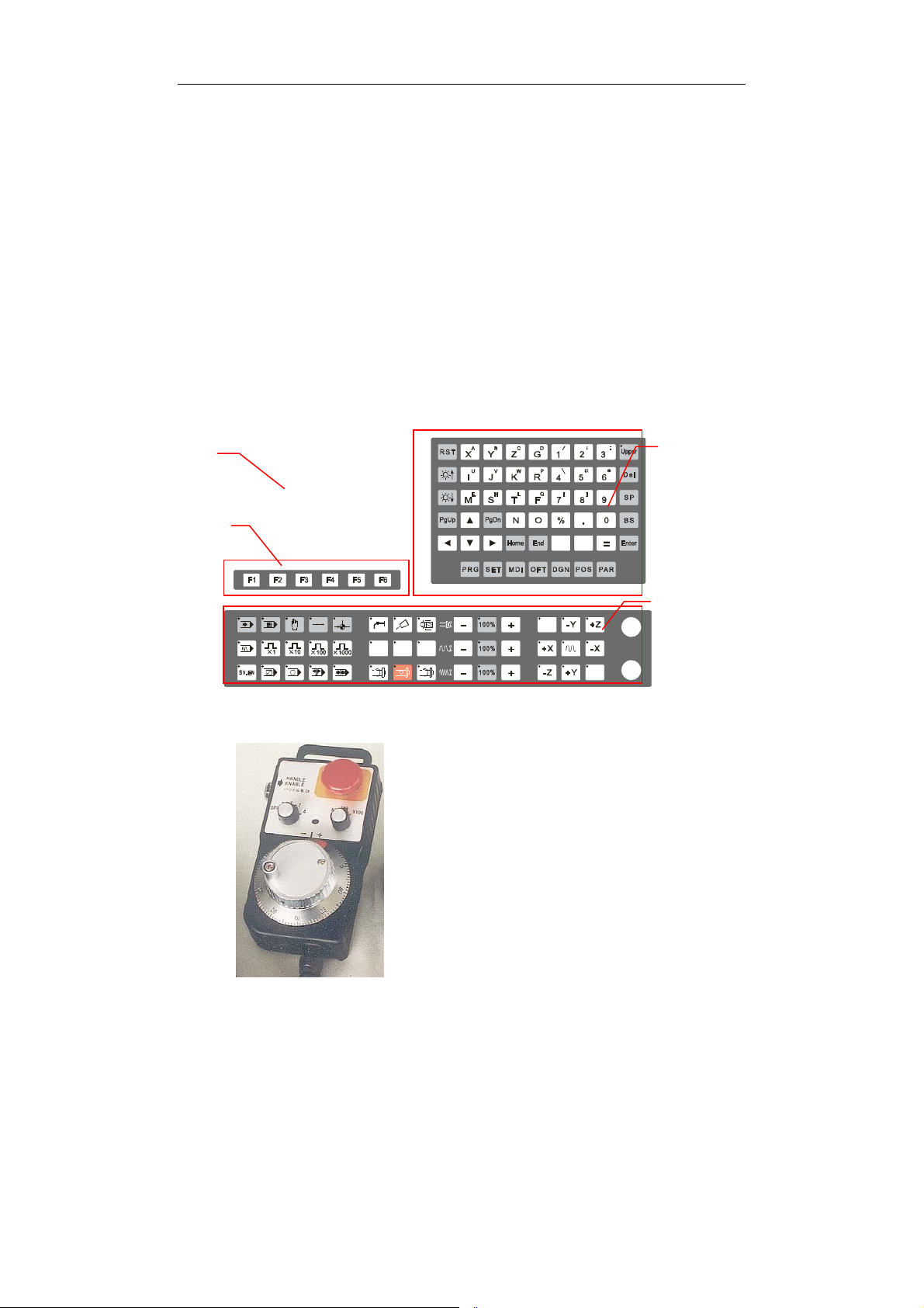
The user operates the mill either through the Numerical Control Unit
(NCU) or a Hand Pendant (optional). RS232 allows the user to
exchange data between the NCU and other computers. A PS/2
connector in the Data Exchange Port lets the user plug in a
keyboard.
LCD
Screen
Alpha
numeric
keyboard
Soft keys
-+
Machine
control
keys
Front face of Numerical Control Unit (NCU)
MPG(Manual pulse
generator) unit is a hand
pandent that compose of
an Emergency Stop
button, an axis switch
and a pulse generator. It
can be used for the user
to operate the machine at
a convenient place.
1

HNC-18/19T Operator’s Manual
There are four main areas on the front face of NCU: LCD Screen,
Soft keys, Alpha numeric keyboard and Machine Control keys.
These are shown in detail below.
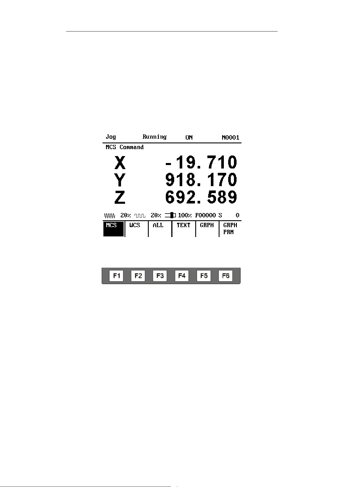
a) LCD Screen
The LCD screen in the upper right displays the machine’s status, the
tool’s position, the program’s content and other information.
b) Menu keys
Beneath the LCD screen are the “Soft keys” from F1 to F10. They
change their function depending on which menu is being used.
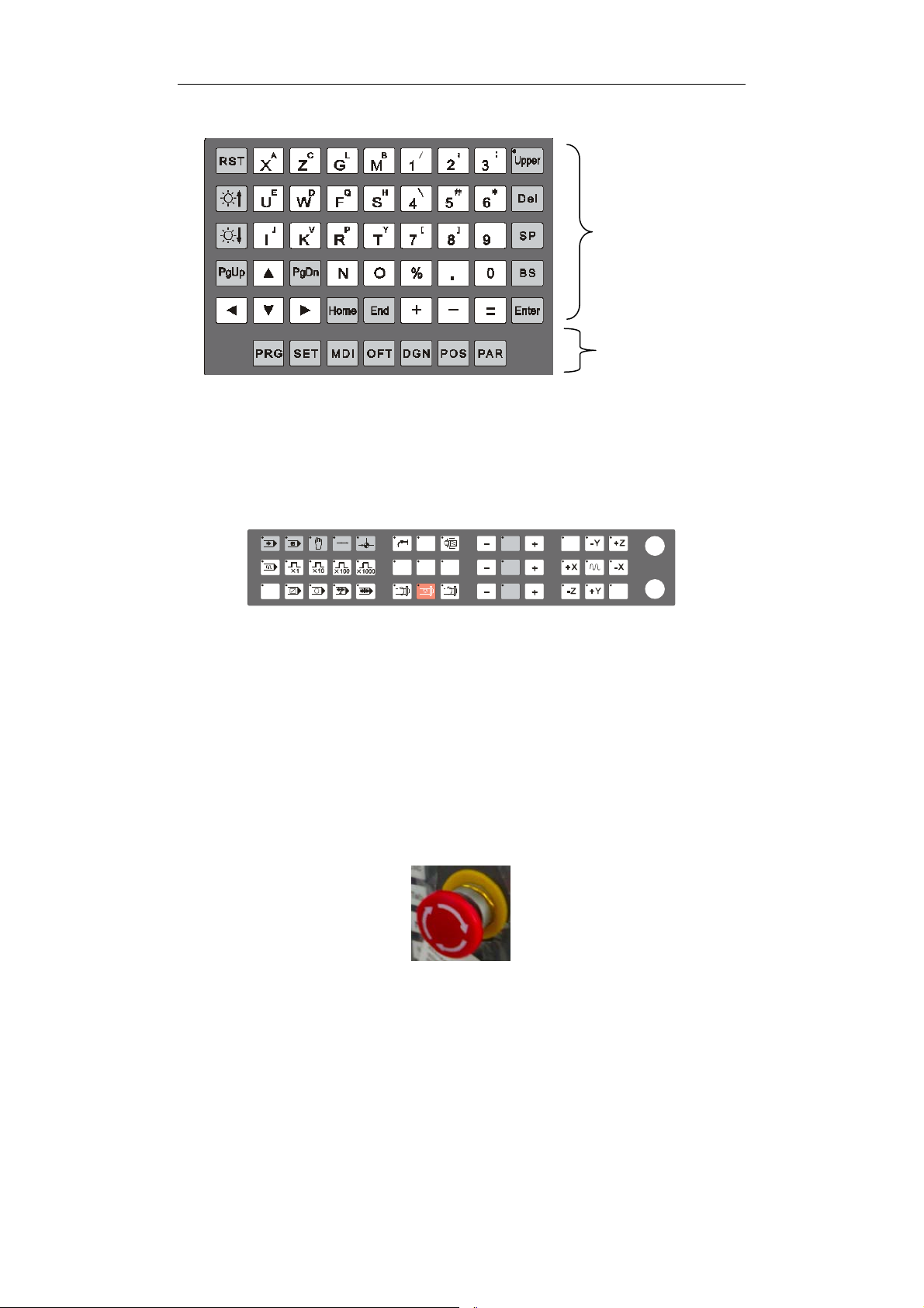
c) Alpha numeric keyboard
On the right side of the LCD screen is the Alphabetic keyboard.
These keys are used for editing a program, as well as changing or
viewing parameters.
1

HNC-18/19T Operator’s Manual
N
Alpha
umerical
keys
Function keys
d) Machine Control keys
At the bottom of the front panel are the Machine Control keys.
These keys operate the machine directly.
e) Other Controls
An emergency stop button is on the front panel to deal with abnormal
situations. Pushing down on the button stops the machine from any
further motion and sets the electronic brakes on the motor axes and
spindle. Pulling upon a stopped button resets the software system
and the machine can operate again under computer or manual
control
1


HNC-18/19T Operator’s Manual
A green “Cycle Run” button starts the automatic machining process.
A red “Feed Hold” button pauses machining under computer control.
1
1 Introduction
Machine Control Keys
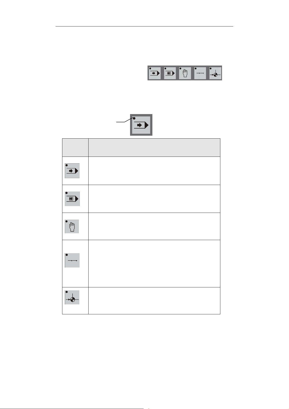
a) Mode Selection Switches.
To the right are shown the five
switches that select the operation
mode of the machine. Note that the small LED “activation” light on
the upper left of each key indicates in which mode the machine is
working.
KEY DESCRIPTION
Activation light
Automatic (AUTO) mode key: Pressing this key
switches to Auto mode. In AUTO mode,
workpiece can be machined automatically from a
program.
Single Block (SBL) mode key: Pressing this
key switches to “SBL” mode. In SBL mode, a
program can be run block by block.
Manual (MAN) mode key: Pressing this key
switches to manual operation or “jog” mode. In
manual mode, any axis of the tool can be
manually controlled.
Incremental (INC) mode key: Pressing this key
switches to “INC” operation mode. In INC
mode, the tool can be moved a number of steps
along any axis by either the Axis keys or the hand
wheel (Manual Pulse Generator). The number
of steps depends on which of the multiple-step
keys is selected.
Reference (REF) mode key: Pressing this key
switches to “Reference” mode. In Reference
mode, each motion axis can home exactly on its
reference position.
2
HNC-18/19T Operator’s Manual
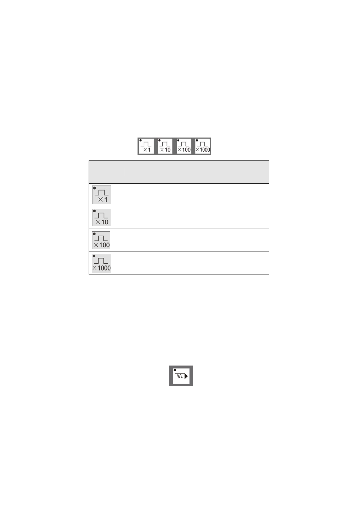
b) Multiple Step Keys:
Shown on the right are the four multiple step selection keys used
during incremental operation. Again, the LED light on the key’s
upper-left corner indicates the corresponding multiple selected.
First the INC key is pushed to set the Incremental Mode, then the
desired number of multiple steps is pressed and finally the desired
Axis key is pressed.
The multiple step selection keys are:
KEY DESCRIPTION
Each key push moves that axis one step
Each key push moves that axis 10 steps
Each key push moves that axis 100 steps
Each key push moves that axis 1000 steps
A step is equal to one micrometer (1 μm) for each linear axis (X, Y, Z)
and 0.001 degrees for each rotational axis.
On the same row as the Multiple Step keys, is the Verify key used in
conjunction with the Automatic Mode key. When the Verify key is
activated, a program runs at a higher speed than during normal
machining. The operator can run a program quickly be sure the
program performs the proper function.
3
1 Introduction
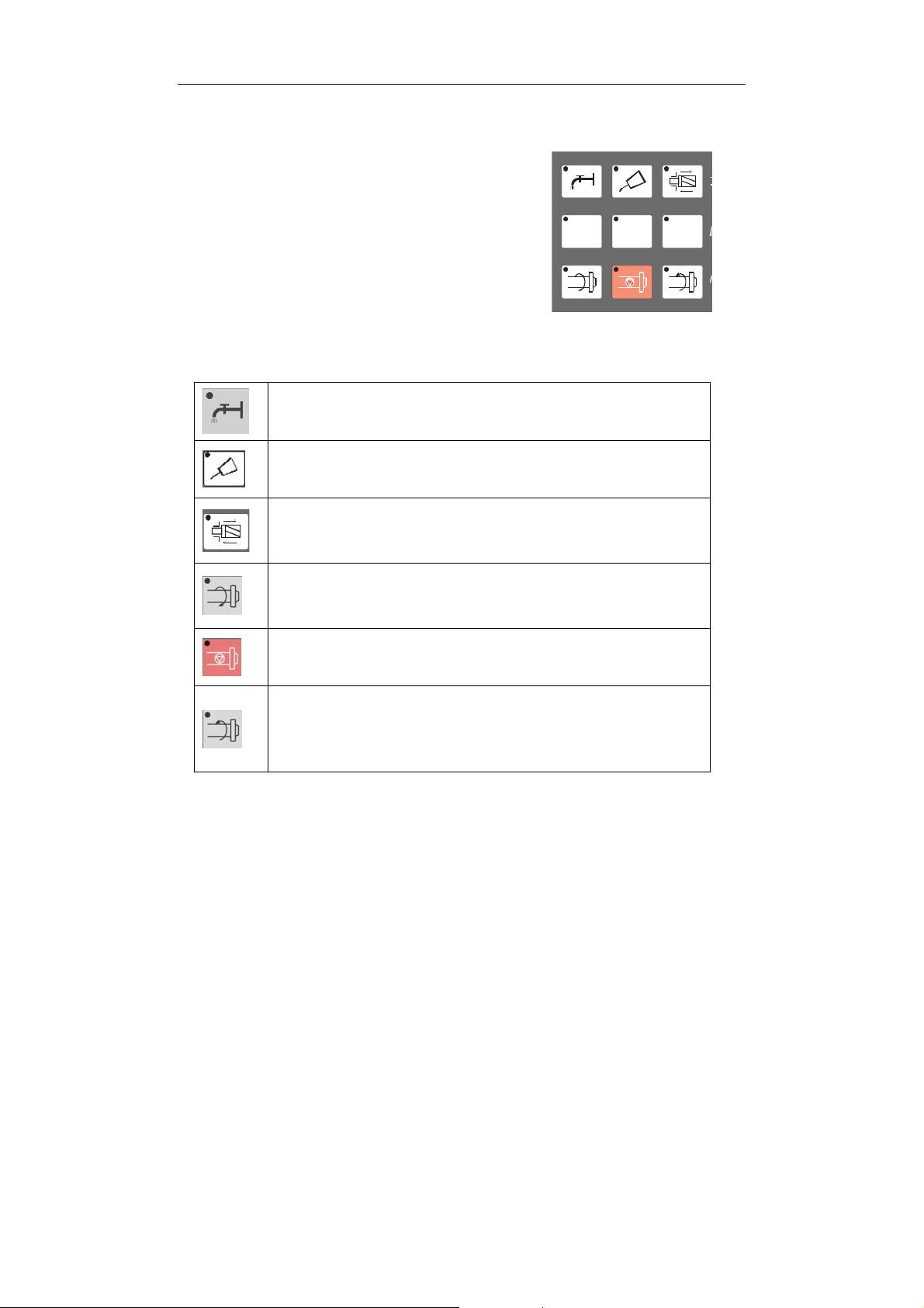
c) Spindle and Auxiliary Operation keys:
These nine keys usually function in Manual
mode. They control spindle, turret tool
selection, coolant and chuck functions.
These functions are activated only when no
program is running.
Details of the keys are shown below:
Coolant Switch key: This key opens or closes
the coolant flow
Lubrication key: Turn on the lubrication system
with this key.
Tool lock/unlock: After pressing this key, the tool
will be release if it is locked before and will be
locked if it is to be replaced in.
Spindle Clockwise Rotation key: Pressing this
key begins spindle rotation in the clockwise
direction (top of workpiece moves toward operator).
Spindle Stop key: Stop the spindle rotation by
pressing this key.
Spindle Counter-clockwise Rotation key:
Pressing this key begins spindle rotation in the
counter-clockwise direction (top of workpiece
moves away from operator).
4
HNC-18/19T Operator’s Manual
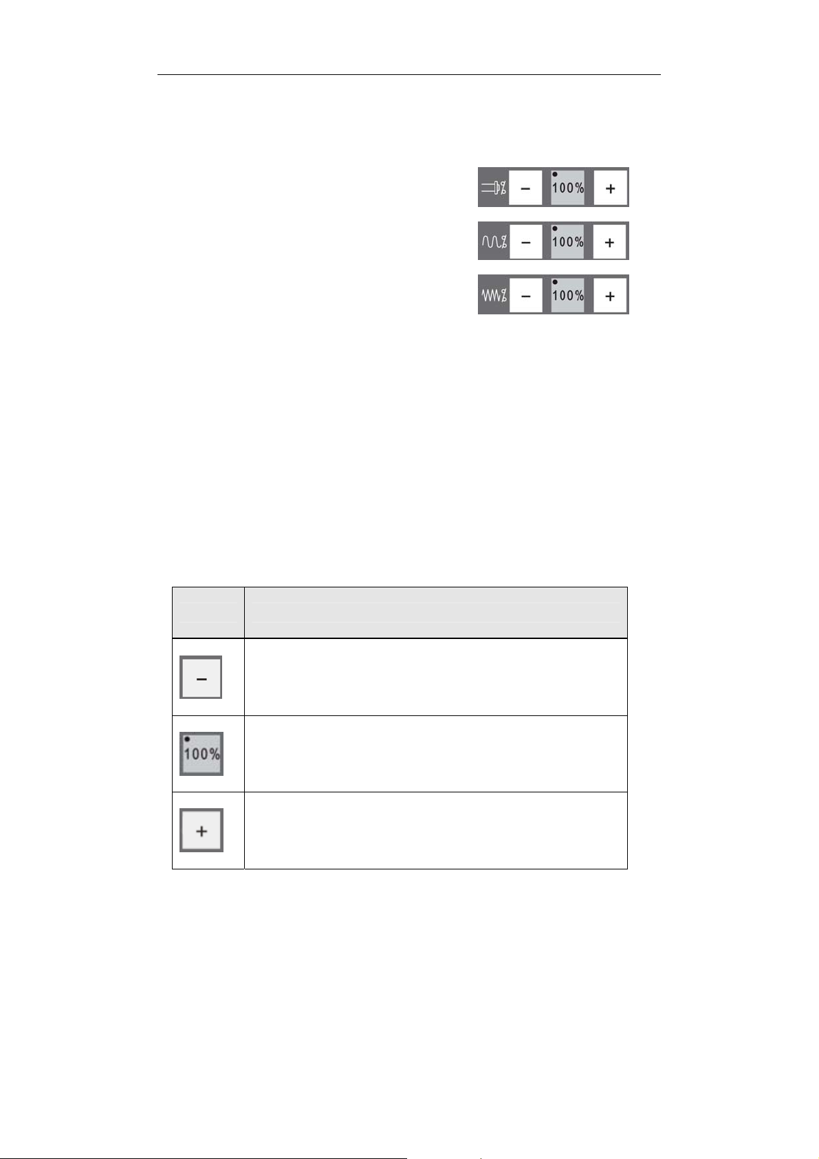
d) Speed Adjustment keys:
By pressing these keys the spindle speed,
rapid traverse rate and feed rate
(machining speed) can be adjusted. The
first row controls the spindle speed, the
second row controls the rapid traverse
speed and the bottom row controls feed
rate.
These keys work by adjusting the speed relative to a ”base” speed.
Different modes (Automatic, Single Block and Manual) may have
different base speeds. The base speed is set by the G-code
program or the parameter setting.
For each row, pressing the center key sets the speed at 100% of the
base speed; the LED light in the key’s upper-left corner is lit to signify
that the machine is running in base speed. Pressing the minus (-)
key, decreases the base speed by a fixed percent; pressing the plus
(+) key, increases the base speed by a fixed percent. Below is an
example where the speeds are changed by 2%:
KEY DESCRIPTION
Pressing this key decreases the speed 2% for
each press. The current speed or rate is displayed
on the LCD screen.
Once this key is pressed, the override ratio is set
to 100%. The LED light indicates that the current
speed is the base speed.
Pressing this key increases the speed 2% for each
press. The current speed or rate is displayed on
the LCD screen.
5
1 Introduction
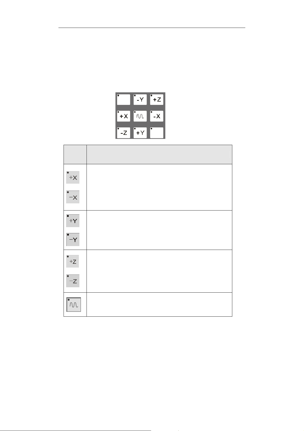
e) Axis Operation keys:
These five keys select 1) the desired axis and 2) the direction of
motion in various modes. These keys only function in Manual
Mode, INC Mode and Reference Mode. The LED light in the
upper-left corner specifies which axis or direction is selected.
KEY
DESCRIPTION
In INC mode or Manual Mode, the tool moves the X
axis in the positive direction while +X is pressed
and in the negative direction while –X is pressed.
In Reference mode, pressing the +X key homes the
X axis (finds the machine reference on the X axis).
In INC mode or Manual Mode, the tool moves the Y
axis in the positive direction while +Y is pressed
and in the negative direction while –Y is pressed.
In Reference mode, pressing the +Y key homes the
Y axis (finds the machine reference on the Y axis).
In INC mode or Manual Mode, the tool moves the Z
axis in the positive direction while +Z is pressed and
in the negative direction while –Z is pressed. In
Reference mode, pressing the +Z key homes the Z
axis (finds machine reference on the Z axis).
This key speeds up tool motion in Manual mode. It
must be pressed in conjunction with one of the Axis
keys.
6
HNC-18/19T Operator’s Manual
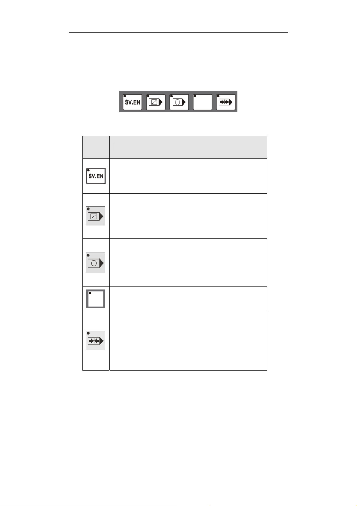
f) Other keys:
The five keys below are other keys that control various machining
functions.
KEY
DESCRIPTION
Servo enable key: Press this key to enable
or disable the servo.
Block Bypass key: Activating this key
bypasses program blocks that start with a “/”
character
Program Stop key: Activating this key
enables the M01 G-code stop function,
stopping the program at a desired block.
Not used.
Machine Lock key: Activating this key
prevents any motion from the spindle, the tool
changer turret or any axis; it is used for system
testing
7
1 Introduction
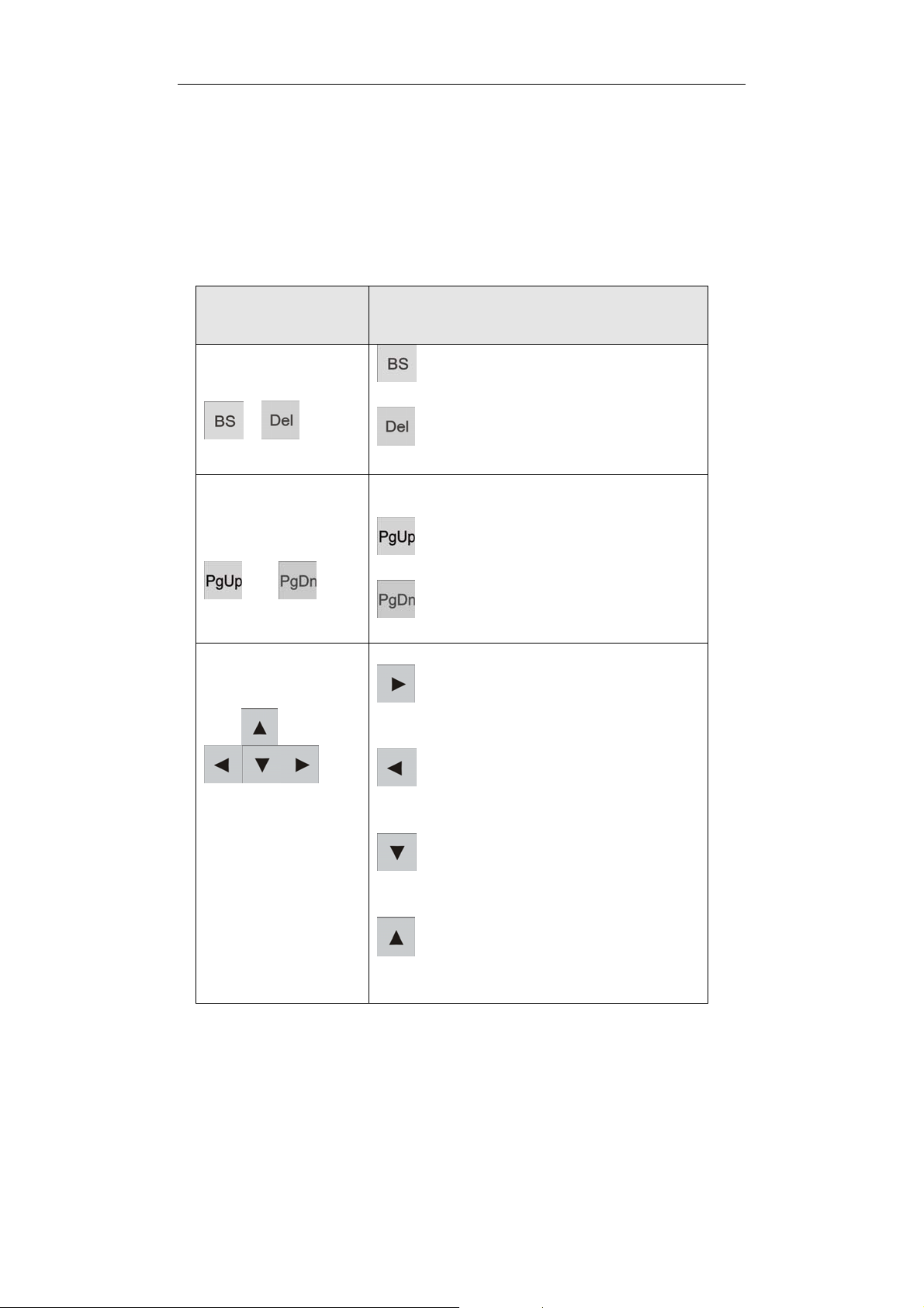
Alpha Numeric Keyboard
The Alpha Numeric keyboard lets the operator input either letters or
numbers for programs, parameters or conversational commands.
KEY
Delete keys
Page change keys
Cursor keys
DESCRIPTION
Backspace key deletes the
character in front of the cursor
Delete key deletes the character
at the cursor
There are two kinds of page change
keys:
PageUp key moves the page one
screen up
PageDown key moves the page
one screen down.
Right key: moves the cursor to
the right, selects a soft key to the right
or selects a column to the right.
Left key: moves the cursor to
the left, selects a soft key to the left or
selects a column to the left.
Down key: moves the cursor
down, selects a soft key on the bottom
or selects a row on the bottom.
Up key: moves the cursor up,
selects a soft key on the top or selects
a row on the top.
8
HNC-18/19T Operator’s Manual
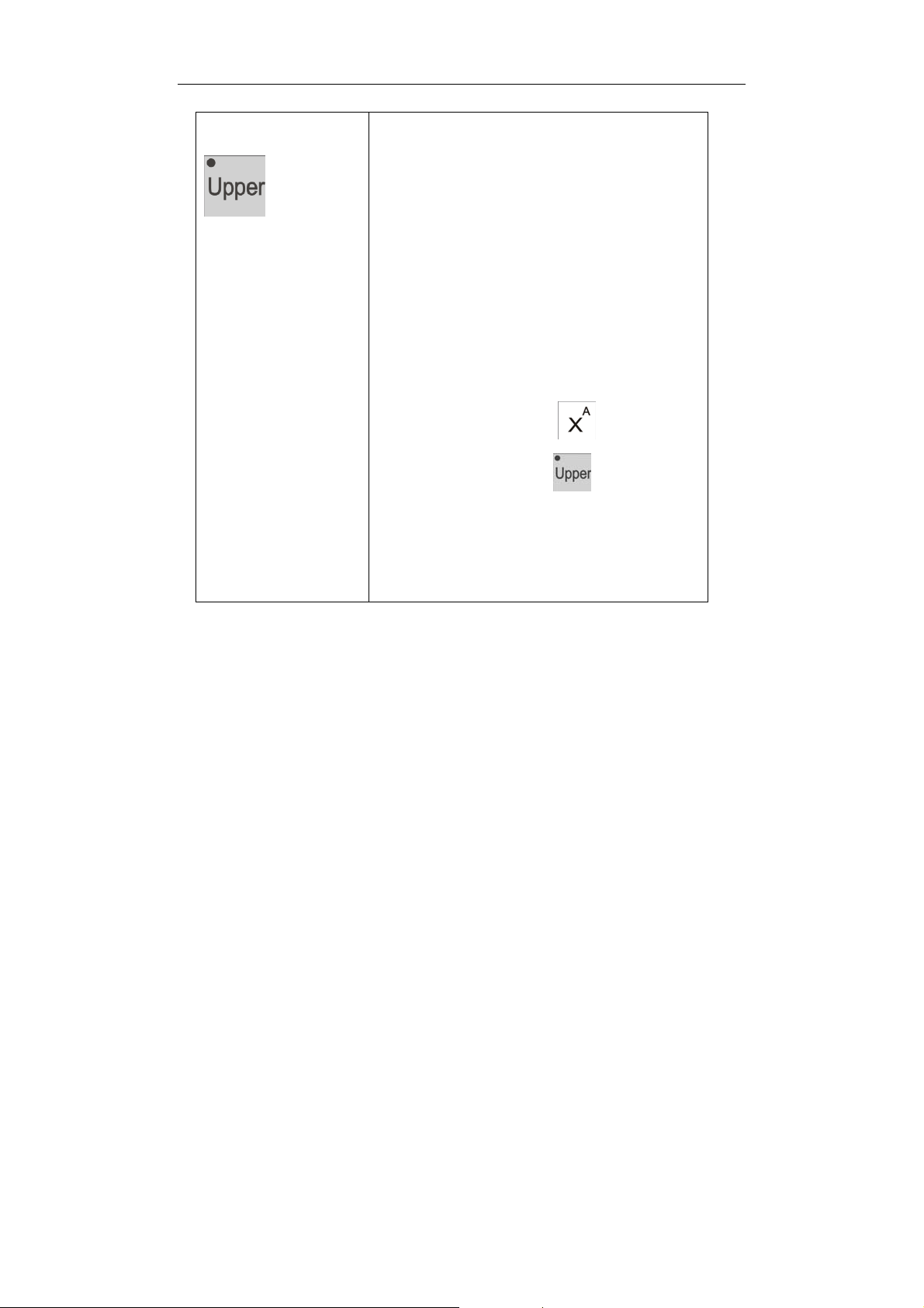
Shift Up key
The Shift Up key toggles the status of
double-character keys in the Alpha
Numeric keyboard. The LED light in the
upper-left corner indicates whether the
upper character is selected. When
the LED light is on, the upper character
is selected, otherwise the lower
character will be input. For example,
“X” will be input if is pressed
when LED light of
is off, while
“A” will be input when the LED light is
on.
9
1 Introduction
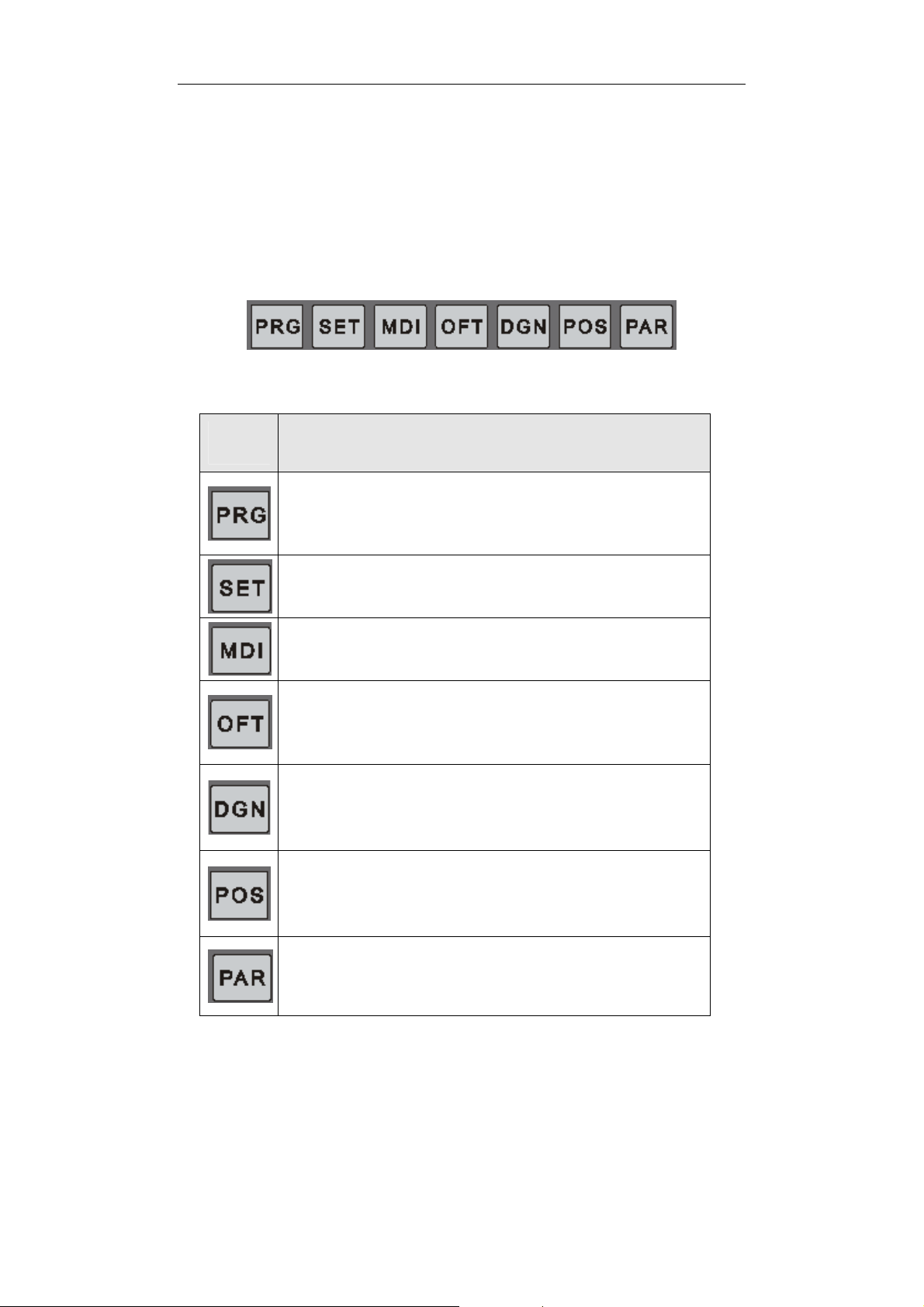
Menu tree
For HNC-18/19 CNC system, there are seven function keys below
the alpha numeric keyboard that bahave as seven different function
keys.
They are:
KEY
DESCRIPTION
PROGRAM submenu key: Press this key to do
operations related with program such as open, edit
or test a part program.
SETTING submenu key: Press this key to
activate setting submenu.
MDI submenu key: Press this key to switch to
MDI (Manual Data Input) submenu.
OFFSET submenu key: Press this key to enter
into OFFSET submenu which enable the operator
to set a tool’s offset data.
DIAGONOSIS submenu key: Activating this key
will present DIAGONOSIS submenus, which can
help user to tell what is the cause of faults
happened.
POSITION submenu key: This key will bring up
the POSITION submenus. Which allow the
operator to choose different axes coordinates type
to monitor.
PARAMETER submenu key: Press this key to
enter into PARMAETER submenu, where the user
can check or modify the system’s parameters.
10
HNC-18/19T Operator’s Manual
There are six soft keys to navigate each of the above key. The
functions of the soft keys change according to which function key is
active.
Each function is corresponding to one submenu. Let’s go through the
seven submenus one by one.
a) PROGRAM SUBMENU
OPEN (F1)
TST (F3)
REW (F4)
BP (F5)
DNC (F6)
EDIT (F2)
NEW (F3)
SAVE (F4)
PRG
TST (F3)
REW (F4)
BP (F5)
ROW (F5)
STOP (F6)
SAVE BP (F1)
LOAD BP (F2)
DNC (F6)
BACK (F6)
The key “PRG” has six submenus.
F1, corresponding to OPEN, picks which program is to be run or
edited. By default or switched from EDIT to OPEN, F3~F6 are
attached with TST, REW, BP and DNC.
TST, stands for PROGRAM TEST, verifies whether the opened
program has correct syntax and tool path.
REW, abreviation of REWIND, restarts a program from the first
block.
11

1 Introduction
Y
Y
BP, means breakpoint operation, has three submenus, SAVE
BP(Save the break point information to a file), LOAD BP(Load
the break point information from a file) and BACK(Back to OPEN
function menus).
DNC, enable the NC to receive program from a computer.
F2, corresponding to EDIT, allows the user to do edit operation and
some running process control operation. When EDIT is active,
F3~F6 are used for NEW, SAVE, ROW and STOP(Stop the program
from running)
NEW, creates a new program.
SAVE, saves the current program.
ROW, allows the user to run the program from a specified row
rather than from the first.
STOP, Stop the program from running.
b) SETTING SUBMENU
SET
WCS (F1) G54~G59, RCS(PgUp PgDw)
X RST (F4)
RCS (F2)
RST (F5)
Z RST (F6)
X HPI (F4)
HPI (F3)
HPI (F5)
Z HPI (F6)
The key “SET” has three submenus.
F1, WCS, workpiece coordinate system. Lets the user to set
coordinates system’s origin offset for G54 to G59 and RCS.
F2, RCS, relative coordinate system. This function has two
12

HNC-18/19T Operator’s Manual
A
submenus: X RST, resets the X position of RCS’s origin. Y RST,
resets the Y position of RCS’s origin. Z RST, resets the Z position of
RCS’s origin.
F3, corresponding to HPI(Home position input), also has three
submenus: X HPI, resets the X position of home point. Y HPI, resets
the Y position of home point. Z HPI, resets the Z position of home
point.
c) MDI SUBMENU
MDI
BAK.BP (F5)
LIGN TOOL (F6)
The key “MDI” has two submenus.
F5, corresponding to BAK BP, lets the tool go back to the break point
after an interactive intervention during automatic machining.
F6, corresponding to ALGN TOOL, allow operator to re-align the
tool’s dimension.
d) OFFSET SUBMENU
LEN Comp (F1)
OFT
DIAComp (F2)
The key “OFT” has two submenus.
F1, corresponding to Len Comp, allows the user to measure and set
the tool’s length compensation value.
13

1 Introduction
A
F2, corresponding to DIA Comp, used for the user to input the tool’s
diameter compensation value.
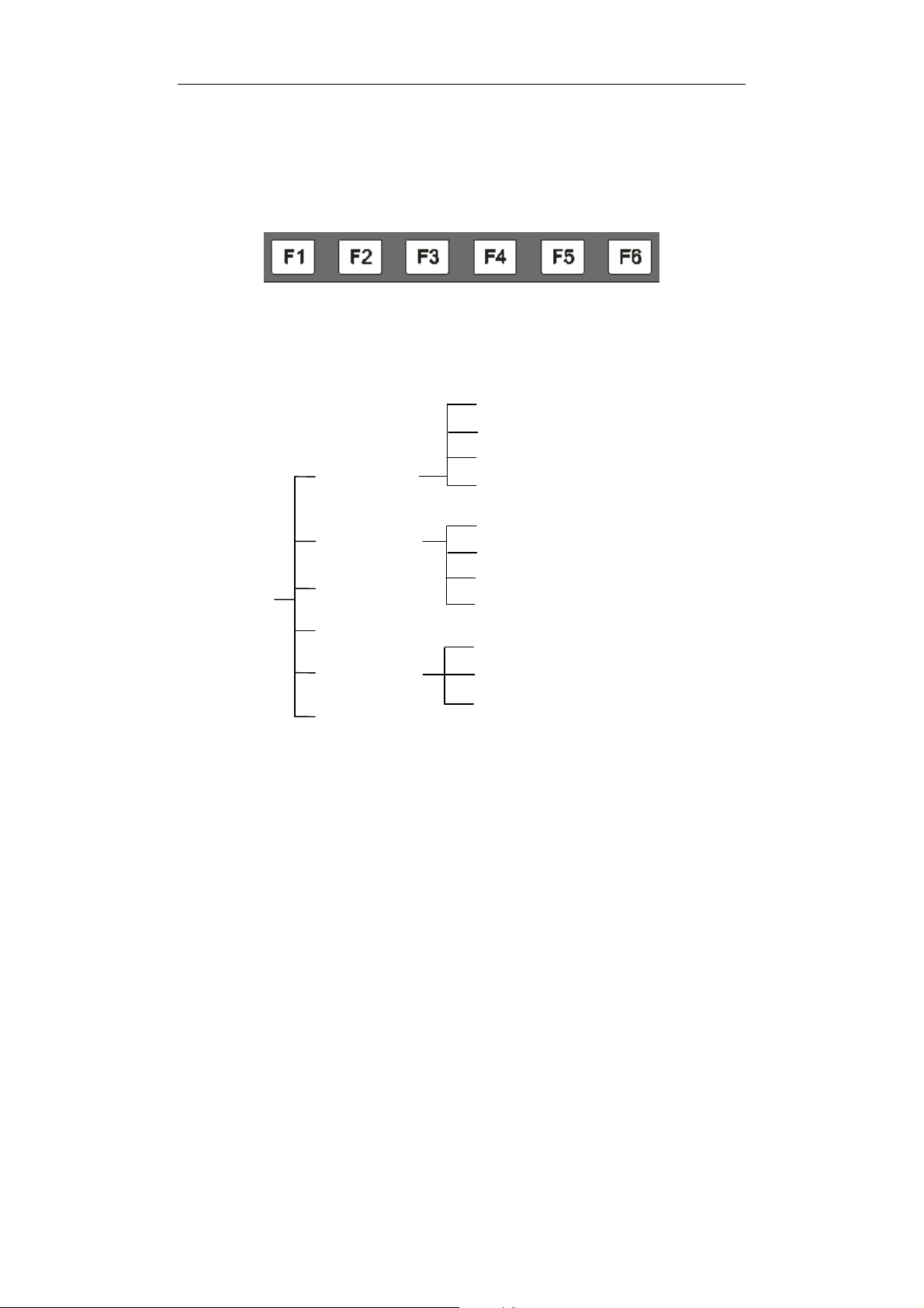
e) DIAGNOSIS SUBMENU
I/O (F1)
REG. (F2)
DGN MSG(F3)
BT(F5)
JOB NOTE (F6)
NEW JOB (F3)
RST JOB (F4)
BACK (F6)
The key “DGN” has five submenus.
F1, corresponding to IO, displays the status of I/O points.
F2, corresponding to REG, presents the value of the system
registers.
F3, corresponding to MSG, lists the contents of alarms.
F5, corresponding to ABT(ABOUT), presents version information of
the software.
F6, corresponding to JOB NOTE, is a statistic function which has
three submenus, NEW JOB, RST JOB and BACK.
NEW JOB, allows the user to set the planned workpieces
number.
RST JOB, lets the user to reset the statistic value.
BACK, back to the previous menu.
14

HNC-18/19T Operator’s Manual
A
f) POSITION SUBMENU
POS
MCS (F1)
WCS (F2)
LL (F3)
TEXT (F4)
GRPH (F5)
GRPH PARM (F6)
The key “POS” has six submenus.
F1, corresponding to MCS, displays machine coordinate system.
F2, corresponding to WCS, displays workpiece coordinates system.
F3, corresponding to ALL, displays overall information of the axes.
F4, corresponding to TEXT, displays the G code of the program.
F5, corresponding to GRPH, displays the graphical figure of the part.
F6, corresponding to GRPH PARM, allows the user to set graphical
figure’s parameters.
g) PARAMETER SUBMENU
BACK PARM (F1)
LOAD PARM (F2)
PAR
DNC PARM (F3)
PASSWORD (F4)
BACK PLC (F5)
LOAD PLC (F6)
15

1 Introduction
The key “PAR” has five submenus.
F1, corresponding to BACK PARM, makes a backup parameters.
F2, corresponding to LOAD PARM, loads a saved parameter file.
F3, DNC PARM, used to set the DNC parameters.
F4, PASSWORD, inputs the password to access the parameters.
F5, corresponding to BACK PLC, backs up the PLC program.
F6, corresponding to LOAD PLC, loads a saved PLC program.
16
 Loading...