

Page 1
EDU1AE/TOP Ver.1.1
EDU1AE/TOP/LTP Ver.1.1
Torque range : 0.4 – 15 Nm
U
Operator’s Handbook
IDENTIFICATION DATA OF THE MANUFACTURER
KOLVER S.r.l.
VIA MARCO CORNER, 19/21
36016 THIENE (VI) ITALIA
UIDENTIFICATION DATA OF THE PRODUCT
CONTROL UNIT MODEL: EDU 1AE/TOP – EDU1AE/TOP/LTP
CODE: 030000/TOP – 030000/TOP/LTP
YEAR OF CONSTRUCTION: 2009
UTECNICAL DATA OF THE PRODUCT
TRANSFORMER: 230V AC 50 Hz – 40 V DC 200 VA FUSE: 3,15 A
DIMENSIONS: 236x121x208 mm WEIGHT: 4.00 Kg
DECLARATION OF CONFORMITY
KOLVER S.r.l. declares that the new tool here described: Control unit model EDU 1AE is in conformity with the
following standards and other normative documents: 98/37/CE, 89/336/CE and 2006/95/CE, EN50144-1 and
EN60204-1.
It is also in conformity with RoHS and WEEE normatives.
Thiene, 01/01/09 KOLVER S.r.l
EDU1AE/TOP power supply and control unit is an innovative system for controlling the torque of our
PLUTO 3, PLUTO10 and PLUTO15 electric screwdrivers either inline, pistol or for automation.
Documentation Provided By HMC Electronics
33 Springdale Ave. Canton, MA 02021
http://www.hmcelectronics.com
(800) 482-4440
Page 2

EDU1AE/TOP and PLUTO deliver all the advantages of precision torque control electric tools at a fraction
of the price of transducerized tools.
The state-of-the-art electronic control circuit cuts the power supply to the motor calculating the correct
torque in response to 3 parameters; voltage, frequency and current, according to the selected options.
IMPORTANT: EDU1AE/TOP controller is a highly accurate unit but it is critically important to
select the correct options to ensure that proper torque is being applied. Read the menu description
carefully and in case you are unsure please contact Kolver for support information.
Here are a few advantages of EDU1AE/TOP:
• One controller only for a torque range from 2 to 15 Nm. For lower torque values, we offer the
EDU1AE/LTP/TOP.
• User interface screens: walk through a few simple steps to input the parameters requested for your
application and your fastening process can begin.
• 8 independent programs: with one PLUTO screwdriver you can replace 8 conventional
screwdrivers.
• Each program can accept the following settings: Torque, Speed, Type of Joint, Number of Screws
to be tightened, Number of Rejects allowed, Minimum screwing time, Maximum screwing time,
Ramp time, Auto reverse, Auto switch to the next program with any sequence, Allow or Prevent
reverse option.
• Password protected.
• Statistics menu with summary of work done: at the end of the day you'll know how many cycles
have been performed correctly, how many wrongly, total number of screws etc.
• 15 input and 11 output connectors: you can control all functions from PLC.
• Options include Socket tray or Switch box: maximum flexibility. USB port.
• Large 135 x 40mm blue display: easy to read from any angle.
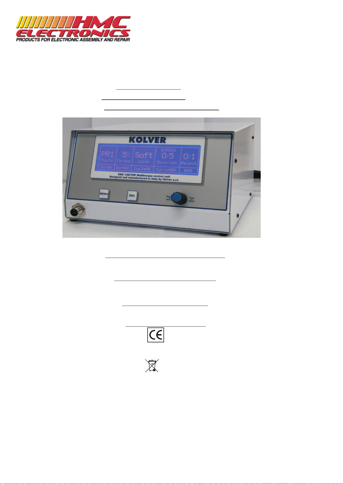
Turn the unit on through the on/off switch on the back panel. The unit will perform a general system check
then will show the first screen. Push MENU button for 1 second and display the main screen indicating the
Program (1 to 8), the Torque Level, the Joint type (Hard or Soft), the Screws Done and Set and the Rejected
Screws.
The five upper fields indicate the setting of the unit.
PR_ cycle: it indicates the Program you are in, it goes from 1 to 8 or EXT.
% Torque: it indicates the pre-set torque as a percentage.
Soft/Hard Joint: it indicates the pre-set joint.
Screws Done/Set: it indicates the screws done on the pre-set screws.
Reject: it indicates the rejected screws.
The five lower fields represent:
PR1
4%
Soft
0/5
0/1
Cycle
Torque
Joint
Done/Set
Reject
SCREWS
ScrOK
ScrNOK
CycleOK
CycleNOK
END
Documentation Provided By HMC Electronics
33 Springdale Ave. Canton, MA 02021
http://www.hmcelectronics.com
(800) 482-4440
Page 3
ScrOK Correct screwing done between min and max time.
ScrNOK Incorrect screwing done under min time or over max time.
CycleOK Cycle done well not exceeding the pre-set reject screws.
CycleNOK Incorrect cycle where in one or more screws the pre-set rejected screws have been gone over.
END End of cycle or of sequence.
MENU :
To enter the password and to move through the menu, use only the encoder knob in the front panel of the
unit: to move through the fields, just turn it; to enter a field to modify the value it must be pushed and turned
until you reach the desired value. To save the value, push it again.
To go back push ESC and to go out push ESC again.
Values are saved automatically moving through a screen to another or returning to the first screen.
PROGRAMMING THE UNIT
To enter the programmable menu push the MENU button for 5 seconds. At the first starting (and every time
after the unit has been switched off) the unit will ask for a password.
To enter/ modify the PASSWORD :
Push the MENU button for 5 secs. Push the encoder knob and enter the four numbers of the password
(default password is: 1111). Once entered the password, turn the encoder to ENTER, push it and the unit
will show the first screen.
To modify the password: digit the old password, enter CHANGE PWD, enter the new one and save it
pushing the encoder.
Once entered, to move through the 4 programming screens just push the MENU button. These screens are:
Setup Screwdriver, Setup Cycle, Setup Print and Statistics.
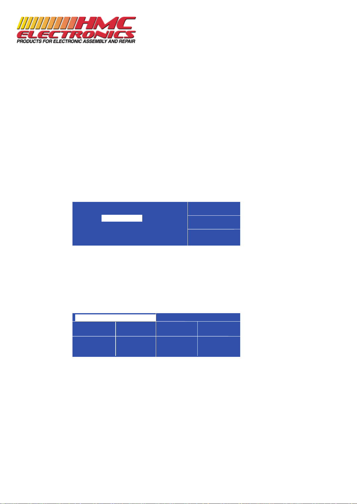
First screen:
Here you can modify the screwdriver parameters: Program nr., Screwdriver Model, Torque, Joint, Brake
Time (only HARD JOINT), Ramp Time, Speed and Reverse Time after the torque is reached.
To change any parameters: turn the encoder knob, select the parameter, push it in again. Turn the encoder to
change the value, push it in again thus saving the new value. The new settings have now been saved even if
the screen changes or ESC has been pushed. N.B. Only in this screen it is possible to select and set the
required program.
PR (Program): set from 1 to 8 individual programs. If you set EXT, Programs 1..8 will be selected externally
through the input connector, pins 8 thru 15, on the back panel.
MODEL
Pluto 10
SETUP SCREWDRIVER
TORQUE
4%
JOINT
Soft
BRAKE TM
OFF
RAMP TM
0,20
SPEED
600
REV TM
0,0
PR 1
PASSWORD:
ESCAPE
_ _ _ _
CHANGE PWD
ENTER
Done/Set
Documentation Provided By HMC Electronics
33 Springdale Ave. Canton, MA 02021
http://www.hmcelectronics.com
(800) 482-4440
Page 4

If you decide to work thru EXT Program, you need first to set all the parameters of programs 1...8 and then
select the EXT program; when working thru EXT program, no modification of programs 1..8 are possible.
Other parameters are the same as standard EDU1AE unit.
TORQUE: you can select the desired torque as a percentage of the torque range of the selected screwdriver.
For example, for a Pluto10, a 50% setting on hard joint will result in a torque in the area of 6 Nm.
Model Code Control unit
Torque (Nm) Speed
Output
Dimensions L
x ø mm
SOFT HARD Min Max
Pistol grip (PLUTO P)
PLUTO 3P 130204 EDU1AE/LTP 0,3-2 0,6-3 390 1200 Hex 1/4" 150x150x45
PLUTO 10 P/N 130210/N
EDU1AE/LTP 0,7-3,6 0,6-4,0 130 400
Hex 1/4" 150x150x45
EDU1AE 2-8 2-9,8 200 600
PLUTO 15 P/N 130215/N
EDU1AE/LTP 0,6-6,3 1,4-6,8 70 220
Hex 1/4" 150x150x45
EDU1AE 2-13,5 2-14,7 100 320
Pistol grip top connector (PLUTO P/U)
PLUTO 3P/U 130204/U EDU1AE/LTP 0,3-2 0,6-3 390 1200 Hex 1/4" 150x150x45
PLUTO 10 P/U/N 130210/U/N
EDU1AE/LTP 0,7-3,6 0,6-4,0 130 400
Hex 1/4" 150x150x45
EDU1AE 2-8 2-9,8 200 600
PLUTO 15P/U/N 130215/U/N
EDU1AE/LTP 0,6-6,3 1,4-6,8 70 220
Hex 1/4" 150x150x45
EDU1AE 2-13,5 2-14,7 100 320
In-line (PLUTO D)
PLUTO 3D 130203 EDU1AE/LTP 0,3-2 0,6-3 390 1200 Hex 1/4" 216x40
PLUTO 10 D/N 130211/N
EDU1AE/LTP 0,7-3,6 0,6-4,0 130 400
Hex 1/4" 216x40
EDU1AE 2-8 2-9,8 200 600
PLUTO 15 D/N 130216/N
EDU1AE/LTP 0,6-6,3 1,4-6,8 70 220
Hex 1/4" 216x40
EDU1AE 2-13,5 2-14,7 100 320
Automation (PLUTO CA)
PLUTO 3CA 130303 EDU1AE/LTP 0,3-2 0,6-3 390 1200 Hex 1/4" 164x40
PLUTO 10CA/N 130211/N
EDU1AE/LTP 0,7-3,6 0,6-4,0 130 400
Hex 1/4" 164x40
EDU1AE 2-8 2-9,8 200 600
PLUTO 15CA/N 133216/N
EDU1AE/LTP 0,6-6,3 1,4-6,8 70 220
Hex 1/4" 164x40
EDU1AE 2-13,5 2-14,7 100 320
PLUTO 20CA 130303 EDU1AE/20 2,5 20 43 130 Sq 3/8 '' 200x45,5
JOINT: You can select the type of joint (soft or hard) you are working on. A soft joint is typically a self
tapping screw on plastic or sheet metal, or a metric (machine) screw on a material subject to strain (for
example: gasket, o ring etc). A hard joint is typically a fastener joining metal with metal.
If you select the option SOFT the screwdriver will run the complete cycle at the selected speed.
If you select the option HARD the screwdriver will maintain the selected speed for a chosen time (brake
time) after the start and then the speed will be reduced automatically to apply a pre-torque before reaching
the final preset torque.
IMPORTANT: An incorrect selection of the joint type can result in inaccurate torque output.
BRAKE TIME: This option can be selected UonlyU in combination with the option HARD JOINT. You can
select a time between MIN (function excluded) and 10.0 seconds indicating how long the selected speed
(higher speed) will be on before switching to “pre-torque speed” (lower speed). The “pre-torque speed” will
be automatically chosen by the unit depending on the preset torque. The user cannot adjust the “pre-torque
speed”. CAUTION: The scope of the Brake Time is only to speed up the approach time in case of long
screws. Reaching the torque at higher speed will result in inaccurate torque output. To avoid inaccurate
torque we suggest selecting a shorter time, and then increase it step by step until finding the optimum time.
Documentation Provided By HMC Electronics
33 Springdale Ave. Canton, MA 02021
http://www.hmcelectronics.com
(800) 482-4440
Page 5

RAMP TIME: You can select the slow start time (acceleration) from 0.2 to 2 seconds. This option is mainly
used with self-tapping screws. Reaching the torque while the ramp is still on will result in inaccurate torque
output.
SPEED: You can select any speed value of the screwdriver between nominal (max) speed and 65% of max
speed .
N.B. The torque range is ensured only at the nominal speed of the screwdriver. Should you need to set lower
speeds, please check if the screwdriver stops correctly at the pre-set torque. In HARD JOINT the pre-set
speed only relates to the Brake Time; the second (slower) speed will be automatically chosen by the unit
depending on the preset torque.
REV TM: This option will automatically start a reverse cycle after a torque reached signal or a max TIME.
You can select a time between 0 (function excluded) and up to 10 seconds. During the reverse cycle, it is
necessary to keep the start lever pressed (or the start contact closed) otherwise the screwdriver will stop
before the pre-set time.
To progress to the second screen, push MENU again.
Second screen: SETUP CYCLE
You can modify the cycle parameters: Number of screws, Rejected screws, Min and Max Screwing Time,
Unscrewing, New program contact, Free cycle or Sequence.
SCREWS: number of screws in each Program, from 1 to 99.
REJECT: number of rejected screws allowed in each single cycle. Screws which result in NOK (Not OK -
see below) may or may not be repeated if it has been set as rejected or zero. You can set up to 9 rejected
screws.
If the number of rejected screws exceeded, the main screen changes with OVER and the screwdriver stops.
To start again, push ESC or RESET contact.
If OVER appears during a sequence, there are 2 possibilities:
RESET SINGLE CYCLE > push ESC or close the RESET contact for 1 sec.
RESET SEQUENCE > push ESC or close the RESET contact for 5 secs. until the beginning of a new cycle.
N.B. These functions exist only in OVER situation. During the normal use of TOP unit, the ESC function
does not work. Instead the RESET contact works only during a single cyle and not during a complete
sequence. See also RESET on SIGNALS I/O.
SCREWS OVER
PR 4% Soft 0/5 1/1
Cycle Torque Joint Done/set Reject
ScrOK ScrNOK CycleOK CycleNOK END
SCREWS
3
REJECTS
2
MIN TIME
0.3
MAX TIME
2.5
UNSCREW
YES
NEW PR
NO
PR CYCLE
FREE
PR 1
SEQUENCE
_________
SETUP CYCLE
Documentation Provided By HMC Electronics
33 Springdale Ave. Canton, MA 02021
http://www.hmcelectronics.com
(800) 482-4440
Page 6

MIN TIME: time between the lever pressed and the torque reached. If torque is reached before the
minimum time set, an error signal is sent, and the screw is identified as a NOK screw. This happens typically
when operator tightens the same screw twice.
MAX TIME: time between the lever pressed and the maximum acceptable rundown time. No torque signal
is generated. After max. time is reached, an error signal is sent, identified as a NOK screw. This identifies
possible stripped screws.
UNSCREW: In this field if you select YES the reverse function of your screwdriver is active, i.e. you can
unscrew as usual whenever you wish. If you select NO the reverse function of your screwdriver is not active
(you can never unscrew). If you select NOK the reverse function of your screwdriver will be active only after
a NOK screw signal (you can unscrew if you wish so after NOK screw).
NEW PR: if YES, at the end of the Program cycle you must close the contact New Cycle (pin #4) to
continue.
If NO, signal will stay on until the start of the screwdriver for the next cycle.
PR CYCLE: In this field you have the choice between free and fixed sequence of programs. This parameter
is valid for all 8 programs and the modification of 1 of them affects all of the Programs.
The PR CYCLE and SEQUENCE boxes are linked: the Sequence Program Numbers appear only if you
select FIXED (see below).
PR CYCLE SEQUENCE
_ _ _ _ _ _ _ _
PR CYCLE
FIXED
SEQUENCE
2 3 6 _ _ _ _ _
If you select FREE, you can choose the program you need: manually and/or externally (EXT).
If you want to change the program manually go to the SETUP SCREWDRIVER screen and select PR 1..8
If you want to change the program externally go to the SETUP SCREWDRIVER screen and select PR EXT,
back to the main screen you will see:
EXT
PR ?
Cycle
You will see the number of the selected Program only after the choice through pins 8...15 of the input
connector (through switchbox or PLC).
If you select FIXED, the second field (SEQUENCE) appears with a series of 8 squares where you can set
the sequence you want.
Example:
2 3 6 _ _ _ _ _ automatically cycle 2, then 3, then 6 and back to 2 again.
1 3 8 1 5 _ _ _ automatically cycle 1, then 3, then 8, then 1, then 5, and back to 1 again.
If you select FIXED with PR EXT, the program to choose will be forced. On the screen you will see for
example:
EXT
PR 2
Cycle
The number of the program due will flash until you choose it.
Documentation Provided By HMC Electronics
33 Springdale Ave. Canton, MA 02021
http://www.hmcelectronics.com
(800) 482-4440
Page 7

The program continues with the cycle sequence you have chosen, with the END signal lit at the end of the
sequence.
To progress to the third screen, push MENU again.
Third screen: SETUP PRINT
Available only with USB port option.
You can set date and hour.
PRINTED CYCLE: different description for each cycle, max 15 letters. It will be printed after each screw.
PRINTED DESCRIPTION: This is the description of max 50 letters on the main screen. It can be printed
only on request after specific input (pin 7) or at the beginning of each cycle (if this option has been allowed).
The TOP unit with USB port allows to save each cycle data.
It's just necessary to insert the key in the USB port, after a short bip, you can proceed.
In the key, a new folder will be created: EDU1AE_T. In it, there will be another folder called like the date
set in the unit (year-month-day). In this folder, every day you could save each cycle done in .txt file.
Example:
11/03/09 09:43 PR1 P15 S 20% 320RPM 01/03 OK_ ____ Program 1
11/03/09 09:43 PR1 P15 S 20% 320RPM 02/03 OK_ ____ Program 1
11/03/09 09:43 PR1 P15 S 20% 320RPM 02/03 NOK TMIN Program 1
11/03/09 09:43 PR1 P15 S 20% 320RPM 03/03 OK_ END_ Program 1
11/03/09 09:43 PR1 P15 S 20% 320RPM 00/03 NOK TMAX Program 1
11/03/09 09:43 PR1 P15 S 20% 320RPM 01/03 OK_ ____ Program 1
11/03/09 09:43 PR1 P15 S 20% 320RPM 02/03 OK_ ____ Program 1
11/03/09 09:43 PR1 P15 S 20% 320RPM 03/03 OK_ END_ Program 1
Date (day/month/year),
Hour (hh:mm)
Program number (PR1),
Model (in this example P15 means Pluto 15)
Joint (S = soft – H = hard)
Torque,
Speed (RPM)
Done/total Screws
Result (OK-NOK)
Error description and END (TMIN if the error is of the min time, TMAX if max time, END when cycle is
ended)
15 letters description.
N.B. All firmware versions support BOMS devices formatted in FAT12, FAT16 or FAT32 file systems only
where the sector size is 512 bytes. No other file systems or sector sizes are allowed.Furthermore, only
BOMS devices which support the SCSI or AT command sets are supported.On devices which implement
multiple LUNs, only the primary LUN (0) is supported. The VNC1L firmware can only access the primary
partition of a disk.
SCREWS
DATE
12/01/2000
PR 1
SETUP PRINT
TIME
01:15
PRINTED CYCLE
Program 1
PRINTED Made in Italy by Kolver s.r.l.
DESCRIPTION
Documentation Provided By HMC Electronics
33 Springdale Ave. Canton, MA 02021
http://www.hmcelectronics.com
(800) 482-4440
Page 8

To export and display these data in an Excel file: capture these data in an Excel sheet. Then re-select them,
select DATA, TEXT TO COLUMNS, FIXED WIDTH, push twice CONTINUE, set the Done/Total Screws
column as text. Now each single data has its own cell: this allows to make any statistics.
(In OpenOffice, when coping, the file asks how to display the data: just set space.)
N.B. If in the 15 letters description you set several spaces, in the Excel file you will create as many columns
as these spaces.
To progress to the fourth screen, push MENU again.
Fourth screen: STATISTICS
Here you can see the statistics of each single program.
SCREW OK: Total number of correct screws done between MIN and MAX TIME. Torque signal: ok.
SCREWS NOK: Total number of not OK screws, which have fallen outside the set time parameters.
CYCLE OK: Total number of correctly completed cycles in each pre-set Program.
CYCLE NOK: Total number of cycles where the quantity of the rejected screws is higher than the preset
number of rejected screws.
T. SCREWS: Total number of screws for each cycle.
T. CYCLES: Total number of done cycles.
TOTAL: Total number of screws done from the installation of the program (no possible reset).
RESET: if you set YES, all the statistics of the program you are in will reset.
BIP SOUNDS
Bip sounds at the end of fastening of each screw help check if the operation is correct or not. When the
torque has been reached meeting all the parameters set, a SINGLE OK signal (see below) and a 1 sec bip
sound are generated . Each time you push a button or you move through the screens, the unit utters a 0,5 sec
bip sound.
Torque reached under min time, during the Ramp time or under the Brake time (only HARD JOINT) will
result in a SINGLE NOK signal (see below) and three x 1 sec bip sound.
SIGNALS I/O
INPUT
Input signals: contact to earth common pin 1 (COM 0vdc):
PIN2 > START Contact between pin 1 and 2. Clockwise.
PIN3 > REVERSE Contact between pin 1 and 3. Counterclockwise.
PIN4 > NEW CYCLE Used only if NEW PR is set on YES; contact between pin 1 and 4 to start a
new cycle.
PIN5 > STOP MOTOR Contact between pin 1 and 5; it stops the
motor in any situation. On the screen, you’ll see STOP MOTOR.
PIN6 > RESET CYCLE Contact between pin 1 and 6; it resets any partial values of the cycle you are
working in. See also special functions in case of REJECT.
PIN7 > PRINT LABEL Contact between pin 1 and 7: it prints on
request the 50 letters label (see PRINT DESCRIPTIONS, SETUP PRINT).
4%
Soft
0/5
0/1
SCREW OK
0
SCREW NOK
2
CYCLE OK
0
CYCLE NOK
0
T.SCREWS
0
T.CYCLE
0
TOTAL
0
PR 1
RESET
NO
STATISTICS
Documentation Provided By HMC Electronics
33 Springdale Ave. Canton, MA 02021
http://www.hmcelectronics.com
(800) 482-4440
Page 9

PIN8 > PR1
PIN9 > PR2
PIN10 > PR3 Contact between pin 1 and 8-15, to choose the desired programs (possible
only with EXT program)
PIN11 > PR4
PIN12 > PR5
PIN13 > PR6
PIN14 > PR7
PIN15 > PR8
PIN 16 > 24 Vdc 24 Vdc protection for switchbox and socket tray (max 250mA available).
N.B. This output can be used but the protection treshold of 250mA must be
valid for all the outputs. If exceeded, on the first screen, you’ll see
PROTECTION ACTIVATED PLEASE RESET. It is necessary to switch
off the unit for 5-6 seconds.
OUTPUT
PNP output 24Vdc signals.
Earth: pin 1.
PIN1 > COM 0VDC Common earth for all Outputs.
PIN2 > SINGLE OK Correct screwing done between min and max time.
Signal starts when the screwing is done and it resets when the lever is
pressed to start a new one.
PIN3 > SINGLE NOK Incorrect screwing done under min time or over max time. Signal starts at
the end of the screwing and it resets when the lever is pressed to start a new
one.
PIN4 > CYCLE OK Cycle done well not exceeding the pre-set reject screws. Signal starts at the
end of the cycle and it resets a new one starts.
PIN5 > CYCLE NOK Incorrect cycle where in one or more screws the pre-set rejected screws have
been gone over. Signal starts at the end of the cycle and it resets a new one
starts.
PIN6 > TOTAL END End of cycle or of sequence. Signal starts at the end of the cycle and it resets
a new one starts.
PIN7 > LEVER Signal starts when the lever is pressed or at input start and it stops when it is
released.
PIN8 > MOTOR ON Signal starts when the motor starts and it switches off when the motor stops.
PIN9 > STOP TIME Signal starts when the screwing exceeds the max time (see also MAX
TIME). This option is useful to a NOK screw which has reached the torque
under min time or over the max time. It’s also useful when a PLUTO tool is
used with a stop time and not after the torque reached. Signal starts when the
unscrewing is done and it resets when the lever is pressed to start a new
screwing.
PIN10 > REV TIME Signal starts if REV TM is on when the unscrewing cycle is over. Signal
ends when the lever is pressed for a new cycle.
PIN 11 > FAILURE Signal starts at any error detected by the unit (see Trouble Shooting).
PIN 12 > NOT USED Not Used.
N.B. TO RESET ERRORS, TURN OFF THEN SWITCH ON THE UNIT. RESET OF ERRORS #6 AND #8
COMES AUTOMATICALLY AFTER THE PROBLEM END.
IF THE PROBLEM PERSISTS, PLEASE CONTACT YOUR NEAREST KOLVER DEALER.
Documentation Provided By HMC Electronics
33 Springdale Ave. Canton, MA 02021
http://www.hmcelectronics.com
(800) 482-4440
Page 10

ESPLOSO
Ref. Description Quantity Code
1 Main board TOP - Main board TOP/LTP 1 852421/T - 852421/TL
2 Connector F TOP 16 pin 1 800112
3 Connector F TOP 12 pin 1 800110
4 Connector 12 pin TOP 1 800111
5 Connector 16 pin TOP 1 800113
6 Display board TOP - Display board TOP/LTP 1 852422/T - 852422/TL
7 Knob TOP 1 800040
8 Spacer 20mm Di 3 De6 5 872436/T
9 Bottom 1 812012/T
10 Board seat TOP 2 872442
11 Back panel 1 812014/T
12 Transformer 200VA 230V - Transformer 200VA 110V 1 848009 - 848009/110
13 Cover 1 812013/T
14 ISO 7380 - M3 x 6 --- 6N 25 872443
15 812012-T-1 Cover for USB port 1 812012/T
16 Connector 220V filtered 1 800718
17 USB Board 1 852423
18 Rubber 2 see 12
19 Plate 1 see 12
20 ISO 4762 M5 x 40 --- 22N 1 872430/N
21 Connector of screwdriver 1
201666/T
22 Hexagon Nut ISO – 8675 - M12 x 1 - N 1
23 Membrane 1 872445/T
24 Hexagon Nut ISO – 4036 - M3 - N 6 800056
25 Knob cover 1 800040
26 Support 4 800016
27 Fuse 2 800619
Documentation Provided By HMC Electronics
33 Springdale Ave. Canton, MA 02021
http://www.hmcelectronics.com
(800) 482-4440
 Loading...