

Page 1
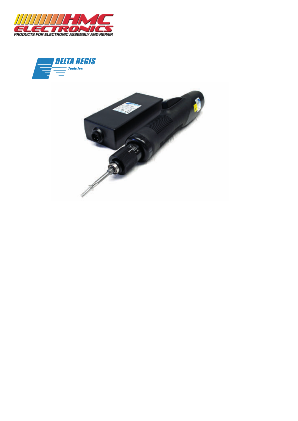
32VDC ESL600 Series Brushless Screwdrivers & Controllers
Operation Manual
CAUTION - Please read, understand, and follow all operating and safety instructions in
this manual before using the Tools and Controllers.
The 32VDC 600 Series tools are designed for exclusive use with specic Delta Regis
controllers as dened in this manual. Do not attempt to use the tools and/or controllers in
with any products other than as specied in this manual.
Doc. 32V_Brushless_Series_Manual_R2
Copyright © 2011 Delta Regis Tools, Inc
Documentation Provided By HMC Electronics
33 Springdale Ave. Canton, MA 02021
http://www.hmcelectronics.com
(800) 482-4440
Page 2

ESL600 Series
Operation Manual
Important - Installation and Safety
Please read and understand the operation manual and follow all safety and operation instructions.1.
Use these products in a suitable dry, indoor location. Do not use the tools and controllers in damp, 2.
wet or high temperature environments. Do not use in the presence of ammable liquids or gases.
Ensure that the controller has proper ventilation. Do not expose the tools and controllers to areas 3.
subject to airborne contaminants (eg. dust, metal lings).
Use only a properly grounded electrical outlet of the correct supply voltage to power the screwdriver 4.
co ntroller. Ensure that the supply outlet is overload protected and of sufcient amperage capacity.
Use only the correct plug for the controller and outlet. Hold the plug of the power cord when 5.
connecting or disconnecting. Do not pull on the cable.
Do not expose the cable, tool or controller to oil, chemicals, or heat. Ensure that the cable is routed 6.
and used in such a manner as to not be subject to sharp objects that may abrade or cut the cable.
Locate the controller in a suitable, safe location on a steady surface. Do not place in a high location 7.
where there may be a risk of it falling. Secure the controller in position to prevent possible movement
caused by pulling on the power or tool cables.
Do not cover the controller or stack any objects on top of or near the controller. Ensure that adequate 8.
clearance and ventilation is provided around the perimeter of the controller.
The ‘BECT6’ series controllers are for use exclusively with Delta Regis brand ‘ESL6’ series 9.
screwdrivers as specied on the following pages. Use of the controller (or screwdriver) with any
other screwdriver (or controller) may result in malfunction, damage, or injury.
In the event that the controller is overloaded beyond the maximum current rating, an internal fuse will 10.
disrupt power. Should the controller stop functioning, or exhibit abnormal or intermittent operation,
please discontinue use immediately and send the controller to an authorized service centre for
troubleshooting and repair.
Excessive duty cycle will cause the tool and/or controller to overheat. If this occurs, discontinue use 11.
until cooled down and reduce cycle rate. As a general rule, do not exceed 10-15 screws/minute.
The ‘ESL6’ series screwdrivers incorporate a protection circuit which stops the electric screwdriver 12.
if the tool is switched from forward to reverse while running. Should this happen, the operator must
release the tool trigger and restart the fastening cycle.
Turn the main power switch off when the controller is not being used. Unplug the controller if it is not 13.
being used on a regular basis.
Do not attempt to disassemble or repair the screwdriver or controller. Repairs should only be 14.
performed by qualied technicians properly trained in the safe operation, troubleshooting, and repair
of these devices. Please consult Delta Regis for the location of the nearest service depot.
Use only the factory specied Delta Regis brand replacement parts and accessories with these tools 15.
and controllers.
Any damage to the tool and/or controller resulting from misuse, abuse, or failure to follow these 16.
guidelines will void the limited product warranty.
Warning - Failure to understand and follow proper installation guidelines, safety requirements,
and operating instructions may result in malfunction, component damage, property damage,
shock hazard, re hazard, injury or death.
Grounding - This controller (and AC power cord) is equipped with a 3-prong electrical receptacle/plug
with ground pin. The controller must be connected to a properly grounded AC electrical outlet. Do not
attempt to use this controller without a properly functioning ground connection. Never connect a live
circuit to the ground pin or internal yellow-green ground wire.
Page 2
Documentation Provided By HMC Electronics
33 Springdale Ave. Canton, MA 02021
http://www.hmcelectronics.com
(800) 482-4440
Page 3

ESL600 Series
Operation Manual
Adjusting Torque
Page 3
Insert the power plug into a receptacle and set the FWD/REV switch to the “F” position.1.
Apply the bit to the screw head and press the lever or push the tool downward, the start switch will be 2.
turned ON and the motor will start running.
Once the screw has tightened and reached the torque you had set, the tool will shutoff automatically.3.
To reset the tool, release the lever or release the bit from the screw head.4.
To remove the screw, set the FWD/REV switch to the “R” position.5.
Determine the torque output of the tool by checking a tightened 1.
fastener with a torque wrench.
Increase or decrease the torque by rotating the Torque Adjustment 2.
Ring.
Rotating the Ring clockwise increases torque output.3.
Rotating the Ring counterclockwise decreases torque output.4.
Check the adjustment with a torque wrench. 5. A number of factors
will affect torque output from one application to another. Final
torque adjustment should be made on the application through a of
series of gradual increases. Always start below the desired torque
and work upward.
Remove the housing nut from the electric screwdriver after setting 6.
the desired torque and attach the torque locking sleeve. This will
help avoid accidental torque adjustment.
Note: The numbers on the torque scale are for reference only and do
not indicate actual torque value.
Inserting / Removing Bits
Push the bit retainer inwards and it will release. The bit can now be inserted or removed.
Operation
Proper Grip
To prevent damage to your investment, it is essential that all users have a proper
and secure grip on the screwdriver at all times. As shown, the user has a rm grip
on the screwdriver with the FWD/REV switch easily reached with the thumb and
the start lever with the index nger.
Note: A rm grip is required to prevent the tool from spinning and possibly
damaging the unit.
Documentation Provided By HMC Electronics
33 Springdale Ave. Canton, MA 02021
http://www.hmcelectronics.com
(800) 482-4440
Page 4

ESL600 Series
Operation Manual
Specifications
Page 4
600 Series
Model Number
(1)
Start
Type
Range
(In.Lbs)
Range
(Nm)
Speed
(RPM) Hi
Speed
(RPM) Lo
Screwdriver
Bit Type
Length
(mm)
Diameter
(mm)
Weight
(g)
(C)ESL610-ESD Lever 0.2 - 3.1 0.02 - 0.35 1000 700 4mm 185 32 385
(C)ESL611-ESD Lever 0.4 - 6.2 0.05 - 0.69 1000 700 4mm 185 32 385
(C)ESL612-ESD Lever 0.9 - 8.7 0.10 - 0.98 1000 700 4mm 185 32 385
(C)ESL623-ESD Lever 1.3 - 10.5 0.15 - 1.18 1000 650 1/4” hex 245 36 520
(C)ESL623F-ESD
(2)
Lever 1.3 - 10.5 0.15 - 1.18 2000 --- 1/4” hex 245 36 520
(C)ESL623P-ESD Push 1.3 - 10.5 0.15 - 1.18 1000 650 1/4” hex 245 36 520
(C)ESL623PF-ESD
(2)
Push 1.3 - 10.5 0.15 - 1.18 2000 --- 1/4” hex 245 36 520
(C)ESL624-ESD Lever 2.6 - 16.5 0.29 - 1.86 1000 650 1/4” hex 245 36 520
(C)ESL624P-ESD Push 2.6 - 16.5 0.29 - 1.86 1000 650 1/4” hex 245 36 520
32VDC Brushless Power Controller
Model Number Outlets Speeds
Tool
Connector Output Input
Dimensions
L x W x H (mm)
Weight
(g)
BECT620 1 Hi/Lo 4 pin 32/20V DC 100-240VAC, 50/60 Hz, 1.2A 145 x 60 x 35 250
BECT620I 1 Hi/Lo 4 pin 32/24V DC 100-240VAC, 50/60 Hz, 1.2A 195 x 76 x 56 450
BECT620C 1 Hi/Lo 6 pin 32/20V DC 100-240VAC, 50/60 Hz, 1.2A 145 x 60 x 35 250
BECT620IC 1 Hi/Lo 6 pin 32/24V DC 100-240VAC, 50/60 Hz, 1.2A 195 x 76 x 56 450
The BECT620 and BECT620I Controllers are designed specically to run our 32V Brushless Screwdrivers. These
compact, lightweight controllers accepts input voltages of 100-240VAC, 50/60Hz (1.2A). Output voltage to the
driver is 32VDC on the high speed setting and 24 or 20VDC on low speed. CE/RoHS/ETL Approved.
• Precise Torque Control, Low Torque Reaction.
• Quiet, Brushless DC motor means no carbon dust.
• Compact body design results in exceptional
manouverability and operator comfort.
• Less heat build-up and higher duty cycle capabilities than
conventional brush motors. 3 year motor warranty.
• Brushless design results in low maintenance.
• 32VDC Screwdrivers feature ESD safe housings.
• CE, RoHS Compliant.
Power supply shipped with standard North American cordset. For EU cord, add sux ‘E’ ; for UK cord add sux ‘UK’ to part number.
32VDC Brushless Screwdrivers
(1)
Screwdriver models with a ‘C’ prex have a 6-pin cable connector for use with BECT620C and BECT620IC controllers, or for use with
the BECT626-SSO Counting Controller. Refer to BECT626-SSO manual for counting controller operation and use.
(2)
For fast screwdriver models ESL623F-ESD and ESL623PF-ESD, use controller model BECT620I (4 pin controller).
For fast screwdriver models CESL623F-ESD and CESL623PF-ESD, use controller model BECT620IC (6 pin controller).
Documentation Provided By HMC Electronics
33 Springdale Ave. Canton, MA 02021
http://www.hmcelectronics.com
(800) 482-4440
Page 5
The ‘BECT6’ Series Controllers are not user serviceable. Any repairs must be performed by a Delta Regis
authorized service center. Please consult Delta Regis Tools for further information and the location of the
nearest authorized service center.
Repairs to ‘ESL6’ series screwdrivers must be performed by trained personnel, knowledgeable and
qualied in the repair of DC electric screwdrivers. Use only genuine Delta Regis parts when servicing
these products.
Do not attempt to modify the tools or controllers.
Service
The ESL600 Series Tools and Controllers are warranted for one year from the date of purchase against
defects in material and workmanship. In addition, the brushless motor in the ESL600 Series Screwdrivers is warranted for three years from the date of purchase against defects in material and workmanship.
This warranty does not cover damage due to transportation, abuse, misuse, or improper service. Our sole
remedy is to repair or replace (at our discretion) any unit found to be defective due to defects in material
or workmanship. It is the responsibility of the user to return any product thought to be defective, freight
prepaid, to our warehouse for inspection and evaluation.
There is no warranty of merchantability or tness of purpose. In no event will Delta Regis Tools, Inc.
be liable for business interruptions, loss of prots, harm, injury, damage, personal injury, cost of delay,
or any other special, indirect, incidental, or consequential losses, costs, or damages.
Warranty
Page 5
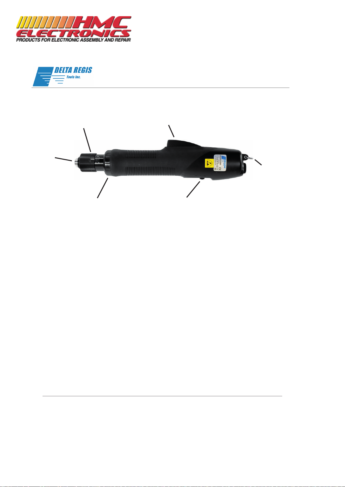
Torque Adjusting Nut
Turn to adjust torque. Higher values on scale
indicate higher torque. Numbers on the scale
are for reference only and are not a torque
indication.are not a torque indication.
Bit Holder
Retract sleeve to
insert/remove bits.
Housing Nut
Remove housing nut to
install torque locking sleeve.
Trigger
Suspension Ring
Use to suspend the tool.
Forward/Reverse Switch
Three position switch with center position
being OFF. The OFF position is recommended
when changing bits.
ESL600 Series
Operation Manual
Documentation Provided By HMC Electronics
33 Springdale Ave. Canton, MA 02021
http://www.hmcelectronics.com
(800) 482-4440
 Loading...