

Page 1

ŀ
Page 1
ASG-CT2500
ASG-SD2500 Series Screwdriver Controller
User’s Guide
Version 2.0.0
June, 2012
Documentation Provided By HMC Electronics
33 Springdale Ave. Canton, MA 02021
http://www.hmcelectronics.com
(800) 482-4440
Page 2

Page 2
ASG Precision Fastening ASG-CT2500 User’s Guide
Version 2.0.0
Major Revision: June, 2012
Firmware Revisions
GUI: Firmware Version 2.1.1.0
Controller: Firmware Version C-6.11.0
To download the latest version of this manual visit:
www.asgprecisionfastening.com
ASG Precision Fastening
(888) 486-6163
15700 S. Waterloo Rd.
Cleveland, OH 44110
USA
© 2012 Jergens Inc.
All Rights Reserved
Documentation Provided By HMC Electronics
33 Springdale Ave. Canton, MA 02021
http://www.hmcelectronics.com
(800) 482-4440
Page 3

Page 3
Table of Contents
Safety Precautions…………………………………………………………………………..………………………………………………….5
Introduction……………………………………………………………………………………………..…………………………………………6
Installation………………………………………………………………………………………………………….…..………………….……..7
Run Tool Screen………………………………………………………………………………………………………………………………….9
Tool Information Screen
Setup Screen……………………………………………………………………………………………………………………………….…….12
Tool Triggering
Bolt Counts
Bolt Retries
Reverse Settings
Parameter Setup
Prevailing Torque
Bolt Sequences
Task Menu……………………………………………………………………………………………………………….……………...…….18
Renaming and Importing Tasks
Exporting Tasks
Input Programming…………………………………………………………………………………………………….……………...…….20
Task Select.
Enable Bolts.
Remote Start.
Reverse Select.
Remote Reset.
Remote Halt.
Output Programming………………………………………………………………………………………………..……………..……….25
Documentation Provided By HMC Electronics
33 Springdale Ave. Canton, MA 02021
http://www.hmcelectronics.com
(800) 482-4440
Page 4

Page 4
Input/Output Port Pin Guide………………………………………………………………….…………………………………………27
Graph Screens…………………………………………………………………………………..………………………………………………29
Graph Data Export
Data Screen……………………………………………………………………………………………………………………………………32
Erasing Data
Downloading Data
System Setup Screen…………………………………………………………………………………………………………..…………35
Passwords
Date/Time Settings
Tool Trigger Sensitivity
Tool Calibration
Controller Information
Firmware Updates
Touch Screen Calibration
LCD Brightness Adjustment
Service & Warranty………………………………………………………………………………………….…………………………….40
Documentation Provided By HMC Electronics
33 Springdale Ave. Canton, MA 02021
http://www.hmcelectronics.com
(800) 482-4440
Page 5
Safety Precautions
Be sure to read all instructions and precautions contained in this manual, failu
result in personal injury and/or damage to tooling and components.
Do not operate or plug in the controller/system with wet hands or in wet environments.
Failure to observe this may result in injury due to electric shock.
Ensure the cont
roller is properly plugged in to a grounded electrical receptacle. Do not remove
the ground pin or use any adapter plugs.
Always shut down the controller when changing cables or tools. Failure to do so could damage
the tool or controller.
Keep w
ork area clear of clutter and distractions that may cause the operator to lose control of
the tool or the components.
Tool cable must be properly routed and festooned to avoid tangling and trip hazards.
Always use safety glasses when using electrical
Do not use any part of the system (tool, cable, or controller) for anything other than its
specified application. Use of the system or its components for unintended applications could result in
injury to the operator, failure of the sy
Never modify or disassemble any component of the system. Modification or disassembly of the
system could result in injury and void the warranty.
Page 5
assembly tools.
stem, and could void the warranty.
re to do so may
Documentation Provided By HMC Electronics
33 Springdale Ave. Canton, MA 02021
http://www.hmcelectronics.com
(800) 482-4440
Page 6
Page 6
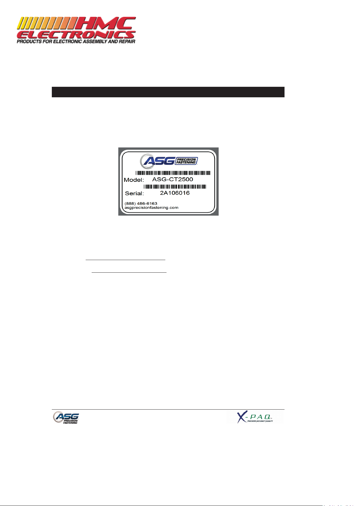
Introduction
Thank you for investing in a ASG-CT2500 Controller from ASG Precision Fastening! This user’s guide will
assist you with setting up your controller.
Please start by finding the serial number label on the bottom of the controller.
Take note of the serial number and record it below with your date of purchase. This information will be
necessary should any service be required in the future.
Serial Number: :
Date of Purchase: :
Documentation Provided By HMC Electronics
33 Springdale Ave. Canton, MA 02021
http://www.hmcelectronics.com
(800) 482-4440
Page 7
Page 7
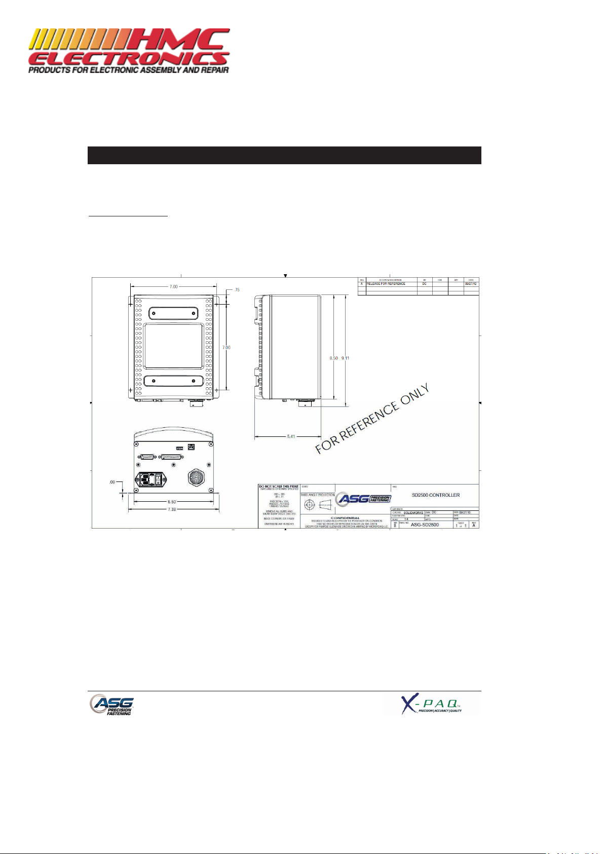
Installation
Installation of the ASG-CT2500 is very straightforward. Follow these steps to connect your system for
the first time:
Controller Mounting:
The ASG-CT2500 comes standard with a mounting plate for attaching to the wall, workbench, or tool
stand. Secure the controller using the (4) provided holes in the mounting plate. These provided holes
are meant for #6 screws, but can be enlarged to suit user’s needs.
Ensure the controller power cord can reach a properly grounded receptacle without creating a trip
hazard in the work area. The controller should also be mounted within view of the operator, and should
be accessible and within reach for programming and modification.
Documentation Provided By HMC Electronics
33 Springdale Ave. Canton, MA 02021
http://www.hmcelectronics.com
(800) 482-4440
Page 8
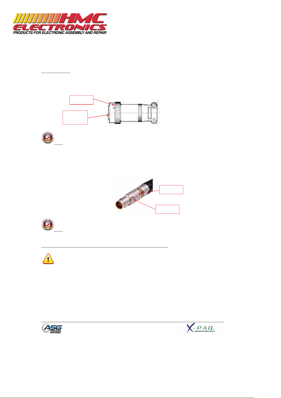
Tool Installation:
Connect the tool cable to the connector on the bottom of the controller by
tabs in the large cable connector. Align these tabs and insert the cable to the cont
twist-
lock on the cable connector clockwise until it
Note
: To remove the cable from the controller, rotate the twist
counter-
clockwise until it pops free, and then remove the cable
Obtain the ASG-
SD2500 tool and identify the slot on the screwdriver connector into which the
screwdriver cable plugs. Find the red dot on the small end of the cable, and align it to the slot in the
screwdriver connector. Insert the
cable to the tool firmly until it
Note
: To remove the cable from the tool, slide the grip of the cable connector away from the
tool, then pull the cable out of the tool.
Connect the controller to the power source and power
Do not depress either the push to start spindle or the throttle lever during controller power
doing so will result in a ToolEE Error which will require a reboot of the controller.
Twist-lock
Alignment
Tabs
Page 8
identifying
roller, then rotate the
clicks into place.
-
lock on the cable connector
from the controller.
clicks into place.
-up the controller.
Grip
Dot
the alignment
-up,
Documentation Provided By HMC Electronics
33 Springdale Ave. Canton, MA 02021
http://www.hmcelectronics.com
(800) 482-4440
Page 9
Page 9
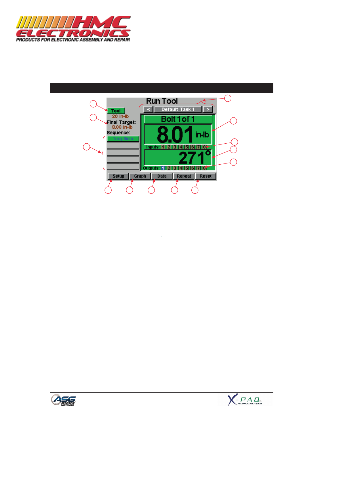
Run Tool Screen
1. Task Selection: Shows the user the current task, and allows the user to select one of 12
available tasks. Selecting the button with the task name will bring up
the Task Menu where another task may be selected or altered. The
arrow keys will advance to the previous or next task. Settings for bolt
counts, parameters, inputs, outputs, etc will switch with these actions
to the settings of the selected task.
2. Tool Information Button: Displays the Tool Information screen that shows tool characteristics.
3. Final Target: Displays the target value of the active Parameter, either torque or
angle.
4. Torque Reading: Displays the torque seen by the tool during or at the end of the
fastening cycle. This field will color code at the end of a fastening cycle
to denote Pass (green), Fail – High (red), or Fail – Low (yellow) as
defined by high and low limits of the selected Parameter.
5. Angle Reading: Displays the angle seen by the tool during or at the end of the fastening
cycle. This field will color code at the end of a fastening cycle to denote
Pass (green), Fail – High (red), or Fail – Low (yellow) as defined by high
and low limits of the selected Parameter. The field remains unhighlighted when Angle Monitoring is disabled within the Parameter.
6. Inputs: Displays (1) radio button for each of the (8) available inputs. The
appropriate radio button will illuminate blue when the input is active.
1
2
3
4
5
13
7
8 9 10 11 12
6
Documentation Provided By HMC Electronics
33 Springdale Ave. Canton, MA 02021
http://www.hmcelectronics.com
(800) 482-4440
Page 10

Page 10
7. Bolt Sequence Steps: Displays the sequence step and selected parameter. The parameter
name will be highlighted red, yellow, or green at the end of its cycle to
show its status.
8. Setup Button: Takes you to screens where you may set up Tasks, Parameters, Bolt
Sequences, Inputs, Outputs, and System Settings.
9. Graph Button: Displays the most recent fastening cycle graphically as Torque vs. Time,
Angle vs. Time, Torque vs. Angle, Speed vs. Time, and Power vs. Time.
10. Data Button: Displays a table that contains rundown characteristics for the last 100
fastening cycles. Additional data is available in the internal memory and
can be downloaded to a USB flash drive from this screen as well.
11. Repeat Button: Depressing this button keeps the controller on the current bolt in a
batch. The bolt sequence will not advance to the next bolt until the
button is released.
12. Reset Button: Depressing this button resets the fastening bolt count in the event of a
failure, retry lockout, user request. The reset button also resets any
outputs. This button can be disabled when the controller is locked with
a password.
13. Outputs: Displays (1) radio button for each of the (8) available outputs. The
appropriate radio button will illuminate blue when the output is active.
Documentation Provided By HMC Electronics
33 Springdale Ave. Canton, MA 02021
http://www.hmcelectronics.com
(800) 482-4440
Page 11
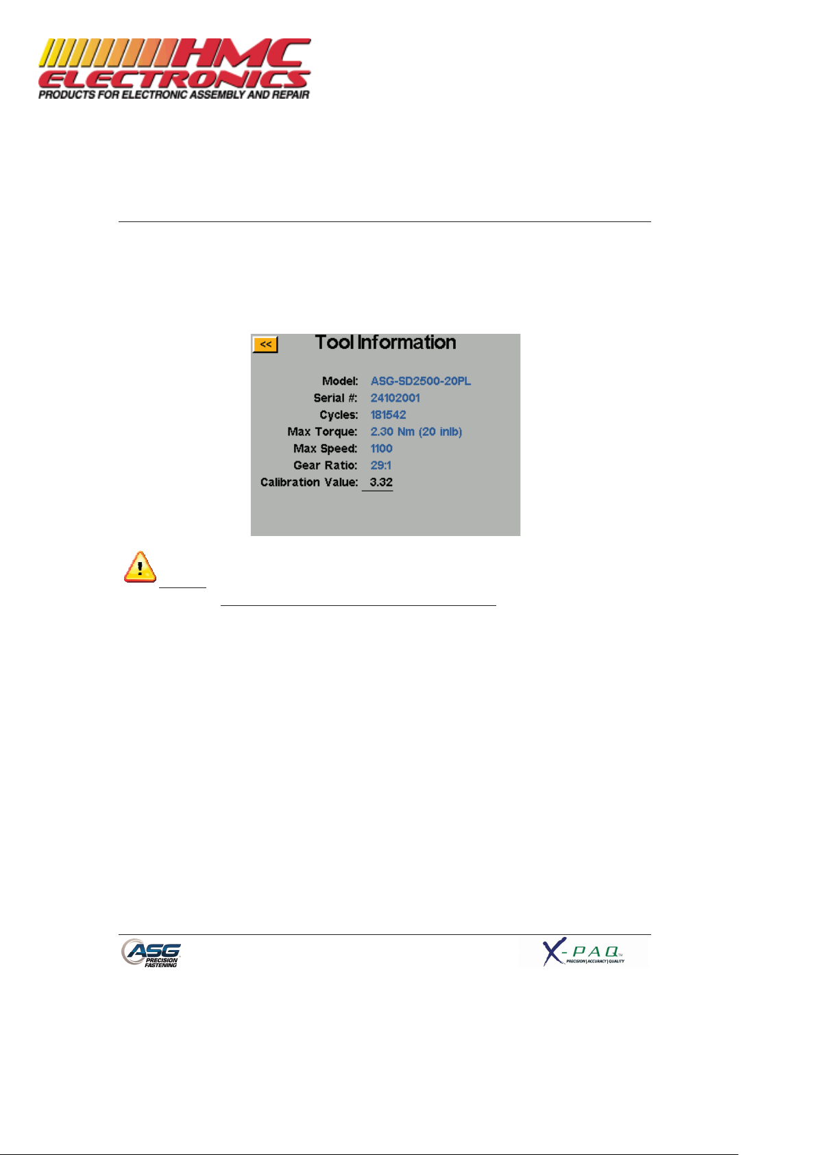
Tool Information Screen
This screen displays characteristics of the tool that is atta
• Model Number
• Serial Number
•
Number of Cycles on the Tool
• Max Torque
CAUTION
: Tapping on the Calibration Value will take you to a screen where the value can be
manually changed.
This screen is for qualified calibration technicians only.
calibration value of the tool could
lead to inaccurate torque readings and potential tool damage.
Page 11
ched to the ASG-
CT2500 controller such as:
• Max Speed
• Gear Ratio
• Calibration Value
Improperly changing the
Documentation Provided By HMC Electronics
33 Springdale Ave. Canton, MA 02021
http://www.hmcelectronics.com
(800) 482-4440
Page 12
Page 12
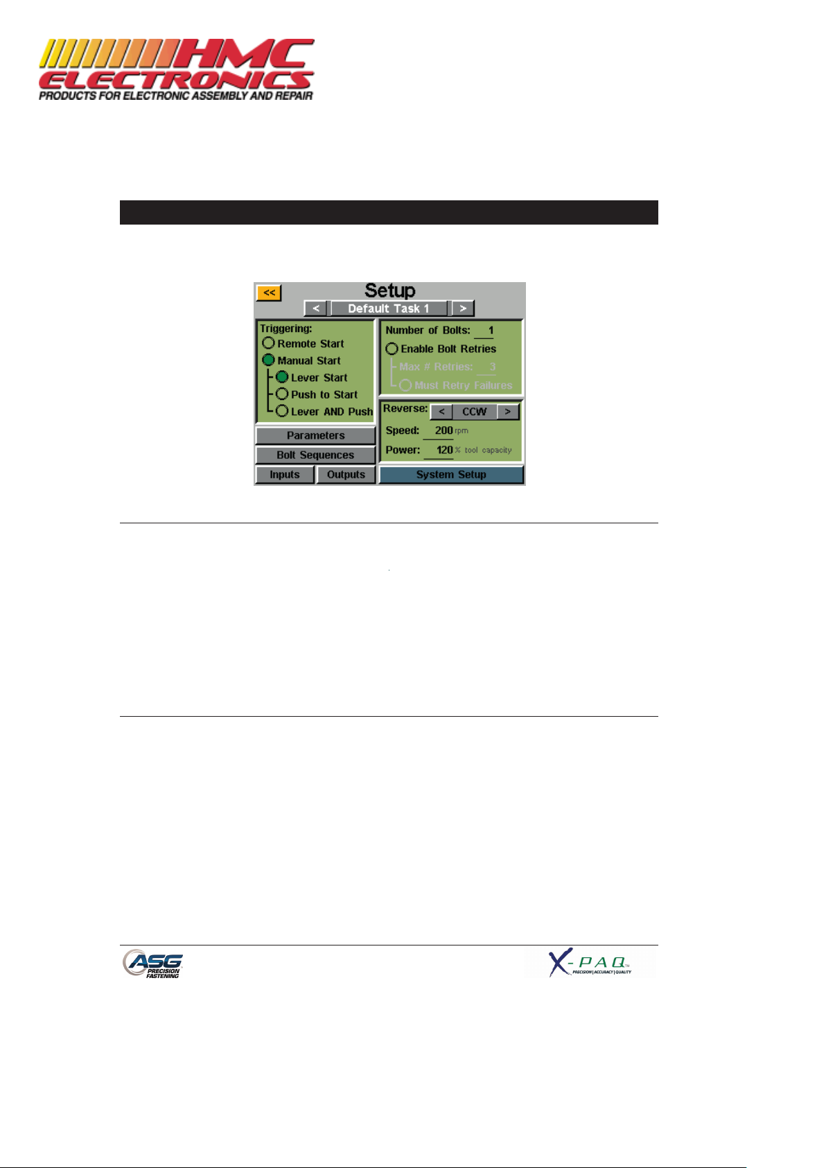
Setup Screen
Entering the setup screen allows you to modify the settings of each task’s parameters, bolt counts, bolt
sequences, inputs, outputs, reverse settings, and triggering.
Tool Triggering:
On the ‘Setup’ screen, each task can be set up to trigger the tool in the way that best fits that task. The
tool can be set up for remote start, lever start (if tool is equipped with a lever), push to start, lever or
push to start (together), or lever and push to start. To select, just tap the radio button next to the
desired option(s).
For remote start applications, the triggering will have to be configured in the ‘Inputs’ section of the Task
Setup screen. See the Input programming section of this manual for more details.
Bolt Counts:
Setting up the bolt counts for each task can be done through the task setup screen. Under the ‘Number
of Bolts:’ window, tap the underlined number to change the number of bolts to be secured on that task.
This will build what some users call a batch. The controller will display the bolt count on the ‘Run Tool’
screen.
The controller will accept up to 999 bolts per task, but once the bolt count rises above 50, individual
bolts cannot be programmed to different parameters in the ‘Bolt Sequences’ screen.
No matter how many bolts are in the batch, a torque or angle control parameter must be assigned to
a given bolt in order for it to run. See the Parameter Setup and Bolt Sequences sections of this
manual for more information.
Documentation Provided By HMC Electronics
33 Springdale Ave. Canton, MA 02021
http://www.hmcelectronics.com
(800) 482-4440
Page 13

Page 13
Bolt Retries:
To enable this feature, tap the radio button on the task setup screen under the number of bolts. Set the
number of retries before lockout by tapping the number and inputting the desired value. A retry is
counted when the tool is put into reverse and triggered. After the designated value of retries have
been achieved, the tool will not attempt another rundown without tapping the ‘reset’ button on the
‘Run Tool’ screen. If bolt retries are not enabled, the controller will advance the bolt count to the next
one in sequence regardless of a pass or fail.
Must Retry Failures:
To enable this feature, tap the radio button on the task setup screen under the bolt retries. With
this feature enabled, any failed rundown will require a retry before proceeding to the next
rundown in sequence. A retry is counted when the tool is put into reverse and triggered
. Once
the previously failed rundown is successfully completed, the bolt count will advance with the next
trigger of the tool. If the attempted numbers of retries are unsuccessful, the tool will be disabled
until the reset button is pressed. See the password screen to enable operator lockout.
Reverse Settings:
In each task, the reverse settings must be defined. More specifically, when the reverse button on the
tool is pressed and released (and the colored LED lights on the tool are flashing), the user must tell the
controller how fast to turn, what direction, and at what percent of the tool’s maximum torque. For
instance, if a 50 inlb tool is connected to the controller, and the Reverse Power is set to 50%, the tool
will be able to use 25 inlb of torque to remove a fastener before the tool stalls. These reverse settings
can be different for each task in the controller if the user wishes, or they can all be set identically for
uniformity.
Reverse can also be disabled by using the arrow button to cycle through CW and CCW to Disabled.
When disabled, the tool can be put in reverse mode by pressing and releasing the reverse button, but
the tool will not run when triggered, a message will appear on the screen indicating that reverse is
currently disabled.
Documentation Provided By HMC Electronics
33 Springdale Ave. Canton, MA 02021
http://www.hmcelectronics.com
(800) 482-4440
Page 14

Page 14
Parameter Setup:
From the task setup screen, select the Parameters button. Shown will be a button for each of the 8
available parameters for that task.
Some useful definitions for the Parameter Setup:
Target Torque/Angle: The value at which the tool should stop the fastener rundown
Torque HL/LL: The High Limit (HL) or Low Limit (LL) of acceptable torque for the fastener in the
user’s process.
Angle HL/LL: The High Limit (HL) or Low Limit (LL) of acceptable angle for the fastener. In
Torque Control Profiles, this monitoring may be disabled by tapping the ‘Angle
Monitoring’ radio button.
Threshold Torque: The torque reading at which the tool enters the fastening cycle. Once the tool
reaches the threshold torque, it will count the angle of revolution until either
the final torque or final angle (depending on Torque or Angle Profile).
Run Down Speed: The speed (rpm) that the tool will run (RH or LH rotation) from the time the tool
is triggered until either the final target is met, or the downshift point is met (if
enabled).
Downshift Torque: The torque at which the tool will shift from the run down speed to the
downshift speed.
Downshift Speed: An optional second speed that the tool may slow down to at a defined torque
limit. This can be disabled by tapping the ‘Enable Downshift’ radio button.
Param Timeout: The time (in seconds) between when the tool is triggered and when it will shut
off on its own if the threshold torque is not reached to enter a fastening cycle.
Documentation Provided By HMC Electronics
33 Springdale Ave. Canton, MA 02021
http://www.hmcelectronics.com
(800) 482-4440
Page 15

To set up a parameter:
1) Select one of the
Parameter
Profile
by tapping the button on the right side of the screen to toggle between the choices.
Note:
Torque Control
Angle Control
Profile Parameters
2) Select the
direction of rotation for the parameter by toggling between ‘clockwise’ and
‘counterclockwise’ at the top of the screen.
3)
Select the torque units by selecting the
selecting the units required.
4)
Name the parameter by selecting the button below the yellow
screen keypad to enter the desired name.
5)
Fill out the rundown characteristics by
keypad to enter the information.
6) Tap the yellow [<<]
button to return to the parameter list and select ‘Yes’ to save the changes.
Page 15
buttons and select either Torque Control Profile
or Angle Control
Profiles Parameters will appear in BLUE
on the parameter list and
will appear in GREEN.
button at the top right hand corner of the screen, then
[<<]
button and using the on
tapping on the underlined areas and using the on
-
-screen
Documentation Provided By HMC Electronics
33 Springdale Ave. Canton, MA 02021
http://www.hmcelectronics.com
(800) 482-4440
Page 16

Page 16
Prevailing Torque
Certain applications (such as self tapping fasteners or locking helical inserts) require compensation for
the prevailing torque of a fastener in the final torque of the rundown. This can be accomplished using
the ‘Calc Prevail Torque’ feature in an angle control parameter. For easy identification, angle control
parameters using the prevailing torque option have a purple outline on the parameter blocks.
The desired compensation can be accomplished by programming a 2-step rundown, starting with an
angle control parameter (with the prevailing torque calculation enabled), followed by a torque control
parameter.
In the example shown above, the fastener is rotated 540 degrees in step 1, during the last 405 degrees
(75%) the prevailing torque is monitored and the average value reported. Step 2 is then performed to a
target of 10 inlb, but the actual applied torque is the final torque of 10.01 inlb plus the 3.21 inlb
calculated for a total of 13.22 inlb.
Utilizing this method will calculate the prevailing torque for each fastener eliminating the need to
determine an average value for all fasteners and then using a standard torque profile only with a larger
target.
Documentation Provided By HMC Electronics
33 Springdale Ave. Canton, MA 02021
http://www.hmcelectronics.com
(800) 482-4440
Page 17

Page 17
Bolt Sequences
The ‘Bolt Sequences’ button allows the user to select which parameter(s) will run for a given bolt inside
each task. To assign a parameter to a bolt, select the bolt number (or multiple bolts if they will all have
the same parameter(s)) then tap the button to the right to access the parameter list. Tap the parameter
name you wish to choose to select that parameter for that bolt.
The ‘Number of Bolts’ is assigned in the ‘Setup’ screen on each task, reference the ‘Setup Screen’
section of this manual for more information.
Multiple bolts can be grouped together and all assigned parameters simultaneously, and they would
need to be selected and ungrouped to program separately again.
Each bolt can have up to 5 parameters assigned to run in sequence as well. A time delay between
parameters may be programmed in this screen should the application require it. When the bolt count is
50 or less, each bolt can be selected separately to assign it any of the 8 available parameters on that
task.
When using multiple parameters on a single bolt, only one trigger pull is required for the bolt, but must
be held until the entire sequence is completed. Releasing the trigger in the middle of the sequence will
result in a ‘sequence aborted’ error.
Should one step of a sequence fail during a rundown, the bolt will fail at that point and not proceed to
the next step of the sequence.
Documentation Provided By HMC Electronics
33 Springdale Ave. Canton, MA 02021
http://www.hmcelectronics.com
(800) 482-4440
Page 18

Page 18
Task Setup
From either the ‘Run Tool’ or ‘Setup’ screens, tapping the task name will bring up the ‘Task Setup’
screen shown below:
All 12 tasks are displayed here and tapping any one will switch to that task.
Renaming and Importing Tasks
From the ‘Task Setup’ menu, pressing and holding on a task name will display the following screen:
Tapping the ‘Rename’ button will allow the user to enter a customized name with the on-screen keypad.
When a USB drive is inserted, the ‘Import’ button will be active, allowing the user to select a task file to
import from the USB drive. The task settings from the imported file will completely over-write the
task shown at the top of this screen, there is no partial import.
Documentation Provided By HMC Electronics
33 Springdale Ave. Canton, MA 02021
http://www.hmcelectronics.com
(800) 482-4440
Page 19

Page 19
Exporting Task Settings to USB
The ASG-CT2500 controller is capable of exporting the task settings to USB for backup and transfer to
other ASG-CT2500 controllers. To accomplish this, insert a USB flash drive with available memory to the
port on the controller.
From the ‘Run Tool’ screen, tap the task name at the top to bring up the ‘Task Setup’ menu
When a USB drive is inserted, the ‘Export Task Files’ button is displayed. Tapping this button will
automatically save the setting files for all 12 tasks in the controller to the USB. The settings will be saved
in the directory: \[Controller Name]\Config Where [Controller Name} is the user defined name
programmed into the ‘Name’ box in the ‘Controller Info’ screen (see Controller Info section of this
manual for more information). This is the same directory you must navigate to when importing a task
file as well.
Documentation Provided By HMC Electronics
33 Springdale Ave. Canton, MA 02021
http://www.hmcelectronics.com
(800) 482-4440
Page 20

Input Programming
There are (8) inputs
, as well as a 24V DC and ground
bottom of the controller.
On the ‘Run Tool’ scre
of the 8 inputs. When an input is active, the light will illuminate
setup.
See the chart at the end of this section for pin location and other technical informati
instructions below detail how to set up various commands through the inputs.
• TASK SELECT
: From the ‘Run Tool’ Screen:
o
Tap the ‘Setup’ Button
o
Make sure the task shown at the top is the one to be programmed.
o
Tap the ‘Inputs’ Button
o Tap the arrow but
ton on the
T
ap the button on the left that
appear in the chart next to each input number. You may now select which input you want to
use to select the task by tapping the ‘Ignore’ button to the right of that input. This will toggle
between ‘H’,’L’, and ‘Ignore’ with each tap. The picture to the right of this button shows what
the controller
is currently seeing on that input. Press t
changes if desired.
If the input requirements are not met
given bolt when the user tries to trigger the tool, the tool will not run and a banner messag
appear on the ‘Run Tool’
screen to notify the user that the input requirements are not met.
Note
: after programming, the controller will switch to the task when that input is keyed,
and will stay there until commanded to switch tasks either via
controls. The input does not need to stay on for the task to remain enabled. If you desire the
input to be active in order for the task to run, we recommend you go to the next section and
setup each bolt in that task to req
Highlight
Page 20
supply
available through the input connector on the
en, there is a row of lights at the bottom showing each
blue to aid in trouble-
shooting and
bottom next to ‘Setup Bolt(s)’ so
that ‘Setup Misc’ appears.
shows the task name
. You should now see a column of buttons
he yellow [<<]
button at the top and save
(signal from an external device is not present or lost)
the input or the touch screen
uire the same input used for the task selection.
on. The
for a
e will
Documentation Provided By HMC Electronics
33 Springdale Ave. Canton, MA 02021
http://www.hmcelectronics.com
(800) 482-4440
Page 21

If a task is being selected through the inputs by an external signal, the task button will not allow
a user to manually select a task, the external input will have to be removed to free the logic and
allo
w the manual selection.
• ENABLE BOLTS
: From the ‘Run Tool’ Screen:
o
Tap the ‘Setup’ Button
o
Make sure the task shown at the top is the one to be programmed.
o
Tap the ‘Inputs’ Button
Assuming that there is only 1 bolt in your sequence, tap the button on the l
You should now see a column of buttons appear in the chart next to each input number. You
may now select which input you want to use to enable the bolt by tapping the ‘Ignore’ button to
the right of that input. This will toggle b
to the right of this button shows what the
yellow [<<]
button at the top and save changes if desired.
Note
: If you have multiple bolts in
you set that up in the ‘Setup’ and ‘Bolt Sequences’ screens prior to completing this step. You
will then want to make sure you set up each bolt you wish to be enabled with the input. For
your convenience
, with multiple bolts a
you to select all bolts and set them up simultaneously.
• REMOTE START
: From the ‘Run Tool’ Screen:
o
Tap the ‘Setup’ Button
o
Make sure the task shown at the top is the one to be
o
Select the ‘Remote Start’ radio button in the ‘Triggering’ section.
o
Tap the ‘Inputs’ Button
o
Tap the arrow button on the
Select the ‘Remote Start’ button on the left side of the scre
buttons appear in the chart next to each input number. You may now select which input you
Highlight
Page 21
eft that says ‘Bolt 1’.
etween ‘H’,’L’, and ‘Ignore’ with each tap. The picture
controller
is currently seeing on that input. Press the
your application
sequence, it is recommended that
n
‘All’ button will appear on the ‘Input’ screen to allow
programmed.
bottom next to ‘Setup Bolt(s)’
so that ‘Setup Misc’ appears.
en. You should now see a column of
Documentation Provided By HMC Electronics
33 Springdale Ave. Canton, MA 02021
http://www.hmcelectronics.com
(800) 482-4440
Page 22

want to use to start the tool by tapping the ‘Ignore’ button to the right of that input. This will
toggle between ‘H’,’L’, and ‘
what the controller
is currently seeing on that input. Press the yellow
save changes if desired.
Note:
Ensure the driver will require the start signal
driver is meant to run. If the start signal is removed in the middle of a rundown, the driver will
stop and give a ‘sequence aborted’ error
Note:
It is recommended that the remote start command
other commands such as a task select, a signal delay of 300ms or greater is recommended for
optimal system performance.
• REVERSE
ROTATION SELECT:
o
Tap the ‘Setup’ Button
o
Make sure the task shown at
o
Tap the ‘Inputs’ Button
o
Tap the arrow button on the
Select the ‘Reverse
’ button on the left side of the screen. You should now see a column of
buttons appe
ar in the chart next to each input number. You may now select which input you
want to use to define left
hand rotation in the tool by tapping the ‘Ignore’ button to the right of
that input. This will toggle between ‘H’,’L’, and ‘Ignore’ with each tap. T
of this button shows what the
button at the top and save changes if desired.
Note:
Ensure the reverse settings on the Task’s ‘Setup’ screen are set to the desire
settings (rotation direction
, speed,
selecting the reverse function must be active as well as the input for the remote start
Highlight
Page 22
Ignore’ with each tap. The picture to the right of this button shows
[<<]
button at the top and
to be active the entire time the
on the ‘Run Tool’ screen.
not be given simultaneously to
From the ‘Run Tool’ Screen:
the top is the one to be programmed.
bottom next to ‘Setup Bolt(s)’
so that ‘Setup Misc’ appears.
he picture to the right
controller
is currently seeing on that input. Press the yellow
and power).
In order for the reverse to function, the input
[<<]
d
Documentation Provided By HMC Electronics
33 Springdale Ave. Canton, MA 02021
http://www.hmcelectronics.com
(800) 482-4440
Page 23

Page 23
function. Only activating the reverse input will merely set the tool to reverse, it will still
require the start signal to run.
• REMOTE RESET: From the ‘Run Tool’ Screen:
o Tap the ‘Setup’ Button
o Make sure the task shown at the top is the one to be programmed.
o Tap the ‘Inputs’ Button
o Tap the arrow button on the bottom next to ‘Setup Bolt(s)’ so that ‘Setup Misc’ appears.
Select the ‘Remote Reset’ button on the left side of the screen. You should now see a column of
buttons appear in the chart next to each input number. You may now select which input you
want to use to reset the tool by tapping the ‘Ignore’ button to the right of that input. This will
toggle between ‘H’,’L’, and ‘Ignore’ with each tap. The picture to the right of this button shows
what the controller is currently seeing on that input. Press the yellow [<<] button at the top and
save changes if desired.
• REMOTE HALT: From the ‘Run Tool’ Screen:
o Tap the ‘Setup’ Button
o Make sure the task shown at the top is the one to be programmed.
o Tap the ‘Inputs’ Button
o Tap the arrow button on the bottom next to ‘Setup Bolt(s)’ so that ‘Setup Misc’ appears.
Highlight
Highlight
Documentation Provided By HMC Electronics
33 Springdale Ave. Canton, MA 02021
http://www.hmcelectronics.com
(800) 482-4440
Page 24

Select the ‘Remote Halt’ button on the left side of the screen. You should now see a column of
buttons appear in the chart next to each input number. You may now select which input you
want to use to halt the
tool by tapping the ‘Ignore’ button to the right of that input. This will
toggle between ‘H’,’L’, and ‘Ignore’ with each tap. The picture to the right of this button shows
what the controller
is currently seeing on that input. Press the yellow
save changes if desired.
Note:
If the remote halt is used during a rundown to halt operations, when the halt
signal is removed, the tool trigger must be released before the tool will start again. This is true
for manual and remote
triggering.
Highlight
Page 24
[<<]
but
ton at the top and
Documentation Provided By HMC Electronics
33 Springdale Ave. Canton, MA 02021
http://www.hmcelectronics.com
(800) 482-4440
Page 25

Output Programming
There are (8) programmable
outputs, 24V DC, and ground
connector on the bottom of the controller. See the chart at the end of this section for pin location and
other technical information.
All the outputs can be set up with the following instructions from the ‘Run
Tool’ Screen:
• Tap the ‘Setup’ Button
o
Make sure the task shown at the top is the one to be programmed.
• Tap the ‘Outputs’ Button
Select an available output
button by tapping the ‘none’ button. Under the ‘Event’ heading, select the
appropriate radio button. Select the type of output you would like under the ‘Behavior’ heading, and if
necessary input the time intervals for the non
enter the value you wish on the on
-
will appear in red until they are saved by exiting the screen with the yellow
Note:
Back on the ‘Outputs’ screen
your device
by tapping the ‘Test’ button next to each output.
AVAILABLE OUTPUT CRITERIA:
• BOLT - SUCCESS
: (All torque and angle requirements fall within the predefined acceptable
ranges of the pro
grammed parameter)
• BOLT – FAIL LOW
: (Any torque or angle requirement fell below the predefined acceptable
ranges of the programmed parameter)
• BOLT – FAIL HIGH
: (Any torque or angle requirement fell above the predefined acceptable
ranges of the programmed
• BATCH ACCEPT
: (All bolts or cycles required in the task are complete and within the acceptable
ranges)
Page 25
supply
available through the output
-solid outputs. To adjust th
ese values, tap on the number,
screen keypad, then tap the enter button. Any un
-
[<<]
button.
, you will have the opportunity to test the output signal to
parameter)
saved changes
Documentation Provided By HMC Electronics
33 Springdale Ave. Canton, MA 02021
http://www.hmcelectronics.com
(800) 482-4440
Page 26

• BATCH REJECT
: (Some portion of the task did not complete within acceptable parameters or the
task was aborted)
• TOOL TRIGGERED:
(All triggering
output is only available as a solid output, not momentary or repeating)
• TORQUE > THRESH:
(The current torque reading from the tool is greater than the programmed
threshold torque in the pa
rameter being run. This output is only available as a solid output, not
momentary or repeating)
Note:
Ensure compatibility of the output receiving device with the user’s programmed signal
duration. Signal pulses less than 50ms could possibly be interpr
Page 26
criteria as defined in the setup screen have been satisfied. This
eted as noise by the receiving device.
Documentation Provided By HMC Electronics
33 Springdale Ave. Canton, MA 02021
http://www.hmcelectronics.com
(800) 482-4440
Page 27

Input/Output Port Pin Guide
Notes:
All inputs are optoisolated
Outputs are mechanical dry contacts
Page 27
– sealed relays.
Documentation Provided By HMC Electronics
33 Springdale Ave. Canton, MA 02021
http://www.hmcelectronics.com
(800) 482-4440
Page 28

Listed 24VDC pins are supply pins, do not hook up external 24V
damage can occur. Listed Ground pins are tied to the earth ground of the controller’s input power
supply, do not hook up to external equipment grounds to avoid ground conflicts.
Do not use CT2500 outputs to switch high indu
Page 28
DC to the controller, internal
ctive loads –
damage to relays can occur.
Documentation Provided By HMC Electronics
33 Springdale Ave. Canton, MA 02021
http://www.hmcelectronics.com
(800) 482-4440
Page 29

Page 29
Graph Screens
In order to assist the user with setting up and trouble-shooting problem joints, the latest rundown is
stored in the controller in graph form. From the ‘Run Tool’ screen, tap the ‘Graph’ button at the bottom
of the screen. Along the bottom of the screen can be found the available graphs, tap the appropriate
button to view:
• Torque vs. Time:
Graphs the last rundown with Torque on the Y axis in whatever units are
specified in the parameter, and Time on the X axis in milliseconds (ms).
• Angle vs. Time:
Graphs the last rundown with Angle on the Y axis in degrees (deg), and Time on
the X axis in milliseconds (ms).
• Torque vs. Angle:
Graphs the last rundown with Torque on the Y axis in whatever units are
specified in the parameter, and Angle on the X axis in degrees (deg).
Documentation Provided By HMC Electronics
33 Springdale Ave. Canton, MA 02021
http://www.hmcelectronics.com
(800) 482-4440
Page 30

• Speed vs. Time:
Graphs the last rundown with Speed on the Y axis in rotations per minute
(rpm), and Time on the X axis in milliseconds (ms).
• Power vs. Time: G
raphs the last rundown with Power on the Y axis in Watts (W), and Time on
the X axis in milliseconds (ms).
In each graph there is a ‘Legend’ button on the top of the screen. Tapping this button will affix labels to
the lines overlaying each graph (where
defined by the parameter of the rundown.
just be aware that the graph will change with each cycle of the tool since the controll
most recent rundown in graph form.
NOTE:
The default view of each graph begins with Time or Angle equal to 0, which is defined by
your Threshold set in the parameter of the rundown. Tapping on the graph once, will switch the view to
a
wider view that begins with the time the tool is triggered
view.
Page 30
applicable) showing High Limits, Low Limits, Thresholds, etc as
The tool can be used while the controller displays the graph,
er only stores the
. Tap one more time to return to the original
Documentation Provided By HMC Electronics
33 Springdale Ave. Canton, MA 02021
http://www.hmcelectronics.com
(800) 482-4440
Page 31

Page 31
Graph Data Export to USB (GUI Firmware v2.2.0.0 and later)
In order to enable the graph data export function, a key file must be saved to a USB flash drive and
inserted to the controller. This file can be obtained from ASG and saved to the USB main directory
inside a folder named ‘Keys’.
Once inserted, an icon will appear on the ‘Run Tool’ screen next to the ‘Tool’ button indicating the
feature is enabled. Upon the completion of each rundown, the controller will export the graph data to
the USB drive. It will be saved in the directory [Controller Name]\Graphs where [Controller Name] is
whatever is programmed in under the ‘Controller Info’ menu.
During the data export, a banner message will appear notifying the user that the export is in progress. It
is not recommended that this feature be used during production because the tool will not operate
during the data export. The tool will resume its normal operation once the export is complete.
The available data for export in this process is the following:
• Task Number
• Bolt Number
• Sequence Step
• Time (in ms since tool was triggered)
• Prevailing Torque
• Torque
• Torque Units
• Angle Total
• Angle since Threshold Torque
Documentation Provided By HMC Electronics
33 Springdale Ave. Canton, MA 02021
http://www.hmcelectronics.com
(800) 482-4440
Page 32

Data Screen
For data traceability, rundown information is stored in table form for view and download from the
controller. To access this data, tap the ‘Data’ button on the bot
100 rundowns sinc
e the last controller reboot is available to view on screen.
on screen is:
• Date/Time
• Bolt Number
•
Result (Good, High Torque, Low Angle, etc)
• Tool Cycle
• Target Torque/Angle
• Prevailing Torque
•
Applied Torque (Sum of Final Torque a
• Final Torque
• Final Angle
To page through the on-
screen data, use the ‘Next’ and ‘Previous’ buttons available at the bottom of the
screen.
An expanded data set is stored in the controller’s internal memory, the number of rundowns s
limited only by the memory of the controller, and once filled is replaced in a first in/first out basis.
Refer to the ‘Downloading Data’
section of this manual for more information on how to retrieve this
data.
NOTE
: T
urning off the controller will clear the table of all data. The data is retained in memory
for download, but will not be available
Page 32
tom of the ‘Run Tool’ screen.
The data available to view
nd Prevailing Torque)
for on-screen viewing.
The last
tored is
Documentation Provided By HMC Electronics
33 Springdale Ave. Canton, MA 02021
http://www.hmcelectronics.com
(800) 482-4440
Page 33

Page 33
Erasing Data
To erase the data shown on the screen, tap the ‘Erase’ button at the bottom of the chart. A screen will
ask you to confirm your intentions to erase the data before the data is cleared. NOTE:
Erasing the data
with this button will not clear the data from the internal memory of the controller; it will merely remove
it from view in the table. Any erased data is still available for download to USB as described in the next
section.
Downloading Data
To download data to a USB flash drive, insert a flash drive with available memory into the port on the
bottom of the controller. Tap the ‘Export Data’ button at the bottom of the data table, and then select
either to download just the Data Screen Contents, or choose a date range for which you wish to
download the data. Tap the ‘Export’ button to copy the information to the flash drive.
To view the data downloaded to USB, insert the flash drive into a computer and open to view the files
and folders. The controller will create a folder on your flash drive called your controller name (if you
have named your controller ‘Station 1’ in the ‘Controller Information’ screen, you will find a folder on
your flash drive named ‘Station 1’. See the Controller Information section of this manual for more
information). Inside this folder will be a folder called ‘Data’ which contains the files exported to the
flash drive. Note: if multiple days are selected for download, the controller will save a file for each day
on the flash drive. For example, if 5 days are selected for data export, you will find 5 files on the flash
drive (unless the tool was not used during some of those days).
Documentation Provided By HMC Electronics
33 Springdale Ave. Canton, MA 02021
http://www.hmcelectronics.com
(800) 482-4440
Page 34

Page 34
Data available in these downloaded files includes the following:
• Date
• Time
• Tool Model Number
• Tool Serial Number
• Tool Cycle Number
• Task Name
• Bolt Number
• Torque Units
• Parameter Target
• Prevailing Torque Value
• Applied Torque
• Final Torque Reading
• Final Angle Reading
• Cycle Time
• Result Note
• Parameter Name
• Parameter Type
• Parameter Threshold Torque
• Parameter Torque HL
• Parameter Torque LL
• Parameter Angle HL
• Parameter Angle LL
• Downshift Torque
• Rundown Speed
• Downshift Speed
• Hand of Rotation
The downloaded files are a CSV format (comma separated value) and will open automatically in typical
spreadsheet programs.
Documentation Provided By HMC Electronics
33 Springdale Ave. Canton, MA 02021
http://www.hmcelectronics.com
(800) 482-4440
Page 35

Page 35
System Setup Screen
The ‘System Setup’ screen allows the user to set system controls and tool settings. See the following
sections for further information.
Passwords
From the ‘System Setup’ screen, tap the ‘Passwords’ button. The controller allows (3) individual
passwords, each password allows access to the controller when locked. Each password allows full
access to unlock the controller. When a controller is locked, the controller will still navigate to most
screens and settings will be viewable. If it is locked and a user tries to access a protected field, the
controller will prompt for a password to allow access.
Creating a User(s)/Password(s)
: Tap an available user button and enter a User Name when prompted.
Next enter a password, and then confirm the password. The controller will return to the ‘Passwords’
screen, and the entered user name should be visible in one of the buttons. Return to the ‘Setup’ screen
by tapping the [<<] button twice. You will notice that the screen appears differently than before, many
of the fields are “greyed-out” signifying that the controller is locked and those fields are no longer
accessible.
Documentation Provided By HMC Electronics
33 Springdale Ave. Canton, MA 02021
http://www.hmcelectronics.com
(800) 482-4440
Page 36

Modifying features in a locked controller
and tap the appropriate button or number. The controller will then prompt the user for a password to
unlock the controller. Once a password is accepted, settings can be changed on any screen. To re
the controller again after modifications hav
corner of the ‘Run Tool’ screen.
Deleting User(s)/Password(s)
:
From the ‘Passwords’ screen, tap the name of the user that is to be
deleted, enter the password when prompted. The screen will sh
create a button next to that user called ‘Delete User’. Tap the ‘Delete User’ button to remove the user
from the controller.
NOTE
: It is recommended that one ID and password be programmed and stored in a safe
l
ocation to prevent from accidental locking of the controller that is left unlocked.
Page 36
: Navigate to the setting or feature that needs to be mod
e been made, tap the ‘Lock’ button at the
bottom
ow that the password is now active, and
ified
-lock
right-hand
Documentation Provided By HMC Electronics
33 Springdale Ave. Canton, MA 02021
http://www.hmcelectronics.com
(800) 482-4440
Page 37

Page 37
Date/Time Settings
To set the controller’s date and time, tap the ‘Date/Time’ button on the ‘System Setup’ screen. Adjust
the date and time with the up and down arrow keys above and below each number. Note: the time is
formatted in a 24 hour format, and the date is in MM/DD/YY format. Tap the [<<] button to return to
the previous screen and save changes.
Tool Trigger Sensitivity
The controller allows the user to set the sensitivity of both the Push-to-Start and the Lever Start (when
equipped) features of the ASG-SD2500 tool to suit individual user or application preferences. To adjust
these settings, tap the ‘Tool Trig Sensitivity’ button on the ‘System’ screen.
On the ‘Trigger Sensitivity’ screen there are two slider bars, one for the Lever, and one for the Push-toStart. On each slider there is the following:
• Yellow bar – shows the minimum trigger reading
• Red bar – shows the maximum trigger reading
• White bar – shows the current trigger reading
• Green bar - shows the trigger reading threshold
Documentation Provided By HMC Electronics
33 Springdale Ave. Canton, MA 02021
http://www.hmcelectronics.com
(800) 482-4440
Page 38

To
adjust the threshold, use the up and down arrow keys to move the green bar up or down the slider.
To test, push the lever or pull chuck to move the white bar up to the green threshold bar
tool begins to run when desired.
Tool Calibration
To view the calibration value of the tool connected to the controller, tap the ‘Tool Cal’ button on the
‘System’ screen. The calibration value will be displayed, and can be modified if required.
CAUTION
: Tapping on the Calibration Value will take you
manually changed.
This screen is for qualified calibration technicians only.
calibration value of the tool could lead to inaccurate torque readings and potential tool damage.
Page 38
to a screen where the value can be
Improperly changing the
and verify the
Documentation Provided By HMC Electronics
33 Springdale Ave. Canton, MA 02021
http://www.hmcelectronics.com
(800) 482-4440
Page 39

Controller Information
To view basic information about the controller and to give the controller a name, tap the ‘Controller
Info’ button on the ‘System’ screen. This screen displays the following:
• Controller Name
• Controller Serial Number
• GUI Board Firmware Vers
ion
•
Controller Board Firmware Version
Changing the Controller Name:
To change the controller name, tap the button on the ‘Controller
Information’ screen that shows the current name,
NOTE: When exporting dat
a to a USB flash drive from the controller, the name of the folder
created on that flash drive will be the same name as the controller. This will assist the user if
downloading data from multiple controllers onto one single flash drive. See the Data Scre
more information on downloading data to USB.
Firmware Update
When a USB flash drive is inserted to the controller, the ‘Firmware Update’ buttons are active on the
‘Controller Information’ screen. Tapping
select a file to upload to the controller. The firmware file can be obtained from ASG, contact ASG
Customer Service for more information and eligibility.
The USB flash drive must be FAT32 formatted for this feature to work pro
a properly formatted flash drive can result in firmware corruption and require the controller to be
serviced at ASG to reset it to proper function.
Page 39
and then
enter the new name on the screen.
the button will allow you to navigat
e to the flash drive and
perly. Failure to use
en section for
Documentation Provided By HMC Electronics
33 Springdale Ave. Canton, MA 02021
http://www.hmcelectronics.com
(800) 482-4440
Page 40

Page 40
Touch Screen Calibration
Should the user feel the need to recalibrate the touch screen, this option is available under the ‘System’
screen. Tap the ‘Touch Screen Cal’ button and follow the on-screen directions to complete this process.
LCD Brightness
Should the controller be used in extremely dark or light environments, the LCD touch screen brightness
can be adjusted under the ‘System’ screen. Use the up and down arrow buttons to adjust the
brightness. The controller comes factory set at 60%.
Service & Warranty
Service
Should a product need to be returned for any reason, please contact ASG for a return authorization
number prior to shipping an item for repair. Call us at (888) 486-6163 or email us at service@asgjergens.com
• No items will be received without prior authorization
•
Be sure to include a brief description of the problem, your company name, address, phone
number and contact name
•
An ASG technician will contact you with a quotation and information regarding your repair
Warranty
ASG Precision Fastening warrants to the original purchaser buying an ASG-SD2500 product with the
intention of use rather than for resale, for a period of one (1) year from the first in-service date or one
million (1,000,000) cycles.
Within the warranty period, ASG Precision Fastening will replace or repair those items found to be
defective or otherwise fail to conform. The buyer’s remedies with respect to any item found to be
defective or otherwise not conforming shall be limited EXCLUSIVELY to the right of replacement. In no
event shall ASG be liable for any incidental special or consequential damages or for damages in the
nature of penalties.
Disclaimer: Seller makes no other warranty whatever, expressed or implied, and all implied warranties of
merchantability and fitness for a particular purpose are disclaimed and excluded from this transaction
and shall not apply to the goods sold hereunder.
Documentation Provided By HMC Electronics
33 Springdale Ave. Canton, MA 02021
http://www.hmcelectronics.com
(800) 482-4440
 Loading...