

Page 1
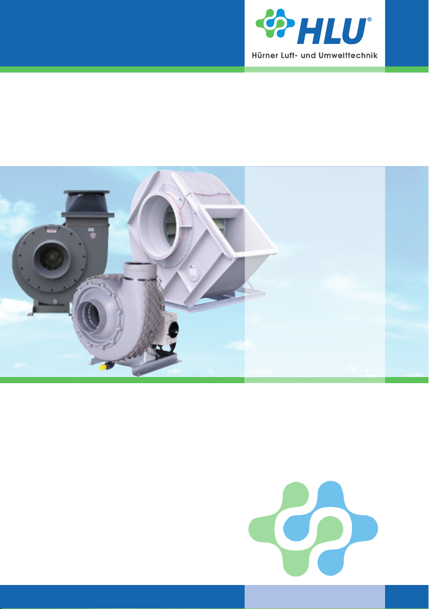
Operating manual
Centrifugal fans
HF R ...-15 / 17 D / R
Size 125 up to 500
HF R ...-13 D / R
Size 450 up to 1250
HF R ...-16 R
Size 160 up to 400
HF R ...-48 R
Size 50 up to 200
These operating instructions are valid for the standard and ATEX versions.
www.hlu.eu
Size 80 up to 140
RV 20
RV 28
Size 200 up to 800
RV 45/63
Size 160 up to 1250
MRV 45/63
Size 160 up to 355
Page 2

Operating manual
Centrifugal fans
2
These operating instruction are part of the fan and must be available
to the operating personnel at all times. The safety information given
in these instructions must be followed. In the event of a fan resale,
these operating instructions must be included with the equipment
supplied.
HF R | RV | MRV
06.2019
Translation
In the event of supply or subsequent sale into the countries
of the EEA, the operating instructions must be translated into
the language of the user country accordingly.
If the translated text contains divergences, always refer to
the wording of the original (German) operating instructions,
or contact the manufacturer.
www.hlu.eu
Page 3

Operating manual
Centrifugal fans
HF R | RV | MRV
1. Content
1.1 Index
1. Content 3
1.1 Index 3
1.2 EC-/EU-Declarations of conformity 4
2. Construction and correct use for the intended application 6
2.1 Construction of the fan 6
2.2 Correct use for the intended application and eld of application 10
3. Product specic data 12
3.1 General data 15
3.2 Power supply (see motor type label) 16
4. Safety 16
4.1 Signs and explanations 16
4.2 Fan marking 17
4.3 Built-in safety systems (to be implemented by the user) 18
4.4 Interfaces of the fan 19
4.5 Safety measures (to be implemented by the user) 19
4.6 User‘s responsibilities 19
5. General warning symbols 20
5.1 Hazards 20
5.2 Operating and hazardous areas on the fan 20
5.3 Installation of spare and wear parts 21
6. Installation 22
6.1 Scope of supplies 22
6.2 Transport and packing 22
6.3 Delivery (also with spare and substitute parts) 22
6.4 Intermediate storage 22
6.5 Transport to the place of installation (at the customer‘s site) 23
6.6 Installation, mounting, Initial commissioning 24
6.7 Operating modes 25
7. Operation 25
8. Maintenance / Cleaning 26
8.1 Cleaning 27
8.2 Lubrication 28
8.3 Tensioning of V-belts 31
8.4 Inspection interval / Function checking 33
8.5 Vibrations 34
8.6 Tightening torques for bolt connections 34
8.7 General hints for maintenance 35
8.8 Checks 35
9. Troubles, causes and measures 36
10. Emergency 37
11. Dismantling / Disposal 37
www.hlu.eu
3
06.2019
Page 4
EC-/EU-
Declaration of Conformity
Operating manual
Centrifugal fans
4
HF R | RV | MRV
1.2 EC-/EU-Declaration of Conformity
For the purpose of
J EC Machine Directive 2006/42/EC, Annex II A for Machines
J EC Low Voltage Directive 2014/35/EU, Annex III
J EMC Directive 2014/30/EU, Annex I and II
We hereby declare that the construction type of the supplied version of:
HF R …, HF D …, HF A …, AX 58 …, RV …, MRV …, SDR …
Manufacturer: Hürner Luft- und Umwelttechnik GmbH
in the delivered version, as a separate component within an installation, complies with the above regulations and
the following standards or normative documents:
DIN EN ISO 12100:2011
Reference to the following standards is made additionally in the DIN EN ISO 12100:
DIN EN ISO 13857:2008, DIN EN 349:2009, DIN EN ISO 14120:2016, DIN EN ISO 13732-1:2008,
DIN EN 60204-1:2014
DIN ISO 21940-11:2017 Procedures and tolerances for rotors with rigid behaviour
DIN EN 61000-6-4:2011
DIN EN 61000-6-2:2011
DIN EN 82079-1:2013 Preparation of instructions - Structuring, content and presentation
VDMA 24167:1994 Fans - Safety requirements
precluding responsibility for components provided or mounted by the customer. It the fan is modied without prior
agreement with HLU, this declaration is void.
Ernst-Hürner-Straße
35325 Mücke-Atzenhain
Germany
Directive / Standard Title
Safety of machinery - General principles for design – Risk assessment and
risk reduction
Electromagnetic compatibility, Generic standards - Immunity for industrial environments
Electromagnetic compatibility, Generic standards; Emission standard for industrial environments
HLU Systemtechnik GmbH
Sälzerstraße 20a
56235 Ransbach-Baumbach
Germany
06.2019
Name and address of the persons, who are authorized, to assort the technical documents:
J Anne-Christin Vögl-Schmitt, Hürner Luft- und Umwelttechnik GmbH, Ernst-Hürner-Straße,
35325 Mücke-Atzenhain, Germany
J Marcel Pfeifer, HLU Systemtechnik GmbH, Sälzerstraße 20a, 56235 Ransbach-Baumbach, Germany
www.hlu.eu
Page 5

EC-/EU-
Declaration of Conformity
Operating manual
Centrifugal fans
HF R | RV | MRV
5
For the purpose of
J EC Directive 2014/34/EU (ATEX) concerning equipment and protective systems
intended for use in potentially explosive atmospheres
We hereby declare that the construction type of the supplied version of:
HF R …, HF D …, HF A … PTB 03 ATEX D089
RV …, MRV … PTB 04 ATEX D097
SDR … PTB 04 ATEX D098
AX 58 … PTB 04 ATEX D099
Manufacturer: Hürner Luft- und Umwelttechnik GmbH
conrm in exclusive responsibility to produce solely in combination with the ATEX-name plate and the
individual test report 2.2 according DIN EN 10204:2004 in the delivered version, as a separate component
within an installation, complies with the standards / regulations of the general declaration of conformity, the
above regulations and the following standards or normative documents:
Directive / Standard Title
DIN EN 1127-1:2011
DIN EN 13237:2013
DIN EN 14986:2017 Design of fans working in potentially explosive atmospheres
DIN EN 15198:2007
DIN EN ISO 80079-36:2016 Part 36: Basic method and requirements
DIN EN ISO 80079-37:2016 Part 37: Protection by constructional safety „c“
precluding responsibility for components provided or mounted by the customer. It the fan is modied without prior
agreement with HLU, this declaration is void.
Ernst-Hürner-Straße
35325 Mücke-Atzenhain
Germany
Explosion prevention and protection - Part 1: Basic concepts and
methodology
Terms and denitions for equipment and protective systems intended for
use in potentially explosive atmospheres
Methodology for the risk assessment of non-electrical equipment and components for intended use in potentially explosive atmospheres
HLU Systemtechnik GmbH
Sälzerstraße 20a
56235 Ransbach-Baumbach
Germany
Name and address of the persons, who are authorized, to assort the technical documents:
J Anne-Christin Vögl-Schmitt, Hürner Luft- und Umwelttechnik GmbH, Ernst-Hürner-Straße,
35325 Mücke-Atzenhain, Germany
J Marcel Pfeifer, HLU Systemtechnik GmbH, Sälzerstraße 20a, 56235 Ransbach-Baumbach, Germany
www.hlu.eu
06.2019
Page 6
Operating manual
Centrifugal fans
6
2. Construction and correct use for the intended application
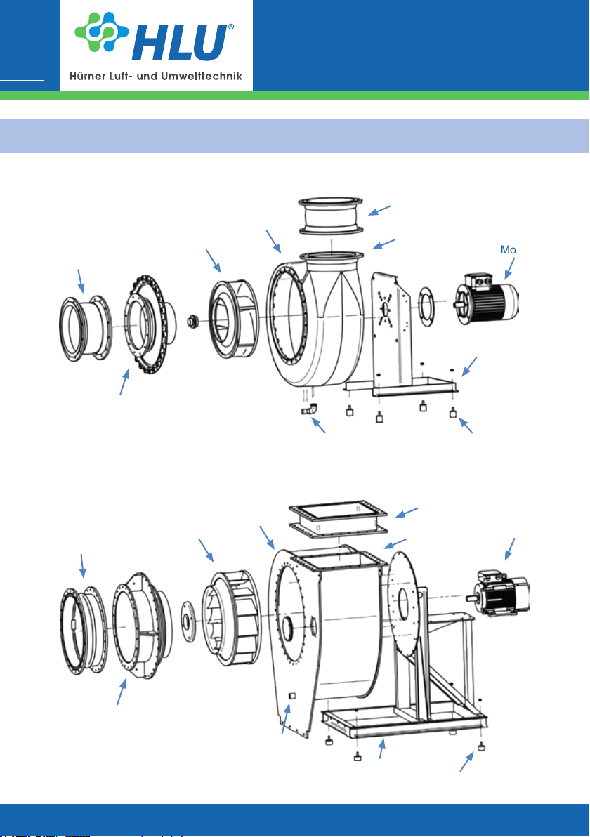
2.1 Construction of the fans
Impeller
Sleeve
Housing cover with
inlet adapter
HF R | RV | MRV
Housing
Condensate drain
Sleeve
Outlet adapter
Motor
Frame
Vibration absorber
06.2019
Fig. 1a| Overview of the fan HF R ...-15 / 17 D | Direct drive
Housing
Impeller
Sleeve
Housing cover with
inlet adapter
Condensate drain
Fig. 1b| Overview of the fan HF R ...- 16 / 13 D | Direct drive
Frame
Sleeve
Outlet adapter
Vibration absorber
www.hlu.eu
Motor
Page 7

Operating manual
Centrifugal fans
HF R | RV | MRV
7
Impeller
Sleeve
Housing cover with
inlet adapter
Fig. 1c| Overview of the fan HF R ...-48 R | Belt drive
Housing
Condensate drain
Sleeve
Outlet adapter
Flange bearing
Vibration absorber
Belt drive
drive cover
Motor
Frame
www.hlu.eu
06.2019
Page 8
Operating manual
Centrifugal fans
8
HF R | RV | MRV
06.2019
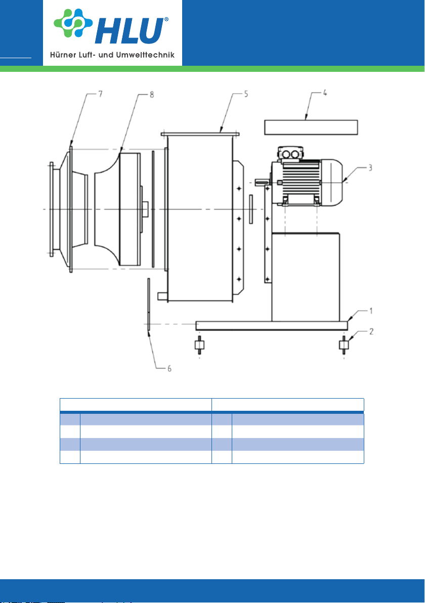
Designation Designation
1 Frame 5 Housing
2 Vibration dampers 6 Support
3 Motor 7 Housing cover with inlet adapter
4 Motor cover (opt.) 8 Impeller
Fig. 1d| Overview of the fan HF RV / MRV | Direct drive
www.hlu.eu
Page 9
Operating manual
Centrifugal fans
HF R | RV | MRV
9
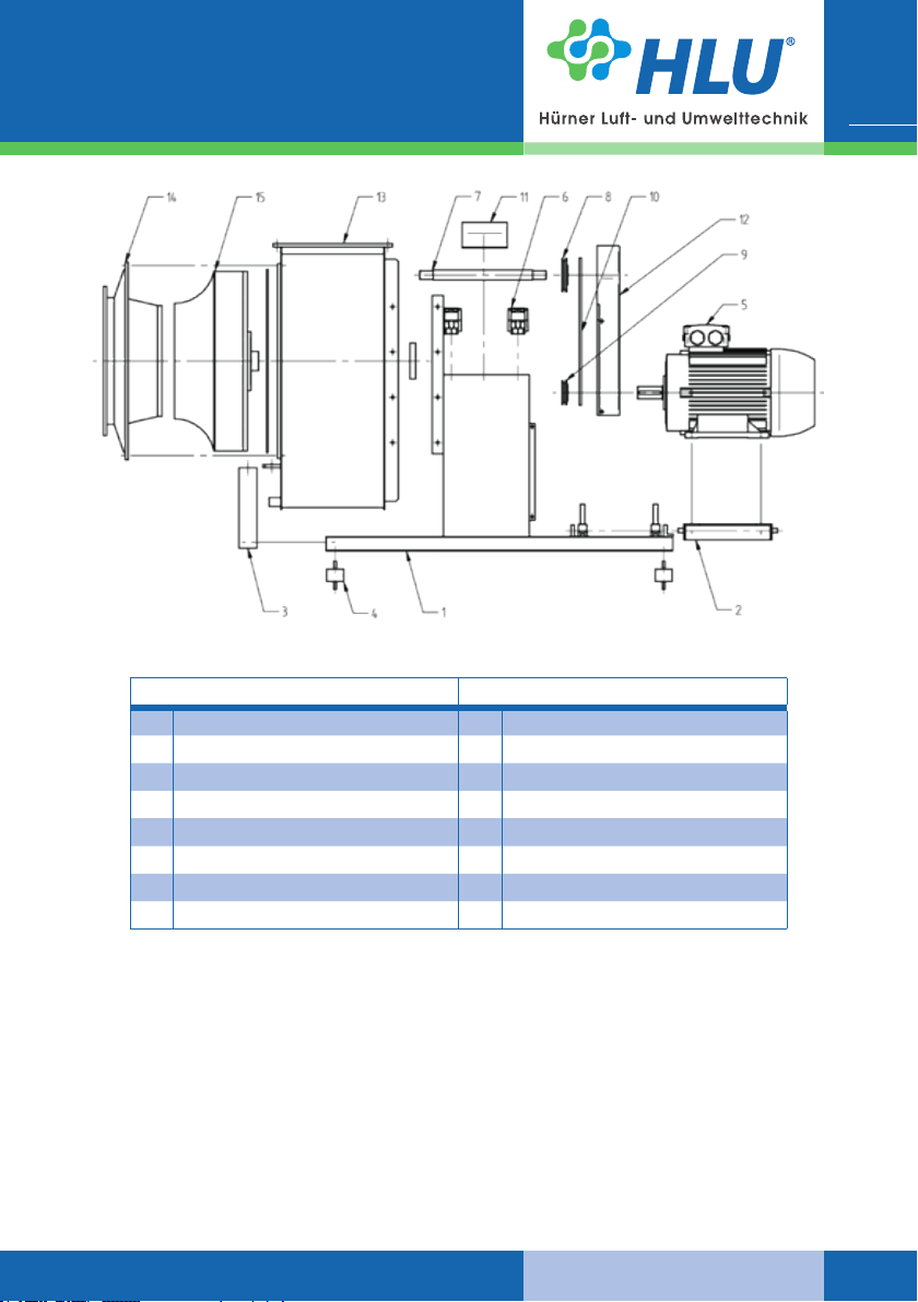
Designation Designation
1 Frame 9 Belt pulley, Motor
2 Motor-clamp 10 V-Belt
3 Support 11 Shaft cover
4 Vibration dampers 12 Driver cover
5 Motor 13 Housing
6 Bearing 14 Housing cover with inlet adapter
7 Shaft 15 Impeller
8 Belt pulley, Fan
Fig. 1e| Overview of the fan HF RV / MRV | Belt drive
www.hlu.eu
06.2019
Page 10

Operating manual
Centrifugal fans
10
Centrifugal fans consist of the following main assemblies: Frame, housing, impeller and
drive motor. They are delivered with direct drive (impeller on motor shaft) (except for the type
HF R …-48 R), as well as with belt drive (transmission motor-belt-impeller shaft).
The housings of the series HF R …-15 / 17 D R are sintered with polyethylene (PEs. RAL7036)
as standard. The housings of the other series are manufactured in self-supporting welded cons-
truction with dierent thermoplastics adapted to the particular conditions of use. They have a
housing cap on the inlet side, which allows the mounting / dismounting of the impeller after
demounting. For the production series RV 45 and RV 63 optionally also moulded casings made
from PVC and PPs are used. These consist of two shells in which the impellers are laid before
welding. Demounting of the impellers is not possible.
The housing is performed with a splinter protection, has on its deepest point (lateral) condensate drain drillings and it can be delivered with revision opening if requested.
The impeller is statically and dynamically balanced (min. quality class G 6.3 acc. to DIN ISO
21940-11). The vibration limits correspond to the ISO 14964 standard. Depending on the speed
and other procedural parameters, various special materials are used as impeller materials in
addition to thermoplastic. Main dierentiating factor of these series are the dierent bladings of
the impellers and the housing construction.
On the type label are registered the maximum impeller r.p.m.s. For increasing the impeller
r.p.m., previous consultation of the manufacturer is indispensable.
For fans which are appropriated for the use in Ex-zone 1 the housing and the impeller are made
of electrical conductive thermoplastics. The standard thermoplastic plastic fan is not equipped
with shaft sealing.
The HF R ...- 13 D / R DS2 / DS3 series has a Kera seal as standard grown.
The exhaust uid is aspirated axially by the rotating impeller and transported radially to the
outlet in the helicoidal housing. The applied energy is converted into mass ow and pressure
increase of the exhaust uid in the impeller.
HF R | RV | MRV
06.2019
2.2 Correct use for the intended application and eld of application
The fans are suitable for exhausting aggressive, dust-free, low-aerosol gases and clean air.
Explosive atmosphere can be exhausted only using fans designed specially for this application.
The permissible gas temperatures for the most frequently used plastics materials are generally
with PVC: 0 °C bis 50 °C,
with PE, PE-FR (PEs) -20 °C to 60 °C,
with PP, PP-FR (PPs): 0 °C to 70 °C,
and with PVDF: -10 °C to 100 °C.
These temperatures must not be exceeded.
Depending on gas composition and impeller speed, these temperature ranges must be check
and restricted, if necessary. With particularly aggressive media, the reductions must be checked
and determined individually in each case. The max. ambient temperature is 40 °C.
Sucient cooling can be ensured regardless of the volume ow, in accordance with the
above-mentioned conditions.
The fan was developed, designed and built exclusively for industrial and commercial use. Using
the fan for domestic purposes is excluded.
www.hlu.eu
Page 11
Operating manual
Centrifugal fans
HF R | RV | MRV
Installation inside the explosion-hazarded area:
Installation inside the explosion-hazarded area is not permissible,
unless the fan is provided explicitly for this purpose (see type label
Chapter 4.2).
If the fan for an installation with an open inlet or outlet or is provided
for an inlet-side duct connection as part of a larger installation, the
operator is obligated to prevent the penetration of foreign bodies that
can cause ignition according to DIN EN 14 986, point 4.22.
Repair and maintenance works of explosion-proof fans may only be
performed by qualied persons in the explosion protection by
using original spare parts.
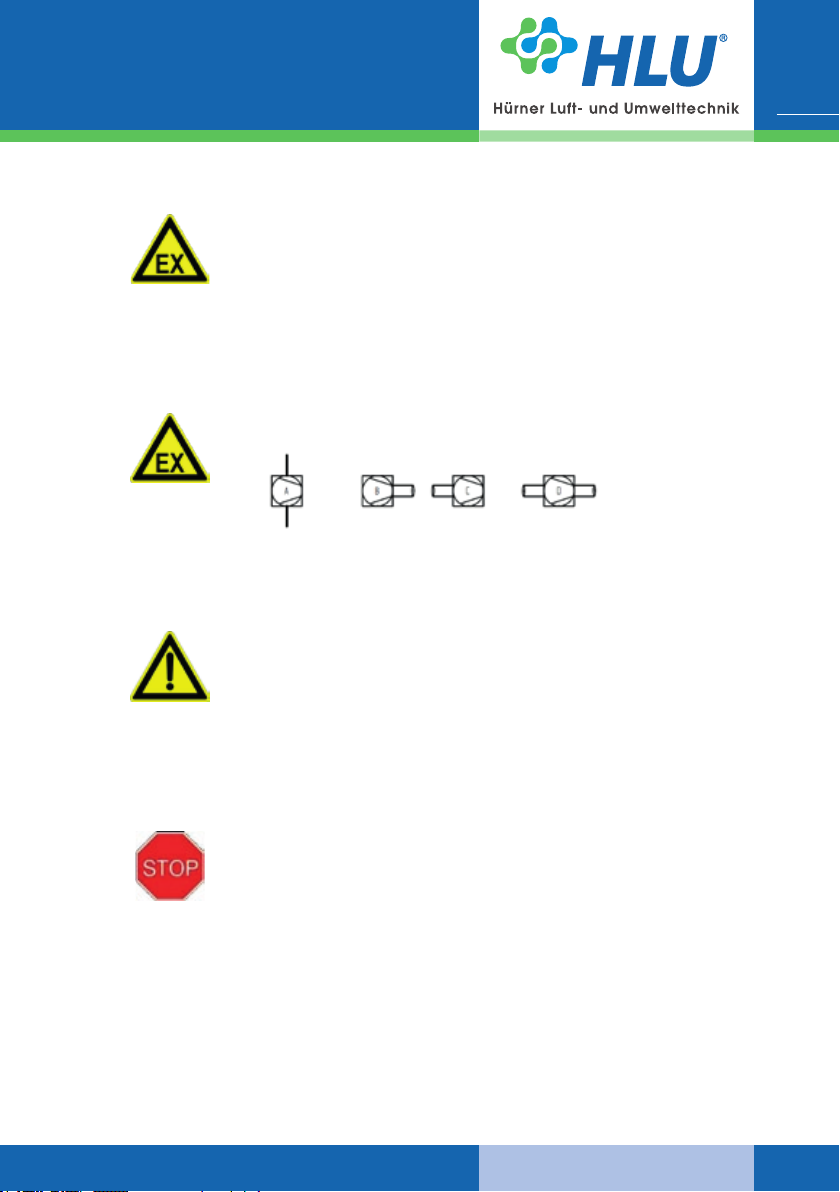
If the fan has an open inlet and / or outlet (Type A, B, C according to
ISO 13349), the fan must have the same category inside and outside.
Types of connection
Residual risks
Although the fans have been constructed according to the newest
technology as well as to the security rules and they are monitored by
quality assurance (QA) system, there remains a residual risk due to
the possible rupture of the impeller. This happens especially, when
the conditions of use have not been complied. Therefore it is necessary to pay attention on technically perfect conditions and on the right
case of application. The environment of the fans has to be secured
in such a way, that in case of a damage, neither persons nor objects
get harmed.
11
These assemblies are intended exclusively for the above purpose.
Using the assemblies for dierent purposes than described above,
or modifying them without written consent of the manufacturer are
considered as non-compliant with the intended application. The manufacturer cannot be held responsible for damage resulting from such
use. The risk is borne exclusively by the user. The fan may be started
only after checking that all safety devices are operable and that the
system in which this fan is installed complies with the EU directives.
The correct use for the intended application also implies compliance with the instructions given
in the manufacturer operating manual and with the conditions for maintenance and repair.
The plastic fans are not covered by the „Regulation No 327/2011 of the European Commission
about the implementation of Directive 2009/125/EC (ErP Directive)“ because they are intended
for the extraction of highly corrosive media.
www.hlu.eu
06.2019
Page 12
12
3. Product specic data
Technical data sheet
Operating manual
Centrifugal fans
HF R | RV | MRV
The materials/uids for the correct use of the fan in compliance with
the intended application are procured and applied by the manufacturer. The user is responsible exclusively for correct handling of these
materials/uids and the related hazards. Information on hazards and
disposal must be provided by the user. Follow the rules given in the
manufacturer‘s safety data sheets for materials and uids.
06.2019
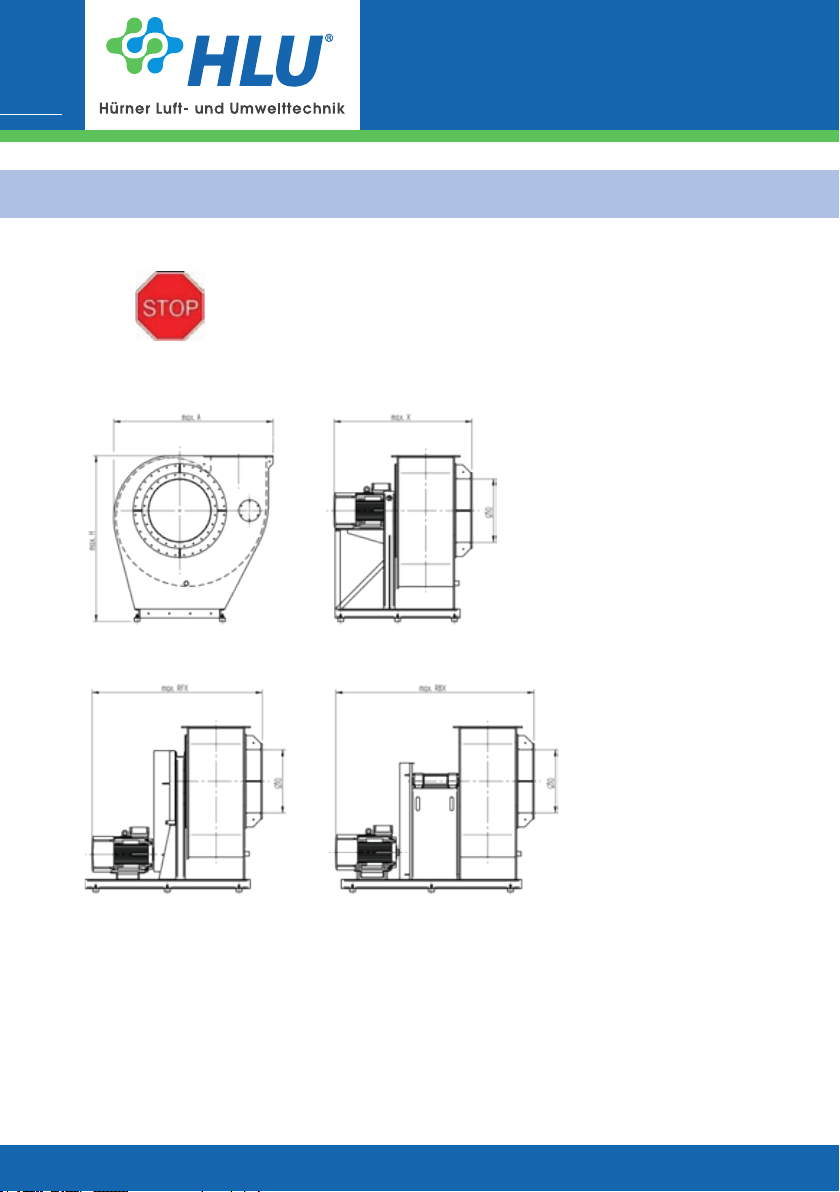
Fig. 2a| Overview of the fan HF R | Direct drive
Fig. 2b| Overview of the fan HF R | Belt drive:
Belt ange bearing (RF) and Belt block bearing (RB)
www.hlu.eu
Page 13
Operating manual
Centrifugal fans
HF R | RV | MRV
13
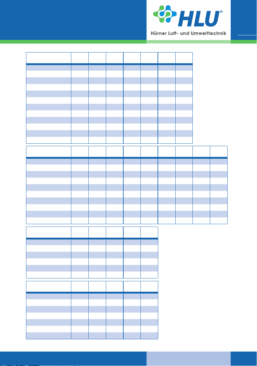
Type ØD
HF R 125-15/17 125 366,5 435 504 12
HF R 140-15/17 140 409 462 518 13
HF R 160-15/17 160 464 861,5 725 91 880 99
HF R 180-15/17 180 522 558 629 27 760 28
HF R 200-15/17 200 582 945 812 110 1037 166
HF R 250-15/17 250 732 1040 925 129 1080 174
HF R 280-15/17 280 816 804 768 62 923 56
HF R 315-15/17 315 920,5 1290 1179 260 1334 351
HF R 355-15/17 355 1030 1426 1151 214 1412 352
HF R 400-15/17 400 1141 1562 1255 280 1451 402
HF R 450-15/17 450 1297 1625 1320 310 1546 552
HF R 500-15/17 500 1469 1811 1378 506 1575 691
Type ØD
HF R 450-13 450 1200 1250 1550 1950
HF R 500-13 500 1350 1400 1650 2050
HF R 560-13 560 1575 1860 1471 600 1836 650 2110 750
HF R 630-13 630 1770 2065 1635 950 1965 1000 2155 800
HF R 710-13 710 1985 2310 1710 1150 2040 1200 2405 1200
HF R 800-13 800 2235 2470 1889 1350 2249 1450 2700 1500
HF R 900-13 900 2515 2750 2223 1850 2583 1950 2895 2000
HF R 1000-13 1000 2780 3060 2343 2596 2813 2200 3220 2300
HF R 1120-13 1120 2942 3500 2621 3298 3106 2350 3410 3500
HF R 1250-13 1250 3105 3840 2900 4000 3400 4300 3600 4700
Type ØD
HF R 160-16 160 459 750 850 33
HF R 200-16 200 582 730 1020 41
HF R 250-16 250 710 775 1150 58
HF R 315-16 315 893 965 1350 81
HF R 355-16 355 1008 1090 1450 98
HF R 400-16 400 1126 1250 1450 149
Type ØD
HF R 50-48 50 372 605 622 85
HF R 63-48 63 455 640 633 100
HF R 80-48 80 566 705 719 150
HF R 100-48 100 703 805 781 200
HF R 125-48 125 860 950 929 300
HF R 160-48 160 1100 1180 1021 400
HF R 200-48 200 1353 1390 1215 550
max. Amax. Hmax. Xmax.
max. Amax. Hmax. Xmax.
max. Amax. Hmax.
RFX
max. Amax. Hmax.
RFX
kg.
kg.
max.
kg
max.
kg
max.
RFX
max.
RFX
max.
kg
max. kgmax.
RBX
max.
kg
Dimensions and design can be changed | Dimensions in mm
www.hlu.eu
06.2019
Page 14
14
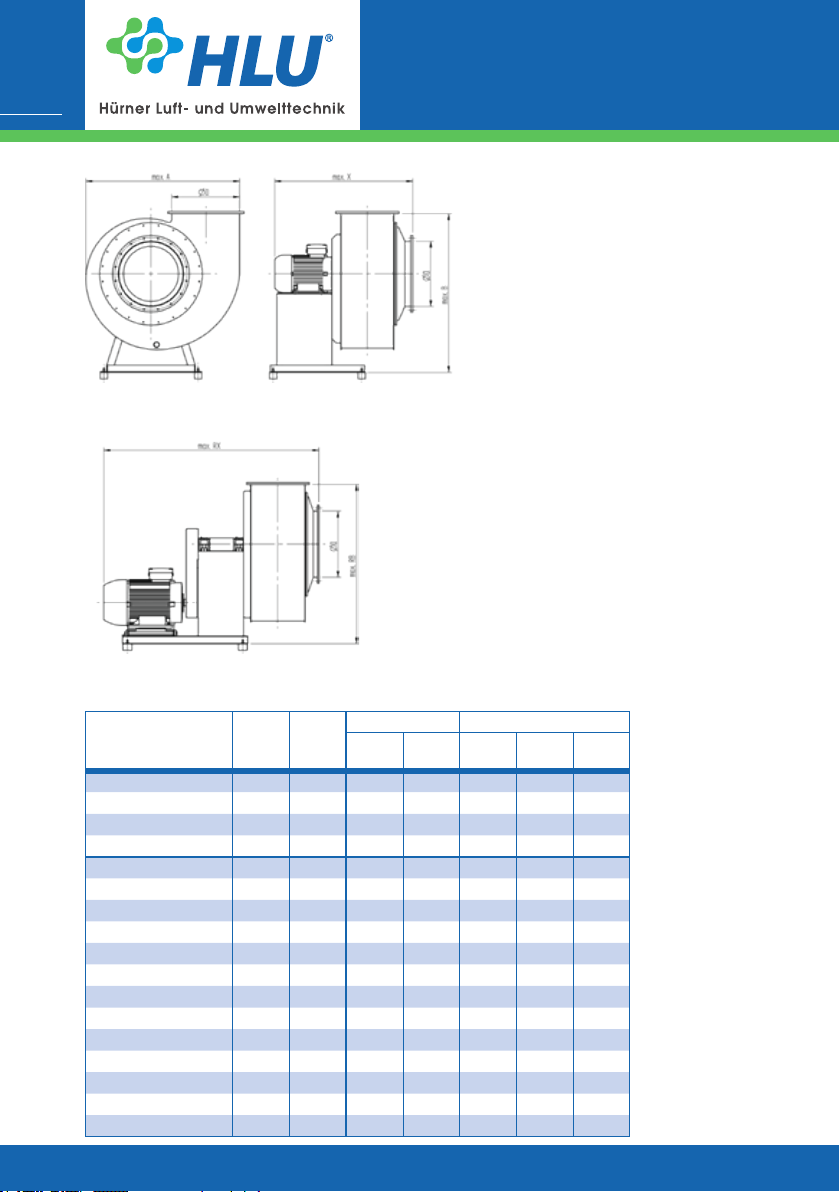
Fig. 2c| Overview of the fan RV / MRV | Direct drive
Operating manual
Centrifugal fans
HF R | RV | MRV
06.2019
Fig. 2d| Overview of the fan RV / MRV | Belt drive
Direct drive Belt drive
max.
Type ØD
RV 20-80 80 400 550 500 600 850
RV 20-100 100 500 600 500 650 900
RV 20-125 125 600 750 550 800 1250
RV 20-140 140 700 800 550 800 1300
RV 28-200 200 600 700 600 700 1000 53
RV 28-225 225 650 750 650 700 1050 40
RV 28-250 250 700 800 650 750 1050 46
RV 28-280 280 800 900 950 850 1350
RV 28-315 315 900 950 1000 900 1400 80
RV 28-355 355 1000 1200 1000 1100 1850
RV 28-400 400 1100 1250 1050 1150 1850 180
RV 28-450 450 1250 1500 1250 1350 1950
RV 28-500 500 1400 1550 1300 1400 1950
RV 28-560 560 1550 1600 1400 1700 2150
RV 28-630 630 1700 1800 1550 1750 2250 380
RV 28-710 710 1900 2100 2050 2100 2700
RV 28-800 800 2150 2250 2150 2250 2800
max. Bmax. Xmax. RBmax. RXmax.
A
kg
www.hlu.eu
Page 15
Operating manual
Centrifugal fans
HF R | RV | MRV
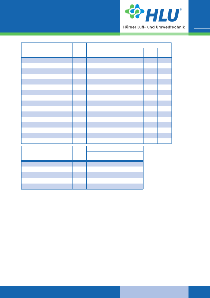
Direct drive Belt drive
max.
Type ØD
RV 45/63-160 160 400 500 500 6 550 950 22
RV 45/63-200 200 500 600 550 9 600 1000 23
RV 45/63-250 250 650 750 680 15 700 1100 32
RV 45/63-315 315 800 900 720 25 850 1300 46
RV 45/63-355 355 900 950 780 30 900 1450 55
RV 45/63-400 400 1000 1100 1100 65 1100 1850 120
RV 45/63-450 450 1100 1150 1150 125 1150 1850 150
RV 45/63-500 500 1200 1350 1300 95 1350 2000 200
RV 45/63-560 560 1350 1400 1350 170 1400 2000 150
RV 45/63-630 630 1500 1700 1500 265 1700 2250 355
RV 45/63-710 710 1700 1750 1650 1750 2350
RV 45/63-800 800 1900 2100 2100 480 2100 2850 560
RV 45/63-900 900 2150 2200 2200 2200 2950
RV 45/63-1000 1000 2400 2650 2300 720 2650 3150 1000
RV 45/63-1120 1120 2700 2750 2450 2750 3300 1040
RV 45/63-1250 1250 3000 3050 2550 3050 3500
Type ØD
MRV 45/63-160 160 450 600 550 650 950
MRV 45/63-200 200 550 750 600 750 1000
MRV 45/63-250 250 650 900 700 850 1100
MRV 45/63-315 315 800 1100 1000 1050 1300
MRV 45/63-355 355 850 1150 1050 1100 1450
max. Bmax. Xmax.
A
Direct drive Belt drive
max.
max. Bmax. Xmax. RBmax.
A
max. RBmax. RXmax.
kg.
RX
kg
15
Dimensions and design can be changed | Dimensions in mm
3.1 General data
Ambient temperature range
The specications on the type label are applicable. If they are missing, the temperature range
is - 20 °C to + 40 °C.
Noise level
For the value applicable to each fan, see the manufacturer internet site, or contact us via phone.
Others
More relevant data are given on the type label.
The service life of bearing is depending on the load at > 25 000 h.
www.hlu.eu
06.2019
Page 16
Operating manual
Centrifugal fans
16
3.2 Power supply (see motor type label)
Optionally, the electric motors can be controlled continuously by means of a frequency inverter.
The maximal rotation speed at the impeller (see fan type label) must not be exceeded.
The ICA (instrumentation technology, control technology, automation technology) on site must
give protection against overspeed according DIN EN 60204-1.
In case of operation of several motors with a frequency inverter all-pole sinusoidal lters should
be used between frequency inverter and motor.
If frequency inverters are used in the explosion-hazarded area (Zone 1) these must be installed
outside the explosion-hazarded area and ameproof motors to DIN EN 60079-1 must be used.
Before connecting the fan, check the specications on the type label
and dimension the electrical control system accordingly.
With a motor power ≥ 4 kW for starting up the fan is a star-delta-connection, a soft starter or a FI regulation to use to protect the impeller
and the motor bearing against premature damages.
In the case of direct involvement or frequent restart, damage or increased wear may arise by the torque forces on the impeller.
4. Safety
HF R | RV | MRV
06.2019
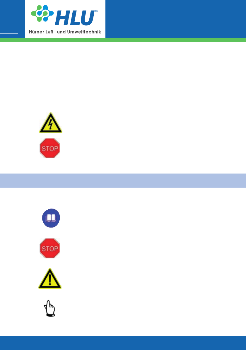
4.1 Signs and explanations
The information given in the operating manual is binding
is marked with a „book“.
Warnings
are marked with a „STOP“ sign.
Danger warnings
are marked with a warning triangle.
Notes
are marked with a hand symbol.
www.hlu.eu
Page 17
4.2 Fan marking
Operating manual
Centrifugal fans
HF R | RV | MRV
Hazards due to electric current
are marked with the symbol shown opposite.
Protective earth connection
is marked by these symbols at the connecting points.
Hazards due to explosive atmosphere
are marked with the symbol shown opposite.
17
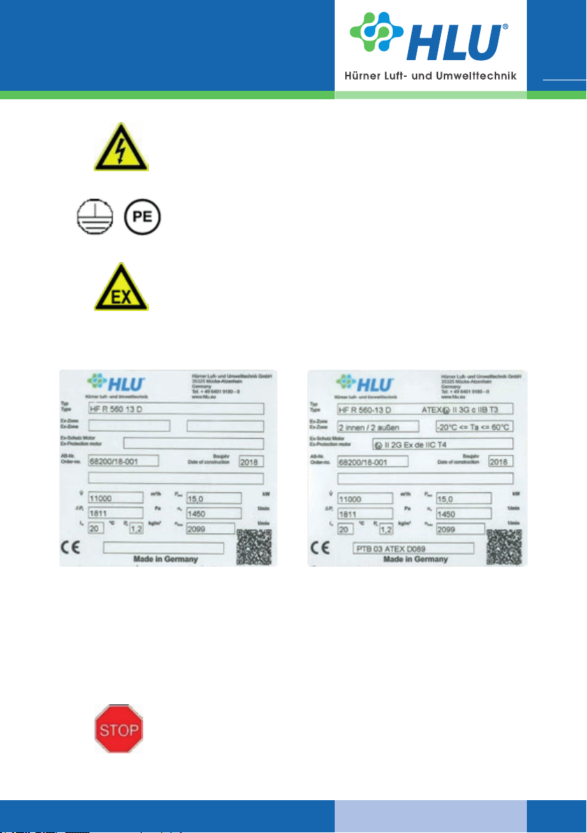
Specications for fans without explosion protection:
Type
Order no. (AB) Construction year
Fan-specic data
Fig. 3a| Type label (normal application)
Caution
Fans without explosion protection marking are not permissible for
operation inside the explosion-hazarded atmosphere.
This applies to the environment and the exhausted uid.
www.hlu.eu
Specications for fans with explosion protection:
Type Denomination of explosion
protection type
Ex-Zone Temperature
Motor explosion protection type
Order no. (AB) Construction year
Fan-specic data
Fig. 3b| Type label (explosive atmosphere)
06.2019
Page 18
Operating manual
Centrifugal fans
18
Meaning of possible device categories on the type label:
II 2G
II 2/3G
II 3G
II 3/-G
The information given in these operating instructions is only applicable to the fan type specied
on the title page. The type label with the type denomination is located on the base frame or on
the side panel of the fan housing. With all enquiries, make sure to specify the order conrmation
no. and the type label properly to ensure correct and quick handling.
The fan is suitable for exhaustion from zone 1
and for installation in zone 1
The fan is suitable for exhaustion from zone 1
and for installation in zone 2
The fan is suitable for exhaustion from zone 2
and for installation in zone 2
The fan is suitable for exhaustion from zone 2
and must be installed outside the hazardous area
4.3 Built-in safety systems (to be implemented by the user)
The built-in safety devices must be checked at regular intervals:
d = daily, w = weekly, m = monthly, j = yearly.
The following methods must be used for checking:
V = visual check, F = functional check, M = measurement.
Overcurrent protection device
To prevent overheating (re hazard) in the event of overload (e.g. due
to clogging), the fan drive has to be provided with an overcurrent protection device.
HF R | RV | MRV
Check
Interval Method
y F
06.2019
Thermal contact (optional)
For temperature monitoring, the fan is equipped with a thermal
contact. In the event of a temperature increase, the motor switches
o.
PTC resistor (optional)
Don‘t connect the PTC resistor to the mains voltage. Avoid exceeding
a max. PTC resistor test voltage of 2.5 V.
Protective claddings
All mobile fan components driven by the electric motor as well as all
other hazardous parts of the fan are covered by xed, safely fastened
protective claddings that can be removed only using tools.
Electrical connection
The electrical connections are made using a 4-wire supply cable system, 3 phases and 1 earth conductor with three-phase motors and
using a 3-wire supply cable system, 1 phase, 1 neutral wire and 1
earth conductor with alternating current motors.
Check
Interval Method
y F
Check
Interval Method
y F
Check
Interval Method
m V
Check
Interval Method
y V, F, M
www.hlu.eu
Page 19

Operating manual
Centrifugal fans
HF R | RV | MRV
Deactivating the safety devices, or changing their operating principle,
is strictly prohibited.
4.4 Interfaces of the fan
The fan has the following interfaces:
J Outlet side (connection via sleeve with tightening strap or ange)
J Terminal box or maintenance switch (electric supply)
J Inlet side (connection via sleeve with tightening strap or ange)
4.5 Safety measures (to be implemented by the user)
We point out that the user is under the duty to:
J instruct the operating and maintenance personnel on the protective devices of the fan,
J and to ensure supervision concerning compliance with the safety measures.
This operating manual must be kept for future use. The specied frequency of inspection and
control measures must be met.
J The chapters related to transport, installation and mounting, maintenance, troubles/causes/
troubleshooting must be understood by a qualied person. Work described in this chapter
may be performed only by qualied personnel.
19
4.6 User‘s responsibilities
In the European Economic Area, compliance with Council Directive
(89/391/EEC) and the related individual directives, especially Council
Directive 89/655/EEC Concerning the Minimum Safety and Health
Requirements for the Use of Work Equipment by Workers at Work in
the relevant national version is mandatory.
The user must obtain the local operating licence and follow the relevant rules.
Additionally, the user must ensure compliance with the national legal regulations concerning
J the personnel safety (regulations relating to accident prevention)
J the safety of work equipment (protective equipment and maintenance)
J product recycling (Waste Management Law)
J material disposal (Waste Management Law)
J cleaning (cleaning agents and disposal)
J and comply with the requirements for environment protection.
www.hlu.eu
06.2019
Page 20
Operating manual
Centrifugal fans
20
To avoid the occurrence of ignition sources, the operating and maintenance personnel must be equipped properly and receive adequate
instructions for realization of cleaning and maintenance work, e.g.
J to avoid the use of tools giving rise to sparking,
J strict observance of the smoking ban,
J to avoid the actuation of ignition sources (e.g. lighters, etc.).
5. General warning symbols
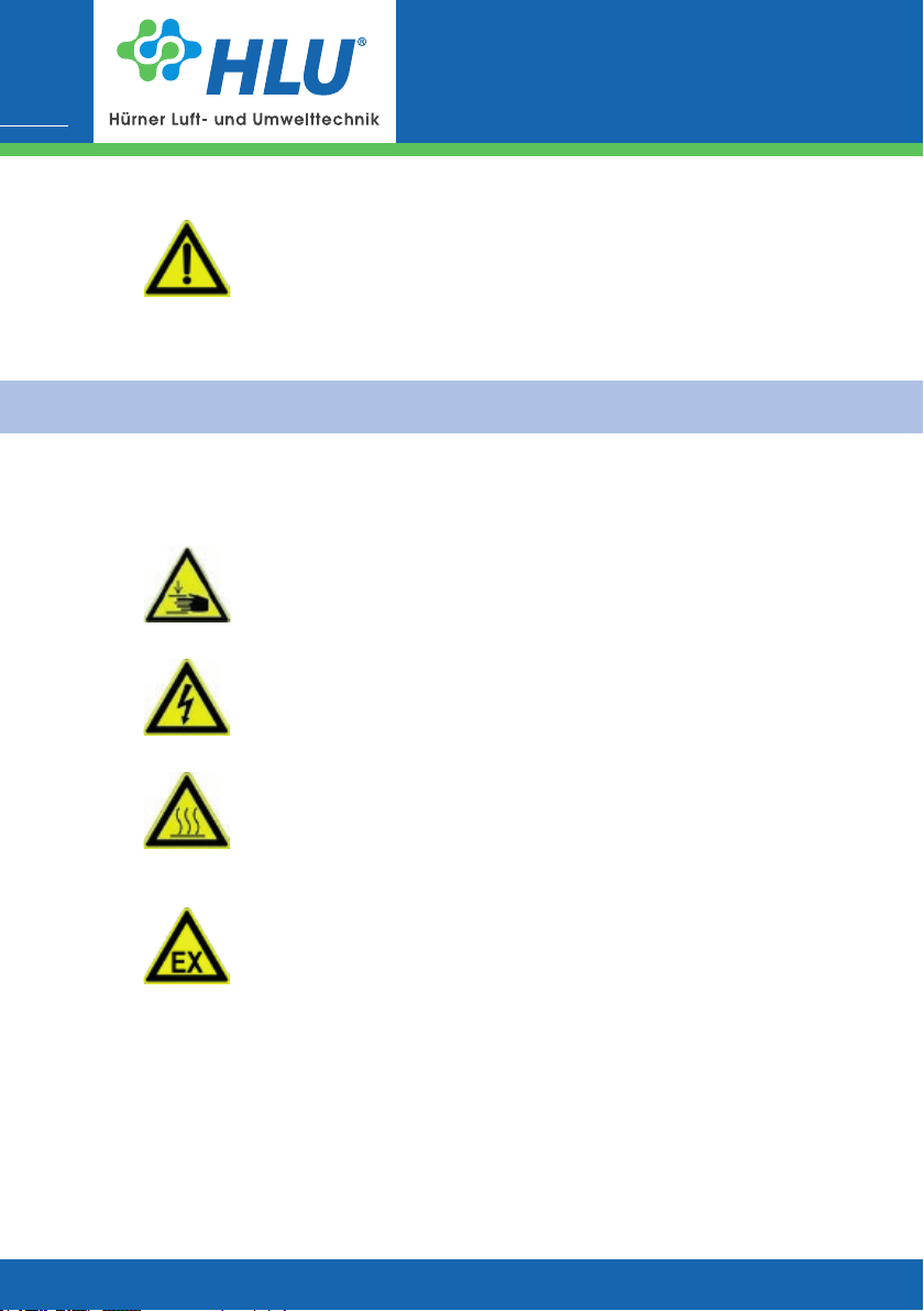
5.1 Hazards
Pay attention to the safety devices described in this manual and follow the safety notes.
During setup, maintenance and repair work, mind the squeezing
hazards.
During setup, maintenance and repair work, mind the hazard due to
electric current!
HF R | RV | MRV
06.2019
During setup, maintenance and repair work, be aware of the risk of
getting burned due to hot components.
In the event of a failure of the forced ventilation, the drive motor presents a hazard of getting burned.
When doing setup, maintenance and repair work within the explosion-hazarded area, make sure that there isn‘t a critical gas
concentration. Use a gas detector. Always avoid handling all kinds of
ignition sources inside the explosion-hazarded area. Welding, cutting
and polishing work may be performed only, if the related permission
was granted.
5.2 Operating and hazardous areas on the fan
Hazardous area
During setup, maintenance and repair work, the overall area around the fan is a hazardous
area.
www.hlu.eu
Page 21

Operating manual
Centrifugal fans
HF R | RV | MRV
During maintenance and repair work, the hazardous area extends 1 m
around the fan. The ap pivoting area must be taken into account as
well. Keep the area around the fan free from any objects.
5.3 Installation of spare and wear parts
We point out explicitly that spare parts and accessories not supplied by us are not checked and
released for use by us either. Installation and/or use of these products can change the design
properties of your fan negatively.
The manufacturer cannot be held responsible for damage resulting from the use of other than
original components. In connection with the order conrmation, you will receive a data card and
a spare parts list for the fan.
If you need spare parts, please, inform our sales partner:
21
Hürner Luft- und Umwelttechnik
Ernst-Hürner-Straße
35325 Mücke-Atzenhain
Germany
Tel.
Fax
E-Mail
For Asien: Hürner Funken Malaysia Sdn. Bhd.
Lot 3, Milon Industrial Park
Jalan Minlon Utama o Jalan Taming 2
Taming Jaya, 43300 Balakong
Selangor DE
Malaysia
Tel.
Fax
When ordering spare parts, please specify the following data:
J Order no. (see type label)
J Fan type
J Spare part denomination
+ 49 6401 9180 - 0
+ 49 6401 9180 - 142
[email protected]
www.hlu.eu
+ 603 8961 9863
+ 603 8961 9862
www.huerner-funken.com.my
HLU Systemtechnik
Sälzerstraße 20a
56235 Ransbach-Baumbach
Germany
Tel.
Fax
E-Mail
+ 49 2623 92 95 9 - 0
+ 49 2623 92 95 9 - 99
[email protected]
www.hlu.eu
www.hlu.eu
06.2019
Page 22

Operating manual
Centrifugal fans
22
6. Installation
6.1 Scope of supplies
The equipment delivered to the user comprises:
J Centrifugal fan
J Operating manual
J Technical documents
For the detailed scope of equipment supplied, refer to the order conrmation.
6.2 Transport and packing
Although the fans are checked and packed carefully before shipment, damage during transport
cannot be excluded.
6.3 Delivery (also with spare and substitute parts)
Inspection of incoming components:
J Check, if the consignment is complete according to the bill of delivery.
HF R | RV | MRV
06.2019
In the event of damage
J Check the consignment for damage (visual inspection).
In the event of complaints
If the consignment was damaged during transport:
J Contact the last forwarder immediately.
J Keep the packaging (for checking by the forwarder or for returning the product).
Packaging for returning the product
J If possible, use the original packaging and the original packaging material. If the original
packaging and packaging material haven‘t been kept, use commercial packaging material.
Fasten the fan to a transport pallet (it must be dimensioned appropriately for the weight).
J With any questions relating to packaging and safe transport, please, consult the manufac-
turer.
6.4 Intermediate storage
The fans should be stored in a room or under a shelter. With outdoor storage, protect the
fan from dirt and atmospheric conditions using a canvas cover. Keep the storage temperature
between 0 °C and + 40 °C.
To avoid permanent deformation by preventing static load at the contact points between the
rolling elements and bearing raceways, the impeller has to be turned for a ¼ turn at regular
intervals (at least every 4 weeks).
www.hlu.eu
Page 23
Operating manual
Centrifugal fans
HF R | RV | MRV
With belt-driven fans, note that the V-belts must be released in case of prolonged storage periods or standstill ( > 4 weeks ), in order to prevent damage of bearings and V-belts.
6.5 Transport to the place of installation (at the customer‘s site)
Transport must be performed only by qualied personnel in compliance with the local conditions and any warning notes on the packaging
material.
The fan or fan unit is transported on transport pallets to the site.
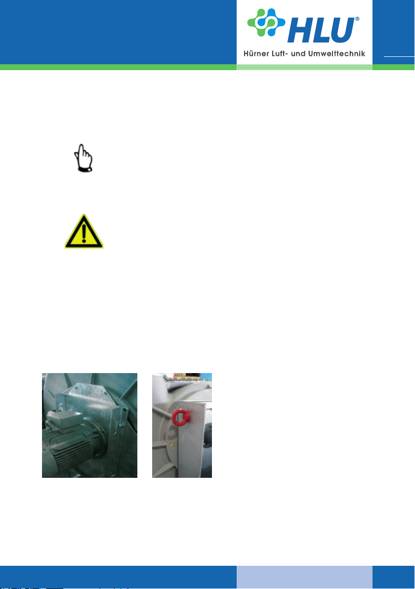
The fan or transport unit may tip over during transport.
Pay attention to the focus (the focus is centred) and weight (see
technical data).
Secure the fan or the transport unit with appropriated resources
before the transport.
Transport with forklift
J The forklift has to be adjusted according to the weight of the fan or the transport unit.
J Drive with the forks of the forklift between or under the arbors of the transport pallet of the
fan or the transport unit.
J Make sure that the forks of the forklift are completely under the arbor (the forks have to look
out at the opposite).
J Lift the fan or transport unit and transport it.
23
Weight see cap. 3.
Transport of the fan to the site
Fig. 4| Transport of the fan to the site
www.hlu.eu
The fan has to be transported with appropriated resources at the designated points
and it has to be secured against overturning.
Attention: The focus must be on the bottom!
The lifting and transporting of the fans can
be done manually depending on the size
and the weight.
06.2019
Page 24

Operating manual
Centrifugal fans
24
6.6 Installation, mounting, Initial commissioning
Installation, mounting and initial commissioning of the fan are performed by qualied personnel
of manufacturer or by qualied customer personnel that must have been trained adequately
for this work.
J The constructional arrangement of the fan must ensure that operational underpressure con-
ditions are present at the shaft passage.
J Check on the basis of the static of the building, if it is adjustable for the burden of the fan
and if the bottom is at.
J The installation of the fans and their components are based on the on-site installation plan.
J The fan must be mounted on vibration dampers. The Vibration absorbers used for instal-
lation of the fan must be mounted by means of screws in the marked and readily drilled
positions in the foundation frame and fastened with bolts in the on-site foundation.
J We recommend a circumferential distance of approx. 1.5 m to 2 m, for maintenance work at
the fan.
For maintenance work at the inlet side oft the fan, the housing cover should be removed if
necessary. Therefore we advise mounting a removable pipe section of approx. 1 m in front
of the fan if the fan cannot be postpone.
J The fan must not be operated in non-installed condition. The impeller must be free to move
without any impediment at all times.
J Mount the (on-site) pipe.
J The fan is equipped with a terminal box (or maintenance switch) for connecting to the mains
supply. The motor enclosure must be closed using a sealing joint certied according to
the EN IEC 60079-0 and EN IEC 60079-1 standards. Users will have to connect the cable
terminals using one of the protection types specied in standard EN 60079-0. The energy
supply can be cut o using an onsite maintenance switch (if it is not already installed at the
fan).
J Check before the rst operation that the turning direction is correct (direction arrow on the
fan housing) and that the max. speed is not exceeded (see nameplate).
J If there is danger of foreign parts falling into the fan or being aspirated, the connected pipe
upstream and downstream of the fan must be provided with a protective grid (min. IP20 to
EN 60529).
J The motors are designed for a maximum ambient temperature of 40 °C. Ventilation must not
be impaired. The minimum distance between fan housing and adjacent objects must be ¼
of the diameter of the ared fan housing bezel.
J If the fan shall be installed outdoor, we recommend a protection of the drive motor against
water.
J The inside of the fan and of upstream and downstream channels and units must be keptfree
from foreign bodies.
J After a run-in period of 1 or 2 hours check the drive at regular intervals and re-tighten the
belts, if necessary.
J The condensate drain at the bottommost point of the housing has to be connected.
J See point 3.2.
J Ensure that connected lines do not carry loads which lead to a distortion of the fan housing.
HF R | RV | MRV
06.2019
www.hlu.eu
Page 25
Operating manual
Centrifugal fans
HF R | RV | MRV
The fan may be connected to the supply voltage and switched on
only, when the pipe (on the inlet and outlet side) has been connected
completely.
Installation must be performed according to the connecting diagram in
the motor operating instructions only by adequately trained and qua-
lied personnel.
The following conditions must be met:
J Compliance with the national regulations relating to the public utilities.
J The supply voltage at the place of installation and the mains frequency must correspond to
the values specied on the motor type label.
J The power supply cable must be protected against damage and dimensioned adequately
for the power rating.
J Set the thermal overcurrent relay to the nominal current specied on the motor type label
and follow the instructions given in the motor operating instructions. We reserve ourselves
the right to cancel the motor warranty in the event of failure to comply with this protective
measure.
Make sure that the rotating direction is correct. To check the rotating
direction, switch on the motor shortly and compare the impeller rotating direction with the arrow marked on the housing. If the rotating
direction is wrong, change the motor polarity in compliance with the
safety regulations. After reaching the operating speed, measure the
power consumption immediately and compare it to the motor current
specied on the type label.
25
24 h after initial commissioning: Check the tightness of the housing
and the quiet run of the fan and re-tighten the screws.
Caution
The fan pipe connections may be performed only using exible couplings (compensators).
6.7 Operating modes
The fan is switched on and o via an on-site operating unit provided by the user, or operated via
an on-site supervisory system. It is designed for continuous operation.
www.hlu.eu
06.2019
Page 26
Operating manual
Centrifugal fans
26
7. Operation
The fan may be operated only by specialized personnel qualied and
trained for operation.
8. Maintenance / Cleaning
The chapter on „Maintenance / Cleaning“ is intended only for
qualied personnel. Maintenance, cleaning and repair work may be
performed only by qualied personnel.
Qualied person
A person who is able to assess the work he/she is in charge of and aware of potential hazards
due to his/her professional training, skills and experience as well as his/her knowledge of the
relevant standards.
Denition according to EN 60204-1.
To ensure smooth operation of the fan, cleaning and maintenance of the fan at regular intervals
is required.
During operation, the fan is subject to vibration susceptible of releasing screwed and clamping
connections. To prevent damage, check the fan for loosened connections at regular intervals
(recommended interval with single-shift operation: 3 months).
HF R | RV | MRV
06.2019
For information on maintenance/cleaning of individual components
purchased from other manufacturers (e.g. electric motor), refer to the
corresponding manufacturer operating instructions.
When switching o the supply voltage because of cleaning, maintenance and repair work, measures to prevent the supply voltage from
being switched on accidentally must be taken by the user (locking the
main or maintenance switch using a padlock).
During maintenance and repair work, mind all rotating and mobile
parts. Risk of entanglement! Tight clothing must be worn in the danger area.
During maintenance and repair work, mind the squeezing hazards.
www.hlu.eu
Page 27
8.1 Cleaning
Operating manual
Centrifugal fans
HF R | RV | MRV
When doing maintenance and repair work, mind the hazards due to
electric current.
Cleaning, maintenance and repair work may be done only at
non-explosive atmosphere.
For reasons of safety, only tools made of non-sparking material may
be used when doing this work.
The work intervals specied below are intended for single-shift operation (8 hours a day; 22 days a month; 12 months a year).
d
= daily
w
= weekly
m
= monthly
½ y
= half-yearly
Don‘t use any sharp objects or tools for cleaning. Only objects that are
explicitly provided for this purpose are suitable.
y
= yearly
R
= cleaning required when opening
LT
= lifetime
MO
= manufacturer operating manual
27
(Depending to the degree of contamination the cleaning intervals
Cleaning
must be adapted) Interval
Keep the fan and the area around the fan free from deposits on the outside regu-
larly (e.g. dust, exhaust uids).
Check the impeller regularly for contaminations and cakings and clean it, if
necessary.
Caution
Contaminations on the impeller can cause imbalance of the fan.
Depending on the intensity, this can even cause the destruction of the fan.
Make sure that the cooling ns of the electric motor are not clogged by pollution in
order to avoid overheating, if necessary clean them.
Caution
When doing cleaning work, wear protective equipment in compliance with the operational regulations for occupational health and safety
(e.g. protective gloves).
www.hlu.eu
w
½ y
m
06.2019
Page 28
Operating manual
Centrifugal fans
28
8.2 Lubrication
The lubrication points of the fans have to be greased regularly using appropriated lubrication
tools. The lubrication periods depend on the operating hours of the fan (see next schedule).
J The bearings of the installed maintenance-free electric motors have a grease lling, which
is calculated for a service life of approx. 10.000 - 20.000 operating hours. The maintenan-
ce-free ange double bearings (299 T ...W, 399 T ...W), were lled with grease suciently
by the manufacturers, this means they have a calculated service life of approx. 20000 operating hours.
J The periods and amount of the lubrication on the electric motor and regreasable double
ange bearings 399T…N and block bearing 32T…ER depend on the operating hours of the
fan. After max. 8000 operating hours at the latest after one year of operation the bearings
have to be greased again according to the next schedule.
J We recommend as appropriated bearing grease a lithium soap grease, for example Shell-Al-
vania 2 or 3. The determined lubrication intervals are applicable to bearings in horizontal
mounting position at a maximum temperature of 70 °C. As lubricant aging is accelerated
at higher temperatures, the lubrication interval must be reduced by half with a temperature
increase of 15 °C.
J Concerning the lubrication intervals of electric motors please note the operating and main-
tenance instructions of the engine producer.
Details about the kind, amount and period of lubrication of the single
purchase component devices have to be taken from the external manufacturer’s operating manual.
HF R | RV | MRV
06.2019
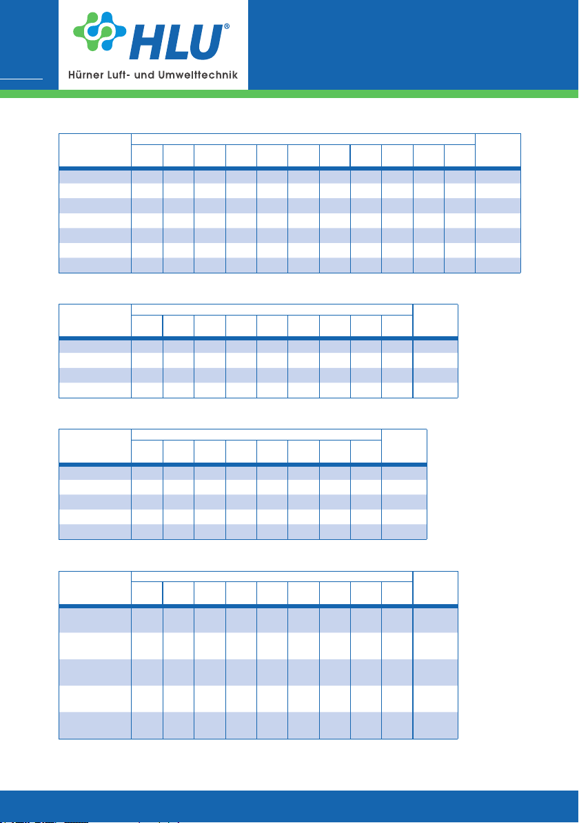
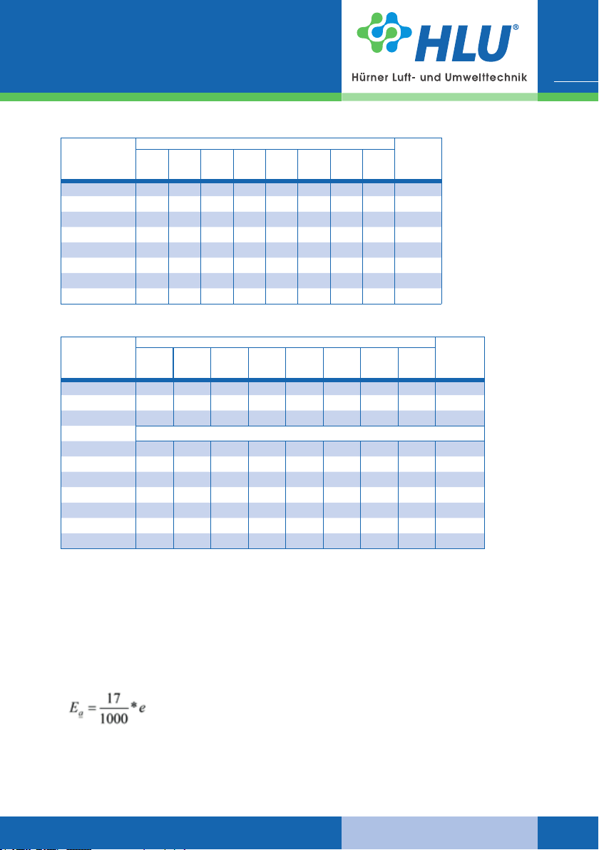
Greasing periods depending on the speed and nominal size of the fan:
HF R ...-15 / 17 D / R
Only the fan type HF R 250-17 R with a speed over 2000 min-1 has got a regreasable bearing
installed.
Nominal fan
size
HF R 250-17
Speed fan
2000
2500
min-1
3000
min-1
min-1
8000 h 7000 h 5500 h 4500 h
3500
min-1
Quantity
of grea-
sing
8 g
www.hlu.eu
Page 29
HF R ...-13 D / R
Nominal fan
size
HF R 450-13 RB
HF R 500-13 RB
HF R 560-13 RB
HF R 630-13 RB
HF R 710-13 RB
HF R 800-13 RB
HF R 900-13 RB
HF R 1000-13 RB
HF R 1120-13 RB
HF R 1250-13 RB
Operating manual
Centrifugal fans
HF R | RV | MRV
500
750
min-1
min-1
8000 h 8000 h 8000 h 7000 h
8000 h 8000 h 8000 h 8000 h
8000 h 8000 h 8000 h 8000 h
8000 h 8000 h 8000 h 7500 h
8000 h 8000 h 8000 h
8000 h 8000 h 8000 h
Speed fan
1000
1500
2000
min-1
min-1
8000 h 8000 h 8000 h 6000 h 5000 h
8000 h 8000 h 8000 h 6000 h
8000 h 8000 h 7000 h 5000 h
8000 h 8000 h 7000 h
min-1
2500
min-1
3000
min-1
Quantity
of grea-
sing
10 g
10 g
15 g
15 g
15 g
20 g
26 g
33 g
33 g
42 g
29
Nominal fan
size
HF R 450-13 RF
HF R 500-13 RF
HF R 560-13 RF
HF R 630-13 RF
HF R 710-13 RF
HF R 800-13 RF
HF R 900-13 RF
HF R 1000-13 RF
HF R ...-16 R
Nominal fan
size
HF R 160-16 R
HF R 200-16 R
HF R 250-16 R
HF R 315-16 R
HF R 355-16 R
HF R 400-16 R
750
min-1
2500
min-1
Speed fan
1000
1500
min-1
min-1
3000
3500
min-1
min-1
2000
min-1
4000
min-1
500
min-1
13000 h 10000 h 2000 h 1500 h
13000 h 10000 h 7000 h 5000 h
4000 h 2200 h 1500 h 1000 h
4000 h 2200 h 7000 h 5000 h
3800 h 2200 h 7000 h 4500 h
17500 h 14000 h 10000 h 8000 h
17500 h 14000 h 10000 h 8000 h
16000 h 13000 h 10000 h 8000 h
2000
min-1
8000 h 8000 h 7000 h 6000 h 4800 h 4000 h 3500 h 3000 h 2750 h 2350 h 2000 h
8000 h 8000 h 7000 h 6000 h 4800 h 4000 h 3500 h 3000 h 2750 h
8000 h 7000 h 5500 h 4500 h 3200 h 2700 h 2000 h
7000 h 5000 h 4000 h 3000 h
7000 h 5000 h 4000 h 3000 h
7000 h 5000 h 4000 h 3000 h
2500
min-1
Speed fan
4500
min-1
Quantity
of grea-
sing
10 g
13 g
13 g
21 g
21 g
21 g
21 g
21 g
5000
min-1
5500
min-1
6000
min-1
6500
min-1
7000
min-1
Quantity
of grea-
sing
5 g
5 g
7 g
9 g
9 g
9 g
www.hlu.eu
06.2019
Page 30
30
HF R ...-48 R
Nominal fan
size
HF R 48-50
HF R 48-63
HF R 48-80
HF R 48-100
HF R 48-125
HF R 48-160
HF R 48-200
RV 20-... R | up to size 355
Nominal fan
size
RV 20-80 R
RV 20-100 R
RV 20-125 R
RV 20-140 R
RV 28-... R | up to size 355
Nominal fan
size
RV 28-200 R
RV 28-225 R
RV 28-250 R
RV 28-280 R
RV 28-315 R
Operating manual
Centrifugal fans
HF R | RV | MRV
2000
2500
3000
3500
4000
min-1
min-1
min-1
min-1
8000 h 8000 h 7000 h 6000 h 4800 h 4000 h 3500 h 3000 h 2750 h 2350 h 2000 h
8000 h 8000 h 7000 h 6000 h 4800 h 4000 h 3500 h 3000 h 2750 h
8000 h 7000 h 5500 h 4500 h 3200 h 2700 h 2000 h
7000 h 5000 h 4000 h 3000 h
7000 h 5000 h 4000 h
6500 h 4500 h 3000 h
6500 h
1000
1500
min-1
2000
min-1
min-1
8000 h 8000 h 8000 h 7500 h 6000 h 5000 h 4000 h 3500 h
8000 h 8000 h 8000 h 7500 h 6000 h 5000 h 4000 h 3500 h
8000 h 8000 h 8000 h 6500 h 5000 h 4000 h 3000 h 2500 h
8000 h 8000 h 8000 h 6500 h 5000 h 4000 h 3000 h 2500 h
2500
min-1
Speed fan
min-1
3000
min-1
4500
min-1
3500
min-1
Speed fan
1500
2000
2500
3000
3500
Speed fan
min-1
min-1
min-1
min-1
8000 h 8000 h 8000 h 8000 h 7000 h 6000 h 5000 h 4500 h
8000 h 8000 h 8000 h 8000 h 7000 h 6000 h 5000 h 4500 h
8000 h 8000 h 8000 h 8000 h 7000 h 6000 h 5000 h 4500 h
8000 h 8000 h 8000 h 8000 h 7000 h 6000 h 5000 h 4500 h
8000 h 8000 h 8000 h 8000 h 7000 h 6000 h 5000 h 4500 h
min-1
4000
min-1
5000
min-1
4000
min-1
4500
min-1
5500
min-1
4500
min-1
5000
min-1
6000
min-1
5000
min-1
Quantity
of grea-
sing
9 g
9 g
9 g
9 g
9 g
6500
min-1
Quantity
of grea-
sing
6 g
6 g
9 g
9 g
7000
min-1
Quantity
of grea-
sing
5 g
5 g
7 g
9 g
9 g
12 g
12 g
06.2019
RV / MRV 45/63-... R | up to size 355
Nominal fan
size
RV / MRV
45/63-160 R
RV / MRV
45/63-200 R
RV / MRV
45/63-250 R
RV / MRV
45/63-315 R
RV / MRV
45/63-355 R
1000
1500
min-1
2000
min-1
min-1
8000 h 8000 h 8000 h 8000 h 8000 h 8000 h 7000 h 6500 h
8000 h 8000 h 8000 h 8000 h 8000 h 8000 h 7000 h 6500 h
8000 h 8000 h 8000 h 8000 h 8000 h 8000 h 7000 h 6500 h
8000 h 8000 h 8000 h 8000 h 8000 h 7000 h 6000 h
8000 h 8000 h 8000 h 8000 h 8000 h 7000 h 6000 h
2500
min-1
Speed fan
3000
min-1
3500
min-1
4000
min-1
4500
min-1
5000
min-1
Quantity
of grea-
sing
6 g
6 g
6 g
9 g
9 g
www.hlu.eu
Page 31
Operating manual
RV 28-... R | up to size 355
Nominal fan
size
RV 28-355 R
RV 28-400 R
RV 28-450 R
RV 28-500 R
RV 28-560 R
RV 28-630 R
RV 28-710 R
RV 28-800 R
RV 45/63-... R | up to size 355
Nominal fan
size
RV 45/63-400 R
RV 45/63-450 R
RV 45/63-500 R
RV 45/63-560 R
RV 45/63-630 R
RV 45/63-710 R
RV 45/63-800 R
RV 45/63-900 R
RV 45/63-1000 R
RV 45/63-1120 R
RV 45/63-1250 R
1000
1500
min-1
min-1
7000 h 5000 h 3500 h 2000 h 1250 h 900 h
6500 h 4500 h 3500 h 1800 h 1100 h
6000 h 4000 h 3000 h 1500 h 1000 h
5500 h 3500 h 2500 h 1250 h
5500 h 3500 h 2500 h 1250 h
500
750
min-1
min-1
6500 h 4500 h 3200 h 1750 h 1100 h
6500 h 4500 h 3200 h 1750 h 1100 h
6000 h 4000 h 3000 h 1500 h
6000 h 4000 h 3000 h 1500 h
5500 h 3500 h 2500 h 1250 h
5500 h 3500 h 2500 h 1250 h
5500 h 3500 h 2500 h 1250 h
Centrifugal fans
HF R | RV | MRV
Fan speed
2000
2500
3000
3500
4000
min-1
min-1
min-1
min-1
3500 h 2000 h 1500 h 1000 h 800 h 700 h
3500 h 2000 h 1500 h 1000 h 800 h 700 h
3500 h 2000 h 1250 h 900 h
Fan speed
1000
1500
min-1
maintenance-free
2000
min-1
min-1
3500 h 2000 h 1500 h 1000 h 800 h 700 h
3500 h 2000 h 1500 h 1000 h 800 h 700 h
3250 h 1800 h 1250 h 900 h
min-1
2500
min-1
4500
min-1
3000
min-1
Quantity
of grea-
sing
10 g
10 g
11 g
11 g
16 g
19 g
21 g
21 g
3500
min-1
Quantity
of grea-
sing
10 g
10 g
11 g
16 g
16 g
19 g
19 g
24 g
24 g
24 g
31
8.3 Tensioning of V-belts
Pretension of V-belts
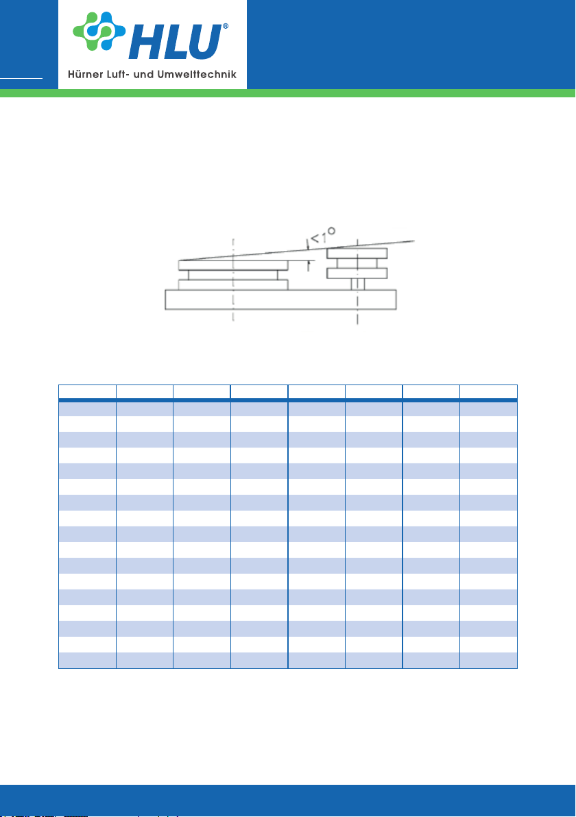
Deect a belt (the central belt with multiple-groove pulleys) at right angles to the free belt side by
means of a spring balance. Measure the deexion using a centimetre ruler. A required deexion
(Ea) of 17 mm per 1000 mm of free belt side length was determined. The required deexion is
calculated by means of the following simplied equation:
(e = Centre distance)
www.hlu.eu
06.2019
Page 32
Operating manual
Centrifugal fans
32
Before work starting, note that:
J Secure the fan against accidental start-up.
J Remove the belt cover.
J Measure the spring travel f = Ea at test force F using a traction balance
J Increase or reduce the motor-to-bearing centre distance by adjusting the mounting screws
until reaching the set-point. For this, release the locknut at the upper and lower setscrew.
Shaft and belt pulleys must be exactly aligned, maximum deviation is 1°.
The values for test force depend on the prole and diameter of the little belt pulley (see next
schedule).
Disc Test load Disc Test load Disc Test load Disc Test load
SPA95 23 SPB150 42 SPC224 85 SPZ63 12
SPA100 25 SPB160 45 SPC236 88 SPZ67 13
SPA106 27 SPB170 48 SPC250 92 SPZ71 14
SPA112 29 SPB180 51 SPC265 96 SPZ75 15
SPA118 31 SPB190 54 SPC280 100 SPZ80 16
SPA125 33 SPB200 58 SPC300 106 SPZ85 17
SPA132 35 SPB212 61 SPC315 110 SPZ90 19
SPA140 36 SPB224 64 SPC335 115 SPZ95 20
SPA150 38 SPB236 66 SPC355 120 SPZ100 21
SPA160 39 SPB250 69 SPC375 123 SPZ112 22
SPA180 42 SPB280 77 SPC400 126 SPZ125 24
SPA180 45 SPB315 85 SPC425 130 SPZ140 25
HF R | RV | MRV
SPC450 134
SPC475 138
SPC500 141
SPC530 146
SPC560 150
06.2019
www.hlu.eu
Page 33
Operating manual
Centrifugal fans
HF R | RV | MRV
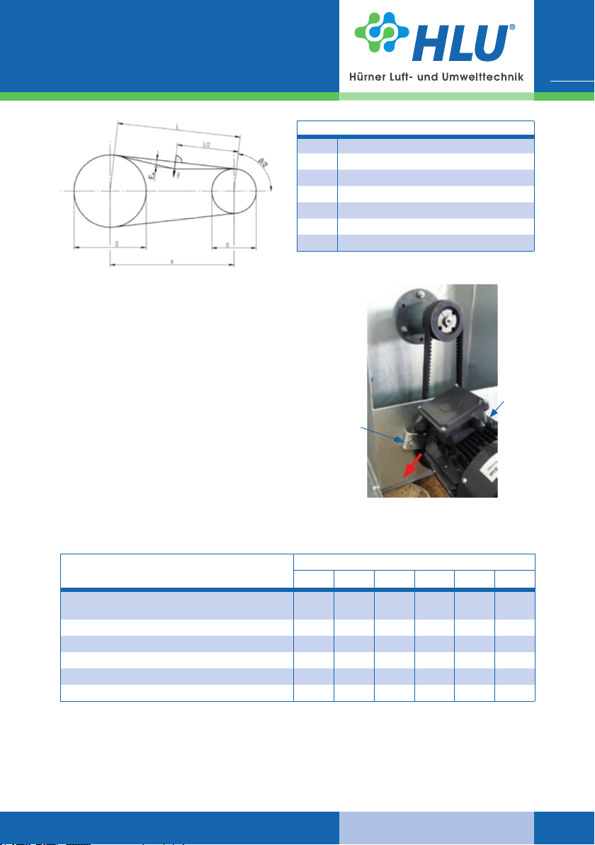
e Centre distance
ß Angle of belt contact
D Diameter of big pulley
d Diameter of little pulley
F Test force in N
L Free belt length
Ea Required deexion in mm
Retension of V-belt
Loosen both screws on the motor ange
(A bearing). Then pull the motor at the terminal box at
a 45 ° angle downwards [F] so that the belt is tensioned. Tighten the screws slightly, then pull the motor
downwards at an angle so that the belt tension rises
again. While the tension is maintained, rst tighten
the screw with the clamping angle (1), then tighten
the screw directly at the ange (2).
Then check the belt tension again and if necessary repeat the process until the required tension is
reached (if sucient force can not be applied, use
torque-increasing measures [leverage]).
33
Designation
(2)
(1)
[F]
8.4 Inspection interval / Function checking
Interval with single-shift operation
d w m ½ y 1 y MO
Superordinate facility for connecting the
supply voltage
Settings of the on-site protective devices x
Fan motor function checking x
Bearing function checking x
Check belt tension and correct if necessary x
Check the impeller for damage x
x
www.hlu.eu
06.2019
Page 34
Operating manual
Centrifugal fans
34
8.5 Vibrations
International standards for the balancing quality and vibration values for industrial fans are dened in the standard ISO 14694:2003. The vibrations are measured radially on the shaft bearing
of the drive motor. If a measurement is not possible directly on the motor, it is measured radially
at the next point that has a mechanical connection to the motor. The following table shows the
fan application categories for maximum permissible vibration.
HF R | RV | MRV
Vibration values according to ISO 14694
Stan-
dard
group
ISO
14694
BV-2 >0.15<3.7 G16 3.5 (5.1) 5.6 (7.6)
BV-3 >=3.7<37 G6.3 2.8 (3.8) 3.5 (5.1)
BV-4 >=37<300 G2.5 1.8 (2.5) 2.8 (3.8)
Motor
power
[kW]
Min.
balan-
cing
quality
At manufacturer
Average values;
maximum values
in brackets
Fixed
mounted
[mm/s]
Flexibly
mounted
[mm/s]
Limit values
In operation
Average values;
maximum values
in brackets
Fixed mounted
[mm/s]
Start-up 5.6 (7.6)
Alarm 9.0 (12.2)
Slow-down 10 (14)
Start-up 4.5 (6.4)
Alarm 7.1 (10.2)
Slow-down 9.0 (12.7)
Start-up 2.8 (4.1)
Alarm 4.5 (6.4)
Slow-down 7.1 (10.2)
Flexibly mounted
[mm/s]
Start-up 9.0 (12.7)
Alarm 14.0 (19.1)
Slow-down 16 (21)
Start-up 6.3 (8.8)
Alarm 11.8 (16.5)
Slow-down 12.5 (17.8)
Start-up 4.5 (6.4)
Alarm 7.1 (10.2)
Slow-down 11.2 (15.2)
8.6 Tightening torques for bolt connections
On the basis of VDI 2230 the following tightening torques are recommended for bolts of strength
class 8.8:
Nominal
diameter [mm]
M4 3,3
M5 6,5
M6 11,3
M8 27,3
M10 54
Tightening
torques [Nm]
Nominal
diameter [mm]
M12 93
M16 230
M20 464
M24 798
Tightening
torques [Nm]
06.2019
www.hlu.eu
Page 35
Operating manual
Centrifugal fans
HF R | RV | MRV
8.7 General hints for maintenance
Correct maintenance is decisive for the fan safety of operation and lifetime.
Operational disorders due to insucient or improper maintenance can cause high repair costs
and long downtimes.
For this reason, regular maintenance is indispensable.
Before starting maintenance and repair work (especially when the
fan must be opened), compliance with the switch-o procedures is
essential.
35
The inspection intervals must be shortened at strong degree of pollution, high
ambient temperatures and frequent start / many load changes. Interval
Check, if the fan is installed correctly and safely and pay attention to possible
vibrations during operation. If necessary, re-tighten the screw connections.
Check the connections of the pipe on the inlet and outlet side, housing cover and
shaft seal (if installed) for tightness.
Check the electric motor for correct and rm seating and functionality. MO
Check V-belts ½ y
Check the housing for stress cracks, quiet run and storage temperature. Check
the impeller for deformations, wear and cakings.
Do all greasing work at the bearings of the fan rotational. Keep attention to the
lubricating intervals of the engine manufacturer.
Checks
m
m
y
MO
8.8 Checks
After completing work, please, check:
J The completeness of performed work,
J Unless there is reason to complain, the fan can be taken into operation
After checking and replacing the wear parts, please check, if all safety
devices are fully operable.
www.hlu.eu
06.2019
Page 36
36
9. Troubles, causes and measures
The facts and information relating to „Troubles, cause and measures“
described in this operating manual are formulated in a way that they
are understood by persons with a professional training in the elds of
J electrics / electronics
J mechanics / maintenance.
Appropriate tools and test equipment must be made available to this
personnel. Before any maintenance and repair work, the fan must be
de-energized and protected against re-activation. Unless the speci-
ed measures are successful, please, contact the manufacturer.
Trouble Possible cause Remedial action
Temperature
rise at the
bearings
Leakage
at the shaft
passage
Unquiet run
of fan (heavy
vibration)
Motor
bearing noise
Fan power
output too
low
Motor power
consumption
to high
Motor is
switched o
by the motor
protection
switch
Increased exing work at bearing by
fresh lubrication or new bearing
Lubrication intervals were not observed
V-belt tension too high Correct V-belt tension
Sealing element worn out Change sealing element
Foundation is subject to heavy vibration
Impeller unbalance
Deposits on the impeller Clean the impeller
Damage on impeller Consult manufacturer
Motor bearing damaged
Wrong impeller rotating direction Reverse the rotating direction
Output reduction facilities are not opened, or opened only partly
Pipe resistances on inlet or outlet side
too high
Defective motor winding
Wrong impeller rotating direction Reverse the rotating direction
Motor protective switch is not adjusted
correctly
Motor protective switch is not adjusted
correctly
Motor winding defective
Impeller blocked Check impeller
Operating manual
Centrifugal fans
HF R | RV | MRV
Fan continue to operate, Temperature
normalizes after a certain period by
itself
Change bearing and correct the lubrication according to the intervals
Damp the foundation / fan
Balancing required, consult manufacturer
Replace bearing or motor,
Consult manufacturer or motor supplier
Check the output power reduction
facilities
Reduce resistances, increase the fan
power, consult manufacturer
Change motor, consult manufacturer or
motor supplier
Adjust motor protective switch correctly
Adjust motor protective switch correctly
Change motor,
consult manufacturer or motor supplier
06.2019
www.hlu.eu
Page 37
Operating manual
Centrifugal fans
HF R | RV | MRV
Trouble Possible cause Remedial action
Belt broken
or damaged
V-belts slip
through
Sliding
noises
Sudden power decrease
10. Emergency
In case of emergency, switch o the main switch or withdraw the power supply connector.
Normal abrasion Find reason, change V-belts
V-belt tension too high Reduce V-belt pre-tension
V-belt does not align Check alignment
Wrong pre-tension
Backlash due to decreasing V-belt
pre-tension
Motor winding defective Consult manufacturer
Impeller unbalance
Foreign body between impeller and
housing
Inlet or outlet pipe untight Check the pipes
Connecting collar defective Replace the collar
Check belt tension and correct if
necessary
Check and re-adjust the V-belt
Balancing required, consult manufacturer
Remove the foreign body
37
11. Dismantling / Disposal
Dismounting
Dismounting may be done only by qualied personnel.
Before starting dismounting work, make sure that the switch-o proce-
dures are followed.
Disposal
The fan is made mainly of steel and plastics (except the electrical
equipment) and must be discarded in compliance with the applicable
local environmental regulations.
For discarding the cleaning agents, follow the local regulations and the
information given in the manufacturer safety data sheets.
Contaminated cleaning tools (brushes, clothes, etc.) must be discarded
in compliance with the manufacturer specications as well.
Depending on the fan application, the housing and the impeller must be
considered as special waste and discarded accordingly.
Injection moulded or sintered housings are provided with recycling
signs indicating which type of plastic material was used.
www.hlu.eu
06.2019
Page 38

38
Operating manual
Centrifugal fans
HF R | RV | MRV
Notes
06.2019
www.hlu.eu
Page 39

Operating manual
Centrifugal fans
HF R | RV | MRV
39
www.hlu.eu
06.2019
Page 40

www.hlu.eu
Hürner Luft- und Umwelttechnik GmbH
Ernst-Hürner-Straße
35325 Mücke-Atzenhain
Germany
Tel + 49 6401 9180 - 0
Fax + 49 6401 9180 - 142
HLU Systemtechnik GmbH
Sälzerstraße 20a
56235 Ransbach-Baumbach
Germany
Tel + 49 2623 92 95 9 - 0
Fax + 49 2623 92 95 9 - 99
Edition 06/2019
 Loading...