

Page 1

1
TOP HEADER
Operators Manual
In a world of compromise, some don’t.
®
HK SL8-1 Rifle
Caliber .223
(5.56mm)
Page 2

SL8-1
Sporting Rifle
Operators Manual
CAUTION: Read the safety notes before handling the
SL8-1 Rifle!
© Heckler & Koch, Inc., 10/99, 11/99 (revised May 2000)
All rights reserved
HK, Inc., 21480 Pacific Blvd.
Sterling, Virginia 20166-8903
United States of America
Telephone (703) 450-1900
Specifications and models subject to change without notice.
®
Page 3

Maintenance and Service ..................................................................38
Troubleshooting Guide ........................................................................41
Parts & Exploded Diagram..................................................................42
Specifications ......................................................................................44
Firearm Service Record ......................................................................45
4
5
TABLE OF CONTENTS
TABLE OF CONTENTS
Safety Notes on the Use of the SL8-1 rifle ..........................................6
General ................................................................................................8
Assembly Groups ................................................................................10
Description of Assembly Groups ........................................................11
Group 1 Receiver with barrel, buttstock and attaching parts ........11
Group 2 Bolt Assembly ..................................................................12
Group 3 Buttstock Assembly (with trigger & safety mechanism) ..14
Group 4 Handguard ......................................................................16
Group 5 Magazine ..........................................................................16
Handling and Operation ....................................................................17
Operation of Parts ..............................................................................22
Disassembly of the SL8-1 ..................................................................24
Assembly of the SL8-1 ........................................................................28
Disassembly and Assembly of the magazine ....................................30
Adjustment of the Stock and Cheekpiece ..........................................31
Adjustment of the Sights ....................................................................33
Optical Sights ....................................................................................35
Page 4

6
7
SAFETY NOTES
SAFETY NOTES
• Always point the rifle in a safe direction.
• Before handling and before cleaning it has to be checked to
ensure that:
- The bolt is locked to the rear
- The rifle is unloaded (cartridge chamber empty)
- The barrel is free of obstructions
- The magazine is empty.
• Keep your finger off the trigger when loading, unloading or
otherwise handling the rifle. Always place the trigger finger
outside of the trigger guard.
• Place your finger on the trigger only when your sights are
aimed at the target.
• Never use force when handling, disassembling, cleaning and
assembling the rifle.
• Disassemble the rifle only as far as described in this manual.
• Always wear eye and hearing protection when using the rifle.
• Take into account the fact that bystanders are also endangered.
Ensure bystanders are also wearing ear and eye protection.
• Only use factory-loaded and undamaged cartridges of the
correct caliber.
• Always mind that the muzzle area is free of obstacles during
firing.
• Store the firearm and ammunition in separate places.
• Discharging firearms in poorly ventilated areas, cleaning
firearms, or handling ammunition may result in exposure to
lead, a substance known to be associated with birth defects,
reproductive harm, and other serious injury. Have adequate
ventilation at all times. Wash hands thoroughly after exposure.
• Heckler & Koch does not assume any liability for events due to
disregarding this manual, improper handling, negligence,
improper treatment, use of improper or reloaded ammunition,
unauthorized exchange of parts or manipulations of the rifle.
• Remember, firearms safety begins with you. Read this operators
manual and be familiar with the safe handling of this firearm
before using it. Store all firearms in a safe and secure location.
Keep firearms away from children. Always be a safe shooter.
Keep this manual with the rifle.
Safety Notes on the Use of the HK SL8-1
Clear the rifle! Before handling the firearm, “clear it!” Do so by:
1 • Make sure fingers are outside of the trigger guard and the
firearm is pointed in a safe direction at all times!
2 • ON SAFE – Rotate the safety/selector lever to the “Safe”
position (the white “S” adjacent to the safety/selector lever)
3 • REMOVE MAGAZINE – Depress the magazine paddle release
lever and remove the magazine from the magazine well.
4 • COCKING LEVER – Rotate the ejection port towards the
ground and fold out and pull the cocking lever rearward one or
more times to insure the chamber is empty. Watch for a live
round or empty case to be ejected. Move the cocking lever
upward slightly and lock it into the indent in the cocking lever
housing to lock the bolt open.
5 • BOLT CATCH – While holding the cocking lever fully rearward
use the trigger finger to press upwards on the bolt catch button
located in the front top corner of the trigger guard to lock the
bolt rearward.
6 • INSPECT CHAMBER – Inspect chamber for the presence of a
live round or empty case.
Visually – View chamber through open ejection port.
Physically – Insert index finger through magazine well or
ejection port and feel for the presence of a round or cartridge
case in the chamber.
7 • Remove any live rounds or empty cases from the chamber or
from within the firearm or magazine before handling the firearm
further.
The HK SL8-1 is now considered “Clear.
WARNINGS
• Carefully read this operators manual before handling the rifle.
• Only use the rifle after you have fully reviewed and
understand these instructions.
• Observe all notes on handling and operation. Failure to do so
may result in injury or death of the operator or bystanders.
• Do not use the rifle if you have previously ingested alcohol or
drugs.
• When passing the rifle between persons, the firearm must be
clear and the bolt should be open.
• Always treat the rifle as if it were loaded and ready to fire.
• Never point the rifle at anyone during handling.
Page 5

8
9
GENERAL
GENERAL
Figure 2 SL8-1 with mechanical sights (right side view)
Figure 3 SL8-1 Accessories
The HK SL8-1 semiautomatic rifle is a caliber .223 Remington civilian
sporting arm based on the G36 rifle currently used by the German Army.
The SL8-1 rifle is gas operated with a rotating bolt head. Its receiver,
pistol grip, buttstock, and handguard are all made of a high-strength
polymer material, resulting in a tough and lightweight rifle.
A mechanical sight is mounted on the Picatinny long rail found on the
top of the upper receiver. This sighting system can be easily replaced by
other sighting systems, including optical scopes.
A movable buttplate and cheekpiece are other features that can be
adjusted to the individual needs of the user.
The heavy barrel and the chamber are cold hammer forged and hard
chrome plated for durability and accuracy. The barrel is fastened and
centered to the receiver by means of a hex nut.
A cocking lever on the front end of the bolt head carrier can be swiveled
to the left and to the right for actuation by both left and right handed
users.
The magazine holds 10 rounds.
A bolt catch locks the bolt rearward (open) when the last round is fired
or an empty magazine is inserted and the bolt is retracted.
Figure 1 SL8-1 with mechanical sights (left side view)
Page 6

11
Group 1 Receiver with barrel, buttstock and attaching parts
The receiver is made of high-strength fiber-reinforced plastic. It houses
all the other assembly groups. Inside the receiver there are guideways
for the bolt as well as contact surfaces for the pistol grip, the buttstock
and the magazine well. The barrel is fastened and centered to the
receiver by means of a nut.
CAUTION: The barrel nut should not be removed by the operator.
Only HK certified armorers should attempt to remove the barrel.
On the right side of the receiver is an ejection port with an integral
cartridge case deflector. The cartridge case deflector directs the ejected
cases (at an angle of approximately 45° to the muzzle) away from the
shooter.
Handguard and magazine well are fitted to the bottom of the receiver by
means of removable locking pins.
The buttstock with trigger mechanism is fastened to the receiver by
means of two hex head screws. To fasten and unfasten them use the
HK special tool provided with the rifle.
Figure 5
Receiver with barrel, gas system, mounting rail with mechanical sights
1. Barrel
2. Front sight
3. Mounting rail
4. Rear sight
5. Receiver
6. Magazine catch
7. Magazine well
DESCRIPTION OF ASSEMBLY GROUPS
10
ASSEMBLY GROUPS
Figure 4 SL8-1 Assembly groups
1 Receiver with barrel, gas system, magazine well,
mounting rail with mechanical sights
2 Bolt assembly with recoil spring assembly
3 Buttstock assembly complete
4 Magazine
5 Handguard
Page 7

13
The firing pin is retained by the firing pin retaining pin.
A cocking lever on the front end of the bolt head carrier can be swiveled to
the left and to the right for actuation by both left and right handed users. It
can also be locked in a 90° position to the left and right for use as a
forward assist.
Figure 7 Bolt assembly with recoil spring assembly
The recoil spring guide rod with the recoil spring is a separate unit and
fits into the bolt head carrier. Rearward movement of the bolt assembly
is stopped by a buffer in the buttstock.
Figure 8 Bolt assembly
1. Cocking lever 4. Retaining pin
2. Bolt head carrier 5. Cam pin
3. Firing pin 6. Bolt head
Figure 9 Bolt head
DESCRIPTION OF ASSEMBLY GROUPS
12
DESCRIPTION OF ASSEMBLY GROUPS
Gas block
The gas block is fastened with a cross pin to the barrel; do no attempt to
remove it. After the bullet has passed the gas vent hole in the barrel, a
portion of the propellant gases are guided into the gas cylinder within
the gas block and actuate the gas piston.
The gas piston drives the bolt assembly rearward via the push rod. The
return spring on the push rod returns the rod to its starting position.
Figure 6 Gas system
Magazine well
The front of the magazine well engages into two support studs on the
receiver. For fastening the magazine well is swiveled upward. A locking
pin fastens both the pistol grip and the magazine well to the receiver.
When the locking pin is removed the magazine well is retained by the
magazine catch.
Group 2 Bolt assembly
The bolt assembly with the rotary bolt head is guided into the receiver
by metal guide rails molded into the polymer receiver. The bolt assembly
is driven rearward by the gas piston and forward by the recoil
spring.The bolt assembly serves multiple functions including; feeding the
cartridges, locking of the chamber, cartridge ignition, case extraction
and ejection, as well as for cocking of the hammer.
The bolt head is retained in the bolt head carrier by the cam pin which
also controls its rotary movement. Locking lugs are machined onto the
front of the bolt head. The spring-loaded extractor is located in a gap
between the locking lugs. Adjacent to the extractor is a spring-loaded
ejector.
1. Extractor
2. Ejector
3. Locking lugs (6 total)
Page 8
15
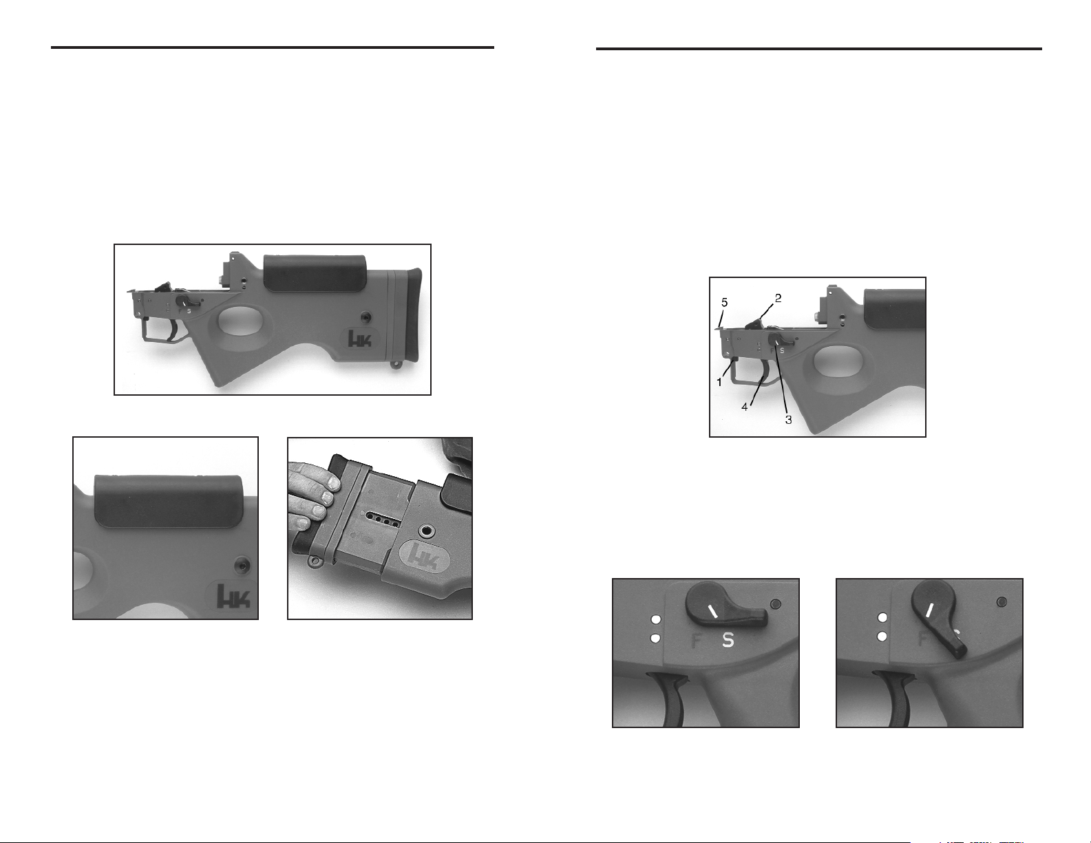
Trigger and Safety Mechanism
The trigger and safety are integrated into the buttstock assembly.
At the front of the trigger guard there is a bolt catch button which is
used to hold the bolt open on an empty magazine or when fired “dry.”
There are safety selector levers on both sides of the grip. The
safety/selector levers can be placed in two positions:
“S” = Safe (white index line on the safety/selector
lever pointing to the white “S”)
“F” = Fire (semi-automatic white index line on the
safety/selector lever pointing to the red “F”)
Figure 13 Trigger and safety mechanism
1. Bolt catch button
2. Hammer
3. Safety/selector lever
4. Trigger
5. Bolt catch
Figure 14A Safety/selector position Figure 14B Safety/selector position
“safe” “fire” (semi-automatic)
DESCRIPTION OF ASSEMBLY GROUPS
14
DESCRIPTION OF ASSEMBLY GROUPS
Buttstock Assembly, complete
The buttstock is fixed to the receiver by the means of two hex head
screws which can be opened and closed with the HK Tool. The buttstock
includes an integral rear sling attachment point.
Butt plate and cheekpiece can be adjusted to the individual requirement
of the user by the means of spacers.
The trigger and safety/selector lever is located at the front end of the
buttstock.
Figure 10 Buttstock assembly complete
Figure 11 Figure 12
Cheekpiece Buttplate with
interchangeable spacers
Page 9

17
Ammunition and Accuracy
By using ammunition with match bullets (like Sierra 62 grain Match King
#1410) or other match grade ammunition the HK SL8-1 will achieve the
best level of accuracy.
If used, handloaded ammo should not exceed the maximum gas
pressure specified by C.I.P. and SAAMI for the cal. 223 Remington
cartridge (5.56 x 45mm NATO). Follow the instructions of propellant and
bullet manufacturer.
Mounting Rail
The rail with mechanical iron sights is not designed to be a carrying
handle.
CAUTION: Except for loading and unloading the rifle there should be
no finger placed between the rail and the receiver.
NOTE: If the bolt is locked to the rear by the bolt catch and the
magazine is removed, a hard knock on the buttstock, like slamming
the gun to the ground will release the bolt. However, to avoid
damage to the rifle, the bolt should be pulled fully rearward and
released.
Safe handling
Compared to the military issue G36 assault rifle, the trigger pull of the
SL8-1 is significantly reduced. If the weapon is loaded, avoid rough
handling and drops.
Because of the absence of a firing pin spring, a slight mark on the
primer can be seen after chambering a round. This has no influence on
the handling safety of the rifle; without pulling the trigger the gun will not
fire. Please avoid chambering the same round several times in
sequence as the bullet can be worked loose from the cartridge.
NOTE: Use only .223 Remington or 5.56 x 45mm NATO ammunition
in the SL8-1 rifle. Damage caused by the use of improperly
assembled or remanufactured ammunition in the SL8-1 may void the
HK Warranty. Do not use ammunition assembled with corrosive
components (primers, propellants, etc.).
HANDLING AND OPERATION
16
DESCRIPTION OF ASSEMBLY GROUPS
Handguard
The detachable handguard encloses the barrel and the gas system. The
handguard is positioned at the receiver by means of two support studs
and is fastened there by means of a removable locking pin. The
handguard incorporates a sling attachment point and two threaded hard
points for accessory attachment.
Figure 15 Handguard
Magazine
The detachable box-type magazine holds maximum 10 rounds. The
magazine housing consists of impact-resistant transparent plastic which
allows the user to visually check the contents of the magazine from the
outside.
Figure 16 Magazine Figure 17 Magazine disassembled
The magazine consists of:
1. Magazine housing
2. Magazine floor plate
3. Follower
4. Follower spring
Page 10

19
Loading the Rifle
Method 1: No magazine in the weapon
The bolt is in its forward (locked) position
1 • Set the safety/selector lever on “Safe.”
2 • Swivel the cocking lever to the left or to the right, pull it all the
way to the rear (Figure 20) and hold it.
Figure 20 Operating the cocking lever
3 • Push the bolt catch button upward to lock the bolt open
(rearward, see Figure 21)
Figure 21 Activate bolt catch, push upwards
4 • Insert a loaded magazine into the magazine well until the
magazine catch clearly engages. Swivel the cocking lever out,
pull it all the way to the rear and release it.
The weapon is now loaded and set on “Safe.”
HANDLING AND OPERATION
18
HANDLING AND OPERATION
Cartridges assembled with projectile weights from 50-70 grains are
recommended for use with the SL8-1 rifle.
Loading of the magazine
1 • Hold the magazine with one hand. Place a cartridge with the
other hand slightly forward of the the magazine lips and push
back and downward until the cartridge is held underneath the
lips.
2 • Repeat this operation until the magazine is fully loaded and the
desired 10 rounds are inside the magazine.
Figure 18 Loading of the magazine
Unloading the magazine
Hold the magazine with one hand. Push the cartridges forward out of
the magazine with the thumb of the other hand. Do not allow the
cartridges to drop on a hard surface or they may become damaged.
Page 11

21
Forward assist
If the exterior of the rifle is very dirty (sand, mud etc.) the cocking lever
can also be used as a forward assist.
To use the cocking lever as a forward assist
1 • Swivel out the cocking lever and push it inward against the bolt
head carrier (the cocking lever remains in its swiveled position).
2 • Push the bolt head carrier with the cocking lever forward until it
fully locks closed.
3 • Pull the cocking lever outward and let it swivel to its initial
position (parallel with the bolt head carrier).
Figure 23 Cocking lever shown in
its “forward assist” position
Low-noise loading using the forward assist
1 • After the magazine has been inserted, swivel out the cocking
lever and push it inward against the bolt head carrier until it
engages (see Figure 23).
2 • Pull the cocking lever slightly to the rear and guide it forward.
3 • Push the cocking lever forward until the bolt locks.
4 • Pull the cocking lever outward and let it swivel to its initial
position (parallel with the bolt head carrier).
The rifle is now loaded and set at “Safe.”
WARNING: Never fire the SL8-1 with cocking handle locked in the
90° forward assist position or injury may occur.
HANDLING AND OPERATION
20
HANDLING AND OPERATION
Reloading the Rifle
Method 2: The magazine in the weapon is empty.
The bolt has been held in its rear position by the bolt
catch.
1 • Set the safety/fire selector lever at “Safe.”
2 • Push the magazine catch forward with the thumb and remove
the empty magazine (see Figure 22 below).
Figure 22 Release magazine (push forward)
3 • Insert a loaded magazine into the magazine well until the
magazine clearly engages. Tug on the magazine to ensure it is
securely engaged.
4 • Swivel the cocking lever out, pull it all the way to the rear and
release (see Figure 20).
The weapon is now loaded and set on “Safe.”
Page 12

22
OPERATION OF PARTS
Bolt Locked
The barrel is tightly screwed to the barrel extension by means of a nut.
The bolt head carrier houses the bolt head which can move along its
longitudinal axis inside the bolt head carrier. Additional to its longitudinal
movement the bolt head can also rotate around its longitudinal axis.
In the locked condition the bolt head is in the foremost position. The bolt
head in the bolt head carrier is turned in such a way that the locking
recesses of the bolt head engage the corresponding locking lugs of the
barrel extension.
The SL8-1 is now loaded and safety selector lever set to fire.
Pulling the trigger releases the hammer which hits the firing pin and
ignites the cartridge.
The propellant gases accelerate the bullet. As soon as the bullet has
passed the gas vent hole, a portion of the gases enter the gas block
and the gas cylinder.
These gases push the bolt head carrier via the gas piston and the push
rod to the rear. The camming slot in the bolt head carrier causes the
cam pin to pivot downward, which in turn rotates the bolt head and
unlocks it.
Figure 24 Bolt in locked position
1. Gas piston 6. Firing pin
2. Push rod 7. Camming slot
3. Bolt head 8. Barrel extension
4. Bolt head carrier 9. Barrel
5. Cam pin 10. Gas Block
23
Bolt Unlocked
The locking lugs disengage. The bolt head disengages (unlocks) from
the barrel extension. Bolt head carrier and bolt head move to the rear.
The extractor in the bolt head extracts the cartridge case by its rim from
the chamber. When the bolt assembly passes the ejection port, the
spring-loaded ejector ejects the cartridge case through the open
ejection port forward and to the right.
The rearward movement of the bolt assembly compresses the recoil
spring and cocks the hammer.
If the magazine is empty, the follower lifts the bolt catch upwards which
holds the bolt rearward. If a round is present in the magazine, the bolt
assembly, driven by the recoil spring moves forward and pushes the
uppermost cartridge out of the magazine into the chamber.
The bolt head contacts and stops at the rear face of the barrel and the
bolt head carrier continues its forward movement which rotates the bolt
head via the cam pin and the camming slot into the locked position.
The firing pin tip can only protrude through the bolt face and hit the
primer when the bolt is fully locked. The weapon is now ready to fire
again.
Figure 25 Bolt in the unlocked position
1. Gas piston 6. Firing pin
2. Push rod 7. Camming slot
3. Bolt head 8. Barrel extension
4. Bolt head carrier 9. Barrel
5. Cam pin 10. Gas block
OPERATION OF PARTS
Page 13

25
Stripping into assembly groups
1 • Use the 5 mm Allen wrench of the HK tool and remove the hex
headed Allen screws located on the left and right sides of at the
rear end of the receiver
2 • Remove the locking pin above the front end of the trigger
guard.
3 • Pull buttstock with trigger back out of the receiver.
4 • Pull the cocking lever to the rear and remove the bolt.
5 • Pull out the locking pin at the handguard and remove the
handguard to the front.
6 • Push the magazine catch, swivel the magazine well downward
and detach.
Figure 26 Stripping SL8-1 into assembly groups
DISASSEMBLY OF THE SL8-1
24
DISASSEMBLY OF THE SL8-1
Clear the rifle! Before handling the firearm, “clear it!” Do so by:
1 • Make sure fingers are outside of the trigger guard and the
firearm is pointed in a safe direction at all times!
2 • ON SAFE – Rotate the safety/selector lever to the “Safe”
position (the white “S” adjacent to the safety/selector lever)
3 • REMOVE MAGAZINE – Depress the magazine paddle release
lever and remove the magazine from the magazine well.
4 • COCKING LEVER – Rotate the ejection port towards the
ground and fold out and pull the cocking lever rearward one or
more times to ensure the chamber is empty. Watch for a live
round or empty case to be ejected.
5 • BOLT CATCH – While holding the cocking lever fully rearward
use the trigger finger to press upwards on the bolt catch button
located in the front top corner of the trigger guard to lock the
bolt rearward.
6 • INSPECT CHAMBER – Inspect chamber for the presence of a
live round or empty case.
Visually – View chamber through open ejection port.
Physically – Insert index finger through magazine well or
ejection port and feel for the presence of a round or cartridge
case in the chamber.
7 • Remove any live rounds or empty cases from the chamber or
from within the firearm or magazine before handling the firearm
further.
The HK SL8-1 is now considered “Clear.” Once clear, let the bolt move
forwards.
NOTE: The SL8-1 is easily disassembled and reassembled with the
HK Tool. Do not use force in any of the disassembly procedures.
Disassembly beyond the procedures outlined in this manual is not
recommended and may void the HK Warranty. Disassembly beyond
the operators level described here may be carried out by qualified
maintenance personnel only. Contact HK for more information.
Page 14

27
Disassembly of the bolt assembly
1 • Push the firing pin retaining pin to the left (e.g. with
gas piston) and detach.
2 • Remove the firing pin to the rear.
3 • Take out the cam pin to the left.
4 • Detach the bolt head to the front.
Figure 29 Bolt head disassembled
DISASSEMBLY OF THE SL8-1
26
DISASSEMBLY OF THE SL8-1
Disassembly of the push rod and the gas piston
CAUTION: The push rod is under considerable spring tension. Use
caution when installing and removing it. To avoid injury to yourself
and others, never point the compressed push rod in an unsafe
direction in the event it is inadvertently released under pressure.
1 • Push the push rod to the rear against spring pressure and
remove it from the gas piston.
2 • Swivel the push rod to the side and remove it to the front.
3 • Remove the gas piston to the rear.
Figure 27 Removing push rod
Figure 28 Removing the gas piston
Page 15

29
Figure 31 Installing the push rod
Assembly of the SL8-1
1 • Slide the handguard from the front over the barrel and the
receiver. Align notches onto studs.
2 • Fasten the handguard with the locking pin.
3 • Place the front of the magazine well onto the bearing studs,
swivel the rear of the magazine well upward all the way until it
engages the magazine catch.
4 • Insert the bolt assembly from the rear into the receiver together
with the recoil spring.
5 • Push buttstock assembly with trigger mechanism (hammer is
back, in the cocked position) from the rear into the receiver and
insert the locking pin above the trigger guard.
6 • Fasten the buttstock to the receiver by the means of the allen
screws with the HK Tool (do not use excess force to tighten
them down).
7 • Set the SL8-1 safety/selector on “Safe!”
8 • Insert the magazine.
ASSEMBLY OF THE SL8-1
28
ASSEMBLY OF THE SL8-1
Assembly of the bolt
1 • Slide the bolt head with the extractor on the right, as viewed
from the rear, into the bolt head carrier.
2 • Insert the cam pin from the left into the bolt head carrier and
the bolt head; mind that the flat surfaces on the cam pin and
the hole for the firing pin are parallel to the bore.
3 • Introduce the firing pin from the rear into the bolt head carrier
and the bolt head.
4 • Insert the firing pin retaining pin from the left side into the bolt
head carrier to secure the firing pin and cam pin in place.
5 • Determine that all parts are assembled in proper sequence and
complete and that the bolt head and cam pin moves freely
within the bolt head carrier.
Assembly of the gas system
1 • Insert the gas piston into the gas block.
2 • Introduce the push rod into the front part of the receiver, push it
against the spring pressure into the receiver and let it slide into
the gas piston.
CAUTION: The push rod is under considerable spring tension. Use
caution when installing and removing it. To avoid injury to yourself
and others, never point the compressed push rod in an unsafe
direction in the event it is inadvertently released under pressure.
Figure 30 Installing the gas piston
Page 16

31
Buttstock adjustments
Cheekpiece and buttplate can be adjusted by means of removable
spacers to the user’s preference.
Adjustment of buttstock length
1 • Use the 5mm allen wrench of the HK Tool to remove the hex
head screw on the left and right side of the rear of the buttstock
assembly.
2 • Pull buttplate with spacer back out of the buttstock.
Figure 35 Remove buttplate with spacer
3 • To adjust the buttstock length to your requirement you can use
up to five spacers. Each spacer is 10 mm (approximately 1/2
inch wide). Maximum adjustment is 2 inches.
4 • Push back buttplate with the required number of spacers into
the buttstock and fasten the two hex head screws with the HK
Allen wrench.
NOTE: The buttstock can be set at any length without the use of
optional spacers by using the two hex head screws to secure the
buttplate in position.
ADJUSTMENT OF THE STOCK & CHEEKPIECE
30
DISASSEMBLY & ASSEMBLY OF THE MAGAZINE
Disassembly of the magazine
1 • Press the bottom of the right sidewall of the magazine inward
until the front catch is disengaged.
2 • Push the magazine floor plate to the rear.
3 • Press the bottom of the right sidewall inward until the rear catch
is disengaged.
4 • Remove the floor plate to the rear.
WARNING: The magazine spring is under pressure! Remove the
magazine spring and the follower from the bottom of the magazine
while holding the magazine with the bottom pointed downward.
Figure 32 Figure 33
Press magazine sidewalls Remove floor plate
Figure 34 Magazine disassembled
Assembly of the magazine
1 • Insert the follower and the magazine spring from the bottom
into the magazine housing.
2 • Slide the magazine floor plate from the rear onto the magazine
housing.
3 • Push the magazine floor plate all the way over the two catches
onto the magazine housing.
Page 17

33
Sight Adjustments
If the point of impact of several shots does not coincide with where you
aimed, a sight adjustment is necessary. The SL8-1 is zeroed at 100
meters point of aim point of impact using the 100 meter rear sight
aperture. For zeroing, select the 100 meter rear sight aperture.
Elevation Adjustment
• If shots are high, elevation adjustment screw is turned clockwise with
the 2.5 mm Allen wrench of the HK Tool.
• If shots are low, turn the screw counterclockwise.
• A full turn of the adjustment screw will move the point of impact 11
cm or 4-1/2 inches up or down at a distance of 100 meters.
Figure 37 Elevation Adjustment
Windage Adjustment
• If shots are right of the point of aim, use the 2 mm Allen wrench and
turn the windage adjustment screw clockwise.
• If shots are to the left of the point of aim, turn the windage adjustment
screw counterclockwise.
• One click of the side adjustment screw moves the point of impact 3.3
centimeters (or 1-1/4 inches) left or right.
Figure 38 Windage Adjustment
ADJUSTMENT OF THE SIGHTS
32
ADJUSTMENT OF THE STOCK & CHEEKPIECE
Adjustment of the cheekpiece
1 • Use the Phillips screwdriver of the HK Tool to remove the two
Phillips screws from the cheekpiece.
2 • You can use the cheekpiece alone or with up to two spacers.
3 • Tighten the cheekpiece with or without spacers to the buttstock
by using the Phillips screwdriver.
Figure 36 Adjustment of cheekpiece
Page 18

35
Optical sight with 3x magnification
Instead of the standard iron sights, an optional optical sight with 3x
magnification can be used on the SL8-1.
The sight comes with 2 Phillips screws, 2 spacers and 2 threaded
washers, to be mounted to the rail after removing front and rear sight.
Figure 40 Optical Sight
Optical Sight Reticle
The reticle of the optical sight is provided with range marks from 200 to
800 meters in increments of 200 meters.
The outer lateral surfaces of the circular reticle simultaneously serve as
lead marks when aimed at laterally moving targets, moving at
approximately 15 km/h (9m/h) speed at a range of 200 meters.
The interior diameter of the circular reticle corresponds to a target with
a height of 1.75 meters (or 5.5 feet) at a 400 meter range.
The range marks at the bottom left which help to find and set the range
at 200, 400 and 800 meters are also based on a target sized about 1.75
meters (5.5 feet).
In the same manner, the heights of the crossmarks at 600 m and 800 m
correspond to a target of approximately 1.75 m (5.5 feet) height at the
respective range.
OPTICAL SIGHTS
34
ADJUSTMENT OF THE SIGHTS
Figure 39 Proper sight alignment
NOTE: When engaging targets that are 300 meters away, flip the 300
meter rear sight aperture into position to account for the drop in the
trajectory of the projectile.
Page 19

37
Figure 42Optical sight elevation adjustment on the SL8-1
Windage Adjustment
• If the weapon’s point of impact is too far to the right, turn the windage
adjusting screw counter clockwise in the direction of the “L.”
• If the weapon’s point of impact is too far to the left, turn the windage
adjusting screw clockwise in the direction of the “H.”
NOTE: One graduation changes the point of impact by approx.
2.3 centimeters (1.0 inch) at a range of 100 meters
Figure 43 Optical sight windage adjustment on the SL8-1
OPTICAL SIGHTS
36
OPTICAL SIGHTS
Figure 41 Optical reticle
1 Point of aim at 100 and 200 meters.
2 Lead mark for firing at targets moving from left to right at a
speed of approx. 15 km/h (9 mph) at a range of 200 meters.
3 Horizontal line to determine whether rifle is canted.
4 Circular reticle (interior diameter = 1.75 meters/5.5 feet size
target at 400 meter target range) and aiming point approx. 400
meter range.
5 Point of aim for firing at 600 meter range.
6 Point of aim for firing at 800 meter range.
7 1.75 meters/5.5 feet size target at ranges X.
Adjustment of the optical sight
If a sight adjustment becomes necessary, this may be done by vertically
or horizontally adjusting the optical sight with the 2.5 mm Allen wrench
from the HK Tool.
Elevation Adjustment
• If the weapon’s point of impact is too high, turn the top adjusting
screw counter-clockwise in the direction of the “T.”
• If the weapon’s point of impact is too low, turn the top adjusting screw
clockwise in the direction of the “H.”
NOTE: One graduation changes the point of impact by approx.
2.3 centimeters (1.0 inch) at a range of 100 meters
Page 20

39
HK SL8-1 Combination Tool:
All the necessary tools to adjust and field strip the SL8-1 are part of the
HK combination tool.
Figure 44 HK Combination Tool
1. Allen wrench 2 mm (iron sight, windage adjustment)
2. Allen wrench 2.5 mm (iron sight, elevation adjustment,
Optical sight, adjustment)
3. Allen wrench, 3 mm
4. Allen wrench, 4 mm
5. Allen wrench, 5 mm (Allen head screws buttstock/receiver
and buttplate adjustment)
6. Phillips screwdriver (cheekpiece adjustment)
7. Allen wrench, 6 mm
8. Screw driver, 5 mm
NOTE: Failure to use these metric tools may cause damage to the
SL8-1 screws.
MAINTENANCE AND SERVICE
38
MAINTENANCE AND SERVICE
Cleaning and Preservation
To clean and maintain the SL8-1 self-loading rifle you may use:
• The HK cleaning kit caliber .223/5.56 mm
• Off the shelf cleaning kits caliber .223/5.56 mm
• Cotton patches and soft tissue
• Chloride and acid-free cleaning and preservation fluids
NOTE: Do not use steel tools or brushes to clean your SL8-1 or
synthetic materials like nylon when the weapon is hot. Keep
cleaning solvents away from the painted surfaces of the SL8-1, to
include the safety/selector and the “safe” and “fire” symbols. Proper
cleaning and maintenance of your SL8-1 will extend the life of the
rifle.
Normal Cleaning
You should do this after every firing of the gun:
1 • Remove magazine
2 • Set the SL8-1 safety/selector lever to “safe” and ensure the
chamber is clear
3 • Use nylon brush and soft tissue to clean the outside
4 • Lock bolt to the rear and run a bronze bristle bore brush
soaked with solvent several times through the barrel; follow with
clean patches
5 • Apply a light coat of oil to the barrel
6 • Following cleaning, check function of all parts
7 • Set the SL8-1 safety/selector lever on “safe”
Major Cleaning (To be conducted after firing 1,000 rounds or if
exposed to or submerged in water):
1 • Clean chamber and barrel extension with chamber brush
caliber .223/5.56 mm
2 • Take bolt group apart and clean its parts
3 • Disassemble the gas system and clean the gas piston
4 • Field strip magazine and clean it
5 • Apply light coat of oil to all moving parts including the metal
rails in the receiver
6 • Reassemble the SL8-1 and check function
7 • Set the SL8-1 safety/selector lever on “safe”
Page 21

41
TROUBLESHOOTING GUIDE
40
TROUBLESHOOTING GUIDE
Stoppages and Malfunctions
In the event of stoppages on the SL8-1, the weapon is to be considered
loaded until the actual cause of the stoppage has been determined.
During the elimination of stoppages, safety precautions are to be taken
into account.
If in the event of stoppages on the SL8-1, the cartridge fired from the
SL8-1 is not ignited; the bolt assembly does not close completely; or the
spent cartridge case is not ejected; then the following steps must be
taken immediately
1 • Put the SL8-1safety/selector lever on “Safe”
2 • Remove the magazine
3 • Unload the SL8-1
4 • Ensure that barrel, cartridge chamber and receiver are free
of obstacles
5 • Determine and eliminate the cause of the stoppage
Stoppage, Fault Cause Remedy
Cartridge is not ignited Ammunition fault (dud) Recock SL8-1
(dud round)
Tip of firing pin damaged Contact HK for repair
or broken
Hammer spring damaged Contact HK for repair
or broken
Bolt fails to open Cartridge case stuck in Unload: retract bolt to
after being fired chamber due to deform- eject cartridge case,
ation or dirty chamber clean if fouled. If
required, contact HK
for repair
Gas system fouled or Clean gas piston.
defective If required, contact HK
for repair
Bolt does not close Cartridge chamber dirty Clean chamber
completely, cartridge
not properly seated Barrel extension dirty Clean barrel extension
Cartridge damaged Replace cartridge
Recoil spring worn Contact HK for repair
Incomplete cocking Release cocking lever.
movement Let it snap forward
without riding it forward.
Stoppage, Fault Cause Remedy
Cartridge case not Chamber dirty Clean chamber
extracted or ejected
Extractor or or extractor Contact HK for repair
spring broken
Ejector or ejector Contact HK for repair
spring damaged
Insufficient bolt recoil Unload: Use cocking
lever to retract bolt.
Remove cartridge case.
Check for smooth
operation and check
chamber for fouling.
If required, clean
chamber.
No cartridge fed by bolt Magazine not properly Insert magazine properly
inserted or engaged.
Magazine loose Check magazine catch
and lugs on magazine
housing. If required,
contact HK for repair.
Follower spring worn Replace or repair
magazine
Magazine lips damaged Magazine housing
damaged. If required
contact HK for repair.
Magazine well damaged Return magazine well to
HK for repair
Bolt does not stay open Magazine follower Replace magazine
after last shot spring worn follower, or spring
SL8-1 trigger cannot be Sear broken or Contact HK for repair
pulled with hammer compression spring
cocked worn
Magazine stuck in Magazine damaged Replace magazine
magazine well
Magazine catch Contact HK for repair
defective
Page 22

43
PARTS LIST & EXPLODED DIAGRAM
42
PARTS LIST & EXPLODED DIAGRAM
Item Description Part Number
Rifle, SL8-1 complete 219-477
1 Housing 219-479
Barrel, complete (2-5) 217 906
2 Barrel 217 907
3 Barrel retaining nut 205 378
4 Gas block 217 919
5 Roll pin, gas block 927 605
6 Piston, complete 205 381
7 Piston rod, complete 205 384
8 Mounting Rail 217 947
9 Flat Headed Screw (3x) 986-785
10 Washer (3x) 214 112
11 Threaded Washer 214 113
Front sight, complete (12-14) 217 933
12 Front sight 217 796
13 Front sight base 217 795
14 Roll pin, front sight 928 747
15 Flat headed screw (4x) 988 428
Rear sight complete (16-24) 217 925
16 Roll pin, rear sight 987 695
17 Rear sight guard 217 992
18 Spring, elevation adjustment 217 504
19 Rear sight housing 217 991
20 Rear sight aperture 217 997
21 Spring, windage adjustment 217 518
22 Flat Spring 217 515
23 Screw, elevation adjustment 217 505
24 Screw, windage adjustment 217 517
Bolt complete (25-42) 219 560
Bolt head, complete (25-32) 219 561
Item Description Part Number
25 Bolt head 219 562
26 Extractor axle 214 644
27 Extractor 205 406
28 Extractor spring 205 407
29 Rubber pin for extractor 214 662
30 Roll pin 928 389
31 Ejector 205 408
32 Spring, ejector 205-411
Bolt head carrier complete (33-38) 217-909
33 Spring, cocking handle 205 393
34 Fork 205 394
35 Bushing 205 473
36 Cocking handle 205 395
37 Rivet 205 210
38 Bolt carrier 217 910
39 Cam Pin 205 390
Firing pin retainer, complete (40-41) 205 412
40 Firing pin retainer 205 413
41 O-ring, firing pin retainer 983 411
42 Firing pin 205 391
43 Recoil spring complete 205 445
Buttstock assembly complete (44-76,79) 219 535
44 Screw for check rest (2x) 988 372
45 Cheekpiece 217 948
46 Cheekpiece spacer 217 916
47 Buttstock 219 538
48 Spacer, Buttplate 219 537
49 Buttplate complete 219 539
50 Allen Screw, Buttstock (4) 217 903
51 Back plate 219 536
Figure 45
SL8-1 Rifle
Caliber .223
Item Description Part Number
52 Buffer 205 452
53 Hammer spring, right 205 428
54 Hammer 217 936
55 Hammer spring, left 205 429
56 Notched disk 217 614
57 Index plate 205 419
58 Compression spring 205 418
59 Sear complete 205 439
59a Slide 219 411
60 Sear spring 217 917
61 Trigger spring 217 918
62 Trigger 217 934
63 Bolt catch spring 205 466
64 Bolt catch 214 879
Locking lever, complete 219 094
65 Locking lever spring 214 616
66 Locking lever 219 095
67 Bolt 214 615
68 Locking lever 214 613
69 Elbow spring, right 217 946
Item Description Part Number
70 Elbow spring, left 205 201
72 Safety lever, right 205 437
73 Safety lever, left 217 945
74 Recessed axle 205 202
75 Clamping pin 988 371
76 Axle (3x) 205 469
77 Actuator axle 205 424
78 Magazine release spring 205 369
79 Magazine release 205 368
80 Axle 205 469
81 Magazine well 219 478
82 Locking pin, complete (2x) 214 125
83 Hand guard complete 219 551
Magazine complete (10 rounds) 219 472
83 Magazine Housing 219 473
84 Follower 219 474
85 Follower spring 219 475
86 Magazine floor plate 219 476
HK Combination Tool 988 49
Page 23

45
FIREARM SERVICE RECORD
44
SL8-1 SPECIFICATIONS
SL8-1 Rifle Serial Number ___________________________________
Number of Cumulative Total Maintenance &
Date Rounds Fired of Rounds Fired Users Name Remarks
______________________________________________________________________________
______________________________________________________________________________
______________________________________________________________________________
______________________________________________________________________________
______________________________________________________________________________
______________________________________________________________________________
______________________________________________________________________________
______________________________________________________________________________
______________________________________________________________________________
______________________________________________________________________________
______________________________________________________________________________
______________________________________________________________________________
______________________________________________________________________________
______________________________________________________________________________
______________________________________________________________________________
______________________________________________________________________________
______________________________________________________________________________
______________________________________________________________________________
______________________________________________________________________________
______________________________________________________________________________
______________________________________________________________________________
______________________________________________________________________________
______________________________________________________________________________
Caliber .223 Remington
Operating Principle Gas operated, short stroke piston, rotary
locking bolt
Mode of Fire Semi-automatic
Feed Device Single-stack polymer magazine,
10-round capacity
Sights Adjustable iron sights. and detachable MIL-
STD-1913 rail available for the attachment of
accessory targeting devices
Rifling 6X lands & grooves, right hand twist,
I turn in 7 inches
Length (overall) 38.58 inches (980 mm)
Barrel Length 20.80 inches (528 mm)
Sight Radius 17.65 inches (448 mm)
Width (overall) 2.36 inches (60 mm)
Height (overall) 9.84 inches (250 mm) with 10-rd magazine
Weights
• Overall 8.60 pounds (3.9 kilograms with magazine)
• Magazine 2.47 oz. (70 grams) 10-round, empty
Page 24

46
Page 25

In a world of compromise, some don’t.
Heckler & Koch, Inc.
21480 Pacific Blvd.
Sterling, Virginia 20166-8903
United States of America
Tel. (703) 450-1900
Fax (703) 450-8160
www.hecklerkoch-usa.com
Heckler & Koch GmbH
D-78722 Oberndorf/Neckar
Postfach 1329
Germany
Tel. 011-49-7423/79-0
Fax 011-49-7423/2280
www.heckler-koch.de
HK USA #701475 5/00
®
Remember, firearms safety begins with you. Read and follow all safety information in the
operators manual. Store all firearms in a safe and secure location. Keep firearms away from
children. Always be a safe shooter.
 Loading...