

Page 1

Service Documents
Confidential, for authorized service technicians only!
Do not disclose this information to or share these documents
with third parties.
Vertraulich! Nur für autorisierte Servicetechniker!
Nicht zur Weitergabe an Dritte freigegeben!
TECHNICAL SERVICE:
Stamer Musikanlagen GmbH • Magdeburger Str. 8 • 66606 St.Wendel • Germany
Music & Sales P.E. GmbH • Leipziger Str. 3 • 66606 St.Wendel • Germany
Note!
The components used in this product - particularly parts
affecting safety as well as speakers and transformers were developed and manufactured to certain specifications.
Please use original spare parts only to ensure the product
remains fully functional and safe.
Achtung!
Die in diesem Produkt verwendeten Komponenten, insbesondere sicherheitsrelevante Teile, Lautsprecher und Transformatoren wurden nach spezifischen Vorgaben entwickelt und gefertigt. Bitte benutzen Sie ausschließlich Original-Ersatzteile –
nur so ist die volle Funktionalität und Sicherheit gewährleistet.
SwitchBlade
Series
50 Combo
2006/08/29
Page 2

Directory
features page: 3-11
drawing-numbers-example page: 12
standard for single wire confection page: 13
HU1605-SwitchBlade 50 page: 14
exploded drawings: complete Rev.: A page: 15-16
wooden cabinet Rev.: A page: 17-18
chassis/ cabling Rev.: A page: 19-22
preamp assembly Rev.: A page: 23
poweramp assembly Rev.: A page: 24
preamp Rev.: 2B page: 25-27
poweramp Rev.: D page: 28-29
FX-board Rev.: C page: 30
footswitch Rev.: A page: 31
spare parts list Rev.: A page: 32-35
circuit diagrams preamp Rev.: A page: 36-38
poweramp Rev.: B page: 39-40
FX-board Rev.: A page: 41
footswitch Rev.: A page: 42
layout diagrams preamp Rev.: 2B page: 43
poweramp Rev.: D page: 44
FX-board Rev.: C page: 45
footswitch Rev.: B page: 46
Page 3
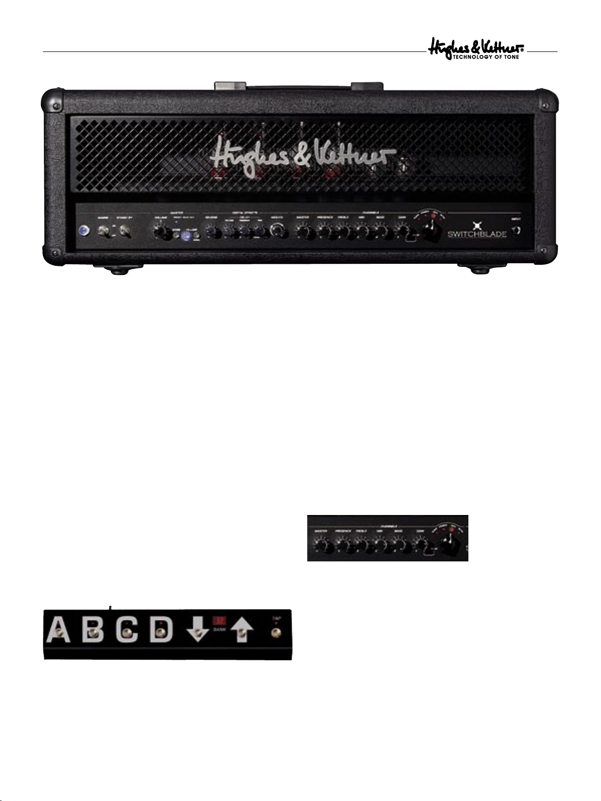
Switchblade
1 The Fundamentals of Handling
SWITCHBLADE is a tube amp and, as such, works like as a tube amp.
Nevertheless, the handling concept is rather advanced, so time spent
familiarizing yourself with it is time well spent.
At first glance, the knobs look and feel like standard-issue gear:
Control range 300 degrees; 0-10 clockwise; left and right stops.
At second glance, though, you’ll discover that there is just a single set
of knobs to serve all four Channels. One
one three-band EQ – that’s it. The selected Channel determines if the
GAIN knob addresses the CLEAN, CRUNCH or LEAD Channel.
The great advantage of this concept is that Channels are independent
and do not share the Gain, Master or voicing knobs; even Presence
is separately adjustable for every Channel and every setting can be
programmed individually to each of the 128 Presets!
Apart from the
STANDBY), this applies to all of SWITCHBLADE’s control features, that is:
VOLUME MASTER knob (and of course MAINS and
• the Channels: CLEAN, CRUNCH, LEAD, ULTRA
• the Channel settings: GAIN+BOOST, BASS, MID, TREBLE,
PRESENCE, MASTER
• the effect parameters: MOD FX, TIME, FEEDBACK, VOLUME, REVERB
• the effect routing options for external devices: FX ON/OFF, SERIAL/PARALLEL
GAIN, one Channel MASTER,
reflect the setting programmed in the Preset. This means you may
well hear something other than what you’re seeing would suggest. As
soon as you touch the knob, it will respond like any other conventional
knob. The ORIGINAL VALUE LED in the
the Preset setting. It lights up as soon as the position of the knob
corresponds to the Preset setting. More on this in chapter 4.3.
Note: You may hear a soft background sound when you twist the
knobs. This is a switching noise made the programmable resistor
matrix located behind each knob.
MASTER section tells you
2 The SWITCHBLADE’s Channels
SWITCHBLADE offers four Channels with markedly different sonic
characters. Courtesy of
more and more powerful sound-shaping options: The knobs are not
hardwired to the internal circuits, so we were able to tweak their
control ranges and performance to make the most of each Channel’s
characteristic sound.
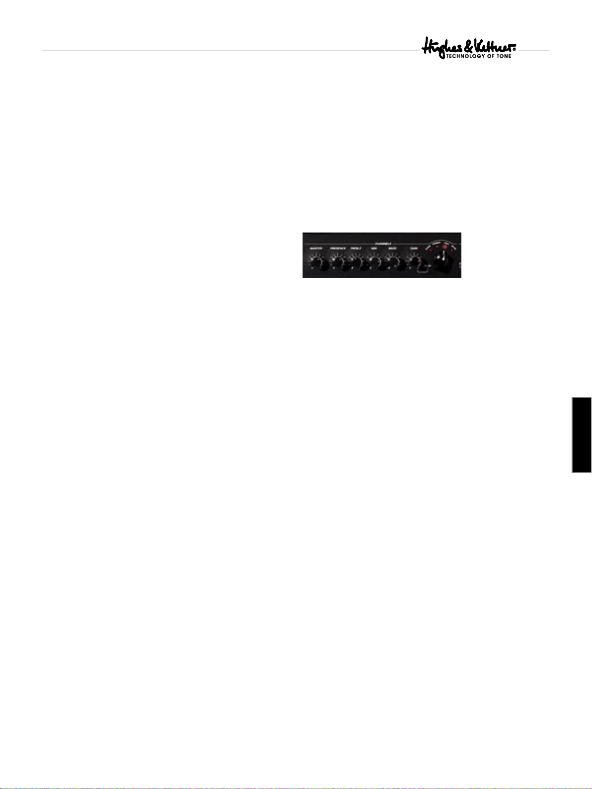
A chickenhead knob is sited at the far right of the
that’s the Channel Selector. Use it to switch among the four Channels
along with their
settings.
SWITCHBLADE’s programmability, you enjoy
CHANNEL section–
GAIN, BASS, MID, TREBLE, PRESENCE and MASTER
You won’t find any control features for managing the 128 Presets
on Switchblade. The included FSM 432 MIDI board or another MIDIenabled controller serves to select Presets and assign memory slots.
More on this in chapter 6.
Note: A knob setting programmed in a Preset and the knob’s actual
setting are not necessarily the same. They are independent: When you
switch from one Preset to another, the knob’s actual position may not
16
Note: When you first power up your amp and change Channels, you will
dial up factory settings (see chapter 6.3.2 to learn more). As soon as you
begin dialing in sounds to your taste, it will adopt your Channels settings.
And it recalls your most recently configured sound for each Channel. You’ll
find this to be a tremendous help when programming. More on this in
chapter 6.
2.1 Clean Channel
Tuned to rival classic Californian tone, Switchblade’s Clean Channel
delivers a spectrum of sweet sounds ranging from crystal-clear to
remarkably responsive Crunch tones. The programmable Presence control
adds silken warmth as well as sparkling shimmer to the sonic equation.
Page 4
Switchblade
2.2 CRUNCH Channel
Classic British overdrive à la carte! The
CRUNCH Channel covers the
diverse tonal spectrum from Clean to mean, and all points in between.
The Gain control’s integrated Boost function transforms tight rhythm
tone into a throaty growl perfect for rockin’ riffs.
2.3 LEAD Channel
The LEAD sound is the first choice for hard-rockin’, classic British
high-GAIN tone to fuel Leads, power chords and riffs. Courtesy of its
fine-tuned compression, this Channel delivers the lubricant that makes
those slick riffs and licks fly off your fingertips.
2.4 ULTRA Channel
American high-Gain sound with sumo-sized low end and snarling top
end. The
ULTRA Channel delivers the kind of merciless performance
that is sure to delight nu metal meisters and dropped tuning
aficionados. Ultra is also an alluring alternative for guitarists seeking to
super-size their sound with a high-calorie topping of rich tone.
2.5 GAIN
The GAIN knob determines Input sensitivity and thus the Level of
saturation and distortion.
feature: Just before the knob arrives at the far right position, a
SWITCHBLADE’s GAIN offers a special
BOOST
stage kicks in (and the red LED lights up). Now, when you see Boost
on other amps, this usually means all frequencies are boosted. But
Switchblade’s Boost amplifies selected frequency ranges for each
Channel to attain creamier tone.
2.6 BASS, MID, TREBLE
The voicing section is tweaked to accomplish the best, most efficient
sound-shaping for each Channel. Getting right to the heart of the sonic
matter, every knob addresses each Channel’s characteristic frequency
ranges. Like on every tube amp, the knobs of a Channel influence each
other. That is, if you boost the Treble, the midrange is cut and vice
versa. This puts a much greater range of subtle tonal variations at your
fingertips.
2.7 PRESENCE
This knob determines the overtone content. Unlike a
which boosts whatever high frequencies are available,
TREBLE knob,
PRESENCE
actually determines the amount of harmonic overtones generated by
the amp. Usually a
PRESENCE knob controls the overtone content
of the overall amp rather than of individual Channels. Courtesy of
SWITCHBLADE’s programmability, you can define PRESENCE settings
not only for each Channel, but also for each Preset.
2.8 MASTER
Use the Channel
MASTER knob to adjust the given Channel’s Volume
and balance it out with the other Channels’ Levels. On Switchblade this
knob serves another vital purpose: It lets you store the same sound
at different Volumes to any of the 128 Presets, for example, a softer
version for rhythm and a louder setting for Leads.
Note: The Channel MASTER is a different breed of knob. It adjusts the
Channels’ relative levels, and is tweaked to help you quickly dial in the
best balance. Unlike a conventional Master knob, it can’t be turned
all they way Down; it merely boosts or cuts the given Level. This
design makes musical and practical sense: The Clean Channel normally
requires a much higher Master Level than a distorted Channel, which
is why it is about as loud as the other Channels when the knob is set
to the center position. That’s why the 12 o’clock position is always the
best starting point for adjusting Volume.
3 Digital Effects
SWITCHBLADE offers three independent digital effect sections that can
be used simultaneously. Like Channel settings, all ef fect settings are
programmable.
Note: The internal effects are added to the signal via an intelligent
analog circuit. Effect routings in no way comprise the integrity of
SWITCHBLADE’s tube tone, which remains intact in all its quality.
3.1 REVERB
SWITCHBLADE’s Reverb is modeled to match the warmth and musicality
of classic spring Reverbs. A genuine improvement over its analog
forebears, it automatically adjusts the Reverb tail to suit the setting: The
REVERB you add to the signal, the longer the REVERB time.
more
3.2 DELAY
The Delay section’s
total control over all parameters. This lets you dial in everything from
rockabilly style slap-back echo to U2-inspired Delay extravaganzas and
Queen-like bombast.
3.2.1 VOLUME
Adjusts the Volume of the repetitions, sweeping from all the way off to
just as loud as the original signal.
3.2.2 FEEDBACK
Adjusts the number of repetitions from one to infinite.
3.2.3 TIME
Adjusts the Time to the next repetition from 80 ms to 1.4 s.
TIP: TIME can be remote-controlled via the included FSM 432 using
the TAP function. This lets you respond quickly and conveniently to
timing changes. You’ll find TAP to be a very helpful feature, particularly
on stage! More on this in chapter 6.1.3
3.3 MOD FX
The three most important modulation effects are
and TREMOLO, and they’re all on board, readily activated via a single
knob. CHORUS is active in the first third, FLANGER in the second third,
and TREMOLO in the final third of the control range. You can shape the
effect within its assigned third of the control range using this knob. The
parameters were tweaked to make musical sense: A twist of the knob
is all it takes to get the desired effect. Twisting clockwise adjusts the
rate of the modulation effects. Modulation depth is adjusted
VOLUME, TIME and FEEDBACK knobs afford you
CHORUS, FLANGER
english
17
Page 5
Switchblade
automatically according to the rate so that every knob position gives
you the best effect sound. To switch modulation effects off, simply
twist the knob to the far left-hand position.
3.3.1 CHORUS
At slow settings, the
CHORUS sounds thick and lush, providing a great
sound for buoyant ballads. And because effect depth is adjusted automatically, fast
CHORUS settings don’t evoke that dreaded seasick tone.
3.3.2 FLANGER
Slow FLANGER settings yield a stately sweeping whoosh effect, while
faster settings give you swirly effects often heard in contemporary rock
and pop tunes.
3.3.3 TREMOLO
The classic
TREMOLO effect is great for dialing in typical sounds of the
‘60s as well as contemporary effect sounds.
4 Master
The Master section lets you adjust the amp’s overall Volume, route
external ef fects, and store Presets.
4.1 VOLUME
4.4.1 SERIAL
Switches the effects loop from Parallel (LED does not light up) to Serial
(LED lights up).
4.4.2 FX ON
Switches the effects loop on (LED lights up) and off (LED does not light up).
Tip: If you have not inserted an effect device into the FX Loop, you
can use this circuit for other purposes and store the configurations
individually in each preset:
•
In parallel mode, you can use the RETURN jack to connect a second
instrument or any other audio source. You can also route the amp’s
signal to a second power amp.
•
In serial mode, the effects loop lets you control the amp’s volume
remotely by simply connecting an analog Volume pedal to
RETURN.
Caution: The signal chain is severed if the effects loop is configured
serially and no effect device is connected. Send is not the best to-mixer
routing option because it accesses the preamp signal only. Patch the
power amp signal to a mixing console via the Hughes & Kettner
Red Box® and the speaker outputs.
SEND/
5 Rear Panel Connections and Control Features
As the name would indicate, this knob puts the power amp at your
thumb and forefinger’s command. Exercise restraint when handling
this knob to make music a pleasant rather than a painful experience.
Handling: Unlike the Channel and effect knobs, the MASTER VOLUME
knob is not programmable! It works like any standard knob, and the
position of the knob indicates the actual setting.
Caution: High volume levels can cause hearing damage. Spare yourself
a nasty surprise and twist the MASTER VOLUME knob to the far lefthand position before powering the amp up.
4.2 STORE
STORE button to save your Presets. See chapter 6.4
Use the
for more info.
4.3 ORIGINAL VALUE
This LED tells you which knob setting is stored in the given Preset.
To this end, select a Preset, grab the knob and twist it to the left or
right until this LED lights up. The setting at which the LED lights up
corresponds to the setting stored in the Preset.
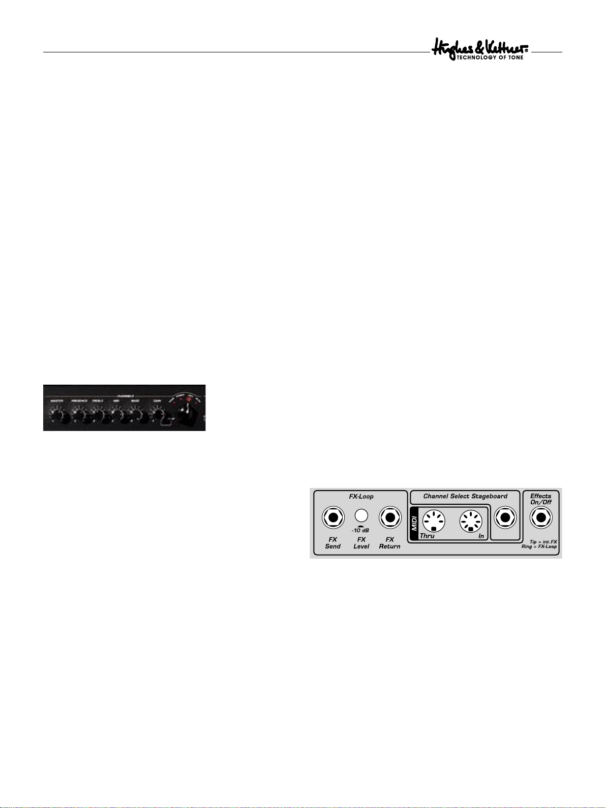
4.4 FX LOOP
SmartLoop™ is a special effects routing circuit offering a switchable
Parallel/Serial effects loop for patching in external ef fect devices.
Its status is stored in each Preset, that is, whether it is on or off and
configured in a parallel or serial circuit.
18
5.1 EFFECTS ON/OFF
®
This port accepts the two-way Hughes & Kettner
FS-2 footswitch.
Button 1 switches internal effects; button 2 the external effects loop.
The FS-2’s LED lights up to indicate ef fects are active and the
FX ON
button is engaged. It does not light up if the internal effects are
bypassed or the
Note: The footswitch deactivates the FX ON button on the front panel!
When a footswitch is connected, it always has priority. The current
status of the footswitch is valid when switching Channels, irrespective
of the switching status stored in the preset! The front panel FX ON
button now serves as an LED display indicating the status of the
footswitch.
FX ON button is switched off.
5.2 CHANNEL SELECT
If you ever leave your MIDI board behind, this flexible fall-back
connector for footswitches will help get you through the gig. It lets
you switch remotely between two Channels, say
using standard one-way footswitches such as the Hughes & Kettner
FS-1. A two-way footswitch such as the Hughes & Kettner
CLEAN and ULTRA,
®
FS-2
®
may also be connected. In this case, button 1 is responsible for the
Channels, and button 2 is disabled.
four-way Hughes & Kettner
Kettner® Trilogy and Matrix amp. It lets you switch all four Channels.
SWITCHBLADE even accepts the
®
FS-4 footswitch that ships with Hughes &
Page 6
Switchblade
Note: The footswitch changes the Channels only, and not presets.
That is, it activates the most recent Channel settings and it does not
switch effects.
5.3 FX LOOP
If you wish to use an external effect device, you can insert it into the
FX LOOP.
5.3.1 FX SEND
Connect this jack to your effects processor‘s input jack.
5.3.2 FX LEVEL
This button cuts the
FX RETURN’s input sensitivity by 10 dB to match the FX Loop to the
FX SEND’s output level by 10 dB and boosts the
effect device’s input level. Press this button when using processors
designed to handle instrument levels.
5.3.3 FX RETURN
Connect this jack to your effects processor‘s output.
5.4 MIDI
SWITCHBLADE is MIDI-enabled, meaning that it communicates with
other MIDI devices.
5.4.1 MIDI IN
®
Connect the included Hughes & Kettner
FSM 432 or any other MIDI
sender to this port so that you can select and switch Presets remotely.
Though this is a seven-pin port, you can connect a standard five-pin
MIDI cable. The two additional terminals serve to supply phantom
power to the FSM 432.
in parallel, the resulting resistance (R) is calculated by multiplying the
two individual resistances and dividing their product by the sum of the
individual resistances. Use the following formula to do this:
R = ( R1 x R2 ) / ( R1 + R2 )
Take as an example a one 8-ohm and one 16-ohm cabinet:
R = ( 8 x 16 ) / ( 8 + 16 )
R = 128 / 24
R = 5.33
The cabinets’ impedance may never be lower than the amp’s output
impedance, so this combination must be connected to the 4-ohm
output. However, we strongly advised against configuring setups with
mismatched cabinets, and highly recommend using combinations of
cabinets with the same impedance!
6 MIDI Control and Programming
6.1 FSM 432
The included Hughes & Kettner
control serving to select the 128 memory slots conveniently arranged
in 32 Banks of four presets each. You can easily configure setups any
way you wish, say by assigning the four presets of a bank to a song.
®
FSM 432 MIDI board is a remote
english
5.4.2 MIDI THRU
This port forwards signals patched into the
MIDI IN port to other
devices. You can connect any external MIDI-enabled signal processor
or any MIDI receiver that you wish to switch synchronously with
SWITCHBLADE.
5.5 SPEAKERS
SWITCHBLADE offers separate outputs for all standard impedances:
You have 1 x 4-ohm, 1 x 8/2 x 16-ohm, and 1 x 16-ohm outputs at
your disposal. Always ensure the impedance (that is, the ohm value) is
correct. Mismatches can corrupt the sound (high-impedance speaker
connected to a low-impedance output) and harm the amp (lowimpedance speaker connected to a high-impedance output).
Note: You may of course connect several cabinets to one port, even
if they have different impedances. Usually speaker cabinets are
connected in Parallel. Two cabinets of the same impedance connected
in Parallel have half the impedance of a single cabinet. For example, if
you have two 8-ohm cabinets, you must connect these to the 4-ohm
output. If you connect two cabinets with different impedances (R1, R2)
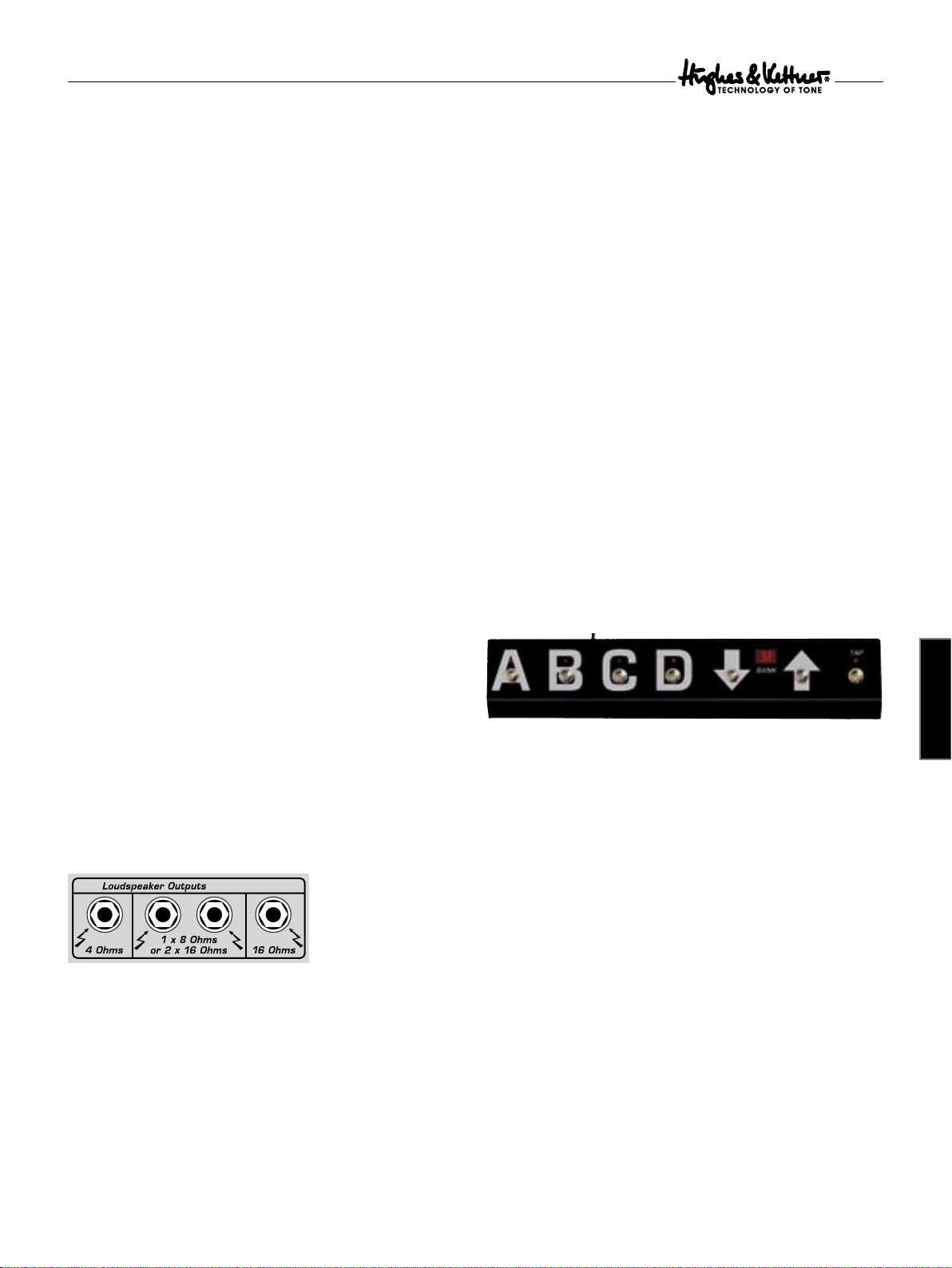
6.1.1 PRESET A B C D
Presets within a bank can be activated directly, that is, switching from
A to B within the same bank occurs immediately. The LED above the
A,B,C,D buttons indicates the preset.
6.1.2 BANK UP/DOWN
If you want to call up a preset in another bank, you can select the bank
via UP and DOWN while continuing to play using the current preset.
The number of the bank is indicated in the display, and it flashes until
you select a preset via A,B,C,D. Not until then will
SWITCHBLADE load
the new preset.
DIRECT MODE is available if you wish to trigger a direct program
change via bank Up/Down. In this mode, the FSM 432 will not wait for
your input, instead switching immediately, for example, from preset
B in bank 16 to preset B in bank 17 (
UP) bank or 15 (DOWN). Direct
Mode is activated as follows:
• Press and hold TAP, and then press PRESET A.
• First release PRESET A, and then TAP: The decimal point in the
display lights up.
Follow the same sequence to deactivate
than permanent,
DIRECT MODE is automatically deactivated when you
DIRECT MODE. Volatile rather
power SWITCHBLADE down!
19
Page 7
Switchblade
6.1.3 TAP
The TAP function gives you a very fast and convenient option for
changing the Delay’s
on stage: Simply tap your foot on the
groove to match delay Time to the tempo. The ef fect adopts the new
time after the second tap. The
in time with the beat to give you a visual indication of the delay time.
Note: The TAP function works only when the DELAY is active. If the
DELAY is off, the effect will not adopt your TAP tempo.
6.1.4 Switching External Devices via the
FSM 432, Setting the MIDI Send Channel
If you wish to switch devices connected to
– say, a MIDI effect device – using the FSM 432, ensure the effect
device is set to the FSM 432’s MIDI Channel or to
device’s manual for more info.
To set the FSM 432’s MIDI Send Channel, proceed as follows:
• Turn SWITCHBLADE on while pressing the FSM 432’s PRESET A
button. The display flashes.
• Release button A. Use UP/DOWN to view and set the MIDI Channel
to a number between 1 and 16.
• Quit and store by pressing the PRESET A button.
Caution: If SWITCHBLADE and FSM 432 are not set to the same
MIDI channel, the amp will not respond to program changes!
Activating OMNI solves the problem in the event of an “emergency.”
See chapter 6.2 to learn more.
Note: If an external effect device is connected to MIDI THRU and
you want to switch Switchblade and the effect device simultaneously
with the same program change command, you must configure
Switchblade’s Store function and program this device accordingly.
Note: The table above should be big help if you wish to switch the
Presets of a device connected to the MIDI THRU directly via the
FSM 432. It shows the program changes sent by the bank/preset
combination. Please bear in mind that some MIDI devices switch
program 1 via program change command 0. If this is the case with
your outboard gear, simply add a 1 to each value indicated in this
table to activate the desired program.
TIME parameter. TAP comes in particularly handy
TAP button in Time with the
TAP LED flashes for about five seconds
SWITCHBLADE MIDI THRU
OMNI. Consult the
Bank
Preset
Programchange
Number
Bank
Preset
Programchange
Number
Bank
Preset
Programchange
Number
Bank
Preset
Programchange
Number
1 A 0 9 A 32 17 A 64 25 A 96
1 B 1 9 B 33 17 B 65 25 B 97
1 C 2 9 C 34 17 C 66 25 C 98
1 D 3 9 D 35 17 D 67 25 D 99
2 A 4 10 A 36 18 A 68 26 A 100
2 B 5 10 B 37 18 B 69 26 B 101
2 C 6 10 C 38 18 C 70 26 C 102
2 D 7 10 D 39 18 D 71 26 D 103
3 A 8 11 A 40 19 A 72 27 A 104
3 B 9 11 B 41 19 B 73 27 B 105
3 C 10 11 C 42 19 C 74 27 C 106
3 D 11 11 D 43 19 D 75 27 D 107
4 A 12 12 A 44 20 A 76 28 A 108
4 B 13 12 B 45 20 B 77 28 B 109
4 C 14 12 C 46 20 C 78 28 C 110
4 D 15 12 D 47 20 D 79 28 D 111
5 A 16 13 A 48 21 A 80 29 A 112
5 B 17 13 B 49 21 B 81 29 B 113
5 C 18 13 C 50 21 C 82 29 C 114
5 D 19 13 D 51 21 D 83 29 D 115
6 A 20 14 A 52 22 A 84 30 A 116
6 B 21 14 B 53 22 B 85 30 B 117
6 C 22 14 C 54 22 C 86 30 C 118
6 D 23 14 D 55 22 D 87 30 D 119
7 A 24 15 A 56 23 A 88 31 A 120
7 B 25 15 B 57 23 B 89 31 B 121
7 C 26 15 C 58 23 C 90 31 C 122
7 D 27 15 D 59 23 D 91 31 D 123
8 A 28 16 A 60 24 A 92 32 A 124
8 B 29 16 B 61 24 B 93 32 B 125
8 C 30 16 C 62 24 C 94 32 C 126
8 D 31 16 D 63 24 D 95 32 D 127
6.2 Setting Switchblade’s MIDI
Channel and Switching OMNI
Press the
SERIAL button longer than two seconds when SWITCHBLADE
is in normal operating mode, and the
ON/OFF
ORIGINAL VALUE LED will start
flashing. This assigns special programming functions to the amp’s LEDs
and buttons:
20
FX ON
Now serves as a +1/
UP button for setting the MIDI Channel.
Serial
Now serves as a -1/
DOWN button for setting the MIDI Channel.
Store
OMNI ON/OFF switches. If the STORE button (OMNI On) lights up,
SWITCHBLADE responds to all incoming program changes, irrespective
of the MIDI Channel over which they are sent. If the light on the button
is extinguished (
OMNI OFF), it responds only to messages sent via the
defined MIDI Channel.
Page 8
Switchblade
FACTORY SETTING: MIDI CHANNEL = 1, OMNI = ON
Note: OMNI ON is helpful if you are unsure via which channel
a connected MIDI device sends its messages.
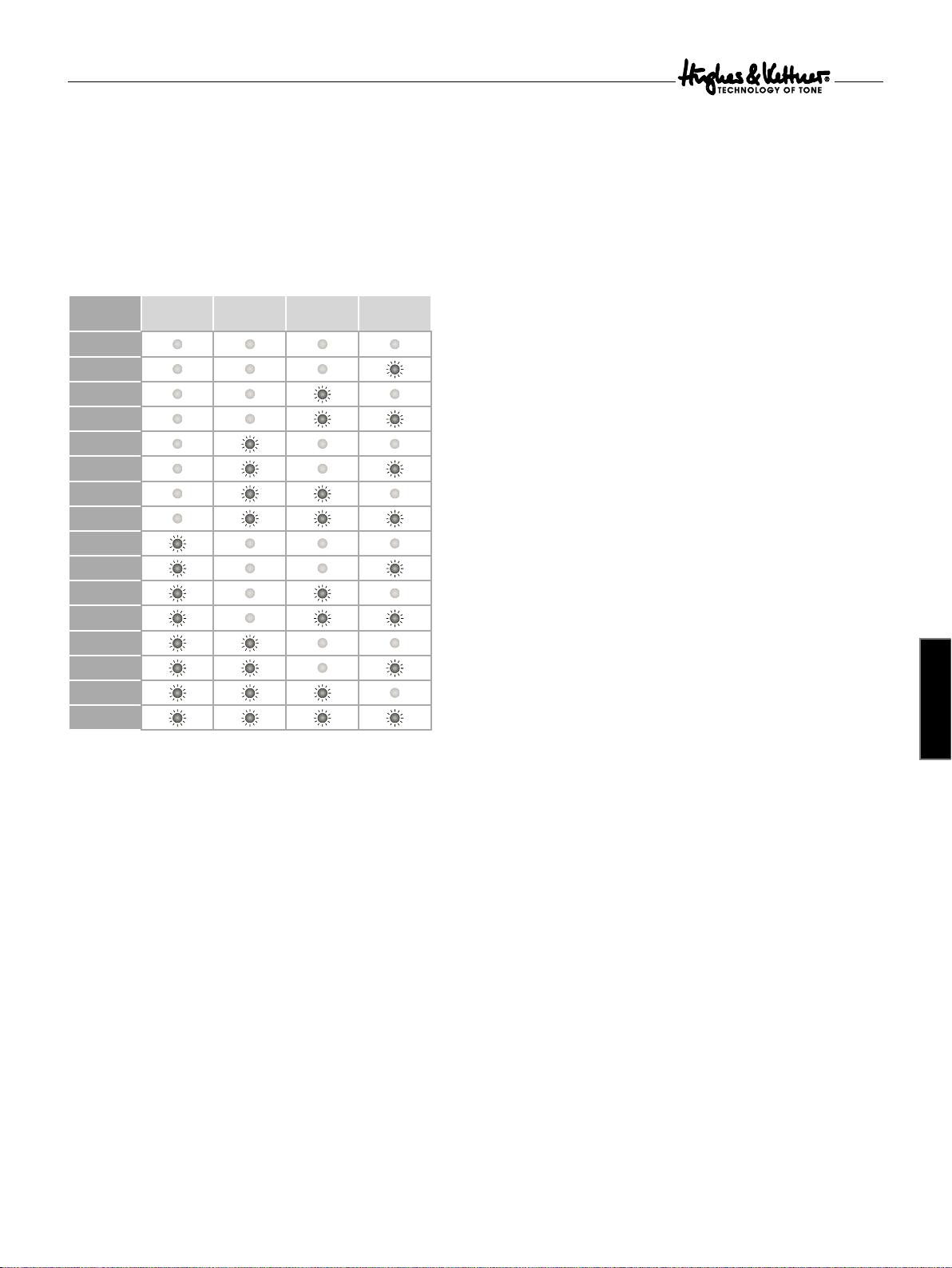
During the MIDI setup routine, the LEDs that normally indicate the
preamp Channel indicate the MIDI Channel. The following table MIDI
Channel lists the MIDI Channel settings in what is called binary code:
MIDI-Kanal Boost Clean Lead Ultra
1
2
3
10
11
12
13
14
15
16
4
5
6
7
8
9
Press and hold SERIAL for a few moments to quit the MIDI setup
routine and store the settings. The amp returns to its most recent
operating status (normal mode).
6.3 Factory Settings and Factory Reset
A factory reset is a seldom needed feature. Nevertheless, be sure to
read the explanation carefully to ensure you don’t accidentally delete
your presets.
6.4 Storing Settings/Programming
You have two options for storing a preset to one of the 128 memory
slots: Select a new memory slot via MIDI (6.4.1) or overwrite the
preset directly at the device (6.4.2).
6.4.1 Selecting a New Memory Slot via MIDI Learn
• Press the STORE button briefly; it lights up to signify that it is armed
(MIDI Learn).
• Select a MIDI bank from 1 to 32 on the FSM 432; it flashes to signify
that the FSM 432 is waiting for input via one of the four preset
buttons A to D.
• Engage preset button A,B,C or D; the board stops flashing, the light
STORE button extinguishes, and the preset is stored.
on the
Caution: When the FSM 432 is in DIRECT MODE (see chapter 6.1.2),
a BANK UP/DOWN command also triggers the storage process! We
recommend deactivating Direct Mode when programming to prevent
inadvertent overwriting of presets.
Note: Here’s how to proceed for other manufacturers’ MIDI boards
and MIDI-enables devices: Arm
STORE button and selecting the desired memory slot. As soon as
SWITCHBLADE receives a valid program change command, the STORE
button extinguishes and the preset is stored.
SWITCHBLADE by engaging the
If an error occurs (the amp remains armed), you can cancel the storage
process by pressing
STORE again.
6.4.2 Overwriting Presets Directly at the Device
There is an easier way to overwrite the most recently selected preset
than going from the amp to the MIDI board and back after every edit:
Press and hold the
about two seconds). The
flash to confirm. Then you can release the
STORE button until its light extinguishes (after
ORIGINAL VALUE and the Channel LEDs also
STORE button and your
settings are stored.
7 Replacing Tubes, Service
and Preventive Maintenance
english
6.3.1 Triggering a Factory Reset
If you press
STORE and FX SERIAL simultaneously while powering the
amp, all settings are reset, including the 128 MIDI-switchable presets
and the basic MIDI configuration.
6.3.2 Factory Presets and Basic MIDI Configuration
The A to D presets of all banks correspond the channel settings; that is,
all 32 banks have the same settings: Preset A corresponds to Clean, B
to Crunch, C to Lead, and D to the Ultra Channel.
The basic MIDI configuration is:
• OMNI ON • MIDI Channel: 1
• FX ON is switched off. • SERIAL is deactivated.
CAUTION: This procedure is a last-resort option! It irrevocably wipes
out all stored settings.
SWITCHBLADE is factory-loaded with EL34 and 12AX7 tubes. Once
they’ve been burned in – that is, operated continuously under a load –they
are subjected to a rigorous selection process. Their electrical specs and
mechanical status (microphonics) are checked, and then they are installed
in an amp and their sonic performance is auditioned. One of the most
important steps in this process is tube matching, whereby tubes with the
same characteristics are teamed up in matched sets of power tubes.
When to Replace Tubes
The tubes in
SWITCHBLADE are exemplary in terms of quality,
workman-ship and long service life. Nonetheless, tubes show definite
signs of wear when their service life is nearing its end. Telltale signs are
increased microphonics, noise and hiss, muddier tone through loss of
high-end frequencies, degraded performance, etc. Take these indications
seriously and replace old tubes. Not only do these side effects take their
toll on sound quality, they also indicate the aging tube will soon fail!
21
Page 9
Switchblade
Note: Replacing tubes for experimentation purposes is not
recommended. Installing the wrong tubes will damage the amp and
cost you a lot more than you bargained for in repair costs.
Before you start swapping tubes, ask yourself these questions:
• Was the fault or failure of the tube caused by the tube itself or by a
flawed peripheral device or component, perhaps a defective speaker
cable? If you don’t get to the bottom of the problem and remedy it,
it may crop up again even after you replace the tubes.
• Did the Mains voltage fluctuate or spike while the amp was on? In
all-tube amps, over-voltage surges in the Mains net can certainly
cause drop-outs. Over-voltages are often caused by generators and
faulty high-current power circuits.
• Perhaps a fuse blew even though none of the tubes is actually
defective? An old fuse, tube de-ionization or Mains voltage power
surges may have triggered the fuse.
Things to Bear in Mind When Replacing Tubes
Replacing tubes is a job best left to qualified professionals!
Accordingly, the following guidelines are addressed and apply to
qualified service technicians only:
• Pull Switchblade’s Mains plug and allow for a discharge time of at least
two minutes before removing the chassis from the rear of the amp.
• Once the chassis has been removed, carefully ease the tubes out of
their sockets.
• A single power tube may only be replaced if the replacement tube
precisely matches the original, that is, the old and new tubes’
characteristics are identical.
• When a new matched set of power tubes with characteristics
identical to the old set is installed, it is not absolutely necessary to
re-bias the amp.
• The amp must be biased when a replacements set’s characteristics do
not match the original set’s. This requires experience and extensive
working knowledge in measuring techniques, which is why this is a
job for qualified technicians with tube amp tuning experience.
How to Prolong Tube Life
• Never operate Switchblade without connecting a load (loudspeaker)!
• Never connect speaker cabinets with an impedance that is too high
or low!
• Always use high-quality, heavy-duty speaker cords that won’t crimp!
• Use the STANDBY switch for short breaks!
• Avoid exposing the amp to vibrations, especially when it’s powered up.
• Switch the amp off well before transporting it to allow tubes to cool
off completely.
• Make sure all peripheral devices and connecting cords are in a state
of good repair!
• Ensure air can circulate freely around the amp’s ventilation slots at
all times!
• Never expose Switchblade to extreme heat or cold!
• Prevent the intrusion of dust and moisture!
• Always check peripheral gear’s specs to ensure these accessories are
suitable for the amp.
• Never connect devices with high output signal Levels to
Switchblade’s Input.
• Never operate the amp with Mains power that is too high or too
22
low. When in doubt ask the venue’s sound technician or facility
engineer.
• Refrain from DIY repairs! Also have a qualified technician replace
internal fuses.
8 Troubleshooting
Mains connection: SWITCHBLADE
won’t power up when you switch it on.
• It‘s not getting AC power. Check the Mains cord to see if it is
connected and firmly seated.
• The Mains fuse is defective. Ensure it is replaced with another fuse
bearing the same rating.
• The local Mains voltage does not match Switchblade’s operating voltage
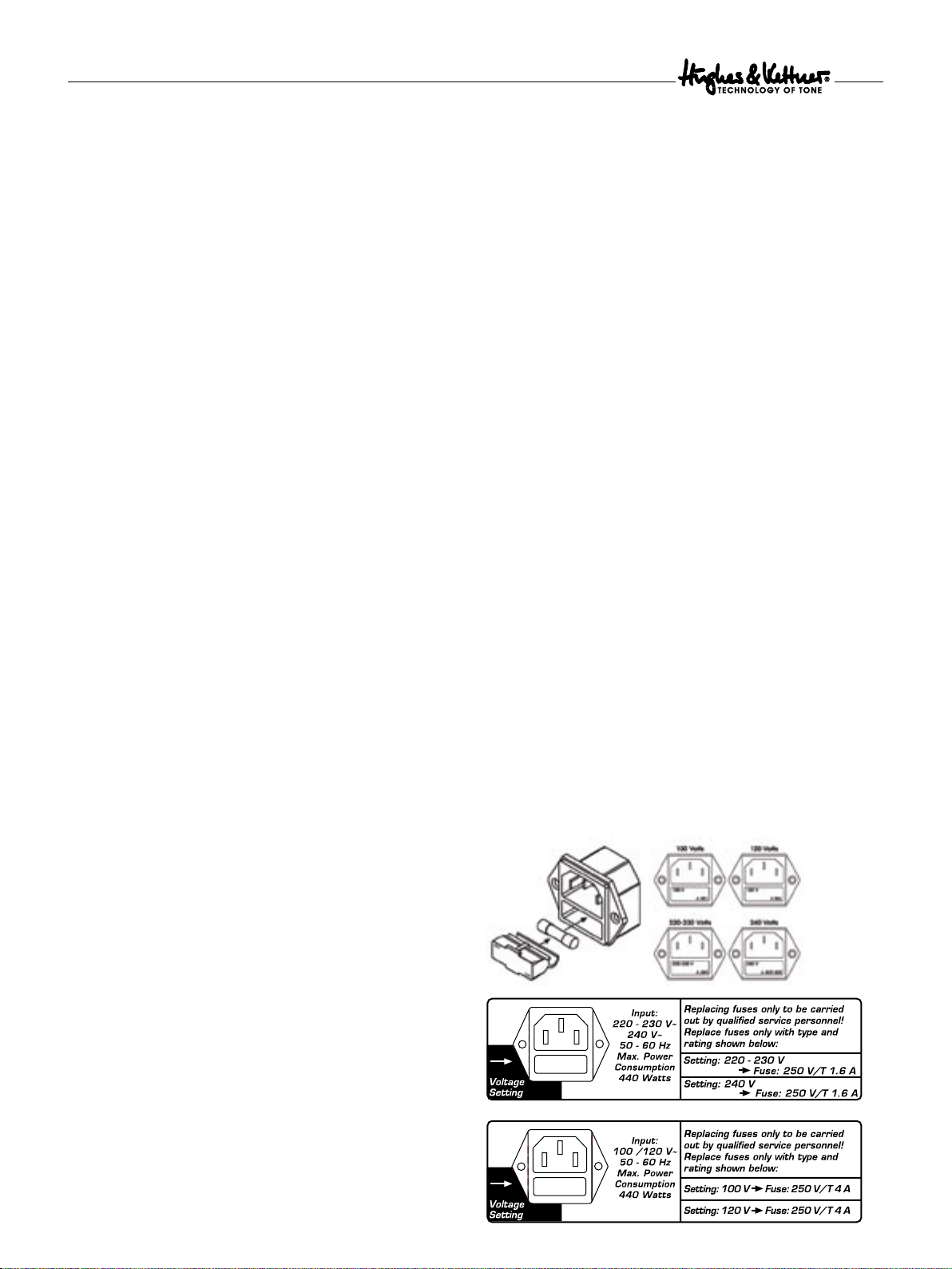
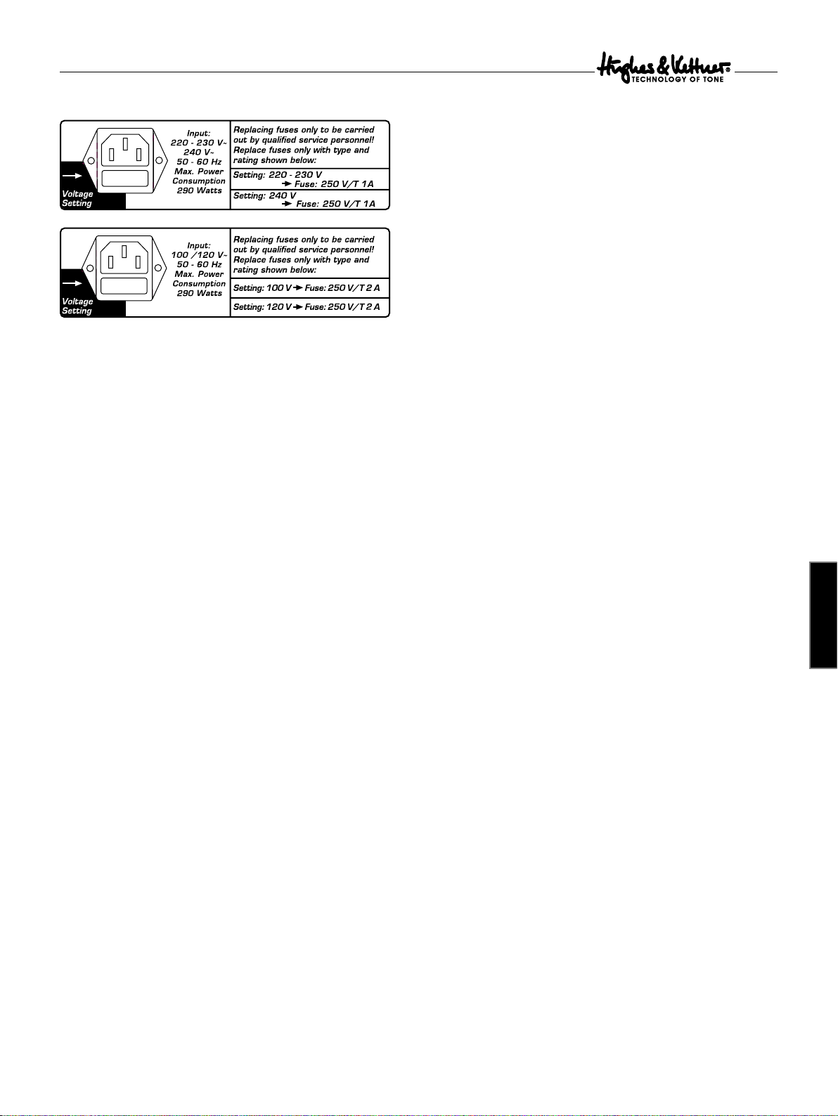
Available Voltages and How to Adapt Them
Switchblade ships in two versions rated for 110/120V and 220-240V.
You will find the rating indicated on the housing above the Mains
socket. Both models offer two operating voltages that are selected
using the voltage selector integrated in the Mains socket. Ensure that
the Mains voltage matches the voltage rating appearing in the voltage
selector window. This value is legible when the amp is in the standard
operating position, that is, placed right side up. The upright number
indicates the currently selected voltage, and the inverted number
indicates the alternative voltage. Check also the fuse ratings to ensure
they match the ratings indicated on the rear panel.
Voltage selection and fuse replacement may be performed by
experienced service technicians only. Accordingly, the following notes
are addressed exclusively to service technicians:
• Use a small flat screwdriver to remove the voltage selector from the
Mains socket.
• If the fuse is defective, replace it with a fuse bearing the specified rating.
• Turn the voltage selector and insert it back into the port so that the
desired Mains voltage rating is legible and appears at the top left
(next to the “Voltage Setting” arrow).
HEAD / COMBO 100
Page 10
Switchblade
COMBO 50
Switchblade is connected
properly, but no sound is audible.
• The guitar’s VOLUME knob is turned all the way down.
• The amp is set to STANDBY.
• The amp’s VOLUME knob is turned all the way down.
• The effects loop is active and set to SERIAL, but no ef fect device is
connected.
• The anode fuse has blown. Ensure that it is replaced with a fuse of
the same rating.
• The fuse for the tube heating tripped (the tubes don’t glow). Ensure
that it is replaced with a fuse bearing the same rating.
The amp makes ringing noises
when played and tends to Feedback.
• One or several tubes are microphonic. Replace the defective tube
with another of the same type.
Signs of tube wear such as increased microphonics and
noise, Treble loss, weak power output or muddy sound
begin reappearing just a few hours after replacing tubes.
• The wrong tubes were installed when old tubes were replaced or
the amp was not biased properly. Take the amp to a professional to
correct the problem.
The sound is washed out or muddy when you switch an
effects processor on.
• The signal processor provides a wet signal that is blended with
the dry or original signal. Depending on the type of effect, the
processor may be returning a dry signal back along with wet signal,
which causes phase cancellations when mixed to the dry signal in
Switchblade’s Parallel loop. To prevent this, set the effects loop
to SERIAL or turn the dry signal all the way down on the signal
processor.
english
23
Page 11
Switchblade
9 Technical Specifications
All level indications relate to 0 dBV (1V RMS).
9.1 Inputs
INSTRUMENT Input
Input: 6.3 mm (1/4”) jack
Type: unbalanced
Input impedance: 1 MW
Sensitivity: - 50 dB (Clean Channel)
Max. Input Level: 0 dB
FX Return
Input: 6.3 mm (1/4”) jack
Type: unbalanced
Input impedance: 48 k W
Max. sensitivity: -10dB button engaged: - 21 dB,
disengaged: - 11 dB
Max. Input Level: -10dB button engaged: + 0 dB,
disengaged + 10 dB
MIDI IN
Port: DIN 45 329 (7-pin )
Data reception: Program change data, Tap Delay function
Channels: 16, Omni mode
Power supply: 15V DC max. 200mA, pin 6 = positive,
pin 7 = negative
9.2 Outputs
FX Send
Output: 6.3 mm (1/4”) jack
Type: unbalanced
Output impedance: 2.2 k W
Output Level: + 3 dB
Max. output Level: -10dB button engaged: - 2 dB,
disengaged: + 8 dB
MIDI THRU
Port: DIN 45 328 ( 5-pin)
Data handling: All data sent to MIDI IN are patched
out unchanged.
9.3 General Electrical Data
Switchblade 100 Head/Combo Switchblade 50 Combo
Max. current consumption:
440 watts 290 watts
Max. power consumption:
1.75A @ 240 volts 0.97A @ 240 volts
1.89A @ 220-230 volts 1.07A @ 220-230 volts
3.50A @ 117-120 volts 2.00A @ 117-120 volts
3.95A @ 100 volts 2.15A @ 100 volts
Mains voltage tolerance range: +/- 10 %
External fuses (anode):
1 x T 630 mA 1 x T 400 mA
Internal fuses:
1 x TT 10 A Slo Blo 1 x TT 10 A Slo Blo
2 x T 630 mA 2 x T 630 mA
Mains fuse (5 x 20 mm):
Europe: (variable: 220 V-230 V / 240 V
1 x 250 V / T 1.6 A 1 x 250 V / T 1 A
USA/Canada/Asia:( variable: 100 V / 120 V)
1 x 250 V / T 4 A 1 x 250 V / T 2 A
Ambient operating temperature range:
0 °C to + 35 °C 0 °C to + 35 °C
9.4 General Mechanical Data
100 Head 100 Combo 50 Combo
Dimensions: (including corners, handles, feet)
Width: 750 mm 647 mm 600 mm
Height: 280 mm 500 mm 500 mm
Depth: 258 mm 285 mm 285 mm
Weight: 17.6 kg 30.3 kg 22.8 kg
Speaker Outputs
6.3 mm (1/4") jacks: 1 x 4 ohms, 2 x 16 ohms / 1 x 8 ohms,
1 x 16 ohms
Speaker
100 Combo 2 x 12" Eminence® Rockdriver 60
50 Combo 1 x 12" Eminence® Rockdriver 60
24
Page 12
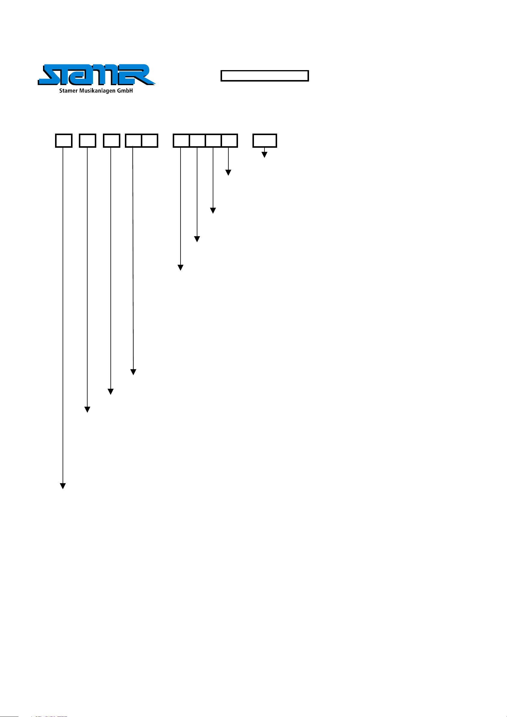
DRAWING-NUMBERS
EXAMPLE
HK0106-EX-R01-1A
VERSION
SERIAL NUMBER
DEPARTMENT:
R = R&D
REVISION
PROJECT-NR.:
HK = HK AUDIO
HU = HUGHES&KETTNER
MP = MINDPRINT
CHARACTER:
BL = SHEET METAL / BLECH
EX = EXPLODED DRAWING / EXPLOSIONSZEICHNUNG
HZ = CABINET / HOLZGEHÄUSE
KU = PLASTIC / KUNSTSTOFF
LP = PCB / LEITERPLATTEN
SO = MISCELLANEOUS / SONSTIGES
SP = SCHEMATIC / SCHALTPLÄNE
TR = TRANSFORMER / TRANSFORMATOR
GK = WIRING DIAGRAM / GERÄTEVERKABELUNG
Page 13
Stand
W
Y
r
Standard for single wire confection.
16 B 150 638 I - 485 W Z I 1015
style 1015 according UL specifications
I = completely insulated with black shrinktube or appropriate sleeve
IT = partly insulated; only crimp connection insulated.
no marking = without insulation
Z = with additional junction
no marking = without additional junction
W = angled faston
no marking = straight faston
17. Jun 04
Faston connector brass tin-plated DIN 46245
638 = 6,3 * 0,8 [mm]
488 = 4,8 * 0,8 [mm]
485 = 4,8 * 0,5 [mm] if fully insulated (I) insulation with blue shrinktube
if partly insulated (IT) use IF 602 485 .
288 = 2,8 * 0,8 [mm]
285 = 2,8 * 0,5 [mm] if fully insulated (I) insulation with blue shrinktube
if partly insulated (IT) use IF 602 485
abiso = 5mm bared and tin-plated (teilabzug)
text for special constructions, (for example. 4mm ringshaped faston)
the larger faston connector always mentioned at first. (Nathan drawing number controlling)
lenght in mm within a 50 mm raster
colour
B = black (phase conductor)
R = red
BR = brown
BL = blue (neutral conductor)
= white
G = yellow-green (ground bonding/ earthing connection)
cross section
16 = AWG 16 (prefered usage)
Q1.5 = H07VK 1,5mm² (prefered usage)
wire designation:
P + lfd Nr. = AWG single wire black, red, blue, brown or white
E + lfd Nr. = AWG single wire green- yellow
L + lfd N
FQL + lfd Nr. = crossover wiring H07VK
Regarding special wirings like wiring harness or similar, drawings will be prepared and appropriate
. = twisted AWG double wire, lenght specification always in twisted condition
drawing numbers will be stored in the article archive.
Page 14

Service Documents
Confidential, for authorized service technicians only!
Do not disclose this information to or share these documents with third parties.
TECHNICAL SERVICE:
Stamer Musikanlagen GmbH • Magdeburger Str. 8 • 66606 St.Wendel • Germany
Music & Sales P.E. GmbH • Leipziger Str. 3 • 66606 St.Wendel • Germany
HU1605
SwitchBlade
50 Combo
Page 15

6E 972041
10
9E 974418
4 E 970788
5E 972013
HU1605-BL-R02-1D
10E 976073
8E 974355
INDEX CHANGES
HU1605-EX-R02-1A
8
1 E 502193 (230V)
E 502194 (100-120V)
HU1605-EX-R03-1A
7 E 974010
11 E 994197
8
2E 959073
3 E 959076
TITLE:
HU1605-SWITCHBLADE 50
EXPLODED DRAWING COMPLETE
66606 St. Wendel / Germany
RESP.
DRAWING-NO.:
DRAWN BY:
CHECKED BY:
MATERIAL:
FILENAME:
HU1605-EX-R01-1A
C. LORIS 1
HU1605-EX-R01-1A-COMPLETE
FINISH:
VERSION:
DATE:
25.08.2006
DATE:
OBERFLÄCHE
REVISION:
PAGE:
2
A1
PAGES
Page 16

pos. part-no. 1 part-no. 2 part-no. 3 description Beschreibung quantity
1 502193 (230V) 502194 (100-120V) SWITCHBLADE 50 chassis SWITCHBLADE 50 Chassis 1
2 959073 SWITCHBLADE 50 wooden cabinet complete SWITCHBLADE 50 Holzgehäuse komplett 1
3 959076 MIDI Footswitch FSM-432 MIDI Footswitch FSM-432 1
4 970788 sheet metal SWITCHBLADE 50 rear panel Blech SWITCHBLADE 50 Rückwand 1
5 972013 Insulation Sleeve IB6 Isolierbuchse IB6 2
6 972041 rubber punching 25x25x15 Zellkaut. -Stanzteil 25x25x15mm 2
7 974010 hexagon socket head cap screw, M6x20, black Inbusschraube M6*20 sw 4
8 974355 cross recessed panhead tapping screw with collar, 3.9x30, black Blechschr. KFR-Kopf 3,9* 30 sw 14
9 974418 cross recessed countersunk tapping screw, 4.2x38, zinc plated Blechschraube Flachsenk. 4,2*38 vz 2
10 976073 strap handle ´Hughes & Kettner´ Bandgriff ´Hughes & Kettner´ 1
11 994197 Eminence 12" Guitar Speaker, Switchblade (Ref.: 05-12-037) Eminence 12"Guitar Speaker, Switchblade (Ref.: 05-12-037) 1
INDEX CHANGES
RESP.
66606 St. Wendel / Germany
DRAWING-NO.:
DRAWN BY:
CHECKED BY:
MATERIAL:
FILENAME:
HU1605-EX-R01-1A
C. LORIS 2
HU1605-EX-R01-1A-COMPLETE
TITLE:
HU1605-SWITCHBLADE 50
EXPLODED DRAWING COMPLETE
VERSION:
DATE:
25.08.2006
DATE:
FINISH:
OBERFLÄCHE
REVISION:
PAGE:
2
A1
PAGES
Page 17

12E C90177
1
11E C90177
15
HU1605-HZ-R01-1E
14E C90177
3E 972068
13E C90177
2E 970646
1
15
9E 980229
6E 976145
5
8
15
15
1E 959073
7E 976146
8 E 976147
INDEX CHANGES
4E 976059
10E C90177
5E 976092
TITLE:
HU1605-SWITCHBLADE 50
EXPLODED DRAWING CABINET
66606 St. Wendel / Germany
RESP.
DRAWING-NO.:
15E C90177
DRAWN BY:
CHECKED BY:
MATERIAL:
FILENAME:
HU1605-EX-R02-1A
C. LORIS 1
HU1605-EX-R02-1A-CABINET
FINISH:
VERSION:
DATE:
25.08.2006
DATE:
n/a
REVISION:
PAGE:
2
A1
PAGES
Page 18

pos. part-no. 1 part-no. 2 part-no. 3 description Beschreibung quantity
1 959073 wooden cabinet Matrix 50 Combo Holzgehäuse Matrix 50 Combo 1
2 970646 sheet metal Warp X ventilation grille RAL 9005 Blech Warp X Lüftungsgitter RAL 9005 1
3 972068 clothing black/silver Bespannstoff schwarz/silber 1
4 976059 rubber foot conical D30-23/H15mm Gummifuss konisch D30-23/H15mm 4
5 976092 corner CR-4 Ecke Corner CR-4 2
6 976145 corner CR-6 left Ecke CR-6 links 1
7 976146 corner CR6 right Ecke CR-6 Rechts 1
8 976147 corner CR-7 Ecke Corner CR-7 f. 15mm Mat.par 4
9 980229 logo silver, 3 parts Logo 3-teilig Silber 1
10 C90177 ABC-Spax-S screws for backwall, 4x20, black Rückwandschraube, 4*20 sw 4
11 C90177 cross recessed panhead tapping screw with collar, 3.9x30, black Blechschr. KFR-Kopf 3,9* 30 sw 4
12 C90177 ABC-Spax S, countersunk head, Pozidrive, 5x40, zinc plated Spax Senkkopf, 5*40 vz 8
13 C90177 pronged T-nut, M6x9, black Einschlagmutter Stahl schwarz M6x9mm 4
14 C90177 ABC-Spax S, countersunk head, Pozidrive, 3x12, black Spax Senkkopf, 3*12 sw 8
15 C90177 cross recessed panhead tapping screw with collar, 3.9x13, black Blechschr. KFR-Kopf 3,9*13 sw 20
part-no.: C90177 is a screw-set with all fittings used in HU1605-SWITCHBLADE 50 wooden cabinet
INDEX CHANGES
RESP.
66606 St. Wendel / Germany
DRAWING-NO.:
DRAWN BY:
CHECKED BY:
MATERIAL:
FILENAME:
HU1605-EX-R02-1A
C. LORIS 2
HU1605-EX-R02-1A-CABINET
TITLE:
HU1605-SWITCHBLADE 50
EXPLODED DRAWING CABINET
VERSION:
DATE:
25.08.2006
DATE:
FINISH:
n/a
REVISION:
PAGE:
2
A1
PAGES
Page 19

6E 944011
21 E 974007
37 E 975416
5E 944007
8 E 944029
15 E 966077
16
7E 944019
1
24E 974102
3E 544086
23
17 E 966079
16 E 966078
9 E 948030
33 E 974384
21E 974007
39E 976007
26
20E 972041
23
26
22E 974075
34 E 974417
1 E 544084
HU1605-EX-R04-1A
29 E 974197
1
25 E 974110
30 E 974230
27E 974137
11 E 950035
36E 974520
INDEX CHANGES
23E 974100
21
26E 974135
32
2E 544085
38E 976003
23
21
12 E 952014
4 E 932018 (220-240V)
28E 974154
10 E 948040 (230V)
32
RESP.
36
E 932022 (100-120V)
E 948039 (100-120V)
18 E 970786
HU1605-BL-R01-1H
13E 958189
19 E 970787
HU1605-BL-R03-1C
31 E 974286
14 E 958191 (220-230/240V)
E 958192 (100-120V)
32 E 974354
35 E 974494
66606 St. Wendel / Germany
DRAWING-NO.:
DRAWN BY:
CHECKED BY:
MATERIAL:
FILENAME:
HU1605-EX-R03-1A
C. LORIS 1
HU1605-EX-R03-1A-CHASSIS
TITLE:
HU1605-SWITCHBLADE 50
EXPLODED DRAWING CHASSIS
VERSION:
DATE:
23.08.2006
DATE:
FINISH:
n/a
REVISION:
PAGE:
4
A1
PAGES
Page 20

pos. part-no. 1 part-no. 2 description Beschreibung quantity
1 544084 Switchblade 50 Preamp 1x12'' Switchblade 50 Preamp 1x12'' 1
2 544085 SwitchBlade 50 FX board SwitchBlade 50 FX Board 1
3 544086 SwitchBlade 50 Power Amp 1x12'' SwitchBlade 50 Power Amp 1x12'' 1
4 932018
(220-240V)
932022
(100-120V)
microfuse slowblow 5*20 IEC 127; 1,0A (for
220-240V); 2,0A (for 100-120V)
Feinsicherung 5*20 IEC 127; 1,0A Träge
(für 220-240V); 2,0A Träge (für 100-120V)
1
5 944007 tube ECC83-CZ Tesla Röhre ECC83-CZ Tesla 2
6 944011 Tubeclamp Röhrenhaltedraht VRA 10.01 2
7 944019 Tube Bracket 6L6GC Röhrenhalteklammer 6L6GC 2
8 944029 power tube EL34B China Endst. Röhre EL34B STR China 2
9 948030 FPLR lens for PilotLight blue FPLR Linse für PilotLight blau 1
10 948040
(230V)
948039
(100-120V)
fuse case for power inlet SI-Einsatz Netzbuchse 1
11 950035 mains switch, rocker, on-on Netzschalter-Kipphebel-on-on 2
12 952014 power inlet MS3 SKT MS-3 Euronetzbuchse MS3 SKT MS-3 1
13 958189 power audio transformer TI-053474 50W Übertrager TI-053474 50W 1
14 958191
(220-230/240
958192
(100-120V)
mainstransformer TI-0532270 EU/UK;
TI053271 US/JP
Ringkerntrafo TI-0532270 EU/UK;
TI053271 US/JP
1
V)
15 966077 knob Modern Tube Knopf-Poti Modern Tube 1
16 966078 Chrome Knob big 18mm, straight knurled
Knopf Chrome Knob big 18mm 7
with dot
17 966079 Knopf Chrome Knob small 15mm, straight
Knopf Chrome Knob small 15mm 5
knurled with dot
18 970786 sheet metal SwitchBlade 50 chassis Blech SwitchBlade 50 Chassis 1
19 970787 sheet metal SwitchBlade 50 shielding
Blech SwitchBlade 50 Schirmblech 1
plate
20 972041 rubber punching 25x25x15 Zellkaut. -Stanzteil 25x25x15mm 1
21 974007 hexagon socket oval head screw, M3x6,
Linsenschr.m.Innens. M3*6 sw 10
black
22 974075 cross recessed panhead screw, M3x5, zinc
Linsenschraube M3x5 vz 2
plated
23 974100 toothed lock washer, D=3,2, AZ, black
Fächer-Scheibe az, 3,2 sw vz 9
zinc plated
INDEX CHANGES
RESP.
pos. part-no. 1 part-no. 2 description Beschreibung quantity
24 974102 hexagon nut, class 8, M3, zinc plated Sechskantmutter M3 vz 1
25 974110 self locking hexagon nut with plastic
Stopmutter M3 vz 1
insert, M3, zinc plated
26 974135 spread rivet, polyamid PA6, 4x5, black PA-Spreizniet D=4mm L=5mm 6
27 974137 RICHCO, PCB spacer, snap in, H=11.1mm Dist.Halter RICHCO H=11,1mm 2
28 974154 blind rivet steel standard, 3.0x8, black Blindniete Stahl schw. 3,0*8 2
29 974197 hexagon PCB spacer, type B, M3x8, zinc
Dist. Bol Innen/Außengew. M3*8 vz 1
plated
30 974230 knurled nut M12x1 Rändelmutter M12*1 1
31 974286 washer, form A, D=8.4mm, black Unterleg-Scheibe 8,4 sw 2
32 974354 toothed lock washer, D=8.4, AZ, black
Fächer-Scheibe az, 8,4 sw 4
zinc plated
33 974384 nut M14 brass Mutter FPLR Linse geschliffen 1
34 974417 sheet metal nut, D=4.2mm, yellow
Blechmutter 4,2mm vz 2
chromated
35 974494 hexagon nut, class 8, M8, black Sechskantmutter M8 sw 2
36 974520 hexagon socket oval head screw, M8x60,
Linsenschr.m.Innens. M8*60 sw 2
black
37 975416 hexagon PCB spacer, M3x17, zinc plated Dist. Bol 2*Innengew. M3*17 vz 2
38 976003 cable bushing 4*6*9 (mm) Kabeltülle 4*6*9 (mm) 1
39 976007 cable tie 2,5x100 (mm) Kabelbinder natur 2,5x100 (mm) 13
TITLE:
HU1605-SWITCHBLADE 50
EXPLODED DRAWING CHASSIS
66606 St. Wendel / Germany
DRAWING-NO.:
DRAWN BY:
CHECKED BY:
MATERIAL:
FILENAME:
HU1605-EX-R03-1A
C. LORIS 2
HU1605-EX-R03-1A-CHASSIS
FINISH:
VERSION:
DATE:
23.08.2006
DATE:
n/a
REVISION:
PAGE:
4
A1
PAGES
Page 21

1
19
14
INDEX CHANGES
RESP.
13
2727 2023
TITLE:
HU1605-SWITCHBLADE 50
EXPLODED DRAWING CHASSIS
66606 St. Wendel / Germany
DRAWING-NO.:
DRAWN BY:
CHECKED BY:
MATERIAL:
FILENAME:
HU1605-EX-R03-1A
C. LORIS 3
HU1605-EX-R03-1A-CHASSIS
FINISH:
VERSION:
DATE:
23.08.2006
DATE:
n/a
REVISION:
PAGE:
4
A1
PAGES
Page 22

power audio transformer
E 962612
loudspeaker cable with phone plug angled
500mm
E 965319
flat ribbon cable 12-1-255mm
E 962038
AWG16, UL, CSA
16-YG-120-638-638
chassis
E 962030
AWG16, UL, CSA
16-YG-200-638-638
E 965322
flat ribbon cable 16-1-180mm
E 962030
VERSION 100V/117V
VERSION 220-230V/240V
power inlet
E 962032
AWG16, UL, CSA
16-B-450-638I-488I
E 962028
AWG16, UL, CSA
16-R-300-488I-488I
blue 100V
white 117V
E 962032
chassis
white 245V
blue 230V
mainstransformer
E 965625
flat ribbon cable 7-0-50mm
INDEX CHANGES
RESP.
E 965628
flat ribbon cable 7-0-150mm
pos. part-no. 1 part-no. 2 part-no. 3 description Beschreibung quantity
1 962028 stranded wire 16-R-300-488I-488I AWG, UL, CSA Litze 16-R-300-488I-488I AWG, UL, CSA 2
2 962030 stranded wire 16-YG-200-638-638 AWG, UL, CSA Litze 16-YG-200- 638-638 AWG, UL, CSA 1
3 962032 stranded wire 16-B-450-638I-488I AWG, UL, CSA Litze 16-B-450-638I-488I AWG, UL, CSA 1
4 962038 stranded wire 16-YG-120-638-638 AWG, UL, CSA Litze 16-YG-120-638-638 AWG, UL, CSA 1
5 962054 stranded wire 2xJST 3pol 140mm Litze 2xJST 3pol 140mm 1
6 962612 loudspeaker cable with phone plug angled Lautsprecherkabel mit W.-Klinke 1
7 965319 flat ribbon cable 12-1-255mm Flachbandkabel 12-1-255mm 1
8 965322 flat ribbon cable 16-1-180mm Flachbandkabel 16-1-180mm 1
9 965625 flat ribbon cable 7-0-50mm Flachbandkabel 7-0-50mm 1
10 965628 flat ribbon cable 7-0-150mm Flachbandkabel 7-0-150mm 1
pluged to Pre Amp
66606 St. Wendel / Germany
DRAWING-NO.:
DRAWN BY:
CHECKED BY:
MATERIAL:
FILENAME:
E 962054
stranded wire 2xJST 3pol, 140mm
AWG 26 style 1007
TITLE:
HU1605-SWITCHBLADE 50
EXPLODED DRAWING CHASSIS
FINISH:
VERSION:
DATE:
23.08.2006
DATE:
n/a
HU1605-EX-R03-1A
C. LORIS 4
HU1605-EX-R03-1A-CHASSIS
REVISION:
PAGE:
4
PAGES
A1
Page 23

pos. part-no. 1 description Beschreibung quantity
1 544084 SwitchBlade Input board (part of Pre Amp) SwitchBlade Inputboard (Teil von Pre Amp) 1
2 544084 SwitchBlade Lamp (part of Pre Amp) SwitchBlade Lamp (Teil von Pre Amp) 1
3 544084 SwitchBlade Switch (part of Pre Amp) SwitchBlade Switch (Teil von Pre Amp) 1
9E 974084
11
10E 974089
14E 974189
6E 959070
5E 544084
8
11
4 544084 SwitchBlade Pre Amp SwitchBlade Pre Amp 1
5 544084 SwitchBlade Catcheye (part of Pre Amp) SwitchBlade Catcheye (Teil von Pre Amp) 1
6 959070 Effectboard Modern Tube Effectboard Modern Tube 1
7 966062 push button knob clear for CIC-WPML Knopf-Taster/Schalter transp. f. CIC-WPML Clear 3
8 974075 cross recessed panhead screw, M3x5, zinc plated Linsenschraube M3x5 vz 5
9 974084 cross recessed panhead screw, M3x8, zinc plated Linsenschraube M3 x 8 vz 2
10 974089 washer, form A, D=3.2mm, zinc plated Unterleg-Scheibe 3,2 vz 2
11 974100 toothed lock washer, D=3,2, AZ, black zinc plated Fächer-Scheibe az, 3,2 sw vz 7
2E 544084
13
15 E 974362
12 974110 self locking hexagon nut with plastic insert, M3,
zinc plated
13 974163 PCB holder, 90°, nickel plated Befestigungselement M3x15 NI 2
Stopmutter M3 vz 2
14 974189 washer, form A, D=3.2mm, Polyamid Unterleg-Scheibe 3,2 Kun 2
15 974362 hexagon PCB spacer, type B, M3x12, zinc plated Dist. Bol Innen/Außengew. M3*12 vz 2
16 976053 mounting angle M3 11x10 Montagewinkel M3 11x10 1
4E 544084
INDEX CHANGES
7E 966062
13 E 974163
11
8
12E 974110
16 E 976053
1 E 544084
11
8
RESP.
11 E 974100
8
11
3E 544084
8 E 974075
66606 St. Wendel / Germany
DRAWING-NO.:
DRAWN BY:
CHECKED BY:
MATERIAL:
FILENAME:
TITLE:
HU1605-SWITCHBLADE 50
EXPLODED DRAWING PRE AMP
FINISH:
VERSION:
DATE:
18.08.2006
DATE:
n/a
HU1605-EX-R04-1A
C. LORIS 1
HU1605-EX-R04-1A-PREAMP
REVISION:
PAGE:
1
PAGES
A1
Page 24

pos. part-no. 1 description Beschreibung quantity
1 544083 SwitchBlade Power Amp SwitchBlade Power Amp 1
2 972013 Insulation Sleeve IB6 Isolierbuchse IB6 2
3 974056 hexagon PCB spacer, M3x8, brass, nickel plated Dist. Bol 2xInnengew. M3*8 vn 2
4 974063 plastic PCB spacer, 3.2x6x3, Polyamid white Dist.Hülse PE 3,2*6*3 [mm] 2
5 974077 cross recessed panhead screw, M3x5, black Linsenschraube M3x5 sw 2
6 974084 cross recessed panhead screw, M3x8, zinc plated Linsenschraube M3 x 8 vz 2
7 974100 toothed lock washer, D=3,2, AZ, black zinc plated Fächer-Scheibe az, 3,2 sw vz 2
8 974137 RICHCO, PCB spacer, snap in, H=11.1mm Dist.Halter RICHCO H=11,1mm 4
9E 974163
6
2
9 974163 PCB holder, 90°, nickel plated Befestigungselement M3x15 NI 2
6 E 974084
2 E 972013
1E 544083
INDEX CHANGES
7
5
RESP.
9
4E 9740638E 974137
3E 974056
7 E 974100
5 E 974077
TITLE:
HU1605-SWITCHBLADE 50
EXPLODED DRAWING POWERAMP
66606 St. Wendel / Germany
DRAWING-NO.:
8
DRAWN BY:
CHECKED BY:
MATERIAL:
FILENAME:
HU1605-EX-R05-1A
C. LORIS 1
HU1605-EX-R05-1A-POWERAMP
FINISH:
VERSION:
DATE:
18.08.2006
DATE:
n/a
REVISION:
PAGE:
1
A1
PAGES
Page 25

1011
9
1
17 16
2 2 2
4 44
5 6
1215
33333333
INDEX CHANGES
RESP.
66606 St. Wendel / Germany
DRAWING-NO.:
DRAWN BY:
CHECKED BY:
MATERIAL:
FILENAME:
HU1605-LP-R01-2B
ubaris 1
HU1605-LP-R01-2B_PREAMP_SB50
TITLE:
SWITCHBLADE COMBO 50W HU1605
PREAMP
FINISH:
VERSION:
DATE:
25.07.2006
DATE:
OBERFLÄCHE
REVISION:
PAGE:
A1
PAGES
3
Page 26

1314
6 78
13
INDEX CHANGES
RESP.
66606 St. Wendel / Germany
DRAWING-NO.:
DRAWN BY:
CHECKED BY:
MATERIAL:
FILENAME:
HU1605-LP-R01-2B
ubaris 2
HU1605-LP-R01-2B_PREAMP_SB50
TITLE:
SWITCHBLADE COMBO 50W HU1605
PREAMP
FINISH:
VERSION:
DATE:
25.07.2006
DATE:
OBERFLÄCHE
REVISION:
PAGE:
A1
PAGES
3
Page 27

Spare Parts Lis t for : HU1405-LP-R01-2B
Project: Sw itchblade Head
Project Number: HU1405
As sembly: Preamp
pos. part no. description Bezeichnung reference designators quantity
1 892001 SMD digital poti 200kOhm SMD Digital Poti 200kOhm U8 1
2 892002 SMD digital poti 20kOhm SMD Digital Poti 20kOhm U7, U9, U10 3
3 914033 poti B10K lin mono RK16 Poti B10K lin mono RK16 P2, P3, P4, P5, P7, P8, P9, P10 8
4 914033 poti B10K lin mono RK16 Poti B10K lin mono RK16 P11, P1, P6 3
5 914044 poti A250K log mono RK16 Poti A250K log mono RK16 P12 1
6 936003 LED 3mm red standard LED 3mm rot standard LD1, LD6, LD7, LD8, LD9 5
7 936017 LED 5mm blue standard dif fused LED 5mm blau standard diff used LD12, LD13, LD14 3
8 936030 LED 3mm blue standard dif fused LED 3mm blau standard diff used LD17 1
9 942074 8 Bit AVR-RISC MC, progr ammed (Master10) 8 Bit AV R-RISC MC, progr ammiert (Master10) U17 1
10 942074 8 Bit AV R-RISC MC, programmed (Slave1-10) 8 Bit AV R-RISC MC, programmiert (Slave1- 10) U18 1
11 942074 8 Bit AV R-RISC MC, programmed (Slave2-10) 8 Bit AV R-RISC MC, programmiert (Slave2- 10) U19 1
12 950053 push button CIC WPML-2BL-NL Drucktaster CIC WPML-2BL-NL SW2, SW3, SW4 3 pushbutton cab not included
13 950068 sw itch 3x4xUM vertical Drehschalter 3x4xUM vertikal SW1 1
14 952038 jack Rean NMJ 4 HCD 2 Klinkenbuchse Rean NMJ 4 HCD 2 J2 1
15 952052 header, JST, 3pol horizontal Stiftleiste JST 3pol Wprint JP8, JP9 2
16 952065 header, AMP, 12pol, vertical Stiftleiste 12pol Gprint JP2 1
17 952071 header, AMP, 16pol, vertical
Stiftleiste 16pol Gprint
JP1 1
INDEX CHANGES
RESP.
66606 St. Wendel / Germany
DRAWING-NO.:
DRAWN BY:
CHECKED BY:
MATERIAL:
FILENAME:
HU1605-LP-R01-2B
ubaris 3
HU1605-LP-R01-2B_PREAMP_SB50
TITLE:
SWITCHBLADE COMBO 50W HU1605
PREAMP
FINISH:
VERSION:
DATE:
25.07.2006
DATE:
OBERFLÄCHE
REVISION:
PAGE:
A1
PAGES
3
Page 28

13
8 9 9
10 10
14 1415 16
122 3 4
12 1114
567
5
INDEX CHANGES
RESP.
66606 St. Wendel / Germany
DRAWING-NO.:
DRAWN BY:
CHECKED BY:
MATERIAL:
FILENAME:
HU1605-LP-R02-1D
ubaris 1
HU1605-LP-R02-1D_POWERAMP_SB50
TITLE:
SWITCHBLADE COMBO 50W HU1605
POWERAMP
FINISH:
VERSION:
DATE:
25.07.2006
DATE:
OBERFLÄCHE
REVISION:
PAGE:
A1
PAGES
2
Page 29

Spa re Parts List for: HU1405-LP-R02-1D
Project: Sw itchblade Head
Project Number: HU1405
As sembly: Pow eramp
pos. part no. description Bezeichnung reference des ignators quantity
1 911129 resistor axial 680 Ohm 11W Drahtw id. axial 680 Ohm 11W R20 1
2 926006 electrolytic capacitor ax ial 15µF 450V Elko axial 15µF 450V C13, C14 2
3 926014 electrolytic capacitor ax ial 33µF 500V Elko axial 33µF 500V C3 1
4 926016 electrolytic c apacitor ax ial 220µF 350V Elko axial 220µF 350V C2, C1 2
5 932028 microfuse 630mA time-lag Feinsicherung 630mA Träge FU1, FU2 2
6 932071 microfuse 10,0A super-time-lag Feinsicherung 10,0A Superträge FU3 1
7 932084 varistor SIOV-S20K50 50V Varistor SIOV-S20K50 50V R19, R18 2
8 944003 tubesocket 9pol PC-Mont. Röhrensockel 9pol PC-Mont. T1, T2 2
9 944004 tubesocket 8pol Print-Mont. Röhrensockel 8pol Print-Mont. T4, T5 2
10 946011 relais NAIS TQ2-24V DC print Relais NAIS TQ2-24V DC print REL1, REL2, REL3 3
11 948008 fuse holder print Typ OGN SI-Halter print Typ OGN FU3 1
12 948033 fuse c over Typ OGN A bdeckhaube Si-Halter Typ OGN FU3 1
13 952038 jack Rean NMJ 4 HCD 2 Klinkenbuchse Rean NMJ 4 HCD 2 J4, J3, J2, J1 4
14 952303 plug connector MATE-N-LOK vert Steckverbinder MATE-N-LOK vert JP3, JP2, JP1 3
15 968009 heatsink FK 240 SA 220 VL Kühlk. FK 240 SA 220 VL Z3 1
16 968010 heatsink FK 237 SA 220 VL Kühlk. FK 237 SA 220 VL Z2 1
INDEX CHANGES
RESP.
66606 St. Wendel / Germany
DRAWING-NO.:
DRAWN BY:
CHECKED BY:
MATERIAL:
FILENAME:
HU1605-LP-R02-1D
ubaris 2
HU1605-LP-R02-1D_POWERAMP_SB50
TITLE:
SWITCHBLADE COMBO 50W HU1605
POWERAMP
FINISH:
VERSION:
DATE:
25.07.2006
DATE:
OBERFLÄCHE
REVISION:
PAGE:
A1
PAGES
2
Page 30

Spare Parts List for: HU1405-LP-R03-1C
Project: Sw itchblade Head
Project Number: HU1405
Ass embly: FX-Board
pos. part no. description Beschreibung reference des ignators quantity
1 950048
2 952012
3 952038
4 952041
5 952138
push button CIC WPML-2Y-SL Drucktaster CIC WPML-2Y-SL SW1 1
diode jack MAB 5 SH Wprint Diodenbuchse MAB 5 SH Wprint J3 1
jack Rean NMJ 4 HCD 2 Klinkenbuchse Rean NMJ 4 HCD 2 J2, J1 2
jack Rean NMJ 6 HCD 2 Klinkenbuchse Rean NMJ 6 HCD 2 J6, J5 2
diode jack MAB 7 SH-L Wprint Diodenbuchse MAB 7 SH-L Wprint J4 1
43
1 2 5
Sw itchcab not included (see page xx)
INDEX CHANGES
RESP.
66606 St. Wendel / Germany
DRAWING-NO.:
DRAWN BY:
CHECKED BY:
MATERIAL:
FILENAME:
HU1605-LP-R03-1C
ubaris 1
HU1605-LP-R03-1C_FXBOARD
TITLE:
SWITCHBLADE COMBO 50W HU1605
FX-BOARD
FINISH:
VERSION:
DATE:
27.07.2006
DATE:
OBERFLÄCHE
REVISION:
PAGE:
A1
PAGES
1
Page 31

1 1 1 1 12
3
Spa re Pa rts List for: HU1405-LP-R04-1B
Project: Sw itchblade Head
Project Number: HU1405
As sembly: Footsw itch FSM432
4
pos. part no. de scription Bezeichnung reference de signators quantity
1 936003 LED 3mm red standard dif f used LED 3mm rot Standard diffus ed LD5, LD4, LD3, LD2, LD1 5
2 942074 IC ATmega8L-8PU MC for FSM-432 IC ATmega 8L-8PU MC für FSM-432 U1 1
3 C90174 pushbutton 1pol. f or FSM-432 Taster 1pol.f ür FSM-432 SW7, SW6, SW5, SW4, SW3, SW2, SW1 7
4 C90175 dual digit numeric LED-dis play f or FSM-432 LED-Display 2-stellig f ür FSM-432 D11 1
INDEX CHANGES
RESP.
66606 St. Wendel / Germany
DRAWING-NO.:
DRAWN BY:
CHECKED BY:
MATERIAL:
FILENAME:
HU1405-LP-R04-1B
ubaris 1
Fehler: Keine Referenz
HU1605-LP-R04-1B_FSM432_Switchboard
TITLE:
Switchblade HU1405
FSM432 Footswitch
FINISH:
VERSION:
DATE:
25.07.2006
DATE:
OBERFLÄCHE
REVISION:
PAGE:
1
A1
PAGES
Page 32

HU1605-EX-R01-1A-COMPLETE
T
G
)
Part No. 1 (230V) Part No. 2 (117V) Part No. 3 (100V) Description Bezeichnung Quantity
502193 502194 SWITCHBLADE 50 chassis SWITCHBLADE 50 Chassis 1
959073 SWITCHBLADE 50 wooden cabinet complete SWITCHBLADE 50 Holzgehäuse komplett 1
959076 MIDI Footswitch FSM-432 MIDI Footswitch FSM-432 1
970788 sheet metal SWITCHBLADE 50 rear panel Blech SWITCHBLADE 50 Rückwand 1
972013 Insulation Sleeve IB6 Isolierbuchse IB6 2
972041 rubber punching 25x25x15 Zellkaut. -Stanzteil 25x25x15mm 2
974010 hexagon socket head cap screw, M6x20, black Inbusschraube M6*20 sw 4
974355 cross recessed panhead tapping screw with collar, 3.9x30, black Blechschr. KFR-Kopf 3,9* 30 sw 14
974418 cross recessed countersunk tapping screw, 4.2x38, zinc plated Blechschraube Flachsenk. 4,2*38 vz 2
974523 spring lock washer, M6 Federring M6 galv. vz. DIN127 4
976073 strap handle ´Hughes & Kettner´ Bandgriff ´Hughes & Kettner´ 1
994197 Eminence 12" Guitar Speaker, Switchblade (Ref.: 05-12-037) Eminence 12"Guitar Speaker, Switchblade (Ref.: 05-12-037) 1
HU1605-EX-R02-1A-CABINE
Part No. 1 (230V) Part No. 2 (117V) Part No. 3 (100V) Description Bezeichnung Quantity
959073 wooden cabinet Matrix 50 Combo Holzgehäuse Matrix 50 Combo 1
970646 sheet metal Warp X ventilation grille RAL 9005 Blech Warp X Lüftungsgitter RAL 9005 1
972068 clothing black/silver Bespannstoff schwarz/silber 1
976059 rubber foot conical D30-23/H15mm Gummifuss konisch D30-23/H15mm 4
976092 corner CR-4 Ecke Corner CR-4 2
976145 corner CR-6 left Ecke CR-6 links 1
976146 corner CR6 right Ecke CR-6 Rechts 1
976147 corner CR-7 Ecke Corner CR-7 f. 15mm Mat.par 4
980229 logo silver, 3 parts Logo 3-teilig Silber 1
HU1605-EX-R03-1A-CHASSIS/ CABLIN
Part No. 1 (230V) Part No. 2 (117V) Part No. 3 (100V) Description Bezeichnung Quantity
544084 Switchblade 50 Preamp 1x12'' Switchblade 50 Preamp 1x12'' 1
544085 SwitchBlade 50 FX board SwitchBlade 50 FX Board 1
544086 SwitchBlade 50 Power Amp 1x12'' SwitchBlade 50 Power Amp 1x12'' 1
932018 932022 microfuse slowblow 5*20 IEC 127; 1,0A (for 220-240V); 2,0A (for 100-120V
944007 tube ECC83-CZ Tesla Röhre ECC83-CZ Tesla 2
944011 Tubeclamp Röhrenhaltedraht VRA 10.01 2
944019 Tube Bracket 6L6GC Röhrenhalteklammer 6L6GC 2
944029 power tube EL34B China Endst. Röhre EL34B STR China 2
948030 FPLR lens for PilotLight blue FPLR Linse für PilotLight blau 1
948040 948039 fuse case for power inlet SI-Einsatz Netzbuchse 1
950035 mains switch, rocker, on-on Netzschalter-Kipphebel-on-on 2
952014 power inlet MS3 SKT MS-3 Euronetzbuchse MS3 SKT MS-3 1
958189 power audio transformer TI-053474 50W Übertrager TI-053474 50W 1
958191 958192 mainstransformer TI-0532270 EU/UK; TI053271 US/JP Ringkerntrafo TI-0532270 EU/UK; TI053271 US/JP 1
962028 stranded wire 16-R-300-488I-488I AWG, UL, CSA Litze 16-R-300-488I-488I AWG, UL, CSA 2
962030 stranded wire 16-YG-200-638-638 AWG, UL, CSA Litze 16-YG-200-638-638 AWG, UL, CSA 1
962032 stranded wire 16-B-450-638I-488I AWG, UL, CSA Litze 16-B-450-638I-488I AWG, UL, CSA 1
962038 stranded wire 16-YG-120-638-638 AWG, UL, CSA Litze 16-YG-120-638-638 AWG, UL, CSA 1
962054 stranded wire 2xJST 3pol 140mm Litze 2xJST 3pol 140mm 1
962612 loudspeaker cable with phone plug angled Lautsprecherkabel mit W.-Klinke 1
965319 flat ribbon cable 12-1-255mm Flachbandkabel 12-1-255mm 1
965322 flat ribbon cable 16-1-180mm Flachbandkabel 16-1-180mm 1
Feinsicherung 5*20 IEC 127; 1,0A Träge (für 220-240V); 2,0A Träge (für 100-1
Page 33

965625 flat ribbon cable 7-0-50mm Flachbandkabel 7-0-50mm 1
Y
Y
965628 flat ribbon cable 7-0-150mm Flachbandkabel 7-0-150mm 1
966077 knob Modern Tube Knopf-Poti Modern Tube 1
966078 Chrome Knob big 18mm, straight knurled with dot Knopf Chrome Knob big 18mm 7
966079 Knopf Chrome Knob small 15mm, straight knurled with dot Knopf Chrome Knob small 15mm 5
970786 sheet metal SwitchBlade 50 chassis Blech SwitchBlade 50 Chassis 1
970787 sheet metal SwitchBlade 50 shielding plate Blech SwitchBlade 50 Schirmblech 1
972041 rubber punching 25x25x15 Zellkaut. -Stanzteil 25x25x15mm 8
974007 hexagon socket oval head screw, M3x6, black Linsenschr.m.Innens. M3*6 sw 8
974075 cross recessed panhead screw, M3x5, zinc plated Linsenschraube M3x5 vz 2
974100 toothed lock washer, D=3,2, AZ, black zinc plated Fächer-Scheibe az, 3,2 sw vz 9
974102 hexagon nut, class 8, M3, zinc plated Sechskantmutter M3 vz 1
974110 self locking hexagon nut with plastic insert, M3, zinc plated Stopmutter M3 vz 1
974135 spread rivet, polyamid PA6, 4x5, black PA-Spreizniet D=4mm L=5mm 6
974137 RICHCO, PCB spacer, snap in, H=11.1mm Dist.Halter RICHCO H=11,1mm 2
974154 blind rivet steel standard, 3.0x8, black Blindniete Stahl schw. 3,0*8 2
974197 hexagon PCB spacer, type B, M3x8, zinc plated Dist. Bol Innen/Außengew. M3*8 vz 1
974230 knurled nut M12x1 Rändelmutter M12*1 1
974286 washer, form A, D=8.4mm, black Unterleg-Scheibe 8,4 sw 2
974354 toothed lock washer, D=8.4, AZ, black zinc plated Fächer-Scheibe az, 8,4 sw 4
974384 nut M14 brass Mutter FPLR Linse geschliffen 1
974392 hexagon socket oval head screw, M3x8, black Linsenschr.m.Innens. M3*8 sw 2
974417 sheet metal nut, D=4.2mm, yellow chromated Blechmutter 4,2mm vz 2
974494 hexagon nut, class 8, M8, black Sechskantmutter M8 sw 2
974520 hexagon socket oval head screw, M8x60, black Linsenschr.m.Innens. M8*60 sw 2
975416 hexagon PCB spacer, M3x17, zinc plated Dist. Bol 2*Innengew. M3*17 vz 2
976003 cable bushing 4*6*9 (mm) Kabeltülle 4*6*9 (mm) 1
976007 cable tie 2,5x100 (mm) Kabelbinder natur 2,5x100 (mm) 13
HU1605-EX-R04-1A-PREAMP-ASS
Part No. 1 (230V) Part No. 2 (117V) Part No. 3 (100V) Description Bezeichnung Quantity
544084 SwitchBlade Input board (part of Pre Amp) SwitchBlade Inputboard (Teil von Pre Amp) 1
544084 SwitchBlade Lamp (part of Pre Amp) SwitchBlade Lamp (Teil von Pre Amp) 1
544084 SwitchBlade Switch (part of Pre Amp) SwitchBlade Switch (Teil von Pre Amp) 1
544084 SwitchBlade Pre Amp SwitchBlade Pre Amp 1
544084 SwitchBlade Catcheye (part of Pre Amp) SwitchBlade Catcheye (Teil von Pre Amp) 1
959070 Effectboard Modern Tube Effectboard Modern Tube 1
966062 push button knob clear for CIC-WPML Knopf-Taster/Schalter transp. f. CIC-WPML Clear 3
974075 cross recessed panhead screw, M3x5, zinc plated Linsenschraube M3x5 vz 5
974084 cross recessed panhead screw, M3x8, zinc plated Linsenschraube M3 x 8 vz 2
974089 washer, form A, D=3.2mm, zinc plated Unterleg-Scheibe 3,2 vz 2
974100 toothed lock washer, D=3,2, AZ, black zinc plated Fächer-Scheibe az, 3,2 sw vz 7
974110 self locking hexagon nut with plastic insert, M3, zinc plated Stopmutter M3 vz 2
974163 PCB holder, 90°, nickel plated Befestigungselement M3x15 NI 2
974189 washer, form A, D=3.2mm, Polyamid Unterleg-Scheibe 3,2 Kun 2
974362 hexagon PCB spacer, type B, M3x12, zinc plated Dist. Bol Innen/Außengew. M3*12 vz 2
976053 mounting angle M3 11x10 Montagewinkel M3 11x10 1
HU1605-EX-R05-1A-POWERAMP-ASS
Part No. 1 (230V) Part No. 2 (117V) Part No. 3 (100V) Description Bezeichnung Quantity
544083 SwitchBlade Power Amp SwitchBlade Power Amp 1
972013 Insulation Sleeve IB6 Isolierbuchse IB6 2
Page 34

974056 hexagon PCB spacer, M3x8, brass, nickel plated Dist. Bol 2xInnengew. M3*8 vn 2
_
974063 plastic PCB spacer, 3.2x6x3, Polyamid white Dist.Hülse PE 3,2*6*3 [mm] 2
974077 cross recessed panhead screw, M3x5, black Linsenschraube M3x5 sw 2
974084 cross recessed panhead screw, M3x8, zinc plated Linsenschraube M3 x 8 vz 2
974100 toothed lock washer, D=3,2, AZ, black zinc plated Fächer-Scheibe az, 3,2 sw vz 2
974137 RICHCO, PCB spacer, snap in, H=11.1mm Dist.Halter RICHCO H=11,1mm 4
974163 PCB holder, 90°, nickel plated Befestigungselement M3x15 NI 2
HU1605-LP-R01-2B_PREAMP_SB50
Part No. 1 Ref.Destricption Description Bezeichnung Quantity
892001 U8 SMD digital poti 200kOhm SMD Digital Poti 200kOhm 1
892002 U7, U9, U10 SMD digital poti 20kOhm SMD Digital Poti 20kOhm 3
914033 P2, P3, P4, P5, P7, P8, P9, P10 poti B10K lin mono RK16 Poti B10K lin mono RK16 8
914033 P11, P1, P6 poti B10K lin mono RK16 Poti B10K lin mono RK16 3
914044 P12 poti A250K log mono RK16 Poti A250K log mono RK16 1
936003 LD1, LD6, LD7, LD8, LD9 LED 3mm red standard LED 3mm rot standard 5
936017 LD12, LD13, LD14 LED 5mm blue standard diffused LED 5mm blau standard diffused 3
936030 LD17 LED 3mm blue standard diffused LED 3mm blau standard diffused 1
942074 U17 8 Bit AVR-RISC MC, programmed (Master10) 8 Bit AVR-RISC MC, programmiert (Master10) 1
942074 U18 8 Bit AVR-RISC MC, programmed (Slave1-10) 8 Bit AVR-RISC MC, programmiert (Slave1-10) 1
942074 U19 8 Bit AVR-RISC MC, programmed (Slave2-10) 8 Bit AVR-RISC MC, programmiert (Slave2-10) 1
950053 SW2, SW3, SW4 push button CIC WPML-2BL-NL Drucktaster CIC WPML-2BL-NL 3
950068 SW1 switch 3x4xUM vertical Drehschalter 3x4xUM vertikal 1
952038 J2 jack Rean NMJ 4 HCD 2 Klinkenbuchse Rean NMJ 4 HCD 2 1
952052 JP8, JP9 header, JST, 3pol horizontal Stiftleiste JST 3pol Wprint 2
952065 JP2 header, AMP, 12pol, vertical Stiftleiste 12pol Gprint 1
952071 JP1 header, AMP, 16pol, vertical Stiftleiste 16pol Gprint 1
HU1605-LP-R02-1D
Part No. 1 Ref.Destricption Description Bezeichnung Quantity
911129 R20 resistor axial 680 Ohm 11W Drahtwid. axial 680 Ohm 11W 1
926006 C13, C14 electrolytic capacitor axial 15µF 450V Elko axial 15µF 450V 2
926014 C3 electrolytic capacitor axial 33µF 500V Elko axial 33µF 500V 1
926016 C2, C1 electrolytic capacitor axial 220µF 350V Elko axial 220µF 350V 2
932028 FU1, FU2 microfuse 630mA time-lag Feinsicherung 630mA Träge 2
932071 FU3 microfuse 10,0A super-time-lag Feinsicherung 10,0A Superträge 1
932084 R19, R18 varistor SIOV-S20K50 50V Varistor SIOV-S20K50 50V 2
944003 T1, T2 tubesocket 9pol PC-Mont. Röhrensockel 9pol PC-Mont. 2
944004 T4, T5 tubesocket 8pol Print-Mont. Röhrensockel 8pol Print-Mont. 2
946011 REL1, REL2, REL3 relais NAIS TQ2-24V DC print Relais NAIS TQ2-24V DC print 3
948008 FU3 fuse holder print Typ OGN SI-Halter print Typ OGN 1
948033 FU3 fuse cover Typ OGN Abdeckhaube Si-Halter Typ OGN 1
952038 J4, J3, J2, J1 jack Rean NMJ 4 HCD 2 Klinkenbuchse Rean NMJ 4 HCD 2 4
952303 JP3, JP2, JP1 plug connector MATE-N-LOK vert Steckverbinder MATE-N-LOK vert 3
968009 Z3 heatsink FK 240 SA 220 VL Kühlk. FK 240 SA 220 VL 1
968010 Z2 heatsink FK 237 SA 220 VL Kühlk. FK 237 SA 220 VL 1
POWERAMP_SB50
Page 35

HU1605-LP-R03-1C_FXBOARD
_
Part No. 1 Ref.Destricption Description Bezeichnung Quantity
950048 SW1 push button CIC WPML-2Y-SL Drucktaster CIC WPML-2Y-SL 1
952012 J3 diode jack MAB 5 SH Wprint Diodenbuchse MAB 5 SH Wprint 1
952038 J2, J1 jack Rean NMJ 4 HCD 2 Klinkenbuchse Rean NMJ 4 HCD 2 2
952041 J6, J5 jack Rean NMJ 6 HCD 2 Klinkenbuchse Rean NMJ 6 HCD 2 2
952138 J4 diode jack MAB 7 SH-L Wprint Diodenbuchse MAB 7 SH-L Wprint 1
HU1605-LP-R04-1B
Part No. 1 Ref.Destricption Description Bezeichnung Quantity
950048 SW1 push button CIC WPML-2Y-SL Drucktaster CIC WPML-2Y-SL 1
952012 J3 diode jack MAB 5 SH Wprint Diodenbuchse MAB 5 SH Wprint 1
952038 J2, J1 jack Rean NMJ 4 HCD 2 Klinkenbuchse Rean NMJ 4 HCD 2 2
952041 J6, J5 jack Rean NMJ 6 HCD 2 Klinkenbuchse Rean NMJ 6 HCD 2 2
952138 J4 diode jack MAB 7 SH-L Wprint Diodenbuchse MAB 7 SH-L Wprint 1
HU1605-screw-set
Part No. 1 (230V) Part No. 2 (117V) Part No. 3 (100V) Description Bezeichnung Quantity
C90177 ABC-Spax-S screws for backwall, 4x20, black Rückwandschraube, 4*20 sw 4
C90177 cross recessed panhead tapping screw with collar, 3.9x30, black Blechschr. KFR-Kopf 3,9* 30 sw 4
C90177 ABC-Spax S, countersunk head, Pozidrive, 5x40, zinc plated Spax Senkkopf, 5*40 vz 8
C90177 pronged T-nut, M6x9, black Einschlagmutter Stahl schwarz M6x9mm 4
C90177 ABC-Spax S, countersunk head, Pozidrive, 3x12, black Spax Senkkopf, 3*12 sw 8
C90177 cross recessed panhead tapping screw with collar, 3.9x13, black Blechschr. KFR-Kopf 3,9*13 sw 20
FSM432_Switchboard
Page 36

87654321
HU1605-SP-R01_Preamp.Sch
HU1605-SP-R01_Preamp
+15V+5V
Preamp-OUT
Preamp-OUT
Send PRE-TUBE
D
+15V
+5V
SGND
Tune-OUT
SCL
SDA
SDA
SCL
Tune-OUT
Intern-MOD
R14
22K
R15
22K
R16
22K
C
R17
22K
R18
22K
100p/100V-K
C1
100p/100V-K
C3
100p/100V-K
C4
100p/100V-K
C5
100p/100V-K
C6
B
Intern-MOD
D1
BZX55V_7V5
R34
1K0
FX-Seriell
D2
BZX55V_7V5
R35
1K0
FX-ON
D3
BZX55V_7V5
R36
1K0
CR&LEAD
D4
BZX55V_7V5
R37
1K0
CLEAN-OFF
D5
BZX55V_7V5
R38
1K0
ULTRA
CR-BOOST
D6
BZX55V_7V5
R39
1K0
LE&UL-BOOST
D7
D8
BZX55V_7V5
R41
R40
1K0
1K0
LEAD&ULT
D9
BZX55V_7V5
BZX55V_7V5
R42
1K0
Tune-ON
IN-GAIN
Tune-ON
D10
D12
100p/100V-K
BZX55V_7V5
100p/100V-K
BZX55V_7V5
100p/100V-K
100p/100V-K
100p/100V-K
100p/100V-K
R43
R55
1K0
1K0
R1922K
R2022K
R2122K
R2222K
R2322K
R5322K
+15V
C29
C2
C7
C8
C9
C10
IN-GAIN
LEAD&ULT
LE&UL-BOOST
ULTRA
CR-BOOST
CLEAN-OFF
CR&LEAD
FX-ON
FX-Seriell
Ret. PRE-TUBE
Send EXT-FX
Ret. EXT-FX
Send MOD-FX
Ret. MOD-FX
Ret. REVERB
+5V
1
3
5
7
DFX-TX
Send REVERB
U20
V IN
Ctrl_A
VCC
S GND
P3_NT09A-IN_A
GND11AOUT_A
OVFM13AOUT_B
P3_TXD15P3_RXD
Ctrl_B17A-IN_B
Ctrl_C19Ctrl_D
FX-DSP_HU1405
HO6
NDK-R0-B32
HO7
NDK-R0-B32
P2_0
P2_1
P2_2
P2_3
2
4
6
8
10
12
14
16
18
20
Send MOD-FX
Ret. MOD-FX
Ret. REVERB
DFX-RX
Send REVERB
R110K
R210K
R410K
R331K0
NA
R165
270R
R166
270R
Send PRE-TUBE
Ret. PRE-TUBE
Power-FAIL
LEAD&ULTRA
REL-CRUNCH
POWER-DAMP
MUTE
HO8
NDK-R0-B32
NA
JP7
1
B
2
G
3
R
JST-S03B-EH
JP8
1
B
2
G
3
R
JST-S03B-EH
HO9
NDK-R0-B32
Send EXT-FX
Ret. EXT-FX
MIDI-IN
FS-4 Switch
FS2-2
FS2-A
MISO-FS2-1
+15V +5V
JP9
1
B
2
G
3
R
JST-S03B-EH
+5V+15V
LD12
5MM-B
10
11
12
13
14
15
16
10
11
12
1
2
3
4
5
6
7
8
9
1
2
3
4
5
6
7
8
9
LD13
5MM-B
JP1
TO POWERAMP
MTA100-16P
LD14
5MM-B
JP2
TO FX-BOARD
MTA100-12P
HO10
NDK-R0-B32
D
C
B
C_IN-GAIN
C_IN-GAIN
C_Tune-ON
C_Tune-ON
SDA
SCL
Tune-OUT
DFX-TX
Power-FAIL
DFX-RX
C_REL-CRUNCH
C_POWER-DAMP
C_MUTE
MIDI-IN
C_Intern-MOD
C_FX-Seriell
C_FX-Seriell
C_Intern-MOD
+5V
SGND
C_FX-ON
C_FX-ON
C_CR&LEAD
C_CLEAN-OFF
C_CR&LEAD
C_CLEAN-OFF
C_CR-BOOST
C_ULTRA
C_ULTRA
C_CR-BOOST
C_LEAD&ULT
C_LE&UL-BOOST
C_LEAD&ULT
C_LE&UL-BOOST
FS-4 Switch
FS2-2
FS2-A
A
HU1605-SP-R01_Controllers.Sch
HU1605-SP-R01_Controllers
MISO-FS2-1
All rights reserved. No part of this schematic may be reproduced, stored in a retrieval system, transmitted in any form or by any means, electronic, mechanical, photocopying, recording or otherwise, without the prior permission of the author.
1 2 3 4 5 6 7 8
C_REL-CRUNCH
C_POWER-DAMP
C_MUTE
HO12
NDK-R0-B40
HO14
NDK-R0-B40
66606 St. Wendel / Germany
Number: Version: Revision:
Drawn by: Date:
Checked by:
B.Schneider
B.Schneider
HO13
NDK-R0-B40
HO15
NDK-R0-B40
Title:
SWITCHBLADE 50W
Combo Preamp
1HU1605-SP-R01 A
16.12.2005
16.12.2005
Date:
Page:
6
Material: Surface:
Filename:HU1605-SP-R01_Connectors.Sch
A
1
Pages
Page 37

87654321
Tune-OUT
JP3
1
3
5
D
MOSI3
MISO3
SCK3
14
15
16
17
18
19
9
10
2
3
4
5
6
11
12
13
LED-MIDI-LEARN
MIDI-LEARN
FX ON
FX SER
DFX-TX TREBLE
DFX-RX
LED-SNAP1
LED-SNAP2
LED-SNAP3
LED-SNAP4
LED-SNAP5
LED-FX-ON
C
SL-06P03X2
U19
100n/63V-K
PB0 (ICP)
PB1 (OC1A)
PB2 (SS/OC1B)
PB3 (MOSI/OC2)
PB4 (MISO)
PB5 (SCK)
PB6 (XTAL1/TOSC1)
PB7 (XTAL2/TOSC2)
PD0 (RXD)
PD1 (TXD)
PD2 (INT0)
PD3 (INT1)
PD4 (XCK/T0)
PD5 (T1)
PD6 (AIN0)
PD7 (AIN1)
ATMEGA8L-8PI
2
+5V
4
6
C11
+5V
VCC
AVCC
AREF
GND
(ADC0) PC0
(ADC1) PC1
(ADC2) PC2
(ADC3) PC3
(ADC4/SDA) PC4
(ADC5/SCL) PC5
(RESET) PC6
GND
R49
1R0
7
+5V
C12
100n/63V-K
20
21
22
23
FS-4 Switch
24
REVERB
25
DLEVEL
26
27
28
1
RESET3 RESET2
8
R5
10K
C30
220n/63V-K
220n/63V-K
C104
BC546B
Q2
+5V
R160
10K
+5V
Ch-Switch1
Ch-Switch2
FS2-2
FS2-A
MISO-FS2-1
C_CR-BOOST
C_CR&LEAD
C_CLEAN-OFF
C_FX-ON
C_FX-Seriell
C_ULTRA
C_Intern-MOD
C_POWER-DAMP
C_REL-CRUNCH
C_MUTE
MISO-RESET
R162
22K
RK16-B10K-BR
P6B
U18
14
PB0 (ICP)
15
PB1 (OC1A)
16
PB2 (SS/OC1B)
17
PB3 (MOSI/OC2)
18
PB4 (MISO)
19
SCK2
+5V
PB5 (SCK)
9
PB6 (XTAL1/TOSC1)
10
PB7 (XTAL2/TOSC2)
2
PD0 (RXD)
3
PD1 (TXD)
4
PD2 (INT0)
5
PD3 (INT1)
6
PD4 (XCK/T0)
11
PD5 (T1)
12
PD6 (AIN0)
13
PD7 (AIN1)
ATMEGA8L-8PI
C99
10n/63V-K
BR4BR1
BR3BR2
1
3
5
C100
10n/63V-K
JP4
SL-06P03X2
C13
100n/63V-K
(ADC0) PC0
(ADC1) PC1
(ADC2) PC2
(ADC3) PC3
(ADC4/SDA) PC4
(ADC5/SCL) PC5
(RESET) PC6
RK16-B10K-BR
P1B
BR4BR1
BR3BR2
2
+5V
4
6
SCK1
+5V
VCC
AVCC
AREF
GND
GND
7
20
21
22
23
24
25
26
27
28
1
8
+5V
DTIME
MODFX
VOLUME
PRESENCEDFEEDB
C-SDAC-SDA
C-SCLC-SCL
R6
10K
+5V
R50
1R0
C14
100n/63V-K
C31
220n/63V-K
BC546B
Q3
R161
10K
+5V
MISO-RESET
MISO-RESET
C_Tune-ON
C_LE&UL-BOOST
C_LEAD&ULT
C_IN-GAIN
+5V
R66
470R
R58 1MEG
X1
8MHZ
22p/100V-K
C38
22p/100V-K
C39
Tune-OUT
MISO-RESET
SCK1
MIDI-IN
LED-FX_SER
POWERFAIL
LED-CH4
LED-CH3
LED-CH2
LED-CH1
LED-BOOST
+5V
R163
10K
C40
220p/100V-K
R5210K
R1644K7
U17
14
PB0 (ICP)
15
PB1 (OC1A)
16
PB2 (SS/OC1B)
17
PB3 (MOSI/OC2)
18
PB4 (MISO)
19
PB5 (SCK)
9
PB6 (XTAL1/TOSC1)
10
PB7 (XTAL2/TOSC2)
2
PD0 (RXD)
3
PD1 (TXD)
4
PD2 (INT0)
5
PD3 (INT1)
6
PD4 (XCK/T0)
11
PD5 (T1)
12
PD6 (AIN0)
13
PD7 (AIN1)
ATMEGA8L-8PI
TPTHTH25
TP9
BC546B
Q1
1
3
5
5
3
JP5
SL-06P03X2
(ADC0) PC0
(ADC1) PC1
(ADC2) PC2
(ADC3) PC3
(ADC4/SDA) PC4
(ADC5/SCL) PC5
(RESET) PC6
R25
22K
C44
R24
22K
470n/63V
Lo
Hi
HCF4053B
2
+5V
4
6
VCC
AVCC
AREF
GND
GND
Power-FAIL
4
C
U6C
C15
+5V
100n/63V-K
R51
1R0
7
+5V
C16
+5V
D
100n/63V-K
20
21
22
C32
220n/63V-K
23
24
25
26
27
28
1
8
MID
BASS
C-GAIN
C-SDA
C-SCL
RESET1
R7
10K
GAIN
R76
4K7
4K7
R77
C
+5V +5V +5V
Power-FAIL
SERIEL
SW2C
R44
1K0
R81
150R
2 3
5 6
WPML2-N-B
SERIEL
SW2A
WPML2-N-B
SW2B
1
NA
4
LED-FX_SER
+5V
B
FX SER
WPML2-N-B
FX-ON
SW3C
R45
1K0
R48
1K0
R82
150R
SW3A
2 3
5 6
R83
150R
MIDI-LEARN
SW4A
2 3
SW4B
5 6
WPML2-N-B
FX-ON
WPML2-N-B
SW3B
WPML2-N-B
MIDI-LEARN
SW4C
WPML2-N-B
WPML2-N-B
WPML2-N-B
1
NA
4
330R
NA
R72
1
4
NA
LD2
5MM-R
LED-FX-ON
+5V
FX ON
LED-MIDI-LEARN
A
+5V
MIDI-LEARN
LED-SNAP2
LED-SNAP3
LED-SNAP4
LED-SNAP5
12345
12345
330R
R73
150R
NA
R84
NA
LD3
5MM-R
LED-SNAP1
J1SB-05P05X1
HO1
JP6SL-05P05X1W Z1
330R
NA
R74
150R
R75
NA
LD10
5MM-B/50X100°
5MM-R
DFEEDB
DK-R70-B32
100n/63V-K
HALTEBOLZEN-LG
DLEVEL
100n/63V-K
REVERB
C23
100n/63V-K
NA
NA
3MM-B
LD4
5MM-R
LD5
100R
C17
100R
C18
100R
LD17
+5V
R85
P9
DELAY
FEEDB.
L R
+5V
P10
R86
DELAY
L R
+5V
R91
REVERB
L R
RK16-B10K-BR
10n/63V-K
C101
RK16-B10K
RK16-B10K
VOL
P11A
RK16-B10K-BR
P11B
BR4BR1
BR3BR2
PRESENCE
100R
C19
100n/63V-K
VOLUME
100R
C20
100n/63V-K
MODFX
100R
C24
100n/63V-K
DTIME
100R
C25
100n/63V-K
PRESENCE
+5V
R87
P5
RK16-B10K
L R
+5V
P6A
R88
VOLUME
L R
+5V
P7
R92
RK16-B10K
MOD-FX
L R
+5V
P8
R93
RK16-B10K
DELAY
TIME
L R
100n/63V-K
RK16-B10K-BR
100n/63V-K
100n/63V-K
100n/63V-K
GAIN
100R
C21
BASS
100R
C22
MID
100R
C26
TREBLE
100R
C27
+5V
R89
+5V
R90
+5V
R94
+5V
R95
RK16-B10K-BR
P1A
GAIN
L R
3MM-R
P2
RK16-B10K
BASS
L R
P3
RK16-B10K
MID
L R
P4
RK16-B10K
TREBLE
L R
LD1
All rights reserved. No part of this schematic may be reproduced, stored in a retrieval system, transmitted in any form or by any means, electronic, mechanical, photocopying, recording or otherwise, without the prior permission of the author.
1 2 3 4 5 6 7 8
LED-BOOST
R67
330R
+5V
+5V
BOOST
HALTEBOLZEN-LG
HO2
DK-R70-B32
SR2512-0304-18K0A
SW1C
C0
SR2512-0304-18K0A
SW1B
B0
SR2512-0304-18K0A
SW1A
A0
Ch-Switch1
R461K0
R471K0
Z2
1234567
1234567
Ch-Switch2
R68
C1
C2
C3
C4
B1
B2
B3
B4
A1
A2
A3
A4
LED-CH4
330R
330R
W1AWG24-07-2.54
W2AWG24-07-2.54
LED-CH3
R69
TPTHTH25
TPTHTH25
1N4148
D15
LED-CH1
LED-CH2
330R
R71330R
R70
TP12
TP13
HO3
NDK-R0-B32
HO4
NDK-R0-B32
1N4148D16
LD63MM-R
LD73MM-R
FS-4 Switch
MISO-FS2-1
FS2-2
FS2-A
+5V
+5V
LD83MM-R
+5V
SGND
R167
10K
LD93MM-R
FS-4 Switch
MISO-FS2-1
FS2-2
FS2-A
+5V
SGND
Q4
BC546B
R168
10K
SCK1
C-SCL
C-SDA
Q5
BC546B
C_IN-GAIN
C_LEAD&ULT
C_LE&UL-BOOST
C_CR-BOOST
C_ULTRA
C_CLEAN-OFF
C_CR&LEAD
C_FX-ON
C_FX-Seriell
C_Intern-MOD
C_REL-CRUNCH
C_MUTE
C_POWER-DAMP
DFX-RX
DFX-TX
MIDI-IN
C_Tune-ON
C_IN-GAIN
C_LEAD&ULT
C_LE&UL-BOOST
C_CR-BOOST
C_ULTRA
C_CLEAN-OFF
C_CR&LEAD
C_FX-ON
C_FX-Seriell
C_Intern-MOD
C_REL-CRUNCH
C_MUTE
C_POWER-DAMP
DFX-RX
DFX-TX
MIDI-IN
C_Tune-ON
R169
10K
R170
SDA
SCL
SDA
SCL
10K
Title:
SWITCHBLADE 50W
66606 St. Wendel / Germany
Number: Version: Revision:
Drawn by: Date:
Checked by:
B.Schneider
B.Schneider
Combo Preamp
1HU1605-SP-R01 A
16.12.2005
16.12.2005
Date:
Material: Surface:
Filename:HU1605-SP-R01_Controllers.Sch
Page:
6
B
A
3
Pages
Page 38

87654321
No1
No8
No5
No6
No7
No10
No11
No12
No13
No15
No14
No16
No17
+
3
2
R105
68K
D23
TPTHTH25
R13533K
Vdd
Vss
Vee
Vdd
Vss
Vee
Vdd
Vss
Vee
+15V
84
VCC
+
-
VEE
BZX55V_6V8
12
13
TP4
C34
100n/63V
1
10u/63V
2
47p/100V-K
16
8
7
16
8
7
16
8
7
D
C
B
A
INPUT
J2
RM122-02
HO5
NDK-R0-B32
+15V
+
2u2/35V-T
T
TS
SS
S
U11B
7
MC33078P(MOT)
+15V
C33
+
CR-LD-UL-GAIN
+7,5V
Ret. PRE-TUBE
Ret. PRE-TUBE
R148
24K
NA
C85
NA
33n/63V
5Hi3
U3C
Lo
C
HCF4053B
No9
4
R96
1K5
+
-
C103
2u2/35V-T
R149
220R
R150
470K
R153
27K
R64
1MEG
C78
3n3/63V
D17
BZX79C_2V7
D18
BZX79C_2V7
5
6
R118
2MEG2
AD5282BRU20
C45
10n/63V
C48
2u2/35V-T
+
R119
2MEG2
A2B2
15
W2
U7C
14 16
C71
22u/50V
HCF4053B
U4A
14
A
R125 10MEG
R126 10MEG
15
B
HCF4053B
U4B
R108
R147
68K
82K
U4C
3
Hi
5
Lo
HCF4053B
R59
1MEG
R113
470R
R98
1K5
4
Lo
Hi
Lo
Hi
C
15
C102
C36
4n7/63V
No3
C
HCF4053B
U1C
R139
100K
2u2/35V-T
C49
3
2
D13
BZX55V_5V1
+7,5V
R61
1MEG
U1B
No2
B
HCF4053B
10n/63V
2MEG2
R120
Lo
Hi
12
560p/100V-K
13
270P/100V-K
2
1
C96
68n/63V
27N/63V
4
R128
10MEG
C95
MC33078P(MOT)
U11A
84
VCC
+
-
VEE
R99
3K9
R101
270R
1
Hi
2
Lo
5
3
C91
C92
BASS
15
AD5282BRU200
MID
C97
15
27N/63V
C76
22u/50V
1
D14
BZX55V_5V1
47n/63V
R5747K
C79
82n/63V
C37
22n/63V
R129
33K
22u/50V
C72
TREBLE
A1
3
W1
U8B
B1
4 2
AD5282BRU200
A2
W2
U8C
B2
14 16
1MEG
U9C
A2B2
AD5282BRU20
W2
14 16
R102
47R
C51
10u/63V
C80
R78
4K7
47n/63V
R65
AWG24-07-2.54
1
2
3
4
5
6
7
AWG24-07-2.54
W3
U1A
14
HCF4053B
C81
MC33078P(MOT)
U14B
5
+
6
-
D26
BZX55V_5V6
4K7
R141
2K2
14
U5A
A
HCF4053B
Lo12Hi
13
R152
470K
C43
220p/100V-K
3n9/63V
W4
1
2
3
4
5
6
7
Lo
A
Hi
R103
680R
7
D27
BZX55V_5V6
VOLUME
U9B
AD5282BRU20
A1B1
W1
3
R154
27K
R116
C98
4MEG7
+15V
12
13
C84
33n/63V
42
C73
22u/50V
R117
4MEG7
TP3
TPTHTH25
C64
100n/63V
Tune-OUT
C52
10u/63V
R62
1MEG
R28
22K
C70
22u/50V
R157
3K3
R80
4K7
R156 1K5R155
LEVEL
AD5282BRU20
U10B
4 2
W1
3
C74
22u/50V
SCL
SDA
IN-GAIN
LEAD&ULT
LE&UL-BOOST
CR-BOOST
ULTRA
CLEAN-OFF
CR&LEAD
FX-ON
FX-Seriell
Intern-MOD
Tune-ON
R97
1K5
A1B1
4 2
AD5282BRU20
C77
3n3/63V
C46
W1
10n/63V
R104
3
68K
U7B
CLEAN-GAIN
C66
22u/50V
R109
56K
BZX55V_5V6
Tune-OUT
+15V
MC33078P(MOT)
84
3
2
U13A
VCC
+
1
-
VEE
D31
BZX55V_4V7
C41
R136
100K
Send EXT-FX Ret. EXT-FX
R107
68K
Send EXT-FX
U5C
3
Hi
5
Lo
HCF4053B
10u/63V
A1 B1
C59
TP2
TPTHTH25
IN-GAIN
LEAD&ULT
LE&UL-BOOST
CR-BOOST
ULTRA
CLEAN-OFF
CR&LEAD
FX-ON
C
D32
BZX55V_4V7
220p/100V-K
R106
68K
R121 2MEG2
U5B HCF4053B
15
B
R127 2MEG2
R134 33K
4
R151
470K
U1D
11
10
9
6
HCF4053B
U2D
11
10
9
6
HCF4053B
U3D
11
10
9
6
HCF4053B
Hi
Lo
R158
470R/1W
A
B
C
EN
A
B
C
EN
A
B
C
EN
All rights reserved. No part of this schematic may be reproduced, stored in a retrieval system, transmitted in any form or by any means, electronic, mechanical, photocopying, recording or otherwise, without the prior permission of the author.
1 2 3 4 5 6 7 8
MC33078P(MOT)
U12A
1
C67
22u/50V
D28
U2A
No4
Lo
A
Hi
HCF4053B
R130
12K
C57
10u/63V
C60
R63
15K R131
Ret. EXT-FX
MC33078P(MOT)
C93
R3022K
C86
22n/63V
+15V
+15V
10K
14
TP5
TPTHTH25
3
2
R8
10K
R9
220n/63V
22K
TP10
TPTHTH25
+15V
84
VCC
+
-
VEE
FX-Seriell
Intern-MOD
5
6
C28
100n/63V-K
C87
33K
R132
2
1
R122 2MEG2
10u/63V
C61
1
U14A
TP6
TPTHTH25
11
10
9
6
11
10
9
6
11
10
9
6
Tune-ON
C68
22u/50V
U12B
+
7
-
MC33078P(MOT)
10u/63V
C53
5
6
D29
BZX55V_6V8
R144
220K
U2B
Lo
Hi
HCF4053B
Send MOD-FX
U4D
HCF4053B
U5D
HCF4053B
U6D
HCF4053B
B
R140
2K2
R31 22K
15
A
B
C
EN
A
B
C
EN
A
B
C
EN
15
R29
22K
U6B
HCF4053B
B
SCL
SDA
Vdd
Vss
Vee
Vdd
Vss
Vee
Vdd
Vss
Vee
R112
470R
+7,5V
TP1
TPTHTH25
MC33078P(MOT)
U13B
+
-
D30
BZX55V_6V8
R145
220K
R137
100K
C89
22n/63V
Send MOD-FX
D19
BZX79C_2V7
U15A
MC33078P(MOT)
3
R12
10K
Lo
Hi
2
2
1
R13
8K2
16
8
7
16
8
7
16
8
7
R110
56K
R56
47K
C54
10u/63V
TP11
TPTHTH25
7
D20
BZX79C_2V7
+15V
84
VCC
+
-
VEE
D11
BZX55V_7V5
R10
10K
3
5
10u/63V
C35
R114
4MEG7
U3A
12
Lo
13
A
Hi
HCF4053B
R115
4MEG7
15
R123
2MEG2
Hi
Lo
HCF4053B
U2C
C42
8
13
6
1
8
13
6
1
C50
+
2u2/35V-T
4
C
R79
4K7
1
C62
R142
2K2
R159
15K
220p/100V-K
Ret. MOD-FX
U7A
SCL7VDD
SDA
VL
SHDN
O1
AD5282BRU20
U8A
SCL7VDD
SDA
VL
SHDN
O1
AD5282BRU200
100n/63V-K
66606 St. Wendel / Germany
Number: Version: Revision:
Drawn by: Date:
Checked by:
Material: Surface:
Filename:HU1605-SP-R01_Preamp.Sch
14
Send PRE-TUBE
U3B
Hi
B
Lo
HCF4053B
R3
2MEG2
R1003K9
VSS
AD0
AD1
GND
VSS
AD0
AD1
GND
B.Schneider
B.Schneider
Send PRE-TUBE
R26
22K
22u/50V
C69
R27
22K
10u/63V
1
2
C47
6n8/63V
C65
100n/63V
C90
PRESENCE
TP7
TPTHTH25
AD5282BRU20
A2B2
22n/63V
C94
22u/50V
C75
Ret. MOD-FX
+15V +15V+5V +5V +5V
5
12
9
10
11
5
12
9
10
11
Title:
C5610u/63V
Ret. REVERB
MC33078P(MOT)
5
+
6
-
BZX55V_5V6
D24
BZX55V_5V6
R60
220K
C55
L R
P12 RK16-A250K
R54
39K
MASTER
3
2
R133
33K
15n/63V
U10C
C5810u/63V
U6A HCF4053B
12
13
1416
47n/63V
C82
Lo
Hi
W2
15
R138
100K
U9A
SCL7VDD
8
SDA
13
VL
6
SHDN
1
O1
AD5282BRU20
U10A
SCL7VDD
8
SDA
13
VL
6
SHDN
1
O1
AD5282BRU20
+5V
SGND
+15V
SWITCHBLADE 50W
Combo Preamp
16.12.2005
16.12.2005
Date:
Ret. REVERB
Preamp-OUT
U16B
D25
Preamp-OUT
7
R11
1K0
+15V
84
MC33078P(MOT)
VCC
U16A
+
1
-
VEE
R146
82K
C83
47n/63V
C88
220n/63V
14
A
56K
R111
R124
2MEG2
5
6
R143
2K2
MC33078P(MOT)
+
U15B
-
10u/63V
C63
Send REVERB
Send REVERB
D22
5
12
9
10
11
5
12
9
10
11
TPTHTH25
22K
R32
D21
BZX79C_2V7
BZX79C_2V7
VSS
AD0
AD1
GND
VSS
AD0
AD1
GND
1HU1605-SP-R01 A
Page:
6
D
C
7
TP8
B
A
2
Pages
Page 39

87654321
JP7
1
3
5
7
9
U_350V
11 12
U_Fet
13 14
SL-14P07X2
D
HU1605-SP-R02_Power-supply
HU1605-SP-R02_Power-supply.Sch
+A 460V
+B 440V
-52V
+60V_Buffer2
+60V_Buffer1
-33V
+22V
+15V
SGND
POWERFAIL
C
AWG24-16-2.54
W1
1
Preamp-OUT
2
+5V
3
+5V
4
+15V
5
+15V
6
Send PRE-TUBE
7
8
9
Ret. PRE-TUBE
10
11
12
POWERFAIL
13
14
15
16
1
10
1N4148
R58
22R
REL-LEAD&ULTRA
REL-CRUNCH
POWER-DAMP
MUTE
REL1A
+
-
TQ2-24V-1
Q3
BC546B
10u/63V
TO PREAMP-BOARD
B
C37
220u/25V
C27
A
All rights reserved. No part of this schematic may be reproduced, stored in a retrieval system, transmitted in any form or by any means, electronic, mechanical, photocopying, recording or otherwise, without the prior permission of the author.
D11
10u/63V
1 2 3 4 5 6 7 8
+5V
D12
C28
2
4
6
8
10
1
10
1N4148
R59
22R
Bias_T6
Bias_T5
Bias_T4
Bias_T3
U_Buffer1
R73
100R/1W
REL2A
+
-
TQ2-24V-1
Q4
BC546B
+22V
+22V
10u/63V
+A 460V
+B 440V
+60V_Buffer2
+60V_Buffer1
-33V
1
D13
10
1N4148
C29
C38
220n/63V
REL3A
+
-
TQ2-24V-1
R60
100R
Q5
BC546B
-52V
R26
10K/2W
C13
15u/450V-AX
R74
68K
R76470K
R9
220K
R10
220K
R75
22K
ECC83S-CZ-N-PCB
U_Buffer1
100n/250V
R7110K
R77
39K
R1
1K5
R3
1K5
+415V
47n/400V
C17
C15
Q7
BC546B
R78
1K0
T2A
2
R33
1MEG
NA
1
5
1
5
R35
82K/2W
22p/500V-K
1
3
3
8
R13
NA
1R0
3
8
R15
1R0 R16
C19
6
8
R36
470R
R30
10K
R41
4K7
NA
T6A
EL34B-STR-N-PCB
R5
4
1K0/5W
T4A
EL34B-STR-N-PCB
R7
4
1K0/5W
R37
91K/2W
47n/400V
C18
T2B
ECC83S-CZ-N-PCB
7
R34
1MEG
C39
220n/63V
NA
R27
47K/2W
C16
100n/250V
R50
47K
R72
150K
T5A
EL34B-STR-N-PCB
R2
1K5
R4
NA
1K5
15u/450V-AX
REL3B
TQ2-24V-1
REL3C
TQ2-24V-1
R79
10MEG
Audio- power- transformer: HU1605-TR-R02-1A
J1
RM122-02
J2
RM122-02
J3
RM122-02
J4
RM122-02
U_350V
10K/1W
+350V
R55
100K/2W
1
3
R47
1K0C24
Title:
T1B
7
T1A
ECC83S-CZ-N-PCB
REL1C
7
8
9
TQ2-24V-1
SWITCHBLADE 50W
Combo Poweramp
1HU1605-SP-R02 B
13.03.2006
13.03.2006
Date:
SPEAKER
16 OHM
SPEAKER
8 OHM
SPEAKER
8 OHM
SPEAKER
4 OHM
R69
220K/1WR68
R70
220K/1W
6
ECC83S-CZ-N-PCB
8
R56
100K/1W
R57
8K2
Page:
6
C26
1u/63V
4
Pages
D
C
B
A
2
R53
100K
T
TS
SS
S
T
TS
SS
S
T
TS
SS
S
T
TS
SS
S
3
1K0/5W
R6
1
4
5
3
2
1
AMP_0-641970-1N
Anode2 orange
JP2A
16 OHM
brown
8 OHM
green
AMP_0-641970-1N
JP3B
4
5
6
+A
8
Bias_T5Bias_T6
R14
1R0
3
1
5
8
Bias_T3Bias_T4
NA
1R0
C14
C20
4u7/63V
4
R38
3
2MEG2
2
7
8
9
Send PRE-TUBE
NA
T3A
EL34B-STR-N-PCB
R8
4
1K0/5W
R40
4K7
R25
220K
R31
10K
D14
BZX55V_3V9
JP2B
4
5
6
AMP_0-641970-1N
NA
R45
22K
R42
470K
Q2
BC546B
R46
R44
1K0
39K
R54
33K
Q6
BC556B
violet
Anode1 blue
C21
22n/63V
U_Fet
C25
2u2/63V
R48
330K
REL1B
TQ2-24V-1
REL2B
TQ2-24V-1
REL2C
TQ2-24V-1
4 OHM black
0 OHM red
C11
2n2/63V
NA
R17
4
270K
3
R39
2
2MEG2
R49
4
47R
3
2
R43
7
470K
8
9
3
2
1
AMP_0-641970-1N
JP3A
R29
10K
R18
S20K50
R19
S20K50
C22
68p/100V-K
C23
C40
R52
4MEG7
2n2/63V
2u2/63V
Q1BF245B
Ret. PRE-TUBE
R51 470K
680p/100V-K
66606 St. Wendel / Germany
Number: Version: Revision:
Drawn by: Date:
Checked by:
Material: Surface:
Filename:HU1605-SP-R02_Power-Amp.Sch
B.Schneider
B.Schneider
Page 40

87654321
-33V
-52V
2200u/25V
5
T2C
+A 460V
R80
2K2/1W
R64
2K2/1W
PT1
PT10LV-50K
C12
4
C3
33u/500V
+60V_Buffer1
+60V_Buffer2
LR
I
C34
100n/63V
C35
100n/63V
5
T1C
+B 440V
I
C42
47u/100V
U1L7815CV
O
C
U2L7805CV
O
C
PT2
JP4
STAND BY
D
Mains transformer for 220-230V / 240VAC - Type: HU1605-TR-R01-1A
Mains transformer for 100V / 120VAC - Type: HU1605-TR-R03-1A
240V = T1A
340VAC red
FASTON-4.8-ST
JP5
FASTON-4.8-ST
220 - 230V = T1A
120V = T2A
100V = T2A
MAINS
C
B
240VAC or 120VAC white
220-230VAC or 100VAC blue
MAINS SWITCH
0V brown
0V orange
52VAC yello
0V blue
17VAC violet
0V green
6,3VAC gray
0V white
JP1A
3
2
1
AMP_0-641970-1N
AMP_0-641970-1N
JP1B
6
5
4
FU3
TT10A
R21
330R/1W
D1
1N5408-R125
D3
1N5408-R125
D2
1N5408-R125
D4
1N5408-R125
R28
68K
R61
100R/1W
R62
330R/1W
R22
2K7/1W
FU2
T630mA
C4
10n/63V-K
C5
10n/63V-K
T6B
FU1
T630mA-FAB
D15
1N4007G
D161N4007G
D17
1N4007G
D5
1N4007G
B80C1500-RUND
AC
V- V+
AC
T5B
C1
220u/350V
C2
220u/350V
R63
1K0/1W
C32
47u/100V
R32
10K
C31
47u/100V
R23
10K
C8
47u/100V
10n/63V-K
C7
D6
10n/63V-K
C6
T4B
R12
220K
R11
220K
POWERFAIL
C33
47u/100V
D18
BZX55V_33V
C9
47u/100V
1N4007G
D19
C10
2200u/25V
AC1-HZ2
T3B
R20
680/10W
C41
47u/100V
R24
22K
R65
22R/5W
C36
2200u/25V
4
C30
47u/100V
+22V
+15V
+5V
R66
100R/1W
NA
+A 460V
+B 440V
D
POWERFAIL
+60V_Buffer1
+60V_Buffer2
-33V
C
-52V
+22V
+15V
+5V
B
SGND
HO1
NDKH-R0-B40
HO2
NDKH-R0-B40
HO3
NDKH-R0-B40
HO4
A
NDKH-R0-B40
HO5
NDKH-R0-B40
HO6
NDKH-R0-B40
All rights reserved. No part of this schematic may be reproduced, stored in a retrieval system, transmitted in any form or by any means, electronic, mechanical, photocopying, recording or otherwise, without the prior permission of the author.
HO7
NDK-R0-B40
HO8
NDK-R0-B40
HO9
NDK-R0-B40
1 2 3 4 5 6 7 8
HO10
NDK-R0-B40
HO11
NDK-R0-B40
Z4
HALTEBOLZEN-LG
Z1
HALTEBOLZEN-LG
Z2
FK240-SA220VLZ3FK240-SA220VL
JP6
FASTON-6.3-ST
D7
BZX85C_12V
D9
BZX85C_12V
2 7
EL34B-STR-N-PCB
D8
BZX85C_12V
D10
BZX85C_12V
2 7
EL34B-STR-N-PCB
EL34B-STR-N-PCB
PT10LV-250R
2 7
2 7
EL34B-STR-N-PCB
ECC83S-CZ-N-PCB
AC2-HZ2
9
ECC83S-CZ-N-PCB
9
66606 St. Wendel / Germany
Number: Version: Revision:
Drawn by: Date:
Checked by:
Material: Surface:
Filename:HU1605-SP-R02_Power-supply.Sch
B. Schneider
B. Schneider
L R
Title:
R67
100R/1W
NA
SWITCHBLADE 50W
Combo Poweramp
1HU1605-SP-R02 B
13.03.2006
13.03.2006
Date:
Page:
6
A
5
Pages
Page 41

87654321
+15V
+
C1
2u2/25V-T
D
R13
4K7
C
W1
AWG24-12-2.54
1
2
3
4
5
TO PREAMP-BOARD
B
6
7
8
9
10
11
12
Send EXT-FX
+5V
Ret. EXT-FX
+15V
MIDI
FS4 Switch
FS2-2
FS2-A
FS2-1
R23
22K
D2
BZX55V_5V1
BZX55V_6V8
R15
2K2
D3
3
2
R19
2K2/1W
MC33078N(ST)
84
VCC
+
-
VEE
R11
2K2/1W
U1A
1
R4
47R
R10
470R/1W
C2
22u/50V
R5
2K2
-10dB
2 3
SW1A
WPML2-S-Y
5 6
U1B
7
MC33078N(ST)
R6
10K
C5
47p/100V-K
1
R16
47K
-10dB
WPML2-S-Y
SW1B
R21
10K
5
+
6
-
R8
2K7
4
R1
1K0
C7
22u/50V
R7
22K
R9
47K
C4
220n/63V
R3
2K2/1W
-10dB
WPML2-S-Y
SW1C
FU1
RXE020-60V/0.2A
C3
22u/50V
R2
1K0
D5
BZX55V_4V7
D6
BZX55V_4V7
R22
10K
R20
1R0/1W
J1
RM122-02
T
TS
SS
S
T
TS
SS
S
3
5
2
4
1
7
3
5
2
4
1
6
C8
100u/25V
R
RS
TS
T
SS
S
J2
RM122-02
J3
MAB5SH
J4
MAB7_SH-L
J5
RM223-02
D
FX Send
FX Return
MIDI THRU
C
MIDI IN
Channal Footswitch FS1 FS2 FS4 (FS5)
B
R17
47K
R18
JP1
FASTON-6.3-ST
100n/63V-K
C9
A
HO1
NDK-R0-B40
All rights reserved. No part of this schematic may be reproduced, stored in a retrieval system, transmitted in any form or by any means, electronic, mechanical, photocopying, recording or otherwise, without the prior permission of the author.
1 2 3 4 5 6 7 8
HO2
NDK-R0-B40
HO3
NDK-R0-B40
HO4
NDK-R0-B40
R24
22K
R25
22K
47K
100n/63V-K
C10
C11
100n/63V-K
R14
4K7
+5V
+
C6
2u2/35V-T
U2
5
6
PC900V
D4
BZX55V_5V1
NC
3
24
1
D1
1N4148
R12
220R
R26
220R
R27
220R
J6
RM223-02
R
RS
TS
T
SS
S
66606 St. Wendel / Germany
Number: Version: Revision:
Drawn by: Date:
Checked by:
Material: Surface:
Filename:HU1605-SP-R03_FX-Board.Sch
FX Footswitch FS1 (FS2)
B.Schneider
B.Schneider
Title:
SWITCHBLADE 50W
Combo FX-Board
1HU1605-SP-R03 A
16.12.2005
16.12.2005
Date:
Page:
6
A
6
Pages
Page 42

87654321
CTRL IN
J1
RM223-02
D
NA
AWG24-05-2.54
W2
R
RS
TS
T
SS
S
AWG24-05-2.54
5
4
3
2
1
NA
W1
NA
5
4
3
2
1
GND
MIDI OUT
7
3
5
2
4
1
6
C
TAP
UP
DOWN
GND
GND
GND
JS1
SP1.5Q
JS2
SP1.5Q
JS3
SP1.5Q
JS4
SP1.5Q
JS5
SP1.5Q
SW1
FS-HUALI-1
SW2
FS-HUALI-1
SW3
FS-HUALI-1
GND
21
21
21
R2
220R
D2
1N4148
D3
1N4148
R3
1K0
R4
1K0
R5
1K0
R6
1K0
+5V
NA
NA
R1
220R
KEY_0
KEY_1
+5V
+5V
220n/63V-K
C1
NA
GND
R20
4K7
+5V +5V +5V
BZX55V_5V1
D1
NA
GND
R21
4K7
TAP LED
R22
4K7
GND
SEG_A
SEG_B
SEG_C
SEG_D
SEG_E
SEG_F
SEG_G
SEG_DP
+5V
LD1
3MM-R
R23
4K7
MIDI-OUT
TAP
1s
10s
KEY_0
KEY_1
KEY_2
U1
14
PB0 (ICP)
15
PB1 (OC1A)
16
PB2 (SS/OC1B)
17
PB3 (MOSI/OC2)
18
PB4 (MISO)
19
PB5 (SCK)
9
PB6 (XTAL1/TOSC1)
10
PB7 (XTAL2/TOSC2)
2
PD0 (RXD)
3
PD1 (TXD)
4
PD2 (INT0)
5
PD3 (INT1)
6
PD4 (XCK/T0)
11
PD5 (T1)
12
PD6 (AIN0)
13
PD7 (AIN1)
ATMEGA8L-8PI
+5V
+5V
R9
330R
(ADC4/SDA) PC4
(ADC5/SCL) PC5
C3
100n/63V-K
C4
100n/63V-K
VCC
AVCC
AREF
GND
(ADC0) PC0
(ADC1) PC1
(ADC2) PC2
(ADC3) PC3
(RESET) PC6
GND
GND
GND
D
7
+5V
LED1
LED2
LED3
LED4
LEDT
VCTRL
RESET
C2
100n/63V-K
GND
SEG_A
SEG_B
SEG_C
SEG_D
SEG_E
SEG_F
SEG_G
SEG_DP
R7
150R
R8
150R
R10
150R
R11
150R
R12
150R
R13
150R
R14
150R
R15
150R
SEGf10
SEGg10
SEGa10
D11
16
a10
15
b10
3
c10
2
d10
1
e10
18
f10
17
g10
4
DP10
14
AN10
DA56-11EWA
11
a1
10
b1
DP1
AN1
8
c1
6
d1
5
e1
12
f1
7
g1
9
13
+5V
+5V
+5V
Q1
BC556B
+5V
Q2
BC556B
R24
4K7
R27
10K
R25
4K7
R28
10K
1s
C
10s
a
b
f
g
cde
DP
20
+5V
21
22
GND
23
24
25
26
27
28
1
8
GND
SW4
1
GND
FS-HUALI-1
21
SW5
2
B
3
GND
GND
FS-HUALI-1
SW6
FS-HUALI-1
21
21
SW7
4
GND
FS-HUALI-1
21
D4
1N4148
D5
1N4148
D6
1N4148
D7
1N4148
D8
1N4148
D9
1N4148
D10
1N4148
KEY_2
KEY_0
KEY_2
KEY_1
KEY_2
KEY_0
KEY_1
1
2
3
4
GND
GND
GND
GND
LD2
3MM-R
LD3
3MM-R
LD4
3MM-R
LD5
3MM-R
R16
330R
R17
330R
R18
330R
R19
330R
TP1
U2
L7805CV
D12
1N4007G
J2
NA
A
ROKA-5.5
HO1
NDK-R0-B32
AWG24-05-2.54
1
1
2
3
3
2
4
5
HO2
NDK-R0-B32
W4
NA
W3
1
2
3
4
5
AWG24-05-2.54
NA
GND
R29
10R/2W
D13
NA
AC
V- V+
AC
B80C1500-RUND
C7
470u/25V
GND
R30
10R/2W
1n0/63V-K
C9
470u/25V
100n/63V-K
C6
GND GNDGND
GND
C5
I
O
C
TPTHTH25
C8
10u/63V
All rights reserved. No part of this schematic may be reproduced, stored in a retrieval system, transmitted in any form or by any means, electronic, mechanical, photocopying, recording or otherwise, without the prior permission of the author.
1 2 3 4 5 6 7 8
GND
+5V
100n/63V-K
C10
HOUSING
JS6
SP1.5Q
+5V
R26
4K7
Z1
FK237-SA220H
NA
HO3
NDK-R0-B42
HO5
NDK-R0-B42
HO4
NDK-R0-B42
HO6
NDK-R0-B42
SEG_E
SEG_F
RESET
1
3
5
2
+5V
4
SEG_D
6
GND
JP1
SL-06P03X2
ISP
BR8
+5V +5V
0R0
BR4
VCTRL
VCTRL
0R0
BR5
+5V +5V
0R0
BR6
0R0
NA = not assembled part ----- EX = exclusive part, no alternative allowed
HT = high temperature part, assemble with distance from PCB
Title:
Footswitch - FSM 4/32
66606 St. Wendel / Germany
Number: Version: Revision:
Drawn by: Date:
Checked by:
B. Schneider
A. Peter
PCB No.:
Filename:HU1405-SP-R04_FSM4-32.Sch
BR7
RESET
0R0
BR1
SEGg10
0R0
BR2
SEGf10SEGa10
0R0
BR3
GNDGND
0R0
1HU1405-SP-R04-1A A
06.12.2005
06.12.2005
Date:
RESET
SEGg10
SEGf10
SEGa10
Page:
1
B
A
1
Pages
Page 43

INDEX CHANGES
RESP.
66606 St. Wendel / Germany
DRAWING-NO.:
DRAWN BY:
CHECKED BY:
MATERIAL:
FILENAME:
HU1605-LP-R01-2B
ubaris 1
HU1605-LP-R01-2B_PREAMP_SB50
TITLE:
SWITCHBLADE COMBO 50W HU1605
PREAMP
FINISH:
VERSION:
DATE:
25.07.2006
DATE:
OBERFLÄCHE
REVISION:
PAGE:
A1
PAGES
3
Page 44

INDEX CHANGES
RESP.
66606 St. Wendel / Germany
DRAWING-NO.:
DRAWN BY:
CHECKED BY:
MATERIAL:
FILENAME:
HU1605-LP-R02-1D
ubaris 1
HU1605-LP-R02-1D_POWERAMP_SB50
TITLE:
SWITCHBLADE COMBO 50W HU1605
POWERAMP
FINISH:
VERSION:
DATE:
25.07.2006
DATE:
OBERFLÄCHE
REVISION:
PAGE:
A1
PAGES
2
Page 45

INDEX CHANGES
RESP.
66606 St. Wendel / Germany
DRAWING-NO.:
DRAWN BY:
CHECKED BY:
MATERIAL:
FILENAME:
HU1605-LP-R03-1C
ubaris 1
HU1605-LP-R03-1C_FXBOARD
TITLE:
SWITCHBLADE COMBO 50W HU1605
FX-BOARD
FINISH:
VERSION:
DATE:
27.07.2006
DATE:
OBERFLÄCHE
REVISION:
PAGE:
A1
PAGES
1
Page 46

INDEX CHANGES
RESP.
66606 St. Wendel / Germany
DRAWING-NO.:
DRAWN BY:
CHECKED BY:
MATERIAL:
FILENAME:
HU1405-LP-R04-1B
ubaris 1
Fehler: Keine Referenz
HU1605-LP-R04-1B_FSM432_Switchboard
TITLE:
Switchblade HU1405
FSM432 Footswitch
FINISH:
VERSION:
DATE:
25.07.2006
DATE:
OBERFLÄCHE
REVISION:
PAGE:
1
A1
PAGES
 Loading...