

Page 1

Service Documents
Confidential, for authorized service technicians only!
Do not disclose this information to or share these documents
with third parties.
Vertraulich! Nur für autorisierte Servicetechniker!
Nicht zur Weitergabe an Dritte freigegeben!
TECHNICAL SERVICE:
Stamer Musikanlagen GmbH • Magdeburger Str. 8 • 66606 St.Wendel • Germany
Music & Sales P.E. GmbH • Leipziger Str. 3 • 66606 St.Wendel • Germany
Note!
The components used in this product - particularly parts
affecting safety as well as speakers and transformers were developed and manufactured to certain specifications.
Please use original spare parts only to ensure the product
remains fully functional and safe.
Achtung!
Die in diesem Produkt verwendeten Komponenten, insbesondere sicherheitsrelevante Teile, Lautsprecher und Transformatoren wurden nach spezifischen Vorgaben entwickelt und gefertigt. Bitte benutzen Sie ausschließlich Original-Ersatzteile –
nur so ist die volle Funktionalität und Sicherheit gewährleistet.
Edition Blue
Series
60DFX
2006/07/28
Page 2

Directory
features page: 3-6
drawing-numbers-example page: 7
standard for single wire confection page: 8
HU0905-EDITION BLUE 60DFX page: 9
exploded drawings: complete Rev.: A page: 10-11
chassis Rev.: A page: 12
electronics Rev.: A page: 13-14
cabling Rev.: A page: 15-17
spare parts list Rev.: A page: 18-19
circuit diagrams Rev.: A page: 20
Page 3

Edition Blue™ 15/30/60 DFX
1The Channels of the Edition Blue™ DFX
The Edition Blue™ DFX is equipped with two channels, Clean and
Lead. Its innovative circuit design, which simulates the important
sound-forming elements of tube amps using semiconductor technique,
gives both channels the dynamics needed by a discerning guitarist for
his/her musical expression. The sensitive preamp of the Edition Blue™
DFX not only produces harmonious overdrive but also a significant
dynamic response to the style of playing.
1.1 The Clean channel
Depending of the preamp control settings, the amp can produce a
variety of contemporary and „vintage“ Clean sounds.
1.2 Volume
Determines the Clean channel‘s Volume. Depending on the type of
pick-ups, the amp will begin to clip somewhere around the 12 o‘clock
setting. If desired, the Clean channel can produce a lot of crunch.
1.3 Channel Select
This Channel Selector switch activates either the Clean or Lead channel.
The Lead channel is active when the button is pressed.
1.4 The Lead channel
Classical, open rock sounds – direct and dynamic. In particular the
effective sound-shaping tool facilitates a large spectrum of Lead sounds.
1.5 Lead Gain
Controls the amount of distortion in the Lead channel.
2 The Effects of the Edition Blue DFX
The Edition Blue DFX is equipped with two independent „signal
processors“. Signal processor 1: modulation effects and Delay, Signal
processor 2: digital spring reverb. Both signal processors can be used
at the same time and are independently adjustable. The settings work
for both the Clean and the Lead channel.
2.1 Preset Adjust
The first effect section of the Edition Blue™ DFX offers you the two
most important modulation effects, Chorus und Flanger, as well as
Delay. They are behind each other on the Preset Adjust control. In the
first section, the Chorus is active; in the second section, the Flanger
is active and in the third section, the Delay. Within a section, you
can change the character of the effects with this potentiometer. The
parameters are selected in such a way that it creates good quality
sounds which Lead quickly and simply to the desired effect. Through
clockwise rotation, the speed (rate) of the modulation effect changes.
Dependent on the rate, the modulations depth is automatically
regulated in such a way that in every control position the best possible
sound effects are always heard. With Delay, the Delay (time) and the
number of repetitions (Feedback) change at the same time. The mixing
ration between „dry“ signal and the effects can be infinitely variedly
regulated with FX Level.
2.2 Chorus
With slow adjustments, the Chorus sounds deep and rich, which
works best for floating ballads. Thanks to the automatic effect depth
adjustment, quicker Chorus adjustments don‘t „scream“.
1.6 Lead Master
Determines the Lead channel Volume Level in relation to the Clean
channel Volume Level.
1.7 Bass, Mid, Treble
The sound control works for both channels. Mid and Treble controls
influence each other (as is also standard and desired on tube amp
models): if you boost the treble, it causes a central lowering and vice
versa. This characteristic enables the greatest possible variety of sound
nuances.
1.8 Master
Controls the Master Volume of the Edition Blue™ DFX inclusive of the
effects. The Line Out signal remains unaffected by this control.
2.3 Flanger
The slow Flanger settings give an intense sweeping effect, while with
rapid adjustments you can produce current rock and pop effects.
2.4 Delay
With the Delay control, the time to the next repetition can be varied
infinitively from 80 ms to 1400 ms. Feedback is automatically adjusted.
Short Delays with little feedback are best suited for „rockabilly“ sounds,
intermediary Delays are perfect for typical „U2“ sounds, while long
times are good for playing the canon-like „Queen“ licks.
2.5 FX Level
This control determines „how many“ Chorus/Flanger/Delays should
be mixed with the sound. At the left control the signal is „dry“, effect
section one more or less switched off. At the right control, a mixing
ratio of 1:1 exists. The FX Level control works independently of the
Reverb control.
Only for Edition 30 and 60 DFX: the FX section can be switched on and
off with the Footswitch. As with the FX Level control, Reverb works
independently. See also 3.3 Footswitch.
8
Page 4
Edition Blue™ 15/30/60 DFX
2.6 Reverb
The Reverb is an authentic adaptation of a classic string Reverberation.
It works and responds in exactly the same way: the control Reverb
adjusts the Volume of the string Reverberation while the time always
stays the same. The Reverb control works independently of the FX
Level control. In the same way, when the left control is used, the
signal is „dry“ and effect section two is more or less switched off.
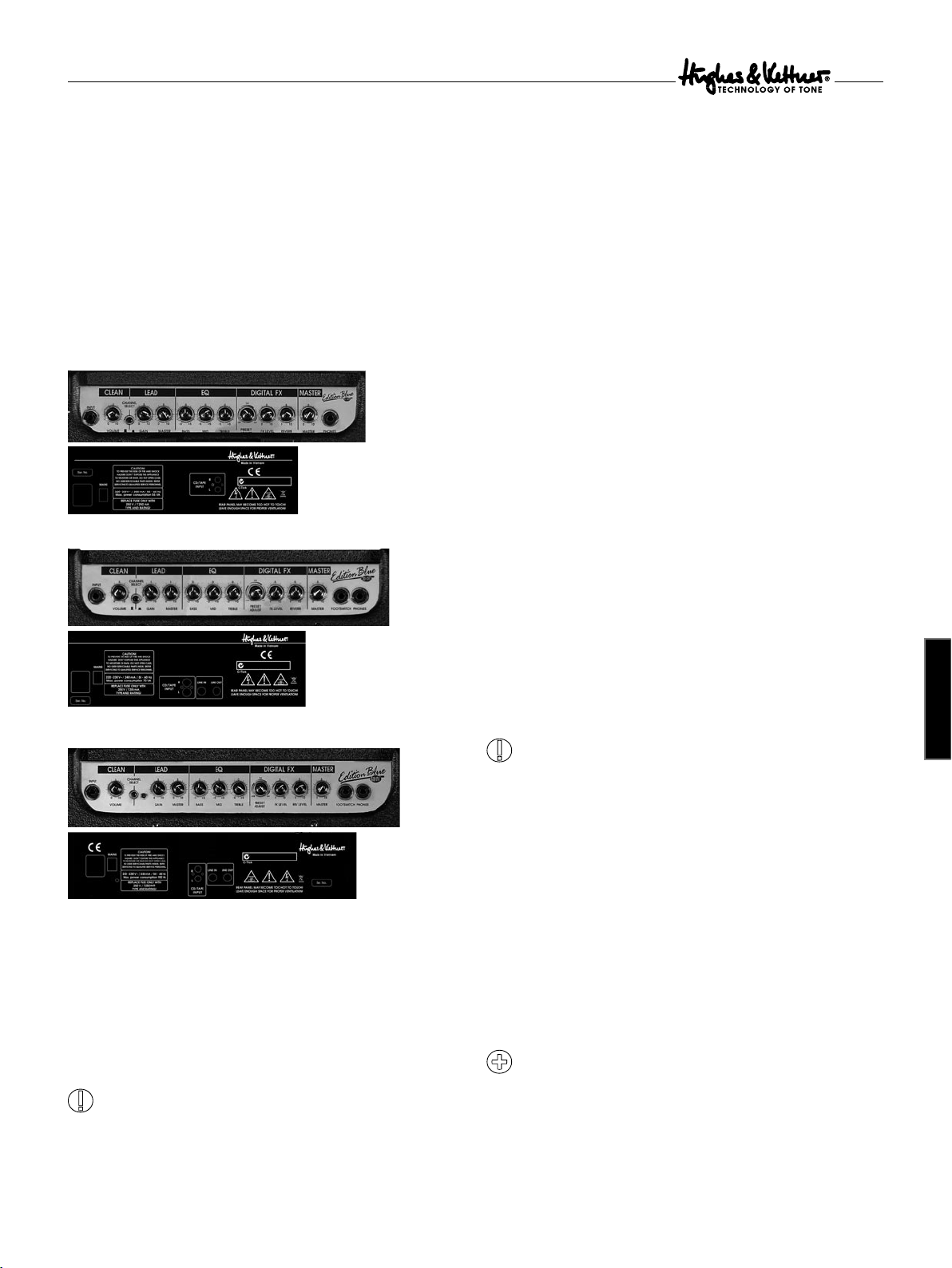
3 Outlets and other Controls
Edition Blue 15 DFX
Edition Blue 30 DFX
Edition Blue 60 DFX
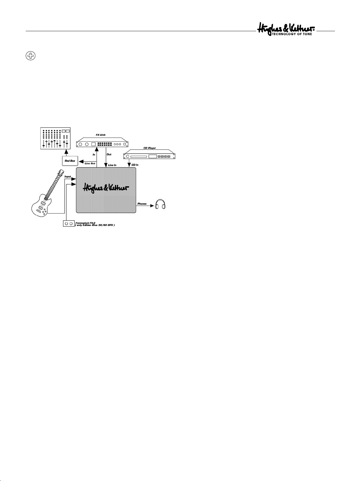
To connect a signal processor:
• Connect the processor‘s Input to the Line In jack and the
Output to the Line Out jack.
• To avoid noise, signal degradation, and interrupted signals,
only use high-quality patch cables.
• Always make sure that the signal processor is not distorting
the signal. If necessary also observe the Volume indicator of the
signal processor and use the Input and Output control of the signal
processor for dialing in a suitable Level.
• Distortion devices are not designed for use in an FX loop. Generally,
any kind of device that compresses the signal should be connected
first in the signal chain. Depending on the type of effect you want
to achieve, you may want to connect your compressor directly
between the instrument and the amp‘s Input.
• If you are using several processors or stamp boxes, ensure you
connect them in the proper order.
If you want to feed the Edition Blue™ DFX signal to a mixing console,
we recommend you route it through the Hughes & Kettner® Red
Box®. Patch the signal from the Line Out jack, as this signal path‘s
Level is here. The signal is then independent, balanced and frequency
corrected (speaker simulation) from the Master control.
3.3 Footswitch (not applicable for Edition Blue 15 DFX)
This jack is for a standard 1-way or 2-way Footswitch (e.g. Hughes
& Kettner® FS-1 or FS-2). This allows you to switch back and forth
between the Clean and Lead channels and to turn the effect section
on and off as you want. If you use a 1-way switch, the channels are
switched; if you use a 2-way switch, the channels run through switch 1
and the effects are controlled by switch 2.
If you want to be able to control the channels by the Footswitch,
the Channel Select switch must be switched to the front of the Clean
channel.
english
3.1 Input
Connecting socket for guitar
3.2 Line Out and Line In (not for Edition Blue 15 DFX)
The Edition Blue™ DFX is equipped with a serial insert. The preamp
signal of the amp is completely routed and processed through an
ingrained signal processor. The Line Out can also be used as the
Output for a mixing console.
As soon as the Line Out jack is occupied, the internal signal path
is interrupted in order to feed the external signal. If no external signal
processor is used, this jack must stay free. It cannot be used as an
additional Input.
3.4 Headphones
Headphone jack. The speaker is automatically switched of f when a
plug is inserted into this jack.
3.5 CD Input
Jack for connecting CD players, tape decks or other audio sources. The
circuit is controlled directly by the Master circuit of the Edition Blue™
DFX, which means that you can use the Master control to adjust the
Input signal‘s volume. To dial in the desired balance of levels for the
playback and guitar signals, the connected playback device has to be
equipped with some type of variable Output control.
Most audio sources have an adjustable headphone Output. You
can connect this with the CD Input with an appropriate adapter (stereo
jack/2 x cinch).
3.6 Mains
Jack for the included Mains cable. Ensure the amp‘s voltage matches your
local AC voltage rating before you plug the cord into the wall socket.
9
Page 5
Edition Blue™ 15/30/60 DFX
Before you switch on the audio playback device, turn the Master
control all the way down. Then turn up the Master control a little and
dial in the desired balance levels. Once you‘re satisfied with these
levels, gradually turn up the control to the desired overall level.
4 Standard Setup and Cable Connections
6 Troubleshooting
The Edition Blue™ DFX will not switch on:
• The amp is not receiving any Mains voltage. Check the Mains cable
to see if it is properly connected.
• The Mains fuse is defective. Replace the fuse with another suitable
fuse. If this fuse is also defective, consult your Hughes & Kettner®
dealer.
The Edition Blue™ DFX is correctly connected but the sound
is inaudible:
• One or more of the Gain and Master controls may be turned down.
• One of the internal fuses is defective. Get a qualified service
technician to replace the fuse (taking care that the values are the same)
The Clean channel cannot be activated through an external
Footswitch:
• The Channel Select switch on the front panel may not be in the „off“
position. Switch the Clean channel on.
5 Service and Maintenance
The Edition Blue™ DFX amps do not require maintenance of any
type. However, there are a few precautions to observe to significantly
lengthen the life of your amp:
• Always ensure that all peripheral devices, cords and cables are in
a state of good repair! Defective speaker cables (short circuits, loose
connections) are the most common cause of failure. Poor-quality
cables will always lead to humming problems.
• Make sure that your amp‘s ventilation ducts are not blocked
or covered.
• Avoid mechanical shocks and exposure to extreme heat, dust and
especially moisture.
• Pay close attention to the specifications of peripheral devices.
• Never connect devices with high Output signal levels (e.g. power
amps) to your amp‘s Input.
• Check for the correct voltage before you plug in the amp. If in
doubt, check with the venue‘s sound technician or the caretaker of
the building.
• Do not carry out “do it yourself” repairs. Get a qualified service
technician to replace internal fuses.
• Use a soft, damp cloth to clean the exterior surface of the
Edition Blue™ DFX.
When using the Line In / Line Out jacks, there is a humming
noise:
• An electrical or magnetic field is causing interference. Here, it is
recommended to use a DI box, e.g. Hughes & Kettner® Red Box®.
You have connected an FX processor to the Line Out jack but
the signal is totally distorted even when using Clean sounds.
• The Input of the FX processor is overloaded. Reduce the processor‘s
Input sensitivity (“Input” or “Gain”).
You have connected an FX processor to the Line Out but the
Output signal is too quiet:
• The FX processor‘s Output Level is set incorrectly. Turn the Output
Level of the processor up high.
10
Page 6
Edition Blue™ 15/30/60 DFX
7 Technical Specifications
Model: 15 DFX 30 DFX 60 DFX
Output power into 8 ohms: 15 watts 30 watts 60 watts
Max. power consumption: 55 VA 70 VA 100 VA
Mains fuse:
230/240 volt configuration T 250 mA T 315 mA T 250 mA
120 volt configuration T 500 mA T 630 mA T 500 mA
100 volt configuration T 500 mA T 630 mA T 630 mA
Internal Fuses: T 315 mA T 315 mA T 315 mA
Operational temperature range: -10˚ − +35˚ C -10˚ − +35˚ C -10˚ − +35˚ C
Weight: 7.3 kg 9.2 kg 13 kg
Measurements:
Width 404 mm 440 mm 480 mm
Height 375 mm 410 mm 490 mm
Depth 195 mm 220 mm 275 mm
Speaker: 8" Celestion 10" Jensen 12" Celestion
Super 8 Vintage Rockdriver
english
11
Page 7

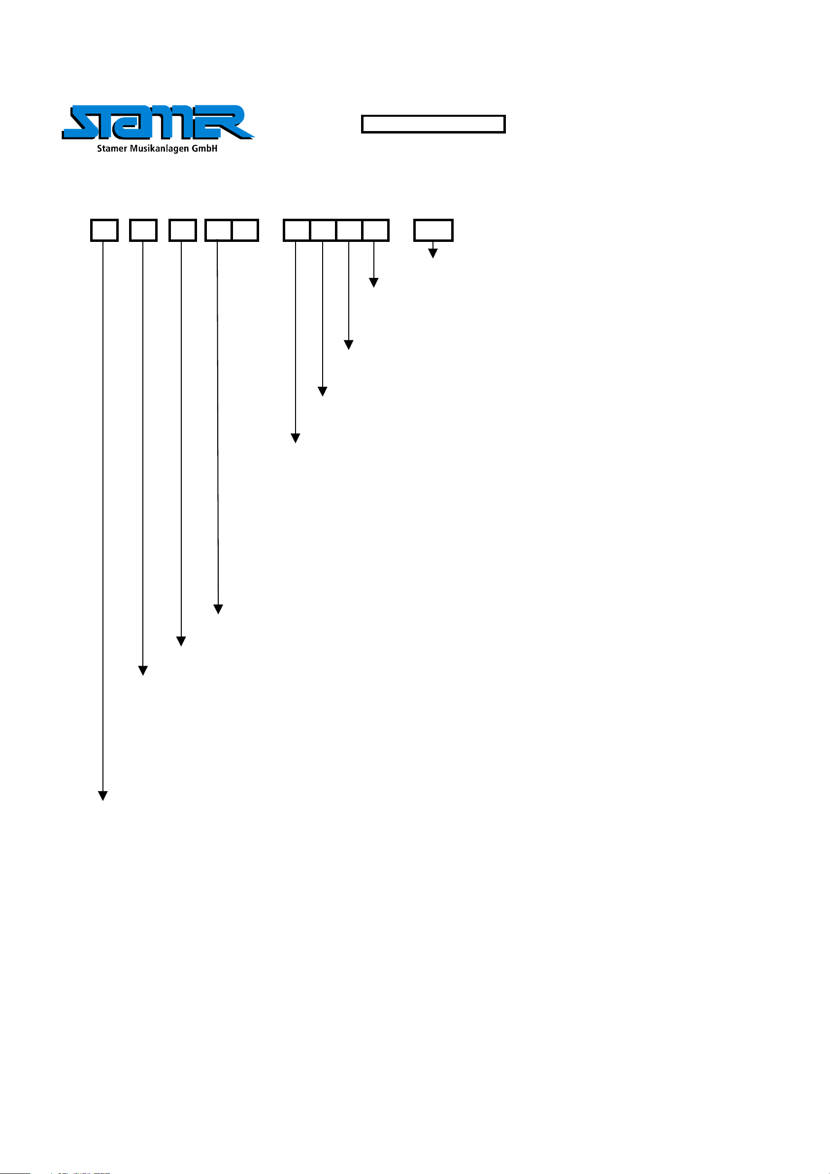
DRAWING-NUMBERS
EXAMPLE
HK0106-EX-R01-1A
VERSION
SERIAL NUMBER
DEPARTMENT:
R = R&D
REVISION
PROJECT-NR.:
HK = HK AUDIO
HU = HUGHES&KETTNER
MP = MINDPRINT
CHARACTER:
BL = SHEET METAL / BLECH
EX = EXPLODED DRAWING / EXPLOSIONSZEICHNUNG
HZ = CABINET / HOLZGEHÄUSE
KU = PLASTIC / KUNSTSTOFF
LP = PCB / LEITERPLATTEN
SO = MISCELLANEOUS / SONSTIGES
SP = SCHEMATIC / SCHALTPLÄNE
TR = TRANSFORMER / TRANSFORMATOR
GK = WIRING DIAGRAM / GERÄTEVERKABELUNG
Page 8
Stand
W
Y
r
Standard for single wire confection.
16 B 150 638 I - 485 W Z I 1015
style 1015 according UL specifications
I = completely insulated with black shrinktube or appropriate sleeve
IT = partly insulated; only crimp connection insulated.
no marking = without insulation
Z = with additional junction
no marking = without additional junction
W = angled faston
no marking = straight faston
17. Jun 04
Faston connector brass tin-plated DIN 46245
638 = 6,3 * 0,8 [mm]
488 = 4,8 * 0,8 [mm]
485 = 4,8 * 0,5 [mm] if fully insulated (I) insulation with blue shrinktube
if partly insulated (IT) use IF 602 485 .
288 = 2,8 * 0,8 [mm]
285 = 2,8 * 0,5 [mm] if fully insulated (I) insulation with blue shrinktube
if partly insulated (IT) use IF 602 485
abiso = 5mm bared and tin-plated (teilabzug)
text for special constructions, (for example. 4mm ringshaped faston)
the larger faston connector always mentioned at first. (Nathan drawing number controlling)
lenght in mm within a 50 mm raster
colour
B = black (phase conductor)
R = red
BR = brown
BL = blue (neutral conductor)
= white
G = yellow-green (ground bonding/ earthing connection)
cross section
16 = AWG 16 (prefered usage)
Q1.5 = H07VK 1,5mm² (prefered usage)
wire designation:
P + lfd Nr. = AWG single wire black, red, blue, brown or white
E + lfd Nr. = AWG single wire green- yellow
L + lfd N
FQL + lfd Nr. = crossover wiring H07VK
Regarding special wirings like wiring harness or similar, drawings will be prepared and appropriate
. = twisted AWG double wire, lenght specification always in twisted condition
drawing numbers will be stored in the article archive.
Page 9

Service Documents
Confidential, for authorized service technicians only!
Do not disclose this information to or share these documents with third parties.
TECHNICAL SERVICE:
Stamer Musikanlagen GmbH • Magdeburger Str. 8 • 66606 St.Wendel • Germany
Music & Sales P.E. GmbH • Leipziger Str. 3 • 66606 St.Wendel • Germany
HU0905
Edition Blue
60DFX
Page 10

INDEX
ÄNDERUNG
ZEICHNER
1 C90072 complete ED BLUE 60DFX wooden cabinet komplettes Holzgehäuse Edition Blue 60DFX 1
2 C90067 ED BLUE 60DFX sheet metal chassis Chassis Edition Blue 60DFX 1
3 C90025 ED BLUE H&K st rap handle Editio n Blue H&K Griff 1
4 C90025 ED BLUE H&K strap handl e Editio n Blue H&K Griff 1
5 C90025 ED BLUE H&K st rap handle Edition Blue H&K Griff 1
6 C90091 cross recessed countersunk screw, M4x30mm Senkkopfschraube 4x30mm vz 2
7 C90091 cross recessed panhead tapping screw, 4x35mm black Blechschraube 4x35mm sw 4
8 C90091 cross recessed panhead tapping screw, 4x30mm black Blechschraube 4x30mm sw 4
9 C90091 cross recessed panhead tapping screw, 4x50mm black Blechschraube 4x50mm sw 4
10 C90027 ED BLU E ruber fo ot 30/25/16mm Fuß, konisc h 30/25/16mm 4
11 C90091 panhead-Z-ABC-spax, 3,5x18mm black Spaxschraube 3,5x18mm 4
12 C90091 cross recessed panhead screw; M5x23mm Linsenkopfschraube M5x23mm 4
13 C90066 ED BLUE 60DFX speaker Edition Blue 60DFX Speaker 1
14 C90029 ED BLUE H&K logo H&K Logo 1
15 C90065 ED BLUE 60DFX acoustic baffle Edition Blue 60DFX Schallwand 1
17 C90026 ED BL UE corner Ecke 8
18 C90091 panhead-Z-A BC-spax, 3,5x13mm black Spaxschraube 3,5x13mm sw 16
19 C90025 ED BLUE H&K s trap handle Edition Blue H&K Griff 1
Item-nr.: C90012 is a screw set with all fittings used in HU0903-Edition Blue 60DFX
66606 St. Wendel / Germany
ZEICHNUNGS-NR.:
ERSTELLT VON:
GEPRÜFT/
FREIGEGEBEN VON:
WERKSTOFF:
DATEINAME:
HU0905-EX-R01-1A
Martin Drumm 1
Fehler: Keine Referenz
HU0905-EX-R01-1A-GESAMT
TITEL:
HU0905 Ex-Zeichnung
Edition Blue 60DFX
OBERFLÄCHE:
VERSION:
AM:
04.07.2006
AM:
OBERFLÄCHE
REVISION:
BLATT:
8
A1
BLÄTTER
Page 11

INDEX
ÄNDERUNG
ZEICHNER
Pos. Artikel-Nr 1 Artikel-Nr 2 Artikel-Nr 3 Description Bezeichnung Menge
1 C90064 Edition Blue 60DFX Clothing Editon Blue 60DFX Bespannstoff 1
66606 St. Wendel / Germany
ZEICHNUNGS-NR.:
ERSTELLT VON:
GEPRÜFT/
FREIGEGEBEN VON:
WERKSTOFF:
DATEINAME:
HU0905-EX-R01-1A
Martin Drumm 2
Fehler: Keine Referenz
HU0905-EX-R01-1A-GESAMT
TITEL:
HU0905 Ex-Zeichnung
Edition Blue 60DFX
OBERFLÄCHE:
VERSION:
AM:
04.07.2006
AM:
OBERFLÄCHE
REVISION:
BLATT:
8
A1
BLÄTTER
Page 12

Pos. Artikel-Nr 1 Artikel-Nr 2 Artikel-Nr 3 Description Bezeichnung Menge
1 C90146 jack nut Gegenmutter Klinkenbuchse 5
2 C90 107 ED BL UE poti- knob P otiknopf 8
3 C90147 volume nut Poti Mutter M7 8
4 C90148 volume washer Kunststoffring Poti 8
5 C90068 ED BLUE 60DFX plexiglas Plexiglas 1
7 C90067 ED BLUE 60DFX sheet metal chassis Chassis Edition Blue 1
9 C90035 sheet metal nut, 3,9mm brass Blechmuttern 3,9mm ms 8
10 C90037 power inlet Net zbuchse 1
11 C90041 ED BLUE LED board LED Platine 2
12 C90091 cross recessed panhead screw, M3x8mm Linsenschraube M3x8mm vz 4
13 C90091 cross recessed panhead screw, M4x10mm black Linsenschraube M4x10mm sw 4
14 C90091 nut M4 M4 Mutter 5
15 C90070 (230V) C90101 (117V) C90100 (100V) ED BLUE 60DFX mains transformer Transformator 1
16 C90145 jack washer Kunstst offring Klinkenbuchse 5
17 C90069 ED BLUE 60DFX pre amp board Vorstufe Edition Blue 60DFX 1
18 C90091 cross recessed panhead screw; 3x8mm black Blechschraube 3x8mm sw 4
19 C90091 to oth washe r Fächers cheibe 2
20 C900 23 PUSH SWITCH T ast-Schalt er 1
21 C90 154 input/o utput board B uchsenplatine 1
22 C90091 cross rece ssed panhead screw; 3x8mm black Blechschraube 3x8mm sw 2
25 C90120 heat sink (black anodize) 50x28x40mm (2hole) Kühlkörper, sw 50x28x40mm 1
26 C9 0150 wa sher d=12mm Kunst stoffring d=12mm 2
27 C90106 mainsswitch ED BLUE DFX Netzschalter ED Blue DFX 1
28 C90091 cross recessed panhead screw; 3x6mm black Blechschraube 3x6mm sw 2
29 C90155 PCB-Distance Holder 11mm Distanzhalter 11mm 1
30 C90061 ED BLUE DFX board DFX Plat ine 1
31 C90135 he at sink al ext rution 15x25x11mm Kühlk örpe r, 15x25x11mm 2
39
37
38
INDEX
ÄNDERUNG
ZEICHNER
36
35
34
33
32
19
25
Pos. Artikel-Nr 1 Artikel-Nr 2 Artikel-Nr 3 Description Bezeichnung Menge
32 C90091 cross recessed panhead screw; 3x8mm black Ble chschraube 3x8mm sw 2
33 C90119 heat sink (black anod ize) 50 x28x40mm Kühlkörper, sw 50x28x40mm 1
34 C90091 spring washer Federring d=3mm 1
35 C90152 insulated bushing d=3mm Isolationsring d =3mm 2
36 C90153 insulat ed spacer TD220, Mica Isola tionsscheibe 2
37 C90121 fuse case Sicherungseinsatz 1
38 932021 fuse T250mA L250V Feinsicherung T250mA L250V 1
39 932024 fus e T315mA L250V Fe insicherung T315mA L250V 1
Item-nr.: C90012 is a screw set with all fittings used in HU0903-Edition Blue 60DFX
66606 St. Wendel / Germany
ZEICHNUNGS-NR.:
ERSTELLT VON:
GEPRÜFT/
FREIGEGEBEN VON:
WERKSTOFF:
DATEINAME:
HU0905-EX-R01-1A
Martin Drumm 3
Fehler: Keine Referenz
HU0905-EX-R01-1A-GESAMT
TITEL:
HU0905 Ex-Zeichnung
Edition Blue 60DFX
OBERFLÄCHE:
VERSION:
AM:
04.07.2006
AM:
OBERFLÄCHE
REVISION:
BLATT:
8
A1
BLÄTTER
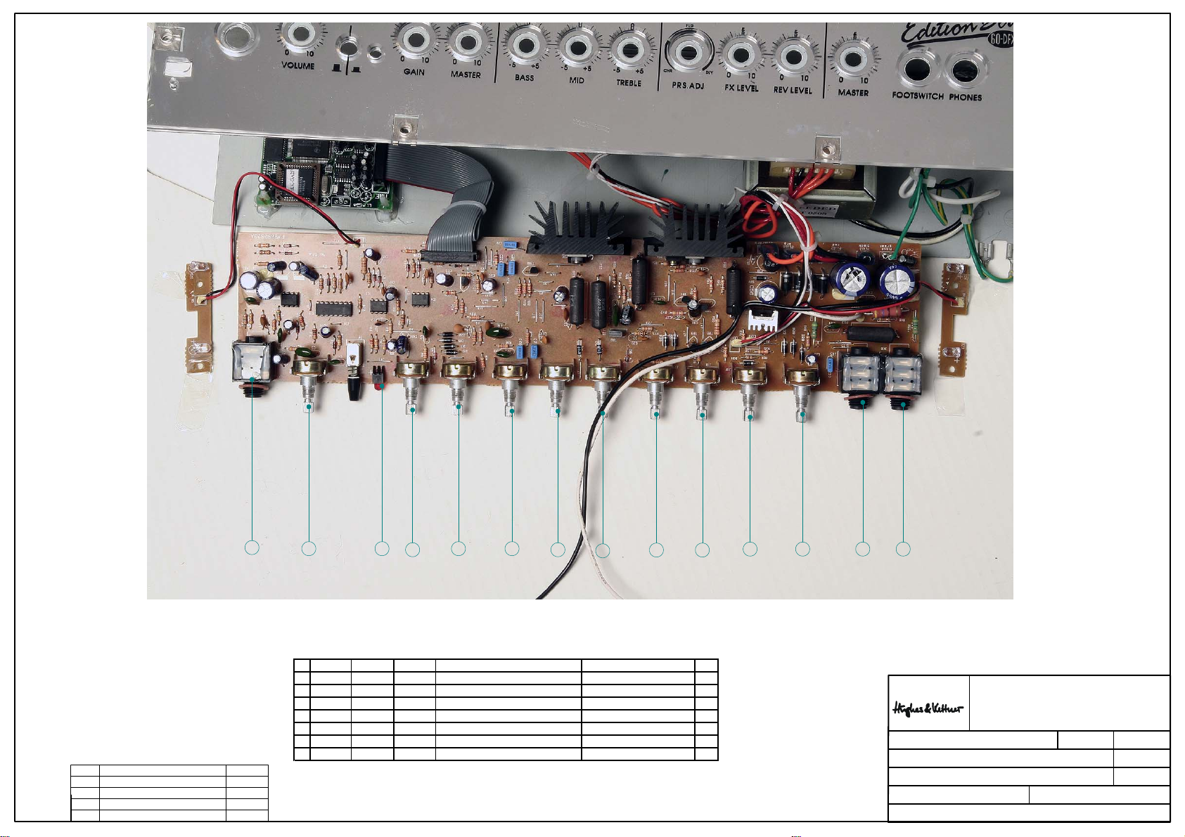
Page 13
INDEX
ÄNDERUNG
2
ZEICHNER
5
Pos. Artike l-Nr 1 Artike l-Nr 2 Artikel- Nr 3 D escription Bez eichnung Me nge
1 C90014 LED 5mm, color red LED 5mm, Farbe rot 1
2 C90015 MONO JACK (JK1,JK3,JK4) Mono Kl. Buchse 3
3 C90016 STEREO JACK (JK5,JK13) Stereo Kl.Buchse 2
4 C90017 POTENTIOMETER RV160-20 15SP B50K (P6) Poti RV160-20 15SP B50K (P6) 1
5 C90019 POTENTIOMETER RV160-20 15SP A10K (P1) Poti RV160-20 15SP A10K (P1) 1
6 C90020 POTENTIOMETER RV160-20 15SP B10K (P3, P10) Poti RV160-20 15SP B10K (P3, P10) 2
7 C90021 POTENTIOMETER RV160-20 15SP A50K (P2, P4, P7) Poti RV160-20 15SP A50K (P2, P4, P7) 3
1
7
6 7
8
4
8 8
6
3 37
TITEL:
HU0905 Ex-Zeichnung
66606 St. Wendel / Germany
ZEICHNUNGS-NR.:
ERSTELLT VON:
GEPRÜFT/
FREIGEGEBEN VON:
WERKSTOFF:
DATEINAME:
HU0905-EX-R01-1A
Martin Drumm 4
Fehler: Keine Referenz
HU0905-EX-R01-1A-GESAMT
Edition Blue 60DFX
OBERFLÄCHE:
VERSION:
AM:
04.07.2006
AM:
OBERFLÄCHE
REVISION:
BLATT:
8
A1
BLÄTTER
Page 14

13 13
13
14
14 14 14 10
20
13
12
6 6
1
1313
1
34
18
2
2020
5
1
12 12 12 12
7
11
9
16
9
1617
19
9
8
1515
19
21
11 11
INDEX
ÄNDERUNG
ZEICHNER
Pos. Artikel-Nr 1 Artikel-Nr 2 Artikel-Nr 3 Description Bezeichnung Menge
1 938009 NPN transistor BC 546B (TR1, TR2, TR10) NPN Transistor BC 546B 9
2 938022 PNP transistor BD 238 (TR3) PNP Transistor BD 238 1
3 C90108 NPN t ransistor BD 679A or DB 681 (molding type) (TR4) NPN Transistor BD 679A od er DB 681(formgepresst) 1
4 938034 NPN transistor BDX 53C (or Tip132) (TR5) NPN Transistor BDX 53C oder Tip132 1
5 938035 PNP transistor BDX 54C (or Tip137) (TR6) PNP Transistor BDX 54C oder Tip137 1
6 938006 PNP transistor BC556B (TR8, TR9) PNP Transistor BC556B 2
7 938028 FET BF245B (TR7) FET BF245B 1
8 C90 109 swit ching IC HCF405 3BEY (IC3) Schalt IC HCF40 53B EY 1
9 C90 129 d ual o f amp IC TL 072CP (IC1, IC2, IC4) IC TL072CP 3
10 C90136 REG IC KA7805 (REG1) IC KA7805 1
11 C90112 silico n switching dio de 1N4148, T (D1, D2, D5) Silliziumd iode 1N4148, T (D1, D2, D5) 3
12 C90130 silicon rectifier diode 1N4004, T (D17, D18, D19, Silliziumgleichrichterdiode 1N4004, T 5
D20, D27)
13 C90131 silicon rectifier diode 1N4007, T (D21, D22, D28, Silliziumgleichrichterdiode 1N4007, T 6
D29, D30, D31)
14 C90114 silicon rectifier diode 1N5402, T (D7, D8, D9, D10) Silliziumgle ichrichterdiode 1N5402, T 4
15 C90115 zener diode 1N5228B(3,9V/0,5W),T (D3, D4) Zenerdiode 1N5228B(3,9V/0,5W),T 2
16 C90133 zener diode 1N5223B (2,7V/0,5W), T (D32, D33) Zenerdiode 1N5223B (2,7V/0,5W), T 2
17 C90134 zene r diode 1N5231B (5 ,1V/0,5W), T (D35 ) Zenerdiod e 1N5223B (2,7V/0,5W), T 2
18 C90116 zener diode 1N5235B (6,8V/0,5W), T (D6, D16) Zenerdiode 1N5235B (6,8V/0,5 W), T 2
19 C90117 zener diode 1N5236B (7,5V /0,5W) T (D 14, D15) Zenerdio de 1N5236B (7,5V/0,5 W) T 2
20 C90118 zener diode ZPY15 (15V/1,3W) (D11, D12) Zenerdiode ZPY15 (15V/1,3W) 2
21 C90132 bridge diode 2W04M (BR1) Diodenbrücke 2W04M 1
66606 St. Wendel / Germany
ZEICHNUNGS-NR.:
ERSTELLT VON:
GEPRÜFT/
FREIGEGEBEN VON:
WERKSTOFF:
DATEINAME:
HU0905-EX-R01-1A
Martin Drumm 5
Fehler: Keine Referenz
HU0905-EX-R01-1A-GESAMT
TITEL:
HU0905 Ex-Zeichnung
Edition Blue 60DFX
OBERFLÄCHE:
VERSION:
AM:
04.07.2006
AM:
OBERFLÄCHE
REVISION:
BLATT:
8
A1
BLÄTTER
Page 15

INDEX
ÄNDERUNG
ZEICHNER
Pos. Artike l-Nr 1 Artike l-Nr 2 Artikel- Nr 3 De scription Bezeichnung Menge
1 C90138 CON5: FLAT WIRE UL1007 AWG26 L=200m/m Litze sw 1
2 C90139 CON4: FLAT WIRE UL1007 AWG26 L=200m/m Litze rot 1
3 C90161 CON1: 3P HOUSING FLAT WIRE UL1007 AWG26: W1 Litze sw/w/w 1
4 C90142 PLUG5(+):205/TER WIRE UL1015 AWG22 WHT 400m/m Litze weiß 1
5 C90143 PLUG6(-):205/TER WIRE UL1015 AWG22 BL 400m/m Litze sw 1
6 C90164 PLUG4: 250/TER WIRE UL1015 AWG18 210m/m GRN Litze grün/gelb 1
7 C90165 LEAD WIRE UL1015 AWG18 YEL-GRN L=210m/m Litze grün/gelb 1
8 C90166 (250/205 SLEEVE) LEAD WIRE UL1617 AWG22 WHITE Litze weiß 1
66606 St. Wendel / Germany
ZEICHNUNGS-NR.:
ERSTELLT VON:
GEPRÜFT/
FREIGEGEBEN VON:
WERKSTOFF:
DATEINAME:
HU0905-EX-R01-1A
Martin Drumm 6
Fehler: Keine Referenz
HU0905-EX-R01-1A-GESAMT
TITEL:
HU0905 Ex-Zeichnung
Edition Blue 60DFX
OBERFLÄCHE:
VERSION:
AM:
04.07.2006
AM:
OBERFLÄCHE
REVISION:
BLATT:
8
A1
BLÄTTER
Page 16

INDEX
ÄNDERUNG
ZEICHNER
Pos. Artikel-Nr 1 Artikel-Nr 2 Artikel-Nr 3 Description Bezeichnung Menge
1 C90 167 WIR E UL10 15 A WG22 310m/ m L itze ora nge 1
2 C90168 RING/TER WIRE UL1007 AWG18 GREEN Litze grün 1
66606 St. Wendel / Germany
ZEICHNUNGS-NR.:
ERSTELLT VON:
GEPRÜFT/
FREIGEGEBEN VON:
WERKSTOFF:
DATEINAME:
HU0905-EX-R01-1A
Martin Drumm 7
Fehler: Keine Referenz
HU0905-EX-R01-1A-GESAMT
TITEL:
HU0905 Ex-Zeichnung
Edition Blue 60DFX
OBERFLÄCHE:
VERSION:
AM:
04.07.2006
AM:
OBERFLÄCHE
REVISION:
BLATT:
8
A1
BLÄTTER
Page 17

INDEX
ÄNDERUNG
ZEICHNER
66606 St. Wendel / Germany
ZEICHNUNGS-NR.:
ERSTELLT VON:
GEPRÜFT/
FREIGEGEBEN VON:
WERKSTOFF:
DATEINAME:
HU0905-EX-R01-1A
Martin Drumm 8
Fehler: Keine Referenz
HU0905-EX-R01-1A-GESAMT
TITEL:
HU0905 Ex-Zeichnung
Edition Blue 60DFX
OBERFLÄCHE:
VERSION:
AM:
04.07.2006
AM:
OBERFLÄCHE
REVISION:
BLATT:
8
A1
BLÄTTER
Page 18

HU0905-EX-R01-1A-COMPLETE (PAGE 1, 2)
part-no. 1 (230V) part-no. 2 (117V) part-no. 3 (100V) Description Bezeichnung Quantity
C90025 ED BLUE H&K strap handle Edition Blue H&K Griff 1
C90026 ED BLUE corner Ecke 8
C90027 ED BLUE ruber foot 30/25/16mm Fuß, konisch 30/25/16mm 4
C90029 ED BLUE H&K logo H&K Logo 1
C90064 Edition Blue 60DFX Clothing Editon Blue 60DFX Bespannstoff 1
C90065 ED BLUE 60DFX acoustic baffle Edition Blue 60DFX Schallwand 1
C90066 ED BLUE 60DFX speaker Edition Blue 60DFX Speaker 1
C90067 ED BLUE 60DFX sheet metal chassis Chassis Edition Blue 60DFX 1
C90072 complete ED BLUE 60DFX wooden cabinet komplettes Holzgehäuse Edition Blue 60DFX 1
HU0905-EX-R01-1A-CHASSIS (PAGE 3)
part-no. 1 (230V) part-no. 2 (117V) part-no. 3 (100V) Description Bezeichnung Quantity
932021 fuse T250mA L250V Feinsicherung T250mA L250V 1
932024 fuse T315mA L250V Feinsicherung T315mA L250V 1
C90023 PUSH SWITCH Tast-Schalter 1
C90035 sheet metal nut, 3,9mm brass Blechmuttern 3,9mm ms 8
C90037 powerinlet Netzbuchse 1
C90041 ED BLUE LED board LED Platine 2
C90061 ED BLUE DFX board DFX Platine 1
C90067 ED BLUE 60DFX sheet metal chassis Chassis Edition Blue 1
C90068 ED BLUE 60DFX plexiglas Plexiglas 1
C90069 ED BLUE 60DFX preamp board Vorstufe Edition Blue 60DFX 1
C90070 C90101 C90100 ED BLUE 60DFX mains transformer Transformator 1
C90106 mainsswitch ED BLUE DFX Netzschalter ED Blue DFX 1
C90107 ED BLUE poti-knob Potiknopf 8
C90119 heat sink (black anodize) 50x28x40mm Kühlkörper, sw 50x28x40mm 1
C90120 heat sink (black anodize) 50x28x40mm (2hole) Kühlkörper, sw 50x28x40mm 1
C90121 fuse case Sicherungseinsatz 1
C90135 heat sink al extrution 15x25x11mm Kühlkörper, 15x25x11mm 2
C90145 jack washer Kunststoffring Klinkenbuchse 5
C90146 jack nut Gegenmutter Klinkenbuchse 5
C90147 volume nut Poti Mutter M7 8
C90148 volume washer Kunststoffring Poti 8
C90150 washer d=12mm Kunststoffring d=12mm 2
C90152 insulated bushing d=3mm Isolationsring d=3mm 2
C90153 insulated spacer TD220, Mica Isolationsscheibe 2
C90154 input/output board Buchsenplatine 1
C90155 PCB-Distance Holder 11mm Distanzhalter 11mm 1
HU0905-EX-R01-1A-ELECTRONICS (PAGE 4, 5)
part-no. 1 (230V) part-no. 2 (117V) Ref.Destricption Description Bezeichnung Quantity
938006 TR8, TR9 PNP transistor BC556B PNP Transistor BC556B 2
938009 TR1, TR2, TR10 NPN transistor BC 546B NPN Transistor BC 546B 9
938022 TR3 PNP transistor BD 238 PNP Transistor BD 238 1
938028 TR7 FET BF245B FET BF245B 1
938034 TR5 NPN transistor BDX 53C (or Tip132) NPN Transistor BDX 53C oder Tip132 1
938035 TR6 PNP transistor BDX 54C (or Tip137) PNP Transistor BDX 54C oder Tip137 1
C90014 JK1,JK3,JK4 LED 5mm, color red LED 5mm, Farbe rot 1
C90015 MONO JACK Mono Kl. Buchse 3
C90016 JK5,JK13 STEREO JACK Stereo Kl.Buchse 2
C90017 P6 POTENTIOMETER RV160-20 15SP B50K Poti RV160-20 15SP B50K (P6) 1
Page 19
C90018 P5, P8, P9 POTENTIOMETER RV160-20 15SP B5K Poti RV160-20 15SP B5K (P5, P8, P9) 3
C90019 P1 POTENTIOMETER RV160-20 15SP A10K Poti RV160-20 15SP A10K (P1) 1
C90020 P3, P10 POTENTIOMETER RV160-20 15SP B10K Poti RV160-20 15SP B10K (P3, P10) 2
C90021 P2, P4, P7 POTENTIOMETER RV160-20 15SP A50K Poti RV160-20 15SP A50K (P2, P4, P7) 3
C90108 TR4 NPN transistor BD 679A or DB 681 (molding type) NPN Transistor BD 679A oder DB 681(formgepresst) 1
C90109 IC3 switching IC HCF4053BEY Schalt IC HCF4053BEY 1
C90112 D1, D2, D5 silicon switching diode 1N4148, T Silliziumdiode 1N4148, T (D1, D2, D5) 3
C90114 D7, D8, D9, D10 silicon rectifier diode 1N5402, T Silliziumgleichrichterdiode 1N5402, T 4
C90115
C90116 D6, D16 zener diode 1N5235B (6,8V/0,5W), T Zenerdiode 1N5235B (6,8V/0,5W), T 2
C90117 D14, D15 zener diode 1N5236B (7,5V/0,5W) T Zenerdiode 1N5236B (7,5V/0,5W) T 2
C90118 D11, D12 zener diode ZPY15 (15V/1,3W) Zenerdiode ZPY15 (15V/1,3W) 2
C90129 IC1, IC2, IC4 dual of amp IC TL072CP IC TL072CP 3
C90130
C90131 D21, D22, D28, D29, D30, D31 silicon rectifier diode 1N4007, T Silliziumgleichrichterdiode 1N4007, T 6
C90132 BR1 bridge diode 2W04M Diodenbrücke 2W04M 1
C90133 D32, D33 zener diode 1N5223B (2,7V/0,5W), T Zenerdiode 1N5223B (2,7V/0,5W), T 2
C90134 D35 zener diode 1N5231B (5,1V/0,5W), T Zenerdiode 1N5223B (2,7V/0,5W), T 2
C90136 REG1 REG IC KA7805 IC KA7805 1
HU0905-EX-R01-1A-CABLING (PAGE 6, 7, 8)
part-no. 1 (230V) part-no. 2 (117V) part-no. 3 (100V) Description Bezeichnung Quantity
C90138 CON5: FLAT WIRE UL1007 AWG26 L=200m/m Litze sw 1
C90139 CON4: FLAT WIRE UL1007 AWG26 L=200m/m Litze rot 1
C90142 PLUG5(+):205/TER WIRE UL1015 AWG22 WHT 400m/m Litze weiß 1
C90143 PLUG6(-):205/TER WIRE UL1015 AWG22 BL 400m/m Litze sw 1
C90161 CON1: 3P HOUSING FLAT WIRE UL1007 AWG26: W1 Litze sw/w/w 1
C90164 PLUG4: 250/TER WIRE UL1015 AWG18 210m/m GRN Litze grün/gelb 1
C90165 LEAD WIRE UL1015 AWG18 YEL-GRN L=210m/m Litze grün/gelb 1
C90166 (250/205SLEEVE) LEAD WIRE UL1617 AWG22 WHITE Litze weiß 1
C90167 WIRE UL1015 AWG22 310m/m Litze orange 1
C90168 RING/TER WIRE UL1007 AWG18 GREEN Litze grün 1
D3, D4
D17, D18, D19, D20, D27
zener diode 1N5228B(3,9V/0,5W),T Zenerdiode 1N5228B(3,9V/0,5W),T 2
silicon rectifier diode 1N4004, T Silliziumgleichrichterdiode 1N4004, T 5
HU0905-EDITION BLUE 60DFX SCREW SET
part-no. 1 (230V) part-no. 2 (117V) part-no. 3 (100V) Description Bezeichnung Quantity
C90091 cross recessed countersunk screw, M4x30mm Senkkopfschraube 4x30mm vz 2
C90091 cross recessed panhead screw, M3x8mm Linsenschraube M3x8mm vz 4
C90091 cross recessed panhead screw, M4x10mm black Linsenschraube M4x10mm sw 4
C90091 cross recessed panhead screw; 3x6mm black Blechschraube 3x6mm sw 2
C90091 cross recessed panhead screw; 3x8mm black Blechschraube 3x8mm sw 6
C90091 cross recessed panhead screw; 3x8mm black Blechschraube 3x8mm sw 2
C90091 cross recessed panhead screw; M5x23mm Linsenkopfschraube M5x23mm 4
C90091 cross recessed panhead tapping screw, 4x30mm black Blechschraube 4x30mm sw 4
C90091 cross recessed panhead tapping screw, 4x35mm black Blechschraube 4x35mm sw 4
C90091 cross recessed panhead tapping screw, 4x50mm black Blechschraube 4x50mm sw 4
C90091 nut M4 M4 Mutter 5
C90091 panhead-Z-ABC-spax, 3,5x13mm black Spaxschraube 3,5x13mm sw 16
C90091 panhead-Z-ABC-spax, 3,5x18mm black Spaxschraube 3,5x18mm 4
C90091 spring washer Federring d=3mm 1
C90091 tooth washer Fächerscheibe 2
Page 20

INDEX CHANGES
RESP.
66606 St. Wendel / Germany
DRAWING-NO.:
DRAWN BY:
CHECKED BY:
MATERIAL:
FILENAME:
Martin Drumm 1
Fehler: Keine Referenz
Schematic_ED60DFX
TITLE:
HU0905-Schaltplan
Edition Blue 60DFX
FINISH:
VERSION:
DATE:
20.07.2006
DATE:
OBERFLÄCHE
REVISION:
PAGE:
1
A1
PAGES
 Loading...