

HK HK Audio Repair Instruction

Service and
Repair Instruction
for the
HK Audio
Power Amplifier
Projector
Bass
1

1) Terms and Definitions:
- IN: Test Signal Input
- MP: Measuring Points for signal measurements
- R: Resistor to adjust quiescent current
Important: The unit must have an operational fan during testing.
2
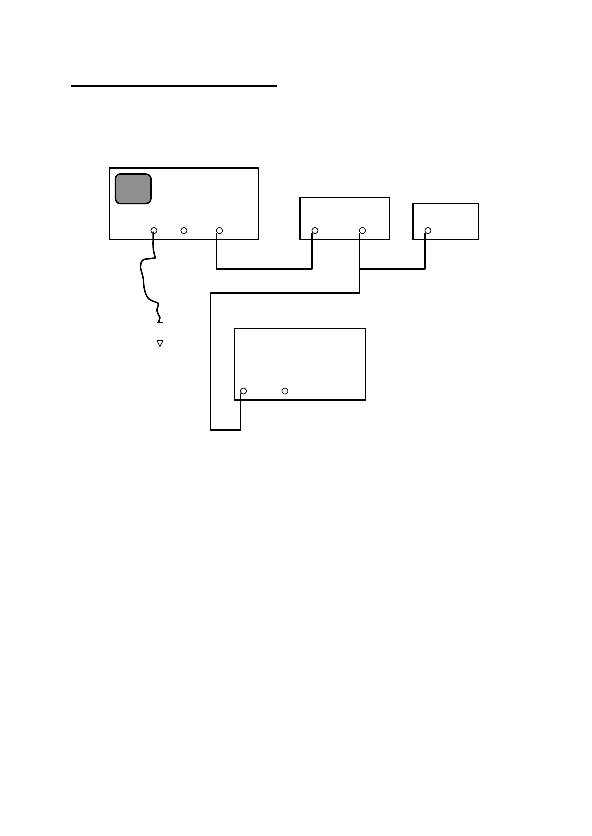
2) Basic Measurement Set-up:
Oscilloscope
Function Generator
Input
Input
Ch I
Ch II Trig.Ext.
Amplifier
Probe
Input
Through
Input Impedance at the scope: 10 MO
Trig.
Outp.
50O
Outp.
Voltmeter
In
NOTE. Turn the input gain controls fully clockwise (viewed from the
rear panel)
3
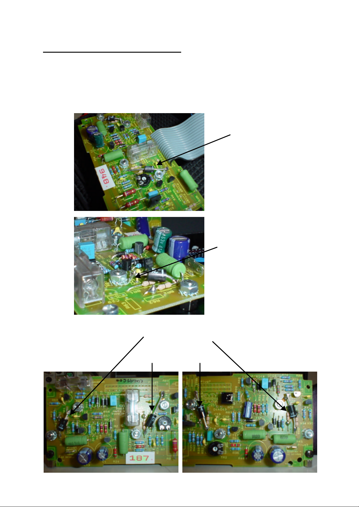
3) Over voltage Protecting Diode:
RRM
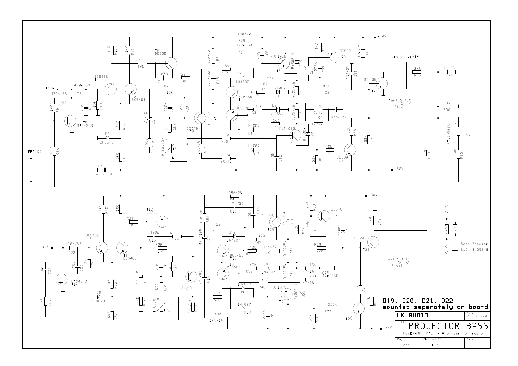
Four additional diodes must be mounted seperately on amplifier board to protect the
darlington transistors MJ11015 and MJ11016 against over voltage (induced voltage
from speaker).
Type of diode: BY 500 – 400 or similar
See the following pictures for fitting details.
Protecting Diode
BY 500 - 400
Nominal Current: 5 A
Repetitive peak
reverse voltage
V
: 400 V
T2 (MJ11015) T24
T3 (MJ11016) T25
mounted with soldering lug
4

4) Quiescent Current adjustment:
After replacement of any components, it is vital the output stage quiescent
current is adjusted.
A range from 15 to 20 mA is tolerable.
To adjust the quiescent current, measure the voltage over the both 0,22O / 5W
resistors for the relevant channel. A voltage of 6,6 mV to 8,8 mV corresponds
to the correct current range.
Step 1
Measure the voltage over resistors R4 and R14. Adjust the voltage with trim
pot TR1.
Step 2
Measure the voltage over resistors R44 and R45. Adjust the voltage with trim
pot TR2.
5
5) Results at the Measurement:
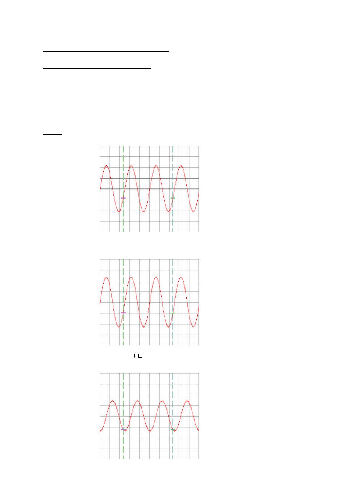
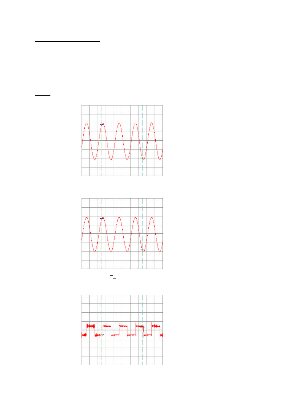
Pre-amplifier Functional Check:
Apply the signal to Input 3; Pins 1 and 2 shorted together
Scope to MP1
Note.
In step 2, the input amplitude is increased to ensure that the input stage does
not clip. In step 3, the input is changed from a sinusoid to a square wave to
check the input filters are working correctly.
MP 1: Input Signal: sin; 80 Hz; 1 V
Scope: 5 ms /div; 500 mV= /div
Input Signal: sin; 80 Hz; 5V
Scope: 5 ms /div; 2V= /div
RMS
RMS
Input Signal: ; 80 Hz; 0,7 V
RMS
Scope: 5 ms /div; 500 mV= /div
6

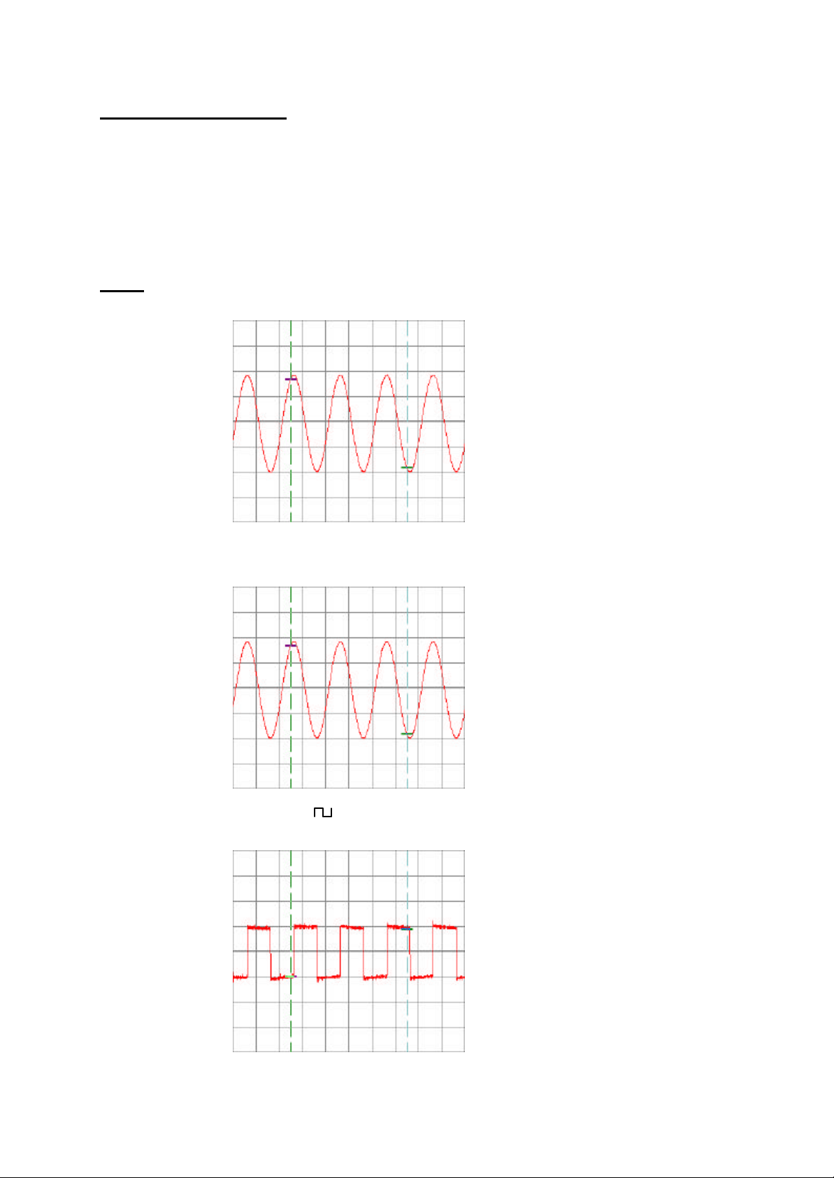
Pre-amplifier Functional Check:
Apply the signal to Input 2; Pins 1 and 3 shorted together
Scope to MP1
Note.
In step 2, the input amplitude is increased to ensure that the input stage
does not clip. In step 3, the input is changed from a sinusoid to a square
wave to check the input filters are working correctly.
MP 1: Input Signal: sin; 80 Hz; 1 V
Scope: 5 ms /div; 500 mV= /div
Input Signal: sin; 80 Hz; 5V
Scope: 5 ms /div; 2V= /div
RMS
RMS
Input Signal: ; 80 Hz; 0,7 V
RMS
Scope: 5 ms /div; 500 mV= /div
7

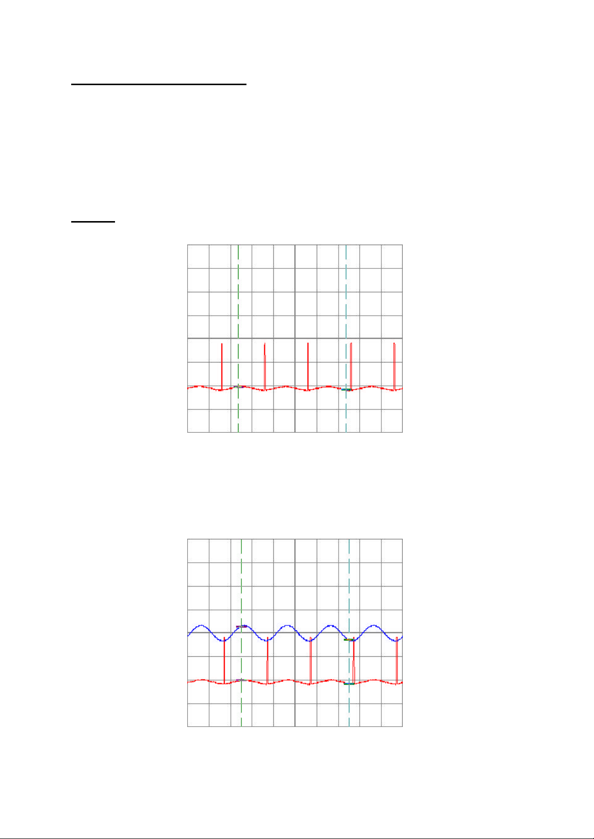
Poweramp Limiter Driver:
MP2:
Look at MP3 (Page 9)
and MP 6 (Page 12)
8
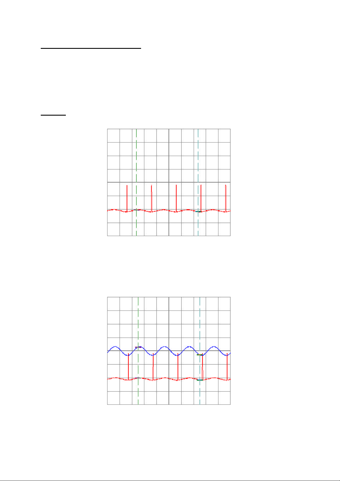
Power-amplifier Limiter Check:
Apply the signal to the junction of R72 and C31, Scope to MP2, MP3, see the
attached diagram.
Note.
The GAIN must be turned fully clockwise, and should be reset each time a
measurement is taken
MP 2, 3: Signal Input: sin; 1 kHz; 1,13 V
Scope: 500 µs /div; 1V= /div
Explanation to the following picture:
In picture 2 the input sinusoid is shown on channel 2, whilst the output signal is
on channel 1. The pulses must occur only at the most negative point on the
output waveform.
RMS
9
Power-amplifier Check: Dummy load: 8O + to Plug1; - to Ground
Apply input signal directly to the power amplifier, between R72 and C31, see
the attached diagram.
Note.
In step 2, the input amplitude is increased to ensure that the input stage does
not clip. In step 3, the input is changed from a sinusoid to a square wave to
check the frequency response of the amplifier.
MP 4: Input Signal: sin; 1 kHz; 0,5V
RMS
Scope: 500 µs /div; 10V= /div
Input Signal: sin; 1 kHz; 0,95V
RMS
Scope: 500 µs /div; 20V= /div
Input Signal: ; 1 kHz; 0,01V
RMS
Scope: 500 µs /div; 500 mV= /div
Attention: Do not run the amplifier for more than 5 seconds whilst making these
tests.
10

Power-amplifier Check: Dummy load: 8O + to Plug3; - to Ground
Apply input signal directly to the power amplifier, between R72 and C31, see
the attached diagram.
Note.
In step 2, the input amplitude is increased to ensure that the input stage does
not clip. In step 3, the input is changed from a sinusoid to a square wave to
check the frequency response of the amplifier.
MP 5: Input Signal: sin; 1 kHz; 0,5V
RMS
Scope: 500 µs /div; 10V= /div
Input Signal: sin; 1 kHz; 0,95V
RMS
Scope: 500 µs /div; 20V= /div
Input Signal: ; 1 kHz; 0,01V
RMS
Scope: 500 µs /div; 500 mV= /div
Attention: Do not run the amplifier for more than 5 seconds whilst making these
tests.
11
Power-amplifier Limiter Check:
Apply the signal to the junction of R72 and C31, Scope to MP2, MP6, see the
attached diagram.
Note.
The GAIN must be turned fully clockwise, and should be reset each time a
measurement is taken
MP 2, 6: Signal Input: sin; 1 kHz; 1,13 V
Scope: 500 µs /div; 1V= /div
Explanation to the following picture:
In picture 2 the input sinusoid is shown on channel 2, whilst the output signal is
on channel 1. The pulses must occur only at the most negative point on the
output waveform.
RMS
12
Power-amplifier Check: Dummy load: 8O + to Plug1; - to Ground
Apply input signal directly to the power amplifier, between R72 and C31, see
the attached diagram.
Note.
In step 2, the input amplitude is increased to ensure that the input stage does
not clip. In step 3, the input is changed from a sinusoid to a square wave to
check the frequency response of the amplifier.
MP 7: Input Signal: sin; 1 kHz; 0,5V
Scope: 500 µs /div; 10V= /div
Input Signal: sin; 1 kHz; 1V
RMS
Scope: 500 µs /div; 20V= /div
RMS
Input Signal: ; 1 kHz; 0,01V
RMS
Scope: 500 µs /div; 500 mV= /div
Attention: Do not run the amplifier for more than 5 seconds whilst making these
tests.
13

Power-amplifier Check: Dummy load: 8O + to Plug3; - to Ground
Apply input signal directly to the power amplifier, between R72 and C31, see
the attached diagram.
Note.
In step 2, the input amplitude is increased to ensure that the input stage does
not clip. In step 3, the input is changed from a sinusoid to a square wave to
check the frequency response of the amplifier.
MP 8: Input Signal: sin; 1 kHz; 0,5V
Scope: 500 µs /div; 10V= /div
Input Signal: sin; 1 kHz; 1V
RMS
Scope: 500 µs /div; 20V= /div
RMS
Input Signal: ; 1 kHz; 0,01V
RMS
Scope: 500 µs /div; 500 mV= /div
Attention: Do not run the amplifier for more than 5 seconds whilst making these
tests.
14
IN
IN
+15 Vdc
-15 Vdc
MP2
MP1
24 Vdc
-26 Vdc
47 Vdc
-47 Vdc
IN
IN
6,8 Vdc
-1,1 Vdc
-27 Vdc
6,8 Vdc
-1,1 Vdc
1,1 Vdc
R4
R14
R44
R45
MP3
MP5
MP4
1,1 Vdc
35 Vac
-26 Vdc
15 Vdc
-15 Vdc
-27 Vdc
IN+
 Loading...