

Page 1

Service Documents
Confidential, for authorized service technicians only!
Do not disclose this information to or share these documents
with third parties.
Vertraulich! Nur für autorisierte Servicetechniker!
Nicht zur Weitergabe an Dritte freigegeben!
TECHNICAL SERVICE:
Stamer Musikanlagen GmbH • Magdeburger Str. 8 • 66606 St.Wendel • Germany
Music & Sales P.E. GmbH • Leipziger Str. 3 • 66606 St.Wendel • Germany
Note!
The components used in this product - particularly parts affecting
safety as well as speakers and transformers - were developed and
manufactured to certain specifications. Please use original spare
parts only to ensure the product remains fully functional and safe.
Achtung!
Die in diesem Produkt verwendeten Komponenten, insbesondere
sicherheitsrelevante Teile, Lautsprecher und Transformatoren
wurden nach spezifischen Vorgaben entwickelt und gefertigt.
Bitte benutzen Sie ausschließlich Original-Ersatzteile – nur so ist
die volle Funktionalität und Sicherheit gewährleistet.
HK1805
CTA
208
2006/10/23
Page 2

Directory
features page: 3-13
drawing-numbers-example page: 14
standard for single wire confection page: 15
HK1805-CTA 208 page: 16
exploded drawings: complete Rev.: 1B page: 17-18
upper front grille Rev.: 1B page: 19
lower front grille Rev.: 1B page: 20
connector panel subassy./
cabling Rev.: 1C page: 21-23
crossover assembly Rev.: 1B page: 24
crossover PCB Rev.: 1A page: 25
spare parts list Rev.: 1A page: 26-28
circuit diagrams crossover Rev.: 1A page: 29
layout diagrams crossover Rev.: 1A page: 30
Page 3
ConTour Array™ 1.0
B. ConTour Array™ Speakers
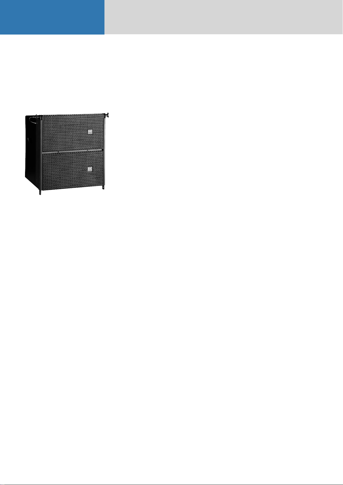
1. The CTA 208 Mid/High Unit
Fig. 1: CTA 208
Design and Construction
The CTA 208 Mid/High unit‘s top and bottom
panels slope at an angle of 4.5°. Water-repellent,
black PU lacquer coats the enclosure made of 18mm, 13-ply birch plywood. Your choices of array
curving angles (or splay) are 0° and 9°. The baffle
board cover consists of a metal grille; found behind
it are two CD horns equipped with acoustical lens
for the four 1" drivers.
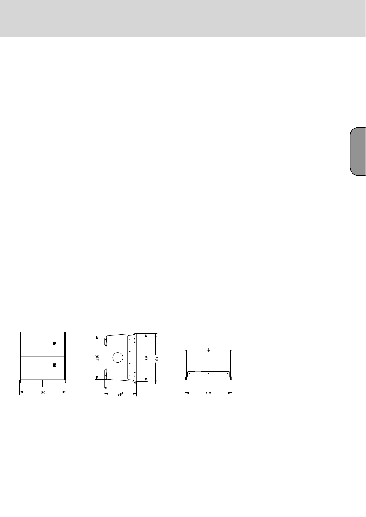
The CTA 208 weighs 29 kg. It is 51 cm wide, 52.5
cm high and 34.6 cm deep (including rigging
attachments). Two grips on the side panels simplify
transport and set-up.
Fully integrated rigging attachments comprising
three quick-release pins and three rigging
connectors, two mounted on the sides and one in
the rear, serve to fly the mid/high units.
Electrical and Acoustical Data
The CTA 208 enclosure features two 8" cone chassis
speakers and four 1" B&C high frequency drivers
with a front-mounted acoustical lens in a CD horn
configuration. An internal passive crossover with a
crossover frequency of 2 kHz addresses the drivers
via a special acoustic lens. The CTA 208 enclosure‘s
nominal electrical power-handling is 500 watts
RMS at 8 ohms impedance. It produces 105 dB
(1W@1m) sound pressure, measured under halfspace conditions. Maximum SPL measured under
the same conditions at one meter is 134 dB at 10%
THD. The CDR 108 radiates at a horizontal angle of
100°. Frequency response ranges from 95 Hz to 19
kHz (±3 dB).
1.1 Specifications, CTA 208
A professional two-way system featuring cylindrical
wave technology, this cabinet serves to set up
vertical line arrays and project a coherent wavefront
across the entire frequency range. The precisiontuned enclosure sports two 8" midrange speakers.
Four 1" high-frequency drivers address two constant
directivity horns with 100° horizontal directivity via
a special acoustic lens. Vertical directivity depends
on the number of CT A 208s in use.
The housing is made of 15/18-mm birch plywood
coated with black PU varnish. Its fully integrated
rigging hardware adjusts to two 0° and 9° angles
for setting up line arrays. An integrated pole mount
offers two tilt angles of 3° and 11°. An impactresistant steel grille covers the front.
The active CTA 118 Sub system subwoofer with
an integrated DDO-Pro™ Controller drives the
enclosure. CTA 208‘s frequency response (+- 3dB)
ranges from 95 hertz to 19 kHz. Axial sensitivity is
105 dB, measured under half-space conditions at @
1W / 1m. Maximum SPL measured under the same
conditions with two CTA 208s is 134 dB at 10%
THD. Each unit‘s nominal power handling is 500
watts RMS at 8 ohms.
Connectors: 1 Neutrik NL 4 Speakon.
Dimensions (W x H x D): 51 x 52.5 x 34.6 cm
Weight: 29 kg
Model: HK Audio CTA 208
Connections
The ports are out of harm‘s way on a recessed
connector panel on the CTA 208‘s back. It offers
one Speakon NL 4 connector. Pin assignments are
pin 1+ = mid/high +, 1- = mid/high-.
Page 4
1.2 The CTA 208 Enclosures‘ Technical Data
Nominal power handling/program/peak: .................. 500W RMS /1000W/ 1500W
Frequency response -10 dB 3): .................................... 80 Hz - 20 kHz
Frequency response+/-3 dB 3): ................................... 95 Hz - 19 kHz
Directivity: .................................................................. 100° horizontal
Sensitivity 1W@1m 1): ................................................ 105 dB
Max. SPL calculated 1): .............................................. 138 dB 2)
Max. SPL peak 1): ....................................................... 136 dB 3)
Max. SPL 1): ............................................................... 134 dB @ 10% THD (200 Hz- 5 kHz) 3)
Nominal impedance: .................................................. 8 ohms
Woofer/midrange speaker: ......................................... 2x 8"
High-frequency driver: ............................................... 4x 1", 2" voice coil
Crossover frequency: .................................................. 2 kHz, 12 dB/ octave
Connectors: ................................................................ 1 Speakon(r) NL 4
Housing (birch): ........................................................ 15/18 mm (1/2"), 9/13-ply
Angles up: .................................................................. 2x 4.5°
Finish: ........................................................................ Black 2-component PU lacquer
Grille: ......................................................................... Metal grille with black acoustic foam
Handles: .................................................................... Two slot grips routed into the side panels
Rigging hardware: ...................................................... DualCurve™, integrated with quick-release pins
Pole mount: ............................................................... HK Audio DuoTilt™
Weight: ....................................................................... 29 kg/ 63.8 lbs.
Dimensions (W x H x D): ........................................... 51 x 52.5 x 34.6 cm; 20" x 20 2/3" x 13 2/3"
Accessories: ............................................................... Touring flight case (2 CTA 208), rigging frame
25
English
1) Measured under half-space conditions2) Based on peak power handling 3) Measured with 2 CTA 208s
Fig. 2: CTA 208 housing dimensions in mm
English
Page 5
ConTour Array™ 1.0
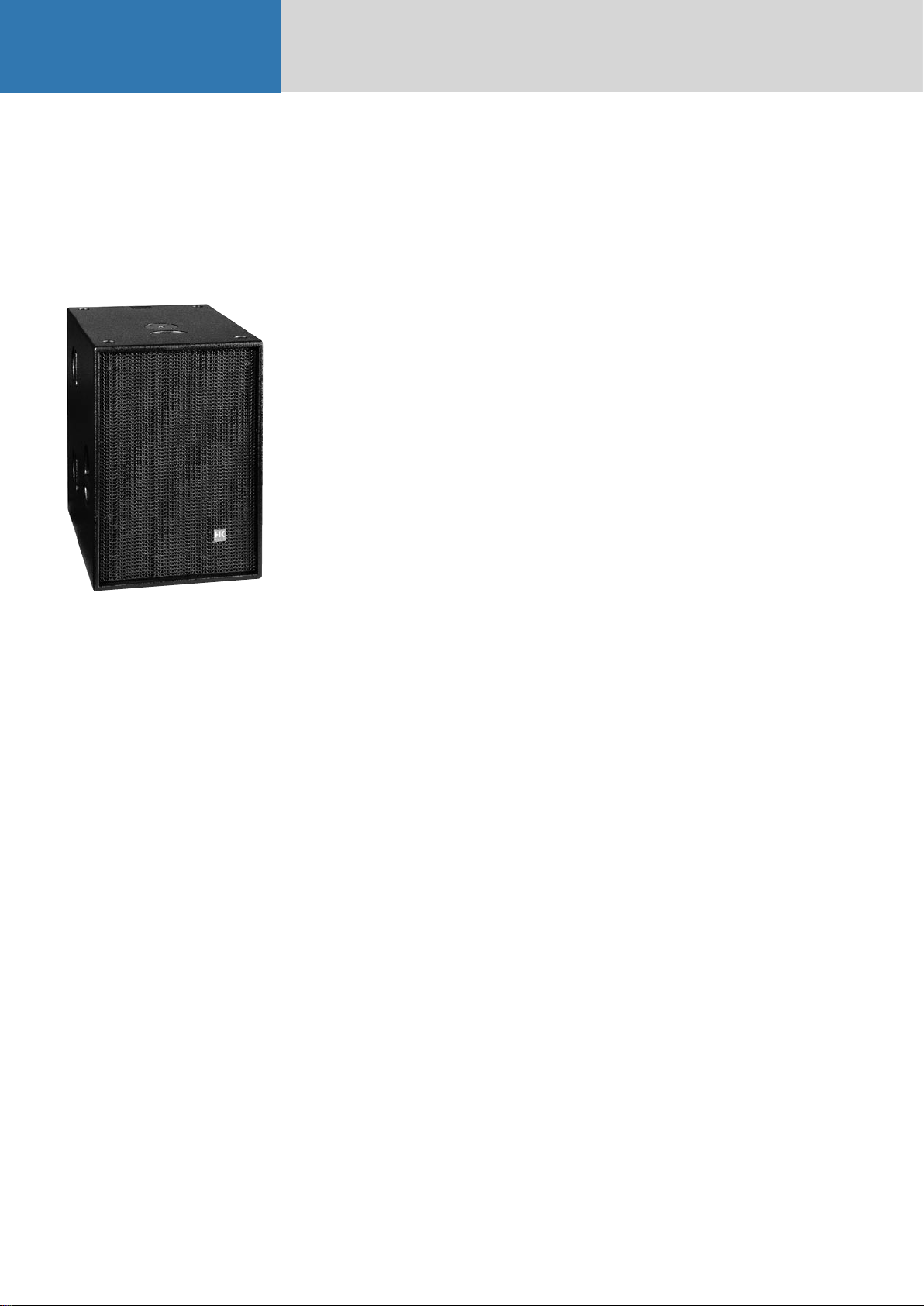
2. CTA 118 Sub
Fig. 3: CTA 118 Sub
Design and Construction
Made of 18-mm 13-ply birch plywood, waterrepellent, black PU lacquer coats the CTA 118
Sub enclosure. A robust metal grille backed with
laminated acoustic foam rubber covers the baffle
board.
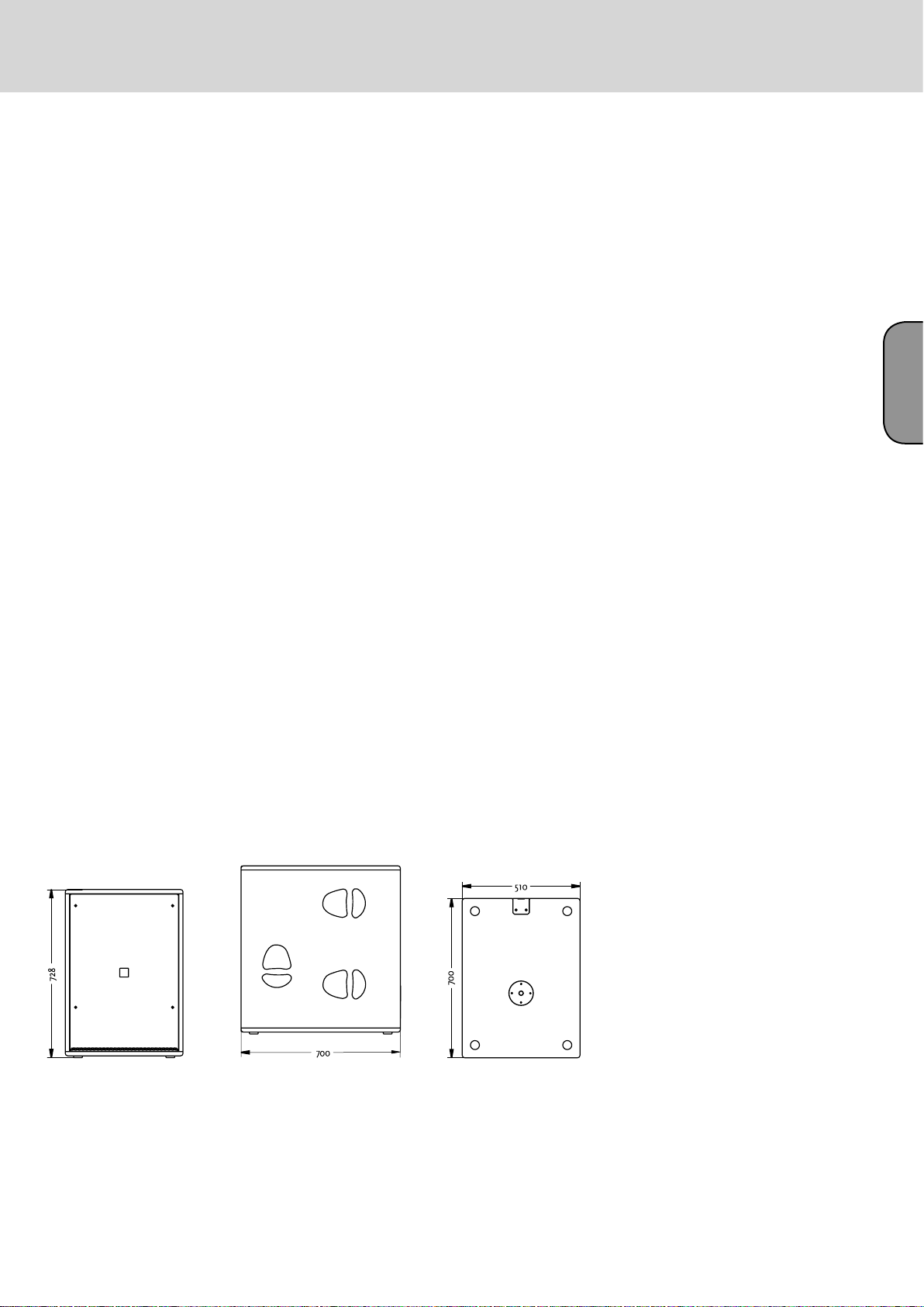
The CTA 118 Sub weighs 59 kg. It is 51 cm wide, 73
high and 71 cm deep. Three slot grips routed into
the side panels enable easy transport and set-up; a
recessed handle is on the lid. The active circuitry
resides in a separate chamber at the back of the
enclosure. A removable dolly protects the electronic
components and simplifies transport.
Electrical and Acoustical Data
The CTA 118 Sub enclosure features an 18" woofer.
The CTA 118 Sub enclosure‘s nominal electrical
power-handling is 700 watts RMS at 8 ohms
impedance. It produces 101 dB (1W@1m) sound
pressure, measured under half-space conditions.
Maximum SPL measured under the same conditions
at one meter is 130 dB at 10% THD. The CTA 118
Sub‘s frequency response ranges from 42 Hz to fx
(+/-3 dB). The two integrated PWM power amps
for the subwoofer and the mid/high output deliver
1000W RMS each.
2.1 Specifications, CTA 118 Sub
A professional active subwoofer equipped with a
DDO-Pro™ Controller and a 1000W RMS PWM
power amp, the CTA 118 Sub delivers excellent
impulse response and exceedingly dynamic lowfrequency response. It features an 18" woofer
mounted in a precision-tuned bass reflex enclosure.
Another 1000W RMS PWM power amp drives
HK Audio CTA 208 or ConTour Series™ speakers.
The rectangular block housing is made of 18-mm
birch plywood coated with black PU lacquer. An
impact-resistant steel grille covers the front. A
removabledolly protects the electronic components
and simplifies transport
Its frequency response ranges from the crossover
frequency down to 42 Hz (-3 dB) and 36 Hz (-10 dB).
Maximum SPL under half-space conditions is 130 dB
at 10% THD.
Connectors: 1 Neutrik NL 4 Speakon output, 1 XLR
female, 1 XLR male, 2 Powercon, 2 RJ45 Ethercon
Dimensions (W x H x D): 51 x 73 x 71 cm
Weight: 59 kg
Model: HK Audio CTA 118 Sub
Connections
Ports are out of harm‘s way on a recessed connector
panel on the CTA 118 Sub‘s back. It offers one
Speakon NL 4 connector. Pin assignments are pin
1+ = mid/high +, 1- = mid/high- . A Powercon mains
socket with another Powercon output connects to
the power supply. A female XLR and a male XLR port
serve to route signals. Two Neutrik Ethercon ports
serve to network several CTA 118 Subs.
Page 6
2.2 Technical Data, CTA 118 Sub
Integrated Power Amps:
Output power, Subwoofer: ...........................................1000 W RMS, Class D
Output power, Mid/High: ............................................1000 W RMS, Class D
Protection circuits: .......................................................DDO Pro™ Limiter, thermal protect, short-circuit
Line In/ Through: ........................................................ Female XLR, electronically balanced & floating
Mid/High Out: .............................................................1 Speakon(r) NL 4
Mains In/ Out: .............................................................2 Powercon
Networking/ Communication: .....................................DDO Pro™ Net/RS 485 Ethercon
Woofer: ........................................................................18"
Frequency response - 10 dB: ........................................36 Hz - fx
Frequency response+/- 3 dB: ........................................ 42 Hz - fx
Sensitivity 1W@1m 1): .................................................101 dB
Max. SPL calculated 1): ................................................134 dB 2)
Max. SPL peak 1): .........................................................133 dB
Max. SPL 1): .................................................................130 dB @ 10% THD (50 Hz- 200Hz)
Housing (birch): ..........................................................18 mm (3/4"), 13-ply
Surface coating: ...........................................................Black 2-component PU lacquer
Grille: ...........................................................................Metal grille with black acoustic foam
Handles: ......................................................................6 slot grips routed into the side panels, 1 on the lid
Pole mount: .................................................................M20
Weight: .........................................................................59 kg/ 129.8 lbs.
Dimensions (W x H x D): .............................................51 x 73 x 71 cm, 20" x 28 3/4" x 27 7/8"
Accessories: ................................................................. Protective cover, stack base plate
27
English
1) Measured under half-space conditions 2) Based on peak power handling
Fig. 4: CTA 118 Sub housing dimensions in mm
Page 7
ConTour Array™ 1.0
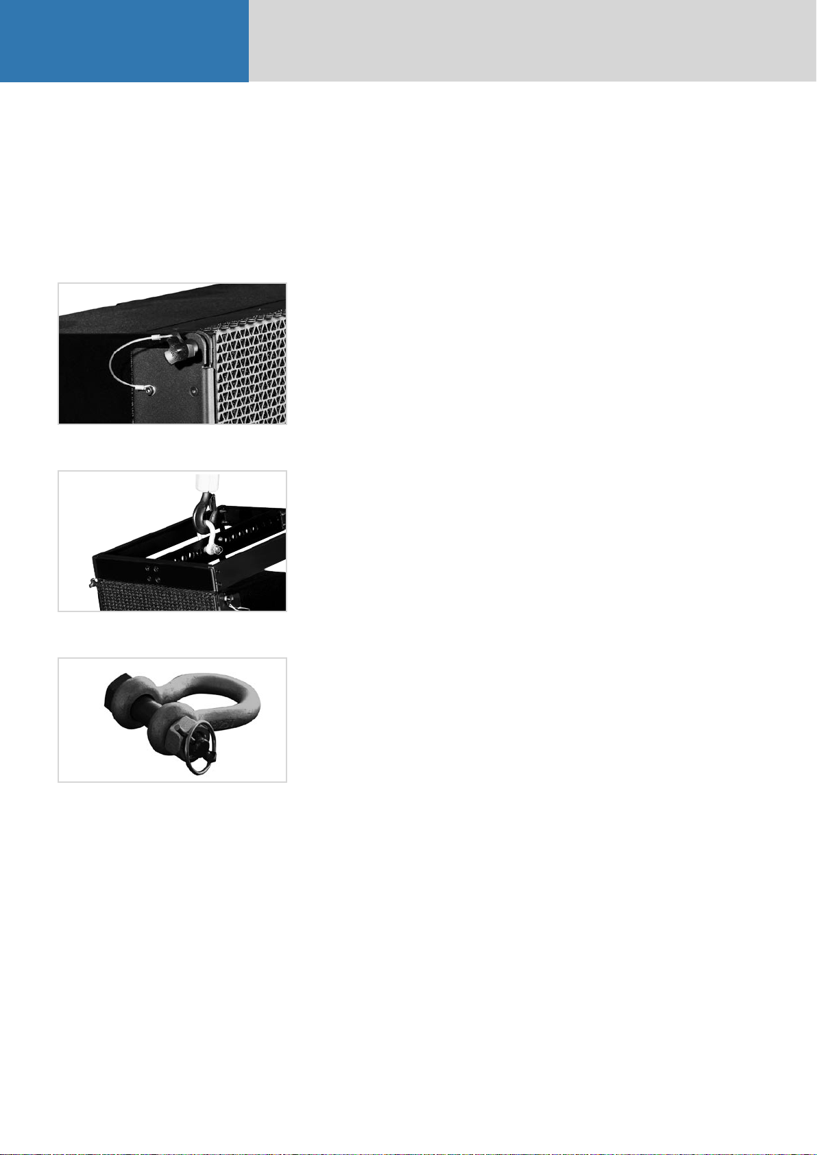
C. Rigging ConTour Array™ Enclosures
1. Components and Applications of
ConTour Array™ Rigging Hardware
Please also read the Notes on Rigging Safety in Chapter A of this manual.
Fig. 5: Integrated rigging attachments
Fig. 6: ConTour Array™ rigging frame
Fig. 7: Shackles for attaching motors, chain hoists
ConTour Array™ rigging hardware consists of the
following parts:
• a rigging frame with two shackles for attaching
motors or chain hoists.
• integrated rigging points on the side and back for
flying ConTour Array™ CTA 208 Mid/High units.
• three quick-release pins per CTA 208 for
connecting the enclosure to the rigging frame.
Important note on pins: Quick-release pins connect
rigging hardware and speaker enclosures, and their
proper function must be tested and verified. Pins
must always engage fully in the (fitted) hole. Under
no circumstances may these pins release on their
own when subjected to tractional forces. The nib in
the center of the pinhead must always be depressed
to insert pins; it releases the ball detents in front.
Once the pin engages in the hole, the nib must ease
back to its initial position.
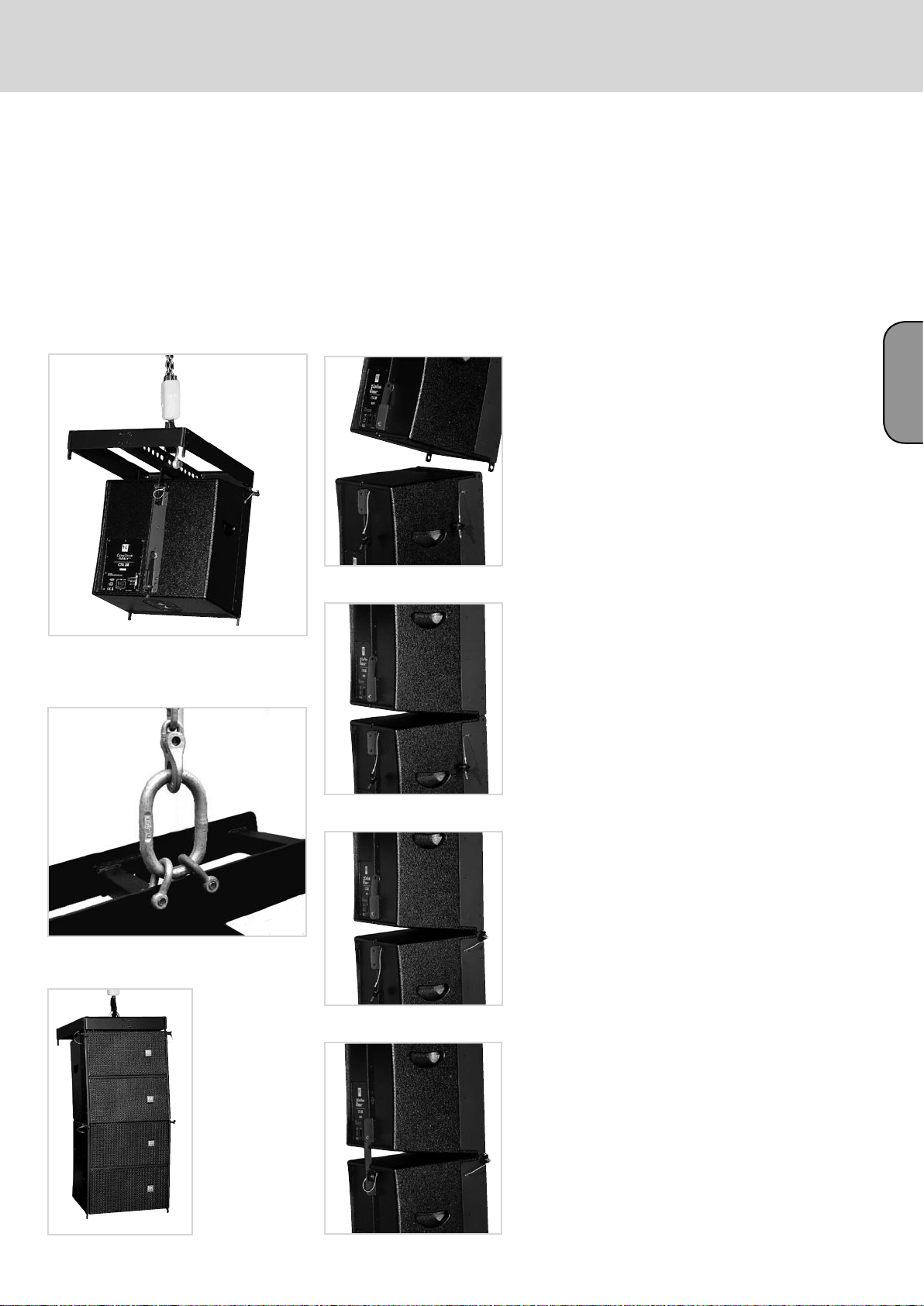
1.1 Mounting the Rigging Frame
It takes two people to perform these tasks. Remove
the quick-release pins from the enclosure. Set the
rigging frame on the enclosure. First attach the two
front connectors. Turn the rigging frame‘s connector
component down and slide it into the rear rigging
connector.
Insert the rear pin through the hole labeled 0°.
Attach to the rigging frame the shackle that accepts
the motor hook. Your choice of pick point depends
on how sharply you aim to curve the array later.
Tip: If you intend to rig additional enclosures, we
recommend that you attach all the required speaker
cords to the rigging frame now because this task
becomes more difficult as the array grows higher.
Be sure to use cords of sufficient length!
1.2 Setting the DualCurve™ Angle
Curve the two CTA 208 cabinets using the rear
connector component. You have two angles to
choose from, 0° and 9°. Remove the pin on the rear,
insert lead the connector into the rigging track and
secure the connector component with the pin as
pictured.
1.3 Rigging Additional
CTA 208 Mid/High Enclosures
Hoist the mounted CTA 208 Mid/High cabinets to a
height that allows you to roll a second case holding
two enclosures under the array. Remove the two
front pins from the enclosure you wish to mount.
Move the second case with two additional CTA 208s
into position. Slowly lower the top two cabinets
until the two front connectors engage. Insert the
two front pins first, ensuring they engage fully and
securely (see Figure 12 a). You may have to shift
the two enclosures slightly to ease the pins into
position. To attach the rear connector component,
you must swivel it out of the track and ensure it
faces down (see Figure 12 b). Insert the pin through
the hole labeled 0° or 9° as required.
Note: Depending on application, you may not be
able to select a pick point with a shackle. In this
case, use two shackles and a suitable O-ring as
shown in Figure 10.
Check all pins on the top rigging frame to ensure
they seat firmly. Attach the motor to the shackle.
Important: Ensure the motor‘s chain bag hangs
freely and does not rest on the rigging frame!
Engage the motor to lift the cabinet from the case.
Roll the case off to the side. Remove the two front
pins from the enclosure you wish to mount and fold
down its connector component. Now you can rig
further cabinets.
Hoist the array consisting of four CTA 208
enclosures high enough to remove it fully from the
case. Secure the hoisted array against blasts of wind
or unintentional twisting to prevent it from moving.
Page 8
29
English
Fig. 8: Mounting the rigging frame
Fig. 9: Setting an intermediate angle
Fig. 10: Hoisting the mounted CTA 208 enclosure
Fig. 11 a, b, c, d, e: Rigging additional CTA 208 enclosures
Page 9
ConTour Array™ 1.0
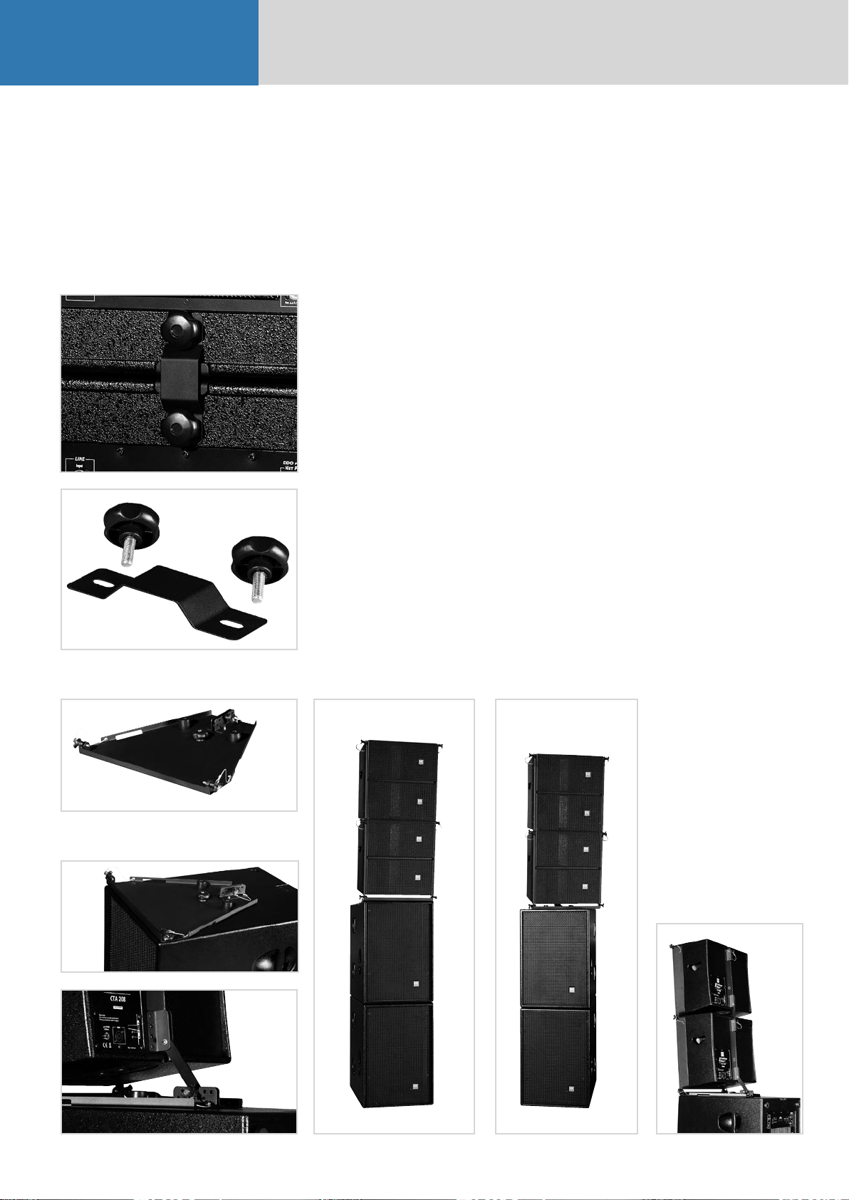
2. Groundstacking
3. Mains and Generator
Power Supply
Fig. 12 a, b: ConTour Array™ ground-stack connectors
Depending on application, use two or three
ConTour Array™ subwoofers as the stack‘s base. Set
the desired number of subwoofers on top of one
another.
Caution:
Secure the ground stack to prevent it from tipping!
Use the M10 bushings on the back of the CTA 118
subwoofer and the ground-stack connectors to do
this.
Mount mid/high units individually, one after
another, on the top CTA 118 Sub. Use the ConTour
Array™ stack plate as the base and connector to
the subwoofer. Attach it to the CTA 118 Sub’s pole
mount using the M20 thumb screw. The stack plate
lets you easily adjust mid/high units without having
to move the subwoofer. On this stack plate, you can
freely select the desired down-tilt between 0° and 9°
in 1.5° increments.
Connect no more than two CTA 118 Subs to one
mains phase (16 A). If you use the Powercon Link
port, connect no more than one further CTA 118
Sub. The 13-A limit on maximum input current (see
label) applies to Great Britain because UK power
cables are approved to 13 A only. 16-A current is
permissible in other countries using EU power
cables.
Caution: If you must power the CTA 118 Sub with a
generator, ensure the generator is running before
you switch the system on. Never switch systems
off and on with the help of the generator! This can
damage the PWM power amps’ switching power
supply!
Note: The Powercon Link is not available for 100120-volt units.
Fig. 13: ConTour Array™ stack plate
Fig. 14 a, b: Attaching the stackplate to the CTA 118 Sub
Fig. 15 a,b,c: CTA 208 Mid/High stack
Page 10

D. The ConTour Array™ DDO-Pro™ Controller
1. The DDO-Pro™ Net Port
31
Net Ports link several CTA 118 Subs in a
communication network. Use CAT 5 network cables
or professional Ethercon cables with a metal plug
to do this. Connect the first CTA 118 Sub’s output to
the next unit’s input, and so forth.
Note: This is purely a data interface. The DDO-Pro™
Net Port does not send audio signals.
If you wish to adjust controller settings (for example,
filter, gain or delay), you can do this on any CTA 118
Sub’s control panel. Automatically, the unit becomes
the master controller and sends parameter changes
to all networked CTA 118 Subs (up to 32 units).
Note: It does not send "Utilities" menu settings.
Caution: If you wish to use another CTA 118 Sub
and a ConTour Series™ cabinet (CT 108, CT 112, CT
115) for near-fill or in-fill applications alongside CTA
208 speakers in a larger rig, DO NOT network it!
Otherwise the connected CT 108, CT 112 or CT 115 will
adopt the settings entered for the mid/high array.
2. Audio Signal Routing
3.1 Level
You can adjust input levels from -96 dB to + 6dB in
0.5 dB steps. Use the Up or Down keys to select the
gain setting and confirm your selection with Enter.
Note: The Level parameter adjusts the level after the
analog-to-digital converter to balance out varying
(system) levels. Level does not influence the input
signal’s volume in front of the analog-to-digital
converter. If the display reads “Digital Clip ?! Check
Input !” be sure to reduce the level at the mixing
console. In this case, the signal is saturating the
analog-to-digital converter, distorting the signal’s
rectangular waveform to create square waves. This
sounds extremely annoying and will eventually
destroy the power amp and speakers.
Tip: If you wish to reduce the volume of the lower
mid/high unit in the array – say, because it hangs
low and listeners are close to this unit – you can
use Level to do this. However, Level also affects the
subwoofer’s volume. Increase Sub Level by the same
value to compensate for the difference.
3.2 Key Lock
English
Fig. 16: DDO-Pro™ network
Use an XLR cord to connect the signal source to
the first CTA 118 Sub’s signal input. If you wish to
connect further CTA 118 Subs to the source, do this
using the Signal Through ports. The XLR port’s pin
assignments are: pin 1 = ground, 2=+, 3=-.
Be sure to read section 3.1 covering maximum input
signal level and digital clip error and heed these
guidelines.
3. Handling the
DDO-Pro™ Controller
Four keys operate the device - Menu, Enter, Up and Down.
Menu/ Esc:
This key accesses the controller’s menu structure
and exits a menu level.
Enter:
This key confirm changes and access menu levels.
Up and Down:
These keys navigate within a menu level and
increase and decrease displayed values. Please refer
to the menu structure quick guide at the end of the
chapter to learn more.
3.3 Utilities
Sync Remote
When you confirm the Sync Remote command, the
unit sends the current settings to all networked
controllers. The control panel currently in use is the
master. This feature comes in handy if the network
connection fails.
Noise Reduction
You can activate Noise Reduction on demand. It
mutes signal paths when the rig is off-line. The unit
ships with this feature deactivated.
LCD Contrast
Adjust the display’s contrast to taste using the Up or
Down keys. Confirm your selection with Enter.
Factory Reset
When you confirm this function, ALL settings reset
to their factory defaults. For example, you could use
it to set all delays to 0 ms and levels to 0 dB.
Fig. 17: DDO-Pro™ Controller panel
The AD converter’s Digital Clip indicator
Page 11

ConTour Array™ 1.0
2 x CT108 1 x CT112
Delay Base
Select the preferred delay display reading - meters
(m), feet (ft) or milliseconds (ms). Select the
option with the Up or Down keys and confirm your
selection with Enter.
3.4 Sub Delay
Sub Delay is a time alignment tool, that is, it
compensates differences in mid/high units’ and
subwoofers’ response times. Like Sub Level, Sub
Delay controls subwoofers’ and mid/high units’
relative delay.
For example, if you place subwoofers well in front
of mid/high units, you must delay the subwoofers
accordingly. Do this by adjusting a positive
delay value in the Sub Delay menu. If you place
subwoofers well behind mid/high units, you must
enter negative values to compensate.
Caution: Negative Sub Delay values delay the signal
path from the subwoofer to the mid/high unit,
causing overall system latency! Experience has
shown that this method compensates differences of
15 ms or 5 m without latency problems. The control
range sweeps from -30 ms to 29.6 ms.
3.6 Sub Level
You can adjust the balance of volumes between the
subwoofer and mid/high unit from -12 dB to + 6dB
in 0.5 dB steps. Use the Up or Down keys to select
the Sub Level and confirm your selection with Enter.
3.7 System Setup
A special filter preset is available for each
configuration (see fig. 19 a-f). Be sure to assign
the same preset to each DDO-PRO™ controller for
every configuration (1 to 4 CTA 208s). Use the Up
or Down keys to select the right preset and confirm
your selection with Enter.
1 x CT115 1 x CTA208
4 x CTA208
Fig. 18 a, b, c, d, e, f: System Setups
3.5 Delay
Delay controls the overall delay of a system
comprised of subwoofers and mid/high units. The
highest setting is 72.6 ms.
Page 12

3.8 Quick Guide to the V1.01 Controller’s Menu Structure
33
English
Fig. 19: Menu structure of the DDO-PRO™ Controller
English
Page 13

E. Service
1. Maintenance
35
Regularly check the vents to ensure air flows freely
in and out. Clean the foam rubber filters whenever
necessary. Remove the vent grille on the back to do
this.
2. ConTour Array™
Spare Parts
Note:
• If your equipment needs service, please turn to
your HK Audio dealer or the HK Audio distributor in
your country. They stock the required spare parts.
• In the event of a defect, always indicate the
defective device’s serial number. This way the HK
Audio service team can immediately find out if an
update is available for your product.
• Use only original HK Audio replacement speakers
and parts! Most were developed especially for HK
Audio products and are not available direct from
speaker manufacturers!
3. Replacing Loudspeakers
and Voice Coils
3.1 1", 8" and 18" Speakers
Proceed as follows to replace the given speaker:
• Unfasten and remove the Phillips screws holding
the grille in place. Remove the grille. These screws
are on the CT 118 Sub’s front panel and the CTA
208’s side and bottom panels.
• Unfasten and remove the hex head bolts holding
the speaker in place.
• The speaker is now detached. Disconnect the
speaker wires.
3.2 The Drivers’ Voice Coils
Proceed as follows to replace the drivers’ voice coils:
• Remove the front grille as described above.
• Unfasten the four screws holding the horn yoke
and remove the horn and driver from the baffle.
Disconnect the wires connecting the driver. Ensure
correct polarity when installing and connecting
a replacement speaker! Red= positive, black =
negative
• Unfasten the voice coil housing’s hex head bolts
using a 3-mm wrench.
• Take the lid off the voice coil housing.
• Replace the voice coil.
Important note: Replace the voice coil in a clean
working environment only. Be sure to keep dust
and dirt out of the open driver. If despite your
precautions particles manage to get in, use a strip
of adhesive tape to remove them or carefully blow
compressed air into the back of the driver to whisk
the particles out. When installing the new voice
coil, ensure it is centered properly. Proceed as
follows to check this:
Close the cover of the voice coil housing and
reconnect the cords (red = positive, black =
negative). Feed a sine wave signal with a frequency
between 1000 Hz and 1500 Hz into the mid/high
enclosure’s input. Sweep through the frequency.
If you hear abrasive noises like crackling or
scratching, the voice coil is not centered properly.
Reopen the voice coil chassis and turn the voice coil
a bit until it renders the signal cleanly!
4. Checking Speakers’ Phase
As a precaution, always check the components’
phase using a suitable phase-checker after replacing
speakers. To do this, connect the CTA 208 mid/high
unit to the CTA 118 Sub using a Speakon cord.
Note: If you are checking the CTA 208 mid/high
unit in passive mode with an external power amp,
you will get a different phase reading! Therefore
always use the CTA 118 Sub for phase checks.
Connect the phase-checker to the CTA 118’s signal
input. It may be advisable to lower the input level on
the DDO-Pro™ Controller!
The speakers’ phases should read as follows:
With CTA 118 Sub:
18" woofer: In phase (+)
8" speaker: Out of phase (-)
1" driver: In phase (+)
CTA 208 passive:
8" speaker: In phase (+)
1" driver: Out of phase (-)
English
Caution: When installing and connecting a
replacement speaker, ensure the polarity is correct!
Red= positive, black = negative
Page 14

DRAWING-NUMBERS
EXAMPLE
HK0106-EX-R01-1A
VERSION
SERIAL NUMBER
DEPARTMENT:
R = R&D
REVISION
PROJECT-NR.:
HK = HK AUDIO
HU = HUGHES&KETTNER
MP = MINDPRINT
CHARACTER:
BL = SHEET METAL / BLECH
EX = EXPLODED DRAWING / EXPLOSIONSZEICHNUNG
HZ = CABINET / HOLZGEHÄUSE
KU = PLASTIC / KUNSTSTOFF
LP = PCB / LEITERPLATTEN
SO = MISCELLANEOUS / SONSTIGES
SP = SCHEMATIC / SCHALTPLÄNE
TR = TRANSFORMER / TRANSFORMATOR
GK = WIRING DIAGRAM / GERÄTEVERKABELUNG
Page 15

Stand
W
Y
r
Standard for single wire confection.
16 B 150 638 I - 485 W Z I 1015
style 1015 according UL specifications
I = completely insulated with black shrinktube or appropriate sleeve
IT = partly insulated; only crimp connection insulated.
no marking = without insulation
Z = with additional junction
no marking = without additional junction
W = angled faston
no marking = straight faston
17. Jun 04
Faston connector brass tin-plated DIN 46245
638 = 6,3 * 0,8 [mm]
488 = 4,8 * 0,8 [mm]
485 = 4,8 * 0,5 [mm] if fully insulated (I) insulation with blue shrinktube
if partly insulated (IT) use IF 602 485 .
288 = 2,8 * 0,8 [mm]
285 = 2,8 * 0,5 [mm] if fully insulated (I) insulation with blue shrinktube
if partly insulated (IT) use IF 602 485
abiso = 5mm bared and tin-plated (teilabzug)
text for special constructions, (for example. 4mm ringshaped faston)
the larger faston connector always mentioned at first. (Nathan drawing number controlling)
lenght in mm within a 50 mm raster
colour
B = black (phase conductor)
R = red
BR = brown
BL = blue (neutral conductor)
= white
G = yellow-green (ground bonding/ earthing connection)
cross section
16 = AWG 16 (prefered usage)
Q1.5 = H07VK 1,5mm² (prefered usage)
wire designation:
P + lfd Nr. = AWG single wire black, red, blue, brown or white
E + lfd Nr. = AWG single wire green- yellow
L + lfd N
FQL + lfd Nr. = crossover wiring H07VK
Regarding special wirings like wiring harness or similar, drawings will be prepared and appropriate
. = twisted AWG double wire, lenght specification always in twisted condition
drawing numbers will be stored in the article archive.
Page 16

Confidential, for authorized service technicians only! Do not disclose
this information to or share these documents with third parties.
TECHNICAL SERVICE:
Stamer Musikanlagen GmbH • Magdeburger Str. 8 • 66606 St.Wendel • Germany
Music & Sales P.E. GmbH • Leipziger Str. 3 • 66606 St.Wendel • Germany
Service Documents
HK1805
CTA
CTA 208
MID/HIGH UNIT
Page 17

HK1805-BL-R06-1A
9E 970820
39 E 976094
HK1805-BL-R11-1A
41
14E 970825
26
30
19 E 974006
23 E 974068
41
20
23
32
17
7
17
8
3 E 400281
HK1805-HZ-R01-1C
15 E 972008
HK1805-SO-R05-1A
HK1805-BL-R08-1A
HK1805-EX-R08-1B
11E 970822
31E 974322
14
27
4E 520126
47E 994108
26 E 974216
42 E 976170
26
30 E 974272
6 E 970798
HK1805-BL-R12-1A
12 E 970823
HK1805-BL-R09-1A
27 E 974233
48E 994166
38 E 975414
13 E 970824
24E 974168
5
39
16 E 972032
HK1805-SO-R06-1A
HK1805-BL-R10-1A
28 E 974243
7 E 970799
HK1805-BL-R05-1B
10 E 970821
HK1805-BL-R07-1A
34 E 974497
40 E 976113
21E 974024
29E 974258
HK1805-EX-R05-1B
24
1E 1135
25
49 E 994196
18 E 974004
22 E 974041
HK1805-BL-R04-1A
8E 970819
17
HK1203-BL-R02-1D
23
5E 970664
35 E 974506
20 E 974020
41 E 976157
32 E 974453
17E 972088
33 E 974492
HK1805-KU-R02-1A
36E 974527
ÄNDERUNG
INDEX
1B
drawing-nr. update C. Loris
37E 974528
ZEICHNER
2 E 1136
HK1805-EX-R06-1B
25 E 974191
66606 St. Wendel / Germany
ZEICHNUNGS-NR.:
ERSTELLT VON:
GEPRÜFT/
FREIGEGEBEN VON:
WERKSTOFF:
DATEINAME:
HK1805-EX-R07-1B
C. LORIS 1
HK1805-EX-R07-1B-TOP-GESAMT
TITEL:
HK1805-CTA 208 COMPLETE
EXPLODED DRAWING
VERSION:
AM:
29.05.2006
AM:
OBERFLÄCHE:
/
REVISION:
BLATT:
2
B1
BLÄTTER
Page 18

Pos. part-no. 1 description Beschreibung quantity
1 1135 HK1805-Top front grill assembly above HK1805-Top Frontgitterbaugruppe oben 1
2 1136 HK1805-Top front grill assembly below HK1805-Top Frontgitterbaugruppe unten 1
3 400281 Cabinet ConTour CTA 208 Holzgeh. ConTour CTA 208 1
4 520126 Crossover ConTour CTA 208 Freqw. ConTour CTA 208 1
5 970664 front rigging system, connector bottom Blech CDR 108 Einlage Mitte 2
6 970798 sheet metal ConTour CTA 208 connector Blech ConTour CTA Verbinder
1
Flugmechanik
7 970799 sheet metal ConTour CTA 208 front block Blech ConTour CTA 208 Front Klotz 2
8 970819 front rigging system, inner mounting plate Blech CTA 208 Einlage Innen 2
9 970820 front rigging system, left outer mounting plate Blech CTA 208 Flugwinkel vo-li 1
10 970821 front rigging system, right outer mounting plate Blech CTA 208 Flugwinkel vo-re 1
11 970822 sheet metal CTA 208 rear base plate Blech CTA 208 Montageplatte 1
12 970823 rear rigging system, right mounting part Blech CTA 208 Flugwinkel hi-re 1
13 970824 rear rigging system, left mounting part Blech CTA 208 Flugwinkel hi-li 1
14 970825 sheet metal CTA 208 angle adjuster Blech CTA 208 Winkeleinsteller 2
15 972008 damping wool Dämmwolle Hochbauschlvlies 1
16 972032 eggbox foam anthracite Noppenschaumstoff anthrazit 1
17 972088 rubber punching CTA 208 Gummi-Stanzteil CTA 208 4
18 974004 hexagon socket head cap screw, M4x25, zinc plated Inbusschraube M4*25 vz 8
19 974006 hexagon socket head cap screw, M5x25, black Inbusschraube M5 x 25sw 1
20 974020 hexagon socket head cap screw, M5x20, black Inbusschraube M5x20sw 2
21 974024 hexagon socket head cap screw, M5x55, black Inbusschraube M5x55 sw 6
22 974041 hexagon socket countersunk head screw, M6x30, black Inbussenkschraube M6x30 sw 6
23 974068 washer, form A, D=5.3mm, zinc plated Unterleg-Scheibe 5,3 vz 3
24 974168 washer, form A, 5.3*12, zinc plated Unterleg-Scheibe 5,3*12 vz 12
25 974191 cross recessed raised countersunk screw, M4x20, black Linsensenkschraube M4*20 sw 8
Pos. part-no. 1 description Beschreibung quantity
26 974216 hexagon socket countersunk head screw, M5x25, black Inbussenkschraube M5x25 sw 10
27 974233 washer, form A, D=6.4mm, zinc plated Unterleg-Scheibe 6,4 vz 2
28 974243 self locking hexagon nut with plastic insert, M6, zinc
Stopmutter M6 vz 1
plated
29 974258 hexagon socket head cap screw, M5x40, black Inbusschraube M5 x 40 sw 6
30 974272 cross recessed raised countersunk screw, M5x10, black Linsensenkschraube M5*10 sw 8
31 974322 ABC-Spax-S screws for backwall, 4x20, black Rückwandschraube, 4*20 sw 10
32 974453 hexagon socket countersunk head screw, M5x16, black Inbussenkschraube M5x16 sw 14
33 974492 plastic PCB spacer, 4.2x8x35, Polyamid black Dist.Hülse PE 4,2*8*35 [mm] 1
34 974497 sleeve M4x10mm Eindrehmuffe M4x10mm 2
35 974506 hexagon socket head cap screw, M6x26, black Inbusschraube M6*26 sw 1
36 974527 cross recessed panhead screw, M4x25, black Linsenschraube M4 x 25 sw 1
37 974528 cross recessed panhead screw, M4x40, black Linsenschraube M4 x 40 sw 1
38 975414 PCB spacer, 6x11.5x7.5, brass, nickel plated Dist.Hülse 6,0*11,5*7,5 [mm] 1
39 976094 plastic dish 3403 HKBS! DART ! Griffschale 3403 HKBS! DART ! 2
40 976113 flange for speaker stand, plastic, DuoTilt Ständerflansch, Kunst., zweifach 1
41 976157 self locking clamping pin KSB2234 8x17 Kugelsperrbolzen KSB2234 8x17 3
42 976170 magnetic clamp HL25A Haftmagnet HL25A 1
43* 982037 sealing tape 2x6mm Iso-Zell-Band fadenvers. 2*6mm 6,38 lfdm
44* 982044 sealing tape 2x15mm Iso-Zell-Band fadenvers. 2*15mm 0,33 lfdm
45* 986015 foam glue, Jowatac Schaumstoffklebstoff Jowatac xxx
46* 988165 1k polyurethane glue, 310mltrs. tube Polyurethan 1-K Kleber, 310ml Kartusche xxx
47 994108 B&C DE 12-8 80HM 1" Driver B&C DE 12-8 80HM 1" Driver 4
48 994166 Wavetransformer CDR 108 Horn Wavetransformer CDR 108 2
49 994196 SICA LP 209.65/N220 T 4 Ohms SICA LP 209.65/N220 T 4 Ohms 2
ÄNDERUNG
INDEX
1B
drawing-nr. update C. Loris
ZEICHNER
66606 St. Wendel / Germany
ZEICHNUNGS-NR.:
ERSTELLT VON:
GEPRÜFT/
FREIGEGEBEN VON:
WERKSTOFF:
DATEINAME:
HK1805-EX-R07-1B
C. LORIS 2
HK1805-EX-R07-1B-TOP-GESAMT
TITEL:
HK1805-CTA 208 COMPLETE
EXPLODED DRAWING
VERSION:
AM:
29.05.2006
AM:
OBERFLÄCHE:
/
REVISION:
BLATT:
2
B1
BLÄTTER
Page 19

Pos. part-no. 1 description Beschreibung quantity
1 970816 CTA 208 front grill assembly above Frontgitter ConT. CTA 208 oben 1
2 972086 CTA 208 acoustic foam anthracite 5mm Akustikschaum Anthrazit 5mm 1
3 980251 logo 'hk'ConTourSer. 35x35x3mm Logo 'hk'ConTourSer. 35x35x3mm 1
2 E 972086
HK1805-SO-R07-1A
ÄNDERUNG
INDEX
item-nr. update, drawing-nr.
1B
update
1E 970816
HK1805-BL-R01-1D
ZEICHNER
C. Loris
service-nr.: E1135
TITEL:
HK1805-CTA 208 UPPER FRONT GRILLE
EXPLODED DRAWING
66606 St. Wendel / Germany
ZEICHNUNGS-NR.:
3E 980251
ERSTELLT VON:
GEPRÜFT/
FREIGEGEBEN VON:
WERKSTOFF:
DATEINAME:
HK1805-EX-R05-1B
C. LORIS 1
HK1805-EX-R05-1B-FRONTGITTER-TOP-OBEN
OBERFLÄCHE:
VERSION:
AM:
29.05.2006
AM:
/
REVISION:
BLATT:
1
B1
BLÄTTER
Page 20

Pos. part-no. 1 description Beschreibung quantity
1 970817 CTA 208 front grill assembly below Frontgitter ConT. CTA 208 unten 1
2 972086 CTA 208 acoustic foam anthracite 5mm Akustikschaum Anthrazit 5mm 1
3 980251 logo 'hk'ConTourSer. 35x35x3mm Logo 'hk'ConTourSer. 35x35x3mm 1
1E 970817
HK1805-BL-R02-1D
2 E 972086
HK1805-SO-R07-1A
ÄNDERUNG
INDEX
item-nr. update, drawing-nr.
1B
update
ZEICHNER
C. Loris
service-nr.: E1136
TITEL:
3E 980251
66606 St. Wendel / Germany
ZEICHNUNGS-NR.:
ERSTELLT VON:
GEPRÜFT/
FREIGEGEBEN VON:
WERKSTOFF:
DATEINAME:
HK1805-EX-R06-1B
C. LORIS 1
HK1805-EX-R06-1B-FRONTGITTER-TOP-UNTEN
HK1805-CTA 208 LOWER FRONT GRILLE
EXPLODED DRAWING
OBERFLÄCHE:
VERSION:
AM:
29.05.2006
AM:
/
REVISION:
BLATT:
1
B1
BLÄTTER
Page 21

Pos. part-no. 1 description Beschreibung quantity
1 520126 Crossover ConTour CTA 208 (PCB) Freqw. ConTour CTA 208 (Platine) 1
2 952022 speakon chassis connector, NL4MP Speakonbuchse 4pol eckig 1
3 970818 Connecting Plate CTA 208 Blech Anschlussplatte CTA 208 1
4 974110 self locking hexagon nut with plastic insert, M3, zinc plated Stopmutter M3 vz 2
5 974290 self locking hexagon nut with plastic insert, M4, zinc plated Stopmutter M4 vz 4
6 974363 hexagon PCB spacer, type B, M4x10, zinc plated Dist. Bol Innen/Außengew. M4*10 vz 4
7 974444 cross recessed raised countersunk screw, M3x12, black Linsensenkschraube M3*12 sw 2
6E 974363
1E 520126
HK1805-SP-R05-1B
3 E 970818
HK1805-BL-R03-1B
7 E 974444
ÄNDERUNG
INDEX
1B drawing-nr. update C. Loris
replacement of cables F. Sitter
1C
ZEICHNER
2 E 952022
5E 974290
4 E 974110
TITEL:
HK1805-CTA 208 FQW complete
EXPLOSIONSZEICHNUNG
66606 St. Wendel / Germany
ZEICHNUNGS-NR.:
ERSTELLT VON:
GEPRÜFT/
FREIGEGEBEN VON:
WERKSTOFF:
DATEINAME:
HK1805-EX-R08-1C
C. LORIS 1
HK1805-EX-R08-1C-TOP-FQW
OBERFLÄCHE:
VERSION:
AM:
30.05.2006
AM:
N/A
REVISION:
BLATT:
3
C1
BLÄTTER
Page 22

1
ÄNDERUNG
INDEX
1B drawing-nr. update C. Loris
replacement of cables F. Sitter
1C
ZEICHNER
66606 St. Wendel / Germany
ZEICHNUNGS-NR.:
ERSTELLT VON:
GEPRÜFT/
FREIGEGEBEN VON:
WERKSTOFF:
DATEINAME:
HK1805-EX-R08-1C
C. LORIS 2
HK1805-EX-R08-1C-TOP-FQW
TITEL:
HK1805-CTA 208 FQW complete
EXPLOSIONSZEICHNUNG
VERSION:
AM:
30.05.2006
AM:
OBERFLÄCHE:
N/A
REVISION:
BLATT:
3
C1
BLÄTTER
Page 23

-
+
-
962144 stranded wire BB600/2 black 230mm
16-B-230-638I-638I 1015
962060 stranded wire FQL16 black 550mm
Q1.5-B-550-638-bared
962216 stranded wire FQL15 black 850mm
Q1.5-B-850-638-bared
-
-
+
-
-
+
-
+
ÄNDERUNG
INDEX
1B drawing-nr. update C. Loris
replacement of cables F. Sitter
1C
ZEICHNER
+
-
+
962144 stranded wire BB600/2 black 230mm
16-B-230-638I-638I 1015
962059 stranded wire FQL16 red 550mm
Q1.5-R-550-638-bared
962215 stranded wire FQL15 red 850mm
Q1.5-R-850-638-bared
+
+
-
962613 stranded wire blue 650mm
16-BL-650-638-638 1015
962060 stranded wire FQL16 black 550mm
Q1.5-B-550-638-bared
962059 stranded wire FQL16 red 550mm
Q1.5-R-550-638-bared
Pos. part-no. 1 description Beschreibung quantity
1 962007 stranded wire Q1.5-R-150-485I-bared Litze Q1.5-R-150-485I-bared 1
2 962008 stranded wire Q1.5-B-150-485I-bared Litze Q1.5-B-150-485I-bared 1
3 962059 stranded wire Q1.5-R-550-638-bared Litze Q1.5-R-550-638-bared 2
4 962060 stranded wire Q1.5-B-550-638-bared Litze Q1.5-B-550-638-bared 2
5 962144 stranded wire 16-B-230-638I-638I 1015, AWG Litze 16-B-230-638I-638I 1015, AWG 2
6 962215 stranded wire Q1.5-R-850-638-bared Litze Q1.5-R-850-638-bared 1
7 962216 stranded wire Q1.5-B-850-638-bared Litze Q1.5-B-850-638-bared 1
8 962613 stranded wire 16-BL-650-638-638 1015, AWG Litze 16-BL-650-638-638 1015, AWG 1
+
962008 stranded wire FQL4 black 150mm
Q1.5-B-150-485I-bared
962007 stranded wire FQL4 red 150mm
Q1.5-R-150-485I-bared
1+
1-
66606 St. Wendel / Germany
ZEICHNUNGS-NR.:
ERSTELLT VON:
GEPRÜFT/
FREIGEGEBEN VON:
WERKSTOFF:
DATEINAME:
-
+
TITEL:
HK1805-CTA 208 FQW complete
EXPLOSIONSZEICHNUNG
OBERFLÄCHE:
VERSION:
AM:
30.05.2006
AM:
N/A
HK1805-EX-R08-1C
C. LORIS 3
HK1805-EX-R08-1C-TOP-FQW
REVISION:
BLATT:
3
BLÄTTER
C1
Page 24

Pos. part-no. 1 description Beschreibung quantity
1 948037 retaining spring for axial power resistor SI-Halter f. 10W Widerstand 1
2 948038 retaining spring for 20W axial power resistor SI-Halter f. 20W Widerstand 1
3 970826 sheet metal CTA 208 crossover protection Blech CTA 208 Schutzblech FWQ 1
4 974097 blind rivet alu/steel standard, 5.0x6.0 Blindniete Alu-FLARUKO 5,0*6,0 1
5 974098 hexagon nut, class 8, M5, brass Sechskantmutter M4 ms 4
6 974103 toothed lock washer, D=4.3, AZ, zinc plated Fächer-Scheibe az, 4,3 vz 8
7 974107 plastic PCB spacer, 4.2x8x10, Polyamid black Dist.Hülse PE 4,2*8*10 [mm] 2
Pos. part-no. 1 description Beschreibung quantity
8 974121 slotted cheese head screw, M4x35, brass Zylinderschraube M4*35 ms 2
9 974135 spread rivet, polyamid PA6, 4x5, black PA-Spreizniet D=4mm L=5mm 3
10 974161 hexagon head screw, M4x12, brass Sechskantschraube, M 4*12 ms 2
11 974234 washer, form A, D=4.3mm, zinc plated Unterleg-Scheibe 4,3 vz 6
12 974473 blind rivet alu/steel standard, 4.0x6.0 Blindniete Alu-FLARUKO 4,0*6,0 1
13* 988011 silicon glue, 310mltrs tube Silicon transparent, 310ml Kartusche xxx
14* 988165 1k polyurethane glue, 310mltrs. tube Polyurethan 1-K Kleber, 310ml Kartusche xxx
9 E 974135
3 E 970826
HK1805-BL-R29-1B
10 E 974161
ÄNDERUNG
INDEX
1B drawing-nr. update
ZEICHNER
C. Loris
5E 974098
2E 948038
6E 974103
6 E 974103
11 E 974234
7E 974107
11 E 974234
11E 974234
6E 974103
1E 948037
4 E 974097
8E 974121
12 E 974473
6 E 974103
5 E 974098
66606 St. Wendel / Germany
ZEICHNUNGS-NR.:
ERSTELLT VON:
GEPRÜFT/
FREIGEGEBEN VON:
WERKSTOFF:
DATEINAME:
TITEL:
HK1805-CTA 208 FQW
EXPLODED DRAWING
OBERFLÄCHE:
VERSION:
AM:
29.05.2006
AM:
N/A
HK1805-EX-R09-1B
C. LORIS 1
HK1805-EX-R09-1B-TOP-FQW-Platine
REVISION:
BLATT:
1
BLÄTTER
B1
Page 25

9 6
5
4
3
7
1
8
626
INDEX CHANGES
Spa re Par ts List for: HK1805-LP-R05-1A
Pr oj ec t: CTA
Project Number: HK1805
Assembly: Crossoverboard
pos. part no. description Bezeichnung re ference des ignators quantity
1 930004 passiv e cros sover coil, 0.33mH/0.71mm_LU Luftspule 0,71mm 0,33mH L2 1
2 930013 passiv e cros sover coil, 1.50mH/1.00mm_LU Lufts pule 0,95 mm 1,5 mH L1 1
3 930043 passiv e cr ossov er coil, I-core, 2.20mH/0.80mm_LI I-Kernspule 0,8mm 2,2 mH L3 1
4 911124 axial high pow er ceramic resistor, 10R/20W_AX Drahtw id. axial 10,0 Ohm 20W R1 1
5 911032 axial high pow er ceramic resistor, 33R/10W_AX Drahtw id. axial 33,0 Ohm 10W R3 1
6 952047 Faston-Stecker Printmontage 4.8mm stehend,
7 928003 passiv e crossover capacitor, MKP-3.3u/250V MKP Kondensator 250V 3,3 µF C2 1
8 928019 passiv e crossover capacitor, MKP-3.9u/250V MKP Kondensator 250V 3,9 µF C1 1
9 928018 passiv e crossover capacitor, MKP-18u/250V MKP Kondensator 250V 18 µF C3 1
FASTON-4.8-ST
Flachstecker 4,8x0,8 Gprint JP1,JP2,JP3,JP4,JP5,JP6,JP7,JP8 8
RESP.
66606 St. Wendel / Germany
DRAWING-NO.:
DRAWN BY:
CHECKED BY:
MATERIAL:
FILENAME:
HK1805-LP-R05-1A
C. LORIS 1
HK1805-LP-R05-1A-CROSSOVER-PCB
TITLE:
HK1805-CTA 208
CROSSOVER PCB
FINISH:
VERSION:
DATE:
DATE:
23.10.2006
REVISION:
PAGE:
A1
PAGES
Page 26

HK1805-EX-R07-1B-MH-UNIT-COMPLETE
Article No. 1 (230V) Article No. 2 (117V) Article No. 3 (100V) Description Bezeichnung Quantity
1135 HK1805-Top front grill assembly above HK1805-Top Frontgitterbaugruppe oben 1
1136 HK1805-Top front grill assembly below HK1805-Top Frontgitterbaugruppe unten 1
400281 Cabinet ConTour CTA 208 Holzgeh. ConTour CTA 208 1
520126 Crossover ConTour CTA 208 Freqw. ConTour CTA 208 1
970664 front rigging system, connector bottom Blech CDR 108 Einlage Mitte 2
970798 sheet metal ConTour CTA 208 connector Blech ConTour CTA Verbinder Flugmechanik 1
970799 sheet metal ConTour CTA 208 front block Blech ConTour CTA 208 Front Klotz 2
970819 front rigging system, inner mounting plate Blech CTA 208 Einlage Innen 2
970820 front rigging system, left outer mounting plate Blech CTA 208 Flugwinkel vo-li 1
970821 front rigging system, right outer mounting plate Blech CTA 208 Flugwinkel vo-re 1
970822 sheet metal CTA 208 rear base plate Blech CTA 208 Montageplatte 1
970823 rear rigging system, right mounting part Blech CTA 208 Flugwinkel hi-re 1
970824 rear rigging system, left mounting part Blech CTA 208 Flugwinkel hi-li 1
970825 sheet metal CTA 208 angle adjuster Blech CTA 208 Winkeleinsteller 2
972008 damping wool Dämmwolle Hochbauschlvlies 1
972032 eggbox foam anthracite Noppenschaumstoff anthrazit 1
972088 rubber punching CTA 208 Gummi-Stanzteil CTA 208 4
974004 hexagon socket head cap screw, M4x25, zinc plated Inbusschraube M4*25 vz 8
974006 hexagon socket head cap screw, M5x25, black Inbusschraube M5 x 25sw 1
974020 hexagon socket head cap screw, M5x20, black Inbusschraube M5x20sw 2
974024 hexagon socket head cap screw, M5x55, black Inbusschraube M5x55 sw 6
974041 hexagon socket countersunk head screw, M6x30, black Inbussenkschraube M6x30 sw 6
974068 washer, form A, D=5.3mm, zinc plated Unterleg-Scheibe 5,3 vz 3
974168 washer, form A, 5.3*12, zinc plated Unterleg-Scheibe 5,3*12 vz 12
974191 cross recessed raised countersunk screw, M4x20, black Linsensenkschraube M4*20 sw 8
974216 hexagon socket countersunk head screw, M5x25, black Inbussenkschraube M5x25 sw 10
974233 washer, form A, D=6.4mm, zinc plated Unterleg-Scheibe 6,4 vz 2
974243 self locking hexagon nut with plastic insert, M6, zinc plated Stopmutter M6 vz 1
974258 hexagon socket head cap screw, M5x40, black Inbusschraube M5 x 40 sw 6
974272 cross recessed raised countersunk screw, M5x10, black Linsensenkschraube M5*10 sw 8
974322 ABC-Spax-S screws for backwall, 4x20, black Rückwandschraube, 4*20 sw 10
974453 hexagon socket countersunk head screw, M5x16, black Inbussenkschraube M5x16 sw 14
974492 plastic PCB spacer, 4.2x8x35, Polyamid black Dist.Hülse PE 4,2*8*35 [mm] 1
974497 sleeve M4x10mm Eindrehmuffe M4x10mm 2
974506 hexagon socket head cap screw, M6x26, black Inbusschraube M6*26 sw 1
974527 cross recessed panhead screw, M4x25, black Linsenschraube M4 x 25 sw 1
974528 cross recessed panhead screw, M4x40, black Linsenschraube M4 x 40 sw 1
975414 PCB spacer, 6x11.5x7.5, brass, nickel plated Dist.Hülse 6,0*11,5*7,5 [mm] 1
976094 plastic dish 3403 HKBS! DART ! Griffschale 3403 HKBS! DART ! 2
976113 flange for speaker stand, plastic, DuoTilt Ständerflansch, Kunst., zweifach 1
976157 self locking clamping pin KSB2234 8x17 Kugelsperrbolzen KSB2234 8x17 3
976170 magnetic clamp HL25A Haftmagnet HL25A 1
982037 sealing tape 2x6mm Iso-Zell-Band fadenvers. 2*6mm 6,38 lfdm
982044 sealing tape 2x15mm Iso-Zell-Band fadenvers. 2*15mm 0,33 lfdm
986015 foam glue, Jowatac Schaumstoffklebstoff Jowatac xxx
988165 1k polyurethane glue, 310mltrs. tube Polyurethan 1-K Kleber, 310ml Kartusche xxx
994108 B&C DE 12-8 80HM 1" Driver B&C DE 12-8 80HM 1" Driver 4
994166 Wavetransformer CDR 108 Horn Wavetransformer CDR 108 2
994196 SICA LP 209.65/N220 T 4 Ohms SICA LP 209.65/N220 T 4 Ohms 2
Page 27

HK1805-EX-R05-1B-UPPER-FRONT-GRILLE
G
Y
Article No. 1 (230V) Article No. 2 (117V) Article No. 3 (100V) Description Bezeichnung Quantity
970816 CTA 208 front grill assembly above Frontgitter ConT. CTA 208 oben 1
972086 CTA 208 acoustic foam anthracite 5mm Akustikschaum Anthrazit 5mm 1
980251 logo 'hk'ConTourSer. 35x35x3mm Logo 'hk'ConTourSer. 35x35x3mm 1
HK1805-EX-R06-1B-LOWER-FRONT-GRILLE
Article No. 1 (230V) Article No. 2 (117V) Article No. 3 (100V) Description Bezeichnung Quantity
970817 CTA 208 front grill assembly below Frontgitter ConT. CTA 208 unten 1
972086 CTA 208 acoustic foam anthracite 5mm Akustikschaum Anthrazit 5mm 1
980251 logo 'hk'ConTourSer. 35x35x3mm Logo 'hk'ConTourSer. 35x35x3mm 1
HK1805-EX-R08-1C-CONNECTOR PANEL SUBASSY./CABLIN
Article No. 1 (230V) Article No. 2 (117V) Article No. 3 (100V) Description Bezeichnung Quantity
520126 Crossover ConTour CTA 208 (PCB) Freqw. ConTour CTA 208 (Platine) 1
952022 speakon chassis connector, NL4MP Speakonbuchse 4pol eckig 1
962007 stranded wire Q1.5-R-150-485I-bared Litze Q1.5-R-150-485I-bared 1
962008 stranded wire Q1.5-B-150-485I-bared Litze Q1.5-B-150-485I-bared 1
962059 stranded wire Q1.5-R-550-638-bared Litze Q1.5-R-550-638-bared 2
962060 stranded wire Q1.5-B-550-638-bared Litze Q1.5-B-550-638-bared 2
962144 stranded wire 16-B-230-638I-638I 1015, AWG Litze 16-B-230-638I-638I 1015, AWG 2
962215 stranded wire Q1.5-R-850-638-bared Litze Q1.5-R-850-638-bared 1
962216 stranded wire Q1.5-B-850-638-bared Litze Q1.5-B-850-638-bared 1
962613 stranded wire 16-BL-650-638-638 1015, AWG Litze 16-BL-650-638-638 1015, AWG 1
970818 Connecting Plate CTA 208 Blech Anschlussplatte CTA 208 1
974110 self locking hexagon nut with plastic insert, M3, zinc plated Stopmutter M3 vz 2
974290 self locking hexagon nut with plastic insert, M4, zinc plated Stopmutter M4 vz 4
974363 hexagon PCB spacer, type B, M4x10, zinc plated Dist. Bol Innen/Außengew. M4*10 vz 4
974444 cross recessed raised countersunk screw, M3x12, black Linsensenkschraube M3*12 sw 2
HK1805-EX-R09-1B-CROSSOVER ASSEMBL
Article No. 1 (230V) Article No. 2 (117V) Article No. 3 (100V) Description Bezeichnung Quantity
948037 retaining spring for axial power resistor SI-Halter f. 10W Widerstand 1
948038 retaining spring for 20W axial power resistor SI-Halter f. 20W Widerstand 1
970826 sheet metal CTA 208 crossover protection Blech CTA 208 Schutzblech FWQ 1
974097 blind rivet alu/steel standard, 5.0x6.0 Blindniete Alu-FLARUKO 5,0*6,0 1
974098 hexagon nut, class 8, M5, brass Sechskantmutter M4 ms 4
974103 toothed lock washer, D=4.3, AZ, zinc plated Fächer-Scheibe az, 4,3 vz 8
974107 plastic PCB spacer, 4.2x8x10, Polyamid black Dist.Hülse PE 4,2*8*10 [mm] 2
974121 slotted cheese head screw, M4x35, brass Zylinderschraube M4*35 ms 2
974135 spread rivet, polyamid PA6, 4x5, black PA-Spreizniet D=4mm L=5mm 3
974161 hexagon head screw, M4x12, brass Sechskantschraube, M 4*12 ms 2
974234 washer, form A, D=4.3mm, zinc plated Unterleg-Scheibe 4,3 vz 6
974473 blind rivet alu/steel standard, 4.0x6.0 Blindniete Alu-FLARUKO 4,0*6,0 1
988011 silicon glue, 310mltrs tube Silicon transparent, 310ml Kartusche xxx
988165 1k polyurethane glue, 310mltrs. tube Polyurethan 1-K Kleber, 310ml Kartusche xxx
Page 28

HK1805-LP-R05-1A-CROSSOVER-PCB
Article No. Ref.Destricption Description Bezeichnung Quantity
930004 L2 passive crossover coil, 0.33mH/0.71mm_LU Luftspule 0,71mm 0,33mH 1
930013 L1
930043 L3 passive crossover coil, I-core, 2.20mH/0.80mm_LI I-Kernspule 0,8mm 2,2 mH 1
911124 R1 axial high power ceramic resistor, 10R/20W_AX Drahtwid. axial 10,0 Ohm 20W 1
911032 R3 axial high power ceramic resistor, 33R/10W_AX Drahtwid. axial 33,0 Ohm 10W 1
952047 JP1,JP2,JP3,JP4,JP5,JP
6,JP7,JP8
928003 C2 passive crossover capacitor, MKP-3.3u/250V MKP Kondensator 250V 3,3 µF 1
928019 C1 passive crossover capacitor, MKP-3.9u/250V MKP Kondensator 250V 3,9 µF 1
928018 C3 passive crossover capacitor, MKP-18u/250V MKP Kondensator 250V 18 µF 1
passive crossover coil, 1.50mH/1.00mm_LU
Faston-Stecker Printmontage 4.8mm stehend, FASTON-4.8-ST Flachstecker 4,8x0,8 Gprint 8
Luftspule 0,95 mm 1,5 mH 1
Page 29

4321
D
C1
MKP-3.9u/250V
+
JP1
NA
FASTON-4.8-ST
JS1
SP1.5Q
INPUT
JP2
NA
C
–
FASTON-4.8-ST
JS2
SP1.5Q
R1
10R/20W_AX
C2
MKP-3.3u/250V
L1
1.50mH/1.00mm_LU
L3
2.20mH/0.80mm_LI
L2
0.33mH/0.71mm_LU
R3
33R/10W_AX
FASTON-4.8-ST
JS3
FASTON-4.8-ST
JS4
HIGH OUT
FASTON-4.8-ST NA
JS5
FASTON-4.8-ST NA
JS6
FASTON-4.8-ST NA
JS7
JP3
NA
–
JP4
NA
B&C
DE12 F 8 OHM 1"
JP5
(994108)
+
JP6
JP7
+
SICA
LP 209.65/N220 T 4 OHM 8"
B
C3
MKP-18u/250V
HO1
NDK-R0-B42
A
HO5
NDK-R0-B42
All rights reserved. No part of this schematic may be reproduced, stored in a retrieval system, transmitted in any form or
by any means, electronic, mechanical, photocopying, recording or otherwise, without the prior permission of the author. Filename: HK1805-SP-R03-1A.Sch
1 2 3 4
MID/LOW OUT
HO2
NDK-R0-B42
HO6
NDK-R0-B42
JP8
FASTON-4.8-ST NA
JS8
–
HO3
NDK-R0-B42
HO7
NDK-R0-B42
HO4
NDK-R0-B42
(994196)
NA = not assembled part ----- EX = exclusive part, no alternative allowed
HT = high temperature part, assemble with distance from PCB
66606 St. Wendel / Germany
Number: Version: Revision:1HK1805-SP-R05-1A A
Drawn by: Date:
F. Sitter
Name geprüft
PCB No.:
Title:
HK1805 Crossover
Date:
13.03.2006
01.01.2001
Page:
1Checked by:
1
Pages
D
C
B
A
Page 30

INDEX CHANGES
RESP.
66606 St. Wendel / Germany
DRAWING-NO.:
DRAWN BY:
CHECKED BY:
MATERIAL:
FILENAME:
HK1805-LP-R05-1A
C. LORIS 1
HK1805-LP-R05-1A-CROSSOVER-PCB
TITLE:
HK1805-CTA 208
CROSSOVER PCB
FINISH:
VERSION:
DATE:
DATE:
23.10.2006
REVISION:
PAGE:
A1
PAGES
 Loading...