

Page 1

Service Documents
Confidential, for authorized service technicians only!
Do not disclose this information to or share these documents
with third parties.
Vertraulich! Nur für autorisierte Servicetechniker!
Nicht zur Weitergabe an Dritte freigegeben!
TECHNICAL SERVICE:
Stamer Musikanlagen GmbH • Magdeburger Str. 8 • 66606 St.Wendel • Germany
Music & Sales P.E. GmbH • Leipziger Str. 3 • 66606 St.Wendel • Germany
Note!
The components used in this product - particularly parts affecting
safety as well as speakers and transformers - were developed and
manufactured to certain specifications. Please use original spare
parts only to ensure the product remains fully functional and safe.
Achtung!
Die in diesem Produkt verwendeten Komponenten, insbesondere
sicherheitsrelevante Teile, Lautsprecher und Transformatoren
wurden nach spezifischen Vorgaben entwickelt und gefertigt.
Bitte benutzen Sie ausschließlich Original-Ersatzteile – nur so ist
die volle Funktionalität und Sicherheit gewährleistet.
HK1805
CTA
118 SUB
2006/10/25
Page 2

Directory
features page: 3-13
drawing-numbers-example page: 14
standard for single wire confection page: 15
HK1805-CTA-Subwoofer page: 16
exploded drawings: complete Rev.: 1B page: 17-18
front grille Rev.: 1B page: 19
chassis/ cabling Rev.: 1D page: 20-23
display Rev.: 1A page: 24
mainboard Rev.: 1C page: 25
PWM-modul Rev.: page: 26
dolly Rev.: 1A page: 27
stacking plate Rev.: 1A page: 28-29
spare parts list Rev.: 1A page: 30-32
circuit diagrams preamp Rev.: 1C page: 33-35
inputboard Rev.: 1B page: 36
powerfilter 230V Rev.: 1A page: 37
powerfilter 100-120V Rev.: 1A page: 38
layout diagrams mainboard Rev.: 1C page: 39
Page 3

ConTour Array™ 1.0
B. ConTour Array™ Speakers
1. The CTA 208 Mid/High Unit
Fig. 1: CTA 208
Design and Construction
The CTA 208 Mid/High unit‘s top and bottom
panels slope at an angle of 4.5°. Water-repellent,
black PU lacquer coats the enclosure made of 18mm, 13-ply birch plywood. Your choices of array
curving angles (or splay) are 0° and 9°. The baffle
board cover consists of a metal grille; found behind
it are two CD horns equipped with acoustical lens
for the four 1" drivers.
The CTA 208 weighs 29 kg. It is 51 cm wide, 52.5
cm high and 34.6 cm deep (including rigging
attachments). Two grips on the side panels simplify
transport and set-up.
Fully integrated rigging attachments comprising
three quick-release pins and three rigging
connectors, two mounted on the sides and one in
the rear, serve to fly the mid/high units.
Electrical and Acoustical Data
The CTA 208 enclosure features two 8" cone chassis
speakers and four 1" B&C high frequency drivers
with a front-mounted acoustical lens in a CD horn
configuration. An internal passive crossover with a
crossover frequency of 2 kHz addresses the drivers
via a special acoustic lens. The CTA 208 enclosure‘s
nominal electrical power-handling is 500 watts
RMS at 8 ohms impedance. It produces 105 dB
(1W@1m) sound pressure, measured under halfspace conditions. Maximum SPL measured under
the same conditions at one meter is 134 dB at 10%
THD. The CDR 108 radiates at a horizontal angle of
100°. Frequency response ranges from 95 Hz to 19
kHz (±3 dB).
1.1 Specifications, CTA 208
A professional two-way system featuring cylindrical
wave technology, this cabinet serves to set up
vertical line arrays and project a coherent wavefront
across the entire frequency range. The precisiontuned enclosure sports two 8" midrange speakers.
Four 1" high-frequency drivers address two constant
directivity horns with 100° horizontal directivity via
a special acoustic lens. Vertical directivity depends
on the number of CT A 208s in use.
The housing is made of 15/18-mm birch plywood
coated with black PU varnish. Its fully integrated
rigging hardware adjusts to two 0° and 9° angles
for setting up line arrays. An integrated pole mount
offers two tilt angles of 3° and 11°. An impactresistant steel grille covers the front.
The active CTA 118 Sub system subwoofer with
an integrated DDO-Pro™ Controller drives the
enclosure. CTA 208‘s frequency response (+- 3dB)
ranges from 95 hertz to 19 kHz. Axial sensitivity is
105 dB, measured under half-space conditions at @
1W / 1m. Maximum SPL measured under the same
conditions with two CTA 208s is 134 dB at 10%
THD. Each unit‘s nominal power handling is 500
watts RMS at 8 ohms.
Connectors: 1 Neutrik NL 4 Speakon.
Dimensions (W x H x D): 51 x 52.5 x 34.6 cm
Weight: 29 kg
Model: HK Audio CTA 208
Connections
The ports are out of harm‘s way on a recessed
connector panel on the CTA 208‘s back. It offers
one Speakon NL 4 connector. Pin assignments are
pin 1+ = mid/high +, 1- = mid/high-.
Page 4
1.2 The CTA 208 Enclosures‘ Technical Data
Nominal power handling/program/peak: .................. 500W RMS /1000W/ 1500W
Frequency response -10 dB 3): .................................... 80 Hz - 20 kHz
Frequency response+/-3 dB 3): ................................... 95 Hz - 19 kHz
Directivity: .................................................................. 100° horizontal
Sensitivity 1W@1m 1): ................................................ 105 dB
Max. SPL calculated 1): .............................................. 138 dB 2)
Max. SPL peak 1): ....................................................... 136 dB 3)
Max. SPL 1): ............................................................... 134 dB @ 10% THD (200 Hz- 5 kHz) 3)
Nominal impedance: .................................................. 8 ohms
Woofer/midrange speaker: ......................................... 2x 8"
High-frequency driver: ............................................... 4x 1", 2" voice coil
Crossover frequency: .................................................. 2 kHz, 12 dB/ octave
Connectors: ................................................................ 1 Speakon(r) NL 4
Housing (birch): ........................................................ 15/18 mm (1/2"), 9/13-ply
Angles up: .................................................................. 2x 4.5°
Finish: ........................................................................ Black 2-component PU lacquer
Grille: ......................................................................... Metal grille with black acoustic foam
Handles: .................................................................... Two slot grips routed into the side panels
Rigging hardware: ...................................................... DualCurve™, integrated with quick-release pins
Pole mount: ............................................................... HK Audio DuoTilt™
Weight: ....................................................................... 29 kg/ 63.8 lbs.
Dimensions (W x H x D): ........................................... 51 x 52.5 x 34.6 cm; 20" x 20 2/3" x 13 2/3"
Accessories: ............................................................... Touring flight case (2 CTA 208), rigging frame
25
English
1) Measured under half-space conditions2) Based on peak power handling 3) Measured with 2 CTA 208s
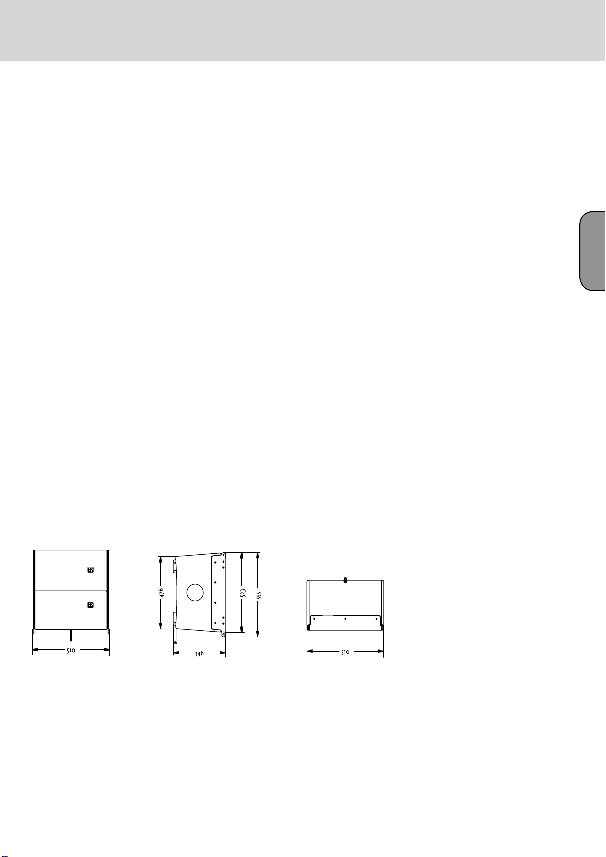
Fig. 2: CTA 208 housing dimensions in mm
English
Page 5
ConTour Array™ 1.0
2. CTA 118 Sub
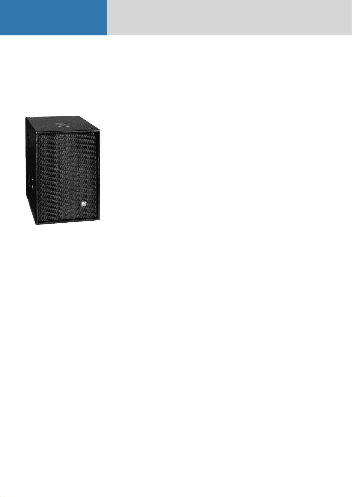
Fig. 3: CTA 118 Sub
Design and Construction
Made of 18-mm 13-ply birch plywood, waterrepellent, black PU lacquer coats the CTA 118
Sub enclosure. A robust metal grille backed with
laminated acoustic foam rubber covers the baffle
board.
The CTA 118 Sub weighs 59 kg. It is 51 cm wide, 73
high and 71 cm deep. Three slot grips routed into
the side panels enable easy transport and set-up; a
recessed handle is on the lid. The active circuitry
resides in a separate chamber at the back of the
enclosure. A removable dolly protects the electronic
components and simplifies transport.
Electrical and Acoustical Data
The CTA 118 Sub enclosure features an 18" woofer.
The CTA 118 Sub enclosure‘s nominal electrical
power-handling is 700 watts RMS at 8 ohms
impedance. It produces 101 dB (1W@1m) sound
pressure, measured under half-space conditions.
Maximum SPL measured under the same conditions
at one meter is 130 dB at 10% THD. The CTA 118
Sub‘s frequency response ranges from 42 Hz to fx
(+/-3 dB). The two integrated PWM power amps
for the subwoofer and the mid/high output deliver
1000W RMS each.
2.1 Specifications, CTA 118 Sub
A professional active subwoofer equipped with a
DDO-Pro™ Controller and a 1000W RMS PWM
power amp, the CTA 118 Sub delivers excellent
impulse response and exceedingly dynamic lowfrequency response. It features an 18" woofer
mounted in a precision-tuned bass reflex enclosure.
Another 1000W RMS PWM power amp drives
HK Audio CTA 208 or ConTour Series™ speakers.
The rectangular block housing is made of 18-mm
birch plywood coated with black PU lacquer. An
impact-resistant steel grille covers the front. A
removabledolly protects the electronic components
and simplifies transport
Its frequency response ranges from the crossover
frequency down to 42 Hz (-3 dB) and 36 Hz (-10 dB).
Maximum SPL under half-space conditions is 130 dB
at 10% THD.
Connectors: 1 Neutrik NL 4 Speakon output, 1 XLR
female, 1 XLR male, 2 Powercon, 2 RJ45 Ethercon
Dimensions (W x H x D): 51 x 73 x 71 cm
Weight: 59 kg
Model: HK Audio CTA 118 Sub
Connections
Ports are out of harm‘s way on a recessed connector
panel on the CTA 118 Sub‘s back. It offers one
Speakon NL 4 connector. Pin assignments are pin
1+ = mid/high +, 1- = mid/high- . A Powercon mains
socket with another Powercon output connects to
the power supply. A female XLR and a male XLR port
serve to route signals. Two Neutrik Ethercon ports
serve to network several CTA 118 Subs.
Page 6

2.2 Technical Data, CTA 118 Sub
Integrated Power Amps:
Output power, Subwoofer: ...........................................1000 W RMS, Class D
Output power, Mid/High: ............................................1000 W RMS, Class D
Protection circuits: .......................................................DDO Pro™ Limiter, thermal protect, short-circuit
Line In/ Through: ........................................................ Female XLR, electronically balanced & floating
Mid/High Out: .............................................................1 Speakon(r) NL 4
Mains In/ Out: .............................................................2 Powercon
Networking/ Communication: .....................................DDO Pro™ Net/RS 485 Ethercon
Woofer: ........................................................................18"
Frequency response - 10 dB: ........................................36 Hz - fx
Frequency response+/- 3 dB: ........................................ 42 Hz - fx
Sensitivity 1W@1m 1): .................................................101 dB
Max. SPL calculated 1): ................................................134 dB 2)
Max. SPL peak 1): .........................................................133 dB
Max. SPL 1): .................................................................130 dB @ 10% THD (50 Hz- 200Hz)
Housing (birch): ..........................................................18 mm (3/4"), 13-ply
Surface coating: ...........................................................Black 2-component PU lacquer
Grille: ...........................................................................Metal grille with black acoustic foam
Handles: ......................................................................6 slot grips routed into the side panels, 1 on the lid
Pole mount: .................................................................M20
Weight: .........................................................................59 kg/ 129.8 lbs.
Dimensions (W x H x D): .............................................51 x 73 x 71 cm, 20" x 28 3/4" x 27 7/8"
Accessories: ................................................................. Protective cover, stack base plate
27
English
1) Measured under half-space conditions 2) Based on peak power handling
Fig. 4: CTA 118 Sub housing dimensions in mm
Page 7

ConTour Array™ 1.0
C. Rigging ConTour Array™ Enclosures
1. Components and Applications of
ConTour Array™ Rigging Hardware
Please also read the Notes on Rigging Safety in Chapter A of this manual.
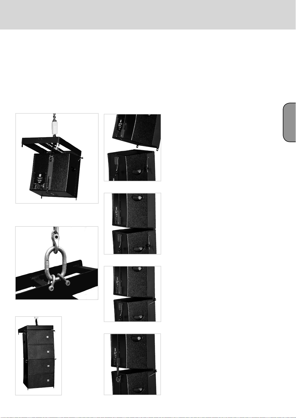
Fig. 5: Integrated rigging attachments
Fig. 6: ConTour Array™ rigging frame
Fig. 7: Shackles for attaching motors, chain hoists
ConTour Array™ rigging hardware consists of the
following parts:
• a rigging frame with two shackles for attaching
motors or chain hoists.
• integrated rigging points on the side and back for
flying ConTour Array™ CTA 208 Mid/High units.
• three quick-release pins per CTA 208 for
connecting the enclosure to the rigging frame.
Important note on pins: Quick-release pins connect
rigging hardware and speaker enclosures, and their
proper function must be tested and verified. Pins
must always engage fully in the (fitted) hole. Under
no circumstances may these pins release on their
own when subjected to tractional forces. The nib in
the center of the pinhead must always be depressed
to insert pins; it releases the ball detents in front.
Once the pin engages in the hole, the nib must ease
back to its initial position.
1.1 Mounting the Rigging Frame
It takes two people to perform these tasks. Remove
the quick-release pins from the enclosure. Set the
rigging frame on the enclosure. First attach the two
front connectors. Turn the rigging frame‘s connector
component down and slide it into the rear rigging
connector.
Insert the rear pin through the hole labeled 0°.
Attach to the rigging frame the shackle that accepts
the motor hook. Your choice of pick point depends
on how sharply you aim to curve the array later.
Tip: If you intend to rig additional enclosures, we
recommend that you attach all the required speaker
cords to the rigging frame now because this task
becomes more difficult as the array grows higher.
Be sure to use cords of sufficient length!
1.2 Setting the DualCurve™ Angle
Curve the two CTA 208 cabinets using the rear
connector component. You have two angles to
choose from, 0° and 9°. Remove the pin on the rear,
insert lead the connector into the rigging track and
secure the connector component with the pin as
pictured.
1.3 Rigging Additional
CTA 208 Mid/High Enclosures
Hoist the mounted CTA 208 Mid/High cabinets to a
height that allows you to roll a second case holding
two enclosures under the array. Remove the two
front pins from the enclosure you wish to mount.
Move the second case with two additional CTA 208s
into position. Slowly lower the top two cabinets
until the two front connectors engage. Insert the
two front pins first, ensuring they engage fully and
securely (see Figure 12 a). You may have to shift
the two enclosures slightly to ease the pins into
position. To attach the rear connector component,
you must swivel it out of the track and ensure it
faces down (see Figure 12 b). Insert the pin through
the hole labeled 0° or 9° as required.
Note: Depending on application, you may not be
able to select a pick point with a shackle. In this
case, use two shackles and a suitable O-ring as
shown in Figure 10.
Check all pins on the top rigging frame to ensure
they seat firmly. Attach the motor to the shackle.
Important: Ensure the motor‘s chain bag hangs
freely and does not rest on the rigging frame!
Engage the motor to lift the cabinet from the case.
Roll the case off to the side. Remove the two front
pins from the enclosure you wish to mount and fold
down its connector component. Now you can rig
further cabinets.
Hoist the array consisting of four CTA 208
enclosures high enough to remove it fully from the
case. Secure the hoisted array against blasts of wind
or unintentional twisting to prevent it from moving.
Page 8
29
English
Fig. 8: Mounting the rigging frame
Fig. 9: Setting an intermediate angle
Fig. 10: Hoisting the mounted CTA 208 enclosure
Fig. 11 a, b, c, d, e: Rigging additional CTA 208 enclosures
Page 9

ConTour Array™ 1.0
2. Groundstacking
3. Mains and Generator
Power Supply
Fig. 12 a, b: ConTour Array™ ground-stack connectors
Depending on application, use two or three
ConTour Array™ subwoofers as the stack‘s base. Set
the desired number of subwoofers on top of one
another.
Caution:
Secure the ground stack to prevent it from tipping!
Use the M10 bushings on the back of the CTA 118
subwoofer and the ground-stack connectors to do
this.
Mount mid/high units individually, one after
another, on the top CTA 118 Sub. Use the ConTour
Array™ stack plate as the base and connector to
the subwoofer. Attach it to the CTA 118 Sub’s pole
mount using the M20 thumb screw. The stack plate
lets you easily adjust mid/high units without having
to move the subwoofer. On this stack plate, you can
freely select the desired down-tilt between 0° and 9°
in 1.5° increments.
Connect no more than two CTA 118 Subs to one
mains phase (16 A). If you use the Powercon Link
port, connect no more than one further CTA 118
Sub. The 13-A limit on maximum input current (see
label) applies to Great Britain because UK power
cables are approved to 13 A only. 16-A current is
permissible in other countries using EU power
cables.
Caution: If you must power the CTA 118 Sub with a
generator, ensure the generator is running before
you switch the system on. Never switch systems
off and on with the help of the generator! This can
damage the PWM power amps’ switching power
supply!
Note: The Powercon Link is not available for 100120-volt units.
Fig. 13: ConTour Array™ stack plate
Fig. 14 a, b: Attaching the stackplate to the CTA 118 Sub
Fig. 15 a,b,c: CTA 208 Mid/High stack
Page 10

D. The ConTour Array™ DDO-Pro™ Controller
1. The DDO-Pro™ Net Port
31
Net Ports link several CTA 118 Subs in a
communication network. Use CAT 5 network cables
or professional Ethercon cables with a metal plug
to do this. Connect the first CTA 118 Sub’s output to
the next unit’s input, and so forth.
Note: This is purely a data interface. The DDO-Pro™
Net Port does not send audio signals.
If you wish to adjust controller settings (for example,
filter, gain or delay), you can do this on any CTA 118
Sub’s control panel. Automatically, the unit becomes
the master controller and sends parameter changes
to all networked CTA 118 Subs (up to 32 units).
Note: It does not send "Utilities" menu settings.
Caution: If you wish to use another CTA 118 Sub
and a ConTour Series™ cabinet (CT 108, CT 112, CT
115) for near-fill or in-fill applications alongside CTA
208 speakers in a larger rig, DO NOT network it!
Otherwise the connected CT 108, CT 112 or CT 115 will
adopt the settings entered for the mid/high array.
2. Audio Signal Routing
3.1 Level
You can adjust input levels from -96 dB to + 6dB in
0.5 dB steps. Use the Up or Down keys to select the
gain setting and confirm your selection with Enter.
Note: The Level parameter adjusts the level after the
analog-to-digital converter to balance out varying
(system) levels. Level does not influence the input
signal’s volume in front of the analog-to-digital
converter. If the display reads “Digital Clip ?! Check
Input !” be sure to reduce the level at the mixing
console. In this case, the signal is saturating the
analog-to-digital converter, distorting the signal’s
rectangular waveform to create square waves. This
sounds extremely annoying and will eventually
destroy the power amp and speakers.
Tip: If you wish to reduce the volume of the lower
mid/high unit in the array – say, because it hangs
low and listeners are close to this unit – you can
use Level to do this. However, Level also affects the
subwoofer’s volume. Increase Sub Level by the same
value to compensate for the difference.
3.2 Key Lock
English
Fig. 16: DDO-Pro™ network
Use an XLR cord to connect the signal source to
the first CTA 118 Sub’s signal input. If you wish to
connect further CTA 118 Subs to the source, do this
using the Signal Through ports. The XLR port’s pin
assignments are: pin 1 = ground, 2=+, 3=-.
Be sure to read section 3.1 covering maximum input
signal level and digital clip error and heed these
guidelines.
3. Handling the
DDO-Pro™ Controller
Four keys operate the device - Menu, Enter, Up and Down.
Menu/ Esc:
This key accesses the controller’s menu structure
and exits a menu level.
Enter:
This key confirm changes and access menu levels.
Up and Down:
These keys navigate within a menu level and
increase and decrease displayed values. Please refer
to the menu structure quick guide at the end of the
chapter to learn more.
3.3 Utilities
Sync Remote
When you confirm the Sync Remote command, the
unit sends the current settings to all networked
controllers. The control panel currently in use is the
master. This feature comes in handy if the network
connection fails.
Noise Reduction
You can activate Noise Reduction on demand. It
mutes signal paths when the rig is off-line. The unit
ships with this feature deactivated.
LCD Contrast
Adjust the display’s contrast to taste using the Up or
Down keys. Confirm your selection with Enter.
Factory Reset
When you confirm this function, ALL settings reset
to their factory defaults. For example, you could use
it to set all delays to 0 ms and levels to 0 dB.
Fig. 17: DDO-Pro™ Controller panel
The AD converter’s Digital Clip indicator
Page 11

ConTour Array™ 1.0
2 x CT108 1 x CT112
Delay Base
Select the preferred delay display reading - meters
(m), feet (ft) or milliseconds (ms). Select the
option with the Up or Down keys and confirm your
selection with Enter.
3.4 Sub Delay
Sub Delay is a time alignment tool, that is, it
compensates differences in mid/high units’ and
subwoofers’ response times. Like Sub Level, Sub
Delay controls subwoofers’ and mid/high units’
relative delay.
For example, if you place subwoofers well in front
of mid/high units, you must delay the subwoofers
accordingly. Do this by adjusting a positive
delay value in the Sub Delay menu. If you place
subwoofers well behind mid/high units, you must
enter negative values to compensate.
Caution: Negative Sub Delay values delay the signal
path from the subwoofer to the mid/high unit,
causing overall system latency! Experience has
shown that this method compensates differences of
15 ms or 5 m without latency problems. The control
range sweeps from -30 ms to 29.6 ms.
3.6 Sub Level
You can adjust the balance of volumes between the
subwoofer and mid/high unit from -12 dB to + 6dB
in 0.5 dB steps. Use the Up or Down keys to select
the Sub Level and confirm your selection with Enter.
3.7 System Setup
A special filter preset is available for each
configuration (see fig. 19 a-f). Be sure to assign
the same preset to each DDO-PRO™ controller for
every configuration (1 to 4 CTA 208s). Use the Up
or Down keys to select the right preset and confirm
your selection with Enter.
1 x CT115 1 x CTA208
4 x CTA208
Fig. 18 a, b, c, d, e, f: System Setups
3.5 Delay
Delay controls the overall delay of a system
comprised of subwoofers and mid/high units. The
highest setting is 72.6 ms.
Page 12

3.8 Quick Guide to the V1.01 Controller’s Menu Structure
33
English
Fig. 19: Menu structure of the DDO-PRO™ Controller
English
Page 13

E. Service
1. Maintenance
35
Regularly check the vents to ensure air flows freely
in and out. Clean the foam rubber filters whenever
necessary. Remove the vent grille on the back to do
this.
2. ConTour Array™
Spare Parts
Note:
• If your equipment needs service, please turn to
your HK Audio dealer or the HK Audio distributor in
your country. They stock the required spare parts.
• In the event of a defect, always indicate the
defective device’s serial number. This way the HK
Audio service team can immediately find out if an
update is available for your product.
• Use only original HK Audio replacement speakers
and parts! Most were developed especially for HK
Audio products and are not available direct from
speaker manufacturers!
3. Replacing Loudspeakers
and Voice Coils
3.1 1", 8" and 18" Speakers
Proceed as follows to replace the given speaker:
• Unfasten and remove the Phillips screws holding
the grille in place. Remove the grille. These screws
are on the CT 118 Sub’s front panel and the CTA
208’s side and bottom panels.
• Unfasten and remove the hex head bolts holding
the speaker in place.
• The speaker is now detached. Disconnect the
speaker wires.
3.2 The Drivers’ Voice Coils
Proceed as follows to replace the drivers’ voice coils:
• Remove the front grille as described above.
• Unfasten the four screws holding the horn yoke
and remove the horn and driver from the baffle.
Disconnect the wires connecting the driver. Ensure
correct polarity when installing and connecting
a replacement speaker! Red= positive, black =
negative
• Unfasten the voice coil housing’s hex head bolts
using a 3-mm wrench.
• Take the lid off the voice coil housing.
• Replace the voice coil.
Important note: Replace the voice coil in a clean
working environment only. Be sure to keep dust
and dirt out of the open driver. If despite your
precautions particles manage to get in, use a strip
of adhesive tape to remove them or carefully blow
compressed air into the back of the driver to whisk
the particles out. When installing the new voice
coil, ensure it is centered properly. Proceed as
follows to check this:
Close the cover of the voice coil housing and
reconnect the cords (red = positive, black =
negative). Feed a sine wave signal with a frequency
between 1000 Hz and 1500 Hz into the mid/high
enclosure’s input. Sweep through the frequency.
If you hear abrasive noises like crackling or
scratching, the voice coil is not centered properly.
Reopen the voice coil chassis and turn the voice coil
a bit until it renders the signal cleanly!
4. Checking Speakers’ Phase
As a precaution, always check the components’
phase using a suitable phase-checker after replacing
speakers. To do this, connect the CTA 208 mid/high
unit to the CTA 118 Sub using a Speakon cord.
Note: If you are checking the CTA 208 mid/high
unit in passive mode with an external power amp,
you will get a different phase reading! Therefore
always use the CTA 118 Sub for phase checks.
Connect the phase-checker to the CTA 118’s signal
input. It may be advisable to lower the input level on
the DDO-Pro™ Controller!
The speakers’ phases should read as follows:
With CTA 118 Sub:
18" woofer: In phase (+)
8" speaker: Out of phase (-)
1" driver: In phase (+)
CTA 208 passive:
8" speaker: In phase (+)
1" driver: Out of phase (-)
English
Caution: When installing and connecting a
replacement speaker, ensure the polarity is correct!
Red= positive, black = negative
Page 14

DRAWING-NUMBERS
EXAMPLE
HK0106-EX-R01-1A
VERSION
SERIAL NUMBER
DEPARTMENT:
R = R&D
REVISION
PROJECT-NR.:
HK = HK AUDIO
HU = HUGHES&KETTNER
MP = MINDPRINT
CHARACTER:
BL = SHEET METAL / BLECH
EX = EXPLODED DRAWING / EXPLOSIONSZEICHNUNG
HZ = CABINET / HOLZGEHÄUSE
KU = PLASTIC / KUNSTSTOFF
LP = PCB / LEITERPLATTEN
SO = MISCELLANEOUS / SONSTIGES
SP = SCHEMATIC / SCHALTPLÄNE
TR = TRANSFORMER / TRANSFORMATOR
GK = WIRING DIAGRAM / GERÄTEVERKABELUNG
Page 15

Stand
W
Y
r
Standard for single wire confection.
16 B 150 638 I - 485 W Z I 1015
style 1015 according UL specifications
I = completely insulated with black shrinktube or appropriate sleeve
IT = partly insulated; only crimp connection insulated.
no marking = without insulation
Z = with additional junction
no marking = without additional junction
W = angled faston
no marking = straight faston
17. Jun 04
Faston connector brass tin-plated DIN 46245
638 = 6,3 * 0,8 [mm]
488 = 4,8 * 0,8 [mm]
485 = 4,8 * 0,5 [mm] if fully insulated (I) insulation with blue shrinktube
if partly insulated (IT) use IF 602 485 .
288 = 2,8 * 0,8 [mm]
285 = 2,8 * 0,5 [mm] if fully insulated (I) insulation with blue shrinktube
if partly insulated (IT) use IF 602 485
abiso = 5mm bared and tin-plated (teilabzug)
text for special constructions, (for example. 4mm ringshaped faston)
the larger faston connector always mentioned at first. (Nathan drawing number controlling)
lenght in mm within a 50 mm raster
colour
B = black (phase conductor)
R = red
BR = brown
BL = blue (neutral conductor)
= white
G = yellow-green (ground bonding/ earthing connection)
cross section
16 = AWG 16 (prefered usage)
Q1.5 = H07VK 1,5mm² (prefered usage)
wire designation:
P + lfd Nr. = AWG single wire black, red, blue, brown or white
E + lfd Nr. = AWG single wire green- yellow
L + lfd N
FQL + lfd Nr. = crossover wiring H07VK
Regarding special wirings like wiring harness or similar, drawings will be prepared and appropriate
. = twisted AWG double wire, lenght specification always in twisted condition
drawing numbers will be stored in the article archive.
Page 16

Confidential, for authorized service technicians only! Do not disclose
this information to or share these documents with third parties.
TECHNICAL SERVICE:
Stamer Musikanlagen GmbH • Magdeburger Str. 8 • 66606 St.Wendel • Germany
Music & Sales P.E. GmbH • Leipziger Str. 3 • 66606 St.Wendel • Germany
Service Documents
HK1805
CTA
CTA 118 SUB
SUBWOOFER
Page 17

2 E 400280
10E 974220
17E 976115
HK1805-HZ-R02-1D
13 E 974501
16E 976094
4 E 970760
18
8 E 974145
15 E 976010
7 E 974020
11
3 E 502198
HK1805-EX-R03-1D
19E 976162
1E 1134
HK1805-EX-R02-1B
11E 974232
18 E 976159
4
12E 974272
ÄNDERUNG
INDEX
drawing-nr. update C. Loris
1B-240506
ZEICHNER
13
5 E 972008
HK1805-SO-R04-1A
14 E 976009
9 E 974218
TITEL:
6E 974012
66606 St. Wendel / Germany
22 E 994199
ZEICHNUNGS-NR.:
ERSTELLT VON:
GEPRÜFT/
FREIGEGEBEN VON:
WERKSTOFF:
DATEINAME:
HK1805-EX-R04-1B
C. LORIS 1
HK1805-EX-R04-1B-Bass-gesamt
HK1805-SUB COMPLETE
EXPLODED DRAWING
OBERFLÄCHE:
VERSION:
AM:
24.05.2006
AM:
/
REVISION:
BLATT:
2
B1
BLÄTTER
Page 18

Pos. part-no. 1 description Beschreibung quantity
1 1134 HK1805-bass front grill assembly HK1805-Frontgitterbaugruppe Bass 1
2 400280 HK1805-bass cabinet HK1805-Bass Holzgehäuse 1
3 502198 Electronic-Chassis HK1805-Elektronikchassis 1
4 970760 plate for butterfly lock CT 118 Blech Schliessplatte CT118 2
5 972008 damping wool Dämmwolle Hochbauschvlies 1
6 974012 hexagon socket head cap screw, M6x30, black Inbusschraube M6*30 sw 8
7 974020 hexagon socket head cap screw, M5x20, black Inbusschraube M5x20sw 17
8 974145 ABC-Spax-S chipboard screw, panhead Z, 5x25, black Pan Head-Z ABC-Spax sw 5*25 4
9 974218 ABC-Spax-S chipboard screw, panhead Z, 5x20, black Pan Head-Z ABC-Spax sw 5*20 4
10 974220 hexagon socket countersunk head screw, M6x40, black Inbussenkschraube M6x40 sw 4
11 974232 ABC-Spax-S chipboard screw, panhead Z, 3.5x12, zinc plated Pan Head-Z ABC-Spax vz 3,5*12 12
12 974272 cross recessed raised countersunk screw, M5x10, black Linsensenkschraube M5*10 sw 4
13 974501 hexagon socket countersunk head screw, M4x16, black Inbussenkschraube M4x16 sw 4
14 976009 rubber foot D38*H11 [mm] Gummifuss D38*H11 [mm] 4
15 976010 rubber foot D38*H20 [mm] Gummifuss D38*H20 [mm] 4
16 976094 plastic dish 3403 HKBS! DART ! Griffschale 3403 HKBS! DART ! 1
17 976115 connector plate Befestigungsplatte M20 1
18 976159 plastic dish Premium One Griffinnenschale Premium One 6
19 976162 rubberbuffer d=18 h=40mm Gummipuffer d=18 h=40 Typ B 4
20* 982037 sealing tape 2x6mm Iso-Zell-Band fadenvers. 2*6mm 0,54 lfdm
21* 982044 sealing tape 2x15mm Iso-Zell-Band fadenvers. 2*15mm 3,70 lfdm
22 994199 SICA LP 470.100_3300WT 8 Ohm SICA LP 470.100_3300WT 8 Ohm 1
ÄNDERUNG
INDEX
drawing-nr. update C. Loris
1B-240506
ZEICHNER
66606 St. Wendel / Germany
ZEICHNUNGS-NR.:
ERSTELLT VON:
GEPRÜFT/
FREIGEGEBEN VON:
WERKSTOFF:
DATEINAME:
HK1805-EX-R04-1B
C. LORIS 2
HK1805-EX-R04-1B-Bass-gesamt
TITEL:
HK1805-SUB COMPLETE
EXPLODED DRAWING
VERSION:
AM:
AM:
OBERFLÄCHE:
24.05.2006
/
REVISION:
BLATT:
2
B1
BLÄTTER
Page 19

Pos. part-no. 1 description Beschreibung quantity
1 970815 HK1805-bass front grid HK1805-Frontgitter-Bass 1
2 972086 acoustics foam anthracite 5mm Akustikschaum Anthrazit 5mm 1
3 980251 logo 'hk'ConTourSer. 35x35x3mm Logo 'hk'ConTourSer. 35x35x3mm 1
ÄNDERUNG
INDEX
1B-240506 PPI 15, drawing-nr. update C. Loris
ZEICHNER
2 E 972086
HK1805-SO-R02-1B
TITEL:
3E 980251
1 E 970815
HK1805-BL-R24-1C
66606 St. Wendel / Germany
ZEICHNUNGS-NR.:
ERSTELLT VON:
GEPRÜFT/
FREIGEGEBEN VON:
WERKSTOFF:
DATEINAME:
HK1805-EX-R02-1B
C. Loris 1
HK1805-EX-R02-1B-FRONTGITTER-BASS
HK1805-BASS-FRONT GRILLE
EXPLODED DRAWING
OBERFLÄCHE:
VERSION:
AM:
24.05.2006
AM:
/
REVISION:
BLATT:
1
B1
BLÄTTER
Page 20

17E 974102
27E 976135
19
13E 970814
HK1805-BL-R28-1A
1E 547058
5E 931304
5
10 E 970811
HK1805-BL-R26-1E
18 E 974103
3E 600090
HK1805-LP-R03-1A
19
27
21 E 974290
23E 974392
20E 974157
25E 974521
25
ÄNDERUNG
INDEX
1B-240506 drawing-nr. update C. Loris
1C-300506 replacement of cables
1D-120906 assembly revised
ZEICHNER
F. Sitter
F. Sitter
12E 970813
HK1805-BL-R13-1D
2E 600090
HK1805-LP-R04-1A
16E 974051
14E 972009
HK1805-SO-R01-1B
15 E 972041
9 E 959052
11E 970812
HK1805-BL-R27-1A
28 E 976141
19
4 E 600091
22 E 974362
19 E 974110
6E 952141
8E 952305
16
14
24E 974444
11
23
26 E 976007
7E 952153
66606 St. Wendel / Germany
ZEICHNUNGS-NR.:
ERSTELLT VON:
GEPRÜFT/
FREIGEGEBEN VON:
WERKSTOFF:
DATEINAME:
TITEL:
HK1805-BASS-CHASSIS
EXPLODED DRAWING
HK1805-EX-R03-1D
C. LORIS 1
HK1805-EX-R03-1D-CHASSIS
OBERFLÄCHE:
VERSION:
AM:
12.09.2006
AM:
/
REVISION:
BLATT:
4
BLÄTTER
D1
Page 21

Pos. part-Nor. 1 description Beschreibung quantity
1 547058 mainboard PCB complete Mainboardplatine fertigbestückt 1
2 600090 Networkinterfaceboard is part of Inputboard Interfaceplatine als Teil von Inputplatine 1
3 600090 Inputboard 54_Inputplatine fertigbestückt 1
4 600091 mains filter assembly 220-240V 60 Netzfilter CTA 118 220-240V 1
5 931304 ferrite teroid core, 25x15x12 Ferritring, geschlossen 25x15x12 3
6 952141 mains inlet PowerCon Netzbuchse Power Con Inlet 1
7 952153 mains outlet PowerCon Netzbuchse Power Con Outlet 1
8 952305 speakon chassis connector, NL4MP-3 Speakonbuchse 4pol eckig, NL4MP-3 1
9 959052 PWM amp module 100-240V PWM Endstufe 100-240Volt 2
10 970811 HK1805 air guide HK1805_Lüftungshaube_PWM 2
11 970812 HK1805 ventilation grill HK1805_Lüftungsgitter 2
12 970813 HK1805 sheet metal chassis HK1805_Blechchassis 1
13 970814 ribbon connector safety lock HK1805_Pfostensteckverbinder-Schutzblech 1
14 972009 acoustic foam anthracite 5mm, PPI20 Akustikschaum Anthrazit 5mm, PPI20 2
15 972041 rubber punching 25x25x15mm Zellkaut. -Stanzteil 25x25x15mm 1
16 974051 plastic PCB spacer, 4.2x8x5, Polyamid black Dist.Hülse PE 4,2*8*5 [mm] 12
17 974102 hexagon nut, class 8, M3, zinc plated Sechskantmutter M3 vz 2
18 974103 toothed lock washer, D=4.3, AZ, zinc plated Fächer-Scheibe az, 4,3 vz 2
19 974110 self locking hexagon nut with plastic insert, M3, zinc plated Stopmutter M3 vz 19
20 974157 cross recessed raised countersunk tapping screw, 2.9x9.5, black Blechschr. Senk-Li 2,9*9,5 sw 4
21 974290 self locking hexagon nut with plastic insert, M4, zinc plated Stopmutter M4 vz 8
22 974362 hexagon PCB spacer, type B, M3x12, zinc plated Dist. Bol Innen/Außengew. M3*12 vz 3
23 974392 hexagon socket oval head screw, M3x8, black Linsenschr.m.Innens. M3*8 sw 12
24 974444 cross recessed raised countersunk screw, M3x12, black Linsensenkschraube M3*12 sw 4
25 974521 cross rec. raised counters. tap. screw w. cutting slot, 2.9x9.5, black Senkschr. f. Kunststoff 2,9*9,5, sw 6
26 976007 cable tie 2,5x100 (mm) Kabelbinder natur 2,5x100 (mm) 14
27 976135 socket for cable tie Schraubsockel 5
28 976141 rubberbuffer 15x15 B Gummipuffer GM-Puffer 15x15 B 8
29* 982044 sealing tape 2x15mm Iso-Zell-Band fadenvers. 2*15mm 0,20 lfdm
30* 986019 adhesive tape, double-sided, clear Kleebeband, doppelseitig, klar 0,20 lfdm
ÄNDERUNG
INDEX
1B-240506 drawing-nr. update C. Loris
1C-300506 replacement of cables
1D-120906 assembly revised
ZEICHNER
F. Sitter
F. Sitter
66606 St. Wendel / Germany
ZEICHNUNGS-NR.:
ERSTELLT VON:
GEPRÜFT/
FREIGEGEBEN VON:
WERKSTOFF:
DATEINAME:
HK1805-EX-R03-1D
C. LORIS 2
HK1805-EX-R03-1D-CHASSIS
TITEL:
HK1805-BASS-CHASSIS
EXPLODED DRAWING
AM:
AM:
OBERFLÄCHE:
VERSION:
12.09.2006
/
REVISION:
BLATT:
4
D1
BLÄTTER
Page 22

9
2
4
1
ÄNDERUNG
INDEX
1B-240506 drawing-nr. update C. Loris
1C-300506 replacement of cables
1D-120906 assembly revised
ZEICHNER
F. Sitter
F. Sitter
3
9
TITEL:
HK1805-BASS-CHASSIS
66606 St. Wendel / Germany
ZEICHNUNGS-NR.:
ERSTELLT VON:
GEPRÜFT/
FREIGEGEBEN VON:
WERKSTOFF:
DATEINAME:
HK1805-EX-R03-1D
C. LORIS 3
HK1805-EX-R03-1D-CHASSIS
EXPLODED DRAWING
OBERFLÄCHE:
VERSION:
AM:
12.09.2006
AM:
/
REVISION:
BLATT:
4
D1
BLÄTTER
Page 23

E 962346, stranded wire P 42
AWG14/16 Style 1015
HK0502-KA-R04-XX
E 964052, powercable DIVA
Y-stranded wire
HK1805-KA-R01-XX
E 962288, stranded wire E3
16-YG-200-638-485 1015, AWG
962314 stranded wire E18
16-YG-200-638-eyelet, AWG
E 962038, stranded wire E4
16-YG-120-638-638 1015, AWG
E 962054, stranded wire 2*JST 3pol,
140mm AWG 26 Style 1007
E 965618, flat ribbon cable 20-2-360mm , Typ 6
AWG 28 flexible grey RM1,27
ÄNDERUNG
INDEX
1B-240506 drawing-nr. update C. Loris
1C-300506 replacement of cables
1D-120906 assembly revised
ZEICHNER
F. Sitter
F. Sitter
E 962262, stranded wire FQL17
Q1.5-R-1000-488I-bared
E 962263, stranded wire FQL17
Q1.5-B-1000-488I-bared
E 962337, stranded wire P39
CABLING 230V
Pos. part-no. 1 part-no. 2 part-no. 3 description Beschreibung quantity
1 962038 str anded wi re E4 16-YG-120-638-638 1015, A WG Litze E 4 16-YG-120-638- 638 1015, AWG 3
2 962054 s tranded w ire 2xJST 3pol, 140mm AW G26 Style 1007 Litze 2xJST 3pol, 140mm A WG26 Styl e 1007 2
3 962262 s tranded w ire FQL17 Q1.5- R-1000-488I- bared Litze FQL17 Q1.5-R- 1000-488I-bared 1
4 962263 s tranded w ire FQL17 Q1.5- B- 1000-488I-bar ed Litze FQL17 Q1.5-B-1000-488I-bared 1
5 962288 stranded wire E3 16-YG-200- 638-485 1015, A WG Litze E 3 16-YG-200-638-485 1015, A WG 2
6 962314 stra nded wir e E18 16-Y G-200-638- eyelet, AW G stranded wi re E18 16- YG-200- 638-eyelet, AW G 2
7 962337 strande d w ir e P39 16-R-600- 488I-485IT 1015, AW G Litze P39 16-R-600-488I-485IT 1 015, AW G 1
8 962338 stranded wir e P39 16-B-600-488I-485I 1015, AWG Litz e P39 16-B-600-488I-485I 1015, AW G 1
9 962346 (230V) stranded wir e P42 AWG14/16 Style 1015 HK0502-KA- R04-xx Litze P42 AW G14/16 Style 1015 HK0502-KA- R04-xx 2
10 964052 powerca ble DIVA, Y-s tranded w ire HK1805- KA-R01 -xx Powerkabe l DIVA, Y -Litze HK1805-KA- R01-xx 1
11 965618 f lat ri bbon cabl e 20-2-360, Typ 6, AWG 28 F lachbandkabel 20- 2-360, Typ 6, A WG 28 1
12 965626 fla t ribbon c able 20-2-200, Typ 5, AWG 28 Flac hbandka bel 20-2-200, Typ 5, AW G 28 1
16-R-600-488I-485IT 1015, AWG
E 962338, stranded wire P39
16-B-600-488I-485I 1015
66606 St. Wendel / Germany
ZEICHNUNGS-NR.:
ERSTELLT VON:
GEPRÜFT/
FREIGEGEBEN VON:
WERKSTOFF:
DATEINAME:
HK1805-EX-R03-1D
C. LORIS 4
HK1805-EX-R03-1D-CHASSIS
E 965626, flat ribbon cable 20-2-200mm Typ 5,
AWG 28 flexible grey RM1,27
E 962054, stranded wire 2*JST 3pol,
140mm AWG 26 Style 1007
E 962038, stranded wire E4
16-YG-120-638-638 1015, AWG
TITEL:
HK1805-BASS-CHASSIS
EXPLODED DRAWING
OBERFLÄCHE:
VERSION:
AM:
12.09.2006
AM:
/
REVISION:
BLATT:
4
D1
BLÄTTER
Page 24

pos. part-no. 1 description Beschreibung quantity
1 547058 ConTour CTA 118 Mainboard ConTour CTA 118 Mainboard 1
2 966010 push-bottom cylindric, black Knopf-Taster rund/zyl. schwarz 1
3 966046 plunger type key top, 9*9, B32-1210 Knopf-Taster 9*9 B32-1210 4
4 970800 plexiglas CTA Operating panel Plexiglas CTA Operating panel 1
5 974110 self locking hexagon nut with plastic insert, M3, zinc plated Stopmutter M3 vz 4
6 974212 hexagon PCB spacer, type B, M3x15, zinc plated Dist. Bol Innen/Außengew. M3*15 vz 4
7E 974221
7 974221 hexagon socket countersunk head screw, M3x8, zinc plated Inbussenkschraube M3x8 vz 4
4E 970800
6E 974212
INDEX CHANGES
2E 966010
3 E 966046
1E 547058
TITLE:
HK1805-CTA DISPLAY
5E 974110
RESP.
66606 St. Wendel / Germany
DRAWING-NO.:
DRAWN BY:
CHECKED BY:
MATERIAL:
FILENAME:
HK1805-EX-R11-1A
C. LORIS 1
HK1805-EX-R11-1A-DISPLAY
EXPLODED DRAWING
VERSION:
DATE:
12.09.2006
DATE:
FINISH:
REVISION:
PAGE:
A1
PAGES
Page 25

2
3
5
1
6
2
9
4
INDEX CHANGES
RESP.
9
7 9
Spa re Parts List for: HK1805-NZ-R01-1C
Project: CTA
Project Number: HK1805
As sembly: Mainboard
pos. part no. de scription Bezeichnung refe rence de signators quantity
1 936010 LED 5mm grün s tandard dif fused LED 5mm grün Standard dif fused LD3, LD2 2
2 936041 LED 5mm blau semi diff used LED 5mm blau semi diff used LD1, LD10-12, LD6-9, LD13-14 10
3 936046 LED 5mm orange, s tandard LED 5mm orange, Standar d LD5, LD4 2
4 946009 NAIS TQ2-12V DC print, miniature relais Relais NAIS TQ2-12V DC print REL1 1
5 950021 tac tile push button B3F-4055 Taster Tac-Sw itch B3F-4055 SW4, SW3, SW2, SW1 4
6 950083 pus h button sw itch, v ertical, 2x UM (2 Pols) Drucks chalter ohne LED 11,25mm SW5 1
7 952021 con nector SEK18 2*8pol Wannenstec ker 2*8pol Gprint JP13 1
8 952053 JST, 3-pol, vert ., print, B 3B-EH-A Stif tleiste JST 3pol Gprint JP3, JP1 2
9 952150 con nector SEK18 2*10pol. Wannenst ecker 2*10pol Gprint JP6, JP5 2
66606 St. Wendel / Germany
DRAWING-NO.:
DRAWN BY:
CHECKED BY:
MATERIAL:
FILENAME:
HK1805-LP-R01-1C
C. LORIS 1
HK1805-LP-R01-1C-MAINBOARD
TITLE:
HK1805-CTA
MAINBOARD
FINISH:
VERSION:
DATE:
DATE:
12.10.2006
REVISION:
PAGE:
A1
PAGES
Page 26

E 959052
PWM Amp Module 100-240V
To ensure the procedure of our quality assurance
(burn-in-test, quality-test,...) please send the complete
module to our technical service for replacement.
For customer inquiry please contact our service-team.
Page 27

Pos. part-no. 1 description Beschreibung quantity
1 400282 finished board fertiges Rollbrett aus Schreinerei 1
2 974099 Mechanical locking screw, TENSILOCK W151, M6x20 Sperrzahnschraube M 6*20 vz, Tensilock W151 16
3 974225 cross recessed panhead screw, M4x10, zinc plated Linsenschraube M4 x 10 vz 10
4 976143 Butterfly 170290 Butterfly 170290 2
5 976158 castor 100mm, blue Lenkrolle 100mm, blau 4
2 E 974099
5 E 976158
INDEX
ÄNDERUNG
ZEICHNER
3E 974225
4E 976143
1E 400282
HK1805-HZ-R04-1A
TITEL:
HK1805 CTA DOLLY
66606 St. Wendel / Germany
ZEICHNUNGS-NR.:
ERSTELLT VON:
GEPRÜFT/
FREIGEGEBEN VON:
WERKSTOFF:
DATEINAME:
HK1805-EX-R01-1A
C. LORIS 1
HK1805-EX-R01-1A-ROLLBRETT
EXPLODED DRAWING
OBERFLÄCHE:
VERSION:
AM:
15.03.2006
AM:
/
REVISION:
BLATT:
1
A1
BLÄTTER
Page 28

8 E 974114
16 E 976010
15 E 976009
12 E 974524
7 E 974091
18E 976157
2E 970828
4E 970830
1E 598005
9
5 E 970831
INDEX
ÄNDERUNG
13
7
ZEICHNER
2
9
9
12
18
3 E 970829
11
12
9 E 974168
11E 974453
13 E 974525
7
11
14 E 974526
17 E 976106
TITEL:
HK1805-CTA-STACKING PLATE
EXPLODED DRAWING
66606 St. Wendel / Germany
ZEICHNUNGS-NR.:
10E 974320
6E 970842
ERSTELLT VON:
GEPRÜFT/
FREIGEGEBEN VON:
WERKSTOFF:
DATEINAME:
HK1805-EX-R10-1A
C. LORIS 1
HK1805-EX-R10-1A-Groundstack
OBERFLÄCHE:
VERSION:
AM:
15.05.2006
AM:
N/A
REVISION:
BLATT:
2
A1
BLÄTTER
Page 29

Pos. part-no. 1 description Beschreibung quantity
1 598005 spare tightening knob M20 Gewinde mit Anschlag M20 1
2 970828 HK1805-groundstack front block HK1805-Groundstack Frontklotz 2
3 970829 HK1805-groundstack mounting plate HK1805-Groundstack Montageplatte 1
4 970830 HK1805-groundstack left mounting part HK1805-Groundstack Halterung links 1
5 970831 HK1805-groundstack right mounting part HK1805-Groundstack Halterung rechts 1
6 970842 sheet metal CTA subwoofer-connector Blech CTA Bass-Verbinder 2
7 974091 toothed lock washer, D=5.3, AZ, zinc plated Fächer-Scheibe az, 5,3 vz 6
8 974114 self locking hexagon nut with plastic insert, M5, zinc plated Stopmutter M5 vz 2
9 974168 washer, form A, 5.3*12, zinc plated Unterleg-Scheibe 5,3*12 vz 6
10 974320 cross recessed countersunk screw, M5x30, zinc plated Senkschrauben M5*30 vz 2
11 974453 hexagon socket countersunk head screw, M5x16, black Inbussenkschraube M5x16 sw 5
12 974524 hexagon domed cap nut, M5, zinc platec Hutmutter M5 vz 6
13 974525 hexagon socket head cap screw, M5x14, black Inbusschraube M 5x14 sw 2
14 974526 hexagon socket countersunk head screw, M5x12, black Inbussenkschraube M 5x12 sw 3
15 976009 rubber foot D38*H11 [mm] Gummifuss D38*H11 [mm] 2
16 976010 rubber foot D38*H20 [mm] Gummifuss D38*H20 [mm] 2
17 976106 spare tightening knob Molpen M10x27mm Knopfschraube Molpen M10x27mm 4
18 976157 self locking clamping pin KSB2234 8x17 Kugelsperrbolzen KSB2234 8x17 2
INDEX
ÄNDERUNG
ZEICHNER
66606 St. Wendel / Germany
ZEICHNUNGS-NR.:
ERSTELLT VON:
GEPRÜFT/
FREIGEGEBEN VON:
WERKSTOFF:
DATEINAME:
HK1805-EX-R10-1A
C. LORIS 2
HK1805-EX-R10-1A-Groundstack
TITEL:
HK1805-CTA-STACKING PLATE
EXPLODED DRAWING
VERSION:
AM:
15.05.2006
AM:
OBERFLÄCHE:
N/A
REVISION:
BLATT:
2
A1
BLÄTTER
Page 30

HK1805-EX-R04-1B-SUB-COMPLETE
G
x
Article No. 1 (230V) Article No. 2 (117V) Article No. 3 (100V) Description Bezeichnung Quantity
1134 HK1805-bass front grill assembly HK1805-Frontgitterbaugruppe Bass 1
400280 HK1805-bass cabinet HK1805-Bass Holzgehäuse 1
502198 Electronic-Chassis HK1805-Elektronikchassis 1
970760 plate for butterfly lock CT 118 Blech Schliessplatte CT118 2
972008 damping wool Dämmwolle Hochbauschvlies 1
974012 hexagon socket head cap screw, M6x30, black Inbusschraube M6*30 sw 8
974020 hexagon socket head cap screw, M5x20, black Inbusschraube M5x20sw 17
974145 ABC-Spax-S chipboard screw, panhead Z, 5x25, black Pan Head-Z ABC-Spax sw 5*25 4
974218 ABC-Spax-S chipboard screw, panhead Z, 5x20, black Pan Head-Z ABC-Spax sw 5*20 4
974220 hexagon socket countersunk head screw, M6x40, black Inbussenkschraube M6x40 sw 4
974232 ABC-Spax-S chipboard screw, panhead Z, 3.5x12, zinc plated Pan Head-Z ABC-Spax vz 3,5*12 12
974272 cross recessed raised countersunk screw, M5x10, black Linsensenkschraube M5*10 sw 4
974501 hexagon socket countersunk head screw, M4x16, black Inbussenkschraube M4x16 sw 4
976009 rubber foot D38*H11 [mm] Gummifuss D38*H11 [mm] 4
976010 rubber foot D38*H20 [mm] Gummifuss D38*H20 [mm] 4
976094 plastic dish 3403 HKBS! DART ! Griffschale 3403 HKBS! DART ! 1
976115 connector plate Befestigungsplatte M20 1
976159 plastic dish Premium One Griffinnenschale Premium One 6
976162 rubberbuffer d=18 h=40mm Gummipuffer d=18 h=40 Typ B 4
982037 sealing tape 2x6mm Iso-Zell-Band fadenvers. 2*6mm 0,54 lfdm
982044 sealing tape 2x15mm Iso-Zell-Band fadenvers. 2*15mm 3,70 lfdm
994199 SICA LP 470.100_3300WT 8 Ohm SICA LP 470.100_3300WT 8 Ohm 1
HK1805-EX-R02-1B-SUB-FRONTGRILLE-ASSEMBLY
Article No. 1 (230V) Article No. 2 (117V) Article No. 3 (100V) Description Bezeichnung Quantity
970815 HK1805-bass front grid HK1805-Frontgitter-Bass 1
972086 acoustics foam anthracite 5mm Akustikschaum Anthrazit 5mm 1
980251 logo 'hk'ConTourSer. 35x35x3mm Logo 'hk'ConTourSer. 35x35x3mm 1
HK1805-EX-R03-1D-CHASSIS/CABLIN
Article No. 1 (230V) Article No. 2 (117V) Article No. 3 (100V) Description Bezeichnung Quantity
547058 mainboard PCB complete Mainboardplatine fertigbestückt 1
600090 Networkinterfaceboard is part of Inputboard Interfaceplatine als Teil von Inputplatine 1
600090 Inputboard 54_Inputplatine fertigbestückt 1
600091 mains filter assembly 220-240V 60 Netzfilter CTA 118 220-240V 1
931304 ferrite teroid core, 25x15x12 Ferritring, geschlossen 25x15x12 3
952141 mains inlet PowerCon Netzbuchse Power Con Inlet 1
952153 mains outlet PowerCon Netzbuchse Power Con Outlet 1
952305 speakon chassis connector, NL4MP-3 Speakonbuchse 4pol eckig, NL4MP-3 1
959052 PWM amp module 100-240V PWM Endstufe 100-240Volt 2
962038 stranded wire E4 16-YG-120-638-638 1015, AWG Litze E4 16-YG-120-638-638 1015, AWG 3
962054 stranded wire 2xJST 3pol, 140mm AWG26 Style 1007 Litze 2xJST 3pol, 140mm AWG26 Style 1007 2
962262 stranded wire FQL17 Q1.5-R-1000-488I-bared Litze FQL17 Q1.5-R-1000-488I-bared 1
962263 stranded wire FQL17 Q1.5-B-1000-488I-bared Litze FQL17 Q1.5-B-1000-488I-bared 1
962288 stranded wire E3 16-YG-200-638-485 1015, AWG Litze E3 16-YG-200-638-485 1015, AWG 2
962314 stranded wire E18 16-YG-200-638-eyelet, AWG stranded wire E18 16-YG-200-638-eyelet, AWG 2
962337 stranded wire P39 16-R-600-488I-485IT 1015, AWG Litze P39 16-R-600-488I-485IT 1015, AWG 1
962338 stranded wire P39 16-B-600-488I-485I 1015, AWG Litze P39 16-B-600-488I-485I 1015, AWG 1
962346 stranded wire P42 AWG14/16 Style 1015 HK0502-KA-R04-xx Litze P42 AWG14/16 Style 1015 HK0502-KA-R04-x
2
Page 31

964052 powercable DIVA, Y-stranded wire HK1805-KA-R01-xx Powerkabel DIVA, Y-Litze HK1805-KA-R01-xx 1
Y
965618 flat ribbon cable 20-2-360, Typ 6, AWG 28 Flachbandkabel 20-2-360, Typ 6, AWG 28 1
965626 flat ribbon cable 20-2-200, Typ 5, AWG 28 Flachbandkabel 20-2-200, Typ 5, AWG 28 1
970811 HK1805 air guide HK1805_Lüftungshaube_PWM 2
970812 HK1805 ventilation grill HK1805_Lüftungsgitter 2
970813 HK1805 sheet metal chassis HK1805_Blechchassis 1
970814 ribbon connector safety lock HK1805_Pfostensteckverbinder-Schutzblech 1
972009 acoustic foam anthracite 5mm, PPI20 Akustikschaum Anthrazit 5mm, PPI20 2
972041 rubber punching 25x25x15mm Zellkaut. -Stanzteil 25x25x15mm 1
974051 plastic PCB spacer, 4.2x8x5, Polyamid black Dist.Hülse PE 4,2*8*5 [mm] 12
974102 hexagon nut, class 8, M3, zinc plated Sechskantmutter M3 vz 2
974103 toothed lock washer, D=4.3, AZ, zinc plated Fächer-Scheibe az, 4,3 vz 2
974110 self locking hexagon nut with plastic insert, M3, zinc plated Stopmutter M3 vz 19
974157 cross recessed raised countersunk tapping screw, 2.9x9.5, black Blechschr. Senk-Li 2,9*9,5 sw 4
974290 self locking hexagon nut with plastic insert, M4, zinc plated Stopmutter M4 vz 8
974362 hexagon PCB spacer, type B, M3x12, zinc plated Dist. Bol Innen/Außengew. M3*12 vz 3
974392 hexagon socket oval head screw, M3x8, black Linsenschr.m.Innens. M3*8 sw 12
974444 cross recessed raised countersunk screw, M3x12, black Linsensenkschraube M3*12 sw 4
974521 cross rec. raised counters. tap. screw w. cutting slot, 2.9x9.5, black Senkschr. f. Kunststoff 2,9*9,5, sw 6
976007 cable tie 2,5x100 (mm) Kabelbinder natur 2,5x100 (mm) 14
976135 socket for cable tie Schraubsockel 5
976141 rubberbuffer 15x15 B Gummipuffer GM-Puffer 15x15 B 8
982044 sealing tape 2x15mm Iso-Zell-Band fadenvers. 2*15mm 0,20 lfdm
986019 adhesive tape, double-sided, clear Klebeband, doppelseitig, klar 0,20 lfdm
HK1805-EX-R11-1A-DISPLA
Article No. 1 (230V) Article No. 2 (117V) Article No. 3 (100V) Description Bezeichnung Quantity
547058 ConTour CTA 118 Mainboard ConTour CTA 118 Mainboard 1
966010 push-bottom cylindric, black Knopf-Taster rund/zyl. schwarz 1
966046 plunger type key top, 9*9, B32-1210 Knopf-Taster 9*9 B32-1210 4
970800 Plexiglas CTA Operating panel Plexiglas CTA Operating panel 1
974110 self locking hexagon nut with plastic insert, M3, zinc plated Stopmutter M3 vz 4
974212 hexagon PCB spacer, type B, M3x15, zinc plated Dist. Bol Innen/Außengew. M3*15 vz 4
974221 hexagon socket countersunk head screw, M3x8, zinc plated Inbussenkschraube M3x8 vz 4
HK1805-LP-R01-1C-MAINBOARD
Article No. Ref.Destricption Description Bezeichnung Quantity
936010 LD3, LD2 LED 5mm grün standard diffused LED 5mm grün Standard diffused 2
936041 LD1, LD10-12, LD6-9,
LD13-14
936046 LD5, LD4 LED 5mm orange, standard LED 5mm orange, Standard 2
946009 REL1 NAIS TQ2-12V DC print, miniature relais Relais NAIS TQ2-12V DC print 1
950021 SW4, SW3, SW2, SW1 tactile push button B3F-4055 Taster Tac-Switch B3F-4055 4
950083 SW5 push button switch, vertical, 2xUM (2 Pols) Druckschalter ohne LED 11,25mm 1
952021 JP13 connector SEK18 2*8pol Wannenstecker 2*8pol Gprint 1
952053 JP3, JP1 JST, 3-pol, vert., print, B 3B-EH-A Stiftleiste JST 3pol Gprint 2
952150 JP6, JP5 connector SEK18 2*10pol. Wannenstecker 2*10pol Gprint 2
LED 5mm blau semi diffused LED 5mm blau semi diffused 10
Page 32

HK1805-EX-R01-1A-DOLL
Y
E
Article No. 1 (230V) Article No. 2 (117V) Article No. 3 (100V) Description Bezeichnung Quantity
400282 finished board fertiges Rollbrett aus Schreinerei 1
974099 Mechanical locking screw, TENSILOCK W151, M6x20 Sperrzahnschraube M 6*20 vz, Tensilock W151 16
974225 cross recessed panhead screw, M4x10, zinc plated Linsenschraube M4 x 10 vz 10
976143 Butterfly 170290 Butterfly 170290 2
976158 castor 100mm, blue Lenkrolle 100mm, blau 4
HK1805-EX-R10-1A-STACKING PLAT
Article No. 1 (230V) Article No. 2 (117V) Article No. 3 (100V) Description Bezeichnung Quantity
598005 spare tightening knob M20 Gewinde mit Anschlag M20 1
970828 HK1805-groundstack front block HK1805-Groundstack Frontklotz 2
970829 HK1805-groundstack mounting plate HK1805-Groundstack Montageplatte 1
970830 HK1805-groundstack left mounting part HK1805-Groundstack Halterung links 1
970831 HK1805-groundstack right mounting part HK1805-Groundstack Halterung rechts 1
970842 sheet metal CTA subwoofer-connector Blech CTA Bass-Verbinder 2
974091 toothed lock washer, D=5.3, AZ, zinc plated Fächer-Scheibe az, 5,3 vz 6
974114 self locking hexagon nut with plastic insert, M5, zinc plated Stopmutter M5 vz 2
974168 washer, form A, 5.3*12, zinc plated Unterleg-Scheibe 5,3*12 vz 6
974320 cross recessed countersunk screw, M5x30, zinc plated Senkschrauben M5*30 vz 2
974453 hexagon socket countersunk head screw, M5x16, black Inbussenkschraube M5x16 sw 5
974524 hexagon domed cap nut, M5, zinc platec Hutmutter M5 vz 6
974525 hexagon socket head cap screw, M5x14, black Inbusschraube M 5x14 sw 2
974526 hexagon socket countersunk head screw, M5x12, black Inbussenkschraube M 5x12 sw 3
976009 rubber foot D38*H11 [mm] Gummifuss D38*H11 [mm] 2
976010 rubber foot D38*H20 [mm] Gummifuss D38*H20 [mm] 2
976106 spare tightening knob Molpen M10x27mm Knopfschraube Molpen M10x27mm 4
976157 self locking clamping pin KSB2234 8x17 Kugelsperrbolzen KSB2234 8x17 2
Page 33

4321
Date Modification Revision Name
13.12.05 1st draft 1A A. Peter
30.01.06 see logfile 1B F. Sitter
D
29.03.06 see logfile 1C F. Sitter
D
Analog_Interface
HK1805-SP-R01-1C-02AnalogIO.Sch
C
AGND
-15V
+15V
B
INPUT
TOP_OUTPUT
TOP_OUTPUT
SUB_OUTPUT
SUB_OUTPUT
PROTECT_T
PROTECT_S
LIMIT_T
LIMIT_S
MUTE
GND_LIFT
IN_SENS
DGND
+5V
CHASSIS
Digital_Interface
HK1805-SP-R01-1C-03DigitalIO.Sch
INPUT
TOP_OUTPUT
TOP_OUTPUT
SUB_OUTPUT
SUB_OUTPUT
PROTECT_T
PROTECT_S
LIMIT_T
LIMIT_S
MUTE
GND_LIFT
IN_SENS
CHASSIS
DGND
+5V
AGND
-15V
C
+15V
B
NA = not assembled part ----- EX = exclusive part, no alternative allowed
HT = high temperature part, assemble with distance from PCB
Title:
HK1805 Preamp
66606 St. Wendel / Germany
Number: Version: Revision:1HK1805-SP-R01-1C C
A
Drawn by: Date:
Alexander Peter
F. Sitter
All rights reserved. No part of this schematic may be reproduced, stored in a retrieval system, transmitted in any form or
by any means, electronic, mechanical, photocopying, recording or otherwise, without the prior permission of the author. Filename: HK1805-SP-R01-1C-01Main.Sch
1 2 3 4
PCB No.:
HK1805-NZ-R01, always use latest revision
Date:
14.12.05
19.04.06
Page:
3Checked by:
1
Pages
A
Page 34

+15V +15V
D1
C1
D6
1N4148
NA
B
G
R
47p/100V-K
47p/100V-K
REL2
+
1
10
-
TQ2-12V
NA
47p/100V-K
FB1
BL01RN1A1F1J
FB2
BL01RN1A1F1J
C2
C5
FB3
BL01RN1A1F1J
JP1
3
R
JST-B03B-EH-A
R8
240R
NA
2
G
1
B
JP7
1
2
3
JST-B03B-EH-A
NA
D
Analog In/Thru connector panel
+15V
Q2
BC546B
NA
R12
C
GND_LIFT
10K
NA
2
3
4
9
8
7
C3
47p/100V-K
C7
10u/63V
C8
10u/63V
C4
47p/100V-K
C6
47p/100V-K
C11
47n/250V
R22
47R/1W
SW5A
2 1
LTV75-SD11.25-CS
SW5B
5 6
LTV75-SD11.25-CS
3
4
C9
1N4148D31N4148
47p/100V-K
R1
12K
R2
12K
D2
1N4148D41N4148
-15V -15V
12
13
+15V
R10
10K
R11
10K
R14
10K
R13
10K
+15V
U3B
MC33079N(ST)
5
+
6
7
-
-15V
R20
8K2
C14
22p/100V-K
DDO Top Output
TOP_OUTPUT
TOP_OUTPUT
B
BR1
+15V
-15V
+5V
+15V
A
AGND
DGND
+15V
0R0
BR3
-15V
0R0
BR4
+5V+5V
0R0
+5V
DDO Sub Output
+15V
-15V
-15V
DGND
MUTE
SUB_OUTPUT
SUB_OUTPUT
R16
10K
R17
10K
CHASSIS
All rights reserved. No part of this schematic may be reproduced, stored in a retrieval system, transmitted in any form or by any means, electronic, mechanical, photocopying, recording or otherwise, without the prior permission of the author. Filename: HK1805-SP-R01-1C-02AnalogIO.Sch
R3
12K
R5
4K7
+15V
U1A
84
MC33078N(ST)
3
VCC
+
2
-
VEE
-15V
R6
4K7
C10
47pF/100V-K
U3D
MC33079N(ST)
+
-
R18
8K2
C12
22p/100V-K
5
+
6
-
U1B
MC33078N(ST)
R32
3K9
R25
47R
INPUT
1
R4
12K
INPUT
C42
47p/100V-K
FB6
BL01RN1-A62
C43
-15V+
R23
14
47R
R33
7
560R
R34
560R
+15V
411
MC33079N(ST)
3
VCC
+
2
-
VEE
-15V
R21
8K2
C15
22p/100V-K
U3C
MC33079N(ST)
10
+
9
D8
1N4148
D9
1N4148
U3A
1
8
-
R19
8K2
C13
22p/100V-K
U6
LTV817
U7
LTV817
R26
47R
47p/100V-K
REL1
2
3
+
4
9
8
-
7
TQ2-12V
+15V
C44
47p/100V-K
C45
+15V+
47p/100V-K
R24
47R
+15V
+15VSub
1
10
FB7
BL01RN1-A62
PROTECT_T
LIMIT_T
PROTECT_S
LIMIT_S
R7
240R
D5
1N4148
JP3
B
G
R
JST-B03B-EH-A
C16
47p/100V-K
C17
47p/100V-K
RESTART_TOP
Top_Output_neg
Top_Output_pos
RESTART_SUB
Sub_Output_neg
Sub_Output_pos
+15V
1
2
3
Q1
BC546B
R9
10K
IN_SENS
DGND+5V-15V
FB4
BL01RN1-A62
JP5
1 2
DGND+
3 4
+5V+
5 6
GNDT GNDT
7 8
-15V+ -15V+
9 10
+15V+ +15V+
11 12
13 14
15 16
17 18
19 20
SEK18-20P
DGND+
+5V+
TOP OUT
R28 1K0
+5V
R29 1K0
+5V
R30 1K0
+5V
R31 1K0
+5V
SUB OUT
JP6
1 2
3 4
5 6
GNDB GNDB
7 8
9 10
11 12
13 14
15 16
17 18
19 20
SEK18-20P
NA = not assembled part ----- EX = exclusive part, no alternative allowed
HT = high temperature part, assemble with distance from PCB
66606 St. Wendel / Germany
Number: Version: Revision:1HK1805-SP-R01-1C C
A. Peter
Drawn by: Date:
F. Sitter
Checked by:
PCB No.:
HK1104-NZ-R01, always use latest revision
1 2 3 4 5 6 7 8
C30
47p/100V-K
FB5
BL01RN1-A62
C31
47p/100V-K
47p/100V-K
FB8
BL01RN1-A62
47p/100V-K
FB9
BL01RN1-A62
47p/100V-K
47p/100V-K
FB10
BL01RN1-A62
47p/100V-K
DGND
Title:
C46
C48
C49
C51
C50
HK1805 Preamp
14.12.2005
19.04.06
Date:
87654321
D
C
B
A
2
Page:
3
Pages
Page 35

HO16
21
21
21
21
U10
VCC
WP
VSS
M24256-B
NA
LD1
5MM-B/50X100°
5MM-B/50X100°
LD6
R59
680R
R54
10K
DGND +5V
R47
10K
1
2
3
4
HO28
DK-R70-B30
DK-R70-B30
HO8
DK-R17-B09
HO9
DK-R17-B09
HO22
DK-R17-B09
HO23
DK-R17-B09
HO24
DK-R17-B09
HO25
DK-R17-B09
HO14
DK-R17-B09
HO15
DK-R17-B09
HO29
DK-R70-B30
DK-R70-B30
A0
A1
A2
SDA
SCL
NA
JP2
JST-B03B-EH-A
B1G2R
3
R60
220R
NA
R46
10K
RXD
RX-EN
TX-EN
TXD
HO27
DGND
1
2
3
5
6
JP12
JST-B03B-EH-A
B1G2R
R61
330R
NA
NA
3
+15V
-15V
JP8
SL-08P08X1-SW97
R51
10K
NA
R52
10K
NA
R53
10K
NA
U5B
1C
7C
9C
3C
8
DGND
7
6
5
4
3
2
1
1D
DBG1 DBG2
3D
DBG3 DBG4
DBG5 DBG6
5D
7D
DBG7 DBG8
DBG9 DBG10
9D
11D
DBG11 DBG12
DBG13 DBG14
13D
15D
DBG15 DBG16
+15V
AGND
AGND
-15V
RIGHT_OUTPUT
RD0304-LP-R01-4
U5C
ISP_MISO
ISP_SCK
RESET
DSP_SS
PD1-TXD
PD7-SDA
PD6-SCL
RESET
RD0304-LP-R01-4
LEFT_INPUT
RIGHT_INPUT
SUB_OUTPUT
SUB_OUTPUT2
LEFT_OUTPUT
ISP_MOSI
DETECT
PD0-RXD
WP_EEP
C1
C2
+5V
DGND
DGND
SCL
SDA
K_UP
K_DOWN
K_ENTER
K_MENU
LED_LT
LED_ST
LED_SS
LED_LS
LCD_DB6
LCD_DB7
LCD_DB4
LCD_DB5
LCD_RS
LCD_EN
LIMIT_S
LIMIT_T
SCL
SDA
TX-EN
RX-EN
LED_ST
R41
330R
LD2
5MM-G
3A
4A
5A
6A
7A
8A
9A
10A
20A
19A
18A
17A
16A
15A
14A
13A
25A
26A
27A
28A
41A
42A
43A
50A
49A
LED_LT
R42
330R
LMO12D
DGND DGND DGND DGND
+5V
DGND
+5V
DGND
U5D
CHASSIS
CHASSIS
RD0304-LP-R01-4
U5A
GPIO0
GPIO1
GPIO2
GPIO3
GPIO4
GPIO5
GPIO6
GPIO7
XDATA0
XDATA1
XDATA2
XDATA3
XDATA4
XDATA5
XDATA6
XDATA7
CTRL_SCL
CTRL_SDA
PC2
PC3
XSPI_OUT
XSPI_IN
XSPI_CLK
CHASSIS
CHASSIS
RD0304-LP-R01-4
LD4
4C
2C
6C
5C
10C
8C
2D
4D
6D
8D
10D
12D
14D
16D
CHASSIS
CHASSIS
RESET
MUTE_OUT
AUX1
AUX2
WP_EEPROM
PD0-RXD
PD1-TXD
PD2-INT0
PD3-INT1
PD4-OC1B
PD5-OC1A
PD6-ICP
PD7-OC2
DGND
DGND
DGND
DGND
DGND
DGND
LED_SS
R43
330R
LD3
5MM-G
INPUT
SUB_OUTPUT
SUB_OUTPUT
TOP_OUTPUT
TOP_OUTPUT
1 2
DBG1 DBG2
3 4
DBG3 DBG4
DBG5 DBG6
5 6
7 8
DBG7 DBG8
DBG9 DBG10
9 10
11 12
DBG11 DBG12
DBG13 DBG14
13 14
15 16
DBG15 DBG16
C3
C4
11A
+5V
12A
+5V
29A
+5V
30A
+5V
31A
+5V
32A
+5V
23A
24A
GND_LIFT
45A
IN_SENS
47A
48A
RXD
33A
TXD
34A
MUTE
35A
36A
PROTECT_T
37A
PROTECT_S
38A
BL_DIM
39A
LCD_CONTR
40A
1A
2A
21A
22A
44A
46A
DGND
LED_LS
R44
330R
NA = not assembled part ----- EX = exclusive part, no alternative allowed
LD5
HT = high temperature part, assemble with distance from PCB
LMO12D
BR2
0R0
JP13
SEK18-16P
+5V
66606 St. Wendel / Germany
Number: Version: Revision:1HK1805-SP-R01-1B C
A. Peter
Drawn by: Date:
F. Sitter
Checked by:
PCB No.:
HK1104-NZ-R01, always use latest revision
R38
4606M-10K-B
PT1
C18
DGND
D
22u/16V-T
U8
GND
Vo
VCC
RS
R/W
E
DB0
DB1
LCD 16x2
DB2
DB3
DB4
DB5
DB6
DB7
LED-A
LED-K
SUNLIKE-162ABWT
C
PT10LH-10K NA
+5V
+
1
DGND
3
3
2
+5V
4
5
DGND
6
7
7
8
8
9
9
10
10
11
12
13
14
15
15
16
16
R49
68R
DGND
DGND
LR
C19
2u2/35V-T
R39
10R
Q3
BC546B
DGND
+
R48
LCD_CONTR
100R
LCD_RS
LCD_EN
LCD_DB4
LCD_DB5
LCD_DB6
LCD_DB7
+5V
R45
10K
BL_DIM
K_UP
K_DOWN
K_ENTER
K_MENU
12345
6
+5V
DGND
JP4
1
2
3
4
5
6
7
8
SL-08P08X1-SW97
DGND
+15V
LD12
LD13
+5V
+15V
-15V
DGND
IN_SENS
MUTE
GND_LIFT
PROTECT_T
PROTECT_S
LIMIT_T
LIMIT_S
JP11
R
G
B
JST-B03B-EH-A
5MM-B/50X100°
5MM-B/50X100°
5MM-B/50X100°
5MM-B/50X100°
BL_DIM
R55
10K
Q4
BC546B
DGND DGND
LD11
LD14
R35
R15
680R
680R
R56
10K
R36
10K
DGNDDGND
DGND
R50
100R
R40
100R
3
2
1
DGND
8
+5V
6
7
5
B
IN_SENS
MUTE
GND_LIFT
PROTECT_T
PROTECT_S
LIMIT_T
LIMIT_S
+5V
+15V
-15V
A
AGND
DGND
CHASSIS
HO7
DK-R17-B09
HO21
DK-R17-B09
HO17
DK-R17-B09
HO18
DK-R17-B09
HO19
DK-R17-B09
HO20
DK-R17-B09
HO26
DK-R17-B09
HO10
DK-R17-B09
+5V
DBG14
DGND
C24
47p/100V-K
FB12
BL01RN1-A62
LD10
5MM-B/50X100°
5MM-B/50X100°
5MM-B/50X100°
5MM-B/50X100°
LD9
R27
680R
R57
10K
R37
Q5
10K
BC546B
DGNDDGND
C25
+5V DGND
100n/63V-K
U9
VCC
A
B
GND
SN65176BP
LD7
LD8
R58
680R
RE
DE
SW1
B3F-4055
SW2
B3F-4055
SW3
B3F-4055
SW4
B3F-4055
R
D
8
7
4
C52
47p/100V-K
Q6
BC546B
All rights reserved. No part of this schematic may be reproduced, stored in a retrieval system, transmitted in any form or by any means, electronic, mechanical, photocopying, recording or otherwise, without the prior permission of the author. Filename: HK1805-SP-R01-1C-03DigitalIO.Sch
1 2 3 4 5 6 7 8
87654321
Mechanics / Ref-Points / Filtering
JP9
JP10
+5V
C39
100n/63V-K
DGND
+15V -15V
+
C27
2u2/35V-T
+15V -15V
C32
100n/63V-K
-15V
C36
100n/63V-K
HO2
DK-R70-B32
HO6
NDK-R0-B40
14.12.2005
19.04.06
JP14
FASTON-6.3-ST
+5V
100n/63V-K
DGND
+5V
100n/63V-K
DGND
+
C28
C33
100n/63V-K
C37
100n/63V-K
HO3
DK-R70-B32
HO11
NDK-R0-B40
FASTON-6.3-ST
C20
C40
2u2/35V-T
Page:
3
FASTON-6.3-ST
FASTON-6.3-ST
+5V
C38
100n/63V-K
DGND
+15V -15V
+
C26
2u2/35V-T
+15V
C23
100n/63V-K
+15V -15V
C35
100n/63V-K
HO1
DK-R70-B32
HO5
NDK-R0-B40
HO13
NDK-R0-B40
Title:
HK1805 - Preamp
Date:
JP15
+5V
100n/63V-K
+5V
100n/63V-K
DGND
+
C29
+15V
C34
100n/63V-K
HO4
DK-R70-B32
HO12
NDK-R0-B40
3
Pages
C21
C41
2u2/35V-T
D
C
B
A
Page 36

4321
D
D
DDO Pro NET PORT ANALOG PORT
J2
C
NE8FAH
J3
B
NE8FAH
SHLD
SHLD
1
1
2
2
3
3
4
4
5
5
6
6
7
7
8
8
9
FB1
FB2
FB3
1
1
2
2
3
3
4
4
5
5
6
6
7
7
8
8
9
DIG_CHASSIS
C1
BL01RN1-A62
BL01RN1-A62
BL01RN1-A62
C2
C3
47p/100V-K
47p/100V-K
47p/100V-K
JP5
FASTON-6.3-ST
JP3
3
R
2
G
1
B
JST-B03B-EH-A
J1
XLR/F-NC3FBH2
JP1
XLR/M-NC3MBH
2
3
1
4
1
3
2
4
CHASSIS
HO1
HO2
HO3
JP2
3
R
2
G
1
B
JP4
FASTON-6.3-ST
NA
NDK-R18-B11
NDK-R18-B11
NDK-R18-B11
JST-B03B-EH-A
C
B
NA = not assembled part ----- EX = exclusive part, no alternative allowed
HT = high temperature part, assemble with distance from PCB
66606 St. Wendel / Germany
Number: Version: Revision:1HK1805-SP-R02-1B B
A
HO7
All rights reserved. No part of this schematic may be reproduced, stored in a retrieval system, transmitted in any form or
by any means, electronic, mechanical, photocopying, recording or otherwise, without the prior permission of the author. Filename: HK1805-SP-R02-1B.Sch
1 2 3 4
NDK-R0-B40
HO8
NDK-R0-B40
Drawn by: Date:
F. Sitter
Name geprüft
PCB No.:
Title:
HK1805 Inputboards
Date:
08.05.2006
01.01.2001
Page:
1Checked by:
1
Pages
A
Page 37

4321
D
JP1
2A
MAINS IN
1A
C
B
A
All rights reserved. No part of this schematic may be reproduced, stored in a retrieval system, transmitted in any form or
by any means, electronic, mechanical, photocopying, recording or otherwise, without the prior permission of the author. Filename: HK1805-SP-R04-1A.Sch
FASTON-4.8-ST
JP3
FASTON-4.8-ST
JS1
SP1.5Q
JS5
SP1.5Q
C2
4n7/250V-Y2
NA
C1
4n7/250V-Y2
NA
R1
C3
1u/275V-X2
CHASSIS CONNECTORS
JP5
FASTON-6.3-ST
NA
JP6
FASTON-6.3-ST
NA
JS3
SP1.5Q
JS2
SP1.5Q
1M0/1W
L1
32V36-A600SV4
100V-120V Version
NA
L2
32V25-6000SV2
220 - 240V Version
Z1
HALTEBOLZEN-LG
NA
JP9A
AMP_0-641972-1
NA
JP8A
AMP_0-641970-1
JP7
AMP_0-641966-1
NA
Z3
HALTEBOLZEN-LG
NA
Z4
HALTEBOLZEN-LG
NA
HO1
NDK-R0-B18
JP9B
AMP_0-641972-1
NA
JP8B
AMP_0-641970-1
JP9C
FILTER OUT
AMP_0-641972-1
NA
NA = not assembled part ----- EX = exclusive part, no alternative allowed
HT = high temperature part, assemble with distance from PCB
66606 St. Wendel / Germany
Number: Version: Revision:1HK1805-SP-R04 A
Drawn by: Date:
PCB No.:
Frank Sitter 24.04.2006
HK0502-LP-R05-2A.PCB
1 2 3 4
2B
JP2
FASTON-6.3-ST
NA
JP4
FASTON-6.3-ST
JS4
NA
SP1.5Q
JS6
SP1.5Q
1B
Title:
HK1805 EMI Filter 230V
Date:
Page:
1Checked by:
1
Pages
D
C
B
A
Page 38

4321
D
JP1
2A
MAINS IN
1A
C
B
A
All rights reserved. No part of this schematic may be reproduced, stored in a retrieval system, transmitted in any form or
by any means, electronic, mechanical, photocopying, recording or otherwise, without the prior permission of the author. Filename: HK1805-SP-R05-1A.Sch
FASTON-4.8-ST
JP3
FASTON-4.8-ST
JS1
SP1.5Q
JS5
SP1.5Q
C2
4n7/250V-Y2
NA
C1
4n7/250V-Y2
NA
R1
C3
1u/275V-X2
CHASSIS CONNECTORS
JP5
FASTON-6.3-ST
NA
JP6
FASTON-6.3-ST
NA
JS3
SP1.5Q
JS2
SP1.5Q
1M0/1W
L1
32V36-A600SV4
100V-120V Version
L2
32V25-6000SV2
220 - 240V Version
NA
Z1
HALTEBOLZEN-LG
NA
JP9A
AMP_0-641972-1
NA
JP8A
AMP_0-641970-1
JP7
AMP_0-641966-1
NA
Z3
HALTEBOLZEN-LG
NA
Z4
HALTEBOLZEN-LG
NA
HO1
NDK-R0-B18
JP9B
AMP_0-641972-1
NA
JP8B
AMP_0-641970-1
JP9C
FILTER OUT
AMP_0-641972-1
NA
NA = not assembled part ----- EX = exclusive part, no alternative allowed
HT = high temperature part, assemble with distance from PCB
66606 St. Wendel / Germany
Number: Version: Revision:1HK1805-SP-R05 A
Drawn by: Date:
PCB No.:
Frank Sitter 24.04.2006
HK0502-LP-R05-2A.PCB
1 2 3 4
2B
JP2
FASTON-6.3-ST
NA
JP4
FASTON-6.3-ST
JS4
NA
SP1.5Q
JS6
SP1.5Q
1B
Title:
HK1805 EMI Filter 100V-120V
Date:
Page:
1Checked by:
1
Pages
D
C
B
A
Page 39

INDEX CHANGES
RESP.
66606 St. Wendel / Germany
DRAWING-NO.:
DRAWN BY:
CHECKED BY:
MATERIAL:
FILENAME:
HK1805-LP-R01-1C
C. LORIS 1
HK1805-LP-R01-1C-MAINBOARD
TITLE:
HK1805-CTA
MAINBOARD
FINISH:
VERSION:
DATE:
12.10.2006
DATE:
REVISION:
PAGE:
A1
PAGES
 Loading...