

Page 1

Service Documents
Confidential, for authorized service technicians only!
Do not disclose this information to or share these documents
with third parties.
Vertraulich! Nur für autorisierte Servicetechniker!
Nicht zur Weitergabe an Dritte freigegeben!
TECHNICAL SERVICE:
Stamer Musikanlagen GmbH • Magdeburger Str. 8 • 66606 St.Wendel • Germany
Music & Sales P.E. GmbH • Leipziger Str. 3 • 66606 St.Wendel • Germany
Note!
The components used in this product - particularly parts affecting
safety as well as speakers and transformers - were developed and
manufactured to certain specifications. Please use original spare
parts only to ensure the product remains fully functional and safe.
Achtung!
Die in diesem Produkt verwendeten Komponenten, insbesondere
sicherheitsrelevante Teile, Lautsprecher und Transformatoren
wurden nach spezifischen Vorgaben entwickelt und gefertigt.
Bitte benutzen Sie ausschließlich Original-Ersatzteile – nur so ist
die volle Funktionalität und Sicherheit gewährleistet.
L.U.C.A.S
IMPACT
SUB
12.11.07
Page 2

Directory
features
drawing-numbers-example
standard for single wire confection
HK1005-LUCAS IMPACT Subwoofer
exploded drawings:
layout diagrams
page: 3-12
page: 13
page: 14
page: 15
complete Rev.: C page: 16-17
chassis/ cabling Rev.: B page: 18-22
front grille Rev.: B page: 23
preamp assembly Rev.: B page: 24-27
amp module Rev.: page: 28
preamp Rev.: A page: 29
preamp Rev.: A page: 30-31
crossover Rev.: A page: 32
circuit diagrams
preamp Rev.: D page: 33-37
LED-board Rev.: A page: 38
input-board Rev.: B page: 39
power filter Rev.: A page: 40
Page 3

Wichtige Sicherheitshinweise!
Bitte vor Gebrauch lesen und für späteren Gebrauch
aufbewahren!
• Read all of these instructions!
• Save these inst ructions for later use!
• Follow all warnings and instructions marked on the product!
• Do not use this product near water, i.e. bathtub , sink, swimming pool,
wet basement, e tc.
• Do not place this product on an uns table cart, stand or tab le. The product may
fall, causing s erious damage to the pro duct or to persons!
• Slots and openi ngs in the cabinet and the back or bottom ar e provided for
ventilation; to ensure reliable operation o f the product and to protect it from
overheating, these openings must not be blocked or covered. This product should
not be placed in a built-in installatio n unless proper ventilation is provided.
• This product sh ould not be placed near a source of heat suc h as a stove,
radiator, or another heat producing amplifier.
• Use only the supplied power supply or power cord. If you ar e not sure of the
type of power available, consult your d ealer or local power com pany.
• Do not allow anything to rest on th e power cord. Do not locate this product
where persons w ill walk on the cord.
• Never break off the ground pin on t he power supply cord.
• Power supply co rds should always be han dled carefully. Periodically check cords
for cuts or sign of stress, especially at the plug and the point where the cord
exits the unit.
• The power suppl y cord should be unplugg ed when the unit is to be unused for
long periods of time.
• If this product is to be mounted in an equipment rack, rear support should be
provided.
• This product sh ould be used only with a cart or stand that is recommended by
HK AUDIO
®
.
• Never push obje cts of any kind into this product through cabine t slots as they
may touch dange rous voltage points or s hort out parts that coul d result in risk
of fire or electric shock. Never spill liquid of any kind o n the product.
• Do not attempt to service this product yourself, as opening or removing covers
may expose you to dangerous voltage poi nts or other risks. Refe r all servicing
to qualified se rvice personnel.
• Clean on ly with dry cloth.
• Do not defeat the safety purpose of the polarized or grounding-type plug.
A polarized plu g has two blades with one wider than the oth er. A grounding
type plug has two blades and a thir d grounding prong. The w ide blade or the
third prong are provided for the safety. If the provided plug does not fit into
your outlet, co nsult an electrician for replacement of the obsolete outlet.
• Unplug this pro duct from the wall outle t and refer servicing to qualified service
personnel under the following conditions:
• When the power cord or plug is dama ged or frayed.
• If liquid has been spilled into the product.
• If the product has been exposed to rain or water.
• If the product does not operate normall y when the operating ins tructions are
followed.
• If the product has been dropped or the cabinet has been dam aged.
• If the product exhibits a distinct chan ge in performance, indicatin g a need of
service!
• Adjust only the se controls that are cov ered by the operating in structions since
improper adjustment of other controls may result in damage and will often
require extensive work by a qualified t echnician to restore the product to
normal operation.
• Exposure to ext remely high noise levels may cause a permanent h earing loss.
• Individuals vary considerably in susceptibility to noise induced hearin g loss, but
nearly everyone will lose some hearing if exposed to sufficiently intense noise
for a sufficien t time. The U.S. Governm ent´s Occupational Safety an d Health
Administration (OSH A) has specified the fol lowing permissible noise lev el
exposures:
Duration Per Da y In Hours Sound LeveldBA, Slow Response
8 90
6 92
4 95
3 97
2 100
11/2 102
1 105
1/2 110
1/4 or les s 115
• According to OS HA, any exposure in exce ss of the above permissi ble limits
could result in some hearing loss.
• Ear plug protectors in the ear canals or over the ears must be worn when operating
this amplification system in order to prevent a permanent hearing loss if exposure
is in excess of the limits as set forth above. To ensure against potentia lly
dangerous exposure to high sound pressure levels, it is recommended that all
persons exposed to equipment capable of producing high sound pressu re levels
such as this amplification system be pr otected by hearing protector s while this
unit is in operation.
• Fuses: Replace with I EC 127 (5x 20 mms) t ype and rated fuse for best
performance only.
TO PREVENT THE RISK OF FIRE AND SHO CK HAZARD, DO NOT EXPOSE
THIS APPLIANCE TO MOISTURE OR RAIN. DO NOT OPEN CASE;
NO USER SERVICE -ABLE PARTS INSIDE.
REFER SERVICING TO QUALIFIED SERVICE PERSON NEL.
Version 1.0 10/2004
• The unit has been built by HK AUDI O
®
in accordance w ith IEC 60065 and left
the factory in safe working order. To maintain this condition and ensure nonrisk operation, the user must follow th e advice and warning com ments found in
the operating i nstructions. The unit confor ms to Protection Class 1 (protectively
earthed).
• HK AUDIO®ONLY GUARANTEE THE SAFETY, RELIABILITY AND E FFICIENCY
OF THE UNIT IF:
• Assembly, extension, re-adjustm ent, modifications or repair s are carried out by
HK AUDIO®or by persons authorized to do so.
• The electrical installation of the relevan t area complies with the requirements
of IEC (ANSI) specifications.
• The unit is used in accordance with the operating instructions.
• The unit is regularly checked and test ed for electrical safety by a competent
technician.
WARNING:
• If covers are opened or sections of casing are removed, except where this can
be done manuall y, live parts c an become exposed.
• If it is n ecessary to open the uni t this must be insulated from all power sources.
Please take thi s into account before ca rrying out adjustments, main tenance,
repairs and bef ore replacing parts.
• The appliance can only be insulated fr om all power sources if the mains
connection is u nplugged.
• Adjustment, maintenance and repairs carried out when the unit has been opened
and is still live may only be performed by specialist personnel who are authorized
by the manufact urer (in accordance with VBG 4) and who are aware of the
associated hazards.
• Loudspeaker output s which have the IEC 417/5036 symbol (Diagram 1, below)
can carry volta ges which are hazardous if they are made contact with. Before
the unit is switched on, the loudspeake r should therefore only be connected
using the lead recommended by the manuf acturer.
• Where possible, all plugs on connection cables must be screwed or locked onto
the casing.
• Replace fuses only with IEC127 type an d specified ratings.
• It is not permitted to use repaired fuses or to short-circuit the fuse holder.
• Never interrupt the protective conductor c onnection.
• Surfaces which are equipped with the " HOT" mark (Diagram 2, be low), rear
panels or cover s with cooling slits, co oling bodies and their c overs, as well as
tubes and their covers are purposely de signed to dissipate high temperatures
and should ther efore not be touched.
• High loudspeaker levels can cause permanen t hearing damage. You should
therefore avoid the direct vicinity of loudspeakers operating at hi gh levels.
Wear hearing protection if continuously exposed to high levels.
MAINS CONNECTION:
• The unit is designed for continuous op eration.
• The set operat ing voltage must match t he local mains supply vo ltage.
• The unit is connected to the mains via the supplied power unit or power cable.
• Power unit: Never use a damaged connection lead. Any damage must be rectified
by a competent technician.
• Avoid connection to the mains supply in distributor boxes together with several
other power con sumers.
• The plug socke t for the power supply must be positioned near the unit and
must be easily accessible.
PLACE OF INSTALLATION:
• The unit shoul d stand only on a cl ean, horizontal working surf ace.
• The unit must not be exposed to vi brations during operation.
• Keep away from moisture and dust where possible.
• Do not place the unit near water, baths, wash basins, kitchen sinks, wet areas,
swimming pools or damp rooms. Do not place objects containing l iquid on the
unit - vases, glasses, bottles etc.
• Ensure that th e unit is well ventilate d.
• Any ventilation openings must never be blocked or covered. The unit must be
positioned at l east 20 cm away from walls. The unit may onl y be fitted in a rac k
if adequate ven tilation is ensured and if the manufacturer's instal lation instructions are follo wed.
• Keep away from direct sunlight and the immediate vicinity of h eating elements
and radiant hea ters or similar devices.
• If the unit is suddenly moved from a cold to a warm lo cation, condensation can
form inside it. This must be taken into account particularly in the case of tube
units. Before s witching on, wait until the unit has reached roo m temperature.
• Accessories: Do not place the unit on an unsteady trolley, stand, tripod, base or
table. If the unit falls down, it can cause personal injury and itself become damaged.
Use the unit only with the trolley, rack stand, tripod or base recommend ed by
the manufacturer or purchased together with the unit. When setting the unit
up, all the manufacturer's instructions must be followed and the setup accessories
recommended by the manufacturer must be used. Any combination of unit and
stand must be moved carefully. A sudden stop, excessive use of force and uneven
floors can caus e the combination of uni t and stand to tip o ver.
• Additional equipme nt: Never use additional equipment which has not been
recommended by the manufacturer as this can cause accidents.
• To protect the unit during bad weather or when left unattended for prolonge d
periods, the ma ins plug should be disco nnected. This prevents the unit being
damaged by ligh tning and power surges i n the AC mains supply.
Diagram 1 Diagram 2
• Das Gerät wurde von HK AUDIO
®
gemäß IEC 60065 gebaut und hat das Werk
in sicherheitstechn isch einwandfreiem Zustand v erlassen. Um diesen Zustand
zu erhalten und einen gefahrlosen Betrieb sicherzustellen, muss der Anwender
die Hinweise un d die Warnvermerke beachten, die in der Bedienungsanleitung
enthalten sind. Das Gerät entspricht der Schutzklasse I (schutzgeerdet) .
• DIE SICHERHEIT, ZUVERLÄSSIGKEIT U ND LEISTUNG DES GERÄTES WIRD
VON HK AUDIO®NUR DANN GEWÄHRLEISTET, WENN:
• Montage, Erweiterun g, Neueinstellung, Änderungen oder Reparaturen von
HK AUDIO®oder von dazu ermächtigten Personen ausgefü hrt werden.
• die elektrische Installation des betreffenden Raumes den Anforderungen von
IEC (ANSI)-Festlegungen entspricht.
• das Gerät in Übereinstimmung mit der Ge brauchsanweisung verwendet wird.
WARNUNG:
• Wenn Abdeckungen geöffnet oder Gehäuseteile entfernt werden, außer wenn
dies von Hand möglich ist, können Teile freigelegt werden, die Spannung führen.
• Wenn ein Öffnen des Gerätes erforderlich ist, m uss das Gerät von allen Spannungsquellen getren nt sein. Berücksichtigen Sie dies vor dem Abgleich, vor
einer Wartung, vor einer Instandsetzung und vor e inem Austausch von Teilen.
• Ein Abgleich, e ine Wartung oder eine Reparatur am geöffn eten Gerät unter
Spannung darf n ur durch eine vom Herste ller autorisierte Fachkraft (nach VBG
4) geschehen, d ie mit den verbundenen G efahren vertraut ist.
• Lautsprecher-Ausgänge, die mit dem IEC 417/ 5036-Zeichen (Abb.1, s.unten)
versehen sind k önnen berührungsgefährliche Span nungen führen. Deshalb vor
dem Einschalten des Gerätes Verbindung nur mit d em vom Hersteller empfohlenen Anschlusskabe l zum Lautsprecher herstelle n.
• Alle Stecker an Verbindungskabeln müssen mit dem Gehäuse verschraubt oder
verriegelt sein, sofern möglich.
• Es dürfen nur Sicherungen vom Typ IEC 127 und der angegebenen Nennstromstärke verwendet werden.
• Eine Verwendung von gef lickten Sicherungen oder Kur zschließen des Halters
ist unzulässig.
• Niemals die Sch utzleiterverbindung unterbrechen.
• Oberflächen, die mit dem "HOT"-Zeichen (Abb .2, s.unten) versehen sind,
Rückwände oder Abdeckungen mit Kühlschlitzen, Kühlkörper und deren Abdeckungen, sowie Röhren und deren Abdeckung en können im Betrieb erh öhte
Temperaturen annehmen und sollt en deshalb nicht berührt werden.
• Hohe Lautstärkepege l können dauernde Gehörschäd en verursachen.
Vermeiden Sie deshalb d ie direkte Nähe von Laut sprechern, die mit hohen
Pegeln betrieben werden. Verwenden Sie einen Gehörsc hutz bei dauernder
Einwirkung hoher Pegel.
NETZANSCHLUSS:
• Das Gerät ist für Dauerbetrieb ausgelegt.
• Die eingestellte Betriebsspannung muss mit der örtlichen Netzspannung
übereinstimmen.
• Der Anschluss a n das Stromnetz erfolgt mit dem mitgelieferten Netzt eil oder
Netzkabel.
• Netzteil: Eine beschädigte Anschlussleitung kan n nicht ersetzt werden.
Das Netzteil da rf nicht mehr betrieben werden.
• Vermeiden Sie einen Ans chluss an das Stromnetz in Verteilerdosen zusammen
mit vielen ande ren Stromverbrauchern.
• Die Steckdose f ür die Stromversorgung muss nahe am Gerät angebracht und
leicht zugänglich sein.
AUFSTELLUNGSORT:
• Das Gerät sollt e nur auf einer sauberen , waagerechten Arbeitsfläche stehen.
• Das Gerät darf während des Betriebs kei nen Erschütterungen ausgesetzt sein.
• Feuchtigkeit und Staub sind nach Möglichkeit fe rnzuhalten.
• Das Gerät darf nicht in der Nähe vo n Wasser, Badewanne, Waschbecken,
Küchenspüle, Nassra um, Swimmingpool oder feucht en Räumen betrieben
werden. Keine m it Flüssigkeit gefüllten Geg enstände -Vase, Gläser, Flaschen
etc. auf das Gerät stellen.
• Sorgen Sie für ausreichende Belüftung der Geräte.
• Eventuelle Ventilationsöffnungen dürfen niemals blockiert od er abgedeckt
werden. Das Ger ät muß mindestens 20 cm von Wänden entfernt aufgestellt
werden. Das Ger ät darf nur dann in ein Rack eingebaut werden, wenn für
ausreichende Ventilation ge sorgt ist und die Einbaua nweisungen des Herstellers eingehalte n werden.
• Vermeiden Sie direkte S onneneinstrahlung sowie die unmittelbare Nähe von
Heizkörpern und Heizstrahlern oder ähnlicher Geräte.
• Wenn das Gerät plötzlic h von einem kalten an einen warmen Ort gebracht wird,
kann sich im Geräteinnern Kondensfeuchtigkeit bilden. Dies ist insbeson dere
bei Röhrengeräten zu beachten. Vor dem Einschalten solange warten bis das
Gerät Raumtemperatu r angenommen hat.
• Zubehör: Das Ge rät nicht auf einen inst abilen Wagen, Ständer, Dreifuß, Untersatz oder Tisch stellen. Wenn das Gerät herunterf ällt, kann es Personenschäde n
verursachen und selbst beschädigt werden. Verwenden Si e das Gerät nur mit
einem vom Herst eller empfohlenen oder zusamm en mit dem Gerät verkauf ten
Wagen, Rack, Ständer, Dreifuß oder Untersatz. Bei der Aufstell ung des Gerätes
müssen die Anwe isungen des Herstellers befo lgt und muss das vom Hersteller
empfohlene Aufstell zubehör verwendet werden. Ei ne Kombination aus Gerät
und Gestell mus s vorsichtigt bewegt werden. Plötzliches Anhalten, überm äßige
Kraftanwendung und ungleichmäßige Böden können das Umkippen der Kombination aus Gerä t und Gestell bewirken.
• Zusatzvorrichtungen: Verwenden Sie niemals Zusatzvorrichtungen, die nicht
vom Hersteller empfohlen wurden, weil dadur ch Unfälle verursacht werden
können
• Zum Schutz des Gerätes bei Gewitter ode r wenn es längere Zeit nicht beaufsichtigt oder b enutzt wird, sollte der Netzstecker gezogen werden.
Dies verhindert Schäden am Gerät aufgrund von Blitzschlag und Spann ungsstößen im Wechselstromnetz.
Abb.1 Abb.2
Important Safety Instructions
Before connecting, read instructions
Important Advice on Safety!
Please read before use and keep for later use!
Page 4

• L'appareil a ét é conçu par HK AUDIO®selon la norme IEC 60065 et a quitt é
l'entreprise dans un état irréprochable. Af in de conserver cet état et d'assurer
un fonctionnement sans danger de l'appareil nous conseillons à l'ut ilisateur la
lecture des ind ications de sécurité contenu es dans le mode d'emploi . L'appareil
est conforme à la classification I (mis e à terre de protection) .
• SURETE, FIABILITE ET EFFICACITE DE L'APPARE IL NE SONT GARANTIS PAR
HK AUDIO®QUE SI:
• Montage, extension, nouveau réglage, modificati on ou réparation sont
effectués par H K AUDIO®ou par toute personne autorisée par HK AUDIO®.
• L'installation élec trique de la pièce conce rnée correspond aux normes
IEC (ANSI).
• L'utilisation de l'appareil suit le mode d'emploi.
AVERTISSEMENT:
• A moins que cela ne soit manuellement possible, tout enlèvement ou ouverture
du boîtier peut entrainer la mise au jour de pieces sous te nsion.
• Si l'ouverture de l'appareil est nécessaire , celui-ci doit être cou pé de chaque
source de coura nt. Ceci est à prendre en considération avant tout ajustement,
entretien, réparati on ou changement de piec es.
• Ajustement, entreti en ou réparation sur l'a ppareil ouvert et sous t ension ne
peuvent être éf fectués que par un spéci aliste autorisé par le f abricant (selon
VBG4). Le spéci aliste étant conscient des dangers liés à ce gen re de réparation.
• Les sorties de baffles qui portent le signe IEC 417/5036 (fig. 1, voir en bas)
peuvent être so us tension dangereuse. Avant d e brancher l'appareil utilis er
uniquement le c âble de raccordement conseil lé par le fabricant pour raccorder
les baffles.
• Toutes les prises des câble s de raccordement doivent être, si possible, vissées
ou verrouillées sur le boîtier.
• L’utilisation de fusibles rafisto lés ou court-circuites est inadmissible –
seulement: IEC127.
• L'utilisation de fusibles rafistolés ou cou rt-circuites est inadmissible.
• Ne jamais inter rompre la connexion du c ircuit protecteur.
• Il est conseill é de ne pas toucher aux surfaces pourvues du signe "HOT" (fig. 2,
voir en bas), aux parois arrières ou caches munis de fentes d'aération,
éléments d'aération et leurs caches ansi qu'aux tubes et leurs caches.
Ces éléments pouvant atteindre des températures élévées pendant l'utilisatio n
de l'appareil.
• Les Niveaux de puissance élévés peuvent entrainer des lésions audit ives
durables. Evitez do nc la proximité de haut- parleurs utilisés à haute puissance.
Lors de haute puissance continue utilisez une protection auditive.
BRANCHEMENT SUR LE SECTEUR:
• L'appareil est conçu pour une utilisation continue.
• La tension de fonctionnement doit concorder avec la tension secteur locale.
• Le raccordement au réseau éléctrique s'effe ctue avec l'adaptateur ou le cordon
d´alimentation livr é avec l'appareil.
• Adaptateur: Un câble de raccordement abimé ne peut être remplacé. L'adaptateur est inutil isable.
• Evitez un raccordem ent au réseau par des boîtes de distribution sur chargées.
• La prise de courant doit être placée à proximité de l'appareil et facile à atteindre.
LIEU D'INSTALLATION:
• L'appareil doit être placé sur une surf ace de travail propre et horizontale.
• L'appareil en m arche ne doit en aucun cas subir des vibrations.
• Evitez dans la mesure du possible poussière et humidité.
• L'appareil ne d oit pas être placé à proximité d'eau, de baignoi re, lavabo, évier,
pièce d'eau, pi scine ou dans une pièce humide. Ne placez aucun vase, verre,
bouteille ou to ut objet rempli de liqui de sur l'appareil.
• L'appareil doit être suffisamment aéré.
• Ne jamais recouvrir les ouvertures d'aération. L'appareil doit être placé à 20 cm
du mur au m inimum. L'appareil peut être monté dans un Rack si une
ventilation suffisa nte est possible et si les conseils de montage du fabricant
sont suivis.
• Evitez les rayons de soleil et la proxi mité de radiateurs, chauffag es etc.
• Une condensation d'eau peut se former d ans l'appareil si celui-ci est transporté
brusquement d'un endroit froid à un end roit chaud. Ceci est particuliè rement
important pour des appareils à tubes. Avant de brancher l'appareil at tendre
qu'il ait la température ambiante.
• Accessoires: L'appa reil ne doit être placé sur un chariot, support, trépied, bâti
ou table instab le. Une chute de l'appar eil peut entrainer aussi bien des dommages corporels q ue techniques. Utilisez l'ap pareil uniquement avec un chariot,
Rack, support, trépied ou bâti conseillé par le fabricant ou ve ndu en combinaison avec l'appa reil. Les indications du fabricant pour l'installation de l'appareil
sont à suivre, et les accessoires d'ins tallation conseillés par le fabricant sont à
utiliser. Un ensemble suppo rt et appareil doit être déplacé avec précaution.
Des mouvements brusques et des revêtements de sol irreguliers peuve nt
entrainer la ch ute de l´ensemble.
• Equipements supplém entaires: Ne jamais utiliser un équipement supplémentaire n'ayant p as été conseillé par le fabricant, ceci pouvant entrainer des
accidents.
• Afin de protége r l'appareil pendant un orage ou s'il ne doit pas être utilisé
pendant un cert ain temps, il est consei llé d'enlever la prise a u secteur.
Ceci évite des d ommages dûs à la foudre ou à des coups de tension dans le
réseau à coura nt alternatif.
Fig. 1 Fig . 2
• L'apparecchio è stato costruito dalla HK AUDIO
®
secondo la norm ativa europea IEC 60065 ed ha lasciato il nos tro stabilimento in stato ineccepibile. Per
garantire il ma ntenimento di tale stato e un utilizzo assolutamente privo di rischi l'utente è tenuto ad osservare le indicazioni e gli avvert imenti di sicurezza
contenuti nelle istruzioni per l'uso. L'app arecchio rispecchia il livel lo di
sicurezza I (co llegato a terra).
• Sicurezza, affidabi lità e prestazioni dell'appa recchio vengono garantiti da lla
HK AUDIO®solo ed esclusi vamente se:
• Montaggio, ampliame nto, rimessa a punto, mo difiche e riparazioni vengon o
eseguite dalla HK AUDIO®stessa o da personale da essa autorizza to.
• Gli impianti el ettrici nei locali prescelti per l'uso dell'apparecchio rispondono
alle normative stabilite dall'ANSI.
• L'apparecchio viene utilizzato come indicato nel libretto delle istruzioni per l'uso.
Avvertimenti:
• In caso di apertura di parti di riv estimento o rimozione di parti dell'involucro,
a meno che non si tratti di pezzi rimovibili semplicemente a mano, possono
venire alla luc e parti dell'apparecchio con duttrici di tensione.
• Se l'apertura d ell'apparecchio dovesse risultar e necessaria è indispensabil e
staccare precedente mente quest'ultimo da tutte le fonti di tensione. Rispettare
tale misura di prevenzione anche prima di un allineamento, di o perazioni di
manutenzione, della messa in esercizio o della sostituzione di comp onenti
all'interno dell'ap parecchio.
• Allineamento, opera zioni di manutenzione o eventuali riparazioni dell'apparecchio in pres enza di tensione vanno e seguite esclusivamente da pe rsonale
specializzato ed autorizzato, in grado di eseguire tali operazioni evitandone
i rischi connes si.
• Le uscite degli altoparlanti contrassegnate dai caratteri IEC 417/5036 (vedi
illustrazione 1 a fondo pag.) possono e ssere conduttrici di tension e pericolosa
con cui evitare il contatto. Per questo motivo, prima di accend ere l'apparecchio, collegare quest'ultimo agli altoparlan ti servendosi esclusivamente del
cavetto d'allacciam ento indicato dal produttore .
• Tutte le spine e i cavi di collegamento devono essere avvitati o fissati all'involucro dell'apparecc hio per quanto possibile.
• Utilizzare esclusiv amente fusibili del tipo IEC 127 con la indicata corrente nominale.
• L'utilizzo di f usibili di sicurezza non integri e la messa in corto circuito del
sostegno di met allo sono proibite.
• Non interrompere mai il collegamento con il circuito di protezione.
• Superfici contrasse gnate dalla parola "HOT" (vedi illustrazione 2 a fondo pag.),
cosi come grigl ie di aerazione, dispositivi di raffreddamento e i loro rivestimenti di protezion e, oppure valvole e i relativi rivestimenti protetti vi possono surriscaldarsi notevolme nte durante l'uso e per questo motivo non vanno toccate.
• L'ascolto di su oni ad alto volume può provocare danni permanenti all'udito.
Evitate perciò la diretta vicinanza con alt oparlanti ad alta emissione di suono
e utilizzate cu ffie protettive in caso ciò non sia possibile.
Alimentazione:
• L'apparecchio è concepito per il funzioname nto continuo.
• La tensione di esercizio deve corrispondere alla tensione di rete a cui ci si allaccia.
• L'allacciamento all a rete elettrica avviene tramite alimentatore o cave tto d'alimentazione consegna to insieme all'apparecchio.
• Alimentatore: un cavo di connessione danneg giato non può essere sos tituito.
L'alimentatore non può più essere utilizzat o.
• Evitate un allaccia mento alla rete di corre nte utilizzando cassette di distribuzione sovraccariche .
• La spina di corrente deve essere situat a nelle vicinanze dell'appar ecchio e
facilmente raggiung ibile in qualsiasi momento.
Locali di collo camento:
• Opportuno collocare l'apparecchio su una su perficie pulita e orizzontal e.
• Non sottoporre l'apparecchio in funzione a scosse e vibrazioni.
• Proteggere l'appare cchio per quanto possibile da umidità e polvere.
• Non collocare l 'apparecchio vicino ad acqua , vasche da bagno, lavan dini, lavelli
da cucina, loca li umidi o piscine. Non appoggiare recipienti conten enti liquidi vasi, bicchieri, bottiglie, ecc. - sull'app arecchio.
• Provvedere ad u na buone aerazione dell'appa recchio.
• Eventuali aperture previste per la ventilazione dell'apparecchio non vanno ne
bloccate, ne ma i coperte. L'apparecchio va collocato ad almeno 20 cm di distanza dalle pa reti circostanti e può e ssere inserito tra altre componenti di un
impianto solo i n caso di sufficiente ve ntilazione e qualora le direttive di
montaggio del p roduttore vengano rispettate.
• Evitare di esporre l'apparecchio ai raggi d el sole e di collocarlo direttamente
nelle vicinanze di fonti di calore come caloriferi, stufette, ecc.
• Se l'apparecchio viene trasportato rapidamente da un locale freddo ad uno
riscaldato può succedere che al suo int erno si crei della conde nsa. Ciò va
tenuto in consi derazione soprattutto in cas o di apparecchi a valvol e. Attendere
che l'apparecchio abbia assunto la temperat ura ambiente prima di ac cenderlo.
• Accessori: non collocare l'apparecchio su c arrelli, supporti, treppiedi, superfici
o tavoli instab ili. Se l'apparecchio dovess e cadere a terra potrebb e causare
danni a terzi o danneggiarsi irreparabilmen te. Utilizzate per il co llocamento
dell'apparecchio su pporti, treppiedi e superfic i che siano consigliate dal
produttore o di rettamente comprese nell'offerta di vendita. Per il collocamento
dell'apparecchio at tenetevi strettamente alle i struzioni del produttore, ut ilizzando esclusivamen te accessori da esso con sigliati. L'apparecchio in c ombinazione ad un supporto va spostato con molta attenzione. Movimenti bruschi o il
collocamento su pavimenti non piani possono provocare la caduta del l'apparecchio e del suo supporto.
• Accessori supplemen tari: non utilizzate mai accessori supplementari che non
siano consigliati dal produttore, potendo e ssere ciò causa di incid enti.
• Per proteggere l'apparecchio in caso di temporali o nel caso qu esto non venisse
utilizzato per diverso tempo si consiglia di staccarne la spina di corrente.
In questo modo si evitano danni all'app arecchio dovuti a colpi di fulmine o ad
improvvisi aumenti di tensione nel circuito di corrente alternata.
Illustrazione 1 Illustrazione 2
• El aparato ha sido producido por HK AUDIO
®
según el IEC 60065 y salió de la
fábrica en un estado técnicamente perfecto. Para conservar este est ado y
asegurar un fun cionamiento sin peligros el usuario debe tener en cuenta las
indicaciones y advertencias contenidas en l as instrucciones de manejo.
El aparato corr esponde a la clase de protección l (toma de tierra protegida).
• LA SEGURIDAD, L A FIABILIDAD Y EL RENDIM IENTO DEL APARATO SOLO
ESTAN GARANTIZADOS POR HK AUDIO®CUANDO:
• el montaje, la ampliación, el reajuste, los cambios o las repar aciones se
realicen por HK AUDIO®o por personas autorizadas para HK AUDIO®;
• la instalación eléctrica del recinto en cuestión corresponda a los requisitos
de la determina ción del IEC (ANSI);
• el aparato se use de acuerdo con la s indicaciones de uso.
ADVERTENCIA:
• Si se destapan protecciones o se retira n piezas de la carcasa, exceptuando si se
puede hacer man ualmente, se pueden dejar piezas al descubierto que sean
conductoras de tensión.
• Si es necesario abrir el aparato, éste tiene que estar aislado de todas las
fuentes de alim entación. Esto se debe t ener en cuenta antes del ajuste, de un
entretenimiento, de una reparación y de una sustitución de las piezas.
• Un ajuste, un entretenimiento o una rep aración en el aparato ab ierto y bajo
tensión sólo pu ede ser llevado a cabo por un especialista autor izado por el
productor (según VBG 4) que conozca a fondo los peligros que ello conlleva.
• Las salidas de altavoces que estén prov istas de la característica IEC 417/5036
(figura 1, véas e abajo) pueden conducir tensiones peligrosas al con tacto. Por
ello es indispe nsable que antes de pone r en marcha el aparato; la conexión se
haya realizado únicamente con el cable de empalmes recomendado por el
productor.
• Las clavijas de contacto al final de los cables conectores tien en que estar
atornilladas o enclavadas a la carcasa, en tanto que sea posibl e.
• Sólo se pueden utilizar fusibles del ti po IEC 127 con la in tensidad de corriente
nominal indicada.
• El uso de f usibles reparados o la p uesta en cortocircuito del soporte es
inadmisible.
• El empalme del conductor de protección no se puede interrumpir en ningún
caso.
• Las superficies provistas de la característ ica "HOT" (figura 2, véa se abajo),
los paneles de fondo trasero o las protecciones con ranuras de ventilación, los
cuerpos de vent ilación y sus protecciones, así como las válvulas electrónicas y
sus protecciones pueden alcanzar temperaturas muy altas durante el funcionamiento y por ello no se deberían tocar.
• Niveles elevados de la intensidad de so nido pueden causar continuos daños
auditivos; por ello debe evitar acercarse demasiado a altavoces que funcionen
a altos niveles . En tales casos utilice protecciones auditivas.
ACOMETIDA A LA RED:
• El aparato está proyectado para un func ionamiento continuo.
• La tensión de funcionamiento ajustada tiene que coincidir con la tensión de la
red del lugar.
• La conexión a la red eléctrica se e fectuará con la fuente d e alimentación o con
el cable de red que se entreguen co n el aparato.
• Fuente de alimentación: una linea de conexión dañada no se puede sust ituir.
La fuente de alimentación no puede volv er a ponerse en funciona miento.
• Evite una conexión de la red eléctrica a distribuidores con muchas tomas de
corriente.
• El enchufe para el suministro de corrie nte tiene que estar cerc a del aparato
y ser de fá cil acceso.
SITUACION:
• El aparato debería estar situado en una superficie limpia y totalmente horizontal.
• El aparato no puede estar expuesto a ningún tipo de sacudidas durante su
funcionamiento.
• Se deben evitar la humedad y el pol vo.
• El aparato no puede ponerse en funciona miento cerca del agua, l a bañera, el
lavamanos, la p ila de la cocina, un recinto con tuberías de agua, la piscina o en
habitaciones húmeda s. Tampoco se pueden poner objetos llenos de líquido jarrones, vasos, botellas, etc. - encima de él.
• Procure que el aparato tenga suficiente ventilación.
• Las aberturas d e ventilación existentes no se deben bloquear ni tapar nunca.
El aparato debe estar situado como míni mo a 20 cm de la pared. El aparato
sólo se puede montar en un rack, si se ha procurado la suficiente ventilación y
se han cumplido las indicaciones de mon taje del productor.
• Evite los rayos del sol directos así co mo la proximidad a radia dores, electroradiadores o ap aratos similares.
• Si el aparato pasa repentinamente de un lugar frío a otro c aliente, se puede
condensar humedad en su interior. Esto se debe t ener en cuenta sobretodo en
los aparatos co n válvulas electrónicas. Ant es de poner en marcha el aparato se
debe esperar ha sta que éste haya adquir ido la temperatura ambiental .
• Accesorios: el aparato no se puede colocar encima de carros, estantes, trípodes,
soportes o mesa s inestables. Si el apar ato se cae puede causar daños personales y se puede estropear. Coloque el aparato sólo en un carro, rack, es tante,
trípode o sopor te recomendado por el pr oductor o que se le haya vendido junto
con el aparato. En la instalación se deben seguir las indicacio nes del productor
así como utiliz ar los accesorios recomendad os por el mismo para colocarlo
encima. El conj unto del aparato con el pedestal se debe mover con mucho
cuidado. Un par o brusco, la aplicación de una fuerza desmesurada o un suelo
irregular puede ocasionar la caida de t odo el conjunto.
• Piezas adicionales: no utilice nunca piezas adicionales que no esté n recomendadas por el productor, ya que se podrían provocar acc identes.
• Para protejer e l aparato de una torment a o si no se supervi sa ni utiliza durante
algún tiempo, s e debería desconectar la clavija de la red. Así se evitan daños en
el aparato a causa de un rayo y golpes de tensión en la red de corriente altern a.
Figura 1 Figura 2
Conseils de Securite Importants!
Priere de lire avant l'emploi et a conserver pour utilisation ulterieure!
Importanti avvertimenti di sicurezza!
Leggere attentamente prima dell'uso e conservare per
un utilizzo successivo:
¡Indicaciones de seguridad importantes!
¡Léanse antes de utilizar el aparato y guardense para
so uso posterior!
Page 5
L.U.C.A.S IMPACT Manual 1.0
Welcome to the HK AUDIO
family!
Thank you for choosing an HK AUDIO product.
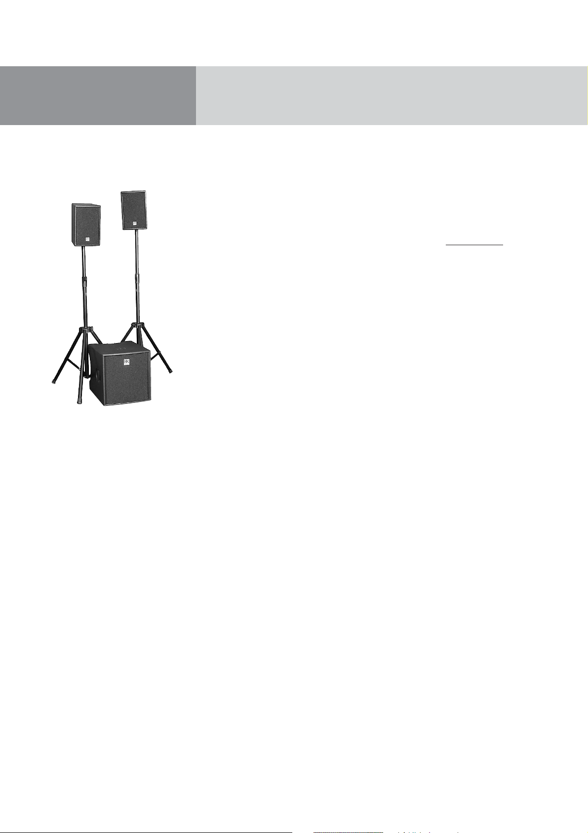
L.U.C.A.S IMPACT consists of two satellites and a
subwoofer equipped with a power amp and all the
electronics required to drive the bass bin and
satellite. Painstakingly fine-tuned to match the
speakers for the best possible sound and superior
impulse response, the electronic circuitry protects it
from overloads and makes this system so very easy
to operate.
You don't have to worry about tweaking frequencies
and finessing levels, all you have to do is set up the
system’s components, connect the signal-routing
and power cords, and you're ready to roll.
An HK AUDIO active system is so much more than
merely a pair of active cabinets on tripods; it is an
end-to-end sound-reinforcement solution consisting
of subwoofer, satellites and meticulously matched
circuitry.
Our engineers developed new technologies to satisfy
the stringent requirements of such an advanced
system. These unique features make this active
HK AUDIO sound reinforcement system stand out
from the crowd.
Best wishes from the HK AUDIO team. We hope you
enjoy your L.U.C.A.S IMPACT system as much as we
enjoyed developing it!
Garantie
Register your L.U.C.A.S IMPACT using the enclosed
warranty card to extend your warranty to five years
free of charge! Use the convenient Online Regis-
tration option at www
.hkaudio.com.
If you are unable to register online, please fill out
the enclosed warranty card completely and mail or
fax it to us.
Important note: Be sure to register the subwoofer
and satellites separately using one registration
card each.
The registration is only valid if the warranty
registration card is filled out and returned to
HK AUDIO
®
or the device is registered via the
Internet within 30 days of purchase. We are also
interested in learning where our products are used
and by whom. This information will help us design
future products. Your data is of course protected by
privacy laws.
Thank you!
HK AUDIO
®
Technical Service
Postfach 1509
66959 St. Wendel, Germany
Contents
1 L.U.C.A.S IMPACT System Components . . . . . .6
2 Transport . . . . . . . . . . . . . . . . . . . . . . . . . . . . . .6
3 Connections and Control Features . . . . . . . . . . .7
4 Tips and Tricks . . . . . . . . . . . . . . . . . . . . . . . . . .9
5 L.U.C.A.S IMPACT Accessories . . . . . . . . . . . . .9
6 Troubleshooting . . . . . . . . . . . . . . . . . . . . . . . .10
7 Technical Data . . . . . . . . . . . . . . . . . . . . . . . . .11
Page 6
5
DDO™ Controller technology
The DDO™ controller compensates for the varying
response of PA components such as low-frequency,
midrange and high-frequency speakers, power amps,
crossovers and so forth to forge a homogenous
system with uniform dynamics and a sonic image
with sharply defined contours.
Digital amping for enhanced efficiency and dynamic
response
With an efficiency rating topping the 90% mark,
Class-D digital power amps are substantially smaller,
lighter, and more compact than conventional amps.
The reduced thermal load on components enhances
reliability, while the far faster slew rate and higher
damping factor audibly enhances the speed and
precision of the system’s dynamic response.
Multi-band limiting and companding
Several matched limiters and companders are finetuned and optimised to process different frequency
ranges. This speaker-independent approach to signal
processing results in natural-sounding dynamic
response across the entire frequency spectrum and
produces a powerful yet finely balanced sonic image.
Subsonic filter
The integrated subsonic filter cuts unwanted ultralow frequencies. Infra sub-bass signals resulting
from stage rumble, wind or similar sources place
heavy demands on the power amp to render
frequencies so low that they exceed the useful range
of the speaker cabinet. The subsonic filter protects
the amp from these frequencies, thereby increasing
the entire system’s output power.
• Protects both power amps and speakers from
harmful ultralow frequencies.
• Enables cleaner and tighter bass response and
higher output levels.
Making the most of sonic energy with MonoTilt™
The newly developed, integrated MonoTilt ™ pole
mount allows sound energy to be utilized with great
efficiency. Troublesome ceiling reflections are
minimized; the sound is clearer, tighter, and more
focused.
Beyond that, the cabinet is stabilized at its center of
gravity - no wobbling, tilting, or unintentional
turning.
Easy setup and handling for less pre-gig stress
Like all HK AUDIO active rigs, L.U.C.A.S IMPACT
was conceived as a cohesive system comprising
painstakingly matched components. This rig was
engineered for easy portability and swift set-up.
Operation is simple, with no complicated tweaking
required.
• Genuine system design: All components are
precision-matched.
• Swift set-up & easy operation to save time
• Less stress = more fun + better music
Unique features for premium performance
English
Page 7

L.U.C.A.S IMPACT Manual 1.0
1 L.U.C.A.S IMPACT System
Components
Subwoofer
The L.U.C.A.S IMPACT subwoofer’s housing is split
into two chambers. The front chamber serves as the
speaker cabinet for the 15" direct-loaded loudspeaker, which has a power-handling capacity of
700 W RMS and a nominal impedance of 8 ohms.
The active electronic circuitry, the power unit,
DDO™ digital controllers and Class D power amps
are housed in a separate compartment at the rear of
the cabinet.
Satellites
Satellites are loaded with a 8" HK AUDIO Custom
speaker and a 1" compression driver with a 60° x 40°
CD horn. They are rated for 250 W RMS power-handling capacity and a nominal impedance of 8 ohms.
The newly developed, integrated MonoTilt ™ pole
mount allows sound energy to be utilized with great
efficiency. Troublesome ceiling reflections are
minimized; the sound is clearer, tighter, and more
focused.
Beyond that, the cabinet is stabilized at its center of
gravity - no wobbling, tilting, or unintentional
turning.
2 Transport
To transport the system, simply set the subwoofer
on its casters and place the satellites onto the subwoofer with the foam-rubber grille side facing down.
Secure the satellites, for example, using a locking
strap. Use original HK Audio L.U.C.A.S IMPACT
protective covers to gear up your personal system
for the rigors of the road. Amply padded and
protected against moisture, your L.U.C.A.S IMPACT
is sure to deliver satisfying performance for a long
time to come.
More about limiters
Limiters are designed to protect power amps and
the speakers connected to them from damage. The
functionality and response of a limiter is determined
by parameters called attack time, threshold and
release time. Adjusting these parameters incorrectly
can degrade the sound and bring about dynamic
distortion. At peak volume levels, for example,
vocals may fail to cut through the mix and
instruments that are played percussively may lose
their punch and dynamics.
HK AUDIO limiting technologies are more than
merely technical tools serving to protect components. We put a premium on authenticity, that is,
retaining an audio event’s true dynamics. This
explains why our limiters are first and foremost
designed to optimise the sound, though they of
course also protect the system.
Page 8
7
3 Connections and Control
Features
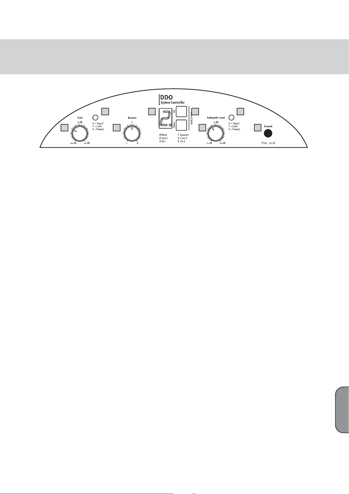
L.U.C.A.S IMPACT Subwoofer
1 Limiter LEDs
Much like rev counters, these LEDs indicate the
active system’s operating status. For more info, read
the sidebar “More about Limiter LEDs.”
2 Gain
Operation: Turn the Gain knob all the way down
(counterclockwise) before switching the system on.
Ensure the system is connected to the satellites and
all other connected components are on before
powering it up. Be sure to switch on the connected
mixer as well as all signal sources connected to it,
for example, keyboards, amps, effects, and so forth.
After you power the system up, set the Gain knob to
the 0 dBV or 12 o’clock setting. This is the preferred
level if you have connected a mixer. (Note: If you
connect a CD player or a keyboard directly to the
system, you may not be able to achieve peak volume
at this setting. If this is the case, twist the Gain knob
to the far right.)
If you hear distortion or a saturated signal, first
check the signal sources and, if possible, reduce the
output signal level there. If you are unable to turn
down the level of the signal sent to L.U.C.A.S
IMPACT at the signal source, adjust the input
sensitivity using the Gain knobs. (see also Tips and
Tricks—section 4).
3 Balance
Operation: Twist the Balance knob to the left or right
to adjust the relative balance of levels between the
left and right channels.
4 Display
Display: The numeric display indicates the currently
selected system configuration (0 to 5).
0 Mute - System switched to silent mode.
Zero sound signal reproduction.
1 Speech - Set-up for speech.
This mode places emphasis upon vocal and spoken
language reproduction. To minimize subsonic interference and background noise over the microphone,
the subwoofer level is reduced.
2 Live 1 - Set-up 1 for use during live performance.
The Live 1 setup enables punchy, dynamic bass with
rapid transient response. Vocals are likewise
predominant in this sound profile.
3 Live 2 - Set-up 2 for use during live performance.
The Live 2 set-up delivers softer and deeper bass
reproduction at a slightly lower level. The vocals are
slightly less in the foreground when compared to the
Live 1 set-up.
4 DJ 1 - Set-up 1 for reproduction of music from
CDs.
The DJ 1 set-up provides an ideal setting for CD
reproduction, with strong deep bass, discreet
midrange and accentuated highs.
5 DJ 2 - Set-up 2 for reproduction of CD/ MP3
music.
Like DJ1 above, the DJ 2 set-up can also be used for
CD reproduction, but is optimised for MP3-encoded
sources to revitalize the sound with more dynamic
bass, smoother highs and a more natural, less
compressed sound.
Note: A flashing display indicates that the controller
has muted the input. This mute function is triggered
via the input signal level. The system is muted when
its level falls below the threshold value. The system
is enabled as soon as the input signal level rises
above the threshold value.
5 Up/Down Buttons
Press these buttons to change system configurations. Operation: Simultaneously press and hold the
Up and Down buttons for about 1-2 seconds. Once
the letter U (Unlock) appears briefly in the display
you can use the Up and Down buttons to select the
desired setup. The buttons lock again automatically
after a moment, at which time the letter L (Lock)
appears briefly in the display.
6 Subwoofer Level
Handling: When this knob is set to the 12 o’clock
position, the subwoofer’s and the satellite’s
respective volumes are matched, ensuring the
proper balance between the subwoofer’s bass output
and the stallites’ mid/high-range output. If desired,
you can twist the Subwoofer Level knob to the left,
i.e. counterclockwise, to cut the subwoofer’s level by
as much as -12 dB and to the right to boost it by as
much as 6 dB.
7 Ground
Ground lift button for separating the signal and
chassis ground in the event of hum. To rid the
system of low-frequency hum, press the Ground
switch in. If this doesn’t solve the problem, check all
power and audio cables connected to L.U.C.A.S
IMPACT for damage, as well as all cables routing
signals to the mixing console (see also Tips and
Tricks in Section 4).
L.U.C.A.S IMPACT -- user panel
2 3 6 7
1 4 5 1
English
Page 9
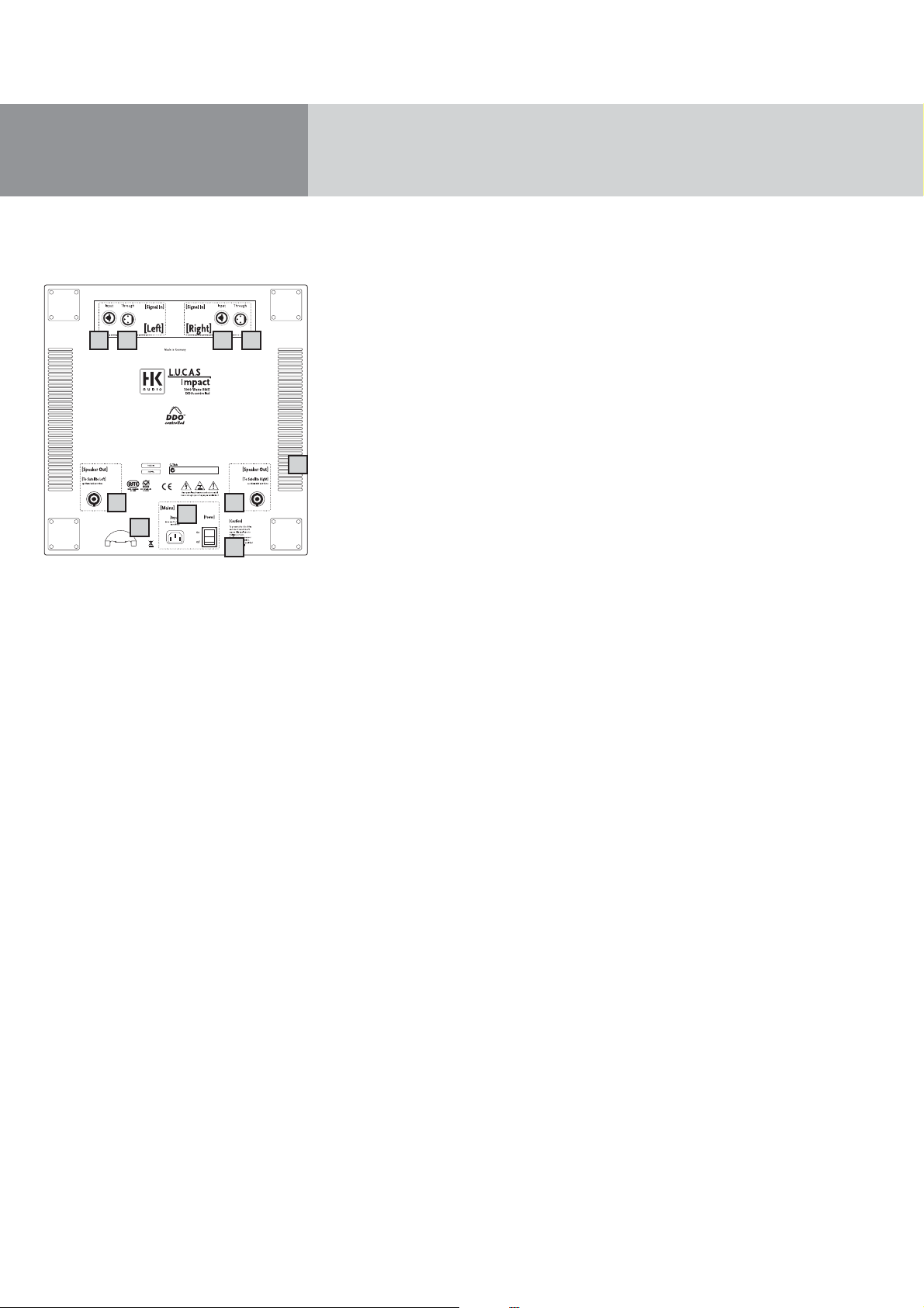
L.U.C.A.S IMPACT Manual 1.0
8 Input Left and Input Right (Combination XLR/1/4"
jacks)
L.U.C.A.S IMPACT is equipped with separate left and
right channel inputs for connecting to a mixer.
Connections: Connect the audio cables that route
the signal coming from your mixer (master
left/right, line out, or a similar circuit) to these
balanced inputs using microphone cables equipped
with XLR connectors. The XLR connectors’ pin
assignments must be as follows:
1= ground, 2= +, 3= -.
You can also use a 1/4" Tip-Ring-Sleeve plug to route
signals via balanced circuits. Unbalanced signals can
be patched in via a mono plug.
9 Through Left, Through Right
Connections: Parallel outputs for routing the line
signal (left or right) to other systems, outboard components, monitor power amps, etc., via XLR cables
10 Speaker Out (To Satellite Left und Right)
Connections: Connect these Speakon
®
outputs to
the left and right L.U.C.A.S IMPACT satellites using
speaker cables equipped with Speakon
®
connectors.
Note: Be sure to rotate the Speakon
®
connectors
clockwise until they lock in place!
11 Power Switch
Operation: On/off switch for the active system.
The display on the system controller glows orange to
indicate that the system is on.
Note: Once you have engaged the Power switch, it
will take several seconds for the display to light up
and the system to be ready for operation. This is
standard procedure and does not indicate a malfunction.
The active L.U.C.A.S IMPACT system should always
be switched on last after you power up all equipment connected to it, and should be switched off
first before you switch off all the other equipment
connected to it.
12 Mains Input
Connections: Use the factory-included mains cable
(power cord) to connect from this socket to a wall
receptacle. Caution! Make sure the local mains
voltage matches the voltage specified on the device.
Connecting the system to the wrong mains voltage
may destroy the L.U.C.A.S IMPACT system’s
electronic components.
13 Mains Cable Tab
Clamp the power cable into the tab to prevent it
from being pulled out inadvertently.
14 Fans
These fans (on the side and back of the housing)
keep the power amp modules cool. Always keep the
fan and ventilation vents free of dirt and debris, and
ensure they remain unobstructed so air can circulate
freely.
L.U.C.A.S IMPACT Satellite
Input
Connections: Connect the Speakon
®
inputs to the
left and right L.U.C.A.S IMPACT satellite outputs
using speaker cables equipped with Speakon“
connectors.
Note: Be sure to twist the Speakon
®
connectors
clockwise until they lock in place! You must first
disengage the safety catch before you can unplug
the connector. To do this, pull the bayonet catch
towards the cord.
8
12
13
14
11
10 10
9 8 9
L.U.C.A.S IMPACT - user panel rear
Page 10

9
4 Tips and Tricks
• Do not expose electronic circuitry to moisture!
When you set the system up outdoors, be sure to
protect it against rain. Keep soft drinks, beer or any
other liquids well away from the cabinets to protect
their electronic components from short circuits.
• To ensure proper ventilation, make sure the subwoofer is placed a sufficient distance away from
walls and isn’t covered by curtains and the like.
This is vital to keep the power amps cool.
• Ensure that the vents on the subwoofer’s side
panels are free of dirt and that the fan blades can
rotate freely. Otherwise, electronic components
may overheat and suffer damage.
• L.U.C.A.S IMPACT takes care of delivering
optimum sound—so provide it with optimum
input signals! Noise such as hum is generally
caused by defective cables, the wrong type of cables, or unbalanced signals being fed to the mixing
console. Check all audio cables and mains cables.
• Avoid distortion! Not only is it unpleasant to your
audience’s ears, it also endangers your equipment.
Make sure all components that are connected
directly and indirectly to L.U.C.A.S IMPACT have
sufficient power ratings, and that they are not
distorting from being driven at their respective
limits. Provide a clean, undistorted signal to the
system that won’t require backing off the Gain
knob to clean it up.
• Avoid ground loops! If, for example, you connect
the mixer to one mains circuit/wall outlet, and
L.U.C.A.S IMPACT to another, you may encounter a
ground loop. To prevent this problem, always
connect the L.U.C.A.S IMPACT system and the
mixing console to the same electrical circuit (same
phase!). If your equipment hums despite this precaution, the Ground Lift switch can be a great help.
CAUTION: Never tape over the plug’s ground
terminal – this endangers lives!
5 L.U.C.A.S IMPACT Accessories
HK AUDIO Speaker Add On Package
This is the complete L.U.C.A.S IMPACT accessory kit
consisting of two aluminum cabinet tripods, one gig
bag, and two speaker cables.
HK AUDIO Protective Covers for L.U.C.A.S IMPACT
This set comprises one cover for the subwoofer and
two covers for the satellites. Tear-resistant and
water-repellant, these rugged covers are thickly
padded to afford lasting protection for the L.U.C.A.S
IMPACT system during transport.
To learn more about Original HK Audio Accessories,
talk to your HK AUDIO dealer or visit
www.hkaudio.com.
English
Page 11
L.U.C.A.S IMPACT Manual 1.0
6 Troubleshooting
The display does not light up when switched on.
1 Check if the power cable is plugged into the Mains
Input.
2 Check if the mains power supply is providing
current.
The display lights up, but there is no sound coming
from the cabinets.
1 Check the cables connected to the Left and Right
inputs.
2 Check if the signal sources (mixer, keyboard, CD
player) are on.
3 Is the Gain knob turned up?
4 Check the speaker cables for damage.
5 Check if the Speakon“ connectors are fully engaged
in their sockets (rotated to the right). They must be
locked in place to establish an electrical
connection.
The subwoofer’s low frequency output is too soft.
1 Check the setting of the Subwoofer Level knob.
Adjust this knob to set the volume of the subwoofer to the desired level.
Sound seems distorted.
1 Check the LED displays on your mixer. They should
not be constantly in the red. If necessary, reduce
the volume at the mixer.
2 If the LED displays on your mixer are in the green,
turn back L.U.C.A.S IMPACT’s Gain knob.
3 Watch the LEDs of the Limit Left, Limit Right and
Limit Subwoofer displays on L.U.C.A.S IMPACT’s
control panel. These may light up yellow, but only
intermittently. Under no circumstances may they
continuously illuminate yellow. If this is the case,
turn the Gain down (knob counterclockwise).
Annoying hum
1 Check the cables connecting the source of the
audio signal to L.U.C.A.S IMPACT. Replace any
damaged cords.
2 If you cannot pinpoint the cause of the humming,
press the Ground switch in. This should remedy
the problem in most cases.
This is to certify that
HK AUDIO®L.U.C.A.S IMPACT
complies with the provisions of the Directive of
the Council of the European Communities on the
approximation of the laws of the Member States
relating to electromagnetic compatibility (EMC
Directive 89/336/EEC) and the low voltage Directive
(73/23/EEC). This declaration of conformity of the
European Communities is the result of an examination
carried out by the Quality Assurance Department
of STAMER GmbH in accordance with European
Standards EN 50081-1, EN 50082-1and EN 60065
for low voltage, as laid down in Article 10 of the
EMC Directive.
Stamer Musikanlagen
GmbH*
Magdeburger Str. 8
66606 St.Wendel
Lothar Stamer Dipl.Ing.
Managing Director
St.Wendel, 01/03/06
* Stamer Musikanlagen manufactures exclusively
for HK AUDIO
®
.
Page 12

11
7 Technical Specifications
L.U.C.A.S IMPACT Subwoofer
Line In: XLR female (pin 1= ground; 2= +, 3= -)
Input: Electronically balanced & floating
Input impedance: 47 k ohms
Sensitivity: 0 dBV (=1V)
Max. input level: + 20 dBu
Parallel out: XLR male (pin 1= ground; 2=+, 3= -)
Speaker outputs: Speakon
®
NL 4 (pin 1+= +, 1-= -)
Digital controller:
Sampling frequency: 24 bits/ 48 kHz
Internal signal processing: 56 bits
Amplifiers:
Subwoofer output: 1x 700 W RMS / Class D power amp
Satellites output: 2x 250 W RMS / Class D power amp
Protective circuits: DDO™ controlled multi-band limiter
Speakers:
Woofer: 1x 15"
Subwoofer frequency response: 45 Hz -130 Hz, ± 3 dB
36 Hz -130 Hz, - 10 dB
SPL 1W / 1m: 101 dB (half space)
Max. SPL / 1m: 127 dB @ 10% THD (half space)
Weights and measures:
Weight: 32 kg / 70.4 lbs.
Dimensions without casters: 47.5 cm x 47 cm x 58.5 cm
(WxHxD) 18 3/4 " x 18 1/2" x 23"
L.U.C.A.S IMPACT Satellite
Inputs:
Speaker input: Speakon NL 4 (pin 1+= +, 1-= -)
Speakers:
Woofer: 1x 8“
Driver: 1x 1"
Directivity: 60°x 40° CD horn
Overall nominal impedance: 8 ohms
Nominal power handling: 250 W RMS
SPL 1W / 1m: 103 dB (half space)
Max. SPL / 1m: 125 dB @ 10% THD (half space)
Frequency response: 130 Hz - 19 kHz, +/- 3 dB
(via DDO™ Controller)
Crossover frequency (passive): 2.2 kHz/ 12 dB / octave
Driver protection: Dynamic protective circuit
Pole mount: HK Audio MonoTilt™ 36 mm, -10°
Weights and measures:
Weight: 7.5 kg / 16.5 lbs.
Dimensions (WxHxD): 25.8 cm x 38.5 cm x 28.5 cm
10 1/8" x 15 1/8" x 11 1/4"
General electrical data::
Protection class 1 (protectively earthed)
Max. current consumption: 4.4 A (220 – 240 V) • 8 A (110 – 120 V)
Max. power consumption: 1000 Watts
Mains voltage range: +/- 10%
Internal fuses: 250V/ T 8A IEC127
Ambient temperature range during operation: -10° C to +35° C
English
Page 13

DRAWING-NUMBERS
EXAMPLE
HK0106-EX-R01-1A
PROJECT-NR.:
HK = HK AUDIO
HU = HUGHES&KETTNER
MP = MINDPRINT
CHARACTER:
BL = SHEET METAL / BLECH
EX = EXPLODED DRAWING / EXPLOSIONSZEICHNUNG
HZ = CABINET / HOLZGEHÄUSE
KU = PLASTIC / KUNSTSTOFF
LP = PCB / LEITERPLATTEN
SO = MISCELLANEOUS / SONSTIGES
SP = SCHEMATIC / SCHALTPLÄNE
TR = TRANSFORMER / TRANSFORMATOR
GK = WIRING DIAGRAM / GERÄTEVERKABELUNG
DEPARTMENT:
R = R&D
SERIAL NUMBER
VERSION
REVISION
Page 14

Stand
W
Y
r
Standard for single wire confection.
16 B 150 638 I - 485 W Z I 1015
style 1015 according UL specifications
I = completely insulated with black shrinktube or appropriate sleeve
IT = partly insulated; only crimp connection insulated.
no marking = without insulation
Z = with additional junction
no marking = without additional junction
W = angled faston
no marking = straight faston
17. Jun 04
Faston connector brass tin-plated DIN 46245
638 = 6,3 * 0,8 [mm]
488 = 4,8 * 0,8 [mm]
485 = 4,8 * 0,5 [mm]
288 = 2,8 * 0,8 [mm]
285 = 2,8 * 0,5 [mm]
abiso = 5mm bared and tin-plated (teilabzug)
text for special constructions, (for example. 4mm ringshaped faston)
the larger faston connector always mentioned at first. (Nathan drawing number controlling)
lenght in mm within a 50 mm raster
colour
B = black (phase conductor)
R = red
BR = brown
BL = blue (neutral conductor)
= white
G = yellow-green (ground bonding/ earthing connection)
if fully insulated (I) insulation with blue shrinktube
if partly insulated (IT) use IF 602 485 .
if fully insulated (I) insulation with blue shrinktube
if partly insulated (IT) use IF 602 485
cross section
16 = AWG 16 (prefered usage)
Q1.5 = H07VK 1,5mm² (prefered usage)
wire designation:
P + lfd Nr. = AWG single wire black, red, blue, brown or white
E + lfd Nr. = AWG single wire green- yellow
L + lfd N
FQL + lfd Nr. = crossover wiring H07VK
Regarding special wirings like wiring harness or similar, drawings will be prepared and appropriate
. = twisted AWG double wire, lenght specification always in twisted condition
drawing numbers will be stored in the article archive.
Page 15

Confidential, for authorized service technicians only! Do not disclose
this information to or share these documents with third parties.
TECHNICAL SERVICE:
Stamer Musikanlagen GmbH • Magdeburger Str. 8 • 66606 St.Wendel • Germany
Music & Sales P.E. GmbH • Leipziger Str. 3 • 66606 St.Wendel • Germany
Service Documents
HK1005
L.U.C.A.S
IMPACT
SUB
Page 16

10E 974017
HK1005-HZ-R02-1D
22
28E 994184
Q1.5 R 1000 638I-488I
2E 400275
Q1.5 S 1000 638I-488I
21E 976115
HK1005-EX-R04-1B
3E 502190
15E 974355
15
5E 962292
4E 962291
15
HK1005-EX-R03-1B
14E 974322
9E 974011
16E 974454
11E 974108
1E 340142
6E 970451
12
19
16
13
7E 972008
22 E 976159
8E 972047
18E 974475
16
20 E 976009
13 E 974233
12 E 974220
16
11
18
19 E 976001
17 E 974455
TITEL:
INDEX
1B-201106
ÄNDERUNG
rubberfoot with screw+plug AD= 1705 PA
removed
ZEICHNER
C. Loris
C. Lorisupdate for service-manual1C-231007
66606 St. Wendel / Germany
ZEICHNUNGS-NR.:
ERSTELLT VON:
GEPRÜFT/
FREIGEGEBEN VON:
WERKSTOFF:
DATEINAME:
HK1005-EX-R05-1C
C. LORIS 1
HK1005-EX-R05-1C-GESAMT_BASS
HK1005-IMPACT SUBWOOFER
EXPLODED DRAWING COMPLETE
OBERFLÄCHE:
VERSION:
AM:
23.10.2007
AM:
n/a
REVISION:
BLATT:
2
BLÄTTER
C1
Page 17

pos. no. part-no. 1 description Beschreibung quantity
1 340142 front grille assembly Impact subwoofer Lucas Impact Frontgitterbaugruppe 1
2 400275 wooden cabinet Lucas Impact subwoofer Holzgeh. Lucas Impact Bass 1
3 502190 chassis Lucas Impact 100-240V Chassis Lucas Impact 100-240V 1
4 962291 stranded wire, color: red, 1000mm Litze FQL21 rot 1000mm 1
5 962292 stranded wire, color: black, 1000mm Litze FQL21 schwarz 1000mm 1
6 970451 front grill reeinforcement profile 15" Blech Verstrebungswinkel 15" 1
7 972008 damping wool Dämmwolle Hochbauschvlies 0,50 qm
8 972047 PE-foam tube PE-Schaumstoff-Röhrchen 8
9 974011 hexagon socket head cap screw, M6x25, black Inbusschraube M6*25 sw 4
10 974017 hexagon socket countersunk head screw, M6x25, black Inbussenkschraube M6x25 sw 4
11 974108 plastic PCB spacer, 6.2x10x15, Polyamid black Dist.Hülse PE 6,2*10*15 [mm] 2
12 974220 hexagon socket countersunk head screw, M6x40, black Inbussenkschraube M6x40 sw 2
13 974233 washer, form A, D=6.4mm, zinc plated Unterleg-Scheibe 6,4 vz 2
14 974322 ABC-Spax-S screws for backwall, 4x20, black Rückwandschraube, 4*20 sw 2
15 974355 cross recessed panhead tapping screw with collar, 3.9x30, black Blechschr. KFR-Kopf 3,9* 30 sw 14
16 974454 plastic PCB spacer, 6.2x10x10, Polyamid black Dist.Hülse PE 6,2*10*10[mm] 4
17 974455 ABC-Spax-S chipboard screw, panhead Z, 5x16, black Pan Head-Z ABC-Spax sw 5*16 4
18 974475 hexagon socket head cap screw, M6x50, black Inbusschraube M6*50 sw 2
19 976001 rubber foot square, self-adhesive, black Gummifuss quadr. selbstkleb. sw 2
20 976009 rubber foot D38*H11 [mm] Gummifuss D38*H11 [mm] 4
21 976115 connector plate, M20 Befestigungsplatte M20 1
22 976159 plastic dish Premium One Griffinnenschale Premium One 2
23* 982037 sealing tape 2x6mm Iso-Zell-Band fadenvers. 2*6mm 0,22 lfdm
24* 982044 sealing tape 2x15mm Iso-Zell-Band fadenvers. 2*15mm 1,54 lfdm
25* 982078 sealing tape 2x20mm Iso-Zell-Band fadenvers. 2*20mm 0,50 lfdm
INDEX
1B-201106
26* 986016 foam glue, Alfa D 4572 Klebstoff Alfa D 4572 xxx
27* 988165 1k polyurethane glue, 310mltrs. tube Polyurethan 1-K Kleber, 310ml Kartusche xxx
28 994184 B&C 15NW76-8OHMS 3" Coil B&C 15NW76-8OHMS 3" Coil 1
ÄNDERUNG
rubberfoot with screw+plug AD= 1705 PA
removed
ZEICHNER
C. Loris
C. Lorisupdate for service-manual1C-231007
66606 St. Wendel / Germany
ZEICHNUNGS-NR.:
ERSTELLT VON:
GEPRÜFT/
FREIGEGEBEN VON:
WERKSTOFF:
DATEINAME:
HK1005-EX-R05-1C
C. LORIS 2
HK1005-EX-R05-1C-GESAMT_BASS
TITEL:
HK1005-IMPACT SUBWOOFER
EXPLODED DRAWING COMPLETE
VERSION:
AM:
23.10.2007
AM:
OBERFLÄCHE:
n/a
REVISION:
BLATT:
2
C1
BLÄTTER
Page 18

14E 972041
1E 547056
16
24E 976007
25E 976008
5
16E 974110
6E 950055
9
27 E 976141
10 E 959068
20 E 974290
12 E 970769
HK1105-BL-R03-1A
2E 600088
11E 970767
4 E 931304
HK1105-BL-R02-1C
9 E 952305
23E 974521
28E 976169
22
21E 974356
23
15
18 E 974228
22 E 974416
23E 974521
16 E 974110
3 E 600089
17 E 974197
INDEX
1B-171007 C. Loris
ÄNDERUNG
neuer Schiebeschalter u. Speakonbuchse, Verkabelung aktualisiert
ZEICHNER
19 E 974271
26 E 976125
15 E 974007
7 E 950060
8 E 952260
13 E 970771
HK1005-BL-R02-1D
5 E 943239
HK1105-SO-R07-1A
66606 St. Wendel / Germany
ZEICHNUNGS-NR.:
ERSTELLT VON:
GEPRÜFT/
FREIGEGEBEN VON:
WERKSTOFF:
DATEINAME:
HK1005-EX-R04-1B
C. LORIS 1
HK1005-EX-R04-1B-CHASSIS
TITEL:
HK1005-IMPACT SUBWOOFER
EXPLODED DRAWING CHASSIS
VERSION:
AM:
17.10.2007
AM:
OBERFLÄCHE:
n/a
REVISION:
BLATT:
5
B1
BLÄTTER
Page 19

pos. no. part-no. 1 description Beschreibung quantity
1 547056 54 Lucas Impact Preamp Assembly 54 Lucas Impact Vorstufe 1
2 600088 60 Inputboard Lucas Max 60 Inputboard Lucas Max 1
3 600089 60 Mains Filter Lucas Impact 100-240V 60 Netzfilt.Lucas Imp 100-240V 1
4 931304 ferrite teroid core, 25x15x12 Ferritring, geschlossen 25x15x12 2
5 943239 dust protection, acoustic foam, black, PPI15, 5mm Staubschutz Lucas Max "07" 2
6 950055 Slide Switch 2xum T22205B Schiebeschalter 2xum T22205B 1
7 950060 hi-inrush, mains rocker switch, C13150VB Netzschalter gross C1350VB 1
8 952260 power inlet, type 6100.3300, Schurter Netzbuchse Typ 6100.3300 1
9 952305 speakon chassis connector, NL4MP-3 Speakonbuchse 4pol eckig, NL4MP-3 2
10 959068 QuadAMP, 4ch PWM unit, RD0303 QuadAMP, 4ch PWM Modul, RD0303 1
11 970767 LUCAS MAX, preamp cover plate Blech Lucas MAX Vorstufemodul 1
12 970769 Lucas Max castor stabilizer Blech Lucas Max Stützwinkel 4
13 970771 Subwoofer Sheet Metal Chassis, Lucas Impact Blech Lucas Impact Bass Chassis 1
14 972041 rubber punching 25x25x15 Zellkaut.-Stanzteil 25x25x15 2
15 974007 hexagon socket oval head screw, M3x6, black Linsenschr.m.Innens. M3*6 sw 8
16 974110 self locking hexagon nut with plastic insert, M3, zinc plated Stopmutter M3 vz 9
17 974197 hexagon PCB spacer, type B, M3x8, zinc plated Dist. Bol Innen/Außengew. M3*8 vz 3
18 974228 cross recessed raised countersunk screw, M3x10, black Linsensenkschraube M3*10 sw 2
19 974271 cross recessed raised countersunk screw, M3x8, black Linsensenkschraube M3*8 sw 2
20 974290 self locking hexagon nut with plastic insert, M4, zinc plated Stopmutter M4 vz 4
21 974356 blind rivet steel standard, 6x10, black Blindniete Stahl schw. 6*10 16
22 974416 cross rec. raised counters. tap. screw w. cutting slot, 2.9x6.5, black Senkschr. f. Kunststoff 2,9*6,5, sw 4
23 974521 cross rec. raised counters. tap. screw w. cutting slot, 2.9x9.5, black Senkschr. f. Kunststoff 2,9*9,5, sw 8
24 976007 cable tie 2,5x100 (mm) Kabelbinder natur 2,5x100 (mm) 12
25 976008 cable tie 2,6x200 (mm) Kabelbinder natur 2,6x200 (mm) 1
26 976125 mains cable strain relief, HKAudio custom made Kabelhalter HK Audio 1
27 976141 rubberbuffer 15x15 B Gummipuffer GM-Puffer 15x15 B 4
28 976169 Swivel castor LPA-TPA 75K-FK, black Lenkrolle 75mm RAL2005 schwarz 4
29* 986016 foam glue, Alfa D 4572 Klebstoff Alfa D 4572 xxx
30* 988206 pre-cut part transfer tape 1573 Transferbandzuschnitt 1573 0,30 lfm
INDEX
1B-171007 C. Loris
ÄNDERUNG
neuer Schiebeschalter u. Speakonbuchse, Verkabelung aktualisiert
ZEICHNER
66606 St. Wendel / Germany
ZEICHNUNGS-NR.:
ERSTELLT VON:
GEPRÜFT/
FREIGEGEBEN VON:
WERKSTOFF:
DATEINAME:
HK1005-EX-R04-1B
C. LORIS 2
HK1005-EX-R04-1B-CHASSIS
TITEL:
HK1005-IMPACT SUBWOOFER
EXPLODED DRAWING CHASSIS
VERSION:
AM:
17.10.2007
AM:
OBERFLÄCHE:
n/a
REVISION:
BLATT:
5
B1
BLÄTTER
Page 20

2
10
1
9
INDEX
1B-171007 C. Loris
ÄNDERUNG
neuer Schiebeschalter u. Speakonbuchse, Verkabelung aktualisiert
ZEICHNER
9
TITEL:
HK1005-IMPACT SUBWOOFER
3
8
66606 St. Wendel / Germany
ZEICHNUNGS-NR.:
ERSTELLT VON:
GEPRÜFT/
FREIGEGEBEN VON:
WERKSTOFF:
DATEINAME:
HK1005-EX-R04-1B
C. LORIS 3
HK1005-EX-R04-1B-CHASSIS
EXPLODED DRAWING CHASSIS
OBERFLÄCHE:
VERSION:
AM:
17.10.2007
AM:
n/a
REVISION:
BLATT:
5
B1
BLÄTTER
Page 21

E965617, Flachb. 20-2-150mm Typ 5,
AWG 28 flexibel grau RM1,27
E962030, Litze E5 grün-gelb 200mm,
AWG 16 Style 1015
16-YG-200-638-638 1015
E 962050
stranded wire 1*JST 3pol 140mm
E965607, Flachb. Flachb. 10-2-150mm Typ 5
AWG 28 flexibel grau RM1,27
E965617, Flachb. 20-2-150mm Typ 5,
AWG 28 flexibel grau RM1,27
E965626, Flachb. 20-2-200mm Typ 5,
AWG 28 flexibel grau RM1,27
All DIP switches are off
E962261, Litze P23 schwarz 300mm,
16-B-300-488I-485IT 1015
E962261, Litze P23 schwarz 300mm,
16-B-300-488I-485IT 1015
E962081, Litze TRI 1 schwarz 110mm,
16-B-110-638I-638I 1015
E962255, Litze P29 blau 120mm,
16-BL-120-638I-638I 1015
E962293, Litze P26 rot 350mm,
16 R 350 488I-485IT 1015
E962293, Litze P26 rot 350mm,
16 R 350 488I-485IT 1015
E 962291
Q1.5-R-1000-638I-488I
+
-
E 962292
Q1.5-B-1000-638I-488I
INDEX
1B-171007 C. Loris
ÄNDERUNG
neuer Schiebeschalter u. Speakonbuchse, Verkabelung aktualisiert
ZEICHNER
E964050, Powerkabel Lucas Impact,
HK1005-KA-R01-1B
E962255, Litze P29 blau 120mm,
16 B 120 638I-638I 1015
E962081, Litze TRI 1 schwarz 110mm,
16-B-110-638I-638I 1015
E962038, Litze E4 grün-gelb 120mm,
16-YG-120-638-638 1015
66606 St. Wendel / Germany
ZEICHNUNGS-NR.:
ERSTELLT VON:
GEPRÜFT/
FREIGEGEBEN VON:
WERKSTOFF:
DATEINAME:
HK1005-EX-R04-1B
C. LORIS 4
HK1005-EX-R04-1B-CHASSIS
TITEL:
HK1005-IMPACT SUBWOOFER
EXPLODED DRAWING CHASSIS
VERSION:
AM:
17.10.2007
AM:
OBERFLÄCHE:
n/a
REVISION:
BLATT:
5
B1
BLÄTTER
Page 22

Pos. Artikel-Nr. 1 Artikel-Nr. 2 Artikel-Nr. 3 description Titel Menge
1 962030 stranded wire 16-YG-200-638-368 1015 Litze 16-YG-200-638-368 1015 1
2 962038 stranded wire 16-YG-120-638-638 1015 Litze 16-YG-120-638-638 1015 1
3 962050 stranded wire 1*JST 3pol 140mm Litze 1*JST 3pol 140mm 1
4 962081 stranded wire 16-B-110-638I-638I 1015 Litze 16-B-110-638I-638I 1015 2
5 962255 stranded wire 16-BL-120-638I-638I 1015 Litze 16-BL-120-638I-638I 1015 2
6 962261 stranded wire 16-B-300-488I-485IT 1015 Litze 16-B-300-488I-485IT 1015 2
7 962291 stranded wire Q1.5-R-1000-638I-488I Litze Q1.5-R-1000-638I-488I 1
8 962292 stranded wire Q1.5-B-1000-638I-488I Litze Q1.5-B-1000-638I-488I 1
9 962293 stranded wire 16-R-350-488I-485IT 1015, AWG, UL, CSA Litze 16-R-350-488I-485IT 1015, AWG, UL, CSA 2
10 964050 powercable Lucas Impact Powerkabel Lucas Impact 1
11 965607 flat ribbon cable 10-2-150 typ 5 Flachbandkabel 10-2-150 typ 5 1
12 965617 flat ribbon cable 20-2-150mm typ 5 Flachbandkabel 20-2-150mm Typ 5 2
13 965626 flat ribbon cable 20-2-200mm typ 5 Flachbandkabel 20-2-200mm typ 5 1
INDEX
1B-171007 C. Loris
ÄNDERUNG
neuer Schiebeschalter u. Speakon-
ZEICHNER
buchse, Verkabelung aktualisiert
66606 St. Wendel / Germany
ZEICHNUNGS-NR.:
ERSTELLT VON:
GEPRÜFT/
FREIGEGEBEN VON:
WERKSTOFF:
DATEINAME:
HK1005-EX-R04-1B
C. LORIS 5
HK1005-EX-R04-1B-CHASSIS
TITEL:
HK1005-IMPACT SUBWOOFER
EXPLODED DRAWING CHASSIS
VERSION:
AM:
17.10.2007
AM:
OBERFLÄCHE:
n/a
REVISION:
BLATT:
5
B1
BLÄTTER
Page 23

pos. no. part-no. 1 description Beschreibung quantity
1 970335 front grille Streckgitter 1
2 972085 acoustic foam anthracite 15mm Akustikschaum Anthrazit 15mm 1
3 974158 snapon retaining ring (for logo) Schnellbefestiger f. Logo 1
4 980105 logo ´HK Audio´ 55x55 mm Logo ´HK Audio´ 55x55 mm 1
HK1005-SO-R06-1A
3 E 974158
2E 972085
1 E 970335
HK1005-SO-R01-1A
service-nr.: E 340142
INDEX
ÄNDERUNG
ZEICHNER
1B-231007 update for service-manual C. Loris
4E 980105
TITEL:
HK1005-IMPACT SUBWOOFER
66606 St. Wendel / Germany
ZEICHNUNGS-NR.:
ERSTELLT VON:
GEPRÜFT/
FREIGEGEBEN VON:
WERKSTOFF:
DATEINAME:
HK1005-EX-R03-1B
C. LORIS 1
HK1005-EX-R03-1B-FRONTGITTER_BASS
EXPLODED DRAWING FRONT GRILLE
OBERFLÄCHE:
VERSION:
AM:
23.10.2007
AM:
n/a
REVISION:
BLATT:
1
B1
BLÄTTER
Page 24

TITEL:
ERSTELLT VON:
BLATT:
AM:
ZEICHNUNGS-NR.:
66606 St. Wendel / Germany
VERSION:
REVISION:
GEPRÜFT/
FREIGEGEBEN VON:
AM:
WERKSTOFF:
OBERFLÄCHE:
DATEINAME:
BLÄTTER
INDEX
ÄNDERUNG
ZEICHNER
HK1005-EX-R06-1B-CROSSOVER
HK1005-SATELLITE CROSSOVER
EXPLOSION DRAWING
HK1005-EX-R06-1B
C. LORIS 1
4
20.11.2006
B1
n/a
HK1005-BL-R03-1E
2 E 952022
5E 974107
4E 974105
6 E 974110
8E 974290
9E 974465
7 E 974228
3 E 970797
1E 520123
pos.no. part-no. 1 description Bezeichnung quantity
1 520123 52 crossover circuit PCB, Impact Top 52 Freqw. Lucas Impact Top 1
2 952022 speakon chassis connector, NL4MP Speakonbuchse 4pol eckig 1
3 970797 Lucas Impact Top Connection Panel Blech Anschl.pl.Lucas Impact Top 1
4 974105 hexagon nut, class 8, M5, zinc plated Sechskantmutter M4 vz 4
5 974107 plastic PCB spacer, 4.2x8x10, Polyamid black Dist.Hülse PE 4,2*8*10 [mm] 8
6 974110 self locking hexagon nut with plastic insert, M3, zinc
plated
Stopmutter M3 vz 2
7 974228 cross recessed raised countersunk screw, M3x10, black Linsensenkschraube M3*10 sw 2
8 974290 self locking hexagon nut with plastic insert, M4, zinc
plated
Stopmutter M4 vz 4
9 974465 hexagon socket countersunk head screw, M4x35, black Inbussenkschraube M4x35 sw 4
1B 201106
PCB SCREW-CONNECTION
C. LORIS
Page 25

TITEL:
ERSTELLT VON:
BLATT:
AM:
ZEICHNUNGS-NR.:
66606 St. Wendel / Germany
VERSION:
REVISION:
GEPRÜFT/
FREIGEGEBEN VON:
AM:
WERKSTOFF:
OBERFLÄCHE:
DATEINAME:
BLÄTTER
INDEX
ÄNDERUNG
ZEICHNER
HK1005-EX-R06-1B-CROSSOVER
HK1005-SATELLITE CROSSOVER
EXPLOSION DRAWING
HK1005-EX-R06-1B
C. LORIS 2
4
20.11.2006
B1
n/a
1
1B 201106
PCB SCREW-CONNECTION
C. LORIS
Page 26

TITEL:
ERSTELLT VON:
BLATT:
AM:
ZEICHNUNGS-NR.:
66606 St. Wendel / Germany
VERSION:
REVISION:
GEPRÜFT/
FREIGEGEBEN VON:
AM:
WERKSTOFF:
OBERFLÄCHE:
DATEINAME:
BLÄTTER
INDEX
ÄNDERUNG
ZEICHNER
HK1005-EX-R06-1B-CROSSOVER
HK1005-SATELLITE CROSSOVER
EXPLOSION DRAWING
HK1005-EX-R06-1B
C. LORIS 3
4
20.11.2006
B1
n/a
962074-Litze FQL24 red 450mm
Q1.5 R 450 638-ABISO
962073-Litze FQL24 black 450mm
Q1.5 B 450 638-ABISO
962073-Litze FQL24 black 450mm
Q1.5 B 450 638-ABISO
962074-Litze FQL24 red 450mm
Q1.5 R 450 638-ABISO
962005-Litze FQL3 red 100mm
Q1.5 R 100 485I-ABISO
962006-Litze FQL3 black 100mm
Q1.5 B 100 485I-ABISO
+
+
-
-
1B 201106
PCB SCREW-CONNECTION
C. LORIS
Page 27

TITEL:
ERSTELLT VON:
BLATT:
AM:
ZEICHNUNGS-NR.:
66606 St. Wendel / Germany
VERSION:
REVISION:
GEPRÜFT/
FREIGEGEBEN VON:
AM:
WERKSTOFF:
OBERFLÄCHE:
DATEINAME:
BLÄTTER
INDEX
ÄNDERUNG
ZEICHNER
HK1005-EX-R06-1B-CROSSOVER
HK1005-SATELLITE CROSSOVER
EXPLOSION DRAWING
HK1005-EX-R06-1B
C. LORIS 4
4
20.11.2006
B1
n/a
Pos. Artikel-Nr. 1 Artikel-Nr. 2 Artikel-Nr. 3 description Titel Menge
1 962005 stranded wire Q1.5-R-100-485I-ABISO Litze Q1.5-R-100-485I-ABISO 1
2 962006 stranded wire Q1.5-B-100-485I-ABISO Litze Q1.5-B-100-485I-ABISO 1
3 962073 stranded wi re Q1.5-B-450-638-ABISO Litze Q1.5-B-450-638-ABISO 2
4 962074 stranded wi re Q1.5-R-450-638-ABISO Litze Q1.5-R-450-638-ABISO 2
1B 201106
PCB SCREW-CONNECTION
C. LORIS
Page 28

E 959068
QuadAMP, 4ch PWM unit
To ensure the procedure of our quality assurance
(burn-in-test, quality-test,...) please send the complete
module to our technical service for replacement.
For customer inquiry please contact our service-team.
Page 29

TITEL:
ERSTELLT VON:
BLATT:
AM:
ZEICHNUNGS-NR.:
66606 St. Wendel / Germany
VERSION:
REVISION:
GEPRÜFT/
FREIGEGEBEN VON:
AM:
WERKSTOFF:
OBERFLÄCHE:
DATEINAME:
BLÄTTER
INDEX
ÄNDERUNG
ZEICHNER
HK1005-EX-R07-1A-PREAMP
HK1005-SUB PREAMP ASSEMBLY
EXPLOSION DRAWING
HK1005-EX-R07-1A
C. LORIS 1
1
03.05.2006
A1
n/a
5E 966076
9 E 974362
7 E 974110
8 E 974221
2 E 547056
1 E 547056
6E 970766
Pos. Artikel-Nr. 1 description Titel Menge
1 547056 54 Lucas Impact Preamp (Display PCB) 54 Lucas Impact Vorstufe (Displayplatine) 1
2 547056 54 Lucas Impact Preamp (PCB only) 54 Lucas Impact Vorstufe (Platine) 1
3 966046 plunger type key top, 9*9, B32-1210 Knopf-Taster 9*9 B32-1210 2
4 966075 Push-Bottom-Trio Knopf-Swtich TRIO 1
5 966076 softtouch poti knob, REAN, flexifit, F313 Knopf-Poti 13mm sw/sw/ws 3
6 970766 Lucas MAX/Impact, control panel, acryl glass Plexiglas Lucas Max 1
7 974110 self locking hexagon nut with plastic insert, M3, zinc plated Stopmutter M3 vz 5
8 974221 hexagon socket countersunk head screw, M3x8, zinc plated Inbussenkschraube M3x8 vz 5
9 974362 hexagon PCB spacer, type B, M3x12, zinc plated Dist. Bol Innen/Außengew. M3*12 vz 5
HK1105-KU-R01-1C
3 E 966046
4 E 966075
Page 30

TITEL:
ERSTELLT VON:
BLATT:
AM:
ZEICHNUNGS-NR.:
66606 St. Wendel / Germany
VERSION:
REVISION:
GEPRÜFT/
FREIGEGEBEN VON:
AM:
WERKSTOFF:
OBERFLÄCHE:
DATEINAME:
BLÄTTER
INDEX
ÄNDERUNG
ZEICHNER
HK1005-LP-R01-1C-Preamp-Layout
HK1005 -- L.U.C.A.S. IMPACT
PCB VIEW PREAMP
HK1005-SP-R01-1C
MICHAEL BOHLENDER 1
1
FR4, 4 layers, 1.55mm
29.06.2006
A1
MICHAEL BOHLENDER 29.06.2006
chem. NiAu, 35µm CU
Page 31

TITEL:
ERSTELLT VON:
BLATT:
AM:
ZEICHNUNGS-NR.:
66606 St. Wendel / Germany
VERSION:
REVISION:
GEPRÜFT/
FREIGEGEBEN VON:
AM:
WERKSTOFF:
OBERFLÄCHE:
DATEINAME:
BLÄTTER
INDEX
ÄNDERUNG
ZEICHNER
HK1005-SP-R01-1C-Preamp
HK1005 -- L.U.C.A.S. IMPACT
PREAMP PCB SPARE PARTS
HK1005-SP-R01-1A
MICHAEL BOHLENDER 1
1
29.06.2006
A1
MICHAEL BOHLENDER 29.06.2006
n/a
Spare Parts List fo r: HK1005-SP-R01-1C
Project: LUCAS IMPACT
Project Number: HK1005
Assembly: Preamp
Pos. Article No. Description Bezeichnung Reference Designators Quantity
1 836004
Surf ace mount LED dis play 7-Segmentdispl. Orange SMD14mm LD100 1
2 914091
Poti B10K lin mono CC heavy T Poti B10K lin mono CC heavy T P3, P2, P1 3
3 950021
tactile push button w ith projected plunger Taster Tac- Switc h B3F-4055 SW100, SW101 2
4 950083
Push Button Switch, v ertical, (2 Pols) Druckschalter ohne LED 11,25mm SW1 1
1
2 2 2
3
4
Page 32

TITEL:
ERSTELLT VON:
BLATT:
AM:
ZEICHNUNGS-NR.:
66606 St. Wendel / Germany
VERSION:
REVISION:
GEPRÜFT/
FREIGEGEBEN VON:
AM:
WERKSTOFF:
OBERFLÄCHE:
DATEINAME:
BLÄTTER
INDEX
ÄNDERUNG
ZEICHNER
HK1005-EX-R08-1A-CROSSOVER-PCB
HK1005-SATELLITE
CROSSOVER PCB ASSEMBLY
EXPLOSION DRAWING
HK1005-EX-R08-1A
C. LORIS 1
1
03.05.2006
A1
n/a
4E 974107
2E 974098
1 E 974097
6 E 974154
9 E 974473
8E 974234
3E 974103
7 E 974161
5E 974121
Pos. Artikel-Nr. 1 description Titel Menge
1 974097 blind rivet alu/steel standard, 5.0x6.0 Blindniete Alu-FLARUKO 5,0*6,0 1
2 974098 hexagon nut, class 8, M5, brass Sechskantmutter M4 ms 3
3 974103 toothed lock washer, D=4.3, AZ, zinc plated Fächer-Scheibe az, 4,3 vz 6
4 974107 plastic PCB spacer, 4.2x8x10, Polyamid black Dist.Hülse PE 4,2*8*10 [mm] 2
5 974121 slotted cheese head screw, M4x35, brass Zylinderschraube M4*35 ms 2
6 974154 blind rivet steel standard, 3.0x8, black Blindniete Stahl schw. 3,0*8 2
7 974161 hexagon head screw, M4x12, brass Sechskantschraube, M 4*12 ms 1
8 974234 washer, form A, D=4.3mm, zinc plated Unterleg-Scheibe 4,3 vz 4
9 974473 blind rivet alu/steel standard, 4.0x6.0 Blindniete Alu-FLARUKO 4,0*6,0 1
10* 988011 silicon glue, 310mltrs tube Silicon transparent, 310ml Kartusche xxx
11* 988165 1k polyurethane glue, 310mltrs. tube Polyurethan 1-K Kleber, 310ml Kartusche xxx
3
3
8
8
3
2
6
Page 33

87654321
EMI/HF damping
D
D
+5V
R116
U100
3
+5V
+5V
DGND
R100
+5V
DETECT
10K*
ISP & Service Connector
ISP_MOSI ISP_SCK
DETECT
C
1
DGND
MAX803L
2
+5V
4
6
DGND
8
10
+5V
DGND
Pin Length = 12.6mm / 6.8mm
RESET
JP101
SL-16P08X2
2
1
3
5
7
9
1112
1314
1516
RESET
ISP_MISO
DSP_SS
PD1-TXDPD0-RXD
CTRL_SDA
CTRL_SCLWP_EEPROM
RESET
1K0*
TP1
TP-SMD10
MicroController & Peripherals
CTRL_BUS
RESET
03-uC-Peripherals.sch
02-SigmaDSP-Codec
02-SigmaDSP-Codec.sch
CTRL_BUS
04-AnalogIO
04-AnalogIO.sch
DAOUT1-
DAOUT1+
DAOUT1+
DAOUT1-
DAOUT2+
DAOUT2-
DAOUT2+
DAOUT2-
DAOUT3-
DAOUT3+
DAOUT3+
DAOUT3-
UC_CLK
UC_CLK
UC_CLK
ADINL+
ADINL+
ADINL-
ADINL-
ADINR+
ADINR+
ADINR-
ADINR-
HO100
DK-R70-B32
NA
HO102
DK-R70-B32
NA
HO103
DK-R70-B32
NA
HO1
DK-R70-B32
NA
HO2
DK-R70-B32
NA
HO3
DK-R70-B32
NA
HO4
DK-R70-B32
NA
C119
1n0-K*
C120
1n0-K*
C121
1n0-K*
C14
47p-K*
C21
47p-K*
C22
47p-K*
C31
47p-K*
-15V
+15V
+5V
DGND
C
DGND
DGND
DGND
board protection
CTRL_BUS
ADINL+
ADINL-
ADINR+
DAOUT1-
DAOUT2-
DAOUT3-
DAOUT1+
DAOUT2+
DAOUT3+
B
AOUT
ADINR-
+5V
+15V
05-Amp_Matrix
05-Amp_Matrix.Sch
AOUT
-15V
CTRL_BUS
C108
22uF/16V-TD
D100
P6SMB6,8A
C110
22uF/16V-TD
D102
P6SMB18A
C109
22uF/16V-TD
D103
P6SMB18A
DGND
DGND
B
NA = not assembled part ----- EX = exclusive part, no alternative allowed
HT = high temperature part, assemble with distance from PCB
HO7
A
NDK-R0-B40
HO5
NDK-R0-B40
HO8
NDK-R0-B40
HO6
NDK-R0-B40
66606 St. Wendel / Germany
Number: Version: Revision:1HK1005-SP-R01 D
F. Sitter
Drawn by: Date:
A. Peter
Checked by:
PCB No.:
All rights reserved. No part of this schematic may be reproduced, stored in a retrieval system, transmitted in any form or by any means, electronic, mechanical, photocopying, recording or otherwise, without the prior permission of the author. Filename: HK1005-SP-R01-1D.sch
1 2 3 4 5 6 7 8
Title:
HK1005
A
Date:
07.10.2005
12.05.2005
Page:
5
1
Pages
Page 34

87654321
Serial I/F (Debug only)
JP301
PD0-RXD
1
2
PD1-TXD
3
PS_UP
PS_DO
DGND
+5V
C303
100n-K*
DGND DGND
RESET
CTRL_SCL
CTRL_SDA
DGNDA0
DGND
DGND
DGND
PS_UP
PS_DO
4
+5V
SL-04P04X1
NA
C304
100n-K*
15
1
2
3
4
5
DGND
+5V
L300
100uH/CM45
C307
4,7uF/6V-TA
DGND
+5V
DGND
U302
RESET
SCL
SDA
A0
A1
A2
GND8VDD
PCA9557PW
JP101-1
8
7
6
5
4
3
2
1
SL-08P08X1-SW
C306
100n-K*
I/O0
I/O1
I/O2
I/O3
I/O4
I/O5
I/O6
I/O7
D
C
R30 330R*
R28 330R*
R26 330R*
6
7
9
10
11
12
13
14
16
+5V
R23 330R*
R21 330R*
R20 330R*
R17 330R*
R15 330R*
8
7
6
5
4
3
2
1
JP100-1
SL-08P08X1-SW
B
R304
LD300
DGND
D
330R*
+5V
R98
R97
10K*
DGND
DGND
DGND
37
36
35
34
33
32
31
30
27
29
28
26
25
24
23
22
21
20
19
6
18
39
SPI_MISO
10K*
DGND
DGND
DGND
DGND
C300
100n-K*
DGND DGND DGND
RESET
CTRL_BUS
C
LEFT
RV110F-40E1-125A-B10K-0C61
RIGHT
RV110F-40E1-125A-B10K-0C61
B
SUB
RV110F-40E1-125A-B10K-0C61
+5V
DGND
+5V
DGND
+5V
DGND
UC_CLK
P1
R19
GPIO0
100R*
L R
P2
L R
P3
L R
R22
100R*
R24
100R*
100n-K*
DGND
GPIO1
100n-K*
DGND
GPIO2
100n-K*
DGND
RESET
LIMIT_1
LIMIT_2
LIMIT_3
PB3-DLD1G
DSP_SS
ISP_MOSI
ISP_MISO
ISP_SCK
UC_CLK
PD0-RXD
PD1-TXD
PD2-INT0
PD3-DLD1R
PD6-DLD3G
PD7-DLD3R
PD4-DLD2G
PD5-DLD2R
C7
WP_EEPROM
C8
C9
PD3-DLD1R
PB3-DLD1G
R27
R29
330R*
330R*
100n-K*
100n-K*
PD4-DLD2G
R31
330R*
+5V
C305
100n-K*
DGND
PD5-DLD2R
R32
330R*
U300
5
VCC
17
VCC
38
VCC
4
RESET
40
PB0 (XCK/T0)
41
PB1 (T1)
42
PB2 (AIN0/INT2)
43
PB3 (AIN1/OC0)
44
PB4 (SS)
1
PB5 (MOSI)
2
PB6 (MISO)
3
PB7 (SCK)
7
XTAL2
8
XTAL1
9
PD0 (RxD)
10
PD1 (TxD)
11
PD2 (INT0)
12
PD3 (INT1)
13
PD4 (OC1B)
14
PD5 (OC1A)
15
PD6 (ICP)
16
PD7 (OC2)
ATMEGA32-16AI
Application Memory
8
+5V
7
4
DGND
PD6-DLD3G
PD7-DLD3R
R33
R34
330R*
330R*
U301
VCC
WP
VSS
M24256-B
A1
A2
SDA
SCL
ISP_MISO
(ADC0) PA0
(ADC1) PA1
(ADC2) PA2
(ADC3) PA3
(ADC4) PA4
(ADC5) PA5
(ADC6) PA6
(ADC7) PA7
AVCC
AREF
AGND
(TOSC2) PC7
(TSOC1) PC6
(TDI) PC5
(TDO) PC4
(TMS) PC3
(TCK) PC2
(SDA) PC1
(SCL) PC0
GND
GND
GND
1
2
3
5
6
R309
100R*
C302
C301
KP-3216EC-RED
+5V +5VDGND DGND
R99
10K*
R306
4K7*
R305
4K7*
+5V
+5V
R101
10K*
R25
4K7*
+5V
R1
10K*
R2
10K*
STATUS_LED
GPIO0
GPIO2
GPIO1
RESET_DSP
WP_EEPROM
RESET_CODEC
DETECT
STATUS_LED
AVCC
PS_OT
AMP_OT
MUTE_IN
MUTE_ALL
PS_UP
PS_DO
CTRL_SDA
CTRL_SCL
+5V
+5V
LED-5MM-DUO
DGND
LD5
LED-5MM-DUO
DGND
LD6
LD7
LED-5MM-DUO
DGND
LEFT RIGHT SUB
A
R311
ISP_MOSI
100R*
R313
ISP_SCK
100R*
SPI decoupling
SPI_MOSI
SPI_SCK
NA = not assembled part ----- EX = exclusive part, no alternative allowed
HT = high temperature part, assemble with distance from PCB
66606 St. Wendel / Germany
Number: Version: Revision:1HK1005-SP-R01 D
F. Sitter
Drawn by: Date:
A. Peter
Checked by:
PCB No.:
All rights reserved. No part of this schematic may be reproduced, stored in a retrieval system, transmitted in any form or by any means, electronic, mechanical, photocopying, recording or otherwise, without the prior permission of the author. Filename: 03-uC-Peripherals.sch
1 2 3 4 5 6 7 8
Title:
HK1005_Preamp
Date:
07.10.2005
12.05.2005
Page:
5
A
3
Pages
Page 35

JP5
NA
JST-B03B-EH-A
R35
D1
NA
PMLL4148
10
-
R
G
B
3
PMLL4148
-
REL2A
FRT5-1
NA
3
2
1
240R*
NA
+15V
REL1A
FRT5-1
NA
1
+
JP3
JST-B03B-EH-A
NA
CTRL_BUS
D
+15V
B1G2R
C
PD0-RXD
PD1-TXD
JP10
SEK18-20P
+5V
1 2
3 4
5 6
7 8
9 10
11 12
13 14
DGND
+5VA
-15V
B
JP4
3
R
2
G
1
B
JST-B03B-EH-A
NA
R36
D2
240R*
NA
NA
1
10
+15V
+
FB1
1400/70
FB5
1400/70
C13
47p-K*
C37
22,0uF/25V-S6
R37
470K*
R38
470K*
C38
22,0uF/25V-S6
C20
47p-K*
C12
47p-K*
C16
47p-K*
FB4
1400/70
3
LTV75-SD11.25-CS
4
LTV75-SD11.25-CS
15 16
17 18
19 20
C17
47p-K*
R52
47R/1W
C19
SW1A
SW1B
21
56
C18
47p-K*
47n/250V
R76
2K0*
R77
2K0*
+5VA
V-
R84
2K7*
R83
3K3*
V+
D7
PMLL4148
D8
PMLL4148
D9
PMLL4148
D10
PMLL4148
V+
C61
R87
20K*
R88
20K*
C60
100n-K*
R81
10K*
R82
10K*
100uF/6V-TD
C25
R85
2K0*
R86
2K0*
V+
D11
PMLL4148
R89
20K*
D12
PMLL4148
V-
D13
PMLL4148
R90
20K*
D14
PMLL4148
FB7
1400/70
47p-K*
C26
47p-K*
C27
47p-K*
FB8
1400/70
FB9
1400/70
C28
47p-K*
C29
47p-K*
C39
22,0uF/25V-S6
R39
470K*
R40
470K*
C40
22,0uF/25V-S6
C30
47p-K*
V+
R3
10K* NA
R51
7K5*
C41
56p-K*
V-
U2A
2
-
3
+
VCCVEE
4 11
V+
U2B
5
+
6
-
MC33079
1
MC33079
7
R54
91R*
R55
91R*
C54
56p-K*
R6
7K5*
R7
10K*NA
R8
10K*NA
R53
7K5*
C44
56p-K*
U2D
13
-
12
+
MC33079
U2C
10
+
9
-
MC33079
R56
14
91R*
R57
8
91R*
C57
56p-K*
R12
7K5*
R13
10K*NA
V-V+
A
BR1
BR2
BR3
0*
0*
NA
BR4
0*
0*
NA
C10
100n-K*
-15V+15V +5VA
All rights reserved. No part of this schematic may be reproduced, stored in a retrieval system, transmitted in any form or by any means, electronic, mechanical, photocopying, recording or otherwise, without the prior permission of the author. Filename: 04-AnalogIO.sch
1 2 3 4 5 6 7 8
ADINL-
ADINL+
ADINR-
ADINR+
V-V+
2
3
4
C62
2n7-K*
7
8
9
2
3
4
C63
2n7-K*
7
8
9
C11
100n-K*
REL1B
FRT5-1
NA
REL1C
FRT5-1
NA
REL2B
FRT5-1
NA
REL2C
FRT5-1
NA
ADINL-
ADINL+
ADINR-
ADINR+
C64
100n-K*
DAOUT1+
DAOUT1-
DAOUT2+
DAOUT2-
DAOUT3+
DAOUT3-
-15V+15V
C65
100n-K*
TP2
TP-SMD10
DAOUT1+
DAOUT1-
TP3
TP-SMD10
TP4
TP-SMD10
DAOUT2+
DAOUT2-
TP5
TP-SMD10
TP6
TP-SMD10
DAOUT3+DAOUT3-
TP7
TP-SMD10
C66
100n-K*
R58
220R*
C42
68p-K*
R59
220R*
R60
220R*
C43
68p-K*
R61
220R*
R62
220R*
C45
68p-K*
R63
220R*
R64
8K2*
C46
22,0uF/16V-S4
C1
1n0-K*
R42
22K*
R4
10K*
2
3
R65
C47
22,0uF/16V-S4
C2
1n0-K*
R44
22K*
R5
10K*
8K2*
6
5
U3B
MC33078
R66
8K2*
C48
22,0uF/16V-S4
C3
1n0-K*
R45
22K*
R9
10K*
2
3
R67
C49
22,0uF/16V-S4
C4
1n0-K*
R48
22K*
R10
10K*
8K2*
6
5
U8B
MC33078
R68
C50
22,0uF/16V-S4
C5
1n0-K*
R49
22K*
R11
10K*
8K2*
6
5
U4B
MC33078
R69
8K2*
C51
22,0uF/16V-S4
C6
1n0-K*
-15V+15V
C67
100n-K*
C68
100n-K*
R14
10K*
R50
22K*
-15V+15V
C69
100n-K*
2
3
NA = not assembled part ----- EX = exclusive part, no alternative allowed
HT = high temperature part, assemble with distance from PCB
66606 St. Wendel / Germany
Number: Version: Revision:1HK1005-SP-R01 D
F. Sitter
Drawn by: Date:
A. Peter
Checked by:
PCB No.:
C52
56p-K*
-15V
-
+
+15V
C53
56p-K*
-
+
C55
56p-K*
-15V
-
+
+15V
C56
56p-K*
-
+
C58
56p-K*
-
+
C59
56p-K*
-15V
-
+
+15V
87654321
U3A
R70
47R*
R71
47R*
AOUT1-
AOUT1+
D
1
VCCVEE
8 4
MC33078
7
U8A
R72
47R*
R73
47R*
R74
47R*
R75
47R*
AOUT2-
AOUT2+
AOUT3-
AOUT3+
C
B
AOUT
1
VCCVEE
8 4
MC33078
7
7
U4A
1
VCCVEE
8 4
MC33078
Title:
HK1005_Preamp
A
Date:
07.10.2005
12.05.2005
Page:
5
4
Pages
Page 36

87654321
C234
C239
C227
C241
100n-K*
10uF/10V-TA
U202
VD
VD
DGND
DGND
VLC
RESET
INT
SCL/CCLK
SDA/CDOUT
AD1/CDIN
AD0/CS
VLS
ADC_IN2
ADC_IN1
ADC_SCLK
ADC_LRCK
ADC_SDOUT
DAC_SCLK
DAC_LRCK
DAC_SDIN1
DAC_SDIN2
DAC_SDIN3
DAC_SDIN4
OMCK
RMCK
GPO7
GPO6
GPO5
GPO4
GPO3
GPO2
GPO1
CS42426-CQZ
10uF/10V-TA
NA = not assembled part ----- EX = exclusive part, no alternative allowed
HT = high temperature part, assemble with distance from PCB
Number: Version: Revision:1HK1005-SP-R01 D
Drawn by: Date:
Checked by:
PCB No.:
L200
C223
100n-K*
TP200
TP-SMD10
+5V
DGND
DGND DGND+5V
R215
10K*
FB201
200/800
FB202
200/800
R212
10K*
C242
10n-K*
R211
10K*
C203
1n0-K*
C204
1n0-K*
C210
10n-K*
C226
100n-K*
+5V
C224
C208
100n-K*
10n-K*
DGND DGND DGND
+5V
C225
C209
100n-K*
10n-K*
DGND DGND DGND
SAI_BCLK
SAI_LRCLK
SAI_ADIN
SAI_OUT12
SAI_OUT34
C205
1n0-K*
R201
100R*
R205
47R*
R206
47R*
R207
47R*
R208
47R*
R209
47R*
PD2-INT0
C243
100n-K*
C231
C232
C244
10uF/10V-TA
1,0uF/16V-TA
DGND
DGND
1,0uF/16V-TA
10uF/10V-TA
RESET_CODEC
CTRL_SCL
CTRL_SDA
R216
10K*
R217
10K*
C233
DGND
DGND
TP201
TP-SMD10
4
51
5
52
6
12
11
7
8
9
10
53
57
58
61
60
56
2
3
1
64
63
62
59
55
42
43
44
45
46
47
48
D
FB203
600/100
PLL_GNDDGND
PLL_VDD
PLL_GND
PLL_CTRL0
PLL_CTRL1
PLL_CTRL2
LRCLK_OUT0
BCLK_OUT0
TDM_O0/SDATA_OUT0
SDATA_OUT1
SDATA_OUT2
SDATA_OUT3
LRCLK_OUT1
BCLK_OUT1
TDM_O1/SDATA_OUT4
SDATA_OUT5
SDATA_OUT6
DCSOUT/SDATA_OUT7
RESETB
ADR_SEL
CLATCH
CCLK
COUT
CIN
C214
100n-K*
DGND
10uF/10V-TA
L201
100uH/CM45
DGND DGND
100n-K*
+5V
C212
DGND
100n-K*
C215
DGND DGND
C219
100n-K*
C217
100n-K*
C228
C218
100n-K*
DGND
+2V5
R200
1K0*
+5V
Q200
ZX5T953G
TP8
TP-SMD10
C
+5V
DGND DGND
R218
DGND
10K*
R219
DGND
10K*
R220
DGND
10K*
C213
10uF/10V-TA
C221
100n-K*
C216
100n-K*
C222
100n-K*
C220
100n-K*
SAI_LRCLK
SAI_BCLK
SAI_ADIN
DGND
1n0-K*
DGND
DGND
DGND
DGND
DGND
C206
44
45
46
47
1
13
25
37
28
33
40
43
3
9
12
24
36
48
2
10
11
14
15
16
17
U201
VSUPPLY
VSENSE
VDRIVE
VREF
VDD
VDD
VDD
VDD
ODVDD
ODVDD
ODVDD
INVDD
RESERVED
NC
GND
GND
GND
GND
MCLK
LRCLK_IN
BCLK_IN
SDATA_IN0
SDATA_IN1
SDATA_IN2/TDM_IN1
SDATA_IN3/TDM_IN0
AD1940YST
+2V5
100uH/CM45
8
7
PLL_GND
4
5
6
SAI_LRCLK
26
SAI_BCLK
27
SAI_OUT12
29
SAI_OUT34
30
31
32
SAI_LRCLK
34
SAI_BCLK
35
38
39
Data capture
41
42
RESET_DSP
23
18
DGND
DSP_SS
21
SPI_SCK
20
SPI_MOSI
22
SPI_MISO
19
CTRL_BUS
B
R203
47R*
A
FB200
160/550
C207
DGND
10n-K*
All rights reserved. No part of this schematic may be reproduced, stored in a retrieval system, transmitted in any form or by any means, electronic, mechanical, photocopying, recording or otherwise, without the prior permission of the author. Filename: 02-SigmaDSP-Codec.sch
1 2 3 4 5 6 7 8
BR11
0*
BR200
0*
NA
R204
47R*
R202
47R*
U200
5
4
NC7SZ125M5X
4
3
UC_CLK
TP9
TP-SMD10
VCC
Y
XO200
VDD
OUTPUT
SXO5-12.288MHZ
GND
GND
UC_CLK
+5V +5VA
C200
1n0-K*
C201
1n0-K*
C202
1n0-K*
3
DGND+5V
1
OE
DGND
2
A
DGND
2
DGND+5V
1
INH
100n-K*
VA
VA
AGND
AGND
AINL-
AINL+
AINR+
AINR-
AOUTA1-
AOUTA1+
AOUTB1+
AOUTB1-
AOUTA2-
AOUTA2+
AOUTB2+
AOUTB2-
AOUTA3-
AOUTA3+
AOUTB3+
AOUTB3-
MUTEC
VQ
FILT+
REFGND
LPFLT
66606 St. Wendel / Germany
F. Sitter
A. Peter
C211
10n-K*
24
41
25
40
16
15
14
13
37
36
35
34
33
32
31
30
29
28
27
26
38
17
18
19
39
R221
2K55*
C235
47n-K*
+5VA
C240
10n-K*
+5VA
ADINLADINL+
ADINR+
ADINR-
DAOUT1DAOUT1+
DAOUT2+
DAOUT2-
DAOUT3-
DAOUT3+
Title:
HK1005_Preamp
DAOUT1-
DAOUT1+
DAOUT2+
DAOUT2-
DAOUT3-
DAOUT3+
C238
4,7uF/10V-TA
C230
100n-K*
C236
2n2-K*
Date:
ADINL-
ADINL+
ADINR+
ADINR-
C229
100n-K*
07.10.2005
12.05.2005
C237
100uF/6V-TD
Page:
5
D
C
B
A
2
Pages
Page 37

D16
MUTE_ALL
MUTE_IN
LIMIT_1
MUTE_IN
LIMIT_2
MUTE_IN
LIMIT_3
+15V
LIMIT_1
LIMIT_1
PMLL4148 NA
LIMIT_3
LIMIT_2
PMLL4148
MUTE_IN
MUTE_ALL
LIMIT_1
LIMIT_2
LIMIT_3
PMLL4148
D26
D17
PMLL4148
D18
PMLL4148
D19
D3
BAS81
R93
10K*
R94
10K*
R95
10K*
R96
10K*
R79
1K5-
LD11
5MM-O/50X100°
LD12
5MM-O/50X100°
PS_OT
+5V
+5V
+5V
+5V
R80
1K5-
LD13
5MM-O/50X100°
LD14
5MM-O/50X100°
-15V
JP2
19 20
17 18
15 16
13 14
11 12
9 10
7 8
5 6
3 4
1 2
SEK18-20P
C78
47p-K*
C79
47p-K*
R78
R18
1K5-
1K5-
LD10
5MM-O/50X100°
LD17
5MM-O/50X100°
LD16
5MM-O/50X100°
LD9
5MM-O/50X100°
-15V
L_EXT1L_EXT2
L_EXT3L_EXT4
AMP_OT
MT_OUT_Q
LD1
KP-3216EC-RED
R43
330R*
+5V
DGND +5V-15V +15V
C80
47p-K*
FB28
FB27
1400/70
1400/70
C81
47p-K*
R102
1K5-
LD15
5MM-O/50X100°
NA = not assembled part ----- EX = exclusive part, no alternative allowed
HT = high temperature part, assemble with distance from PCB
66606 St. Wendel / Germany
Number: Version: Revision:1HK1005-SP-R01 D
LD8
-15V+15V+15V
5MM-O/50X100°
Drawn by: Date:
Checked by:
PCB No.:
C82
47p-K*
C83
47p-K*
JP9
SEK18-10P
F. Sitter
A. Peter
C15
47p-K*
47p-K*
FB2
AOUT1-
1400/70
FB3
AOUT1+
D
C
AOUT1+
AOUT1-
AOUT2-
AOUT2+
AOUT3-
AOUT3+
AOUT3-
AOUT3+
AOUT1+
AOUT1-
1400/70
FB6
1400/70 NA
FB10
1400/70 NA
FB11
1400/70
FB12
1400/70
FB13
1400/70
FB14
1400/70
FB15
1400/70
FB16
1400/70
FB17
1400/70 NA
FB18
1400/70 NA
FB19
1400/70 NA
1400/70
C72
47p-K*
NA
FB20
NA
C73
47p-K*
NA
47p-K*
47p-K*
FB21
1400/70 NA
47p-K*
+15V A3
+15V A1
FB22
NA
1400/70
LD2
KP-3216EC-RED
R41
330R*
NA
47p-K*
NA
+5V
FB23
AOUT2+
1400/70 NA
FB24
B
AOUT2-
1400/70 NA
C74
47p-K*
NA
C75
47p-K*
NA
LD3
KP-3216EC-RED
NA
R46
330R*
NA
+5V
FB25
AOUT3+
1400/70 NA
FB26
AOUT3-
1400/70 NA
C76
47p-K*
NA
C77
47p-K*
NA
AOUT
A
All rights reserved. No part of this schematic may be reproduced, stored in a retrieval system, transmitted in any form or by any means, electronic, mechanical, photocopying, recording or otherwise, without the prior permission of the author. Filename: 05-Amp_Matrix.Sch
1 2 3 4 5 6 7 8
*
+5V
+5V
+15V
LD4
KP-3216EC-RED
NA
R47
330R*
NA
C86
47p-K*
NA
FB31
1400/70 NA
FB32
1400/70 NA
C87
47p-K*
NA
47p-K*
U1
LTV817S NA
IN1-
IN1+
IN2-
IN2+
IN3-
IN3+
IN4-
IN4+
C88
47p-K*
NA
C71
47p-K*
U6
LTV817S NA
AOUT_1+
AOUT_1MUTE_1
MUTE_I1
LIMIT_I1
AOUT_2+
AOUT_2MUTE_2
MUTE_I2
LIMIT_I2
AOUT_3+
AOUT_3-
MUTE_3
MUTE_I3
LIMIT_I3
JP1
19 20
17 18
15 16
13 14
11 12
9 10
7 8
5 6
3 4
1 2
SEK18-20P
D15
PMLL4148
NA
PMLL4148 NA
JP6
19 20
17 18
15 16
13 14
11 12
9 10
7 8
5 6
3 4
1 2
SEK18-20P
NA
JP7
19 20
17 18
15 16
13 14
11 12
9 10
7 8
5 6
3 4
1 2
SEK18-20P
NA
JP8
19 20
17 18
15 16
13 14
11 12
9 10
7 8
5 6
3 4
1 2
SEK18-20P
NA
C89
47p-K*
NA
+15V A2
D24
R91
120R*
NA
U7
LTV817SNA
C90
47p-K*
NA
+5V
R92
120R*
D20
PMLL4148
NA
D21
PMLL4148
NA
D22
PMLL4148 NA
C91
47p-K*
NA
DGND
+15V A1
+15V A2
FB33
1400/70 NA
FB34
1400/70 NA
D23
NA
PMLL4148
Q1
BC817-16
D4
BAS81
NA
D5
BAS81 NA
D6
BAS81 NA
+15V A3
U5
LTV817S
D25
PMLL4148
R16
10K*
TP12
TP-SMD10
C92
47p-K*
NA
DGND
-15V
C93
47p-K*
NA
TP11
TP-SMD10
CTRL_BUS
C70
C36
C34
C33
C24
C23
87654321
D
C
C84
FB29
1400/70
47p-K*
FB30
1400/70
C85
47p-K*
B
12
34
56
78
910
Title:
HK1005_Preamp
A
Date:
07.10.2005
12.05.2005
Page:
5
5
Pages
Page 38

4321
D
UP
SW101
B3F-4055
3
8
C
10
9
7
6
LD100
KPSA56-106
8
JP100-2
SL-08P08X1-SW
NA
A
A
g
f
a
b
1
e
2
d
4
c
5
DP
1234567
8
JP101-2
SL-08P08X1-SW
NA
DOWN
SW100
B3F-4055
1234567
21
21
PRESET SELECT
DGND_FE
B
D
C
B
A
All rights reserved. No part of this schematic may be reproduced, stored in a retrieval system, transmitted in any form or
by any means, electronic, mechanical, photocopying, recording or otherwise, without the prior permission of the author.
1 2 3 4
NA = not assembled part ----- EX = exclusive part, no alternative allowed
HT = high temperature part, assemble with distance from PCB
Title:
HK1005 LED Board
66606 St. Wendel / Germany
Number: Version: Revision:
Drawn by: Date:
Checked by:
F. Sitter
Name geprüft
1HK1005-SP-R03 A
09.08.2005
01.01.2001
Date:
Page:
1
PCB No.:
Filename: HK1005-SP-R03-1A.sch
1
Pages
A
Page 39

4321
D
C
B
A
All rights reserved. No part of this schematic may be reproduced, stored in a retrieval system, transmitted in any form or
by any means, electronic, mechanical, photocopying, recording or otherwise, without the prior permission of the author.
1 2 3 4
J1
2
3
1
4
5
6
7
8
9
10
NCJ9FI-H
ANALOG IN LEFT
JP3
XLR/M-RX90602
J2
NCJ9FI-H
ANALOG IN RIGHT
JP4
XLR/M-RX90602
2
3
1
2
3
1
4
5
6
7
8
9
10
2
3
1
R1
100K
NA
R3
100K
NA
R2
100K
NA
R4
100K
NA
C1
47p/100V-K
NA
GND_L
JP5
SEK18-20P
GND_R
C4
47p/100V-K
NA
D
C2
47p/100V-K
NA
1 2
3 4
5 6
7 8
9 10
11 12
C5
47p/100V-K
NA
C3
47p/100V-K
NA
C
13 14
15 16
17 18
19 20
JP6
C6
47p/100V-K
NA
FASTON-6.3-ST
B
NA = not assembled part ----- EX = exclusive part, no alternative allowed
HT = high temperature part, assemble with distance from PCB
Title:
HK1005-Input_Analog_Board
66606 St. Wendel / Germany
Number: Version: Revision:
Drawn by: Date:
Checked by:
PCB No.:
Filename: HK1005-SP-R04-1B.sch
F. Sitter
Name geprüft
1HK1005-SP-R04 B
09.08.2005
01.01.2001
Date:
Page:
1
1
Pages
A
Page 40

4321
D
JP1
2A
MAINS IN
1A
C
B
A
FASTON-6.3-ST
JP3
FASTON-6.3-ST
JS1
SP1.5Q
JS5
SP1.5Q
C2
4n7/250V-Y2
NA
C1
4n7/250V-Y2
NA
R1
C3
1u/275V-X2
CHASSIS CONNECTORS
JP5
FASTON-6.3-ST
NA
JP6
FASTON-6.3-ST
NA
JS3
SP1.5Q
JS2
SP1.5Q
1M0/1W
L1
32V36-A600SV4
100V-120V Version
NA
L2
32V25-6000SV2
220 - 240V Version
Z1
HALTEBOLZEN-LG
NA
JP9A
AMP_0-641972-1
NA
JP8A
AMP_0-641970-1
NA
JP7
AMP_0-641966-1
Z3
HALTEBOLZEN-LG
NA
Z4
HALTEBOLZEN-LG
NA
HO1
NDK-R0-B18
JP9B
AMP_0-641972-1
NA
JP8B
AMP_0-641970-1
NA
JP9C
FILTER OUT
AMP_0-641972-1
NA
NA = not assembled part ----- EX = exclusive part, no alternative allowed
HT = high temperature part, assemble with distance from PCB
66606 St. Wendel / Germany
Number: Version: Revision:1HK1005-SP-R06 A
Drawn by: Date:
Frank Sitter
Michael Bohlender
All rights reserved. No part of this schematic may be reproduced, stored in a retrieval system, transmitted in any form or
by any means, electronic, mechanical, photocopying, recording or otherwise, without the prior permission of the author. Filename: HK1005-SP-R06-1A.Sch
PCB No.:
HK0502-LP-R05-2A.PCB
1 2 3 4
JP2
FASTON-6.3-ST
NA
JP4
FASTON-6.3-ST
JS4
NA
SP1.5Q
JS6
SP1.5Q
2B
1B
Title:
HK1005 Power Filter
Mains EMI Filter
30.09.2005
Date:
17.06.2005
Page:
1Checked by:
1
Pages
D
C
B
A
 Loading...