

Page 1
H&K EUROPE
User manual
Filet Freezer 804048V
Filet Chiller 804800
Please keep in the McDonald’s store equipment manual for future reference
Page 2
Contents
Warning 3
Introduction 4
Manufacturer’s details 4
Warranty 5
Purchase record 5
Installation 6
Operation 6
Technical information 6
Maintenance 7
Troubleshooting 8
Setting operational temperature MTR12 8
Controller configuration LAE MTR12 9
Controller configuration FK207T 10
Setting operational temperature FK207T 11
Fault codes FK207T 11
Replacement parts 12
Wiring schematic 13
Issue 1:1 31.10.2002
2
Page 3

Warning
Do not operate, maintain or repair the filet freezer without first reading this manual
Care should be taken when moving the unit as it is of considerable
weight
Alteration of the controller may result in operating difficulties
Disconnect power source before maintaining or repairing the unit
Do not steam clean, jet wash or use high-pressure hoses on, or in the
vicinity of, this unit.
A poorly maintained condenser loses its warranty cover and can result in
compressor failure and freezer inefficiency
Repairs should be undertaken by a qualified engineer
Only genuine H&K Ltd replacement parts should be used
Issue 1:1 31.10.2002
3
Page 4
Introduction
The Filet Freezer and Filet Chiller holding cabinets have been specifically
designed for the McDonald’s corporation to hold food products at regulated
temperatures.
Pre-frozen products are held in the Filet freezer at the regulated temperature
of -18°C to -24°C and chilled products are held at 1°C to 4°C in the Filet
Chiller.
Manufacturer’s details
H&K (Rugby)
1 Cosford Lane
Swift Valley
Rugby
CV21 1QN
United Kingdom
Tel: +44 (0) 1788 554000
Fax: +44 (0) 1788 554100
H&K (Dublin)
Cherry Orchard Industrial Estate
Ballyfermont Road
Dublin 10
Ireland
Tel: +353 (1) 6055400
Fax: +353 (1) 6055466
The CE mark indicates that this product complies with the European
requirements on safety, health, environment and customer protection.
Issue 1:1 31.10.2002
4
Page 5
Warranty
Equipment manufactured by H&K Ltd is guaranteed for a period of one year
from date of purchase. H&K Ltd warranty terms covers labour charges and
replacement of defective parts within this period. Claims for defective
equipment will be accepted if the defect is a result of manufacturing error or of
a part’s non-compliance. H&K Ltd does not accept responsibility for defects
caused by the mishandling, abuse or neglect of equipment. Parts replaced
after the one-year period has elapsed are covered under warranty for 90 days.
Purchase record
This information should be entered upon receipt of Filet Freezer/Chiller
Date installed……………………………………
H&K Ltd quality number………………………..
Filet 1
H&K Ltd electrical number……………………..
Date installed……………………………………
H&K Ltd quality number……………………….
Filet 2
H&K Ltd electrical number…………………….
Date installed……………………………………
H&K Ltd quality number……………………….
Filet 3
H&K Ltd electrical number…………………….
These numbers are to the left of the condenser fins – access through the top
access panel (see picture on page 13)
Please quote them in any relevant correspondence
Issue 1:1 31.10.2002
5
Page 6

Installation
Upon receipt of equipment inspect for damage. Any damaged parts should
be reported to H&K Ltd within 24 hours of receiving the unit.
The unit must be kept upright at all times (i.e. in working position) and must
be securely fixed to the wall using the Mounting Bracket provided.
Temperature settings on the controller have been factory pre-set and should
not require adjustment.
Before initial start-up leave the unit to stand for 2 hours without power. This
is to prevent any damage to the internal refrigeration components.
The Product Shelf can be positioned in the unit. The Shelf Brackets can be
adjusted to allow for three different height positions within the unit.
Operation
At daily start-up, after switching on, allow 1 to 2 hours for the unit to reach
operating temperature. The door must be closed during this chill-down period.
Freezer: When operating temperature has been reached (-18 to -24°C), food
product (which must be at least -18°C prior to loading) may be loaded into the
Freezer. Chiller: When operating temperature has been reached (1°C to 4°C),
food product may be loaded into the Chiller.
The exterior of the unit should be cleaned daily with a damp cloth rinsed in a
mild soap and water mixture. Do not use abrasive cleaners as they will
damage the finish of the stainless steel.
The interior of the unit should be cleaned daily, with a mild soap and water
mixture.
Technical information
Dimensions length 780mm x width 470mm x height 895mm
Weight 75kg
Capacity 94 litres
Refrigerant R404A
Refrigerant charge 300 grams
Electrical supply 230V single phase, 50 Hz, 2A running, 6A protection
Issue 1:1 31.10.2002
6
Page 7
Maintenance
Ensure power is disconnected before attempting any maintenance work
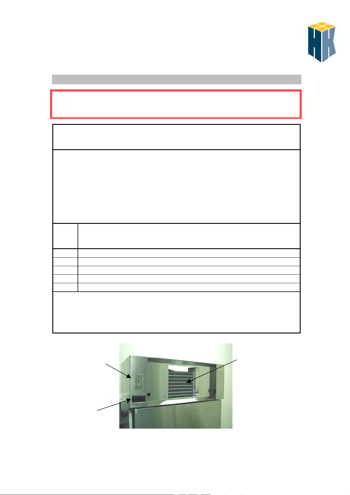
Cleaning the condenser
The condenser (pictured below) must be kept clean in order to maintain a
clear passage through which air may pass. Air is continually drawn through
the condenser fins, along with dust, lint, paper, grease, etc. Do not allow this
dirt to build up and block vision through the fins. A clean condenser will
minimise operating, maintenance and repair expenses.
The condenser fins are likely to require cleaning at least once a month but
the frequency will depend on unit usage and operating conditions.
Step Action
1 Isolate power and unplug the unit
2 Remove the protective grill from the front of the unit
3 Gently brush or vacuum the dirt from the condenser fins
4 Re-align the fins using a fin comb (H&K Ltd part number S06084)
5 Replace the cover panel
If there is a significant dirt build-up that is difficult to remove, contact a
refrigeration service company who will be able blow out the condenser with
pressurised air, CO
or nitrogen.
2
On/off
switch
Controller
Issue 1:1 31.10.2002
Condenser
fins
7
Page 8

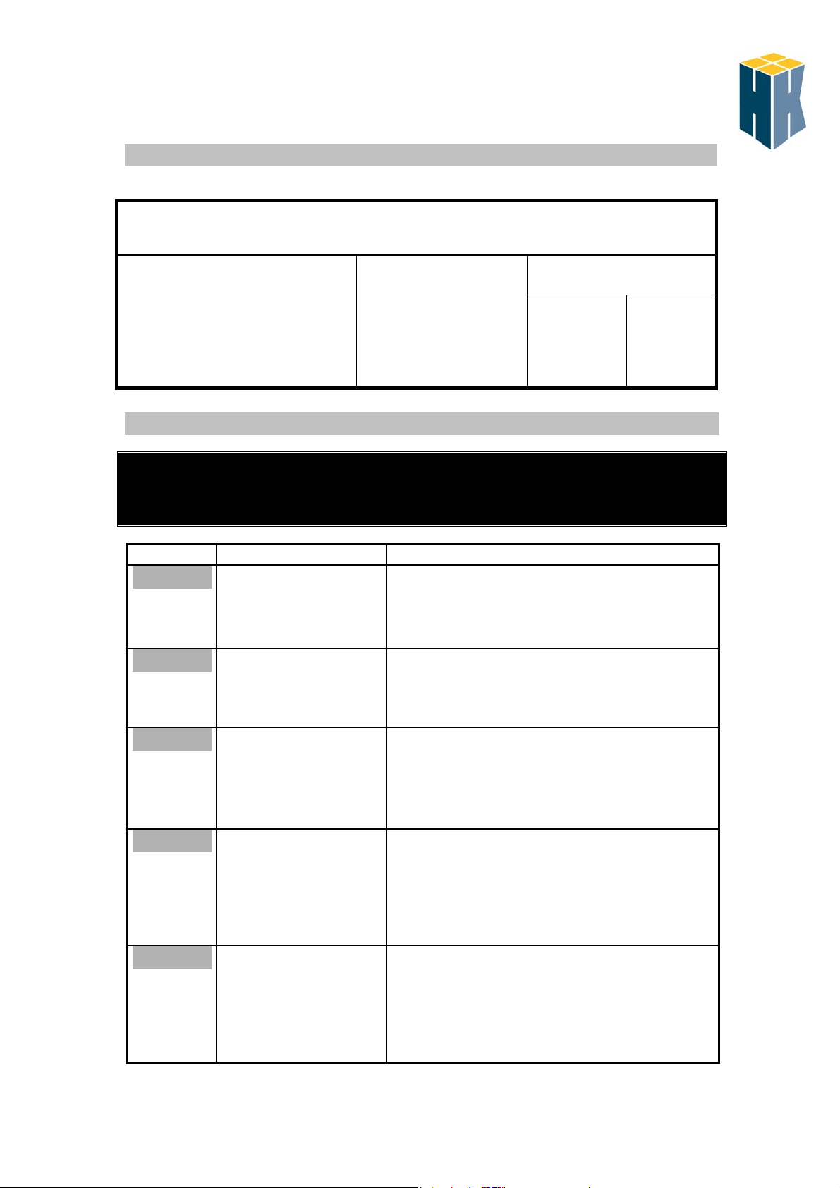
Troubleshooting
Problem Cause Repair
Unit will not start
Unit will not reach operating temperature
Issue 1:1 31.10.2002
1. Unit not plugged in
2. No power to unit
(controller display not
1. Plug unit into relevant
socket
2. Check store power supply
(isolator breaker tripped)
illuminated)
3. Unit still not operating
1. Loaded with product prior
to unit reaching operating
temperature. Product
loaded above -18°C.
2. Condenser fins dirty
3. Operating temperature
set point incorrect
4. Unit still not operating
3 Contact service company
1. Remove product until unit
has reached operating
temperature. Ensure
product is at correct
temperature prior to loading.
2. Clean fins (see
Maintenance)
3. Check controller setting
(see Setting operational
4. Contact service company
WARNING!
Electricity can kill
temperature)
Setting operational temperature MTR12
Setting the operating temperature of the unit
Unit must be switched on
Press
Filet Freezer Filet Chiller
Set
Adjust display
(¿ and À keys)
to read
-24 01
8
Page 9

Information for service company
LAE MTR12 controller configuration
Read following instructions fully before commencing any alterations
Set key
Display
Step Press Display
Programming the controller to the Filet Freezer and Chiller units
Commence with unit switched off
Adjust display
(¿ and À keys)
reads
Press Display
reads
Adjustment
to read
keys
Filet Freezer Filet Chiller
1 ¿ and À
simultaneously,
hold both and
switch unit on.
2 Set USP Set previous
3 Set ∩SP Set previous
4 Set RT1 Set previous
5 Set PF1 Set previous
6 Set ADJ Set previous
7 Set HY1 Set previous
8 Set - - - - -
On completion of the preceding steps the controller will adopt the new settings once the unit is
PAR -
-
-
-24
setting
(sets lowest
temperature)
-24
setting
(sets high point)
2
setting
(sets for delayed
start)
Off
setting
(switches off unit
if probe fails )
-4
setting
3
setting
switched off and then switched back on again.
(minimises
temperature
overshoot)
-
00
(sets lowest
temperature)
02
(sets high point)
2
(sets for delayed
start)
Off
(switches off unit
if probe fails )
00
2
(minimises
temperature
overshoot)
Issue 1:1 31.10.2002
9
Page 10

Read following instructions fully before commencing any alterations
Display
Set key
If before all of the proceeding steps are completed no key action is detected for 60 seconds
the controller will revert back to its running mode.
Step Press Display
1
2
¿ and À
simultaneously and
hold for approx. 4sec.
¿ and À
simultaneously
hold for approx. 4sec.
3 À key
4 À key
5 À key
6 À key
7 À key
8 À key
9 À key
10 À key
11 À key
12 À key
13 À key
On completion of the proceeding steps press ¿ and À keys simultaneously. The controller will
Issue 1:1 31.10.2002
FK 207T Controller configuration
Programming the controller
Commence with the unit switched on
Press Display
reads
PA
/ 1
/ 6
r0
r1
r2
c2
c7
c8
c9
d0
d3
d6
Set
Set
Set
Set
Set
Set
Set
Set
Set
Set
Set
Set
Set
adopt the new settings.
reads
0
previous
setting
previous
setting
previous
setting
previous
setting
previous
setting
previous
setting
previous
setting
previous
setting
previous
setting
previous
setting
previous
setting
previous
setting
Adjust display
(¿ and À keys)
to read
FREEZER UNIT
Adjustment keys
Adjust display
(¿ and À keys)
to read
-19
-32
CHILLER UNIT
-19
-32
0 0
3 2
-24 0
-24 2
2 2
90 90
100 100
1 1
0 0
0 0
1 1
10
Page 11
Setting the operating temperature FK207T
Press and hold Set key
Unit must be switched on
Adjust ¿ and Àkey
Fault codes FK207T
Adjustment
parameters
FREEZER
UNIT
-24°C
CHILLER
UNIT
01°C
This new controller has a fault indication program that aid’s in
recognising problem’s that may occur with the refrigeration aspects.
A simple code, listed below, will show on the controller display.
Code Reasons Remedies
E2
Corrupted
memory
data
E0
Cabinet
probe
alarm
E1
Evaporator
probe
alarm
COH
CSd
Issue 1:1 31.10.2002
• There is the
• Probe type incorrect
• Probe fault
• Probe type incorrect
• Probe fault
• The evaporator
• Condenser fins dirty
• The condenser
• Condenser fins dirty
• The condenser
corruption of the
configuration data of
the memory of the
instrument
temperature is
outside the limits of
the controller
temperature is
outside the limit set
within the parameter
C7
temperature is
outside the limit set
within the parameter
C8
• Switch off the power supply for 2minutes.
Reconnect the power supply; if error code still
displayed replace the unit.
• Fit correct probe type
• Check probe connections
• Fit correct probe type
• Check probe connections
• Test the temperature close to the probe to
ensure its between the set operating range
• Clean the condenser fins (see page 7)
• Check temperature close to the probe and
adjust parameter C7
• Clean the condenser (See page 7)
• Turn unit off
• Check temperature close to the probe and
adjust parameter C8
11
Page 12
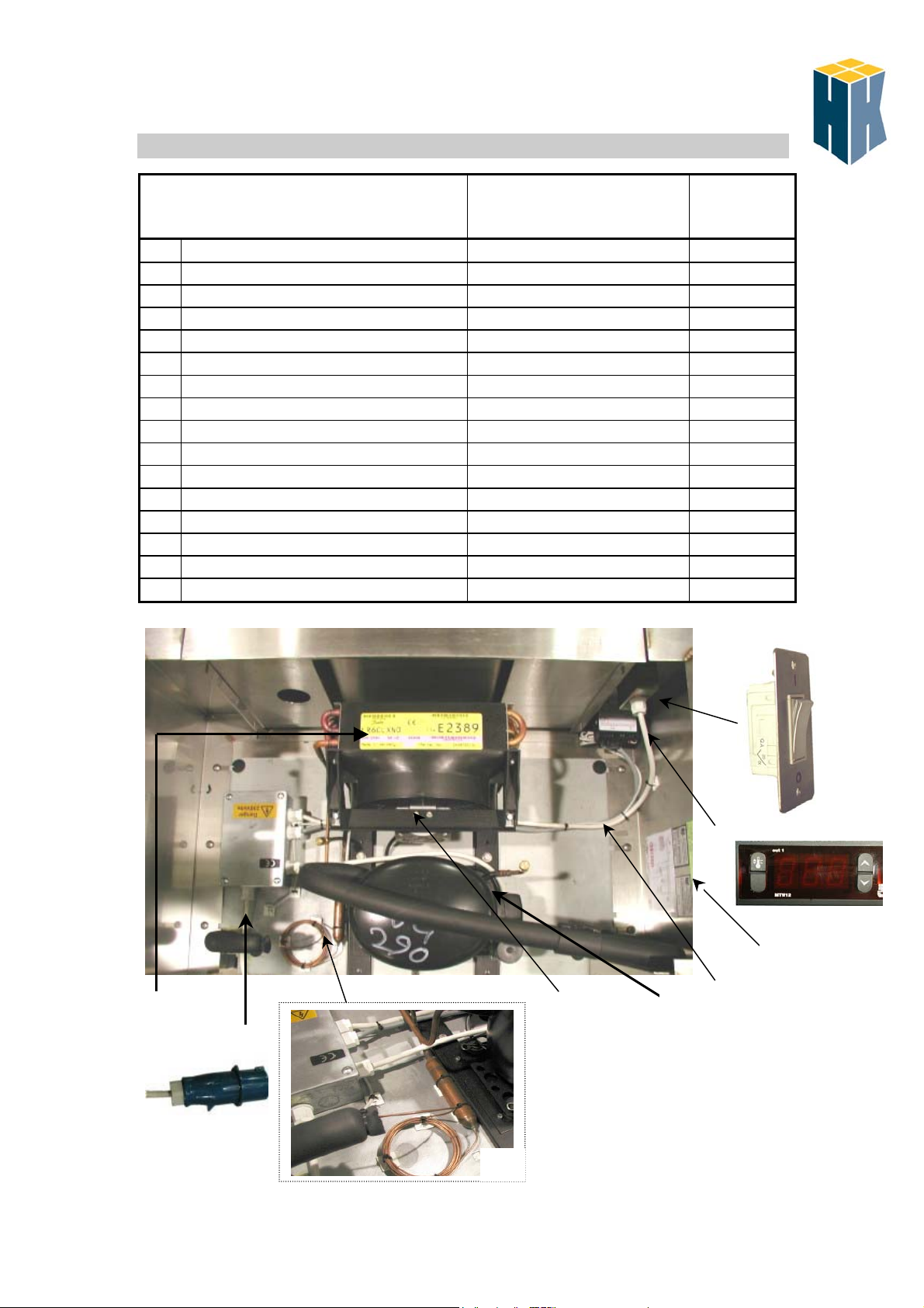
Description
On/off Switch E11020 1
1
LAE MTR12 Controller (Freezer) 1000-R02010 1
2
LAE MTR12 Controller (Chiller) 1002-R02010 1
2
Fk207T controller (Freezer) 1000-R02012 1
2
Fk207T controller (Chiller) 1001-R02012 1
2
Probe R02009 1
3
Compressor R01112 1
4
Capillary Tube and Drier R01201 1
5
Condenser Fan Motor R01020 1
6
Condenser Fan Blade R01021 1
7
Mains Cable E06126 3m
8
Plug E10021 1
9
Compressor assembly number - -
10
Quality and electrical numbers - -
11
Internal fan E20007 1
Door Gasket T03084 2
10
8 & 9
Replacement parts
Part number
6 & 7 4
5
Quantity
1
2
11
3
Issue 1:1 31.10.2002
12
Page 13
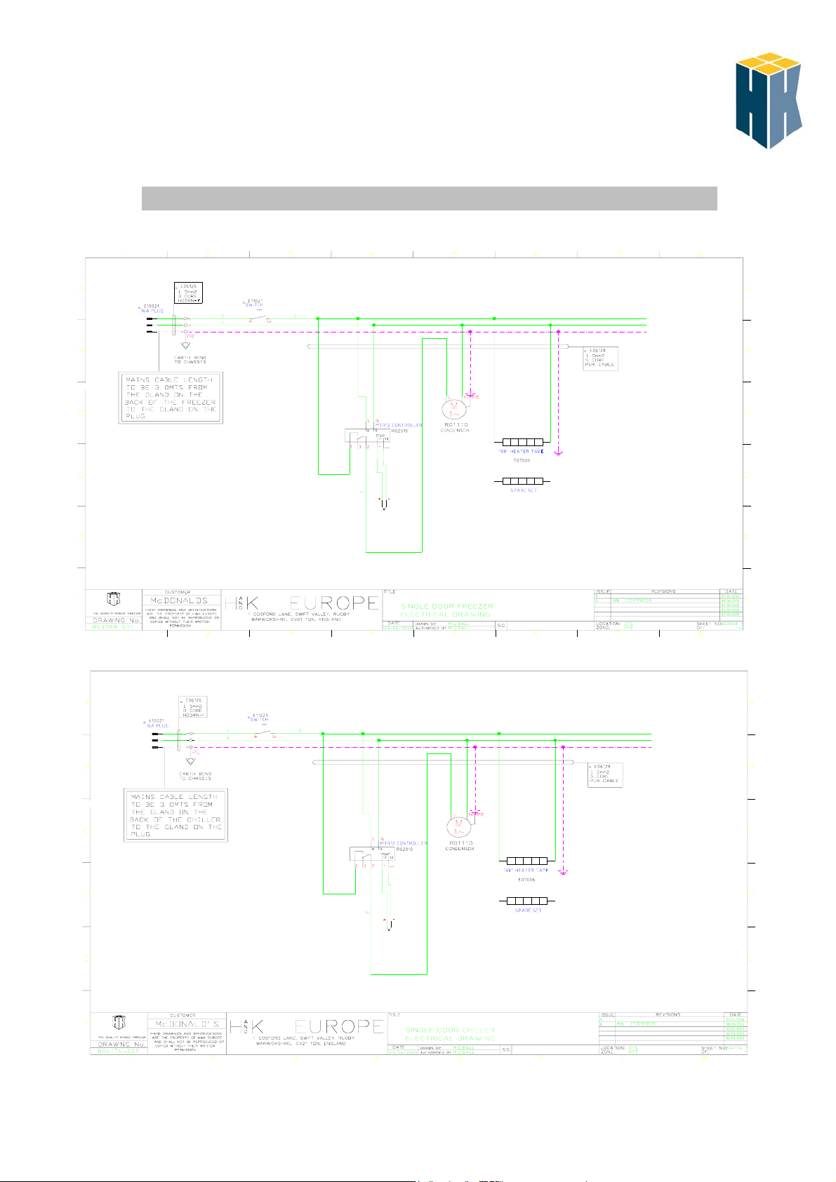
Freezer
Wiring schematic
Chiller
Issue 1:1 31.10.2002
13
 Loading...