

Page 1
All specifications and figures are subject to change without notice.
Page 2
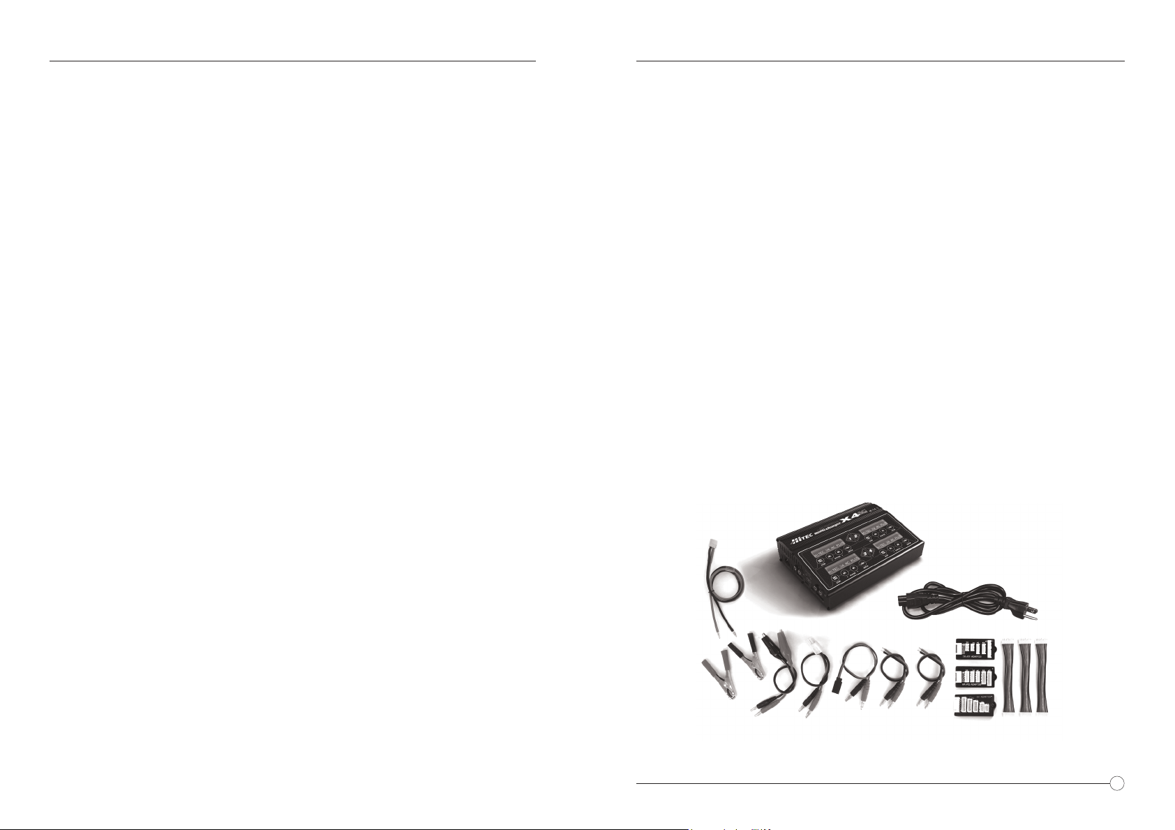
TABLE OF CONTENTS
INTRODUCTION
Introduction.…..…..…..…..…..…..…..…..…..…..…..…..…..…..…..….01
Charger Layout…..…..…..…..…..…..…..…..…..….…..…..…..…........03
Special Features…..…..…..…..…..…..…..…..…..….........................04
Warnings and Safety Information…..…..…..…..…..…..…..…..…..…..06
Default User Preferences Setup…..…..…..…..…..…..…..…..…..…...09
Connecting the Battery…..…..…..…..…..…..…..…..…..….................11
Program Flow Chart…..…..…..…..…..…..…..…..…..….....................12
Program Display Information…..…..…..…..…..…..…..…..…..…........13
Charging Lithium Chemistry (LiPo/LiIo/LiFe) Type Batteries............13
Discharging Lithium Chemistry (LiPo/LiIo/LiFe) Type Batteries........16
Charging/Discharging and Cycling NiCd or NiMH Batteries..............17
Congratulations on your purchase of the Hitec X4 AC Plus Multi-Charger. You are now the
owner of a compact multi chemistry battery charger with battery management and integral
Lithium battery balancing features. The X4 AC Plus features four totally independent and
identical 50 watt charging circuits for a total power of 200 watts. As a result, it can simultaneously charge or discharge up to 4 separate battery packs.
The X4 AX Plus can accept a variety of power inputs. The charger features a built in 22
Amp power supply powered by your standard 100-120 V AC household current or you can
attach it to a 12 Volt car battery or a 11 – 15 V (20 amp minimum) DC power supply.
The Hitec X4 AC Plus is simple to use, but the operation of a sophisticated automatic
charger such as the X4 AC Plus does require some knowledge and education by the user.
This instruction manual is designed to ensure that you can quickly become familiar with
the charger’s functions and capabilities. It is important that you read this instruction
manual in its entirety before attempting to use your new X4 AC Plus chargers.
Package Contents
1. Hitec X4 Plus
2. AC Input Cable
3. DC Input Cable
4. Battery Clamps
5. Alligator Clip Charging Connector
6. Tamiya Charging Connector
7. Receiver Battery Charging Connector
8. 2 x Bare Wire Connectors
9. 1 x TP/FP Type LiPo Balancer Board
10. 1 x HP/PQ Type LiPo Balancer Board
11. 1 x XH Type LiPo Balancer Board
Charging/Discharging Lead-Acid (Pb) Batteries...............................18
Battery Data Preset Storage and Load Feature…..…..…..…..…..…..20
Warning and Error Messages…..…..…..…..…..…..…..…..…..…........21
Recommended Accessories…..…..…..…..…..…..…..…..…..…..........22
Conformity and Regulatory Information…..…..…..…..…..…..…..…...22
Warranty and Servicing…..…..…..…..…..…..…..…..…..…................23
1
3
2
9
10
4
5
6
7
8
11
01
Page 3
INTRODUCTION
The Hitec X4 AC Plus allows you to charge up to four different batteries simultaneously.
The charger will automatically charge all 4 batteries at a time to their maximum capacity.
Additionally the batteries being charged do not need to have the same configuration or the
same chemistry. Therefore you can connect any one of a NiMH/NiCD/LiPo/LiFe battery
into any of the charging ports. This eliminates the time consuming efforts of charging all
your batteries separately.
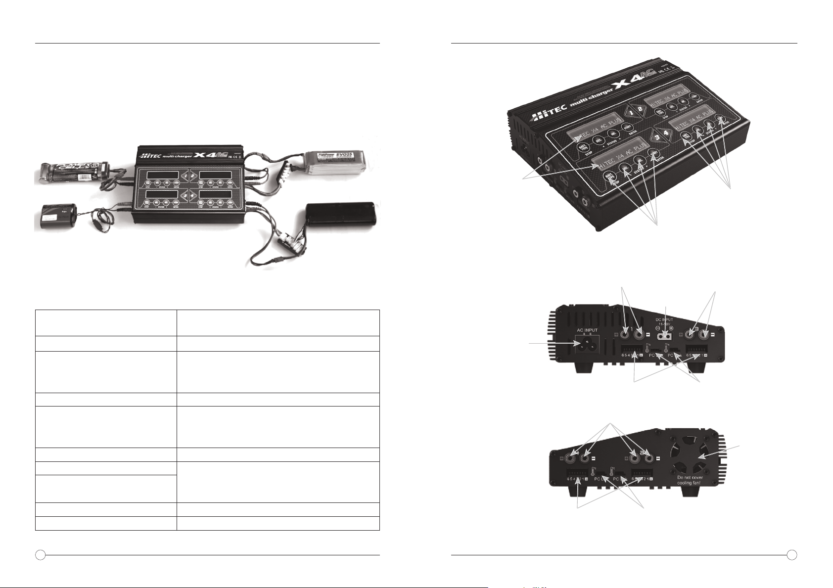
CHARGER LAYOUT
Specifications
Power Source
Operating Voltage Range
Charge Power
Discharger Power
Cell Count
Current Drain for Balancing Lithium
Charge Termination
NiCd/NiMH
Lead-Acid and Lithium
Dimensions
Net Weight
100-120V AC, 12V DC Car Battery or
11-15V DC Power Supply
DC 11 - 15 Volt
50 Watts, current is regulated accordingly
e.g. 11.1 V battery, charge current approx. 4.5 A
e.g. 22.2 V battery, charge current approx. 2.2 A
5 Watts, current is regulated accordingly
1-15 NiCd/NiMH cells
1-6 LiPo/LiIon/LiFe cells
1-10 Lead-Acid cells (2V - 20V)
300mA
Automatic, negative delta-peak method
Automatic, voltage-dependent, CC-CV process
8.9” x 6.7” x 2.6”
3.4 lbs.
LCD Screen
AC Input Power Port
100-120V AC
220-240V AC
(US Version)
(EU Version)
Universal Balancing
Port Pitch=2.54mm
Menu Control Buttons
Battery
Sockets
DC Input
Socket
Universal Balancing
Port Pitch=2.54mm
Battery Sockets
Temp. Sensor/PC Link
Available for 2 & 4 only output
Menu Control Buttons
Battery
Sockets
Temp. Sensor/PC Link
Available for 1 & 3 only output
Ventilation Fan
with Temperature
Sensor Control
02
03
Page 4

SPECIAL FEATURES
SPECIAL FEATURES
Optimized Operating Software
The software in X4 AC Plus automatically controls the current rate during the charging or
discharging process. This feature can prevent the user from overcharging their batteries
which could lead to damage or injury. If the charger detects a malfunction, the circuit
automatically disconnects and an alarm will sound, The operating functions of the X4 AC
Plus are controlled through a two-way communication link in order to maintain maximum
safety with minimal errors. All of these functions and settings are easily configured by the
user.
Internal Independent Lithium Battery Balancers
Each channel of the X4 AC Plus employs an individual-cell voltage balancer eliminating
the need for an external balancer for balance charging.
Balancing Individual Cells during Battery Discharging
During the process of discharging, the X4 AC Plus can monitor and balance each cell of
the lithium battery individually. If the voltage of any single cell is abnormal, an error
message will display and the discharge process will automatically end.
Charges Most Popular Lithium Batteries
The X4 AC Plus is compatible with the three most common Lithium chemistry batteries,
Li-Ion, LiPo and LiFe.
Multiple Lithium Battery Charge Modes
The X4 AC Plus’s programming allows for Fast Charge, Balance Charge or Storage
Charge Modes for LiPo, Li-Ion, and LiFe batteries.
• Fast Charge Mode: Reduces charging time, but does not balance the cells, this
mode only charges the battery to approximately 90% capacity.
• Balance Charge Mode: Monitors individual cell voltage, keeping the cells within an
acceptable voltage range and charges the pack to peak capacity.
• Storage Charge Mode: Used for long-term battery storage. Adjusts the voltage
level so the battery will not be damaged during long term storage.
Capacity and Processing Time Limit
The charging capacity is calculated as the charging current multiplied by time. If the
charging capacity exceeds the maximum limit set by the user, the process will terminate
automatically. Additionally the user can set the maximum amount of charging time. If the
charging time exceeds this limit, the process will terminate automatically.
Temperature Threshold*
The battery's internal chemical reaction causes the temperature of the battery to rise
during the charging process. If the temperature exceeds the limit, the charging process
will automatically terminate.
* This function is available by connecting an optional temperature probe, which is not
included in our package.
10 User Customizable Presets
The X4 AC Plus features 10 individually customizable presets so the user can store the
charge and discharge parameters for any particular battery type. These presets can be
recalled for the desired battery type without the need for any additional programming.
Cyclic Charging / Discharging
Batteries can be set to automatically Charge/Discharge or Discharge/Charge up to a
maximum of 5 cycles.
PC Based Analysis Using USB Communication*
The Hitec X4 AC Plus offers a PC-based program which can analyze the characteristics
of the battery via a USB port. It shows a graph of voltage, current and capacity curves. It
also displays the individual voltage of each cell in the lithium battery pack.
* Using optional PC-LINK USB Adapter (sold separately) and software that can be
downloaded from www.hitecrcd.com
Delta Peak Technology for Maximum Safety
The automatic charge termination program utilizes Delta-Peak voltage detection.
When the battery's voltage exceeds the threshold, the charge process is terminated
automatically.
Automatic Charging Current Limit
The maximum charge rate can be manually set when charging NiCd or NiMH batteries.
The X4 AC Plus will auto-detect when the batteries are fully charged and shut off, even
with low impedance NiMH packs.
04
05
Page 5
WARNINGS AND SAFETY INFORMATION
WARNING
FAILURE TO FOLLOW THESE IMPORTANT SAFETY NOTES OR THE INSTRUCTION
MANUAL CAN RESULT IN SEVERE INJURY, PROPERTY DAMAGE OR LOSS OF LIFE.
Please read this entire instruction manual completely and attentively before using
this product, as it covers a wide range of information on operation and safety.
Never leave the charger unattended when it is connected to its power supply. If any
malfunction is found, TERMINATE THE PROCESS AT ONCE and refer to the
instruction manual.
Keep the charger away from dust, moisture, water, excessive heat, direct sunlight
and vibration.
The maximum allowable input voltage is 120 VAC when using the supplied AC power
cord or 15V DC when using an external DC power source.
The charger and the battery should be put on a heat-resistant, non-flammable and
non-conductive surface. Never place them on a car seat, carpet or other flammable
surface. Keep all flammable volatile materials away from the operating area.
WARNINGS AND SAFETY INFORMATION
Before you Start Charging or Discharging your Batteries Consider the
Following
• Did you select the appropriate program suitable for the type of battery you are charging?
• Did you set up adequate current for charging or discharging?
• Have you checked the battery voltage? Lithium battery packs can be wired in parallel
and in series, i.e. a 2-cell pack can be 3.7V (in parallel) or 7.4V (in series).
• Have you checked that all connections are firm and secure? Make sure there are no
intermittent contacts at any point in the circuit.
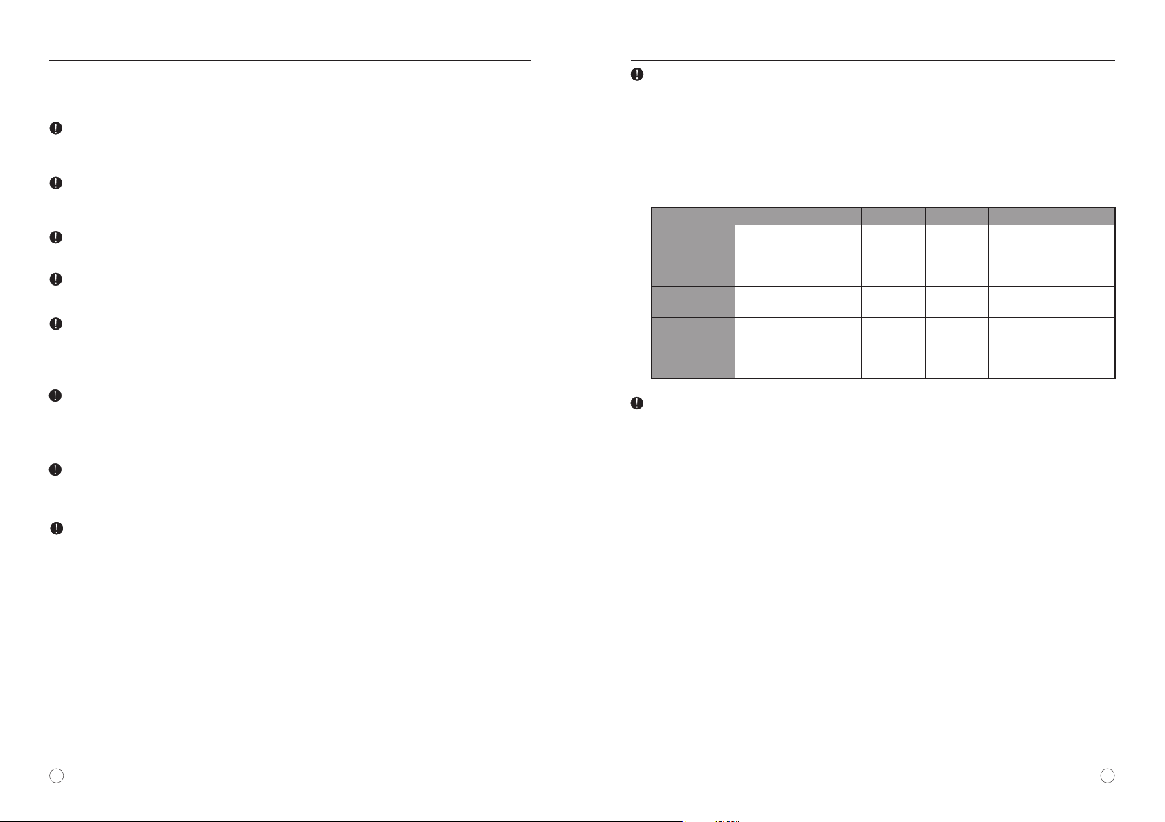
Standard Battery Parameters
Pb
2.0V /c ell
2.46 V/ cell
n/a
≦0.4C
≧1.75V/cell
Nominal
Volt ag e
Max Charge
Volt age
Storage
Volt ag e
Allowable
Fast Charge
Min. Discharge
Voltage
LiPo
3.7V /c ell
4.2V /c ell
3.8V /c ell
≦1C
≧3.0V /c ell
LiIo n
3.6V /c ell
4.1V /c ell
3.7V /c ell
≦1C
≧2.5V /c ell
LiFe
3.3V /c ell
3.6V /c ell
3.3V /c ell
≦4C
≧2.0V /c ell
NiCd
1.2V /c ell
1.5V /c ell
n/a
1C-2 C
≧0.85V/cell
MiMH
1.2V /c ell
1.5V /c ell
n/a
1C-2 C
≧1.0V /c ell
Make sure you know the specifications of the battery you are charging or discharging
to ensure it meets the requirements of this charger. If the program is set up incorrectly, the battery and charger may be damaged. Fire or explosion can occur due to
overcharging.
To avoid short circuiting between the charge lead, always connect the charge
cable to the charger first, then connect the battery. Reverse the sequence when
disconnecting.
Never Attempt to Charge or Discharge the Following Types of
Batteries
• A battery pack which consists of different types of cells
(including different manufacturers)
• A battery that is already fully charged or just slightly discharged
• Non-rechargeable batteries (they pose an explosion hazard)
• Batteries that require a different charge technique from NiCd, NiMH, LiPo
or gel cell (Pb, lead-acid battery)
• A faulty or damaged battery
• A battery fitted with an integral charge circuit or a protection circuit
• Batteries installed in a device or which are electrically linked to other
components
• Batteries that are not expressly stated by the manufacturer to be suitable for
the currents the charger delivers during the charge process
06
Charging
During the charge process, a specific quantity of electrical energy is fed into the battery.
The charge quantity is calculated by multiplying charge current by charge time. The
maximum permissible charge current varies depending on the battery type or its performance, and can be found in the information provided by the battery manufacturer. Only
batteries that are expressly stated to be capable of quick charge should be charged at
rates higher than the standard charge current.
Connect the battery to the terminal of the charger. Red is positive and black is negative.
In the event there is any significant resistance in the battery cable and/or connector, the
charger will not be able to properly detect the resistance of the battery pack resulting in
an error. It is essential in order for the charger to operate properly that the battery charge
leads should be of adequate quality for the size of the battery.
Always refer to the manual by the battery manufacturer pertaining to charging methods.
Operate according to their recommended charging current and charging time. Lithium
batteries, in particular, should be charged strictly according to the manufacturer's
instruction.
Pay close attention to the connection of lithium batteries.
Do not attempt to disassemble the battery pack.
Please take note that lithium battery packs can be wired in parallel and in series. In the
parallel connection, the battery’s capacity is calculated by multiplying the single battery’s
capacity by the number of cells, bearing in mind that total voltage stays the same. If the
voltage is imbalanced, it may cause a fire or explosion. Lithium batteries are always
recommended to be charge in series.
07
Page 6

WARNINGS AND SAFETY INFORMATION
DEFAULT USER PREFERENCES SETUP
Discharging
The main purpose of discharging a battery is to clean the residual capacity of the
battery or to reduce the battery’s voltage to a defined level. It is critical that the same
attention be paid to the discharging process as to the charging process. The final
discharge voltage should be set correctly to avoid deep discharging. Lithium batteries
cannot be discharged to voltage lower than the minimum voltage for the cell type.
Doing so will result in a rapid loss of capacity and/or total failure. Generally, lithium
batteries don’t need to be discharged and it is not recommended. If you choose to
discharge your lithium batteries make sure to pay attention to the minimum voltage
setting.
Some rechargeable batteries have a memory effect. If they are partly used and
recharged before the complete charge/discharge cycle is accomplished, they
remember this and will only use that part of their capacity next time. It is generally
known that NiCd and NiMH batteries suffer from this memory effect.
NOTICE
THIS CHARGER WAS DESIGNED AND APPROVED EXCLUSIVELY FOR USE WITH
THE TYPES OF BATTERIES STATED IN THIS INSTRUCTION MANUAL. HITEC RCD
USA ACCEPTS NO LIABILITY OF ANY KIND IF THE CHARGER IS USED FOR ANY
PURPOSE OTHER THAN THAT STATED. SINCE WE ARE UNABLE TO ASSURE
THAT THE USER WILL PROPERLY FOLLOW THE SUPPLIED INSTRUCTIONS AND
HAVE NO CONTROL OVER ONE'S PROPER USE OR MAINTENANCE OF THE
DEVICE, WE ARE OBLIGATED TO DENY ANY AND ALL CLAIMS OF LIABILITY FOR
LOSS, DAMAGE OR INJURY WHICH ARE INCURRED DUE TO IMPROPER USE AND
OPERATION OF THIS PRODUCT. UNLESS OTHERWISE PRESCRIBED BY LAW,
THE LIMIT OF OUR LIABILITY SHALL NOT EXCEED THE INVOICE VALUE OF THE
CHARGER.
POWERING THE CHARGER
The Hitec X4 AC Plus comes with a built in switching power supply allowing you to
connect it directly to a 120 VAC wall socket using the supplied AC power cord. The
charger can also be powered by a 12VDC car battery using the included large terminal
clips with matching 4mm female bullet connectors or it can be connected directly to a DC
power supply. When connecting to a battery or power supply it is critically important that
you use either a fully charged 12 volt car battery or a high quality DC power supply that
has a voltage range between 12V to 15V DC and a minimum current rating of 20A.
Failure to use proper input power can result in unreliable performance and may damage
the charger.
4mm bullet
connectors
plug directly
into most power
supplies.
Using terminal
clip attaching
to car battery.
When powered on for the first time the X4 AC Plus will load a set of default parameters
most commonly used by most users. The screen displays the information in the following
sequence. The user can customize the parameters on each screen to suit their own
preferences.
To change the parameter values in the program, press the Start/Enter key to choose the
parameter you want to change. Once the parameter is blinking you can change the value
with the INC (up/forward) or DEC (down/back) keys. The value will be stored by pressing
the Start/Enter key once and the blinking stops.
WARNING
DO NOT CONNECT A BATTERY TO THE CHARGER BEFORE SETTING
UP THE DEFAULT USER PREFERENCES
Main User Setup Screen
The first screen displayed is the Lithium battery set-up screen, you
can press ENTER to bypass this screen and go to the next user
ENTER
setup screen, or you can set the default Lithium battery type before
moving on.
The Lithium Battery Select Screen
Here you can choose one of the three kinds of Lithium batteries
supported by the X4 AC Plus, LiFe (3.3V), Lilo (3.6V) or LiPo (3.7V).
DEC INC
If you plan to use one type of Lithium chemistry battery you can set
the default here. WARNING: Make sure when you connect your
battery that you have selected the proper type of battery before you
begin charging your battery. Once you have established the desired
settings press Start/Enter to confirm the setting then press INC to
DEC INC
move on to the next parameter.
LiPo /LiIo/LiFe Check Time
To avoid an erroneous setting by the user the X4 AC Plus will
automatically detect the cell count of a Lithium battery at the beginning of the charge or discharge process. To prevent an overdischarged battery from being detected incorrectly, resulting in an
error, you can set a time limit for the processor to verify the cell
count. The default setting is 10 minutes which is typically enough
time to properly detect the cell count. It is not recommended that you
change this setting as setting to long of a “Check Time” can produce
dangerous results. Once you have established the desired settings
press Start/Enter to confirm the setting then press INC to move on
to the next parameter.
DEC INC
08
09
Page 7

DEFAULT USER PREFERENCES SETUP
DEFAULT USER PREFERENCES SETUP
DEC INC
10
DEC INC
DEC INC
DEC INC
DEC INC
DEC INC
DEC INC
DEC INCDEC INC
DEC INCDEC INC
DEC INCDEC INC
NiMh & NiCd Delta Peak Sensitivity Setting
This feature sets the cutoff voltage for the automatic charge
termination of a NiMH and NiCd battery pack. The setting can
range from 5 to 20mV per cell, the default is 12mV for NiCd
batteries and 7mV for NiMH, the parameters are set individually
for NiCd and NiMh batteries. If the cutoff voltage is too high,
there is a danger of overcharging the battery, if it is too low there
is a possibility of premature charge termination. Refer to the
battery manufacturer’s specifications to determine the proper
setting. Once you have established the desired settings press
Start/Enter to confirm the setting then press INC to move on to
the next parameter.
Temperature Cutoff Setting
You can choose whether or not you want to use the automatic
temperature cut off when using the optional temperature
sensors. When turned on you can set the maximum temperature
at which the charger should allow the battery to reach during
charging. Once a battery reaches this temperature, the charge
or discharge process will be terminated to protect the battery.
Once you have established the desired settings press
Start/Enter to confirm the setting then press INC to move on to
the next parameter.
Waste Time Setting
When charge/discharge cycling a battery the battery will become
warm. You can set a time delay ranging from 0 to 60 minutes
after each charge/discharge process to allow the battery to cool
down before starting the next charge/discharge cycle. Once you
have established the desired settings press Start/Enter to
confirm the setting then press INC to move on to the next
parameter.
Safety Timer Setting
When the charge process starts, the integrated safety timer runs
simultaneously. If an error occurs or the charge termination
circuit cannot detect if the battery is fully charged, this setting will
terminate the charge process to prevent overcharging. Use the
Safety Timer Calculation below to determine the proper setting.
Safety Timer Setting Calculation
To determine the correct safety time setting when charging NiCd
or NiMH batteries, divide the capacity by the current, and then
divide the result by 11.9. Set the results of this calculation as the
number of minutes for the safety timer setting. If the charger
stops at this time threshold, about 140% of the capacity will have
been fed into the battery. Example: 2000mAh 2.0A
(2000/2.0=1000)/11.9=84 minutes.
Capacity Cutoff Setting
The charging software allows the user to create a maximum
charge capacity protection setting. If the delta-peak voltage is not
DEC INC DEC INC
properly detected or the safety timer times out, the charge process
will stop automatically when the battery reaches the set maximum
charge capacity set by the user. Once you have established the
desired settings press Start/Enter to confirm the setting then press
DEC INC
INC to move on to the next parameter.
Sound Settings (Key & Buzzer Mute)
A beep sounds to confirm the every time the user presses a button,
additionally a sound is emitted during the operation of the charger
DEC INC
to confirm a different mode change. These functions can be
switched on or off. Once you have established the desired settings
press Start/Enter to confirm the setting then press INC to move on
DEC INC
to the next parameter.
Low Input Voltage Setting
This function monitors the input voltage of the DC power source
used to power the charger. If the voltage is lower than the user
setting, the program will end forcibly to protect the input source.
Once you have established the desired settings press Start/Enter
to confirm the setting. You have now set the initial user settings.
You can repeat this procedure for the other Channels.
CONNECTING THE BATTERY
WARNING
Before connecting a battery, it is absolutely essential to check that you have set the
parameters correctly. If the settings are incorrect, you can damage the battery and create
a dangerous situation that could result in serious damage or injury.
Connecting the Battery
To avoid creating a short circuit between the banana plugs always connect the charge
leads to the charger first, and then to the battery. Reverse the sequence when disconnecting the pack.
Connecting the Balancer Socket
These pictures show the correct way
to connect your battery to the Hitec
X4 AC Plus for charging in the
balance mode. The balance socket
attached to the battery must be
connected to the charger with the
black wire aligned with the negative
marking. If your battery’s balancer
socket does not fit in the socket
make sure to use the proper adapter
board for you battery type.
123456
S1
+
S2
+
S3
+
11
Page 8

PROGRAM FLOW CHART
PROGRAM DISPLAY INFORMATION
You can view a variety of information on the LCD screen during the charge and
discharge process. Press the DEC key to display and scroll through these settings.
When connected to the balancing port you can monitor the voltage of each individual
cell by pressing the INC key.
When the program is completed, the final voltage is displayed.
DEC
When the capacity cutoff function is turned on, the capacity value is
displayed.
DEC
When the safety timer is displayed, the duration of time in minutes is
displayed.
DEC
This screen shows that the temperature cutoff function is turned on.
DEC
When the temperature probe is used, the external temperature will
be displayed.
DEC
This shows the present input voltage going to the charger.
DEC
12
When the battery is connected to the balancing port, you can check
the voltage of each cell in the battery pack. The program can display
the voltages of up to 6 batteries.
CHARGING LITHIUM CHEMISTRY (LiPo/Lilo/LiFe) TYPE BATTERIES
NOTICE
This program is only suitable for charging/discharging Lithium chemistry batteries. The
X4 AC Plus was designed to only charge three kinds of Lithium batteries, Lithium Ferrite
(LiFe), Lithium Ion (LiIo) and Lithium Polymer (LiPo). It is very important that you determine the type of battery you are charging and set the charging parameters correctly. It is
important that the nominal voltage, final voltage, and battery capacity be properly set for
desired operation. Please refer to the following information regarding the different types
of Lithium chemistry batteries.
13
Page 9

CHARGING LITHIUM CHEMISTRY (LiPo/Lilo/LiFe) TYPE BATTERIES
Lithium Ion (Li-Ion)
Nominal Voltage Level: 3.6V per cell
Max. Charge Voltage: 4.1V per cell
Allowable Fast Charge Current: 1C or less
Min. Discharge Voltage Cut Off Level: 2.5V per cell or higher
Lithium Polymer (Li-Po)
Nominal Voltage Level: 3.7V per cell
Max. Charge Voltage: 4.2V per cell
Allowable Fast Charge Current: 1C or less
Discharge Voltage Cut Off Level: 3.0V per cell or higher
Lithium Ferrite (LiFe)
Nominal Voltage Level: 3.3V per cell
Maximum Charge Voltage: 3.6V per cell
Allowable Fast Charge Current: 4C or less
Discharge Voltage Cut Off Level: 2.0V per cell or higher
NOTE
When you want to change the settings, press the START/ENTER key to make it blink,
then use the DEC or INC key to change the setting. Then press the START/ENTER key
again to store the setting.
Charging Lithium Battery in the Charge Mode
These methods for charging LiPo/Li-Ion/LiFe batteries without a balance lead.
The first line on the left side of this screen shows the type of
battery chosen. The second line shows the user set current
on the left and the user set voltage on the rights. After setting
DEC INC DEC INC
Batt Type
Number
of Cells
14
Stop
Charging
Time
Start
Enter
Start
Enter
Battery
Voltage
Charging
Current
‘>3 seconds’
the current and voltage, press the START/ENTER key for
more than 3 seconds to start the process (charge current
range: 0.1-6.0A, voltage range: 3.7-22.2V).
The next display shows the number of cells you set up as ”S”
and the number of cells the processor detects as “R”. If both
numbers are identical, you can start charging by pressing the
START/ENTER button. If not, press the BATT TYPE/STOP
button to go back to the previous screen to carefully check the
number of cells of the battery pack before proceeding.
This next screen shows the real-time status during the charge
process. Press the BATT TYPE/STOP key once to stop the
charge process.
Charged
Capacity
CHARGING LITHIUM CHEMISTRY (LiPo/Lilo/LiFe) TYPE BATTERIES
Charging Lithium Battery in Balance Mode
This function is for balancing the voltage of Lithium-polymer battery cells individually
while charging. In the balance mode, the battery needs to have a balance lead to connect
to the balance port at the right side of the charger and the battery's power leads to the
output of the charger. Charging in this mode is different from the normal modes because
the built-in processor monitors the voltage of each individual cell and controls the input
current fed into each cell in order to equalize the voltage.
The first line on the left side of this screen shows the type of
battery chosen. The second line shows the user set current
on the left and the user set voltage on the rights. After setting
DEC INC DEC INC
Batt Type
Number
of Cells
Stop
Charging
Time
Start
Enter
Start
Enter
Battery
Voltage
Charging
Current
‘>3 seconds’
Charging Lithium Batteries in Fast Mode
When charging lithium chemistry batteries in the fast charge mode the charging current
will become lower towards the end of the charge cycle. In fast mode the charging capacity is slightly lower than in normal charge mode, but charging time is reduced.
DEC INC DEC INC
Batt Type
Number
of Cells
Stop
Charging
Time
Start
Enter
Start
Enter
Battery
Voltage
Charging
Current
‘>3 seconds’
the current and voltage, press the START/ENTER key for
more than 3 seconds to start the process (charge current
range: 0.1-6.0A, voltage range: 3.7-22.2V).
The next display shows the number of cells you set up as ”R”
and the number of cells the processor detects as “S”. If both
numbers are identical, you can start charging by pressing the
START/ENTER button. If not, press the BATT TYPE/STOP
button to go back to the previous screen to carefully check the
number of cells of the battery pack before proceeding.
This next screen shows the real-time status during the charge
process. Press the BATT TYPE/STOP key once to stop the
charge process.
Charged
Capacity
The first line on the left side of this screen shows the type of
battery chosen. The second line shows the user set current
on the left and the user set voltage on the rights. After setting
the current and voltage, press the START/ENTER key for
more than 3 seconds to start the process (charge current
range: 0.1-6.0A, voltage range: 3.7-22.2V).
The next display shows the number of cells you set up as ”R”
and the number of cells the processor detects as “S”. If both
numbers are identical, you can start charging by pressing the
START/ENTER button. If not, press the BATT TYPE/STOP
button to go back to the previous screen to carefully check the
number of cells of the battery pack before proceeding.
This next screen shows the real-time status during the charge
process. Press the BATT TYPE/STOP key once to stop the
charge process.
Charged
Capacity
15
Page 10

CHARGING LITHIUM CHEMISTRY (LiPo/Lilo/LiFe) TYPE BATTERIES
DISCHARGING LITHIUM CHEMISTRY (LiPo/Lilo/LiFe) TYPE BATTERIES
NOTE
During the discharge process the X4 AC Plus’s Microprocessor monitors the voltage of
each cell during the Storage Mode or Discharge process. If the voltage of any cell is
abnormal, the charger will display an error message and immediately terminate the
program. Before disconnecting the battery review the error message then press the INC
button to display which cell is.
Charging Lithium Batteries in the Storage Mode
The Storage Mode function is for charging/discharging batteries that will not be used
immediately or that will be stored for a period of time. The program is designed for charging or discharging batteries to a specific voltage level depending on the type of battery
(Li-ion = 3.75V, LiPo = 3.85V and LiFe = 3.3V) The program will begin to discharge if the
original state of the battery exceeds the voltage level for storage.
This screen, you can set up the current and voltage of the
battery pack. Charging and discharging will bring the batteries to the storage level.
DEC INC DEC INC
Batt Type
Stop
Start
Enter
‘>3 seconds’
This screen shows the real-time status of the charge or
discharge process. Press the BATT TYPE/STOP key once to
stop the charging process.
Elapsed
Time
Charge or
Discarge
Current
Supplied
Capacity
Battery
Voltage
Number
of Cells
Error Message Display
This screen shows that the processor detected the voltage of
one on the cells is too low.
INC
This screen shows the 4th cell was damaged. If the cell is
disconnected or not present the reading of the voltage will be
zero.
DISCHARGING LITHIUM CHEMISTRY (LiPo/Lilo/LiFe) TYPE BATTERIES
Lithium batteries are recommended to be discharged partially rather than fully. Frequent
full discharging should be avoided if at all possible. Instead, charge the battery more often
or use a battery of larger capacity. Full capacity cannot be reached until it has been
subjected to 10 or more charge cycles. The cyclic process of charge and discharge will
optimize the capacity of the battery pack.
16
The setting of the discharge current on the left cannot exceed
1C, and the setting on the right cannot be under the voltage
recommended by the manufacturer to avoid deep discharg-
DEC INC DEC INC
Batt Type
Stop
Start
Enter
‘>3 seconds’
ing. Press the START/ENTER key for more than 3 seconds to
start discharging.
This shows the real-time status of discharging; you can press
the BATT TYPE/STOP key to stop discharging.
Number
of Cells
Elapsed
Time
Battery
Voltage
Discharge
Current
Discharged
Capacity
Error Message Display
This screen shows that the processor detected the voltage of
one on the cells is too low.
INC
This screen shows the 4th cell was damaged. If the cell is
disconnected or not present the reading of the voltage will be
zero.
CHARGING/ DISCHARGING AND CYCLING NiCd OR NiMh BATTERIES
There are two methods of charging NiCD and NiMh batteries, Manual or Auto Mode. When
in the NiMh or NiCd Program Select screen you can change modes by pressing the
START/ENTER key until the current field begins flashing then press INC and DEC simultaneously to switch between Auto and Manual Mode. using the charge current you set up. In
the “auto” mode, you should set the upper limit of the charge current to avoid damage caused
by excessive charge current. This is especially important for low quality batteries that have
low resistance and capacity. In the “manual mode” the charger will only charge at the current
you set. Note the following charger / discharge specifications for NiCd and NiMh Batteries.
Nominal Voltage level: 1.2V/cell
Allowable Fast Charge Current: 1C-2C (depends on performance of cell)
Discharge Voltage Cut Off Level NiCd: 0.85V per cell
Discharge Voltage Cut Off Level NiMh: 1.0V per cell
Charging NiCd or NiMh Batteries
This program is for charging NiCd/NiMH batteries typically
used in an R/C model application. Press the START/ENTER
key until the parameter you want to change begins to blink
DEC INC DEC INC
Batt Type
Battery
Type
Stop
Elapsed
Time
Start
Enter
Charge
Current
‘>3 seconds’
Battery
Voltage
then use the INC or DEC keys to change the value. Press the
START/ENTER key to store the setting.
This screen shows the real-time status of charging. You can
press the BATT TYPE/STOP key to stop the charge process.
Charged
Capacity
17
Page 11

CHARGING/ DISCHARGING AND CYCLING NiCd OR NiMh BATTERIES
Discharging NiCd or NiMh Batteries
Set the discharge current on the left and the voltage cutoff on
the right by pressing the START/ENTER key for more than 3
seconds to start the program. Discharge current can be set
DEC INC
Batt Type
Stop
DEC INC
Start
Enter
from 0.1-1.0A and voltage cutoff from 0.1-25.0V.
‘>3 seconds’
This screen indicates the discharging state. You can press the
START/ENTER key to alter the discharge current. Press the
START/ENTER key again to store the setting. Press the BATT
TYPE/STOP key to stop discharging. The charger will emit a
Elapsed
Battery
Type
Time
Discharge
Current
Discharged
Capacity
sound to indicate the end of the discharge process.
Battery
Voltage
Charge/Discharge Cycling Of NiCd/NiMh Batteries
Set the cycle sequence on the left and the number of cycles on
the right. The battery can be cycled 1-5 cycles.
DEC INCDEC INC
Battery
Type
Batt Type
Stop
Elapsed
Time
Discharge
or Charge
Current
Start
Enter
Battery
Voltage
‘>3 seconds’
Press the BATT TYPE/STOP key to stop the program then
press the START/ENTER key to alter the charge or discharge
current. A sound will indicate the end of the program.
Discharged
or Charged
Capacity
When the charger approaches the end of the program cycle,
you can view the capacity of the battery being charged or
discharged. Use the INC or DEC keys to scroll through the
results of each cycle.
CHARGING / DISCHARGING LEAD-ACID (PB) BATTERIES
This program is only suitable for charging a lead-acid (PB) type battery with a nominal
voltage range of 2 to 20 volts. Lead acid (Pb) batteries can only deliver current lower in
comparison to their capacity. The same restriction applies to the charging process.
Consequently, the optimum charge current for lead acid (Pb) batteries is only 1/10 of its
rated capacity. You cannot fast charge lead acid (Pb) batteries. Please refer to the
following specification regarding charging and discharging lead acid (Pb) batteries.
Nominal Voltage Level: 2.0V per cell
Maximum Charge Voltage: 2.46V per cell
Allowable Charge Current: 0.4C or less
Discharge Voltage Cut Off Level: 1.75V or higher per cell
.
18
CHARGING / DISCHARGING LEAD-ACID (PB) BATTERIES
Batt Type
Stop
Elapsed
Time
Batt Type
Stop
Elapsed
Time
DEC INCDEC INC
Start
Enter
Battery
Voltage
Charge
Current
DEC INCDEC INC
Start
Enter
Battery
Voltage
Discharge
Current
‘>3 seconds’
Charged
Capacity
‘>3 seconds’
Discharged
Capacity
Set the charge current on the left and the nominal voltage on
the right. Charge current can be set from 0.1-6.0A. The voltage
must match the battery being charged. Press the
START/ENTER key for more than 3 seconds to start charging.
The screen will display the real-time charging status. Press the
START/ENTER key to alter the charge current. Press the
START/ENTER key again to store the parameter settings you
set. Press the BATT TYPE/STOP key to end the program.
Set up the discharge current on the left and the nominal
voltage on the right. The discharge current can be set from
0.1-1.0A. The voltage should match the battery being
charged. Press the START/ENTER key for more than 3
seconds to start discharging.
The screen displays the real-time discharging status. Press
the Start/Enter key to alter the discharge current. Press the
Start/Enter key again to store the parameter value you set.
Press the BATT TYPE/STOP key to end the program.
19
NOTICE
Due to the chemistry characteristic of a Pb battery, the cut-off point may be difficult to
detect at times. We recommend you use the CAPACITY CUT-OFF feature to protect the
battery. Refer to the Default User Preferences Setup section of this manual to set up
this feature.
Charging Lead Acid (Pb) Batteries
Battery
Type
Discharging Lead Acid (Pb) Batteries
Battery
Type
Page 12

BATTERY DATA PRESET STORAGE AND LOAD FEATURE
For your convenience, the X4 AC Plus has a data storage and load program that can
store up to five preset battery charge or discharge configurations. You can recall these
settings when charging or discharging without having to setup the program again. To
get to the save data screen press the BATT. TYPE/ STOP button until you see the
Save Data screen. Press the START/ENTER key to modify the menu, and use the INC
or DEC to change the parameters.
WARNING AND ERROR MESSAGES
The X4 AC Plus incorporates a variety of systems to verify the various
charge/discharge processes and the overall state of the electronics. In case of an error,
the charger will emit an audible alarm and the screen will display the cause of the error.
See the following description of the errors and their possible causes.
Save Data Program
Setting of the parameters in the first screen will not affect the
charge and discharge process. It is only for identifying the
Start
Enter
specification of the battery you will create a preset for. In this
example it is a NiMH battery pack with 12 cells and a capacity
of 3000mAh. When you have completed this process press
Voltage
Batt Type
Stop
Data
Number
Capacity
Start
Enter
Type of
Battery
‘>3se conds ’
charge/discharge setup screen.
Set up the charge current in the manual mode, or the current
and hold the START/ENTER key for 3 seconds to enter the
limit in the auto mode. Press the INC and DEC key simultaneously to make the current field blink to switch the charge
DEC INC DEC INC
mode.
Set up the discharge current and cutoff voltage.
DEC INC DEC INC
DEC INC
Set up the charge/ discharge sequence and cycle number.
DEC INC DEC INC
Start
Enter
‘>3seconds’
Once you have completed the setup procedures press and
hold the START/ENTER key for 3 seconds to save the data.
Load Data Program
This program is designed to load the data stored in the “save data” program. To get to
the save data screen press the BATT. TYPE/ STOP button until you see the Load Data
screen Press the START/ENTER key to make the data field blink and press the INC or
DEC keys for at least 3 seconds to load the data.
Incorrect polarity connected.
Battery connection is interrupted.
Short circuit on the battery connection.
Incorrect input voltage.
The voltage of the battery pack has been incorrectly set.
The charger has malfunctioned for some reason. Contact the
Hitec RCD USA customer service department immediately.
The voltage is lower than which is set, check the number of
cells in the battery pack.
The voltage is higher than which is set, check the number of
cells in the battery pack.
The voltage of one cell in the battery pack is too low, check the
voltage of each cell.
The voltage of one cell in the battery pack is too high, check
the voltage of each cell.
20
Start
Enter
Start
Enter
‘>3seconds’
Choose the data number you want to call back. The data you
want to call back will be displayed.
Load the data.
An improper connection to the battery is detected, check the
connectors to insure they are properly connected.
The internal temperature of the charger is too high. Allow it to
cool down by discontinuing use.
The processor cannot control the output current, take corrective
action immediately or contact the Hitec RCD USA customer
service department.
21
Page 13

RECOMMENDED ACCESSORIES
P.C. Link Adapter
PN: 44168
XH Adaptor
PN:44155
Temperature
Sensor Cable
PN:44159
HP/PQ Adaptor
PN:44153
EH Adaptor
PN:44154
TP/FP Adaptor
PN:44152
CONFORMITY AND REGULATORY INFORMATION
The Hitec X4 AC Plus satisfies all relevant and mandatory FCC and EC regulatory
directives including the following.
CE-LVD
CE-EMC
FCC-VOC
Test Standards
EN60335
EN 55014-1:2006
EN55014-2:1997
+A1:2001
EN61000-6-1(2007)
EN61000-6-3(2007)
FCC Part 15B
For safety of household and similar electrical appliances.
El e ct r om agn et ic c o mp a ti bil it y-R eq uir eme n ts f or
ho us eh ol d a pp li an ce s,electri c t oo ls and Si mi la r
apparaturs - Part 1: Emission
El e ct r om agn et ic c o mp a ti bil it y-R eq uir eme n ts f or
ho us eh ol d a pp li an ce s,electri c t oo ls and Si mi la r
apparaturs - Part 2: Immunity-Product family standard
Electromagnetic compatibility (EMC) -- Part 6-1: Generic
standards - Immunity for residential, commercial and
light-industrial environments.
Electro mag net ic compati bil ity (EMC) -- Part 6- 3:
Genericstandards - Emission standard for residential,
commercial andlight-industrial environments.
Electromagnetic compatibility (EMC), Conduction Emission
& Radiation Emission.
Title
This symbol means that when any type of electronics reaches the end
of its life it cannot be disposed with normal household waste and must
be recycled. To find a recycling center near you refer to the internet or
Yellow Pages under electronic waste recyclers.
STATE OF CALIFORNIA PROP 65 WARNING
This product contains chemicals known to the State of California to cause cancer. Use
caution when handling this product and avoid exposure to any electronic components
or internal assemblies.
22
Result
Conform
Conform
Conform
Conform
Conform
Conform
WARRANTY AND SERVICE INFORMATION
ONE YEAR LIMITED WARRANTY
For a period of one year from the date of purchase HITEC RCD USA, INC. shall REPAIR
OR REPLACE, at HITEC RCD, INC. option, defective equipment covered by this
warranty, otherwise the purchaser and/or consumer is responsible for any charges for the
repair or replacement of the radio. This warranty does not cover cosmetic damages and
damages due to acts of God, accident, misuse, abuse, negligence, improper installation,
or damages caused by alterations by unauthorized persons or entities. This warranty only
applies to the original purchaser of HITEC RCD, INC. products purchased and used the
products in the United States of America, Canada and Mexico. Batteries, plastic cases
and gears are not covered by this warranty.
THIS WARRANTY IS IN LIEU OF ANY AND ALL OTHER WARRANTIES, WHETHER
FOR MERCHANTABILITY OR FITNESS FOR A PARTICULAR PURPOSE AND
WHETHER EXPRESS OR IMPLIED. REPAIR OR REPLACEMENT AS PROVIDED
UNDER THIS WARRANTY IS THE EXCLUSIVE REMEDY. HITEC RCD, INC. SHALL
NOT BE LIABLE FOR ANY INCIDENTAL OR CONSEQUENTIAL DAMAGES FOR
BREACH OF ANY EXPRESS OR IMPLIED WARRANTY RELATING TO THIS PRODUCT. EXCEPT TO THE EXTENT PROHIBITED BY APPLICABLE LAW, ANY IMPLIED
WARRANTY OF MERCHANABILITY OR FITNESS FOR A PARTICUALR PURPOSE ON
THIS PRODUCT IS LIMITED IN DURATION TO THE DURATION OF THIS WARRANTY.
Some states do not allow the exclusion or limitation of incidental or consequential
damages, or allow limitations on how long an implied warranty lasts, so the above limitations may not apply to you. This warranty gives you specific legal rights, and you may
have other rights which vary from state to state.
REPAIR AND SERVICING
To have your Hitec X4 AC Plus Serviced follow these instructions.
1. Visit the Hitec RCD USA website and download the service request form.
http://www.hitecrcd.com/files/serviceform.pdf
2. Complete the service request form in its entirety and include a COPY of your
original receipt showing the purchase date.
3. PACKAGE YOUR RETURN IN ITS ORIGINAL PACKAGING OR USE A TOTAL
SUSPENSION TYPE PACKAGING (FOAM PEANUTS OR NEWSPAPER). HITEC
RCD SHALL NOT BE RESPONSIBLE FOR GOODS DAMAGED IN TRANSIT.
4. Ship prepaid (COD or postage due returns will be refused) via a traceable
common carrier (UPS, insured parcel post, FED EX, etc.) TO:
Hitec RCD USA, Inc.
Customer Service Center
12115 Paine St.
Poway, CA 92064
23
Page 14

USER PRESET DATA
Charger Port 1 Presets
Preset
No.
1
2
3
4
5
Charger Port 2 Presets
Preset
No.
1
2
3
4
5
Charger Port 3 Presets
Preset
No.
1
Battery Type Charge Mode
Battery Type Charge Mode
Battery Type Charge Mode
Charge/Discharge
Current
Charge/Discharge
Current
Charge/Discharge
Current
USER NOTES
Charge/Discharge
Voltage
Charge/Discharge
Voltage
Charge/Discharge
Voltage
2
3
4
5
Charger Port 4 Presets
Preset
No.
1
2
3
4
5
23
Battery Type Charge Mode
Charge/Discharge
Current
Charge/Discharge
Voltage
24
 Loading...