

Page 1
# 26 4293
Bauanleitung 2 ... 8
Building instructions 9 ... 15
Notice de construction 16 ... 30
Instruzioni di montaggio 31 ... 37
Instrucciones de montaje 38 ... 44
45-47
D
F
GB
I
ES
© Copyright by MULTIPLEX Modellsport GmbH & Co. KG 2014 Version 1.0
Ersatzteile
Replacement parts
Pièces de rechanges
Parti di ricambio
Repuestos
Abbildungen
Illustrations
Illustrations
Illnstrazioni
Iiustraciónes
... 21-28
RR
Page 2

Seite 9
Safety Information for MULTIPLEX model aircraft
This model is NOT A TOY in the usual sense of the term.
By operating the model the owner af! rms that he is aware of the content of the operating instructions, especially those
sections which concern safety, maintenance, operating restrictions and faults, and is capable of ful! lling these requirements.
This model must not be operated by any child under fourteen years of age. If a person below this age operates the model
under the supervision of a competent adult who is acting as the child’s guardian within the legal sense of the term, this
individual is responsible for the implementation of the information in the OPERATING INSTRUCTIONS.
THE MODEL AND ASSOCIATED ACCESSORIES MUST BE KEPT OUT OF THE REACH OF CHILDREN UNDER THREE
YEARS OF AGE" MODELS CONTAIN SMALL DETACHABLE PARTS WHICH MAY BE SWALLOWED BY CHILDREN
UNDER THREE YEARS. CHOKING HAZARD"
All the warnings in the OPERATING INSTRUCTIONS must be observed whenever the model is operated. Multiplex
Modellsport GmbH & Co. KG accepts no liability for loss or damage or any kind which occurs as a result of incorrect
operation or misuse of this product, including the accessories required for its operation. This includes direct, indirect,
deliberate and accidental loss and damage, and all forms of consequent damage.
Every safety note in these instructions must always be observed, as all the information contributes to the safe operation of your model. Use your model thoughtfully and cautiously, and it will give you and your spectators many hours of
pleasure without constituting a hazard. Failure to operate your model in a responsible manner may result in signi! cant
property damage and severe personal injury. You alone bear the responsibility for the implementation of the operating
instructions and the safety notes.
Approved usage
The model is approved exclusively for use within the modelling hobby. It is prohibited to use the model for any other
purpose than that stated. The operator of the model, and not the manufacturer, is responsible for damage or injury of
any kind resulting from non-approved use.
The model may only be operated in conjunction with those accessories which we expressly recommend. The recommended components have undergone thorough testing, are an accurate match to the model, and ensure that it functions
safely. If you use other components, or modify the model, you operate it at your own risk, and any claim under guarantee
is invalidated.
To minimise the risk when operating the model, please observe the following points:
l The model is guided using a radio control system. No radio control system is immune to radio interference, and
such interference may result in loss of control of the model for a period of time. To avoid collisions, you must
therefore ensure at all times that there is a wide margin of safety in all directions when operating your model. At
the slightest sign of radio interference you must cease operating your model"
l Never operate your model until you have successfully completed a thorough check of the working systems, and
carried out a range-check as stipulated in the instructions supplied with your transmitter.
l The model may only be # own in conditions of good visibility. You can avoid being temporarily blinded by not # ying
towards the sun, or in other dif! cult light conditions.
l A model must never be operated by a person who is under the in# uence of alcohol, drugs or medication which
have an adverse effect on visual acuity and reaction time.
l Only # y your model in conditions of wind and weather in which you are able to maintain full control of the model.
Even when the wind is light, bear in mind that turbulence can form at and around objects which may have an
effect on the model.
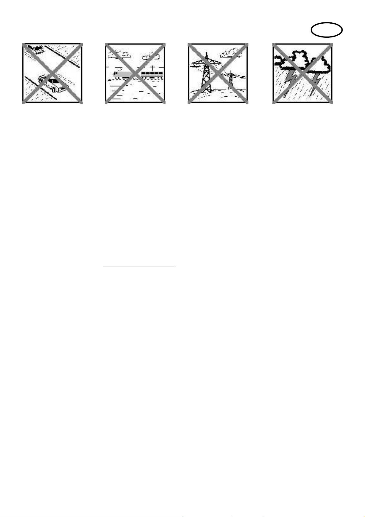
l Never # y in any location where you may endanger yourself of others, e.g. close to residential areas, overhead
cables, open roads and railway lines.
l Never # y towards people or animals. You may think that # ying low over other people’s heads is proof of your
piloting skill, but all it does is place others at unnecessary risk. It is in all our interests that you let other pilots
know that this is what you think. Always # y in such a way that you do not endanger yourself or others. Bear in
mind that even the best RC system in the world is subject to outside interference. No matter how many years of
accident-free # ying you have under your belt, you have no idea what will happen in the next minute.
GB
Page 3
Seite 10
Residual risks
Even if the model is operated in the correct manner, and you observe all safety aspects, there is always a certain residual
risk.
For this reason it is mandatory to take out third-party liability insurance. If you join a club or ! ying association, insurance
is usually available or included in the annual fee. Make sure that your insurance cover is adequate (i.e. that it covers
powered model aircraft). Always keep your models and your radio control equipment in perfect order.
The following hazards may occur owing to the model’s construction and type:
l Injury caused by the propeller: you must keep well clear of the area around the propeller from the moment that
the battery is connected. Please bear in mind that objects in front of the propeller may be sucked into it, and
objects behind the propeller may be blown away by it. The model may start moving when the propeller starts
to turn. You must therefore position the model in such a way that it cannot move towards other persons if the
motor should unexpectedly start running. When you are carrying out adjustment work involving the running
motor, you must ensure that the model is always held securely by an assistant.
l Crash caused by pilot error: this can happen even to the best of pilots, so it is essential to ! y exclusively in a
safe environment: an approved model ! ying site and suitable insurance are basic essentials.
l Crash caused by technical failure or unnoticed damage in transit or in the workshop. A thorough check of the
model before every ! ight is essential. However, you should also take into account at all times that material
failures can and do occur. Never ! y in a location where your model may damage or injure others.
l Keep within the stated operating limits. Excessively violent ! ying will weaken the airframe, and may result in
sudden material failure, or may cause the model to crash during a subsequent ! ight due to “creeping” consequent damage.
l Fire hazard caused by electronic failure or malfunction. Store batteries safely, and always observe safety
notes which apply to the airborne electronic components, the battery and the battery charger. Protect all electronic equipment from damp. Ensure that the speed controller and battery are adequately cooled.
The instructions which accompany our products must not be reproduced and / or published, in full or in part, in
print or any electronic medium, without the express written approval of Multiplex Modellsport GmbH & Co. KG.
GB
Page 4

Seite 11
Examine your kit carefully!
MULTIPLEX model kits are subject to constant quality checks throughout the production process, and we sincerely
hope that you are completely satis! ed with the contents of your kit. However, we would ask you to check all the parts
before you start construction, as we cannot exchange components which you have already worked on. If you ! nd
any part is not acceptable for any reason, we will readily correct or exchange it. Just send the component to our Model
Department. Please be sure to include the purchase receipt and a brief description of the fault.
We are constantly working on improving our models, and for this reason we must reserve the right to change the kit
contents in terms of shape or dimensions of parts, technology, materials and ! ttings, without prior noti! cation. Please
understand that we cannot entertain claims against us if the kit contents do not agree in every respect with the instructions and the illustrations.
Caution!
Radio-controlled models, and especially model aircraft, are by no means playthings. Building and operating them
safely requires a certain level of technical competence and manual skill, together with discipline and a responsible attitude at the fl ying fi eld. Errors and carelessness in building and fl ying the model can result in serious
personal injury and damage to property. Since we, as manufacturers, have no control over the construction,
maintenance and operation of our products, we are obliged to take this opportunity to point out these hazards
and to emphasise your personal responsibility.
Warning:
Like every aeroplane, this model has static limits. Steep dives and senseless manoeuvres inappropriate to the type
may result in the loss of the aircraft. Please note: we will not replace the model in such cases. It is your responsibility to
approach the airframe’s limits gradually. It is designed for the power system recommended in these instructions, but is
only capable of withstanding the " ight loads if built exactly as described and if it is in an undamaged state.
Recommended equipment:
Zacki ELAPOR 20g VE1 Item number: 852727
Li-BATT FX 3/1-450 (M6) Item number: 157311
Receiver RX-5 light M-LINK 2,4 GHz Item number: 55808
COCKPIT SX M-LINK classic, transmitter 2,4 GHz Item number: 45130/1/2
Combo MULTIcharger LN-3008 EQU w.Mains PSU, AC/DC 230V/12V 5,0A Item number: 92545
Charge lead w. high current plug (M6) Item number: 92516
Optional equipment:
Model-Service-Box Item number: 85500
GB
Page 5

Seite 12
Important note
This model is not made of Styrofoam™, and it is not possible to glue the material using white glue, polyurethane or
epoxy; these adhesives only produce super! cial joints, and simply break away under stress. Please be sure to use
medium-viscosity cyano-acrylate glue exclusively, preferably Zacki ELAPOR® # 59 2727, which is optimised specifi cally
for ELAPOR® particle foam. If you se Zacki ELAPOR® there is usually no need for cyano ‘kicker’ or activator. However,
if you wish to use a different adhesive which requires the use of activator, please note that these materials are injurious
to health, and should always be applied in the open air. Take care when handling all cyano-acrylate adhesives, as they
harden in seconds, so don’t get them on your fi ngers or other parts of the body. We strongly recommend the use of
goggles to protect your eyes. Keep the adhesive out of the reach of children! For certain joints it is also possible to use
hot-melt adhesive; the instructions indicate where this is the case.
Working with Zacki ELAPOR®
Zacki ELAPOR® has been developed specifi cally for glued joints in our models which consist of moulded ELAPOR®
foam parts.
Please observe the following points in order to obtain perfect joints:
• Avoid the use of activator. ‘Kicker’ signifi cantly weakens the joint. We advise leaving joined parts for 24 hours to obtain
maximum strength, particularly when the glued area is large.
• Activator should only be used for temporary, small-area joints (‘tacking’). Spray a little activator on one surface, and
allow it to air-dry for about thirty seconds.
• To obtain maximum joint strength you should lightly sand the surface with 320-grit abrasive paper before applying glue.
Bent parts - actually don’t exist. If you fi nd that a component has taken up a curve, perhaps after being transported, it is easy to straighten again. In this respect ELAPOR® behaves in a similar way to metal: bend the
component back slightly beyond the correct position, and the material will then spring back to its proper shape
when released, and maintain it. There are limits, however - don’t overdo it!
Bent parts - really do exist. If you wish to paint your model, apply MPX Primer # 60 2700 to the surfaces, wiping it on
very lightly as if you were cleaning the model. Paint must always be applied thinly and evenly, otherwise the component
will warp. Then you really will have bent parts, and they will also be heavy and perhaps even unusable. We have found
that matt-fi nish paints produce the best visual effect.
Technical information STUNTMASTER:
Wingspan: 870 mm
Overall length: 928 mm
All-up weight: 350 g
Total surface area: 24 dm²
Wing loading: 14,6 g/dm²
Channels: 4
RC Functions: rudder, elevator, aileron, motor
Flight time: ca. 5 min (3S ~450 mAh)
Note: please remove the pictures from the center of the instructions!
Page 6

Seite 13
Congratulations on your new STUNTMASTER!
Completing the model:
You will need the following tools to complete the model:
• Ruler or tape measure
• Small cross-point screwdriver
• Slot-head screwdriver (approx. 5 mm)
• Sharp balsa knife
• Pointed-nose pliers
• Zacki Elapor adhesive # 852727
Start by checking the kit components against the Parts List
on page 15 (Fig. 01), to ensure that everything is present
in the box.
1. Installing the undercarriage (Fig. 02):
Apply a drop of Zacki to each side of the fuselage 1,
and push the two undercarriage legs 10 and 11 into the
appropriate openings. Ensure that the fuselage is level
when standing on the undercarriage.
2. Attaching the wing (Fig. 03):
Working from the right-hand side, slide the wing 2 half-way
through the fuselage 1. Now apply a little Zacki to the central
area of the wing, top and bottom.
àTip: if you apply the glue only to the left-hand area of the
wing centre section, the action of pushing the wing into place
will distribute the adhesive over the whole joint surface.
Push the wing fully into the fuselage, checking immediately
that the two components are exactly at right-angles to each
other. It is essential that the wing is “square” to the fuselage,
i.e. dimensions A and B must be identical. The wing must
also be at right-angles to the fuselage when viewed from
the nose or tail. If excess glue is squeezed out of the joint,
wipe it off using a paper towel.
3. Attaching the tailplane (Fig. 4):
The procedure for " tting the tailplane 3 is similar to that for
attaching the wing. Dimensions C and D must be identical.
Once again, ensure that everything is “square”.
4. Attaching the rudder (Figs. 5 & 6):
First glue the in-" ll piece 9 in the opening in the tail end
of the fuselage 1. The hinges for the rudder 4 can now be
glued in the prepared slots.
àTip: to ensure that the adhesive actually enters the hinge
slots without spilling out, compress the tip of the Zacki bottle
slightly using pointed-nose or # at-nose pliers, so that the
exit opening is oval.
Take care to allow no more than a little adhesive to be
squeezed out of the hinge slots, and maintain a gap about 1
mm wide between rudder and " n (rear edge of the fuselage).
It is important that the rudder swivels freely and easily from
one extreme to the other.
5. Installing the servos (Figs. 07 - 09):
First remove the battery hatch 7 from the fuselage 1.
Apply a little Zacki to the base of the horn 24 and glue it
in the moulded-in recess in the left-hand aileron. Remove
the aileron servo from its well, and set it to centre (neutral)
from the transmitter. Fit the output lever on the servo output
shaft, and tighten the retaining screw " rmly. The servo can
now be glued in the appropriate opening in the fuselage by
applying a little Zacki at each mounting lug.
Repeat the procedure with the rudder and elevator servos.
Route all the servo leads through to the front fuselage
compartment.
6. Installing the wing and tailplane braces (Figs. 10 - 12):
Glue the supports 5 and 6 to the underside of the wing at the
marked points, then glue the braces 16 (front, approx. 1.3
x 300 mm) and 17 (rear, approx. 1.3 x 305 mm) in place as
shown. It is important that the braces are not under tension
when " tted, as this could introduce warps into the wing.
Check that the wing is still at right-angles to the fuselage
when viewed from the nose and tail. Fix the braces to the
wing and fuselage, applying a small drop of Zacki to the
transitions between the plastic and CFRP parts.
Use the same general procedure to install the tailplane
braces 15 (approx. 1.5 x 130 mm).
7. Installing the control surface linkages (Figs. 13 - 22):
AILERONS:
Locate the clevises attached to the pushrods 18 (approx.
1.3 x 130), connect them to the outer holes in the aileron
servo output lever, then slide the rubber sleeves over them
to prevent them coming adrift accidentally. Connect the
pushrod clevises to the outer holes in the aileron horns, and
secure them in the same way with small pieces of rubber
sleeve. Switch the radio control system on, and set the
aileron servo to neutral. Now slide the clevises in or out to
adjust the length of the pushrods, so that both ailerons are
also at the neutral (centre) position; tighten the clamping
screws " rmly when you are satis" ed. Check that the aileron
linkage works correctly, and that travels of around 95 mm
up and 75 mm down are available, as required for 3D # ying.
If necessary, cut away a little foam from the fuselage to
prevent the pushrods fouling it at the extremes of travel.
ELEVATOR:
Thread the elevator pushrod 19 (approx. 1.3 x 510 mm)
through the black plastic guides on the left-hand side of the
fuselage, and connect the pushrod to the outer hole of the
elevator horn. Connect the pushrod to the servo output arm
using a hole 15 mm from the servo’s central axis. Secure
the pushrod and the clevises using the method described
for the ailerons.
Page 7

Seite 14
RUDDER:
Here there are two options: either a pushrod or pull-cables.
Advantages of the pushrod linkage:
• Easier to install
• Less sensitive to temperature ! uctuations
• Easier to adjust
Advantages of the pull-cable linkage:
• More ef" cient transfer of servo power
• Lighter
• Reduced lost motion (slop)
In the " nal analysis both methods work well, and the choice
is really just a matter of personal taste. All the parts for both
versions are included in the kit, so either can be installed.
RUDDER option: pushrod linkage (Fig. 16):
Repeat the general procedure described for the elevator and
aileron linkages: connect the rudder pushrod 20 (approx.
1.3 x 620 mm) to the outer hole of the rudder horn, and
the second hole from the outside of the servo output arm.
Secure the clevises as already described, and tighten the
clamping screws " rmly.
RUDDER option: pull-cable option (Figs. 17 - 22):
Use a clean, sharp balsa knife to cut off the plastic supports
and raised foam sections on the right-hand side of the
fuselage, leaving them ! ush with the foam surface. Thread
the pull-cable 21 through the outer hole in the rudder horn,
and tie a knot at a point about 8 mm forward of the horn.
Apply a drop of Zacki to the knot to prevent it working loose.
Route the cable forward as far as the servo output lever,
and cut it off leaving an excess of about 10 cm. Referring
to Fig. 21, thread it through the outer hole (or second hole
from the outside) of the servo output lever. Set the servo
to centre from the transmitter, and tape the rudder in the
centre position.
Fit the screw 22 (1.4 x 6 mm) and the washer 23 (5 mm Ø)
in the third hole from the outside of the output lever, tighten
it about half-way, then tie the cable round it. Fix the cable
to the screw with a little Zacki. If you now carefully tighten
the screw further, the cable will be placed under tension.
Repeat the procedure with the other side, and adjust the
pull-cable linkage so that the rudder is exactly central when
the servo output lever is at neutral.
8. Installing the motor and propeller (Figs. 23 - 26):
Slip the speed controller through the motor bulkhead, and
permanently " x the motor in place using the retaining screws
25 (2 x 5 mm). Attach the propeller 14 to the motor using
the propeller adapter ring 15. Glue the locating pin 12 in
the propeller with a little Zacki, then add the spinner, again
using a little Zacki or contact cement.
9. Installing the receiver and fl ight battery
(Figs. 27 & 28):
Connect all the servos to the receiver in the sequence stated
in your RC system instructions, then push the receiver into
the nose compartment as shown in Fig. 27. Install the ! ight
pack in the forward position.
10. Balancing (Figs. 29 & 30):
Push the battery hatch into place, and balance the model
on your " ngertips: the correct Centre of Gravity position
is 95 - 105 mm, measured from the wing leading edge at
the root.
11. Recommended control surface travels
for the classic aerobatic schedule:
Rudder: 80 mm right / left, 50% EXPO
Elevator: 40 mm up, 40 mm down, 40%
EXPO
Ailerons: 35 mm up, 35 mm down, 40%
EXPO
Mixer (linear): 2% aileron to rudder, opposite travel
ài.e.: ailerons de! ect left by 2%
at full right-rudder
For 3D aerobatics:
Rudder: 110 mm right / left, 60% EXPO
Elevator: As much as possible up / down,
60% EXPO
Ailerons: 95 mm up / 75 mm down, 60%
EXPO
Mixer (linear): 5% aileron to rudder opposite travel
ài.e.: ailerons de! ect left by 5%
at full right-rudder
Page 8

Seite 15
Parts List - STUNTMASTER# 264293:
Part No. Qty Description Material Dimensions
1 1 Fuselage Elapor Ready made
2 1 Wing Elapor Ready made
3 1 Tailplane Elapor Ready made
4 1 Rudder Elapor Ready made
5,6 2 Brace support Elapor Ready made
7 1 Battery hatch Elapor Ready made
8 3 Spinner Elapor 40 mm Ø
9 1 Fin in-! ll piece Elapor Ready made
10 1 Left-hand undercarriage leg Elapor Ready made
11 1 Right-hand undercarriage leg Elapor Ready made
12 2 Spinner centring pin CFRP 2.5 x 13
13 2 O-ring for attaching propeller Rubber 17 mm Ø
14 1 Propeller, GWS EP Plastic 9 x 5“
15 2 Propeller adapter ring Aluminium 10 mm Ø
15 2 Tailplane brace CFRP / plastic approx. 1.5 x 130 mm
16 2 Front wing brace CFRP / plastic approx. 1.3 x 300 mm
17 2 Rear wing brace CFRP / plastic approx. 1.3 x 305 mm
18 2 Aileron pushrod CFRP / plastic approx. 1.3 x 130 mm
19 1 Elevator pushrod CFRP / plastic approx. 1.3 x 510 mm
20 1 Rudder pushrod CFRP / plastic approx. 1 3 x 620 mm
21 1 Rudder pull-cable Kevlar approx. 3.3 m long
22 4 Screw Metal 1.4 x 6 mm
23 4 Washer Metal 5 mm Ø
24 1 L.H. aileron horn Plastic Ready made
24 3 Pushrod clevis Plastic Ready made
25 4 Motor mounting screw Metal 2 x 5 mm
26 1 STUNTMASTER building instructions Paper Din A 4
27 1 Model complaint processing form Paper Din A 5
Page 9

Seite 21
pic. 02
pic. 01
pic. 03
Page 10

Seite 22
pic. 04
pic. 06pic. 05
pic. 07
Page 11

Seite 23
pic. 04
pic. 09
pic. 08
pic. 10
Page 12

Seite 24
pic. 12
pic. 11
pic. 13
Page 13

Seite 25
pic. 15pic. 14
pic. 16
pic. 17
Page 14

Seite 26
pic. 18
pic. 19
pic. 21
pic. 20
Page 15

Seite 27
pic. 22 pic. 23
pic. 24 pic. 25
pic. 26
Page 16

Seite 28
pic. 27
pic. 28
pic. 29
pic. 30
Page 17

Seite 41
Aviso importante:
¡Este modelo no es de Styropor ™! Por tanto, no debe usar cola blanca, poliuretano o Epoxy para las uniones.
Estos pegamentos solo producen una unión superfi cial y que se despega fácilmente. Utilice exclusivamente pegamentos
con base de cianocrilato de viscosidad media, preferentemente Zacki -ELAPOR® # 59 2727, que está optimizado para
las partículas de ELAPOR® y un pegamento instantáneo compatible. Al utilizar Zacki-ELAPOR® podría ahorrarse el
uso de activador. Sin embargo, si quiere utilizar otro pegamento y no desea prescindir del activador, deberá aplicarlos
sobre el modelo en exteriores, por razones de seguridad. Cuidado al trabajar con pegamentos a base de cianocrilato.
Estos pegamentos fraguan en cuestión de segundos, y por este motivo no deben entrar en contacto con los dedos u
otras partes del cuerpo. ¡No olvide usar gafas para proteger sus ojos!
¡Mantener lejos de los niños! En algunos puntos también puede usarse cola termo-fusible. ¡Se lo advertiremos adecuadamente en las instrucciones!
Trabajar con Zacki ELAPOR®
Zacki ELAPOR® ha sido desarrollado específi camente para el pegado de nuestros modelos de espuma fabricados con
ELAPOR®
Para que el pegado sea óptimo, debe respetar los siguientes puntos:
• Evite la utilización de activador. Con él, la unión se debilita notablemente.
Ante todo, al pegar grandes superfi cies le recomendamos dejar secar las piezas durante 24 horas.
• El activador tan solo debería usarse para fi jaciones puntuales. Aplique un poco de activador en uno de los lados.
Deje que se ventile el activador durante unos 30 segundos aproximadamente.
• Para un pegado óptimo, lije suavemente la superfi cie con un papel de lija (grano tipo 320).
¿Se dobló? – ¡No pasa nada!. En caso de que algo se haya doblado, por ejemplo durante el transporte, se puede
volver a enderezar. El ELAPOR® se comporta como si fuse metal. Si lo dobla un poco en el sentido contrario,
el material vuelve a su estado normal, manteniendo la forma. Por supuesto, todo tiene un límite - ¡No lo fuerce
demasiado”
¿Se dobló? – ¡Ya está!. Si quiere pintar su modelo, aplique una ligera capa de imprimación MPX Primer # 602700, como
si limpiase su modelo. Bajo ningún concepto debe aplicar gruesas capas o de manera irregular, podría estropear su
modelo. ¡Se torcerá, se volverá pesado y a menudo hasta frágil! Con una pintura mate conseguirá los mejores resultados.
Características técnicas STUNTMASTER:
Envergadura: 870 mm
Longitud total: 928 mm
Peso: 350 g
Superfi cie alar: 24 dm²
Carga alar: 14,6 g/dm²
Canales de mando RC: 4
Funciones RC: Profundidad, dirección, alerones, motor
autonomía de vuelo: ca. 5 min (3S 450 mAh)
Aviso: ¡Separe las ilustraciones del cuadernillo central!
Page 18

Seite 42
Le damos la enhorabuena por su nuevo Multiplex
STUNTMASTER.
Montaje del conjunto:
Para montar el modelo necesitará las siguientes
herramientas:
• Metro plegable
• Destornillador de estrella, pequeño
• Destornillador plano (aprox. 5mm.)
• Cuchilla a! lada
• Alicantes de punta
• Zacki Elapor # 852727
Compruebe que las piezas enviadas son de su satisfacción
con la lista de piezas de la página 44. (Img.01)
1. Fijación del tren de aterrizaje (Img.02):
Aplique una gota de Zacki en el lado derecho e izquierdo
del fuselaje 1 e inserte ambas patas del tren de aterrizaje
10 y 11 en la abertura prevista para ello. Compruebe que
el fuselaje quede recto respecto al tren de aterrizaje.
2. Fijación de las alas (Img.03):
Desde el lado derecho, pase el ala 2, hasta su mitad, a
través del fuselaje 1. Aplique un poco de Zacki en la parte
superior e inferior de la zona central del ala.
àNota: Si aplica el pegamento solo en la parte izquierda
del puente central del ala, el pegamento se irá aplicando
sobre la super! cie total de pegado a medida que vaya
insertando el ala.
Termine de insertar totalmente el ala en el fuselaje.
Compruebe que el ala queda pegada al fuselaje formando
un ángulo recto, las longitudes A y B deben ser idénticas.
El ala tiene que formar en todo momento un ángulo recto
respecto al fuselaje. Elimine, si fuese necesario, cualquier
sobrante de pegamento con un pañuelo de papel.
3. Fijación del estabilizador horizontal (Img. 4):
Para montar el estabilizador horizontal 3 proceda de manera
análoga a como montó el ala. Las dimensiones C y D deben
ser idénticas. Compruebe también aquí la alineación en
ángulo recto.
4. Montaje del timón de dirección (Img. 5 & 6):
Comience pegando la pieza 9 al fuselaje 1. Ahora, pegue las
bisagras del timón de dirección 4en las ranuras preparadas
para ello.
àNota: Para aplicar el pegamento en las ranuras sin que se
derrame, apriete la parte delantera de la boquilla del Zacki
utilizando unos alicates de punta o planos, de manera que
la apertura de la boquilla se vuelva ovalada.
Además, deberá preocuparse de que rebose muy poco
pegamento y de dejar un margen de 1mm., aprox., entre
el timón y el canto trasero del fuselaje. Debe moverse
libremente y con facilidad.
5. Instalación de los servos (Img. 07-09):
Comience retirando la tapa de la batería 7 del fuselaje 1.
Usando algo de Zacki, pegue el horn de timón 24 en la
posición prevista en el lado izquierdo. Coloque el servo
de alerones en su encastre y, usando su equipo de radio,
póngalo en posición neutra. Atornille el brazo del servo,
apriete bien el tornillo. Pegue el servo, usando un poco de
Zacki en las lengüetas, en la abertura prevista del fuselaje.
Proceda de manera análoga con el servo del timón de
dirección y el de profundidad.
Lleve todos los cables de servos a la parte delantera del
fuselaje.
6. Arriostrado del ala y del estabilizador horizontal
(Img. 10-12):
Pegue los apoyos de las riostras 5 & 6 en las posiciones
indicadas de la parte inferior del ala. Ahora, pegue las
riostras 16 (delante, aprox. 1,3x 300 mm.) y 17 (detrás,
aprox. 1,3x 305 mm.). Asegúrese de que las riostras se
pegan sin estar en tensión para evitar que las alas se
tuerzan y que se sigan manteniendo en ángulo recto
respecto al fuselaje. Fije las riostras también a los puentes
que van desde el plástico a las piezas de carbono usando
unas gotas de Zacki.
Para montar las riostras del estabilizador horizontal 15
(aprox. 1,5x130 mm.) proceda de manera análoga a como
montó el ala.
7. Instalación de las varillas de los timones (Img. 13-22):
Alerones:
Enganche los retenes de las varillas de trasmisión 18
(aprox. 1,3x 130) en el agujero más externo del horn
del servo de alerones. Asegúrelos colocando un tubito
de goma para evitar que se desenganchen sin querer.
Enganche los retenes de varilla en el agujero superior de
la palanca de alerones y fíjelos también usando un trocito
de tubo de goma. Encienda su equipo de radio y ponga
el servo de alerones en posición neutra. Ahora, use un
destornillador para ajustar con los tornillos la longitud de
los retenes de varilla, de modo que ambos alerones queden
en posición neutra. Apriete bien los tornillos. Compruebe
el funcionamiento de la transmisión de los alerones y que
pueden desarrollar un recorrido para 3D de unos 95 mm.
Arriba / 75 mm. Abajo. En caso necesario, retire un poco
de espuma del fuselaje de manera que la varilla pueda
moverse libremente.
Profundidad:
Pase la varilla de transmisión del timón de profundidad 19
(Aprox. 1,3x 510 mm.) por los soportes de plástico negro en
la parte izquierda del fuselaje. Enganche la varilla al timón
de profundidad usando el agujero más externo. Conéctela
al brazo del servo de manera que la distancia al eje central
del servo sea de 15 mm. Fije la varilla y las transmisiones
de manera análoga a como ! jó los alerones.
Page 19

Seite 43
Dirección:
Aquí hay dos posibilidades, o transmisión por varilla o por
cable.
Ventajas de la transmisión por varilla:
• Más fácil de montar
• Independiente de la temperatura
• Más fácil de ajustar
Ventajas de la transmisión por cable:
• Transmisión óptima de potencia
• Más ligera
• Sin holguras
A ! n de cuentas ambas son posibles y será una cuestión
de gusto personal por cual de ellas se decidirá, estando
incluidas todas las piezas necesarias para ello en el kit.
Dirección con opción de varilla (Img. 16)
Proceda de manera análoga como lo hizo con los
alerones o el timón de profundidad. Enganche la varilla de
transmisión del timón de dirección 20 (aprox. 1,3 x 620 mm.)
en el agujero exterior del horn del timón y en el segundo
agujero desde afuera en el brazo del servo. Fije la varilla
de transmisión como se describió anteriormente y apriete
los tornillos.
Timón de dirección con opción de cable (Img. 17-22):
Use una cuchilla a! lada y limpia para costar los soportes
de plástico de la mitad derecha del fuselaje que están
pegados a la espuma. Enhebre el cable de transmisión
21 en el agujero externo del horn del timón de dirección y
anúdelo de modo que el nudo quede a unos 8 mm. del horn
de dirección. Asegure el nudo con unas gotas de Zacki.
Tire del cable hasta llegar al brazo del servo y córtelo
dejando unos 10 cm. de sobrante. Páselo, como se muestra
en la imagen 21, por el agujero exterior o el segundo
más externo del brazo del servo. Use su equipo de radio
para colocar el servo en posición neutra y ! je el timón
de dirección en posición neutra con unas tiras de cinta
adhesiva.
Apriete el tornillo 22 (1,4x6 mm.) y la arandela 23 (Ø5 mm.)
más o menos hasta la mitad en el tercer agujero, desde
afuera, y anude el cable alrededor. Fije el cable al tornillo
usando algo de Zacki. Cuando el tornillo vuelva a apretarse,
el cable se irá tensando. Proceda en el otro lado de manera
análoga y ajuste la transmisión de manera que el brazo del
servo y el timón queden en posición neutral.
8. Montaje del motor y de la hélice (Img. 23-26):
Pase el regulador a través de la cuaderna parallamas y
atornille el motor con los tornillos 25 (2x5 mm.). Fije al motor
la hélice 14 con el anillo adaptador 15. Pegue el perno de
centrado 12 con un poco de Zacki a la hélice y use un poco
de Zacki o pegamento de contacto para pegar el cono.
9. Instalación del receptor y las baterías (Img. 27 & 28):
Conecte todos los canales de los servos al receptor según
la asignación de su emisora y póngalos como se indica en
la imagen 27. Ponga la batería en la posición delantera.
10. Equilibrado (Img. 29 & 30):
Coloque la tapa de la batería y equilibre el modelo de modo
que el centro de gravedad quede en la zona de 95 - 105
mm. medidos desde el borde de ataque del ala.
11. Recorridos recomendados de los timones
Para el programa de acrobacia clásica:
Timón de dirección: derecha/izquierda 80 mm.
50% EXPO
Timón de profundidad: Arriba 40 mm, abajo 40
mm. 40% EXPO
Alerones: Arriba 35 mm, abajo 35 mm. 40%
EXPO
Mezclador (lineal): 2% de alerones para compensar
dirección
àEs decir: Con toda la dirección a la derecha, el
alerón manda un 2% a la izquierda.
Para acrobacia 3D:
Timón de dirección: derecha/izquierda: 110
mm., 60% EXPO
Timón de profundidad: arriba / abajo: Todo lo que
de 60% EXPO
Alerones: Arriba 95 mm., abajo 75 mm. 60%
EXPO
Mezclador (lineal): 5% de alerones para compensar
dirección
àEs decir: Con toda la dirección a la derecha, el
alerón manda un 5% a la izquierda.
Page 20

Seite 44
Lista de partes STUNTMASTER STUNTMASTER# 264290 / # 264291:
Ordinal Pieza Descripción Material Dimensiones
1 1 Fuselaje Elapor Pieza prefabricada
2 1 Alas Elapor Pieza prefabricada
3 1 Estabilizador horizontal Elapor Pieza prefabricada
4 1 Estabilizador vertical Elapor Pieza prefabricada
5,6 2 Apoyos de las riostras Elapor Pieza prefabricada
7 1 Tapa de la batería Elapor Pieza prefabricada
8 3 Cono Elapor Ø 40mm.
9 1 Pieza de relleno del timón de dirección, Elapor Pieza prefabricada
10 1 Pata izquierda del tren de aterrizaje Elapor Pieza prefabricada
11 1 Pata derecha del tren de aterrizaje Elapor Pieza prefabricada
12 2 Perno de centrado del cono Fibra de carbono 2,5x13
13 2 Junta tórica para montar la hélice Goma Ø 17mm.
14 1 Hélice GWS EP Plástico 9x5”
15 2 Anillo adaptador de hélice Aluminio Ø 10mm.
15 2 Riostras del estabilizador horizontal Fibra de carbono, Aprox. 1,5x130mm.
16 2 Riostras delanteras del ala Fibra de carbono, Aprox. 1 x 300mm.
17 2 Riostras traseras del ala Fibra de carbono, Aprox. 1 x 305mm.
18 2 Varilla de transmisión de alerones Fibra de carbono, Aprox. 1,3 x 130mm.
19 1 Varilla de transmisión del timón de profun., Fibra de carb., Aprox. 1,3 x 510mm.
20 1 Varilla de transmisión del timón de dirección, Fibra de carb., Aprox.1,3x620mm.
21 1 Cable para transmisión del timón de dirección, Kevlar, Aprox. 3,3 m. de largo
22 4 Tornillos Metal 1,4 x 6 mm.
23 4 Arandelas Metal Ø5 mm.
24 1 Horn de alerón izquierdo Plástico Pieza prefabricada
24 3 Retén de varilla Plástico Pieza prefabricada
25 4 Tornillos para ! jar el motor Metal 2 x 5 mm.
26 1 Instrucciones de montaje STUNTMASTER Papel Din A4
27 1 Hoja de reclamaciones para modelos Papel Din A5
Page 21

Seite 45
# 22 4376
Rumpf (Ohne RC, Akkudeckel)
Fuselage (without electrics,
battery cap)
# 22 4377
Akkudeckel /
Battery cap
# 22 4380
Höhenleitwerk
Elevator
# 22 4381
Hauptfahrwerk /
Main landing gear
# 22 4378
Seitenleitwerk / Rudder
# 22 4379
Trag! ächen / Wings
Ersatzteile / Spareparts
# 22 4381 # 22 4378
# 22 4377 # 22 4380
Page 22

Seite 46
# 73 2505
Propeller GWS EP-9x5“
# 22 4382
Spinner
# 22 4386
O-Ringe für Propellermontage
(5 Stk.) / O-rings
# 22 4385
Kleinteilesatz / Small part set
# 22 4383
Anlenkungssatz / Linkage set
# 22 4384
Abtrebungssatz / Bracing set
# 73 2505 # 22 4382
# 22 4386 # 22 4385
Page 23

Seite 47
# 33 3119
Motor
PERMAX BL-O 2206-1050
# 7 2266
Regler / ESC
MULTIcont BL-18 SD
# 6 5113
Servo MS-12016
Page 24

Seite 48
MULTIPLEX Modellsport GmBH & Co. KG. Westliche Gewerbestrasse 1 D-75015 Bretten-Gölshausen
www.multiplex-rc.de
 Loading...