

Page 1
AC DUAL
BALANCE CHARGER
INSTRUCTION MANUAL
WARNING: THE CHARGING OF RC HOBBY BATTERIES CAN BE DANGEROUS. FAILURE TO FOLLOW THE
INSTRUCTIONS AND WARNINGS IN THIS MANUAL MAY RESULT IN PROPERTY DAMAGE AND/OR LOSS OF LIFE.
Page 2

Table of Contents
Table of Contents:
Introduction...................................................................................................................................03
Warning and Safety Notes......................................................................................................04
Product Layout.............................................................................................................................07
Input Functions.............................................................................................................................08
Spec cations | Features...........................................................................................................09
Charger Connections................................................................................................................11
Program Flow Chart...................................................................................................................12
Charger Operations...................................................................................................................13
Memory Set and Call - Out......................................................................................................16
Battery Resistance Meter.........................................................................................................18
Warning and Error Messages.................................................................................................19
System Setting.............................................................................................................................20
Commonly Used Terms............................................................................................................22
Conformity Declarations........................................................................................................24
Disposal and Prop 65 Warning............................................................................................25
Warranty and Service...............................................................................................................27
2
Page 3
Introduction
Congratulations on your choice of the RDX2 Mini charger from Hitec RCD. The RDX2 Mini is a highperformance, microprocessor-controlled charger with battery management capabilities that are suitable
for use with most popular battery types. The RDX2 Mini also features integrated balancing for two-four
cell, Lithium-Polymer (LiPo), Lithium-Ferrite (LiFe) and Lithium-Ion (Li-Ion), as well as the latest high
voltage Lithium-Polymer (LiHV) batteries. Although simple to operate, the RDX2 Mini does require some
background knowledge for successful and safe operation.
Please read this entire operating manual before using the RDX2 Mini Charger. If you are unsure
of its proper operation after reading the manual, please seek advice from an experienced
hobbyist or someone familiar with proper battery charging procedures.
THE CHARGING AND DISCHARGING OF RC HOBBY BATTERIES CAN BE DANGEROUS. FAILURE TO FOLLOW THESE
EXPLICIT WARNINGS CAN RESULT IN PROPERTY DAMAGE AND/OR LOSS OF LIFE.
Warning
A NEVER LEAVE YOUR CHARGER UNATTENDED WHILE IN OPERATION.
A NEVER CHARGE ON OR AROUND COMBUSTIBLE MATERIALS.
A NEVER CHARGE A DAMAGED BATTERY PACK.
A LOW COST, NO-NAME BATTERY PACKS POSE THE MOST DANGER. WE RECOMMEND YOU ONLY USE BATTERY
PACKS THAT ARE SOLD AND WARRANTIED BY A REPUTABLE COMPANY.
A IT IS HIGHLY RECOMMENDED THAT YOU UTILIZE A SAFETY DEVICE SUCH AS A STEEL CASE OR LIPO SACK™
WHILE CHARGING LITHIUM CHEMISTRY BATTERIES.
A IT IS HIGHLY RECOMMENDED THAT YOU KEEP AN OPERABLE “CLASS A” FIRE EXTINGUISHER IN THE
CHARGING AREA.
FAILURE TO FOLLOW THESE WARNINGS CAN BE CONSIDERED NEGLIGENCE BY THE OPERATOR AND MAY
NEGATE ANY CLAIMS FOR DAMAGES INCURRED.
Hitec RCD will not be held responsible for any damages or injuries that may occur by persons who fail to
follow these warnings or who fail to properly follow the instructions in this manual.
Warning: Be sure to read this section for your own safety.
Caution: Be sure to read this section to prevent accidents and damage to your charger.
Note
Tip
Tip: This section will help you maximize the performance of your charger.
Note: This section will provide more detailed explanations.
Caution
Warning
These warnings and safety notes are of the utmost importance. You must follow these instructions for maximum safety.
Failure to do so can damage the charger and the battery and in the worst cases, may cause a re.
3
Page 4

Warning and Safety Notes
NEVER LEAVE THE CHARGER UNATTENDED WHILE IT IS CONNECTED TO ITS POWER
SOURCE. IF ANY MALFUNCTION IS FOUND, TERMINATE THE PROCESS AT ONCE AND
REFER TO THE OPERATION MANUAL.
Warning
A The allowable AC input voltage is 100-240V AC.
A Keep the charger away from dust, damp, rain, heat, direct sunlight and excessive vibration.
A If the charger is dropped or su ers any type of impact, it should be inspected by an
authorized service station before using it again.
A This charger and the battery should be put on a heat-resistant, non- ammable and non-
conductive surface.
A Never place a charger on a car seat, carpet or similar surface. Keep all ammable, volatile
materials away from the operating area.
A Make sure you know the speci cations of the battery to be charged to ensure it meets the
requirements of this charger. If the program is set up incorrectly, the battery and charger
can be damaged.
A Fire or explosion can occur due to overcharging.
A To avoid a short circuit between the charge lead, always connect any charge adapters to the
charger rst, then connect the battery. Reverse the sequence when disconnecting.
A Never attempt to charge the following types of batteries:
• A battery tted with an integral charge circuit or a protection circuit
• A battery pack which consists of di erent types of cells (including di erent manufacturer’s
cells)
• A battery that is already fully charged or just slightly discharged and non-rechargeable
batteries (these pose an explosion hazard)
• A faulty or damaged battery
• Batteries installed in a device or which are electrically linked to other components
• Batteries that are not expressly stated by the manufacturer to be suitable for the currents
the charger delivers during the charge process
4
Page 5
Warning and Safety Notes Continued
PLEASE BEAR IN MIND THE FOLLOWING POINTS BEFORE YOU
COMMENCE CHARGING:
• Did you select the appropriate program suitable for the type of battery you are charging?
• Did you set up the adequate current for charging?
• Have you checked the battery voltage? Lithium battery packs can be wired in parallel and/or in
series, i.e. a 2-cell pack can be 3.7V (in parallel) or 7.4V (in series).
• Have you checked that all connections are rm and secure?
• Make sure there are no intermittent contacts at any point in the circuit.
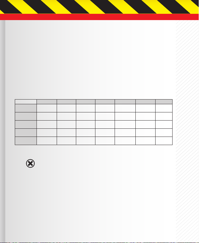
Standard Battery Parameters
Nominal
Voltage
Max. Charge
Voltage
Storage
Voltage
Allowable Fast
Charge
Min. Cell
Voltage
Warning
LiPo LiPo HV LiIon LiFe NiCd NiMH Pb
3.7V/cell 3.8V/cell 3.6V/cell 3.3V/cell 1.2V/cell 1.2V/cell 2.0V/cell
4.2V/cell 4.35V/cell 4.1V/cell 3.6V/cell 1.5V/cell 1.5V/cell 2.46V/cell
3.8V/cell 3.85V/cell 3.7V/cell 3.3V/cell n/a n/a n/a
≤ 1C ≤ 1C ≤ 1C ≤ 4C 1C-2C 1C-2C ≤ 0.4C
3.0-3.3V/cell 3.1-3.4V/cell 2.9-3.2V/cell 2.6-2.9V/cell 0.1-1.1V/cell 0.1-1.1V/cell 1.8V/cell
WHEN ADJUSTING YOUR RDX2 MINI CHARGING PARAMETERS, BE SURE YOU
SELECT THE PROPER BATTERY TYPE AND CELL VOLTAGE FOR THE TYPE OF CELL YOU
ARE CHARGING. CHARGING BATTERIES WITH THE WRONG SETTINGS MAY CAUSE
THE CELLS TO BURST, CATCH FIRE OR EXPLODE.
5
Page 6

Warning and Safety Notes Continued
Charging
Before charging your batteries, it is critical that you determine the maximum allowable charge rate for
your batteries. The RDX2 Mini is capable of charging at high rates that may not be suitable or safe for your
particular batteries. For example, Lithium cells are typically safe to charge at 1C, or the total mAh÷1000.
A 1200mAh battery would have a 1C charge rate of 1.2 amps. A 4200mAh battery would have a 1C charge
rate of 4.2 amps. Some manufacturers are o ering Lithium cells that can be charged at greater than 1C but
this should ALWAYS be veri ed before charging a Lithium battery at rates higher than 1C.
Voltage is just as critical as the charging amperage rate and this is determined by the number of cells
in series, or “S”. For example, a 3S LiPo is rated at 11.1 volts (“S” multiplied by a single LiPo cell with a
nominal voltage of 3.7 volts DC. 3 cells x 3.7 volts each equals 11.1 volts DC).
Connect the battery’s main leads to the charger output: red is positive and black is negative. Keep in
mind that the gauge or thickness of your charging leads from the RDX2 Mini to your battery must be of
an acceptable current rating to handle the applied charge current. For maximum safety and charging
e ectiveness, always match or exceed the main battery lead rating when assembling or selecting your
charging leads. If you charge a battery at a high current rate (amperage) with a charging lead not rated for
the chosen amperage, the wire could get hot, catch re, short out and/or potentially destroy your battery
and the charger.
When in doubt, always use a higher gauge wire (lower AWG number). It is common
to see charging leads constructed of 14AWG, 16AWG or 18AWG wire. Always refer to
recommendations from your battery manufacturer for your speci c battery type and size
before initiating a charge or discharge process.
Do not attempt to disassemble or modify Lithium or Lead-Acid battery packs.
6
BATT. Type | Stop Button
DEC. (Decrease) Button
Page 7
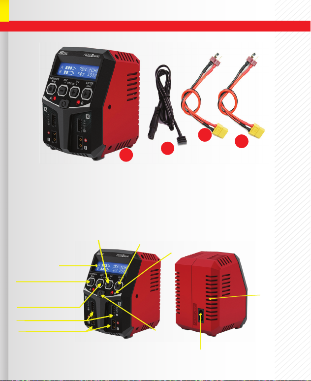
Product Layout
1. RDX 2 Mini Charger
2. AC Cord
LCD Display
BATT. Type | Stop Button
DEC. (Decrease) Button
Balance Lead Socket
Battery Connector XT60 Female
INC. (Increase) Button
1
3. T-Type Connector
4. T-Type Connector
Start / Enter Button
Channel A to B or
2
LED Indicator
Switch From
Vice Versa
3
AC Input (100-240V)
4
Ventilation
Fan
7
Page 8
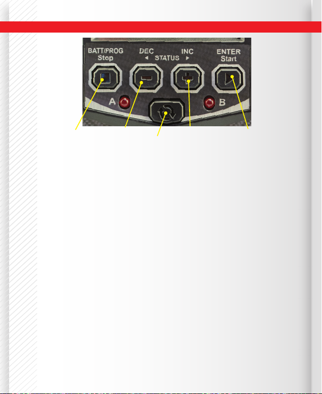
Input Functions
BATT. Type/Stop Button
Stop the progress of
the current action
or cycle back to the
previous step / screen.
DEC. Button
Scroll through
available menus
or decrease
parameter
values.
CHANNEL button
It is used to
switch from
Channel A to B
or vice versa.
INC. Button
Scroll through
available menus
or increase
parameter values.
Enter/Start Button
Used to enter parameter
or store parameter on
screen & start charging.
BATT PROG / STOP Button:
Stop a func tion in-progress or to go back to previous step/screen.
DEC Button:
Scroll through menus or decrease the parameter value.
INC Button:
Scroll through the menus or increase the parameter value.
ENTER/ START Button:
Used to enter parameter or store parameter on screen & start charging.
CHANNEL Button:
It is used to switch from Channel A to B or vice versa.
When changing a parameter value in the program, press the START/ENTER button to make it blink, then
change the value by pressing the DEC and INC button. The value will be stored by repressing the START/
ENTER button. If there is a second parameter to edit on the same screen, it will begin blinking after you
con rm the rst parameter value. When starting the charge process, press and hold the START/ENTER
button for 3 seconds. When stopping the charge process or go back to previous step/screen, press the
BATT PROG/STOP button once.
When you rst power the charger on, it displays the last parameters used. From here you can change
the battery type or press enter to change the charge parameters, charge current rate and/or battery cell
count. If you are charging a battery identical to the last one used, then simply press and HOLD the start
button for 3 seconds to begin that process.
8
Page 9
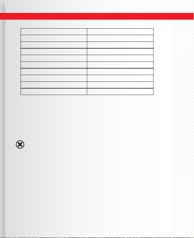
Speci cations | Features
AC Input Voltage 100 - 240V
Charge Power 50W x 2
Charge Current Range 0.1-5.0A
Balancing Port Current Drain 300mA/CELL
Trickling Charging Current 50mA-300mA & OFF
NiCd/NiMH Battery Cell Count 6-8 Cells
LiPo/LiHV/LiFe/LiIon Cell Count 2-4 Cells
Pb Battery Voltage 6/12V
Net Weight 500g
Dimensions 100 x 90 x 127mm
Battery Memory (Data Store/Load):
The RDX2 Mini is capable of storing up to 10 di erent charge pro les for your convenience. Users can keep
the data pertaining to any program setting for any battery to facilitate seamless charging. Saved pro les
can be accessed and recalled as necessary.
Terminal Voltage Control(TVC):
For experienced users ONLY, the charger’s end voltage can be reset.
Default setting is recommended. ONLY change in a controlled environment
ALWAYS monitor the battery during charge process.
Warning
Twin-Channel Charger:
Hitec’s RDX2 Mini allows you to plug two batteries into the charger simultaneously. The batteries being
charged do not need to have the same con guration. You can connect di erent battery chemistries (NiMH/
NiCd/LiPo/LiFe/Lilon/LiHV/Pb) into any of the charging ports.
AGM (Absorbed Glass Mat) Mode (PB only):
Use this mode to charge your AGM batteries.
Cold Charge Mode (PB only):
Use this mode for charging your standard PB battery in cold conditions.
Battery Icon & Percentage of Charge Display:
The battery charge percentage is displayed in real time.
9
Page 10

Speci cations | Features Continued
Internal Independent Lithium Battery Balancer:
The RDX2 Mini employs an individual-cell-voltage balancer. It is not necessary to connect an external
balancer for balance charging.
Adaptable to Various Types of Lithium Batteries:
The RDX2 Mini will charge a variety of Lithium batteries such as Li-Ion, LiPo, LiFe and the new higher
voltage LiHV batteries.
Multiple Lithium Battery Charge Modes
The RDX2 Mini features three methods of charging: Regular charge, Balance charge and Storage charge
modes. We highly recommend using balance charge as it is the safest and best way to charge Lithium
chemistry batteries. If you plan on not using your Lithium chemistry batteries for an extended period of
time, Storage charge mode is recommended to optimize your packs for long term storage and maximum
lifespan. *For storage, you must start with a pack already discharged below 50%.
Re-Peak Mode of NiMH/NiCd Battery:
In Re-Peak charge mode, the charger can peak charge the battery once, twice, or three times in a row
automatically. This function is useful for ensuring a full battery charge.
Delta-Peak Sensitivity for NiMH/NiCd:
This automatic charge termination program is based on the principle of the Delta-peak voltage detection.
When the battery’s voltage exceeds the threshold, the process will be terminated automatically.
Battery Meter/Battery Resistance:
The user can check the battery's, highest, lowest and total voltage; as well as each individual cell's voltage.
The user can also check the battery’s total internal resistance and the internal resistance of each cell.
Capacity Cut-O Limit:
This feature allows the user to set a limit for the maximum mAh's that can be put into the pack. Once this
limit is reached, the charge process will automatically terminate, and "OVER CHARGE CAPACITY LIMIT" will
be displayed. Default is 5000mAh so set this accordingly to the rated capacity of the pack. To ensure the
pack gets fully charged, this setting should be at least 10% higher than the rated capacity on the pack or
turned to o .
Safety Timer:
Protect your battery by setting a maximum time limit for charging. Default is 120 minutes.
Adjust as needed depending on charge rate.
Charger Connections
10
Page 11

Charger Connections
1.) Connecting to Power Source:
The RDX2 Mini is an AC charger only. Please insert the AC power cord to the wall socket (100-240V)
directly to power it on.
2.) Connecting the Battery:
NOTE: Before connecting any battery, it is absolutely
essential to check one last time that the parameters were set correctly. If the settings are incorrect, the battery may be damaged and, in worse case scenarios, could
even burst into ames or explode.
Connect your battery's connector to the XT60 output on the charger (use adapter as needed)
3.) Balance Socket:
The balance wire attached to the battery must be connected to the charger, with the black wire
aligned with the negative marking. Take care to maintain correct polarity (See wiring diagram below).
This diagram shows the correct way to connect your battery to the Hitec RDX2 Mini when charging in
the balance charge program mode.
For Lithium Batteries in all modes
Failure to connect as shown in this diagram
will damage your charger. Note the polarity
with the black (-) wire to the downward
voltage, the highest and lowest, as well as
(-)
WARNING:
side of each connection.
The user can check the battery's total
each cell's voltage.
(-)
(Negative wire is black)
11
Page 12

BATT/PROGRAM
BATT MEMORY
ENTER
START
[ BATT MEMORY 1 ]
ENTER SET->
ENTER
START
BATT TYPE
LiPo
DEC
INC
BATT VOLTAGE
14.8V ( 4S )
DEC
INC
CHARGE CURRENT
2.0A
TVC=YOUR RISK
4.20V
ENTER
START
ENTER
START
BATT/PROGRAM
SYSTEM SETTING->
Version
HW:1.00 SW: 1.00
ENTER
START
DEC
INC
Safety Timer
ON 120Min
DEC
INC
Capacity Cut-Off
ON 5000mAH
DECINC
Key Beep ON
Buzzer ON
Load Factory Set
ENTER
DEC
INC
Stop
Batt Type
DECINC
SAVE PROGRAM
ENTER
SAVE PROGRAM
SAVE….
[ BATT MEMORY 1 ]
LiPo 14.8V (4S )
[ BATT MEMORY 1 ]
C:2.0A
BATT TYPE
NiMH
DEC
INC
BATT VOLTAGE
ENTER
START
CHARGE CURRENT
2.0A
DEC
INC
DEC
INC
TRICKLE
100mA
DEC
INC
PEAK DELAY
1Min
DECINC
SAVE PROGRAM
ENTER
ENTER
START
BATT TYPE
Pb
BATT VOLTAGE
6.0V
DEC
INC
CHARGE CURRENT
2.0A
DEC
INC
DEC
INC
SAVE PROGRAM
ENTER
BATT/PROGRAM
Pb BATT
ENTER
START
Pb NORMAL CHG
2.0A 12.0V
DEC
INC
Pb AGM CHG
2.0A 12.0V 2.0A 12.0V
BATT/PROGRAM
NiCd BATT
NiCd CHARGE
CURRENT 2.0A
ENTER
START
BATT/PROGRAM
NiMH BATT
ENTER
START
NiMH CHARGE
CURRENT 2.0A
BATT/PROGRAM
LiPo BATT
LiPo BALANCE
2.0A 14.8V(4S)
LiPo CHARGE
2.0A 14.8V(4S)
LiPo STORAGE
2.0A 14.8V(4S)
ENTER
START
DEC
INC
DEC
INC
DECINC
DECINC
BATT/PROGRAM
LiFe BATT
Lilo BALANCE
2.0A 14.4V (4S)
Lilo CHARGE
2.0A 14.4V (4S)
Lilo STORAGE
2.0A 14.4V (4S)
ENTER
START
DEC
INC
DEC
INC
BATT/PROGRAM
LiIo BATT
LiFe BALANCE
2.0A 13.2V (4S)
LiFe CHARGE
2.0A 13.2V (4S)
LiFe STORAGE
2.0A 13.2V (4S)
ENTER
START
DEC
INC
DEC
INC
DECINC
ENTER
START
BATT/PROGRAM
BATT METER
MAIN 7.35V
H3.724V L3.627V
DEC
INC
DECINC
DECINC
DECINC
NiCd RE-PEAK
1
NiMH RE-PEAK
1
DEC
INC
DEC
INC
DECINC
BATT/PROGRAM
BATT RESISTANCE
DECINC
ENTER
START
5.1 3.0 mΩ
5.3 3.5 mΩ
DEC
INC
TOTAL:16.8mΩ
DEC
INC
DEC
INC
DECINC
DECINC
DECINC
ENTER
START
ENTER
START
STARG/ENTER>3 Seconds
0.000 V
0.000 V
0.000 V
0.000 V
3.722 V
0.000 V
3.627 V
0.000 V
(Connect the main battery socket)
(Connect battery via balance board)
NiMH Sensitivity
D.Peak 4mV
NiCd Sensitivity
D.Peak
4mV
SAVE PROGRAM
SAVE….
ENTER
START
[ BATT MEMORY 2 ]
NiMH 9.6V (8S )
[ BATT MEMORY 2 ]
C:2.0A
STARG/ENTER>3 Seconds
STARG/ENTER>3 Seconds
NiMH CHARGE
CURRENT 2.0A
DEC
INC
NiMH RE-PEAK
1
[ BATT MEMORY 2 ]
ENTER SET->
[ BATT MEMORY 3 ]
ENTER SET->
SAVE PROGRAM
SAVE….
[ BATT MEMORY 3 ]
Pb 6.0V
[ BATT MEMORY 3 ]
C:2.0A
ENTER CHARGER
LOAD……
DEC
INC
LiHV BALANCE
2.0A 15.2V (4S)
LiHV CHARGE
2.0A 15.2V (4S)
LiHV STORAGE
2.0A 15.2V (4S)
BATT/PROGRAM
LiHV BATT
ENTER
START
DEC
INC
DEC
INC
DECINC
DEC
INC
Pb COLD CHG
Pb NORMAL CHG
2.0A 6.0v
Pb AGM CHG
2.0A 6.0V 2.0A 6.0V
DEC
INC
Pb COLD CHG
LiPo BALANCE
2.0A 14.8V(4S)
LiPo CHARGE
2.0A 14.8V(4S)
9.6V(8S)
LiPo STORAGE
2.0A 14.8V(4S)
DEC
INC
DEC
INC
Program Flowchart
12
Charger Operations
Initial Setup of the Charger:
After connecting the battery, you are now ready to setup the charger to charge your speci c type of battery.
When the charger is rst powered on, you will enter the BATT/PROGRAM by default. Select the type of chemistry
cells you want to charge and hit the start button. Change the settings to match the voltage and charge rates
for the battery you are charging based on the following instructions. These setting will be stored as the default
after that so if you charge the same or identical packs you won't need to change them. Always double check that
these settings are correct before starting the charge process.
Page 13

Charger Operations
Initial Setup of the Charger:
After connecting the battery, you are now ready to setup the charger to charge your speci c type of battery.
When the charger is rst powered on, you will enter the BATT/PROGRAM by default. Select the type of chemistry
cells you want to charge and hit the start button. Change the settings to match the voltage and charge rates
for the battery you are charging based on the following instructions. These setting will be stored as the default
after that so if you charge the same or identical packs you won't need to change them. Always double check that
these settings are correct before starting the charge process.
BEFORE SELECTING AN OPERATION, IT IS CRITICAL THAT YOU KNOW THE TYPE OF BATTERY
YOU ARE WORKING WITH AND WHAT THE MANUFACTURER'S RECOMMENDATIONS ARE FOR
CHARGING. FAILURE TO FOLLOW THE MANUFACTURERS RECOMMENDATIONS CAN RESULT IN
Warning
DAMAGE TO THE BATTERY AND POSSIBLE EXPLOSION.
Available Operations:
Depending on the battery type, di erent operations will be available. This chart shows which operations are
available for the di erent types of batteries the RDX2 Mini is capable of working with.
Operation
Batt
Type
LiPo
LiHV
Lilon
LiFe
NiMH
NiCd
Pb
Program
BALANCE
CHARGE
STORAGE
CHARGE
RE-PEAK
NORMAL CHG
AGM CHG
COLD CHG
This mode for balancing the voltage of Lithium-polymer battery cells
while charging.
This charging mode is for charging LiPo/LiHV/LiFe/LiIon battery in
normal mode.
This mode for balancing the voltage of Lithium-polymer battery cells
while charging.
The charger will charge NiMH and NiCd batteries using the
charge current set by user.
In re-peak charge mode, the charger can peak charge the
battery once, twice or three times in a row automatically. This is
good for confi rming the battery is fully charged, and for checking
how well the battery receives fast charges.
This mode is for charging Pb battery
This mode is for charging AGM battery.
This mode is for charging Pb battery in cold days when the
temperature is 41ºF to -4ºF
Description
13
Page 14

Charger Operations Continued
BEFORE YOU BEGIN CHARGING YOUR BATTERY, MAKE SURE YOU HAVE READ AND
UNDERSTAND ALL OF THE WARNINGS AND SAFETY INFORMATION CONTAINED ON
Warning
PAGES 38.
DURING CHARGING, THE BATTERY SHOULD BE PLACED INSIDE A FIRE PROOF/
RETARDANT BAG AND ON A FIRE PROOF SURFACE, AWAY FROM OTHER COMBUSTIBLE
Caution
OBJECTS.
The following steps describe how to manually setup the RDX2 Mini:
BATT/PROGRAM
LiPo BALANCE
2.0A 11.v (3S)
LiPo BALANCE
2.0A 11.1v (3S)
LiPo BALANCE
2.0A 11.1v (3S)
Warning
LiPo BALANCE
2.0A 11.1v (3S)
BATTERY CHECK
.......
R:3SER S:3SER
CANCEL (STOP)
14
LiPo BATT
START/ENTER
←←←←←←←
START
/ENTER
START
/ENTER
/ENTER
START
BEFORE STARTING THE PROCESS MAKE SURE YOU HAVE SETUP THE CHARGER
PROPERLY. NEVER LEAVE THE CHARGER UNATTENDED WHILE IT IS IN
OPERATION.
START/ENTER
> 3 SECONDS
BATT/PROGRAM Select: Press INC and DEC to scroll through all
programs and press START/ENTER to enter the LiPo BATT Program.
Mode Select: Press INC and DEC to scroll through all modes and
press START/ENTER to enter LiPo Balance Charge Mode.
Battery Setting: Press START/ENTER. The current value will start to
blink, Press INC and DEC to change the value and press START/ENTER
to con rm your setting.
At the same time, the battery cell’s number will start to blink.
Press INC and DEC to change the value and press START/ENTER to
con rm your setting.
Program Start: Press and hold START/ENTER for 3 seconds to
start the program.
The charger is detecting the number of cells. R shows the number
of cells detected by the charger and S is the number of cells set by
the user at the previous screen. If the numbers are not identical,
press STOP to go back to the previous screen and recheck the
number of cells in the battery pack before proceeding.
Charger Operations Continued
Page 15

Charger Operations Continued
R:3SER S:3SSER
Confirm (Enter)
START/ENTER
←←
91% 12.14V
1.5A 00:50:12
R shows the number of cells detected by the charger and S is the
number of cells set by you at the previous screen. If both numbers are
identical, press START/ENTER to start the charging process.
Charging Status Monitor
During the charge process, the real-time status will be shown on screen.
A: 25% BAL
B:NiMH 6.3V CHG
91% 12.14V
1.5A 00103mAh
91% 12.14V
1.5A 00:50:12
INC ►
4.070 4.060V
4.110 0.000V
INC ►
←←
LiPo BALANCE
2.0A 11.1v (3s)
DEC
◄
End Voltage
12.6V(3S)
← ←
DEC
◄
←←
Safety Timer
ON 120 Min
DEC
◄
Capacity Cut-Off
ON 5000mAh
If the user charges two batterries simultaneously, this screen will
display after the twin-channels have been working for 10 seconds.
The user can push the channel button to view the full charge status of
either A or B port.
Real-time status: battery icon, percentage of charge, charge current,
battery voltage, elapsed time & capacity.
Voltage of each cell in the battery pack when the battery is connected
with the balance lead.
Final voltage when program ends.
Saftey timer ON and duration of time in minutes.
Capacity cut-o ON and the setting value capacity is
displayed.
15
Page 16

Memory Set and Call Out
The charger can store up to 10 di erent charge pro les for your convenience, and the stored pro les can
be recalled quickly without having to go through the setup process. To program, press START/ENTER to
make it blink then change the value with INC or DEC. The value will be stored by pressing START/ENTER
once.
All following screens are taking 2S(7.4V) LiPo battery as the example.
Note
[BATT MEMORY 1]
ENTER SET ->
START/ENTER
BUTTON
BATT TYPE
LiPo
◄ DEC
BATT VOLTS
◄ DEC
CHARGE CURRENT
◄ DEC
TVC = YOUR RISK
◄ DEC
SAVE PROGRAM
SAVE PROGRAM
SAVE...
←←←←←←←
INC ►
7.4V ( 2S )
INC ►
INC ►
INC ►
START/ENTER
←
BUTTON
Enter the battery memory program:
10 di erent charge pro les can be stored.
Set the battery type: (LiPo/LiHV/LiFe/LiIon/NiMH/NiCd/Pb).
Set the voltage and number of cells (2S-4S).
Set the charge current (0.1-5.0A).
4.9A
Set the terminal voltage (4.18 -4.25V).
4.20V
ENTER
CHANGING THE TERMINAL VOLTAGE IS ONLY INTENDED
FOR EXPERT USERS, ANY CHANGES TO DEFAULT SETTINGS
Warning
ARE COMPLETELY AT YOUR OWN RISK.
Press ENTER to save program.
Enter the battery memory program:
10 di erent charge pro les can be stored.
[ BATT MEMORY 1 ]
7.4V (2S)
LiPo
16
Indicate the battery type and battery cell of the saved pro le.
Page 17

Memory Set and Call Out Continued
[ BATT MEMORY 1 ]
←←←←
C:4.9A
START/ENTER
> 3 SECONDS
←
Indicate the charge current of the saved
pro le. Press the START/ENTER for 3 seconds to
call out memory.
Battery Memory Call Out
LiPo BALANCE CHG
4.9A 7.4V (2S)
BATTERY CHECK
.......
Press the START/ENTER for 3 seconds to call out
memory.
R:2SER S:2SSER
Confirm (Enter)
91% 8.14V
4.9A 00:50:12
R shows the number of cells detected by the charger and S is the
number of cells set by you at the previous screen. If both numbers are
identical, press START/ENTER to start the charging process.
17
Page 18

Battery Resistance Meter
The user can check the battery’s total resistance.
Please connect the balance wire attached to the battery to the balance socket and the XT60
male connector to the XT60 female connector in front of the charger.
(-)
(-)
Warning and Error Messages
(Negative wire is black)
18
BATT/PROGRAM
BATT RESISTANCE
BATTERY CHECK
.......
6.7 12.8mΩ
0.0 0.0mΩ
TOTAL: 19.5mΩ
START
ENTER
IN C
Press the START/ENTER button to access
the Lithium Battery Meter program.
Indicates each cell’s resistance.
The display indicates the total resistance.
Page 19

Warning and Error Messages
In case of an error, the screen will display the cause of the error and emit an audible sound.
Reverse Polarity
REVERSE POLARRITY
Connection break
CONNECT ERROR
CHECK MAIN POINT
BALANCE WIRES
NOT CONNECTED
INT. TEMP. TOO HI
OVER CHARGE
CAPACITY LIMIT
OVER TIME LIMIT
CONTROL FAIL
CELL ERROR
Incorrect polarity connected.
The battery connection is interrupted.
The battery connection is wrong.
The balance wires are not connected while
charging in balance mode.
The internal temperature of the unit is too high.
The battery capacity is more than the maximum capacity
set by the user.
The charging time is longer than the maximum charging
time set by the user.
Battery pack voltage is lower than 5 volts. The RDX2 Mini cannot
charge a pack with a voltage of less than 5v.
The balance connection is reading a di erent number of cells vs.
what was selected.
19
Page 20

System Setting
When powered on for the rst time, your RDX2 Mini charger will load with default values in the
programmable user settings. The screen displays the following information in sequence and the
user can change the value of the parameters on each screen.
When you are ready to change the parameter values in the program, press START/ENTER
to make it blink, and then select the appropriate values with INC or DEC. Store the value by
pressing START/ENTER once.
ITEM SELECTION DESCRIPTION
When you start a charge process, the
integral safety timer automatically starts
running at the same time. It is programmed
Safety Timer
ON 120Min
OFF/ON
1-720 Min
to prevent overcharging of the battery if
it proves to be faulty, or termination circuit
cannot be determined if battery is full. The
value for the safety should be generous
enough to allow charging of the battery.
Capacity Cut-Off
20
ON 5000mAh
OFF/ON
(100-50000mAh)
Cut-o : 5000mAh
This program sets the maximum capacity
that will be supplied during the battery
charge. If the delta voltage is not detected,
or if the timer expires for any reason, this will
automatically stop the charge process upon
reaching the selected value.
Page 21

Advanced System Set Up
ITEM SELECTION DESCRIPTION
NiMH Sensitivity
D.Peck 4mV
NiMH Sensitivity
D.Peck 4mV
Key Beep ON
Buzzer ON
Load Factory Set
Version
HW:1.00 SW:1.10
ENTER
Default: 4mV/Cell
3-15mV/Cell
OFF/ON
This program is for NiMH/NiCd batteries
only. When the charger detects the delta
peak value reaches the value you set, the
charger will say the battery is fully charged.
The beep sounds with the press of each
button to con rm your action. The beep
or melody sounds at various times during
operation to alert different mode changes.
Press and hold the Start/ENTER button to
load all of the factory default settings.
This screen indicates the hardware and
rmware version currently installed.
21
Page 22

Commonly Used Terms
A, mA: Unit of measurement relating to a charge or discharge current. 1000 mA = 1A (A = Ampere, mA =
Milliampere).
Ah, mAh: Unit of measurement for the capacity of a battery (Amperes x Time Unit; h = hour). If a pack
is charged for one hour at a current of 2A, it has been fed 2Ah of energy. It receives the same quantity of
charge (2Ah) if it is charged for 4 hours at 0.5A, or 15 minutes (=1/4 hour) at 8A.
‘C’ - Rating: Capacity is also referred to as the ‘C’ rating. Some battery suppliers recommend charge
and discharge currents based on the battery ‘C’ rating. A battery’s ‘1C’ current is the same number as the
battery’s rated capacity number, but noted in mA or amps. A 600mAh battery has a 1C current value
of 600mA, and a 3C current value of (3 x 600mA) 1800mA or 1.8A. The 1C current value for a 3200mAh
battery would be 3200mA (3.2A).
Final Charge Voltage: The voltage at which the battery’s charge limit (capacity limit) is reached after
which the charge process switches from a high current to a low maintenance rate (trickle charge). From
this point on, any further high current charging would cause overheating and eventual terminal damage
to the pack.
Nominal Voltage (V): The nominal voltage of the battery pack can be determined as follows:
- NiCd or NiMH: Multiply the total number of cells in the pack by 1.2. An 8-cell pack will have a nominal
voltage of 9.6 volts (8 x 1.2).
22
Page 23

Commonly Used Terms [cont.]
- LiPo: Multiply the total number of cells in the pack by 3.7. A 3-cell LiPo wired in series will have a
nominal voltage of 11.1 volts (3 x 3.7).
- Lilon: Multiply the total number of cells in the pack by 3.6. A 2-cell Lilon wired in a series will have a
nominal voltage of 7.2 volts (2 x 3.6).
- LiFe: Multiply the total number of cells in the pack by 3.3V. A 2-cell LiFe wired in a series will have a
nominal voltage of 6.6 volts. (2 x 3.3).
- LiHV: Multiply the total number of cells in the pack by 3.8V. A 3-cell LiHV wired in a series will have a
nominal voltage of 11.4 volts. (3 x 3.8).
If the nominal voltage of the battery is not printed on the battery’s label, consult
your battery manufacturer or supplier. Do not attempt to guess the rated voltage
of the battery.
Note
23
Page 24

Conformity Declarations
Hitec's RDX2 Mini satis es all relevant and mandatory CE directives
and complies with FCC Part 15 Subpart B: 2010.
For EC directives: The product has been tested to meet the following
technical standards:
EN 55014-1:2017
Electromagnetic
compatibility
EN 55014-2:2015
Electromagnetic
compatibility
Requirements for Household Appliances, electric
tools, and similar apparatus –Part 1: Emission
Requirements for Household Appliances, electric
tools, and similar apparatus – Part 2: ImmunityProduct family standard
Disposal and Prop Warning
phone directory for electronic waste recycling centers.
STATE OF CALIFORNIA PROPOSITION 65 WARNING:
This product contains chemicals known to the State of California to
cause cancer. Use caution when handling this product and avoid
exposure to any electronic components or internal assemblies.
EN 61000-3-2:2014
Electromagnetic
compatibility (EMC)
EN 61000-3-3:2013
Electromagnetic
compatibility (EMC)
EN 60335-2-29:2004+A2:2010+
A11:2018 to be used in conjunction
with EN 60335-1:2012+A11:2014+
A13:2017
IEC 60335-2-29:2002 (Fourth Edition)
+A1:2004 +A2:2009 for use in
conjunction with IEC 60335-1:2010
(Fifth Edition) +A1:2013
FCC Rules Part 15 Subpart B
24
Part 3-2: Limits-Limits for harmonic current
emissions (equipment input current up to and
including 16 A per phase
Part 3-3: Limits - Limitation of voltage changes,
voltage fluctuations and flicker in public low-voltage
supply systems, for equipment with rated current ≤ 16
A per phase and not subject to conditional connection
Safety of household and similar
electrical applicances
Safety of household and similar
electrical appliances Particular
requirements for battery chargers
Unintentional Radiators
Page 25

Disposal and Prop Warning
This symbol indicates that when this type of electronic device
reaches the end of its service life, it cannot be disposed of
with normal household waste and must be recycled. To nd
a recycling center near you, refer to the internet or your local
phone directory for electronic waste recycling centers.
STATE OF CALIFORNIA PROPOSITION 65 WARNING:
This product contains chemicals known to the State of California to
cause cancer. Use caution when handling this product and avoid
exposure to any electronic components or internal assemblies.
Warranty and Service
LIABILITY EXCLUSION:
This charger is designed and approved exclusively for use
with the types of batteries stated in this Instruction Manual.
Hitec RCD accepts no liability of any kind if the charger is
used for any purpose other than that stated. We are unable
to ensure that you follow the instructions supplied with
the charger, and we have no control over the methods you
employ for using, operating and maintaining the device.
For this reason, we are obliged to deny all liability for loss,
damage or costs which are incurred due to any misuse or
operation of our products. Unless otherwise prescribed by
law, our obligation to pay compensation, regardless of the
legal argument employed, is limited to the invoice value of
Hitec RCD products which were immediately and directly
involved in the event in which the damage occurred.
25
Page 26

Warranty and Service Continued
ONE YEAR LIMITED WARRANTY:
For a period of one year from the date of purchase HITEC RCD
shall REPAIR OR REPLACE, at our option, defective equipment
covered by this warranty, otherwise the purchaser and/
or consumer is responsible for any charges for the repair or
replacement of the charger. This warranty does not cover
cosmetic damages and damages due to acts of God, accident,
misuse, abuse, negligence, improper installation, or damages
caused by alterations by unauthorized persons or entities. This
warranty only applies to the original purchaser of this product
and for products purchased and used in the United States of
America, Canada and Mexico. Plastic cases are not covered by
this warranty.
THIS WARRANTY IS IN LIEU OF ANY AND ALL OTHER
WARRANTIES, WHETHER FOR MERCHANTABILITY OR FITNESS
FOR A PARTICULAR PURPOSE AND WHETHER EXPRESS OR
IMPLIED. REPAIR OR REPLACEMENT AS PROVIDED UNDER
THIS WARRANTY IS THE EXCLUSIVE REMEDY. HITEC RCD,
INC. SHALL NOT BE LIABLE FOR ANY INCIDENTAL OR
CONSEQUENTIAL DAMAGES FOR BREACH OF ANY EXPRESS
OR IMPLIED WARRANTY RELATING TO THIS PRODUCT. EXCEPT
TO THE EXTENT PROHIBITED BY APPLICABLE LAW. ANY
IMPLIED WARRANTY OF MERCHANTABILITY OR FITNESS FOR
26
Page 27

Warranty and Service Continued
A PARTICULAR PURPOSE ON THIS PRODUCT IS LIMITED IN
DURATION TO THE DURATION OF THIS WARRANTY. REPAIR AND
SERVICE.
To have your Hitec charger serviced:
1. Visit the Hitec website at www.hitecrcd.com and
download the service request form (under Support
section).
2. Fill out the service request form completely and include a
copy of your original receipt showing the purchase date.
3. Package your product in its original packaging or use a
suspension-type packaging (foam peanuts or crumpled
newspaper). Hitec shall not be responsible for goods
damaged in transit.
4. Ship prepaid (COD or postage-due returns will not be
accepted) via a traceable common courier (UPS, insured
parcel post, FedEx, etc.) to:
Hitec RCD
9320 Hazard Way, Suite D.
San Diego, CA 92123
27
Page 28

Hitec RCD | 9320 Hazard Way Suite D, San Diego, CA 92123 | www.hitecrcd.com
 Loading...