

Page 1
Hitec RCD Korea, Inc.
Printed in Philippines
Page 2
Welcome to the exciting world of R/C Modeling
Thank you for purchasing the Ranger 2N, two channel, AM radio system.
The Ranger 2N is ergonomically designed using the finest components
available and engineered to provide years of trouble-free service.
Look for the complete line of entry level, sport and competition quality
Hitec radio systems, servos, receivers, speed controls and battery
chargers at your favorite hobby dealer.
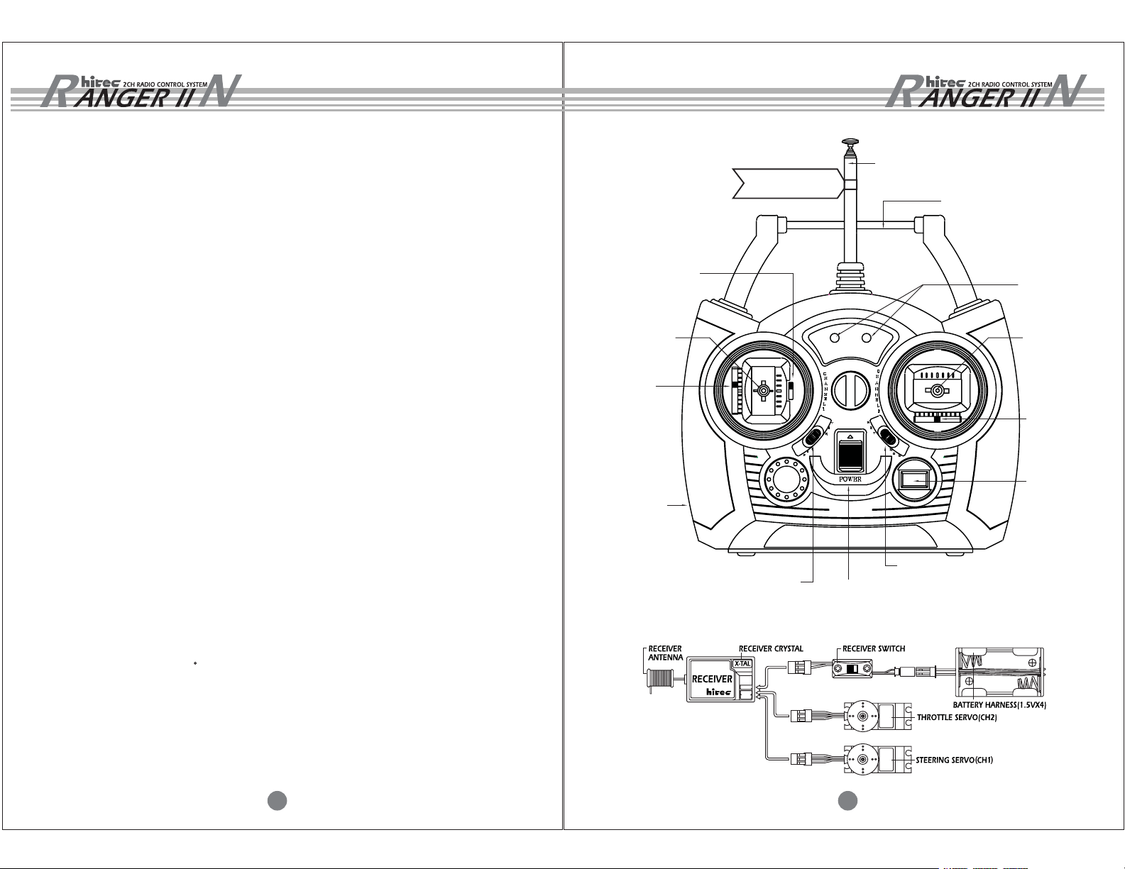
NEUTRAL POSITION
ADJUSTMENT LEVER
FREQUENCY FLAG
TRANSMITTER
ANTENNA
CARRYING HANDLE
POWER L.E.D
FEATURES AND SPECIFICATIONS
A. TRANSMITTER
- SUPER-HETERODYNE DIGITAL PROPORTIONAL FOR EXTRA LONG RANGE
- CRYSTAL INTERCHANGEABLE
- ALL CHANNEL SERVO REVERSING SWITCHES
- CHARGER CONNECTOR FOR NI-CAD BATTERIES(8CELL 9.6V)
- LOW BATTERY WARNING L.E.D INDICATOR FOR BATTERY POWER
- NEUTRAL POSITION ADJUSTMENT FOR THROTTLE
- ALL SMT CIRCUITRY
B. RECEIVER
- BUILT IN B.E.C (BATTERY ELIMINATOR CIRCUIT)
- CRYSTAL INTERCHANGEABLE
- SIZE AND WEIGHT
SIZE : 53 X 35 X 19(mm) (2.1" X 0.8" X 1.4") , WEIGHT : 28g (0.99oz)
C. SERVO
- HEAVY-DUTY SUPER HORN
- DUST RESISTANT DESIGN
- HIGH SPEED : 0.19sec/60
- HIGH TORQUE : 3.0kg.cm(41.66oz.in)
- HI-TEC CUSTOM CHIP FOR NARROW DEADBAND
- ALL SMT CIRCUITRY
THROTTLE
CONTROL STICK
THROTTLE
TRIM LEVER
CHARGING
JACK
THROTTLE SERVO
REVERSE SWITCH
POWER ON/OFF
SWITCH
STEERING
CONTROL STICK
STEERING TRIM
LEVER
TRANSMITTER
X-TAL
STEERING SERVO REVERSE SWITCH
CRYSTAL
2 3
Page 3

Set-up and installation of your new Ranger 2N
Please read the following section carefully before
attempting to install the Ranger 2N system
BATTERY INSTALLATION
1. The transmitter requires eight and the receiver battery pack needs four
AA size batteries. These can be Alkaline or Ni-cad cells. If you choose to
install Ni-cad batteries, the optional CG-25A(110V)or CG-22(220V)
Hitec overnight wall charger can be used to re-charge them.
2. When loading the batteries, make sure the receiver and transmitter switches
are in the "off" position.
3. Open the battery door in the back of the transmitter by squeezing the tab on the
bottom of the battery door and lifting up.
4. Load batteries into the appropriate slots, taking care to install according to the
proper polarity.
RADIO SYSTEM INSTALLATION
When installing the system in the model of your choice, please follow the
detailed instructions found in the model kit.
1. Install the receiver to protect it from vibration and potential crash damage.
2. Typically one servo will be used for the steering and the other servo will be
used to operate a mechanical speed control, or not used at all and an optional
electronic speed control will be used.
3. If your vehicle is electric, there will be a proportional speed control you will wish
to use. If your speed control is mechanical, it will require a servo to operate it.
The battery and switch harness found in the kit must also be used to provide the
receiver with power.
4. Should your model use an electronic speed control that has the option of the
B.E.C. circuit (battery eliminator circuit), this feature will eliminate the receiver
battery and use the motor battery to feed the receiver and servos through the
speed control.
BATTERY COVER
PRESS BOTTOM AND
OPEN UPWARD
8 AA SIZE BATTERY. BE
CAREFUL TO LOAD RIGHT
DIRECTION OF BATTERIES( + - )
5. Replace the battery door and turn the power "on". If the batteries are fresh and
charged, the green L.E.D. will be lit. Should the battery power drop to an unacceptable
level, the red L.E.D. will glow, warning the user of impending failure. At this point,
replace the alkaline cells or charge the batteries if they are Ni-cads.
4 5
(Electronic Speed Control)
5. Please refer to the instructions that accompany your electronic
speed control for installation.
Page 4

OPERATION CHECK HELPFUL HINTS
1. Plug the switch harness and servo connectors into the proper slots.
The connectors are polarized, so they will fit into the receiver one way only.
NEVER USE EXCESSIVE FORCE TO PLUG IN OR PULL OUT CONNECTORS.
2. Always turn the transmitter power switch "on" first, before the receiver switch to
avoid damaging your equipment.
3. Move the trim levers to the "neutral" position.
4. Check to see the servos move in the proper direction when the joysticks are moved.
If you wish to change the direction of rotation, use the servo reversing
switches on the front of the radio.
5. If you wish to have more forward throttle stick movement, push down the neutral
position adjustment lever, this will give 30% more forward movement.
NORMAL POSITION : FORWARD : BACKWARD = 50 : 50
Antenna
Both the transmitter and the receiver antenna must be fully extended when in use.
Do not cut off any excess receiver antenna wire or bundle it up as this will cut down
on the operating range of the system.
Changing Frequency
Hitec offers receiver and transmitter crystals to be used in changing the frequency of
your Ranger 2N system. Caution: The frequency can be changed only within the
same band, you cannot change from 75MHz to 72 or 27MHz just by changing crystals.
Water, Dust and Fuel
Take suitable measures to protect your system from water, dust, oil and fuel.
Servo Linkage
Install your linkages to be free from binding and slop. If you hear severe "humming"
from the servo, it is an indication the servo is working too hard and the geometry
of the linkage should be adjusted.
Throttle Ratchet
The spring mechanism on the throttle stick may be disconnected and an optional
ratchet part # 58314 is available to fit on the throttle gimbal to facilitate a ratchet
effect with detents.
LEVER DOWN : FORWARD : BACKWARD = 70: 30
Congratulations again and have fun!
6 7
 Loading...