

Page 1
V30 GNSS RTK System Manual
Manual
V30 GNSS RTK System
Manual
Manual Revision
Revision
Date
Feb.2014 2
Revision
Level
Hi-Target Surveying Instrument Co., Ltd.
V30 GNSS RTK System
All Rights Reserved
Description
I
Page 2

V30 GNSS RTK System Manual
Content
Preface ..................................................................................... 1
Instruction .......................................................................... 2
Relative Information .......................................................... 2
Your Suggestions ............................................................... 2
Summary ................................................................................. 3
Introduction ........................................................................ 4
Product Features ................................................................. 5
Usage and Notes ................................................................ 5
Receiver Introduction ............................................................ 7
Introduction ........................................................................ 8
Receiver Appearance ......................................................... 8
Control Panel ..................................................................... 9
Upper Cover ..................................................................... 10
Lower Cover ..................................................................... 11
Communica t i on Module .................................................. 12
Battery .............................................................................. 13
Environmental Requirement ............................................ 14
Electrical Interference ...................................................... 15
General Operations ............................................................. 16
Introduction ...................................................................... 17
Button functions ............................................................... 18
II
Page 3

V30 GNSS RTK System Manual
Led Status Instructions ..................................................... 21
Turn On/Off Receiver ...................................................... 27
Static Data Storage ........................................................... 27
RTK Data Storage ............................................................ 27
Reset Receiver ................................................................. 28
Module checking .............................................................. 28
Format Receiver ............................................................... 28
Power Supply System ...................................................... 29
Communication Module .................................................. 36
SIM Card/ USIM Card ..................................................... 40
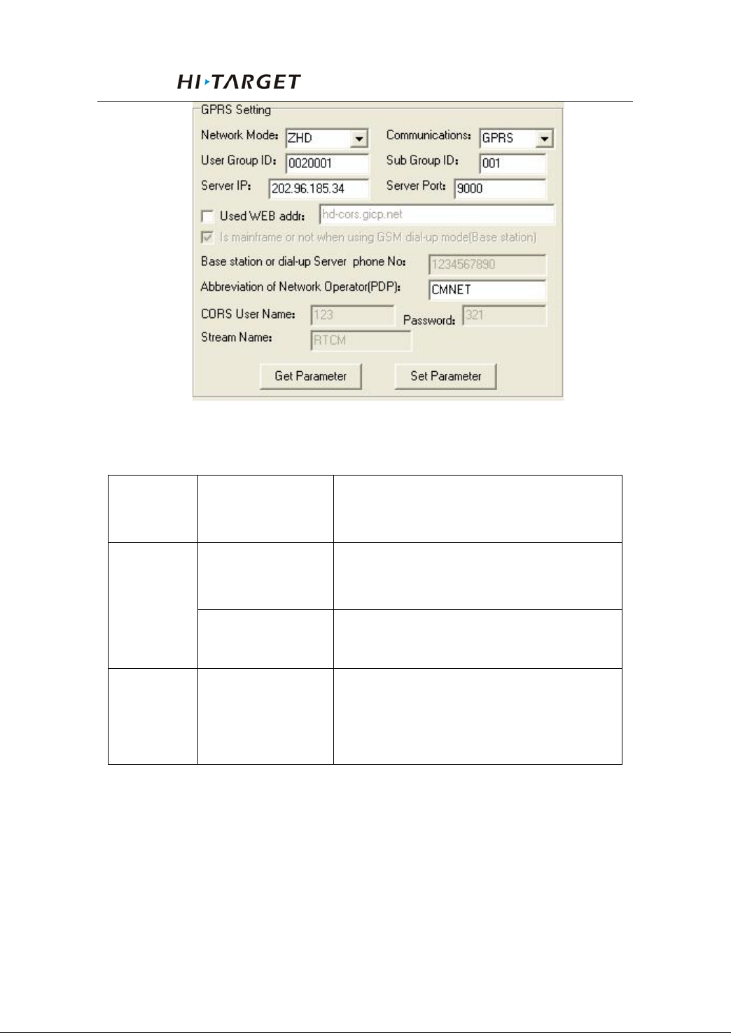
Firmware .......................................................................... 41
Configuration of Fieldwork ................................................ 44
Introduction ...................................................................... 45
Diagram for base working ............................................... 45
Diagram for rover working .............................................. 48
Fast Operation Guide ....................................................... 49
Static Collecting ................................................................... 53
Instruction ........................................................................ 54
The procedure of V30 static survey ................................. 54
Download data w i t h USB drive ....................................... 55
Management software operation for static survey ........... 55
Technical Parameters .......................................................... 58
Introduction ...................................................................... 59
III
Page 4

V30 GNSS RTK System Manual
Receiver ........................................................................... 59
UHF Radio Communication ............................................ 60
3G/GPRS Network Com m uni ca ti on ............................... 62
Ports ................................................................................. 62
Function Key and LED .................................................... 62
Intelligent Voice Module ................................................. 62
Accuracy .......................................................................... 62
Physical Feature ............................................................... 63
Environment ..................................................................... 63
Ports and Main Accessory ................................................... 64
Introduction ...................................................................... 65
Five-pin Port and Eight-pin Port ...................................... 65
Differential Antenna ........................................................ 67
Y Type Data Cable ........................................................... 68
Regulatory Information ...................................................... 70
Notes ................................................................................ 71
IV
Page 5

V30 GNSS RTK System Manual
1
Preface
Chapter Instruction
■ Instruction
■ Relative Information
■ Your Sugges tions
C H A P T E R
1
Page 6

Perface
Instruction
Welcome to Hi-Target V30 Series GNSS RTK system
manual. This manual is designed for V30 GNSS RTK system,
and use V30 GNSS RTK as an example to explain the
installation, setup, and usage of the GNSS RTK system.
If you have used other GNSS RTK system before,
Hi-Target suggests you read this manual carefully and this
manual will help you to understand our V30 GNSS RTK
system easil y. If yo u do not familiar wi th GNSS RTK, please
check Hi-Target website: http://www.hi-target.com.cn/en/
Relative Information
You can get the manual from: 1, the complement CD
when purchasing Hi-Target V30 equipment. You can get this
manual from folder named Manual; 2, Download from
Hi-Target website, Go to “Support” -> “Manual” ->
“Surveying Products”.
Your Suggestions
If you have an y suggestions or co mments on the manual,
please feel free to contact us, it will help us to improve our
manual quality greatly.
2
Page 7

V30 GNSS RTK System Manual
2
Summary
Chapter Introduction
■ Introduction
■ Products Features
■ Usage and Notes
C H A P T E R
3
Page 8

Summary
Introduction
V30 GNSS RTK system adopts modularized design, so as
to enable users to change into different differential
transmission modules according to various requirements.
Those are traditional radio transmission, GPRS and 3G
communication functions. Meanwhile the designed
self-diagnosis function can automatically check the working
status of al l hardware and softw are of the V30 receiver wh ile
working, and arouse the problem part by its intelligent voice
messenger in case of some problem.
Data collection controller can be connected with receiver
mainframe via Bluetooth or cable; built-in high-capacity
battery is suitable for long -time field work; static data can be
stored in the built-in memory card of receiver and downloaded
via USB port to your PC.
Tips: 1. V30 GNSS RTK system has many modules.
This manual does not represent standard
configuration. Users need to notify their own
requirements for the different configuration
due to different applications.
2. And before using, we sugges t users firstly to
check whether the package box i s damaged,
and then open careful and check whether
inner items matched with the order list of
their own. If there a re some missing or
damaging cases exist for products and
4
accessories, please contact with the local
Page 9

V30 GNSS RTK System Manual
distributor or Hi-Target Foreign Trade Dep.
Immediately.
3. Last but not least, please carefully read
manual before carrying, handling and using!
Product Features
1. BD970 mother board of Pacific Crest, a Trimble Company,
multi-satellite, multi-system kernel.
2. Built-in transmit-receive UHF, exchangeable Base and
Rover.
3. The radio power is adjustable to be 0.1w, 1w, 2w.
4. 1+X multi-module communication units.
5. PCC Radio module (optional) compatible with
Trimble/Leica RTK.
6. Double battery capaci t y as 4400mAh, 12 ho ur s for RTK
operating.
7. The highest performance in waterproof, dustproof and
anti-drop.
8. Adjustable to be single GNSS system or multi-GNSS
system: GPS, GLONASS, GALILEO.
Usage and Notes
Although V30 receiver using chemical and impact
resistance mat erial, b ut necessar y taking car e and main tenance
is still required for such a precise instrument.
5
Page 10

Summary
Warning: The receiver must be used and stored
in the specified temperature. More details
please refer to Chapter 7: Technical
Parameters.
To ensure the qual ity of conti nuous track ing sat ellites an d
signals, surveying work should be in open air, while there
should no any obstacle in space above 15° altitude angle; in
order to r edu ce all ki nds o f elect rical int erfer ence t o th e GN SS
satellite signals. Besides, there should not be strong electrical
interference around within about 200m range, such as the
television tower, microwave stations, high voltage
transmission line. Also, in order to avoid or reduce the
occurrence o f multi-path effect, stations should be away from
terrain or geographical objects, which will strong effect
electrical signal, such as high-rise buildings, big pool, etc.
6
Page 11

V30 GNSS RTK System Manual
3
Receiver Introduction
Chapter Introduction
■ Introduction
■ Receiver Appearance
C H A P T E R
■ Control Panel
■ Upper Cover
■ Lower Cover
■ Communication Modul e
■ Battery
■ Environmental Requirement
■ Electric Interference
7
Page 12
Receiver Introduction
Lower Cover
Introduction
This Chapt er mainly in troduces V30 receiv er appearan ce,
buttons and indicator led and so o n.
Receiver Appearance
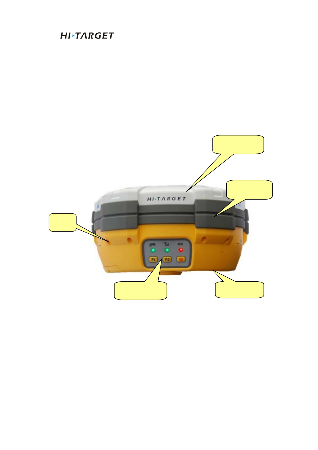
Receiver Appearance mainly including 4 parts: upper
cover, lower cover, guard collar and control panel, as Figure
3-1
Screw
Upper Cover
Guard Collar
Control Panel
Figure 3-1 Receiver Appearance
8
Page 13
V30 GNSS RTK System Manual
Control Panel
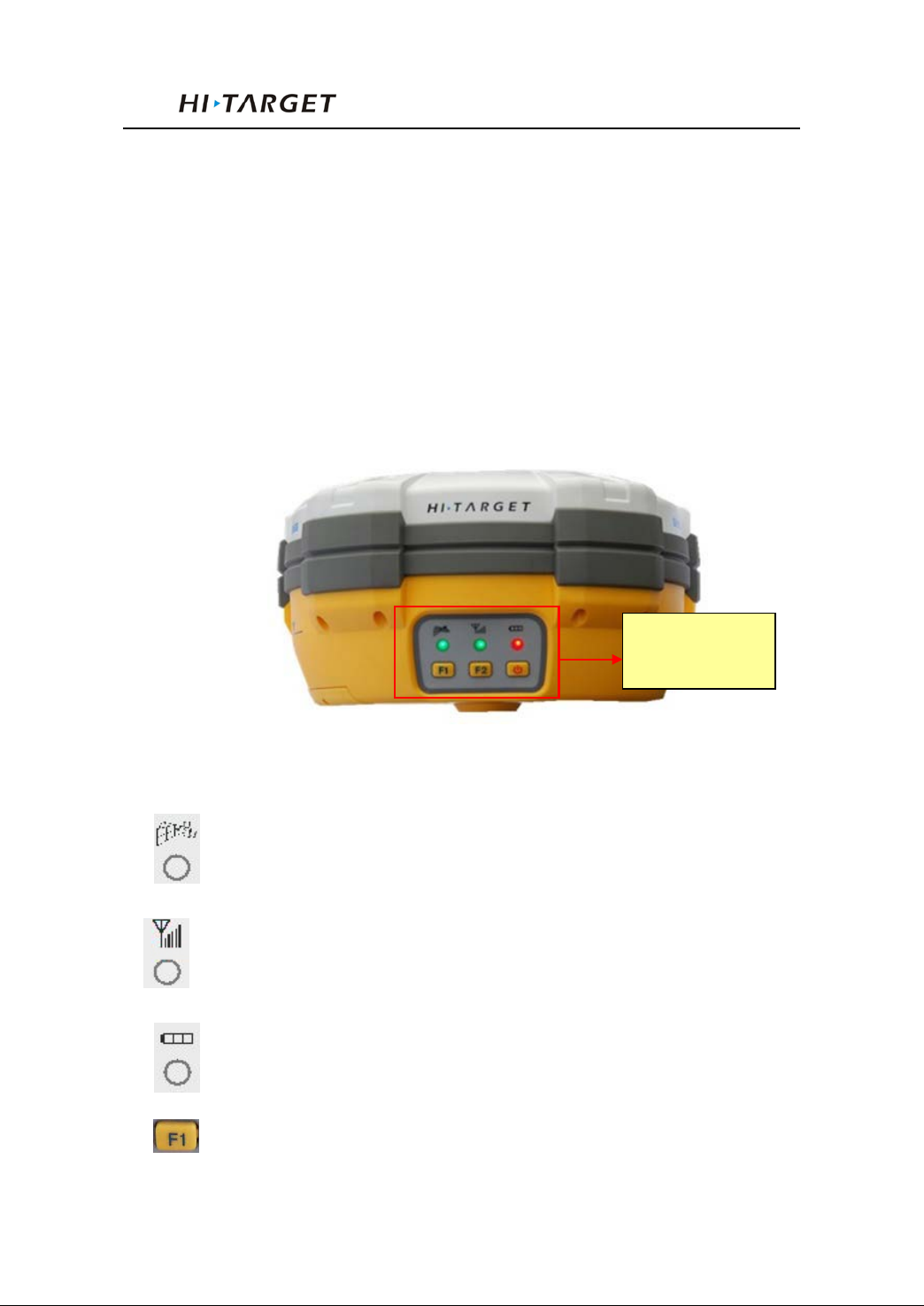
Figure 3-2, in the middle of red frame of V30 receiver is
control panel. And the control panel contains the F1 key
(function key 1), F2 key (function key 2) and the power button,
3 indicator leds which are respectively satellite led, the statu s
led (dual-color led ), the power led (dual-color led). The
simple three buttons include all the features setting of the v30
receiver.
Control Panel
Figure 3-2 Control Panel
Satellite led(green led)
Status led(red-green dual-color led)
Power led(red-green dual-color led)
Function Key: settings of working mode, UHF radio
9
Page 14
Receiver Introduction
transmitting power,satellite elevation angle,automatically
base setting, reset receiver and so on.
Function Key: settings of data link, UHF radio channels,
collection interval, back to original setting.
Power Key: setting confirmation, automatically base
setting and so on.
Upper Cover
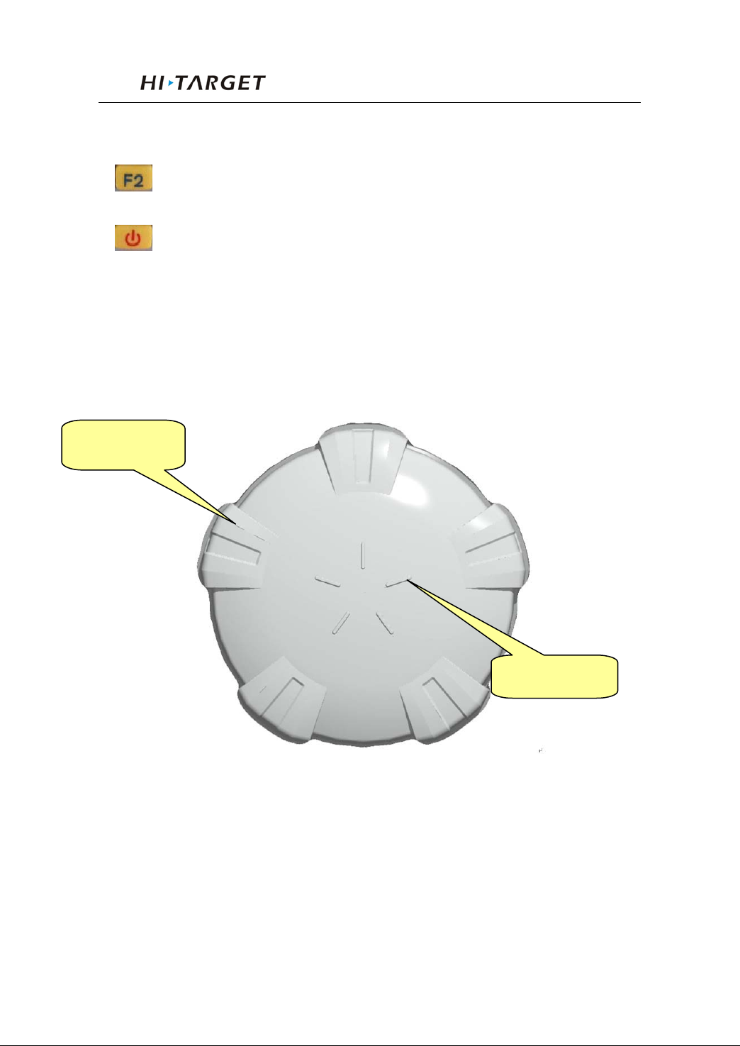
Figure 3-3 i ndicates the upper cover of V30 receiver, the
main function o f which is anti-dr op and a nti-scratch.
Raised Plate
Raised Point
Figure 3-3 Upper Cover
Raised Point: anti-wear point to avoid instrument being
scratched
Raised Plate: 5 raised plates can avoid wear-out and falling
10
Page 15
V30 GNSS RTK System Manual
Module position
Module Connector
Joint Nut
Lower Cover
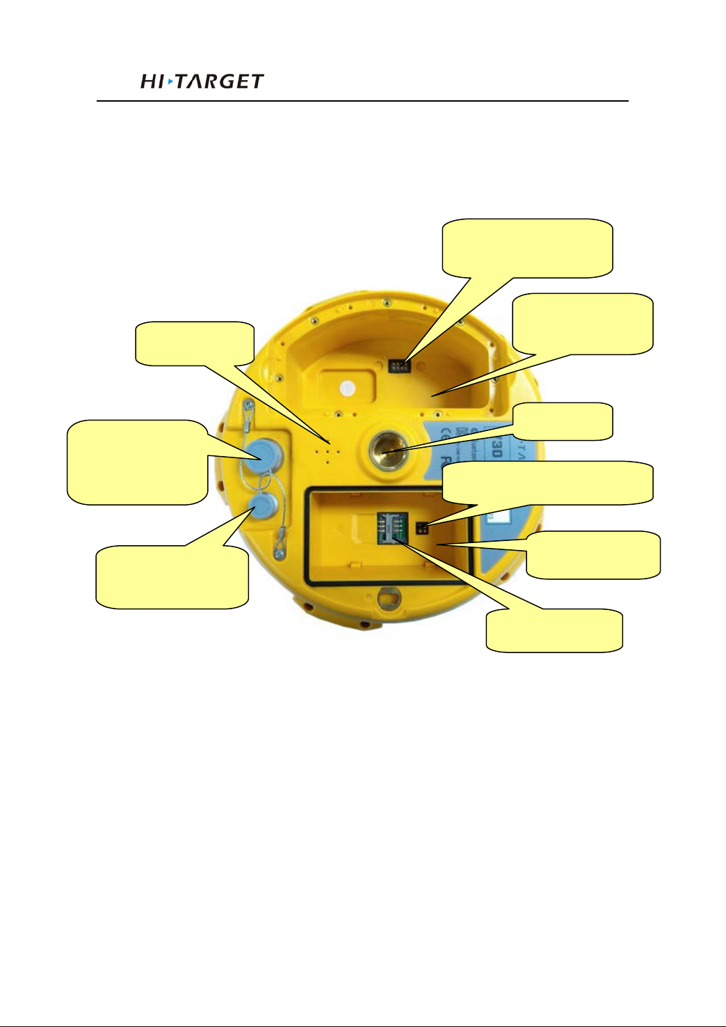
As figure 3-4, lower cover of V30 i ncludes communicat ion
module slot, battery groove, five-pin port, eight-pin port,
loudspeaker and so on.
Loudspeaker
Eight-pin Port
and Protection
Plug
Five-pin Port and
Protection Plug
Figure 3-4 Lower Cover
Communication
Communication
SLC Power Supply Block
Battery Groove
SIM Card Slot
Communication Module: according to different
Communication module connector: connect
Battery Groove: install 4400mAh lithi um battery
Five-pin port: connect mai nf ram e wi th ext ern al d ata l in k o r
requirements, traditional UHF radio, GPRS and 3G
communica t i on module can be chosen
communica t i on module and mainframe
11
Page 16
Receiver Introduction
with external power supply
Eight-pin Port: connect V30 receiver with computer, or
controller for data download and delete
Protection Plug: anti-dust and waterproof for socket
SIM card slot: when choose GSM communication, install
SIM card.
Joint Nut: fix inst rument with tribrach and centeri ng pole.
Loudspeaker: voice broadcast for real-time operation and
status.
Tips: 1. if no need to use five-pin port,
eight-pin port and differential
antenna port, please affix rubber
plugs to achieve waterproof and
dustproof.
2. when water comes in loudspeaker,
maybe it becomes silent or sound
hoarse. But it will be back to
normal after drying.
Communication Module
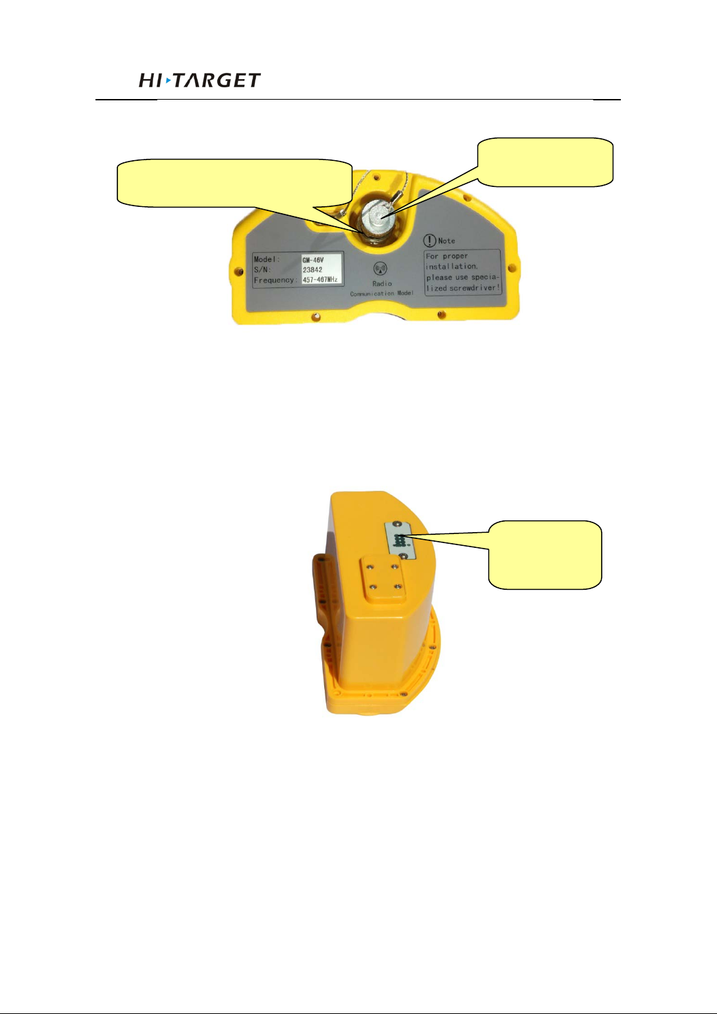
As figure 3-5 of the appearance of communication
module, accor ding to different requirements, V3 0 receiver can
be installed with traditional UHF radio, GPRS and 3G
communication module.
12
Page 17
V30 GNSS RTK System Manual
Difference Antenna Connector
Figure 3-5 Communication Module 1
Protection Plug
Battery
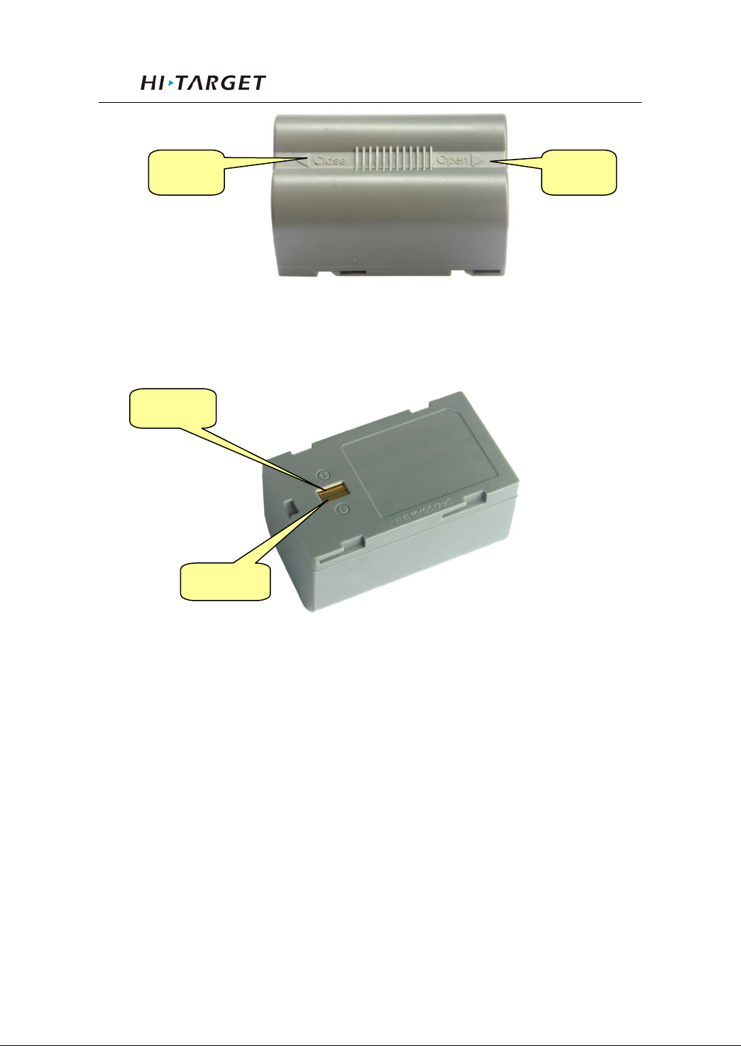
As figure 3-7, the appearance of 4400mAh lithium
Battery
Module
Connector
Figure 3-6 Communication Module 2
13
Page 18
Receiver Introduction
Anode
Cathode
Close
Open
Figure 3-7 Battery Front
Figure 3-8 Battery Back
Environmental Requirement
Even though V30 receiver uses waterproof materials,
maintaining in a dry environment is still helpful. In order to
improve the stability, and duration of the receiver, please avoid
exposing the re ceiver in extreme environments, such as:
Moist
Temperature higher than 65 Celsius degrees
Tempera t ur e lower than -40 Celsius degrees
Corrosive liquid or gas
14
Page 19

V30 GNSS RTK System Manual
Electrical Interference
Do not place GNSS receiver around a strong power
interference signal source, such as:
Oil duct ( spark plug )
Television and computer monitor
Generator
Electric motor
DC-AC power conversion equipment
Fluorescent Light
Power switcher
15
Page 20

General Operations
4
General Operations
Chapter Introduction
■ Introduction
■ Button Functions
■ Led Status Instructions
C H A P T E R
■ Turn On/Off Receiver
■ Static Data Storage
■ RTK Data Storage
■ Reset Receiver
■ Back to Original Settings
■ Format Receiver
■ Power Supply System
■ Communication Modul e
■ SIM Card/ USIM Card
■ Firmware
16
Page 21
V30 GNSS RTK System Manual
Double click the button while the
Introduction
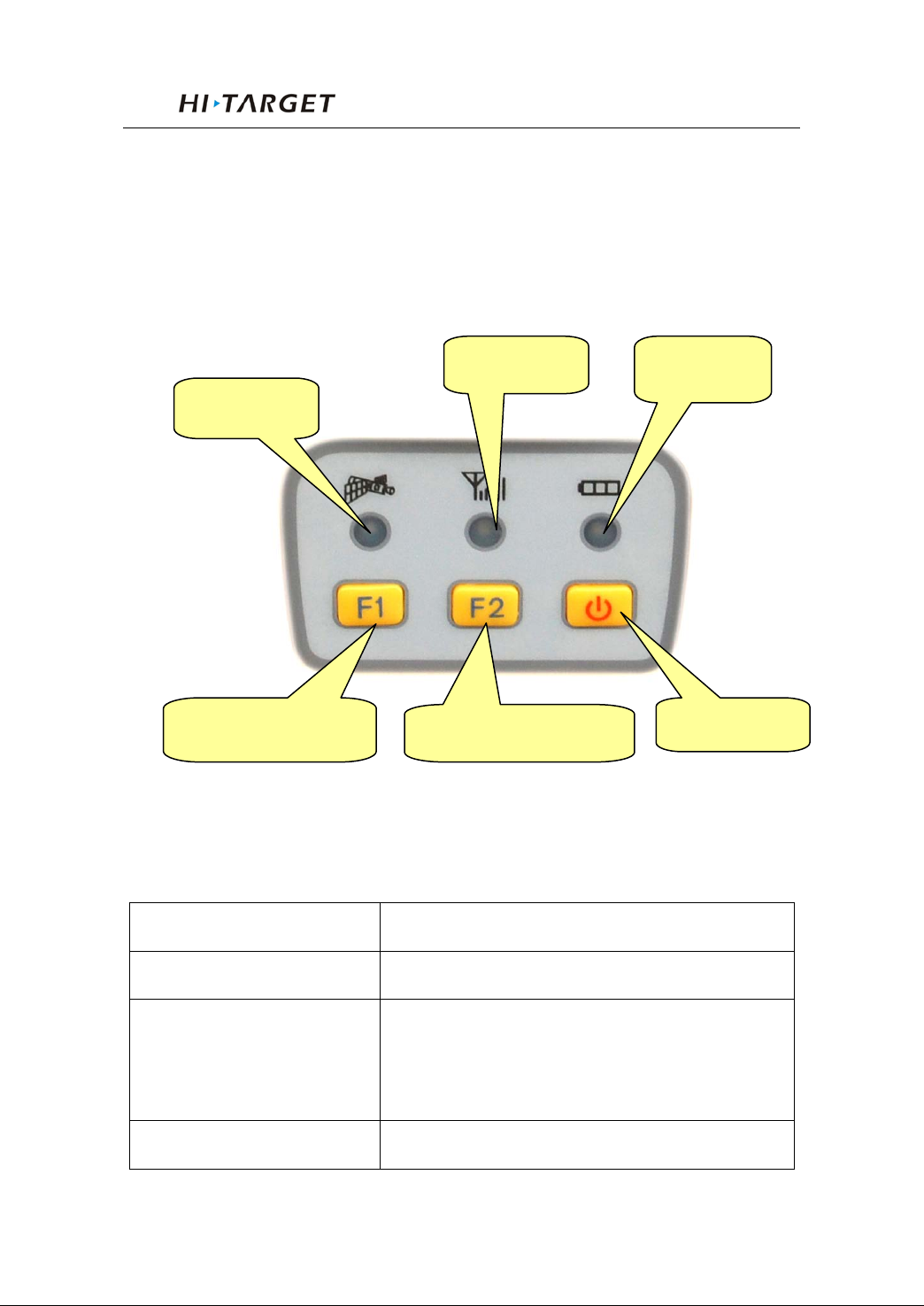
Most of the operat i ons of V30 receive r can be done by the
three buttons on the mainframe panel.
Buttons on the pa nel:
Satellite Led
Function Button F1
Status Led
Function Button F2
Figure4-1 Mainframe Panel
Power Led
Power Button
Explanations of buttons operations and leds hints as
below:
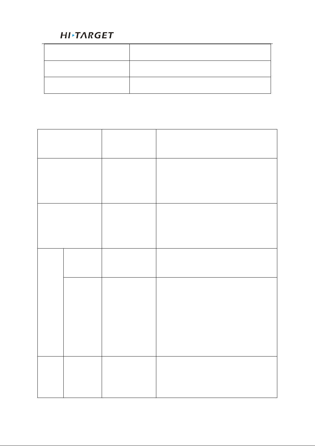
Operations Explanation
Single click button Press a button less than 0.5 second
Double click button
clicking interval should be between 0.2 to 1
second
Long pressing button Pressing button more than 3 second
17
Page 22
General Operations
Then single click F2 to choose the
Long pressing
F1 to choose channelby minus 10;or
single click F2 tochoose channel by
to be 5 degrees,10 degrees, or 15
Super long pressing Pressing button more than 6 second
Slow flash of led Flashing interval more than 0.5 second
Fast flash of led Flashing interval less than 0.3 second
Button functions
Button
Factions
operations
Introduction
Then single click F1 to choose the
UHF
mode
Work mode
Data link
Power
Channel
Double click F1
Double click F2
F1
Long pressing
F2
receiver work mode among “base”,
“rover”, “static”
data link among “GSM”, “UHF”,
“External”
Then single click F1 to set the transmit
power to be high, middle, or low
Then single click F1 to choose channel
by minus 1; or you can long pressing
plus 1; or youcan long pressing F2 to
choose channel by plus 10
Elevation
Static
angle
18
Long pressing
F1
Single press F1 to set elevation angle
degrees
Page 23

V30 GNSS RTK System Manual
Long pressing
Static data
Single press
Then the receiver will speak out its
current work mode, data link, radio
transmit power, channel; meanwhile
the power led will flash to hints its
to turn
1 while than press power
receiver until hearing “Dingdong”.
Then the receiver speak out its
Back receiver to
Then it will automatically rectify,
correct and reset to the original
Check currect
button in
receiver speaks
the same time the
power led flashing times hints the
power status and the satellites led
flashing times hints tracked satellites
For base in external mode: receiver
Collection
interval
collection
Confirm setting
Auto-set base
F2
Double click F2
power button
F1+Power
button
receiver
Single press F2 to set collectioninterval
to be 1s,5s,10s
Double click F2 to start collecting
static data
power status
Press F
buttonat the same time to turn on the
current status.
Reset receiver
original settings
work status
Long press F1 Reset the mother board
Long press F2
Single click an y
non-settings
status
settings.
For static mode :
out“static”, collection interval,
elevation angel; at
number
19
Page 24
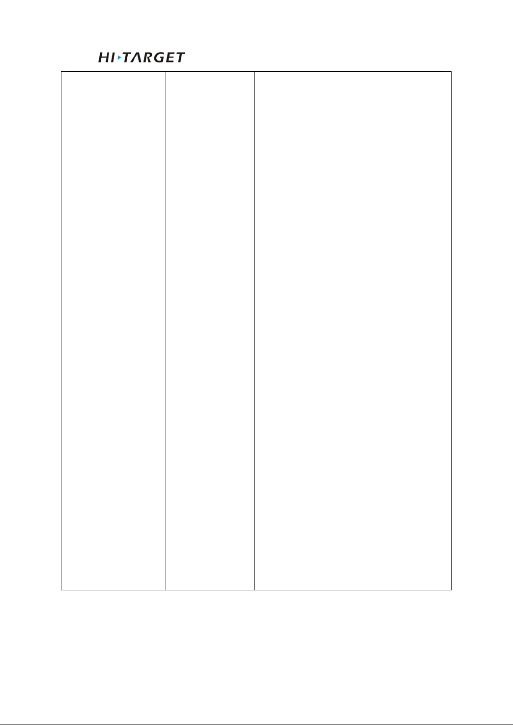
General Operations
speaks out “external, base”; at the
For rover in external mode: receiver
speaks out “external, rover”; at the
For base in internal UHF: receiver
speaks out “UHF, base, channel **,
led flashing times hints the power
For rover in internal UHF: receiver
speaks out “UHF, base, channel **” ;
For base in GSM mode: receiver
For rover in GSM mode: receiver
same time the power led flashing times
hints the power status
same time the power led flashing times
hints the power status
power *”; at the same time the power
status
at the same time the power led flashing
times hints the power status
speaks out “GSM, base”; at the same
time the power led flashing times hints
the power status
20
speaks out “GSM, rover”; at the same
time the power led flashing times hints
the power status
Page 25
V30 GNSS RTK System Manual
Power led
normal voltage: internal battery voltage >7.6V,
Power led
Power status hints: one or four times of one
Status led
GSM module has been connected to internet
been connected to internet
led for
receiving corrections for rover while transmitting
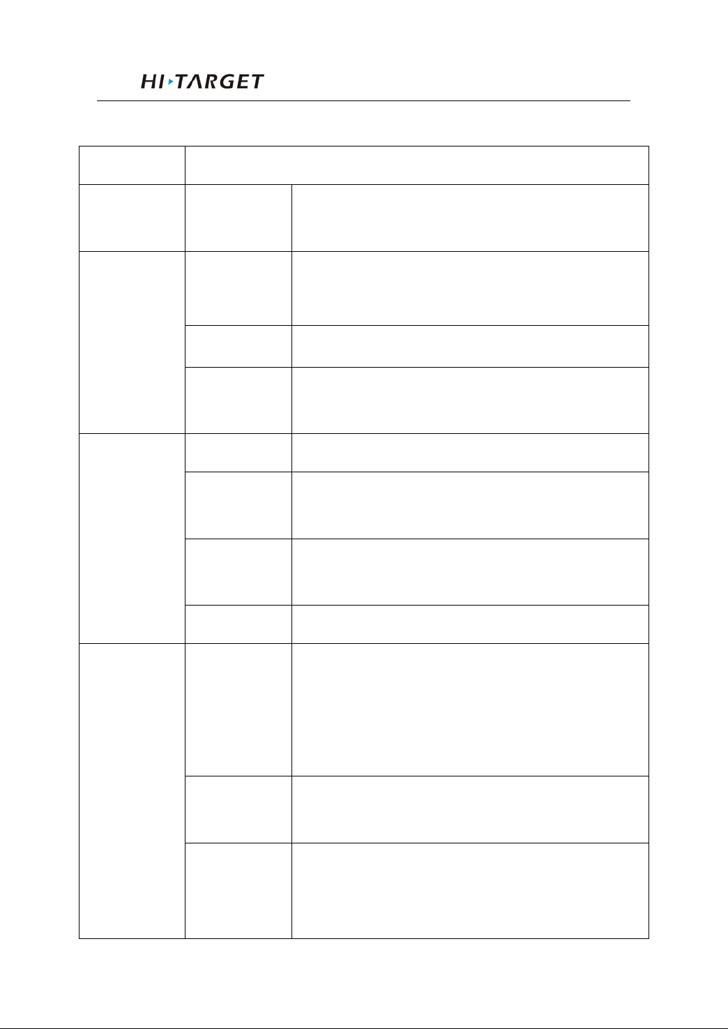
Led Status Instructions
Led Instruction
In
Always on
(yellow)
Always on
external battery voltage >12.6V
In normal voltage: 7.2V<internal battery voltage
≤7.6V, 11V<external battery voltage ≤12.6V
(red)
(green led for
status)
Slow flash
Fast flash
Off In external radio, UHF mode, and static mode
Always on
Slow flash
Fast flash GSM module is trying to connect to internet server
Slow flash
Low power-pressure: inter≤7.2V,external≤11V
minute
server successfully
GSM module has
successfully
1. getting correction data via GSM or radio (only
for base)
Data led (red
status)
Fast flash
Always on
2. collection static data in static mode
Error in static mode (typically for no more flash
memory)
Communication module in error for getting data,
mainly resulted by problem in module so that no
data output
21
Page 26
General Operations
Satellite led
Always on More than 4 satellites tracked successfully
Slow flash Loss satellites and try re-tracking
1. mother board error resulting in no data output
(green)
Off
while resetting receiver
2. mother board error resulting in no data output
while in static mode
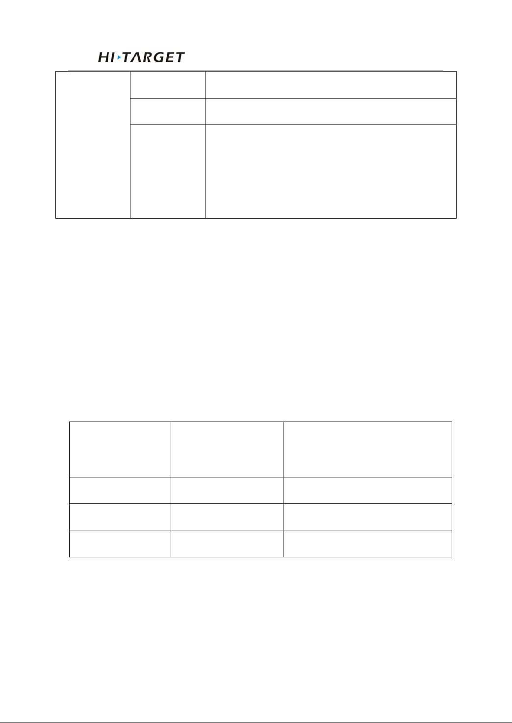
Led displaying in different mode:
1. Work Mode (double click F1 to enter work mode setting,
then single click F1 to choose work modes among static,
rover and base. After that single click power button to
confirm the current setting. If no confirming within 10
seconds, th e receiver will aut omatically confir m the current
settings.):
● on ○ off
Satellite led
Mode
(green led)
Status led
(green led of the dual-color led)
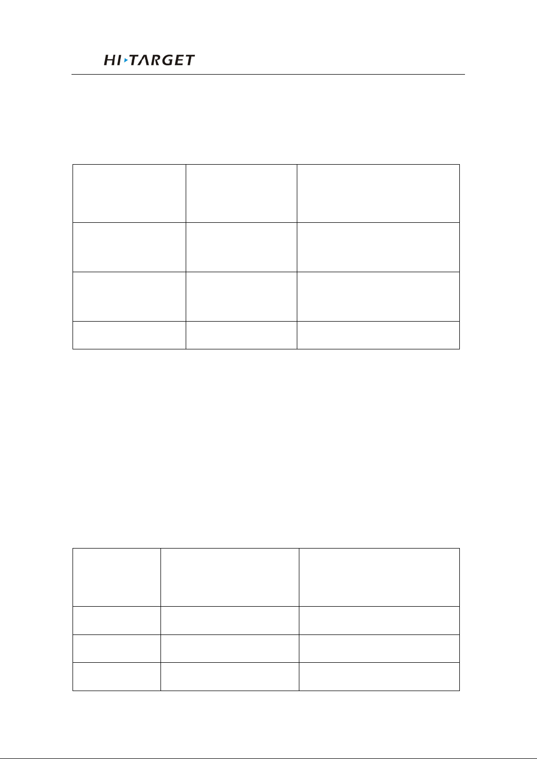
2. Data Link (double click F2 to enter data link setting, then
single click F2 to choose from GSM, UHF, and external, After
that single click power button to confirm the current setting. If
Base ● ○
Rover ○ ●
Static ● ●
22
Page 27
V30 GNSS RTK System Manual
no confirming within 10 seconds, the receiver will
automatically confirm the current settings.):
● on ○ off
Satellite led
Data link
(green led)
UHF/GSM/CMDA
● ○
module
Internal
○ ●
GSM/CMDA
External ● ●
Status led
(green led of dual-color led)
3. Transmitting Power (must be set in UHF mode. Long press
F1 to enter tr ansmitting power setti ng, then single click F1 to
choose among high, middle, and low. After that single click
power button to confirm. If no confirming within 10 seconds,
the receiver will automatically confirm the current se tt ings.):
● on ○ off
Satellite led
Choice
(green led)
Low ● ○
Middle ○ ●
High ● ●
Status led
(green led of dual-color led)
23
Page 28
General Operations
(red led of
(red led of
(green led of
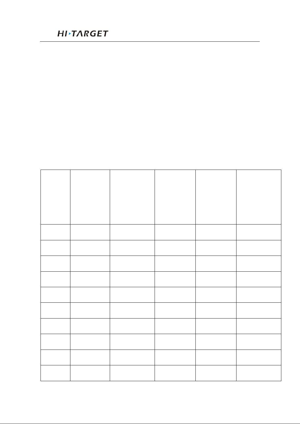
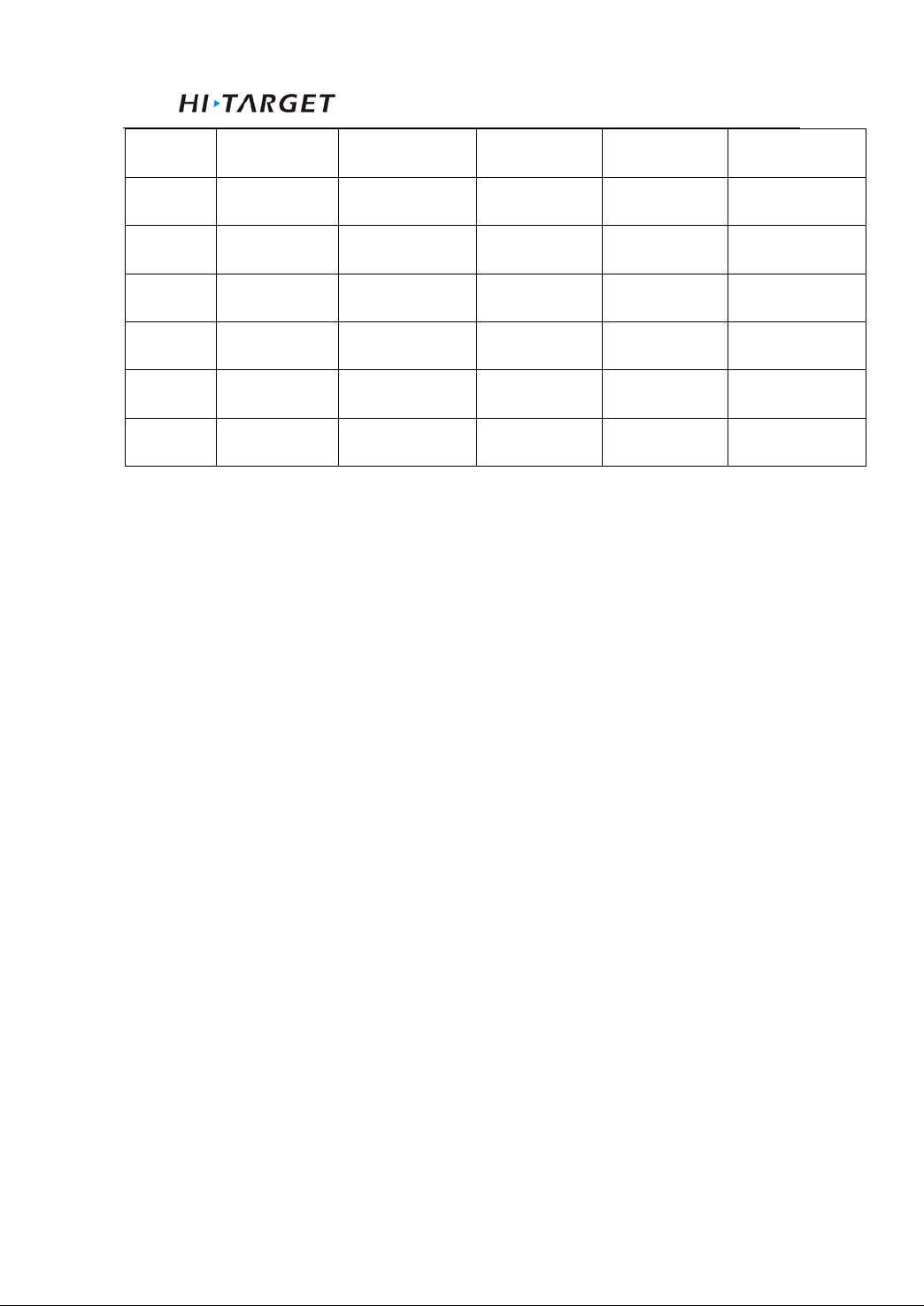
4. Radio Channel (must be in UHF mode. Long press F2 to
enter radio channel setting. Then single press F1 to choose
channel by minus 1; or long press F1 to choose channel by
minus 10; or single click F2 by plus 1; or long pres s F2 by plus
10. After that single click power button to confirm. If no
confirming within 10 seconds, the receiver will automatically
confirm the current settings.):
● on ○ off
Status led
Satellite led
Channel
(green led)
0 ○ ○ ○ ○ ○
1 ● ○ ○ ○ ○
2 ○ ● ○ ○ ○
3 ● ● ○ ○ ○
4 ○ ○ ● ○ ○
5 ● ○ ● ○ ○
6 ○ ● ● ○ ○
7 ● ● ● ○ ○
(green led of
dual-color
led)
Data led
dual-color
led)
Power led
dual-color
led)
Power led
dual-color
led)
8 ○ ○ ○ ● ○
9 ● ○ ○ ● ○
24
Page 29
V30 GNSS RTK System Manual
10 ○ ● ○ ● ○
11 ● ● ○ ● ○
12 ○ ○ ● ● ○
13 ● ○ ● ● ○
14 ○ ● ● ● ○
15 ● ● ● ● ○
more ○ ○ ○ ○ ●
25
Page 30
General Operations
5. Elevation Angle (must be in static work mode. Long press
F1 to enter elevation angle setting. Then single click F1 to
choose elev ation angle. Af ter that si ngle click pow er button t o
confirm. If no confirming within 10 seconds, the receiver will
automatically confirm the current settings.):
● on ○ off
Satellite led
Choice
(green led)
5 ● ○
10 ○ ●
15 ● ●
Status led
(green led of dual-color led)
6. Collection Interval (must be in static work mode. Long
press F2 to enter collection interval setting. Then single click
F2 to choos e collection interval. After that single cl ick power
button to confirm. If no confirming within 10 seconds, the
receiver will automatically confirm the current settings.)
● on ○ off
Satellite led
Choice
(green led)
1 ● ○
26
Status led
(green led of dual-color led)
Page 31
V30 GNSS RTK System Manual
Press power for
With turning on music, receiver
speeaks out the last settings of work
Long press
power button for
5 ○ ●
10 ● ●
Turn On/Off Receiver
Turn on
1 second
Turn off
3 seconds
All leds on
mode, data link etc.
All leds on With turning on music
Static Data Storage
The GNSS static data collected by V30 receiver will be
stored in its memory, in *.GNS format.
You can connect the V30 receiver with PC by USB port
of Y cable and then just copy the static data into your PC.
Note: in case of no more memory, the data l ed
(the middle led) will be fast flashing
while stopping the current static data
RTK Data Storage
The controller can be connected with the receiver via
Bluetooth or cable, the data will be stored in the memory of
the controller.
After fieldwork finished, you can connect the controller
with PC by the data cable, and then download the RTK data
collection.
27
Page 32

General Operations
from the contro l l er to PC by copyi ng.
Reset Receiver
Long press F1 button for more than 6 seconds to reset the
mother board.
Warning: reset receiver will make the next
tracking satellite time longer while
needs users to set receiver work
mode again.
Module checking
Long press F2 for more than 6 seconds to check the
module in current work mode.
Format Receiver
Format V30 receiver by Hi-Target V30 Receiver
Management Soft ware:
Connect V30 wi th PC by seria l por t of Y data cable
Turn on V30 rece iver
Choose right serial port and open port
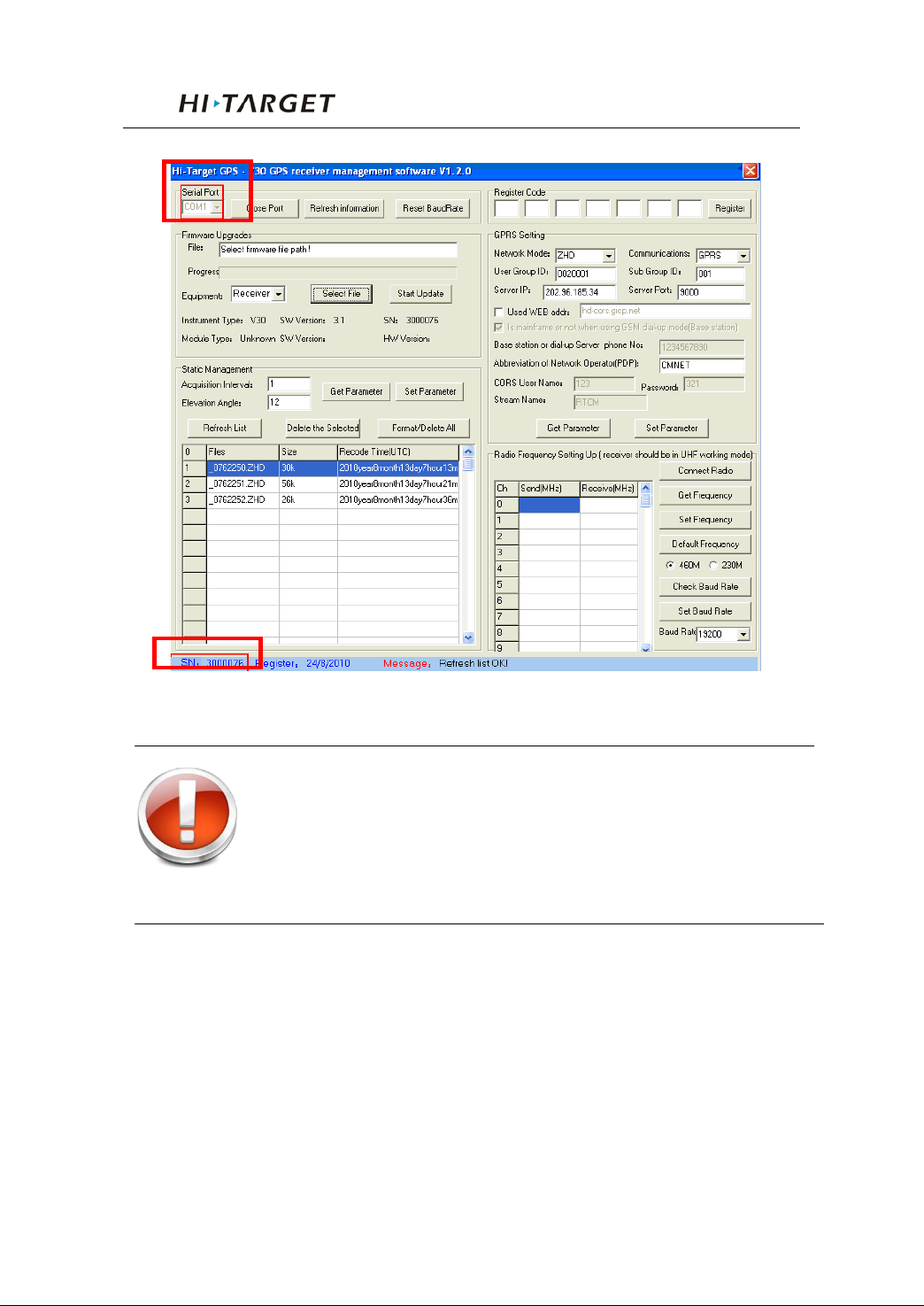
After con nect in g s uccess fu ll y as f ig ur e 4 -2: the S/N will be
showed in the bel ow
Click “Format/Delete All” to complete format receiver.
After this operation, all current data will be deleted forever.
28
Page 33
V30 GNSS RTK System Manual
Figure 4-2
Warning: Make sure all u sefu l dat a has been copi ed
to another pl ace for spare, becau se all data
will be deleted forever afte r this format.
Power Supply System
Assembly and Disa s sembly of Battery Cover
Assembly:
1. Firstly insert one side
29
Page 34
General Operations
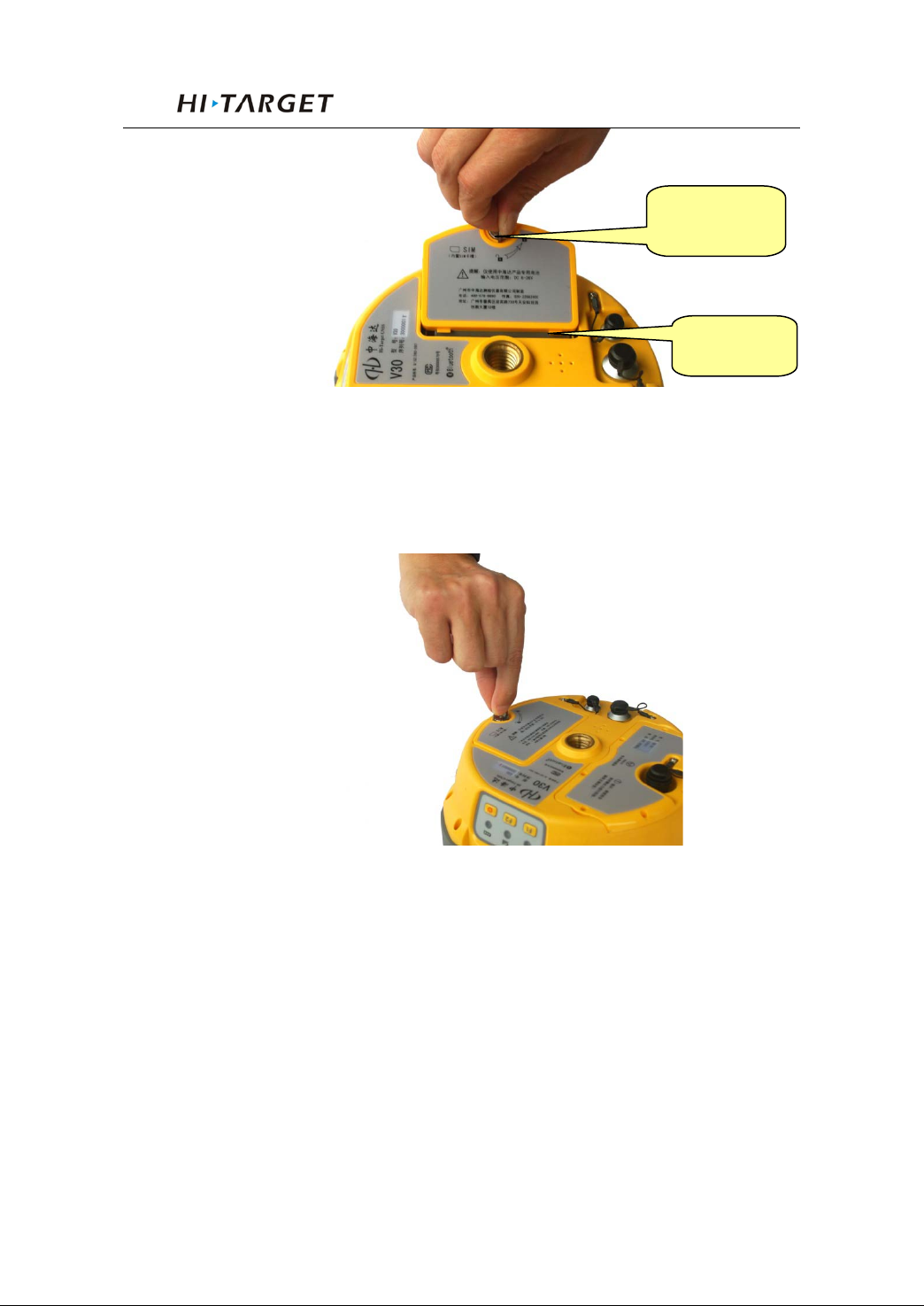
Metal lock
Fix slot
Figure 4-3
2. Turn the metal lock by 90° to the panel side and press it
to be ok.
30
Figure 4-4
Page 35
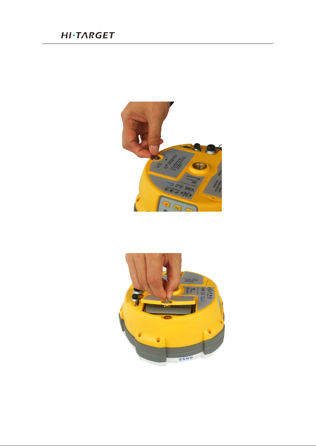
V30 GNSS RTK System Manual
Disassembly:
1. Pull the metal lock up and turn to the two ports direction
by 90°
Figure 4-5
2. Pull the metal lock to get off the battery cover
Figure 4-6
31
Page 36
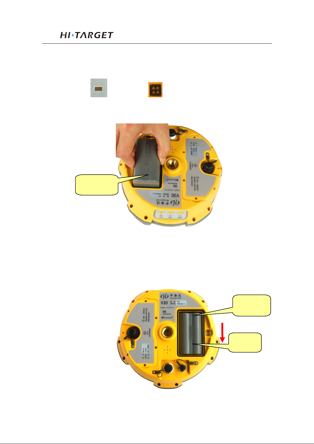
General Operations
Install and Uninstall Battery
Install:
1. Match with the in the battery slot to put in
the battery.
Open
Figure 4-7
2. Insert battery towards “Close” end (see red arrow) to
install it ok
Open
Close
Figure 4-8
32
Page 37
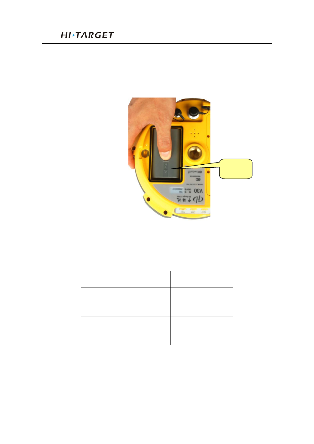
Uninstall:
Slide the battery towards to the “Open” end, and then pull
out battery is ok.
V30 GNSS RTK System Manual
Open
Figure 4-9
V30 Receiver Battery Name and Model
Name Model
4400mAh lithium
BL-4400
battery
V30 lithium battery
CL-4400
charger
33
Page 38
Power Supply
Power supply
port on the mainframe for external
General Operations
1. lithium battery;
Powe
r supply
way
Power range
2. eight-pin port and five-pin
power supply
6V ~ 36V
If use external power supply for V30 by the eight-pin port
and five-pin port on the mainframe, the power supply should
be 6~36V with current no less than 500 mAh.
When using both lithium battery and external battery, the
receiver will check the power pressure of both batteries and
choose the highe r one.
And please note that if use external power supply, must
use the specified external power supply from Hi-Target to
avoid any destroy to the receiver.
Note: usually one V30 lithium battery can last 13
hours for static, 12 hours for RTK while 9
hours for base in UHF work mode with 2
W internal radio. But the working time
will be decreased along with the more and
more charging times or in very low
temperature.
34
Page 39
V30 GNSS RTK System Manual
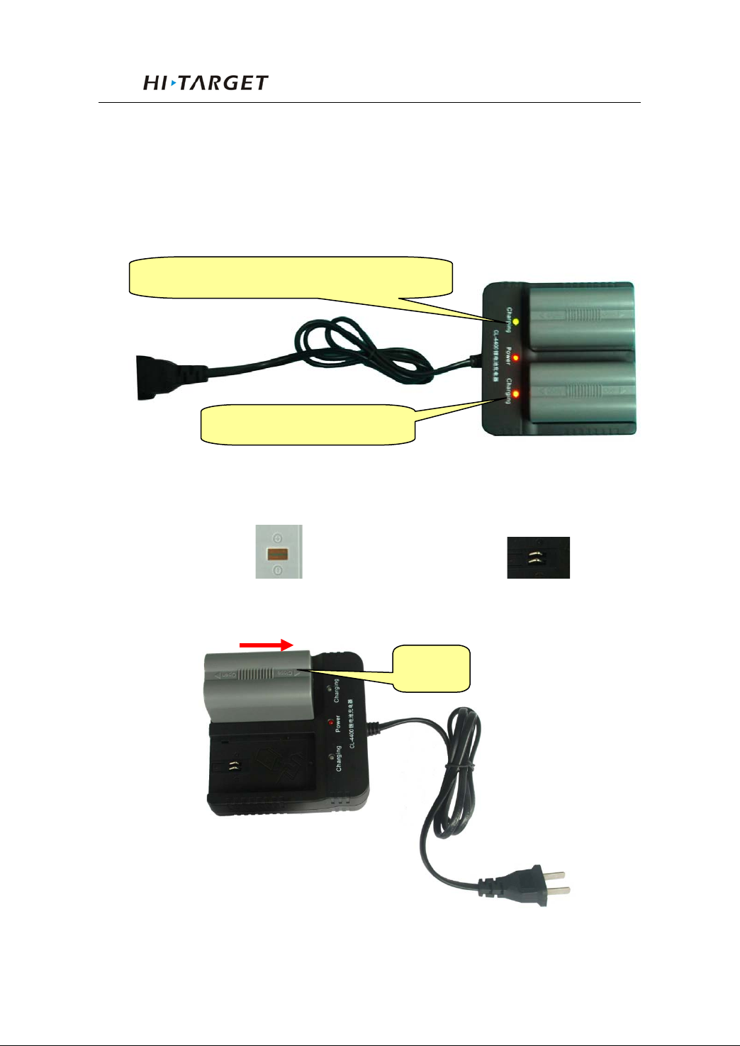
Green led for almost finishing charging
Red led for charging now
Battery charging
BL-4400 lithium battery must be charged in specified
CL-4400 charger of Hi-Target for about 6 hour s. The indi cator
led of the charger will be in red while charging, and then green
when charging finished.
Figure 4-10
Charging Operations
1. Matching the in the battery with in the
charger, put the battery in.
Close
Figure 4-11
35
Page 40
General Operations
470MHz radio, compatible with
430MHz radio, compatible with
2. Slide battery towards to “Close” end (as the above arrow
direction) until battery is locked
3. After connecting battery with the charger, the “Charging” led
becomes red.
Warning: 1. Only using Hi-Target specified charger
and do not put the battery into fire nor
make it short circuit.
2. If heating, deformed, leaking, bad
smells happens while charging, using
or storing, please stop using the
battery right now and change another
one.
3. If the wor king t ime obvi ously b ecome
very short, please stop using the
battery right now and change another
one.
Communication Module
Module type:
Module type Instruction
GM-46V 460MHz radio, compatible with V9 UHF
GM-46PV
GM-42PV
430MHz ~
Trimble, Leica
390MHz ~
Trimble, Leica
36
Page 41
V30 GNSS RTK System Manual
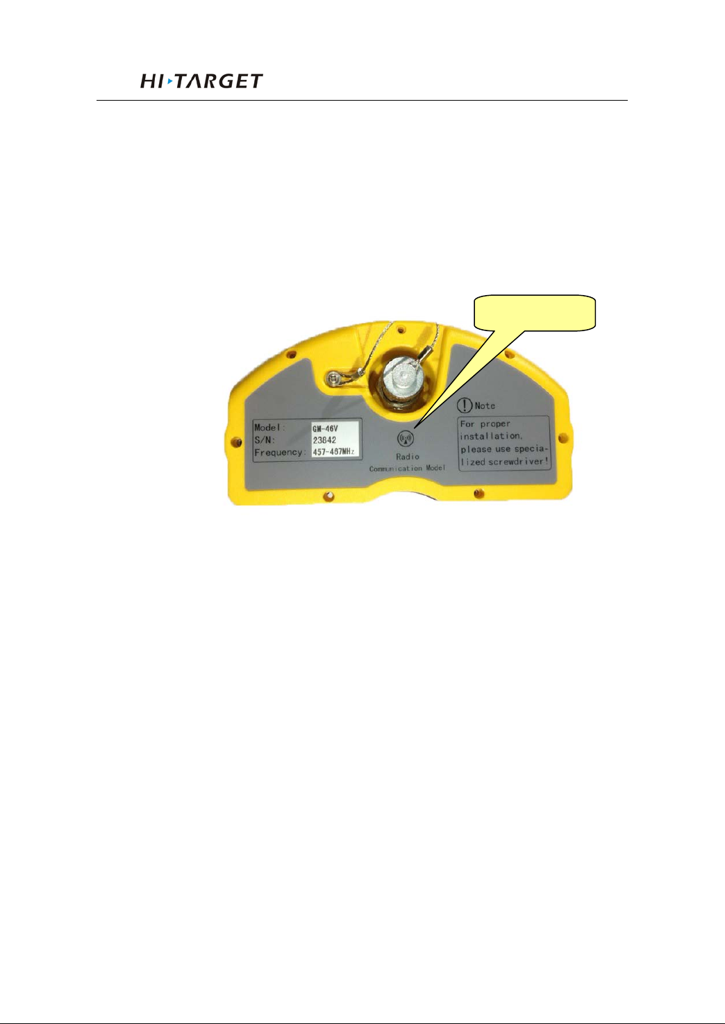
Radio module
Install and Uninstall Communication Modules
Communication modules are radi o module, and GPRS/3G
module.
Figure 4-12 Radio module
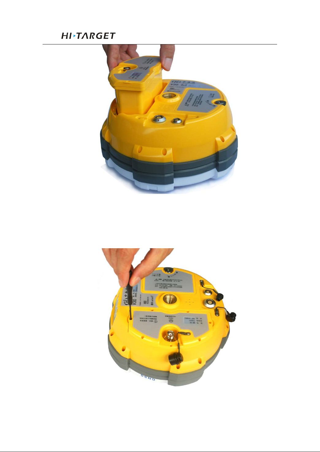
Installation:
1. Put the module into the module s l ot.
37
Page 42
General Operations
Figure 4-14
2. There are 7 s crews in the mod ule. Please screw t hem down
using the screw driver.
38
Figure 4-15
Page 43

V30 GNSS RTK System Manual
Uninstall:
Screw out the 7 scr ews and pull the module out.
Radio Channel Setting
For the GM-46Vradio of 455~465MHz or 440~450MHz,
which is co mpatible w ith V9 , there ar e 100 channels for users’
choice; for the GM-46PV radio of 430 ~ 470MHz and
GM-42PV radio of 390MHz~430MHz, which are compatible
with Trimble Leica, there are 32 channels for users’ choice.
There are two methods to set the radio frequency:
1. Long press F2 on the V30 ma i nf rame to set.
2. After connected with controller, using Hi-RTK software
to set.
Note:
1. The channel of rover must be the same as that of
base, only in which case they can cooperate together.
2. Try to use the channel in a good environment with
less interf erence. The b elow way is o ffered for us ers to find
a good channel:
- Firstly don’t set base, just set the rover in one
channel
- Check the data led (the middle led) of the rover. If
the red led flashes, it hints that there are some other
transmitting data around in this channel. You should
change to ano ther channel unt il you find a channel with
no interference.
- After yo u find a good chann el, setting you r base
39
Page 44
General Operations
GSM
GPRS(ZHD /VRS)
to this channel and start your wor k.
SIM Card/ USIM Card
Either SIM card or USIM card can be used in V30:
WCDMA(ZHD/VRS)
USIM Card
SIM Card
GPRS(ZHD /VRS)
GSM
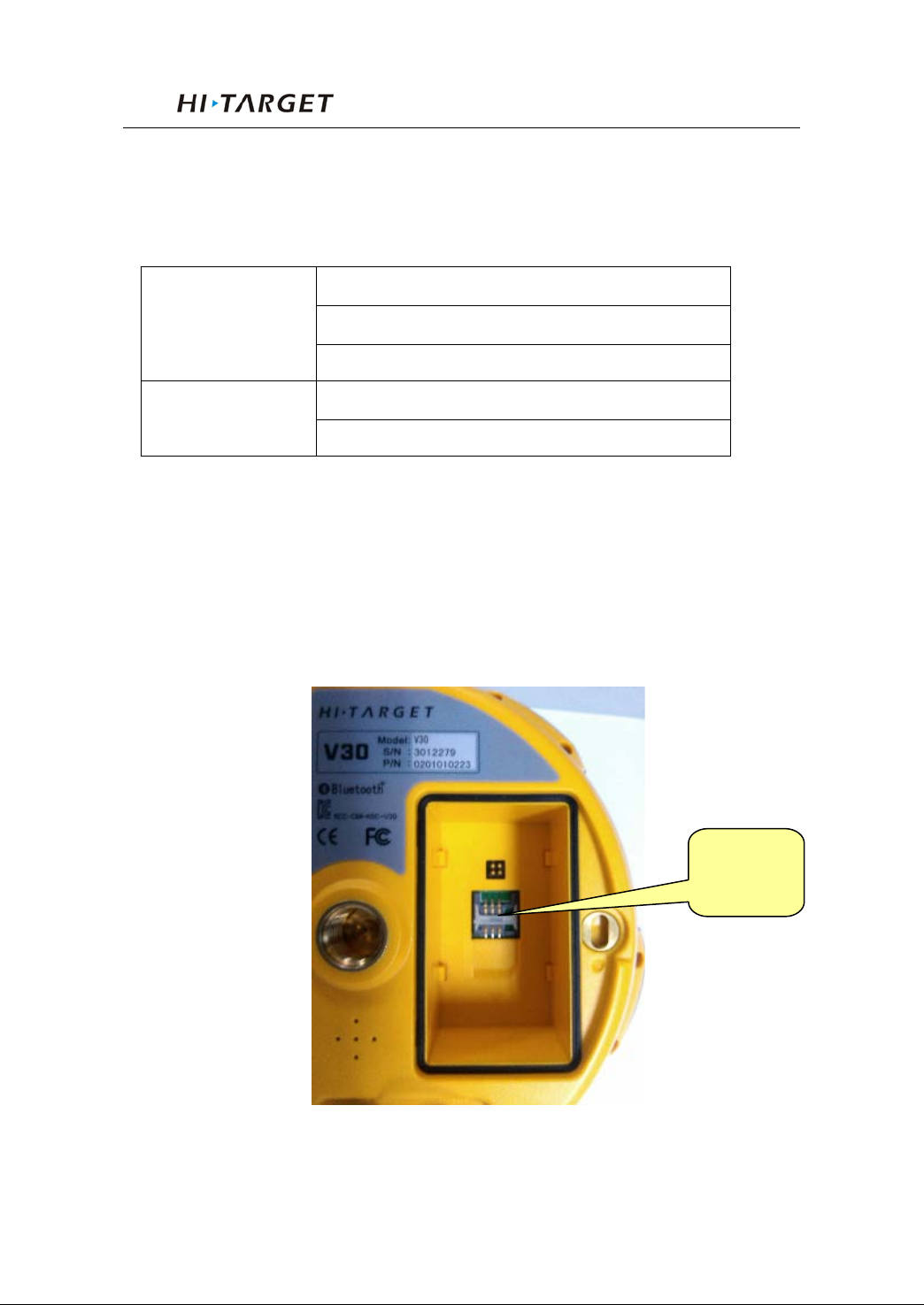
Card installation
For built-in GPRS SIM card:
1. Take out the battery, then you can see the SIM card slot
SIM card
slot
Figure 4-16
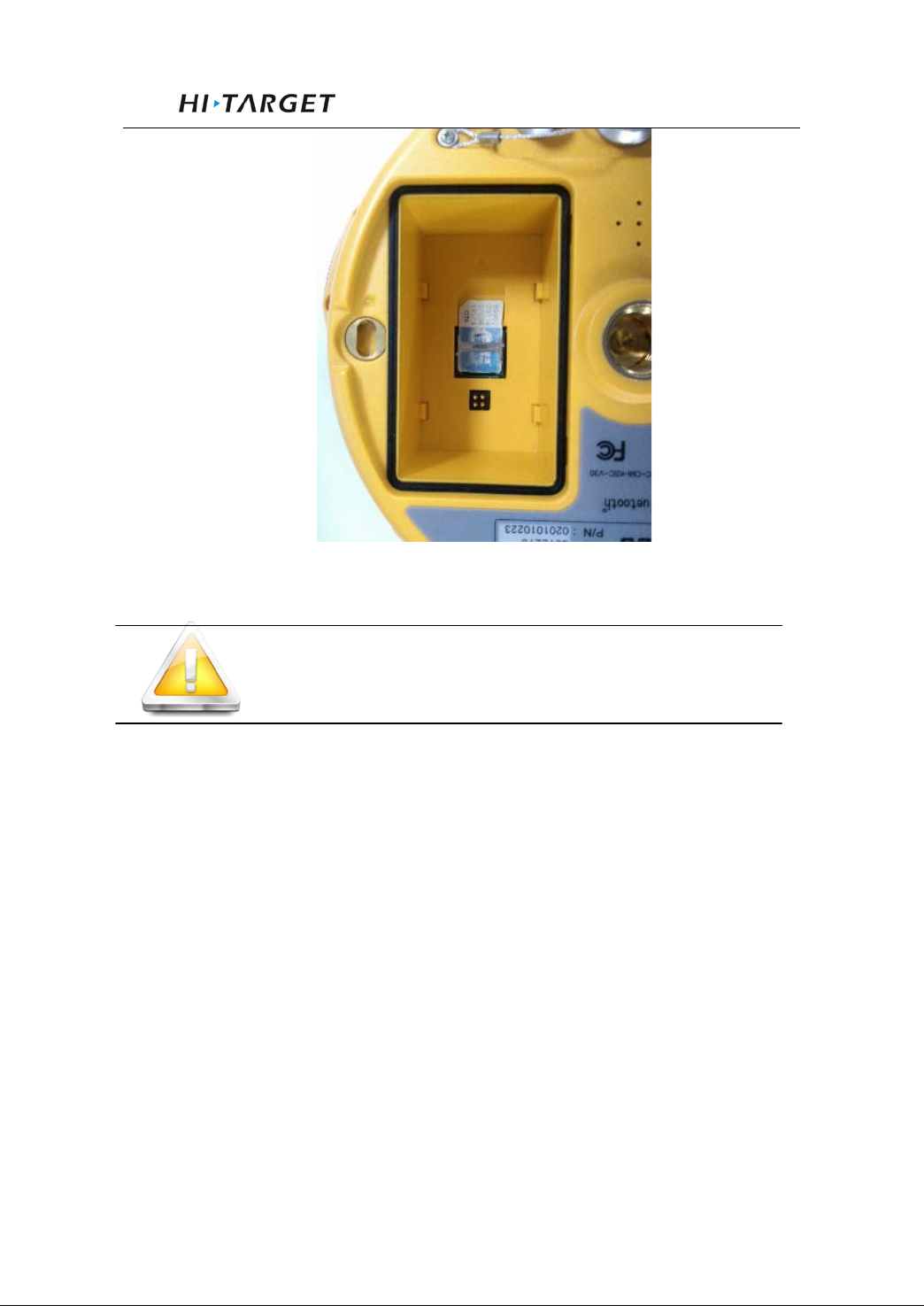
2. Insert SIM card as below:
40
Page 45
V30 GNSS RTK System Manual
Figure 4-17
Note: 3G card can also be installed here.
Firmware
Firmware upgrading
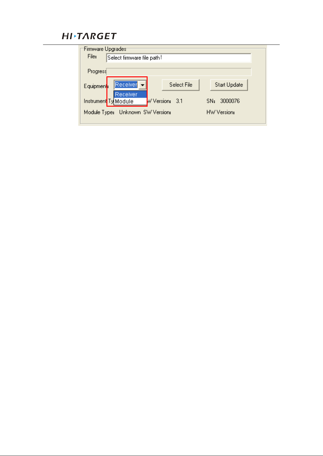
There are two kinds of upgrading for V30: 1. Mainframe
upgrading. 2. Radio module upgrading. Except the difference
of choosing up grading device, all the other operations are the
same. You can see the difference below:
41
Page 46
General Operations
Figure 4-18
Steps for upgrading:
1. Connect V30 with PC by serial port of Y type data
cable
2. Turn on V30 receiver
3. Choose the right serial port and open port
4. After connecting successfully as figure 4-2: the S/N
will be shown in the bottom
5. Choose the “upgrade device” to be “receiver” or
“module” as you need, and then click “select file” to find the
firmware file in you PC
42
Page 47
V30 GNSS RTK System Manual
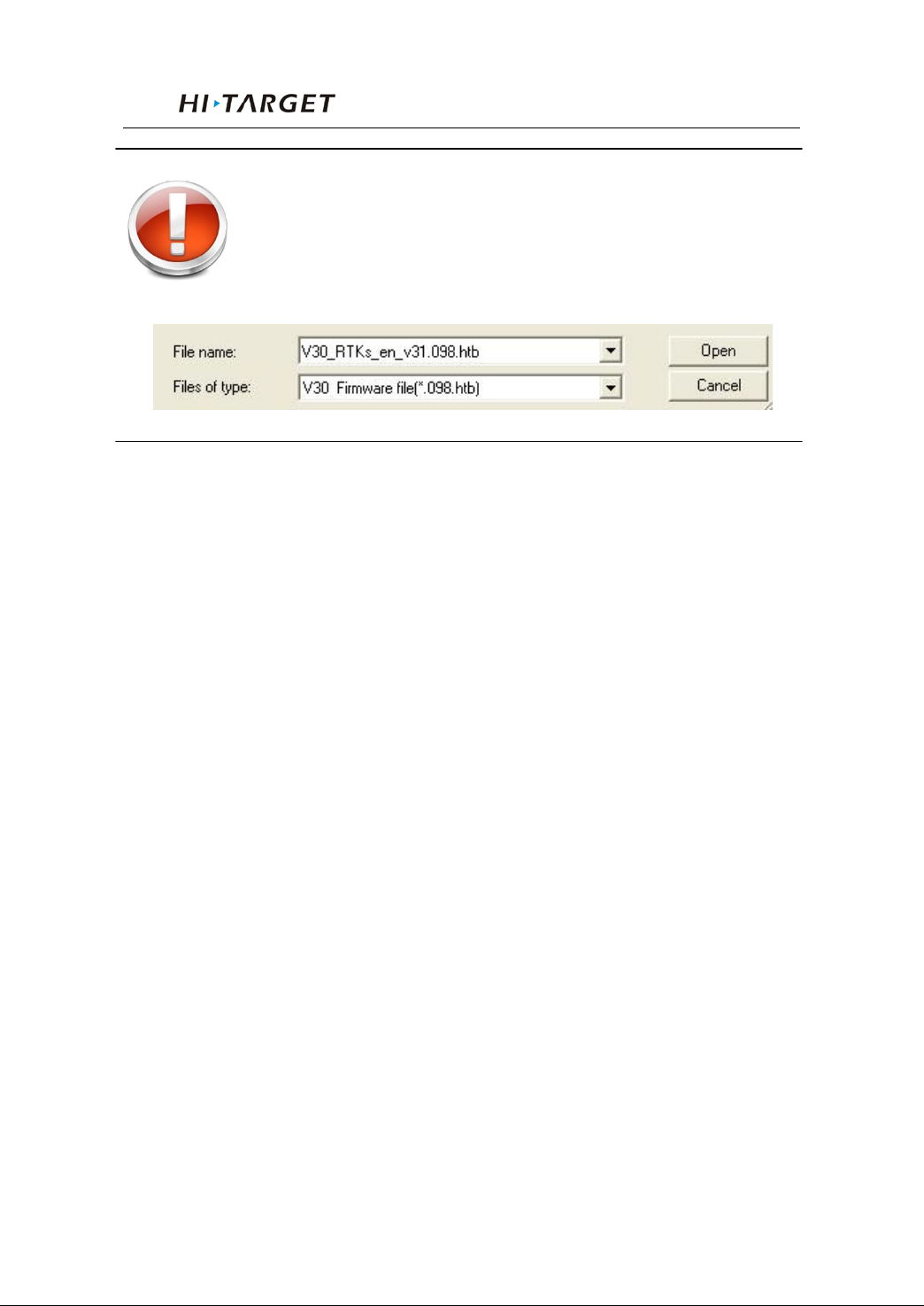
Warning: The firmware file must be with the
postfix as *.098.htb, or the upgrading
will be failed.
6. Click “upgrade” and then the receiver will be turned
off automatically, then sta rt again and it will start upgrading.
7. You c an see the three leds on the panel wi l l fl ash in
turn while upgra ding.
8. When t he software pop up information of upgrading
successfully, then restart your receiver.
43
Page 48

Configuration of Fieldwork
5
C H A P T E R
Configuration of Fieldwork
Chapter Introduction
■ Introduction
■ Diagram for base working
■ Diagram for rover working
■ Fast Operation Guide
44
Page 49
V30 GNSS RTK System Manual
Introduction
In this section, the working program and Easy of Use for
the base and rover of V30 GNSS RTK are introduced.
According to the system of V30 GNSS RTK which is required
by the customer, only the customer who buys the module can
get the relative configuration of working program and the
configuration of working program. The below is not for all the
customers who buy the system of V30 GNSS RTK. Please
refer to the relative configuration of working program for the
instrument whi ch you buy.
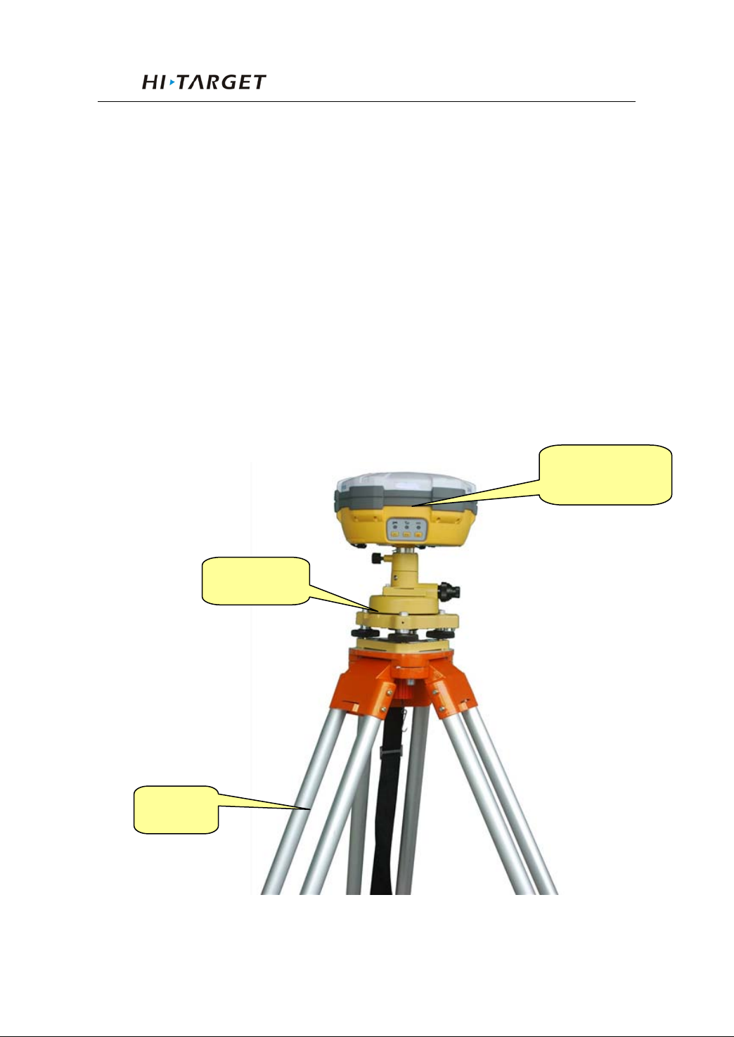
Diagram for base working
Base Mainframe
Tripod
Tribrach
Figure5-1 working mode for base with built-in GPRS/3G
45
Page 50
UHF transmitting
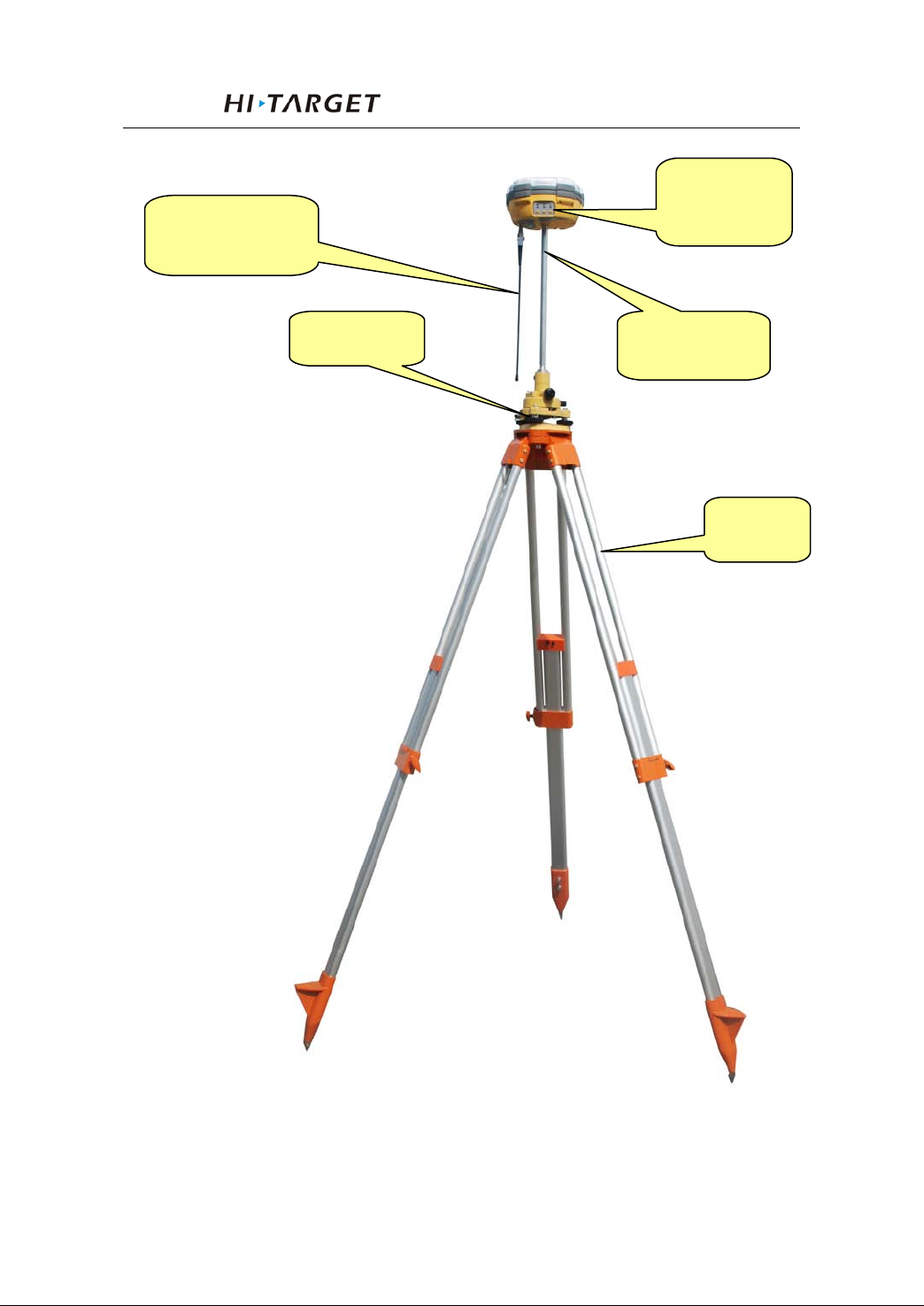
antenna
Configuration of Fieldwork
Base receiver
mainframe
Tribrach
Extension rod
Tripod
46
Figure 5-2 working mode for base with built-in radio
Page 51
V30 GNSS RTK System Manual
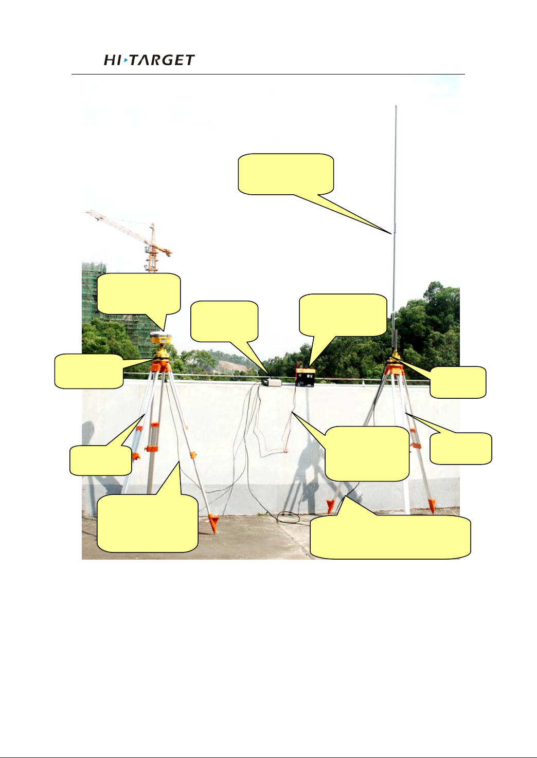
Base receiver
External radio
connecting cable
radio
supply
cable
antenna
Radio antenna connecting
Transmitting
Tribrach
Tripod
mainframe
with receiver
External
External power
Power supply
connecting
cable
Figure 5-3 working mode for base with external radio
Tribach
Tripod
47
Page 52
Configuration of Fieldwork
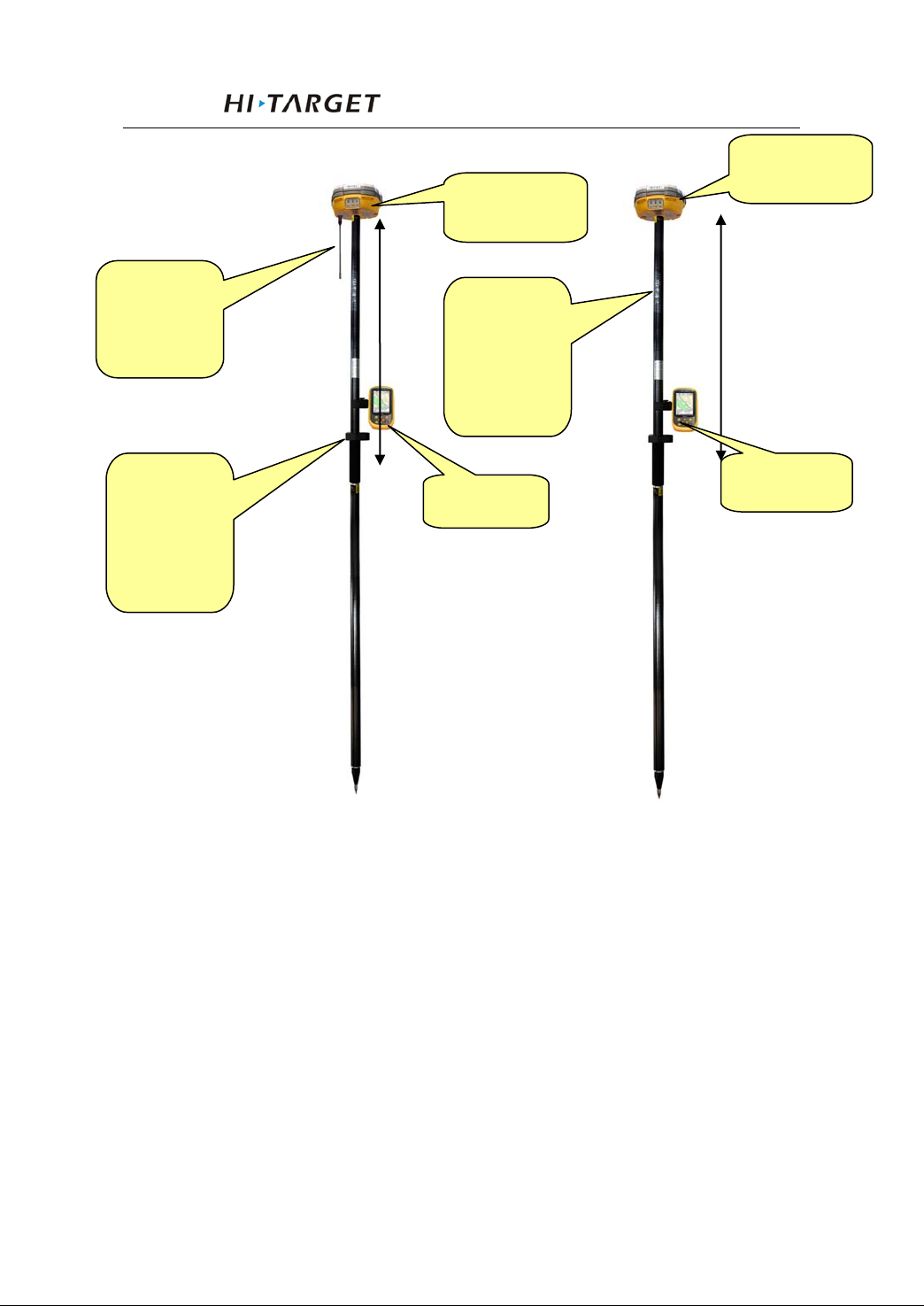
Bluetooth
Rover receiver
Bluetooth
Rover receiver
Diagram for rover working
mainframe
UHF
receiving
antenna
Carbon
fiber
centering
pole
mainframe
Carbon
fiber
centering
pole
Controller
Controller
Figure 5-4 UHF rover Figure5-5 GPRS/3G rover
48
Page 53

V30 GNSS RTK System Manual
Fast Operation Guide
Rover or base mode with built-in GPRS or 3G module.
1. Set base/rover
Double click F1 with the voice prompt “base”, “rover”
and “ static” to choose the working mode you need, press
power button to confirm the setting.
2. Set GSM data l i nk
Double click F2, then choose GSM mode from
UHF,GSM and external radio then click the power button to
confirm.
3. GPRS setting
There are two ways. One is using the Controller with
Hi-RTK software, p lease ref er to Hi -RTK manual to find more
details on how to do the settings. The other way is by using the
management software. Connecting the receiver to PC with Y
type cable, then open the management software of V30
receiver, choose the serial port and then open it. After the
instrument is connected, do the settings through the
management software of V30 receiver. Refer to figure 5-6.
49
Page 54
Configuration of Fieldwork
The dialing function, input the phone
cards have opened the calling function
IP address, port, network operator
(APN), VRS user name, pass word,
Figure 5-6 GPRS Setting
Netw
ork mode
ZHD GPRS/CDM
VRS CDMA/CD
Communicat
ing way
A
GSM
MA
Setting Contents
Group ID, IP, port and APN
number of base. Make sure that the SIM
mount point list
Notes: If the server does not provide IP, you can tick “use
server website ” and then input the website to log in.
Base or rover m ode with UHF radio module
1. Set base/rover
50
Page 55
V30 GNSS RTK System Manual
Double click F1 with the voice prompt “base”, “rover”
and “ static” to choose the working mode you need, press
power button to confirm the setting.
2. Set UHF data link
Double click F2, then choose UHF mode from UHF,GSM
and external ra dio then click the power button to confirm.
3. Set UHF radio channel
Hold F2 button with voice prompt to choose the channel
in need, press power button to con f i rm.
Note: Base and rover must be in the same
channel for a nor mal work.
The differential signal is being transmitted while the
signal light (red) is flashing once at one second. Meanwhile,
the rover have received the signal while the signal light (red)
of rover is flashing synchronously once at one second. Now
RTK work can be started. If the signal led (red ) of rover does
not flash, that means it has not received the differential signal.
4. Set the power of radio:
When the wor king distance beco mes farth er, you can set
the power of the radio of the base through the control panel.
Pressing F1 button until hearing the voice prompt: high,
medium, low, the working distance is getting lower in
51
Page 56

Configuration of Fieldwork
sequence.
Base or rover mode with external data link.
1. Set base/rover:
Double click F1 with the voice prompt “base”, “rover”
and “ static” to choose the working mode you need, press
power button to confirm the setting.
2. Set External data link:
Double click F2, then choose External radio from
UHF,GSM and external radio then click the power button to
confirm.
3. Setting the radio channel of external data link in base.
Do this through adjusting the external UHF radio to the
right channel.
4. Setting the UHF radio channel of rover:
Hold F2 button with voice prompt to choose the channel
in need and press power button to co nf irm.
52
Page 57

V30 GNSS RTK System Manual
6
Static Collecting
Chapter Introduction
■ Introduction
■ The procedure of V30 static survey
C H A P T E R
■ Download data with USB
■ Management software operation for Static Survey
53
Page 58
Static Collecting
Instruction
V30 receiver can be used as dual-frequency static
surveying in strument. Th e collected static su rvey data is saved
in the memory i n the main frame. The static survey data h ave
to be downloaded to PC with post-processing software to
process.
The procedure of V30 static survey
1. Locate the instrument on a point, centering and leveling it.
2. Measure the height of instrument for three times, on
condition that the difference of each measuring is less than
3mm and the final height of the instrument should be the
average height. The height of instrument should be defined
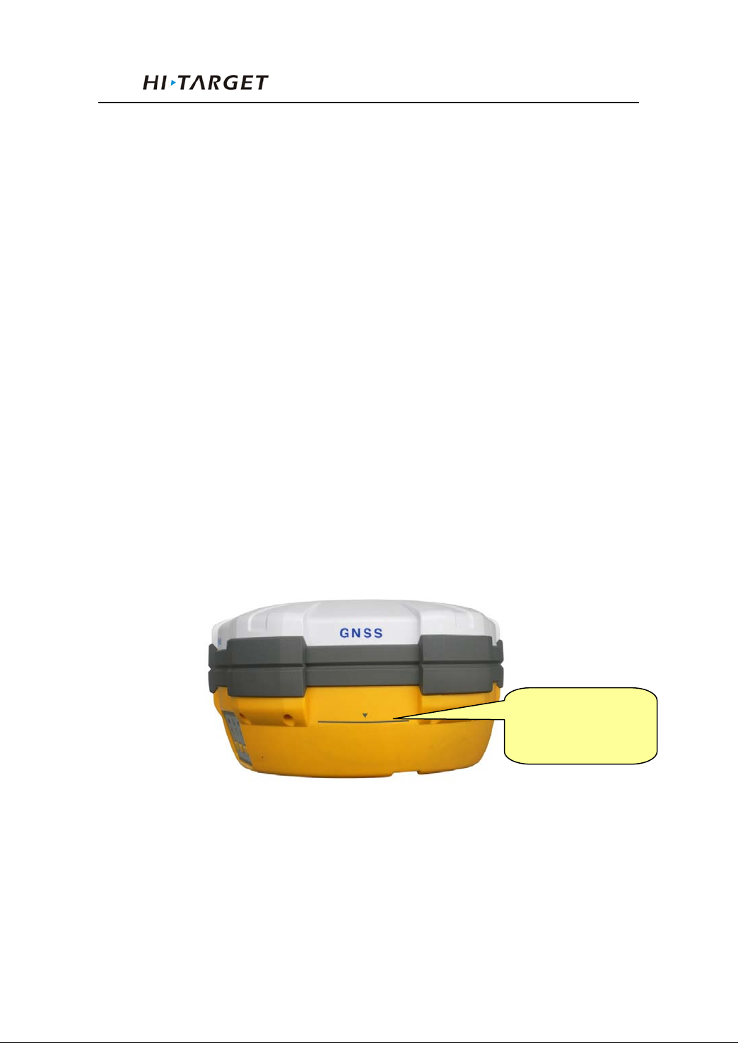
from the controlling point of base centre to upper edge of
marker line. The antenna radius of V30 receiver is 0.087 meter;
the height of phase center is 0.065 meter.
Instrument height
measure point
Figure 6-1 Instrument height measure point
3. Record the point name, instrument S/N, instrument height
and observing i ni tiated time.
54
Page 59
V30 GNSS RTK System Manual
4. Turn on the instrument and set it to static surveying mode.
The satellite led flashing means the instrument is tracking the
satellites. The satellites are locked once the satellite led turns
into constant on. Status led flashes due to your collection
interval. If setting the interval to 1 second the led will flash
once a second.
5. Turn off the instrument after the s t at i c s u rvey is fini sh ed and
record the turn-off time.
Download and post-process the data
Note: Don’t move or change the collecting
setting while the instrument is
collecting data.
Download data with USB drive
The data of V30 receiver can be downloaded with USB
drive, use th e Y type data cable, connect o ne side to USB po rt
of PC and the other side to the 8-pin jack of main frame. Af ter
connecting, you will see a folder named GNSS in the PC, the
static data are here, you can copy t he according files directly.
Note: The series port can not be used to download
data, but can delete static data.
Management software operation for static survey
55
Page 60
Static Collecting
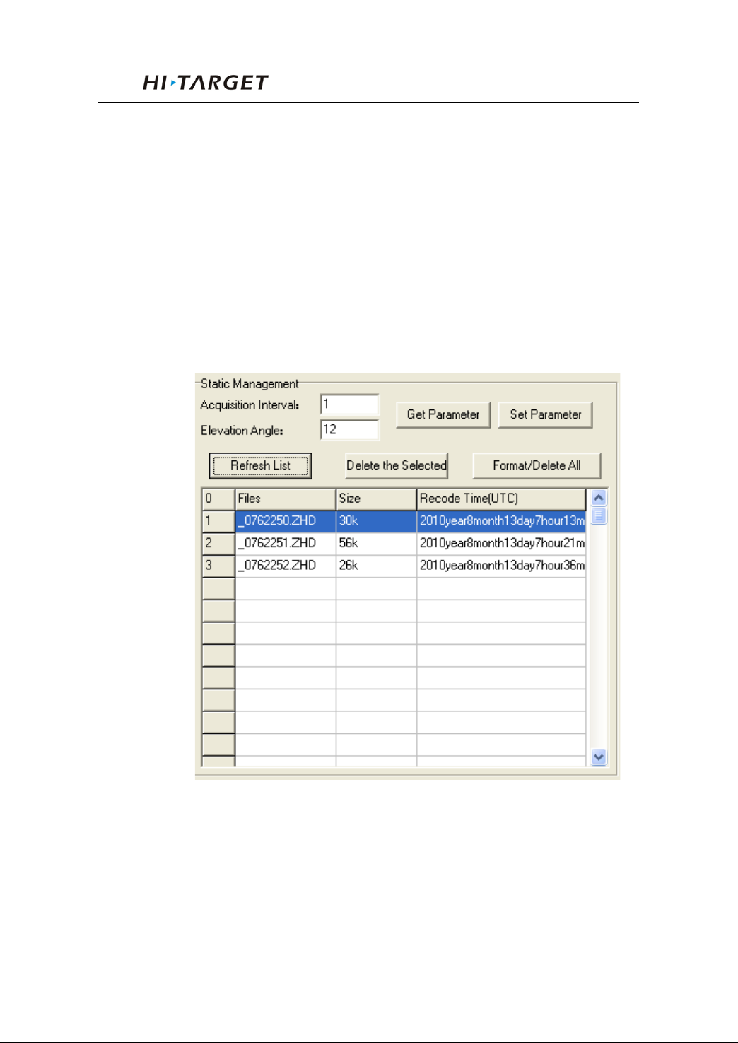
The main function of static file management software
of V30 receiver:
Delete original data
Delete and format the whole mem or y
Read parameters
Set parameters
Refresh list
Figure 6-2
Operating steps:
1. Connect Y type data cable to 8-pin port of V30 recei ver and
the series port of PC
56
Page 61

V30 GNSS RTK System Manual
2. Choose the right PC port and click “connect port”
3. Refresh list, the observation data files will be in the list
4. File name: 8 digit character: the first chart is replaced by
underline, the second, third, and forth are the last two numbers
of S/N number of the receiver from whi ch the data is collected;
the fifth, sixth, and seventh is the year-accumulated-date; the
last chard is the collecting period of the day
5. Set up time: GNSS time.
6. Delete dat a: choose th e data need to be deleted , click del ete
files.
7. Change collecting interval and satellite cutoff/elevation
angle: input value and click set parameters. Click read
parameters to view th e origin al collectin g interval and satellite
cutoff angl e.
Static data post processing:
The new post processing software of Hi-Target is
Hi-Target Geomatics Office (HGO), use this software to do
post processing.
Please refer to “Hi-Target Geomatics Office Data Post
Processing Software Man ual” for detailed i nformation of data
processing.
57
Page 62

Technical Parameters
7
Technical Parameters
Chapter Introduction
■ Introduction
■ Receiver
C H A P T E R
■ UHF Radio Communication
■ 3G/GPRS/CDMA/Internet Communication
■ Ports
■ Function Key and Indicator Led
■ Intelligent Voice Module
■ Accuracy
■ Physical Feature
■ Working Environment
58
Page 63

V30 GNSS RTK System Manual
Introduction
Here we list out all Technical Parameters of V30 GNSS
RTK SYSTEM. The Technical Parameters will be a little
different according to your purchase order. Please make sure
about your configuration then find out Technical Parameters
correspondingly.
Receiver
◎ 220 channels
◎ GPS : Synchronous tracking L1 C / A, L2E, L2C, L5
◎ GLONASS: Synchronous tracking L1 C/A , L1 P, L2
C/A(only for GLONASS M) and L2P
◎ SBAS: Synchronous tracking L1 C/A, L5
◎ GIOVE-A:synchronous t racking L1 BOC, E5A, E5B and
E5AltBOC(optional)
◎ GIOVE-B : synchronous L1 CBOC, E5A, E5B and
E5AltBOC(optional)
◎ GALILEO:( Upgrade)
◎ Tri m bl e M axwell 6 of adv anced user-defined GNSS
Technology
◎ A high precision measurement in the relevant organs using
for global navigation satellite system
◎ Very low noise GNS S car ri er p has e in Su rveyi ng , Accu r acy
< 1 mm within 1 HZ wide band
◎ M ature l ow el evati on-angle tracking technology
◎ Initialization time < 10 S
◎ Initialization Reliability > 99.9%
◎ 1 Hz, 2 Hz, 5 Hz, 10 Hz, 20Hz and 50 Hz output (default
59
Page 64

Technical Parameters
10Hz)
◎ Differential data format: CM R, CM R+, RTCM 2.1, 2.2,
2.3, 3.0, 3.1
◎ N avigati on O utput Form at: A SCII :NMEA-0183 GSV,
AVR, RMC, HDT, VGK, VHD, ROT, GGK, GGA,
GSA, ZDA, VTG, GSTPJT, PJK, BPQ, GLL, GRS, GBS
and binary sys t em:Trimble GSOF
UHF Radio Communication
GM-46V Module
◎ Compatible with V8 and the other products of Hi-Target
with transmi t t i ng or receiving radio in 460 MHz
◎ W i th difference transmi t-receiver function and transmit
power can be adjustable among 0.1w, 1w and 2w
◎ Radio Frequency bands of 450 ~470MHz with 100 flexible
switching channels
◎ Reference to Radi o Frequency l i st
◎ W ith top 19.2 K bps w i rel ess transm i t speed
PCC Radio Module
◎ Compatible with Trimble/Leica RTK Radio
◎ W i th di fference transmi t-receiver function and transmit
power can be adjustable to be 0.1 w, 0.5w or 1 w
◎ Radio Frequency bands 430 M Hz ~ 470MHz with 32
flexible switching channels and the frequency of each
channel can be customized.
◎ W ith top 19.2 K bps w i rel ess transm i t speed
◎ Support the below protocol, convenient for user to work
compatible with their own products:
60
Page 65

V30 GNSS RTK System Manual
o T rans pare nt EOT Time out
o Transparent EOC Character
o Packet Switched
o TRIMTALK 450S
o TRIMMARK II/IIe
o TRIMTALK 3
o TT450S
o SATEL
External PCC Radio
◎ Original import PCC radio
◎ Input power: DC 9~30 V
◎ Transm i t-receiver radio. The top transmit power has
differe nt optional as 4W or 35 W
◎ Radio Frequency bands 430 M Hz ~ 470MHz with 32
flexible switching channels and the baud rate of each
channel can be customized.
◎ W ith top 19.2 Kbps wireless transmit speed
◎ Support the below protocol, convenient for user to work
compatible with their own products:
o Tra nspa rent EOT Timeout
o Transparent EOC Character
o Packet Switched
o TRIMTALK 450S
o TRIMMARK II/IIe
61
Page 66

Technical Parameters
o TRIMTALK 3
o TT450S
o SATEL
3G/GPRS Network Communication
◎ Default Configuration with built in GPRS Internet
Communica t i on, with optional of 3G Module.
Ports
◎ 2 RS-232 serial ports
◎ 1 USB port
◎ 1 port for wireless blue-tooth communication
◎ 2 port for external D C pow er suppl y ( M ul ti pl ex)
◎ 1 SIM card slot for GSM or CDM A
◎ 1 built-in Li-ion battery groove
◎ 1 built-in communica t i on module port
Function Key and LED
◎ 3 Panel buttons: 1 power switch key, 2 functional keys,
with these combination you can set all the function with
voice and Indic ator Led flexibility
◎ 3 LEDs: 1 Satellite LED (Single color), 1 Communication
LED ( Dual Color) ,1 Power LED ( D ual Color)
Intelligent Voice Module
◎ Broadcasting function for each operation in E nglish
Accuracy
◎ Stati c, F ast Stati c: H ori zontal : ±(2. 5 +1×10⁻⁶D) mm
Vertical: ±(5+1×10⁻⁶D) mm
62
Page 67

V30 GNSS RTK System Manual
◎ RTK Accuracy: Horizontal: ±(10+1×10⁻⁶D) mm
Vertical: ±(20+1×10⁻⁶D) mm
Physical Feature
◎ W ith ARM 7 Core Control Chip, built-in 64 M Flash
Memory
◎ Dimension: φ19.5cm×h10.4cm
◎ Weight: 1.3 kg( Incl. li-ion battery)
◎ A nti -impact from 3 meters free-falling, waterproof in 2
meters deep water
◎ Lithium battery. W ith 2 standard battery in 4400 mAh ,
Voltage:7.4 V; One Single battery can work continuously
for 13 hours in static mode, 12 hours in GPRS mode, and 8
hours in 2 W transmitt ing power
◎ 6~36V external DC power supported, external and internal
power supply exchanged automatic
◎ Recei v er Pow er Consumpti on: 2. 5W
Environment
◎ IP Standard: IP67, waterproof, dust-proof and anti-impact.
◎ W ork i ng tem perature: -45℃~65℃, storage temperature:
-55℃~85℃
◎ 100% Humidity non-condensing
63
Page 68

Ports and Main Accessory
8
Ports and Main Accessory
Chapter Introduction
■ Introduction
■ 5-pin Port and 8-pin Port
C H A P T E R
■ Differential Antenna
■ Y Style Data Cable
64
Page 69
V30 GNSS RTK System Manual
Introduction
This Section will introduce the out look and operation for
the main ports and accessory of V30 GNSS RTK system. The
Technical Parameters will be a little different according to your
purchase order. Please make sure about your configuration
then find out Technical Parameters correspondingly.
Five-pin Port and Eight-pin Port
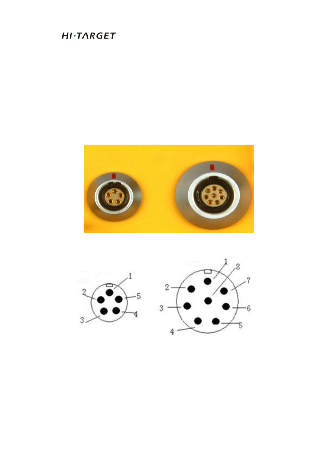
Figure 8-1 Five-pin Port and Eight-pin Port
Figure 8-2 Five-pin Port Eight-pin Port
1. Five-pin port: named as COM2/PW2, Generally used for
the connection between the receiver mainframe and the
external data link or the external power supply
65
Page 70
Ports and Main Accessory
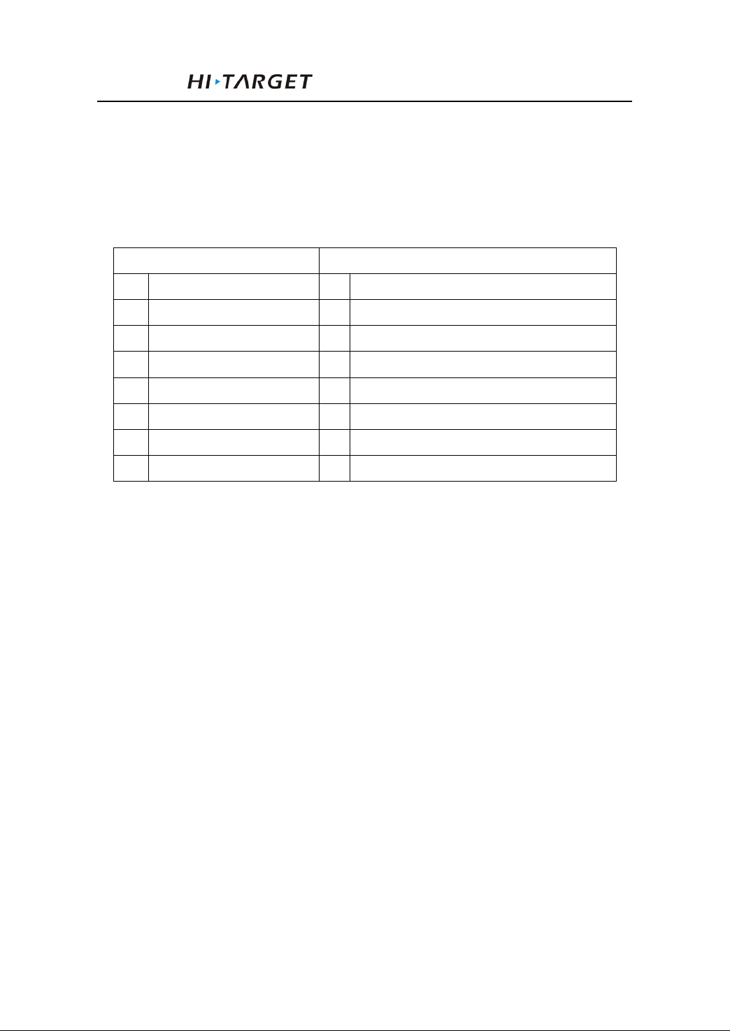
GND Earth
RXD Data Input
GND Earth USB D-
Vin Power Input
USB D+
RXD Data Input
USB V+
GC-2 Cable Insert Mark
TXD Data Output
GND Earth
Eight-pin port: Named as COM 1/USB/PW1, Generally
used for the connection between the receiver mainframe
and computer, controller, or for data download and data
delete.
Signal Definition
Small Five -pin Signal larger Eight-pin Signal
TXD Data Output
Vin Power Input
2. Cable Insert Mark GC-1, GC-2 signal can work with the
cable connect earth internal only.
3. All the round plug seats from Hi-Target name the pin by
positive counterclockwise; round plug name the pin by
welding face counterclockwise.
4. All above data output (TXD) and input( RXD) signal are
base on receiver. TXD is a signal transmit line for r eceiver
and RXD is receive line for receiver.
5. The connect signal for PC serial port DB9 are: 2 (RXD
computer data signal to receive),3( TXD computer data
signal to transmit),5(GND earth). In a simple word “2 for
receiver 3 for transmit”
66
Page 71
V30 GNSS RTK System Manual
Point: All above are for facing the main frame,
it’s the face icon for the socket of bottom
main frame ( The plug welding surface)
Differenti al Ant enna
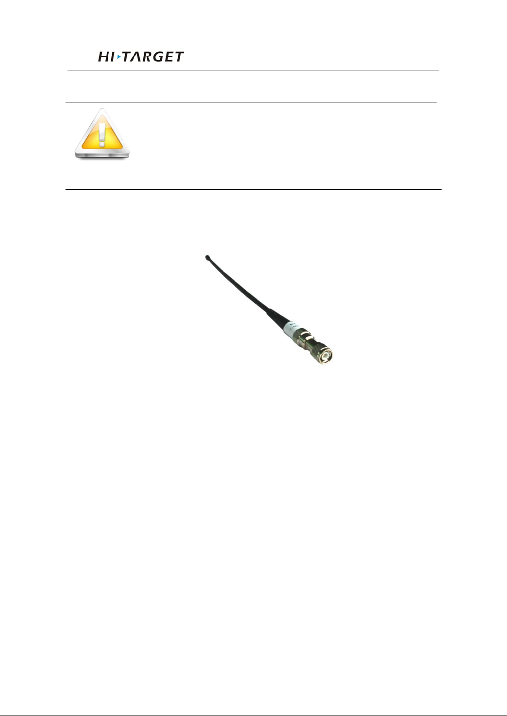
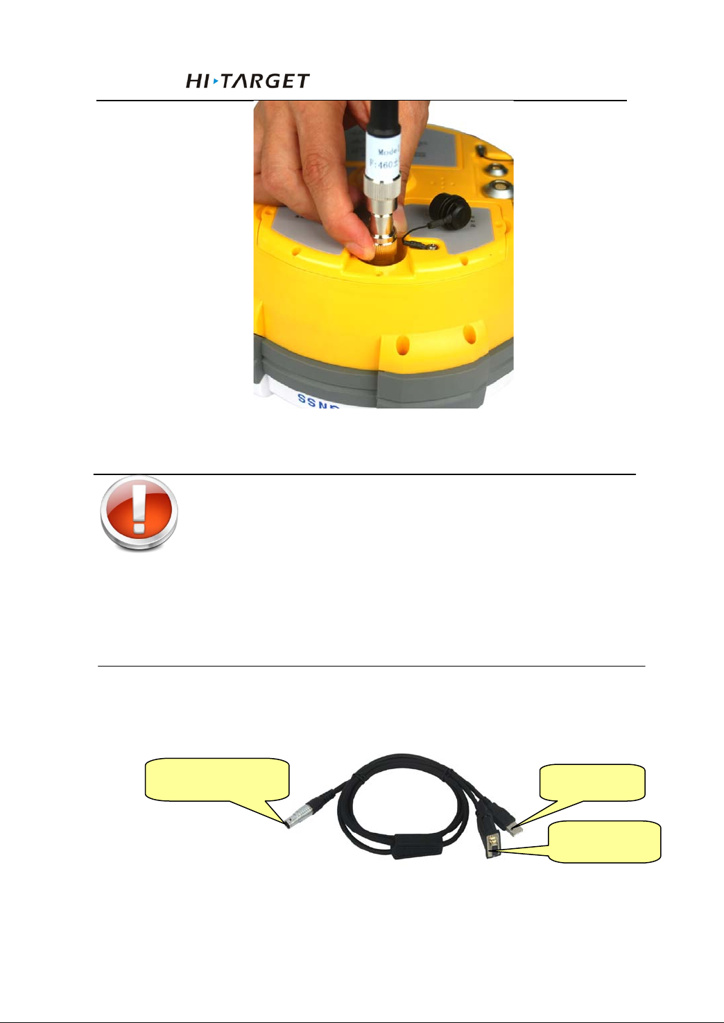
Figure 8-3 Differential Antenna
Refer to Figure 8-3, the di fferen t i al an t enna is an essential
part both to Base and Rover with internal UHF radio, which
transmits the UHF differential signal for Base while receiving
the UHF differential signal for Rover.
Differential Antenna Installation
Refer to Figure 8-4,holding the bottom of differential
antenna and assemble it with clockwise rotation. On the
contrary you can disassemble the differential antenna.
67
Page 72
Ports and Main Accessory
USB Port
Figure 8-4 Differential Antenna installation
Warning: When install the differential antenna,
make sure rotating the right bottom fixed
nut of differential antenna, don’t grip the
top parts of differ ential an tenna, Otherwi se,
it will make poor connect and reduce the
working distance .
Y Type Data Cable
Eight-pin Port
Figure 8-5 Y Type Data Cable
Serial Port
68
Page 73
V30 GNSS RTK System Manual
Eight-pin Port: to connect with the eight-pin port of V30
receiver
USB Port: to connect with PC USB for data downloading
from V30
Serial Port: to connect with PC serial port for V30
firmware upg r ad e, r ecei v er settings, ma n ag e static data fi l e,
set radio parameters, etc.
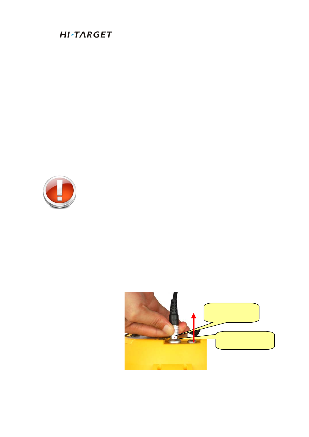
Warning: 1. When connecting plugs of all the
V30 GNSS RTK system,( See below) please
make sure to make two red points aligned , one
on plug and the other in the V30 receiver so cket,
otherwise, it will bring damage both to socket
and plug.
2. When finis h you r wo rk , pleas e tak e ou t of plug
directly. Don’t spin the plug.
3. In order to protect the plug, please store the
cable in a good status and places without
extruding.
Plug red dot
Socket red dot
69
Page 74

Regulatory Information
9
Regulatory Information
Chapter Introduction
■ Notes
C H A P T E R
70
Page 75

V30 GNSS RTK System Manual
Notes
Warning: Changes or modifications to this unit not expressly
approved by the party responsible for compliance could void
the user’s authority to operate t he equipment.
NOTE: This equipment has been tested and found to comply
with the limit s for a Clas s B dig ital devi ce, purs uant to Part 15
of the FCC Rules. These limits are designed to provide
reasonable protection against harmful interference in a
residential installation. This equipment generates, uses and can
radiate radi o frequ ency energy and , if no t inst alled and used in
accordance with the instructions, may cause harmful
interference to radio comm uni cations.
However, there is no guarantee that interference will not occur
in a particular installation. If this equipment does cause
harmful interference to radio or television reception, which can
be determined by turning the equipment off and on, the user is
encouraged to try to correct the interference by one or more of
the following measures:
1. Reorient or relocate the receiving antenna.
2. Increase the separation between the equipment and receiver.
3. Connect the equipment into an outlet on a circuit different
from that to which the receiver is connected.
4. Consult the dealer or an experienced radio/TV technician for
help.
Shielded cables must be used with this unit to ensure
compliance with the Class B FC C limits.
71
 Loading...