

Page 1
Page 2

Page 3

INTRODUCTION
TO THE READER
• This manual is written for an experienced technician
to provide technical information needed to maintain
and repair this machine.
• Be sure to thoroughly read this manual for correct product information and service procedures.
ADDITIONAL REFERENCES
• Please refer to the materials listed below in addition
to this manual.
• The Operator’s Manual
• The Parts Catalog
MANUAL COMPOSITION
• This manual consists of three portions: the Techni-
cal Manual (Operational Principle), the Technical
Manual (Troubleshooting) and the Workshop Manual.
• Information included in the Technical Manual
(Operational Principle):
technical information needed for redelivery and
delivery, operation and activation of all devices
and systems.
PAGE NUMBER
• Each page has a number, located on the center
lower part of the page, and each number contains
the following information:
Example : T
1-3-5
Consecutive Page Number for Each Group
Group Number
Section Number
T: Technical Manual W: Workshop Manual
• If you have any questions or comments, at if you
found any errors regarding the contents of this
manual, please contact using “Service Manual
Revision Request Form” at the end of this manual.
(Note: Do not tear off the form. Copy it for usage.):
Publications Marketing & Product Support
Hitachi Construction Machinery Co. Ltd.
TEL: 81-29-832-7084
FAX: 81-29-831-1162
• The Engine Manual
• Parts Catalog of the Engine
• Hitachi Training Material
• Information included in the Technical Manual
(Troubleshooting):
technical information needed for operational performance tests, and troubleshooting procedures.
• Information included in the Workshop Manual:
technical information needed for maintenance
and repair of the machine, tools and devices
needed for maintenance and repair, maintenance
standards, and removal/installation and assemble/disassemble procedures.
IN-01
Page 4
INTRODUCTION
SAFETY ALERT SYMBOL AND HEADLINE
NOTATIONS
In this manual, the following safety alert symbol and
signal words are used to alert the reader to the
potential for personal injury of machine damage.
This is the safety alert symbol. When you see this
symbol, be alert to the potential for personal injury.
Never fail to follow the safety instructions prescribed
along with the safety alert symbol.
The safety alert symbol is also used to draw attention
to component/part weights.
To avoid injury and damage, be sure to use appropriate lifting techniques and equipment when lifting
heavy parts.
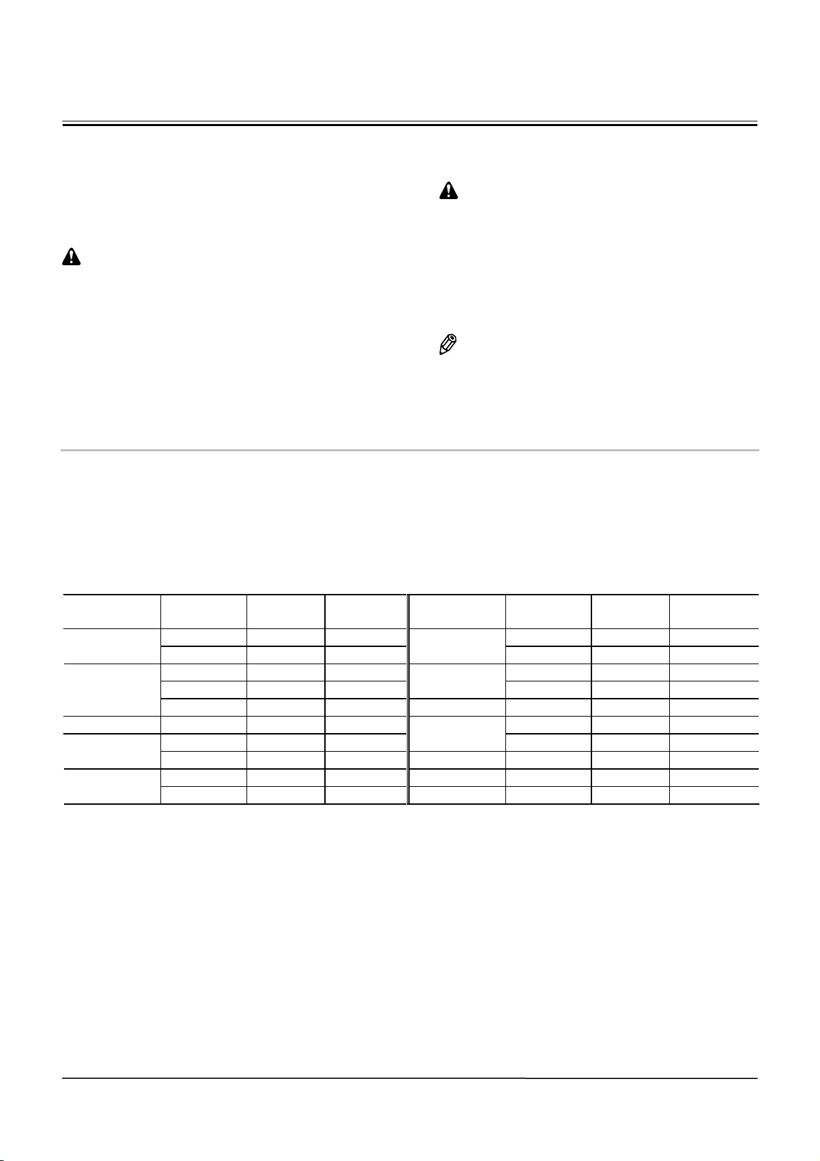
UNITS USED
• SI Units (International System of Units) are used in
this manual.
MKSA system units and English units are also
indicated in parenthheses just behind SI units.
Quantity
Volume
Weight kg lb 2.205
To Convert
From
mm in 0.03937 Length
mm ft 0.003281
L US gal 0.2642
L US qt 1.057
3
m
yd3 1.308
N kgf 0.10197 Force
N lbf 0.2248
N⋅m kgf⋅m 1.0197 Torque
N⋅m lbf⋅ft 0.7375
Into Multiply By
Temperature °C °F °C×1.8+32
Flow rate L/min US gpm 0.2642
mL/rev cc/rev 1.0
• CAUTION:
Indicated potentially hazardous situation which
could, if not avoided, result in personal injury or
death.
• IMPORTANT:
Indicates a situation which, if not conformed to the
instructions, could result in damage to the machine.
• NOTE:
Indicates supplementary technical information or
know-how.
Example : 24.5 MPa (250 kgf/cm2, 3560 psi)
A table for conversion from SI units to other system
units is shown below for reference purposees.
Quantity
To Convert
From
MPa kgf/cm2 10.197 Pressure
MPa psi 145.0
kW PS 1.360 Power
kW HP 1.341
km/h mph 0.6214 Velocity
-1
rpm 1.0
min
Into Multiply By
IN-02
Page 5
SAFETY
RECOGNIZE SAFETY INFORMATION
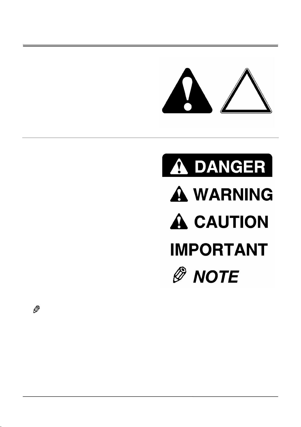
• These are the SAFETY ALERT SYMBOLS.
• When you see these symbols on your machine or
in operator`s manual, be alert to the potential for
personal injury.
• Follow recommended precautions and safe oper-
ating practices.
001-E01A-0001
UNDERSTAND SIGNAL WORDS
• On machine safety signs, signal words designating
the degree or level of hazard - DANGER, WARNING,
or CAUTION - are used with the safety alert symbol.
• DANGER indicates an imminently hazardous
situation which, if not avoided, will result in death
or serious injury.
• WARNIN G indicates a potentially hazardous
situation which, if not avoided, could result in
death or serious injury.
• CAUTION indicates a potentially hazardous
situation
• which, if not avoided, may result in minor or
moderate injury.
• DANGER or WARNING safety signs are located
near specific hazards. General precautions are
listed on CAUTION safety signs.
• Some safety signs don’t use any of the desig-
nated signal words above after the safety alert
symbol are occasionally used on this machine.
• To avoid confusing machine protection with per-
sonal safety messages, a signal word IMPOR-
TANT indicates a situation which, if not avoided,
could result in damage to the machine.
•
NOTE indicates an additional explanation for
an element of information.
002-E01A-1223
SA-688
SA-1223
SA-1
Page 6
SAFETY
FOLLOW SAFETY INSTRUCTIONS
• Carefully read and follow all safety signs on the
machine and all safety messages in operator`s
manual.
• Safety signs should be installed, maintained and
replaced when necessary.
• If a safety sign or operator`s manual is damaged
or missing, order a replacement from your authorized dealer in the same way you order other
replacement parts (be sure to state machine
model and serial number when ordering).
• Learn how to operate the machine and its controls
correctly and safely.
• Allow only trained, qualified, authorized personnel to
operate the machine.
• Keep your machine in proper working condition.
• Unauthorized modifications of the machine may
impair its function and/or safety and affect machine life.
• Do not modify any machine parts without au-
thorization.
Failure to do so may deteriorate the part safety,
function, and/or service life. In addition, personal
accident, machine trouble, and/or damage to
material caused by unauthorized modifications
will void Hitachi Warranty Policy.
• Do not use attachments and/or optional parts or
equipment not authorized by Hitachi. Failure to do
so may deteriorate the safety, function, and/or
service life of the machine. In addition, personal
accident, machine trouble, and/or damage to
material caused by using unauthorized attachments and/or optional parts or equipment will void
Hitachi Warranty Policy.
• The safety messages in this SAFETY chapter are
intended to illustrate basic safety procedures of
machines. However it is impossible for these safety
messages to cover every hazardous situation you
may encounter. If you have any questions, you
should first consult your supervisor and/or your authorized dealer before operating or performing
maintenance work on the machine.
003-E01B-0003
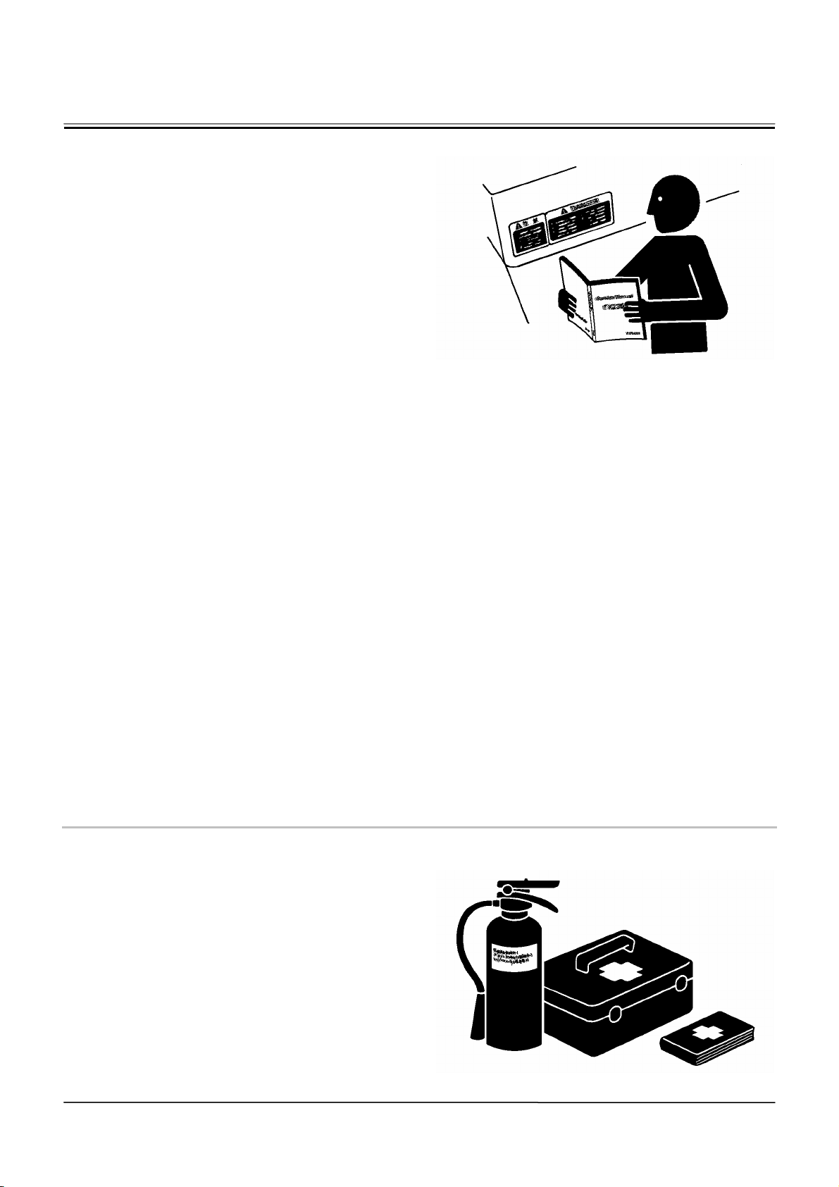
PREPARE FOR EMERGENCIES
• Be prepared if a fire starts or if an accident occurs.
• Keep a first aid kit and fire extinguisher on hand.
• Thoroughly read and understand the label at-
tached on the fire extinguisher to use it properly.
• To ensure that a fire-extinguisher can be always
used when necessary, check and service the
fire-extinguisher at the recommended intervals as
specified in the fire-extinguisher manual.
• Establish emergency procedure guidelines to
cope with fires and accidents.
• Keep emergency numbers for doctors, ambu-
lance service, hospital, and fire department
posted near your telephone.
SA-003
004-E01A-0437
SA-437
SA-2
Page 7
SAFETY
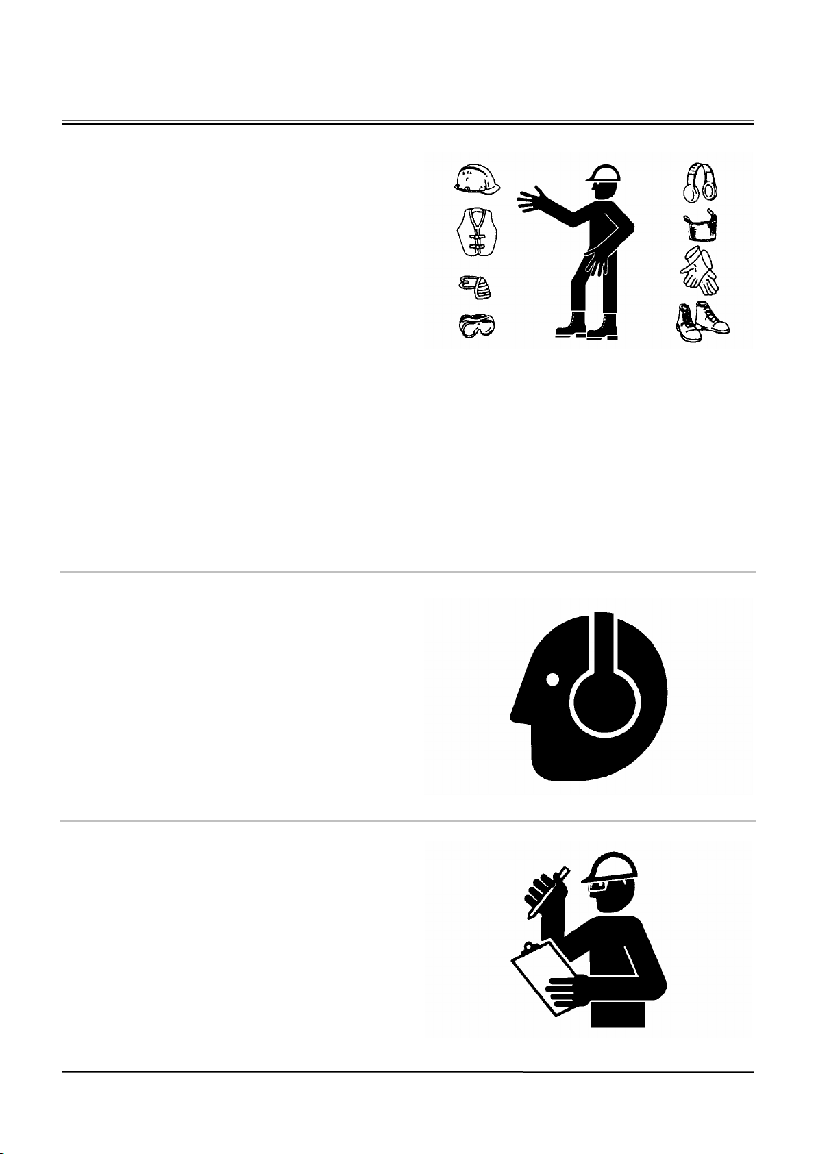
WEAR PROTECTIVE CLOTHING
• Wear close fitting clothing and safety equipment
appropriate to the job.
You may need:
A hard hat
Safety shoes
Safety glasses, goggles, or face shield
Heavy gloves
Hearing protection
Reflective clothing
Wet weather gear
Respirator or filter mask.
Be sure to wear the correct equipment and clothing
for the job. Do not take any chances.
• Avoid wearing loose clothing, jewelry, or other
items that can catch on control levers or other
parts of the machine.
• Operating equipment safely requires the full atten-
tion of the operator. Do not wear radio or music
headphones while operating the machine.
005-E01A-0438
PROTECT AGAINST NOISE
• Prolonged exposure to loud noise can cause im-
pairment or loss of hearing.
• Wear a suitable hearing protective device such as
earmuffs or earplugs to protect against objec-
tionable or uncomfortably loud noises.
006-E01A-0434
NSPECT MACHINE
• Inspect your machine carefully each day or shift by
walking around it before you start it to avoid personal injury.
• In the walk-around inspection be sure to cover all
points described in the “PRE-START INSPEC-
TION” chapter in the operator’s manual.
007-E01A-0435
SA-438
SA-434
SA-435
SA-3
Page 8

GENERAL PRECAUTIONS FOR CAB
• Before entering the cab, thoroughly remove all dirt
and/or oil from the soles of your work boots. If any
controls such as a pedal is operated while with
dirt and/or oil on the soles of the operator’s work
boots the operator’s foot may slip off the pedal,
possibly resulting in a personal accident.
• Do not leave parts and/or tools lying around the
operator’s seat. Store them in their specified lo-
cations.
• Avoid storing transparent bottles in the cab. Do
not attach any transparent type window decora-
tions on the windowpanes as they may focus
sunlight, possibly starting a fire.
• Refrain from listening to the radio, or using music
headphones or mobile telephones in the cab
while operating the machine.
• Keep all flammable objects and/or explosives
away from the machine.
• After using the ashtray, always cover it to extin-
guish the match and/or tobacco.
• Do not leave cigarette lighters in the cab. When
the temperature in the cab increases, the lighter
may explode.
524-E01A-0000
SAFETY
SA-4
Page 9
SAFETY
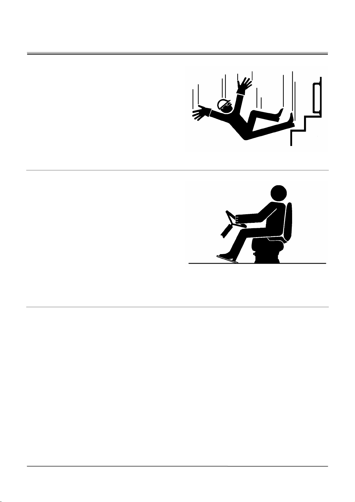
USE HANDHOLDS AND STEPS
• Falling is one of the major causes of personal injury.
• When you get on and off the machine, always
face the machine and maintain a three-point
contact with the steps and handrails.
• Do not use any controls as hand-holds.
• Never jump on or off the machine. Never mount or
dismount a moving machine.
• Be careful of slippery conditions on platforms,
steps, and handrails when leaving the machine.
008-E01A-0439
ADJUST THE OPERATOR'S SEAT
• A poorly adjusted seat for either the operator or for
the work at hand may quickly fatigue the operator
leading to misoperations.
• The seat should be adjusted whenever changing
the operator for the machine.
• The operator should be able to fully depress the
pedals and to correctly operate the control levers
with his back against the seat back.
• If not, move the seat forward or backward, and
check again.
• Adjust the rear view mirror position so that the
best rear visibility is obtained from the operator’s
seat. If the mirror is broken, immediately replace it
with a new one.
009-E01A-0462
ENSURE SAFETY BEFORE RISING FROM
OR LEAVING OPERATOR’S SEAT
• Before rising from the operator’s seat to open/close
either side window or to adjust the seat position, be
sure to first lower the front attachment to the ground
and then move the pilot control shut-off lever to the
LOCK position. Failure to do so may allow the machine to unexpectedly move when a body part unintentionally comes in contact with a control lever,
possibly resulting in serious personal injury or death.
• Before leaving the machine, be sure to first lower
the front attachment to the ground and then move
the pilot control shut-off lever to the LOCK posi-
tion. Turn the key switch OFF to stop the engine.
• Before leaving the machine, close all windows,
doors, and access covers and lock them up.
SA-439
SA-462
SA-5
Page 10
SAFETY
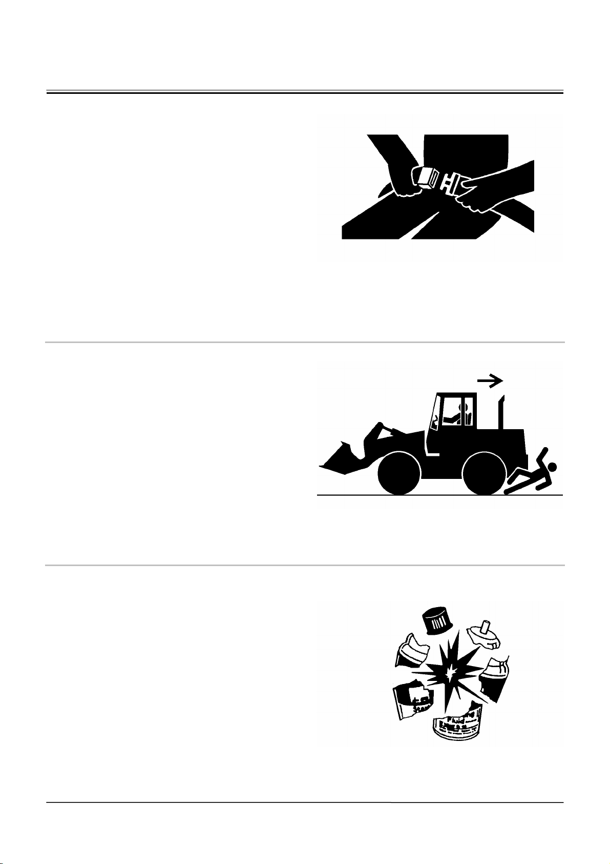
FASTEN YOUR SEAT BELT
• If the machine should overturn, the operator may
become injured and/or thrown from the cab. Additionally the operator may be crushed by the overturning machine, resulting in serious injury or death.
• Prior to operating the machine, thoroughly ex-
amine webbing, buckle and attaching hardware. If
any item is damaged or worn, replace the seat
belt or component before operating the machine.
• Be sure to remain seated with the seat belt se-
curely fastened at all times when the machine is
in operation to minimize the chance of injury from
an accident.
• We recommend that the seat belt be replaced
every three years regardless of its apparent con-
dition.
010-E01A-0237
MOVE AND OPERATE MACHINE SAFELY
• Bystanders can be run over.
• Take extra care not to run over bystanders. Con-
firm the location of bystanders before moving, or
operating the machine.
• Always keep the travel alarm and horn in working
condition (if equipped). It warns people when the
machine starts to move.
• Use a signal person when moving, swinging, or
operating the machine in congested areas. Coor-
dinate hand signals before starting the machine.
• Use appropriate illumination. Check that all lights
are operable before operating the machine. If any
faulty illumination is present, immediately repair it.
011-E01A-0398
HANDLE STARTING AIDS SAFELY
Starting fluid:
• Starting fluid is highly flammable.
• Keep all sparks and flame away when using it.
• Keep starting fluid well away from batteries and
cables.
• Remove container from machine if engine does
not need starting fluid.
• To prevent accidental discharge when storing a
pressurized container, keep the cap on the con-
tainer, and store it in a cool, well-protected loca-
tion.
• Do not incinerate or puncture a starting fluid con-
tainer.
036-E01A-0293-3
SA-237
SA-398
SA-293
SA-6
Page 11
SAFETY
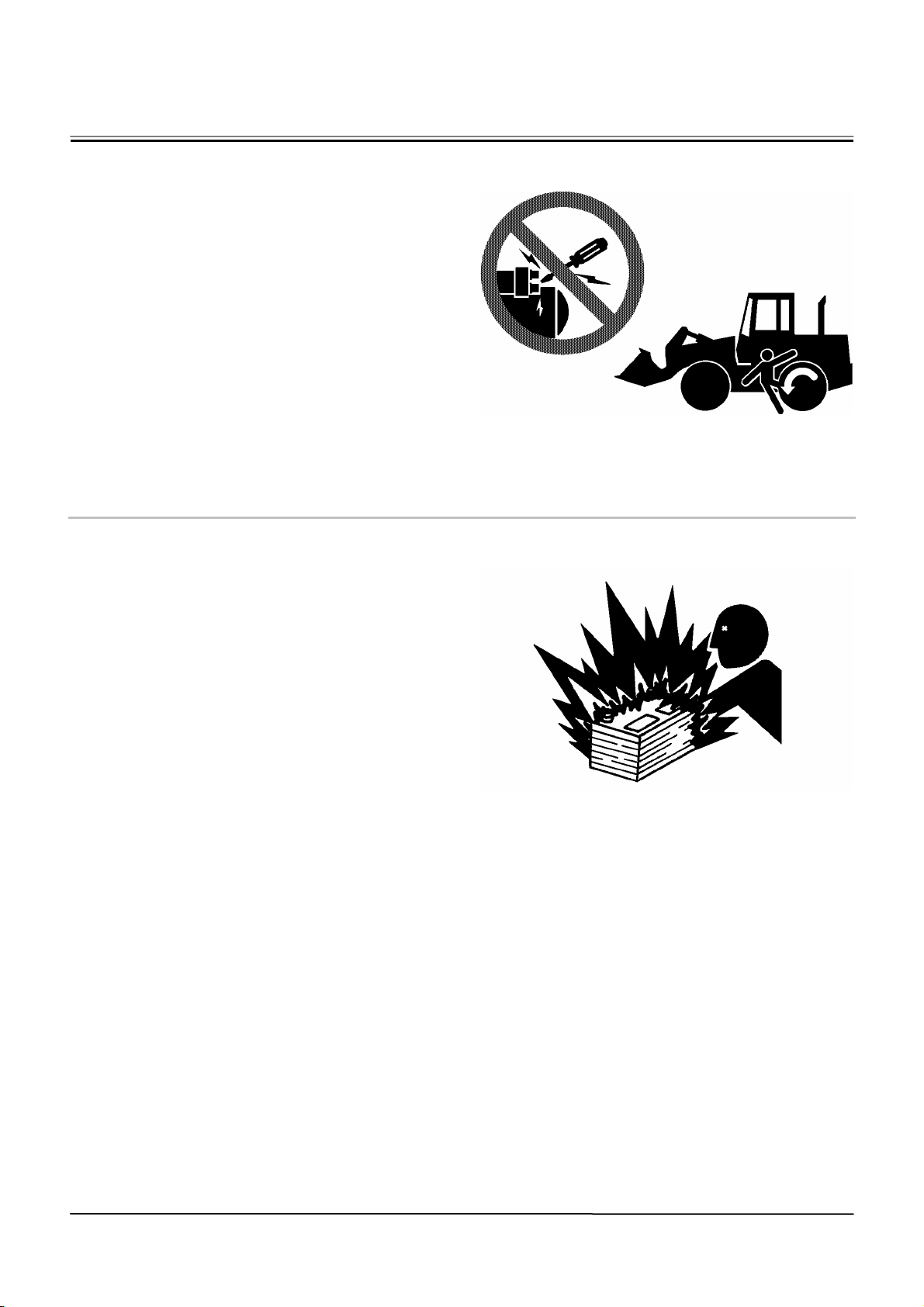
OPERATE ONLY FROM OPERATOR'S
SEAT
• Inappropriate engine starting procedures may cause
the machine to runaway, possibly resulting in serious injury or death.
• Start the engine only when seated in the opera-
tor's seat.
• NEVER start the engine while standing on the
track or on ground.
• Do not start engine by shorting across starter
terminals.
• Before starting the engine, confirm that all control
levers are in neutral.
• Before starting the engine, confirm the safety
around the machine and sound the horn to alert
bystanders.
012-E01B-0431
JUMP STARTING
• Battery gas can explode, resulting in serious injury.
• If the engine must be jump started, be sure to
follow the instructions shown in the “OPERATING
THE ENGINE” chapter in the operator’s manual.
• The operator must be in the operator’s seat so
that the machine will be under control when the
engine starts.
• Jump starting is a two-person operation.
• Never use a frozen battery.
• Failure to follow correct jump starting procedures
could result in a battery explosion or a runaway
machine.
S013-E01A-0032 SA-032
SA-431
SA-032
SA-7
Page 12
SAFETY
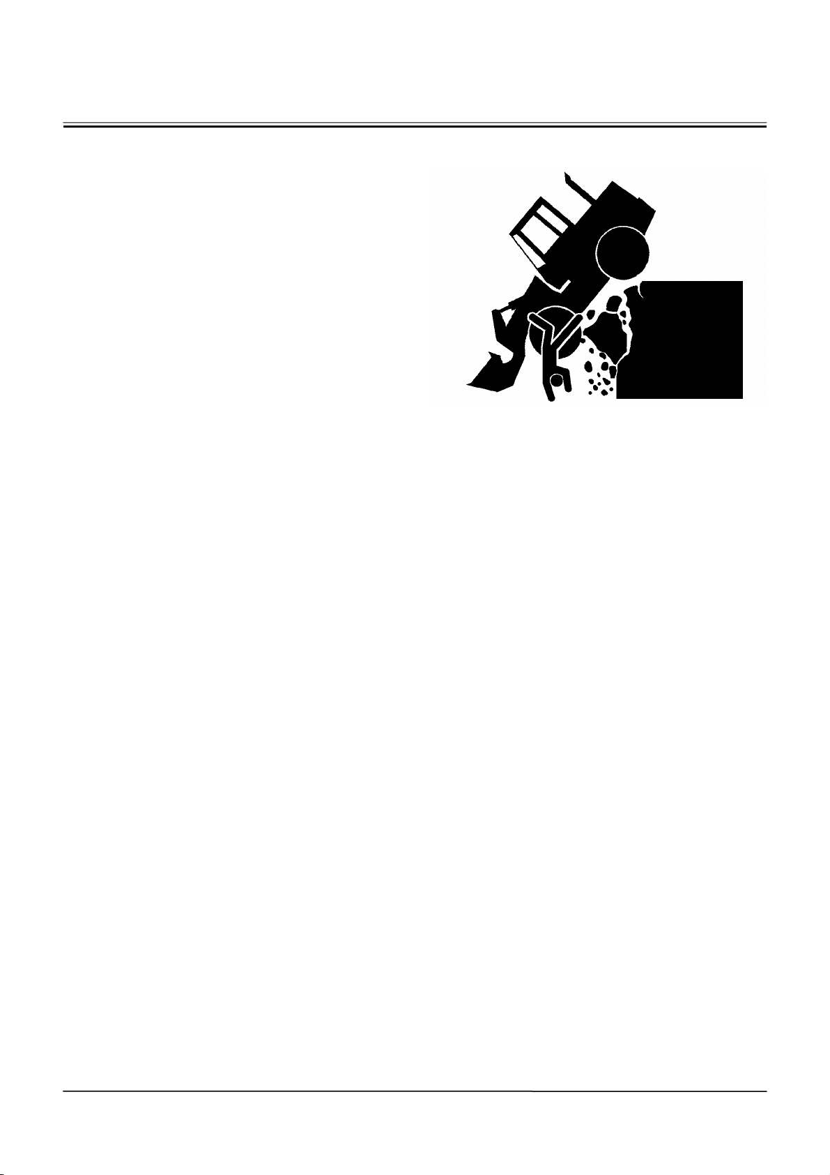
INVESTIGATE JOB SITE BEFOREHAND
• When working at the edge of an excavation or on a
road shoulder, the machine could tip over, possibly
resulting in serious injury or death.
• Investigate the configuration and ground condi-
tions of the job site beforehand to prevent the
machine from falling and to prevent the ground,
stockpiles, or banks from collapsing.
• Make a work plan. Use machines appropriate to
the work and job site.
• Reinforce ground, edges, and road shoulders as
necessary. Keep the machine well back from the
edges of excavations and road shoulders.
• When working on an incline or on a road shoulder,
employ a signal person as required.
• Confirm that your machine is equipped a FOPS
cab before working in areas where the possibility
of falling stones or debris exist.
• When the footing is weak, reinforce the ground
before starting work.
• When working on frozen ground, be extremely
alert. As ambient temperatures rise, footing be-
comes loose and slippery.
• Beware the possibility of fire when operating the
machine near flammable objects such as dry
grass.
015-E01B-0447
SA-447
SA-8
Page 13
SAFETY
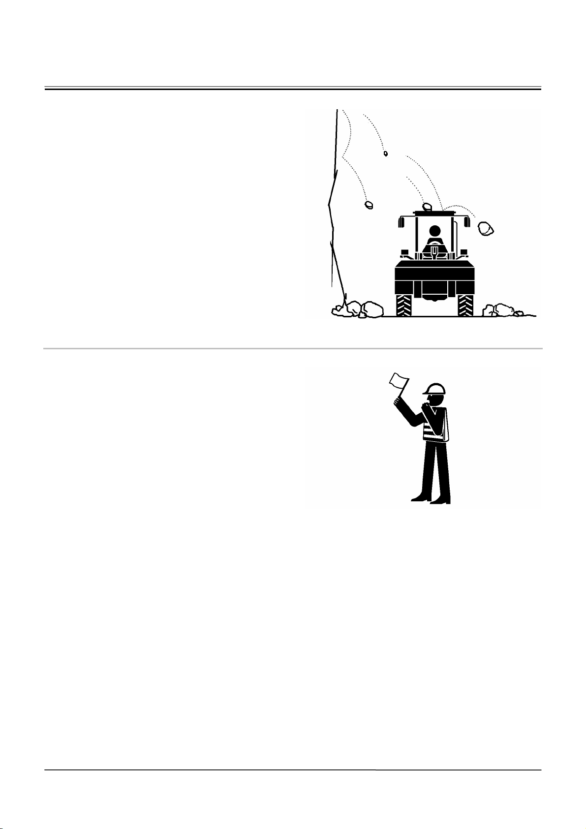
EQUIPMENT OF HEAD GUARD, ROPS,
FOPS
In case the machine is operated in areas where the
possibility of falling stones or debris exist, equip a
head guard, ROPS, or FOPS according to the potential hazardous conditions. (The standard cab for this
machine corresponds to ROPS and FOPS.)
ROPS: Roll-Over Protective Structure
FOPS: Falling Object Protective Structure
PROVIDE SIGNALS FOR JOBS INVOLVING MULTIPLE NUMBERS OF MACHINES
• For jobs involving multiple numbers of machines,
provide signals commonly known by all personnel
involved. Also, appoint a signal person to coordinate
the job site. Make sure that all personnel obey the
signal person’s directions.
018-E01A-0481
SA-521
SA-481
SA-9
Page 14
SAFETY
KEEP RIDERS OFF MACHINE
• Riders on machine are subject to injury such as be-
ing struck by foreign objects and being thrown off
the machine.
• Only the operator should be on the machine.
Keep riders off.
• Riders also obstruct the operator’s view, resulting
in the machine being operated in an unsafe
manner.
014-E01B-0427
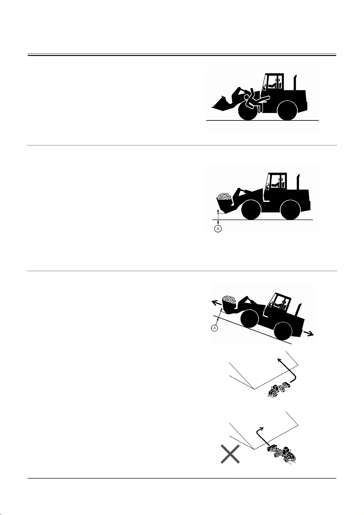
DRIVE SAFELY
• Beware of the possibility of slipping and/or turning
over the machine when driving on a slope.
• When driving on level ground, hold the bucket at
mark (A) 400 to 500 mm above the ground as il-
lustrated.
• Avoid driving over any obstacles.
• Drive the machine slowly when driving on rough
terrain.
• Avoid quick direction changes. Failure to do so
may cause the machine to turn over.
• If the engine stops while driving, the steering
function becomes inoperative. Immediately stop
the machine by applying the bake to prevent
personal accident.
019-E07A-0448
DRIVE MACHINE SAFELY (WORK SITE)
• Before driving the machine, always confirm that the
steering wheel/F-N-R lever direction corresponds to
the direction you wish to drive.
• Be sure to detour around any obstructions.
• Driving on a slope may cause the machine to slip or
overturn, possibly resulting in serious injury or
death.
• When driving up or down a slope, keep the bucket
facing the direction of travel, approximately 200 to
300 mm (approximately 8 to 12 in) (A) above the
ground.
• If the machine starts to skid or becomes unstable,
immediately lower the bucket to the ground and
stop.
• Driving across the face of a slope or steering on a
slope may cause the machine to skid or overturn. If
the direction must be changed, move the machine to
level ground, then, change the direction to ensure
safe operation.
019-E05B-0515
SA-427
SA-448
SA-449
SA-450
SA-451
SA-10
Page 15
SAFETY
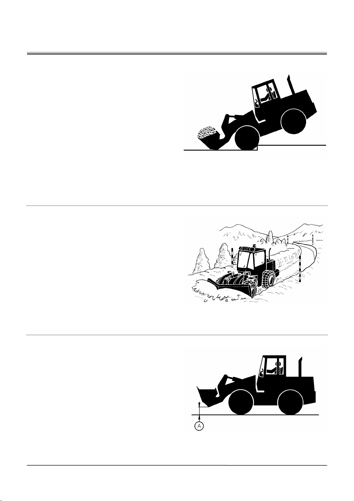
DRIVE SAFELY WITH BUCKET LOADED
• If the machine is incorrectly operated while driving
with the bucket loaded, turning over of the machine
may result. Be sure to follow all the instructions indicated below.
• When driving the machine on a job site with the
bucket loaded, hold the bucket as low as possible
to keep the machine balanced and to have good
visibility.
• Do not exceed the rated load capacity. Always
operate the machine within the rated load capac-
ity.
• Avoid fast starts, stops, and quick turns. Failure to
do so may result in personal injury and/or death.
• Avoid rapid drive direction changes which could
possibly cause personal injury and/or death.
051-E02A-0400
DRIVE ON SNOW SAFELY
• Beware of the possibility of slipping or turning over
the machine when driving on frozen snow surfaces.
• The machine may slip more easily than expected
on frozen snow surfaces even if the inclination is
small. Reduce speed when driving. Avoid fast
starts, stops and quick turns.
• Road shoulder and/or set-up utilities covered with
snow are difficult to locate. Be sure where they
are before removing snow.
• Be sure to use tire chains when driving on snow.
• Avoid applying the brake for quick stops on snow.
If a quick stop is required, lower the bucket to the
ground.
052-E02A-0452
TRAVEL ON PUBLIC ROADS SAFELY
• This machine is not allowed to drive on public loads
with the bucket loaded.
• Be sure to empty the bucket.
• Hold the bucket at mark (A) 400 to 500 mm above
the road surface as illustrated.
053-E02A-0453
SA-400
SA-452
SA-11
SA-453
Page 16
SAFETY
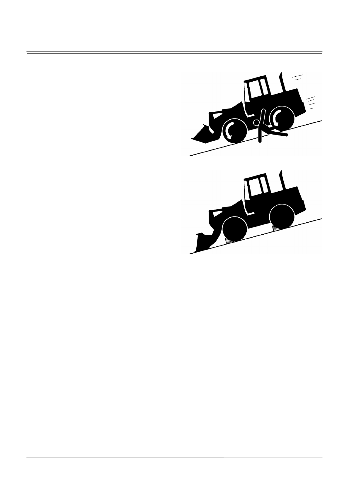
AVOID INJURY FROM ROLLAWAY ACCIDENTS
• Death or serious injury may result if you attempt to
mount or stop a moving machine.
To avoid rollaways:
• Select level ground when possible to park ma-
chine.
• Do not park the machine on a grade.
• Lower the bucket to the ground.
• Place the F-N-R lever in neutral, and put the park
brake switch in the ON (parking brake) position.
• Run the engine at slow idle speed without load for
5 minutes to cool down the engine.
• Stop the engine and remove the key from the key
switch.
• Pull the lock lever to LOCK position.
• Block both tires and lower the bucket to the
ground.
• Position the machine to prevent rolling.
• Park a reasonable distance from other machines.
020-E02A-0516
SA-457
SA-458
SA-12
Page 17
SAFETY
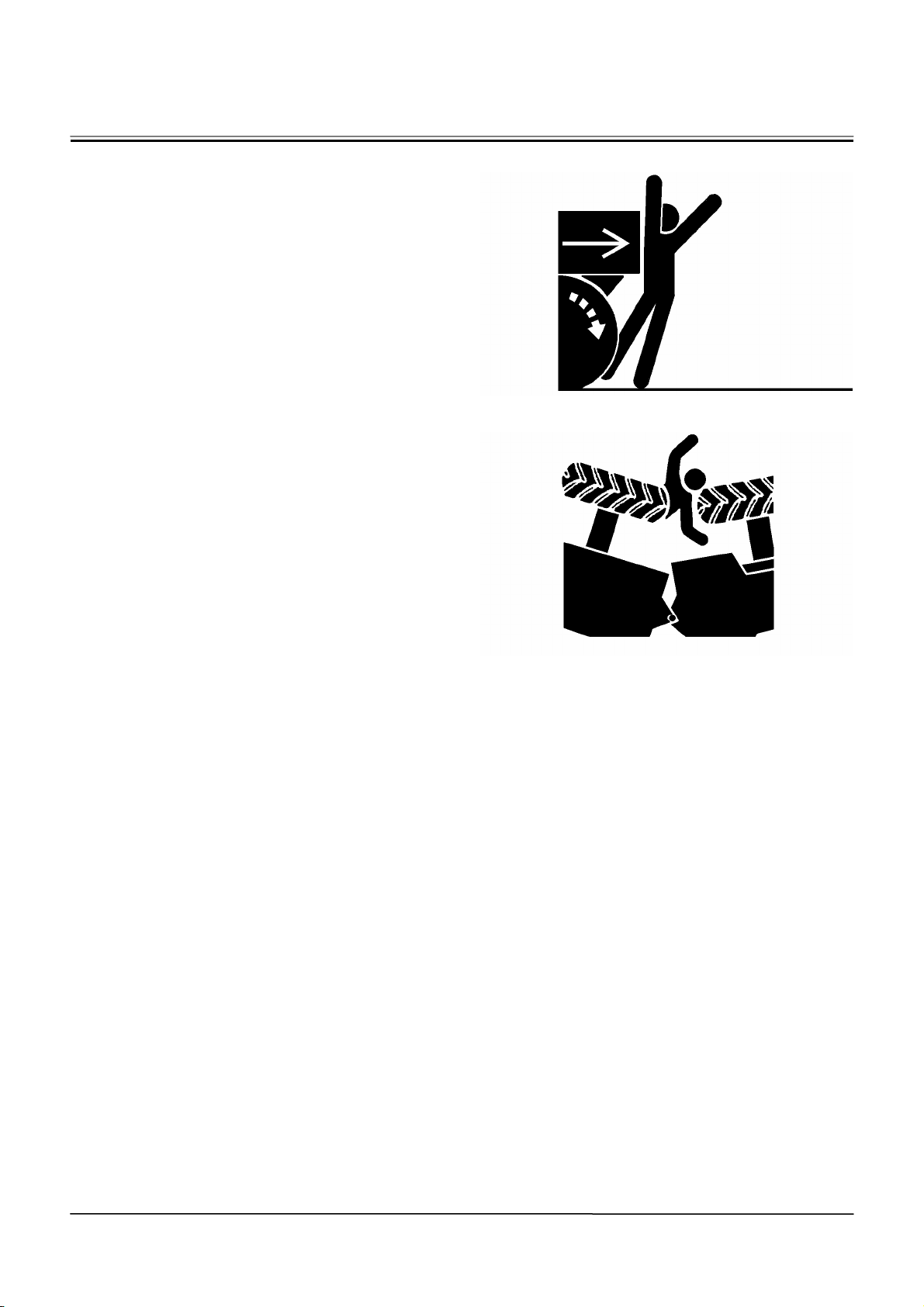
AVOID ACCIDENTS FROM BACKING UP
AND TURNING
• Make sure no one is working under or close to the
machine before backing up or turning the machine
to avoid personal injury and/or death by being run
over or entangled in the machine.
• Keep all personnel away from the machine by
sounding the horn and/or using hand signals. Use
extra care to be sure no one is in from the articu-
lation area before turning the machine.
• Keep windows, mirrors, and lights in good condi-
tion.
• Reduce travel speed when dust, heavy rain, fog,
etc., reduce the visibility.
• In case good visibility is not obtained, use a signal
person to guide you.
021-E02A-0517
SA-383
SA-312
SA-13
Page 18
SAFETY
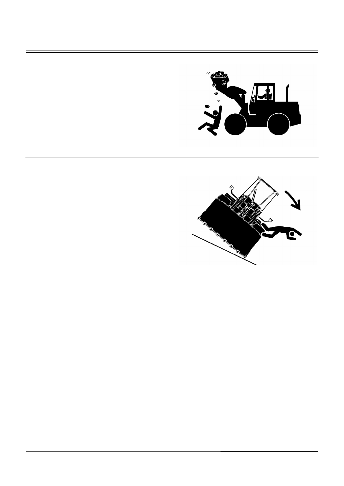
AVOID POSITIONING BUCKET OVER
ANYONE
• Never allow the bucket to pass over co-workers
and/or the dump truck operator’s cab. Falling soil
from the bucket or contact with bucket may cause
serious personal accidents and/or damage to the
machine.
• Avoid carrying the bucket over the co-workers to
ensure safe operation.
023-E02A-0518
AVOID TIPPING
DO NOT ATTEMPT TO JUMP CLEAR OF TIPPING
MACHINE. MACHINE WILL TIP OVER FASTER
THAN YOU CAN JUMP FREE, POSSIBLY RESULTING IN SERIOUS PERSONAL INJURY OR
DEATH. IF TIPPING OVER OF THE MACHINE IS
PREDICTED, SECURELY HOLD THE STEERING
WHEEL TO PREVENT YOUR BODY FROM BEING
THROWN OUT OF THE MACHINE.
SA-518
MACHINE WILL TIP OVER FASTER THAN YOU
CAN JUMP FREE
FASTEN YOUR SEAT BELT
• The danger of tipping is always present when oper-
ating on a grade, possibly resulting in serious injury
or death.
To avoid tipping:
• Be extra careful before operating on a grade.
• Prepare machine operating area flat.
• Keep the bucket low to the ground and close to
the machine.
• Reduce operating speeds to avoid tipping or slip-
ping.
• Avoid changing direction when traveling on
grades.
• NEVER attempt to travel across a grade steeper
than 5 degrees if crossing the grade is unavoid-
able.
• Reduce swing speed as necessary when swing-
ing loads.
• Be careful when working on frozen ground.
• Temperature increases will cause the ground to
become soft and make ground travel unstable.
SA-463
SA-14
Page 19
SAFETY
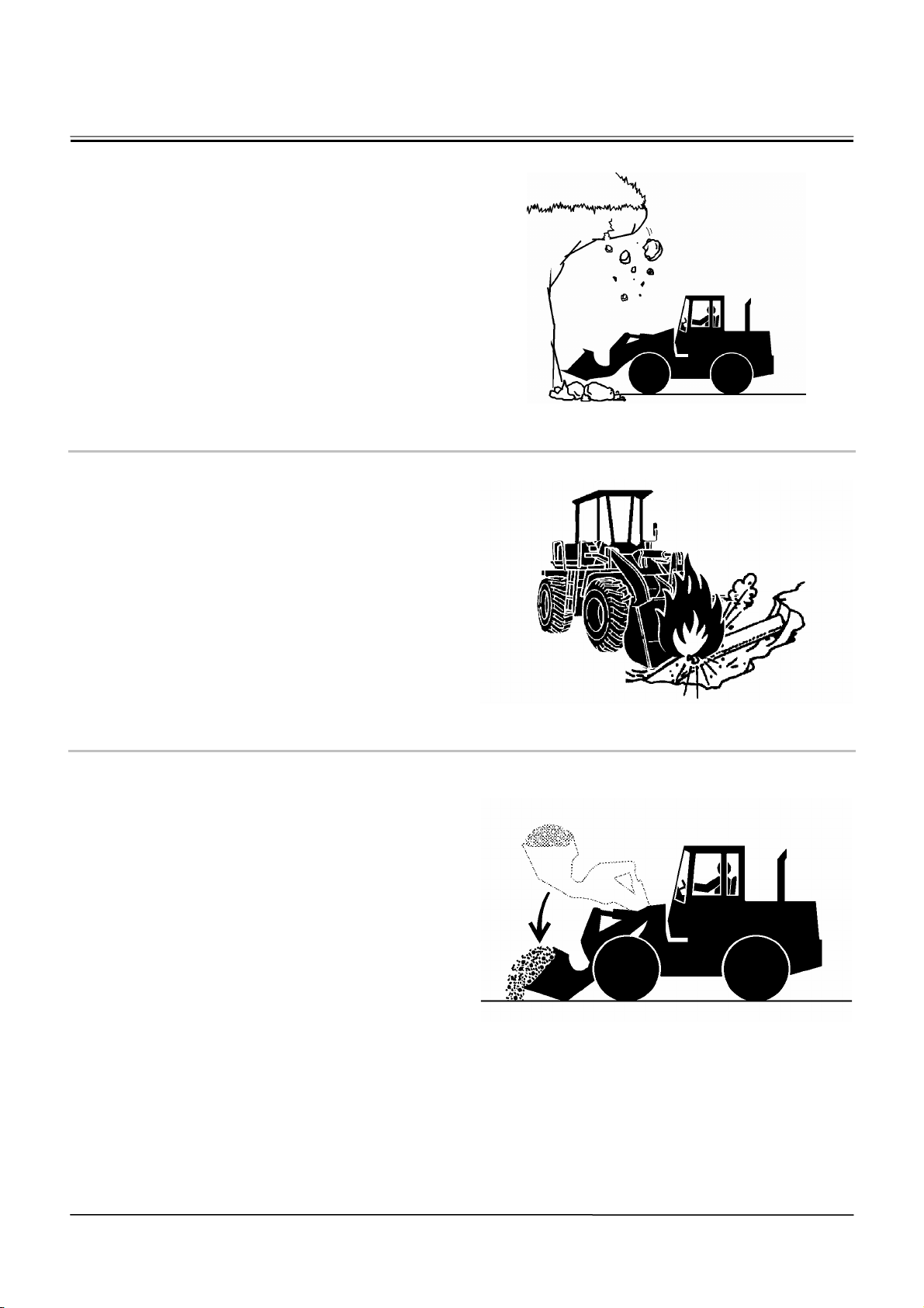
NEVER UNDERCUT A HIGH BANK
• The edges could collapse or a land slide could occur
causing serious injury or death.
026-E01A-0519
DIG WITH CAUTION
Before digging, check the location of cables, gas lines,
and water lines.
027-E01A-0396
SA-519
PERFORM TRUCK LOADING SAFELY
• Do not operate the machine involuntarily. Unex-
pected machine movement may cause personal injury and/or death.
• Do not lower the bucket with the loader control
lever in the FLOAT position. The bucket may free
fall, possibly causing personal injury and/or death.
• Always select a level surface for truck loading.
028-E01A-397
SA-396
SA-397
SA-15
Page 20
SAFETY
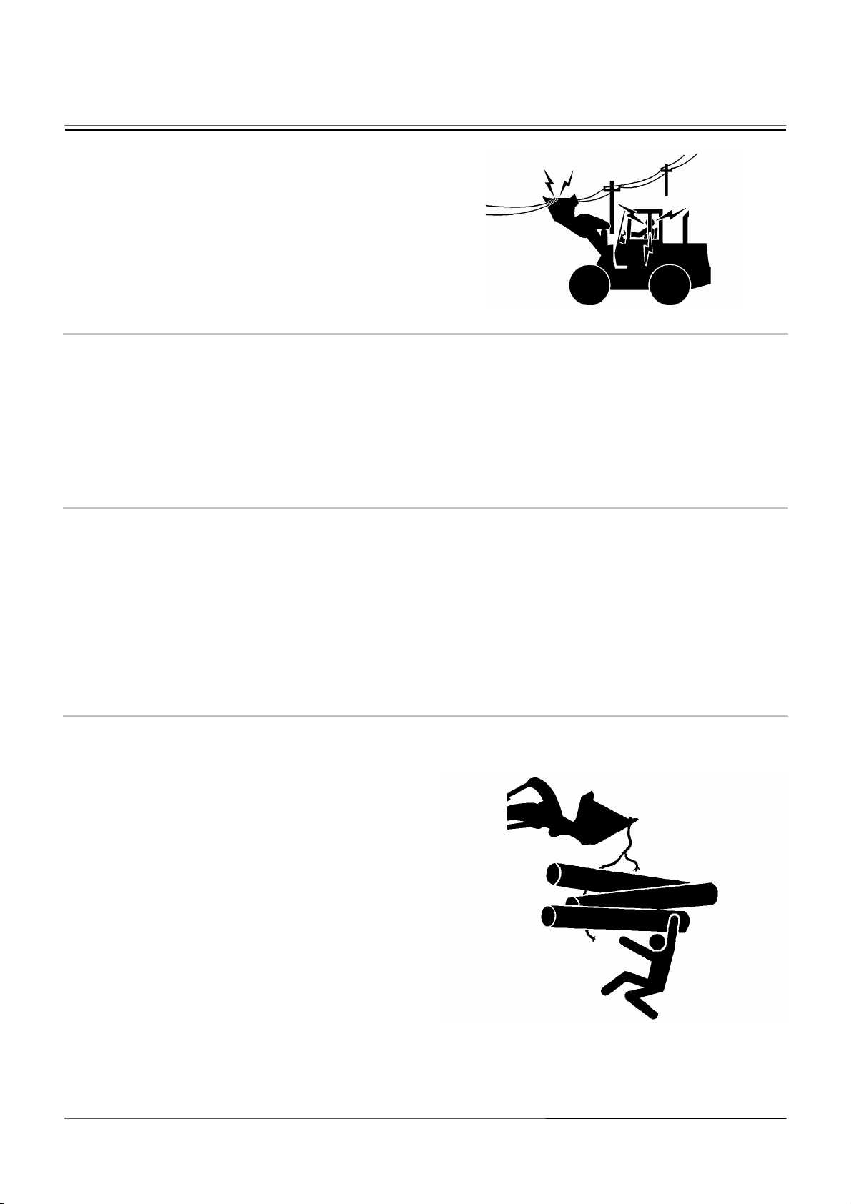
AVOID POWER LINES
Serious injury or death can result from contact with
electric lines.
Never move any part of the machine or load closer to
any electric line than 3 m (10 ft) plus twice the line
insulator length.
29-E01A-0455
PRECAUTIONS FOR OPERATION
• If the front attachment or any part of the machine
comes in contact with an overhead obstacle, both
the machine and the overhead obstacle may become damaged, and personal injury may result.
• Take care to avoid coming in contact with over-
head obstacles with the bucket or arm during op-
eration.
PRECAUTIONS FOR LIGHTENING
• The machine is vulnerable to lighting strikes.
• In the event of an electrical storm, immediately
stop operation, and lower the bucket to the
ground. Evacuate to a safe place far away from
the machine.
• After the electrical storm has passed, check all of
the machine safety devices for any failure. If any
failed safety devices are found, operate the ma-
chine only after repairing them.
OBJECT HANDLING
• If a lifted load should fall, any person nearby may be
struck by the falling load or may be crushed underneath it, resulting in serious injury or death.
• When using the machine for craning operations,
be sure to comply with all local regulations.
• Do not use damaged chains or frayed cables,
sables, slings, or ropes.
• Before craning, position the upperstructure with
the position of the bucket support located on the
chassis at the front.
• Move the load slowly and carefully. Never move it
suddenly.
• Keep all persons well away from the load.
• Never move a load over a person's head.
• Do not allow anyone to approach the load until it
is safely and securely situated on supporting
blocks or on the ground.
• Never attach a sling or chain to the bucket teeth.
They may come off, causing the load to fall.
032-E01A-0132
SA-455
SA-132
SA-16
Page 21
SAFETY
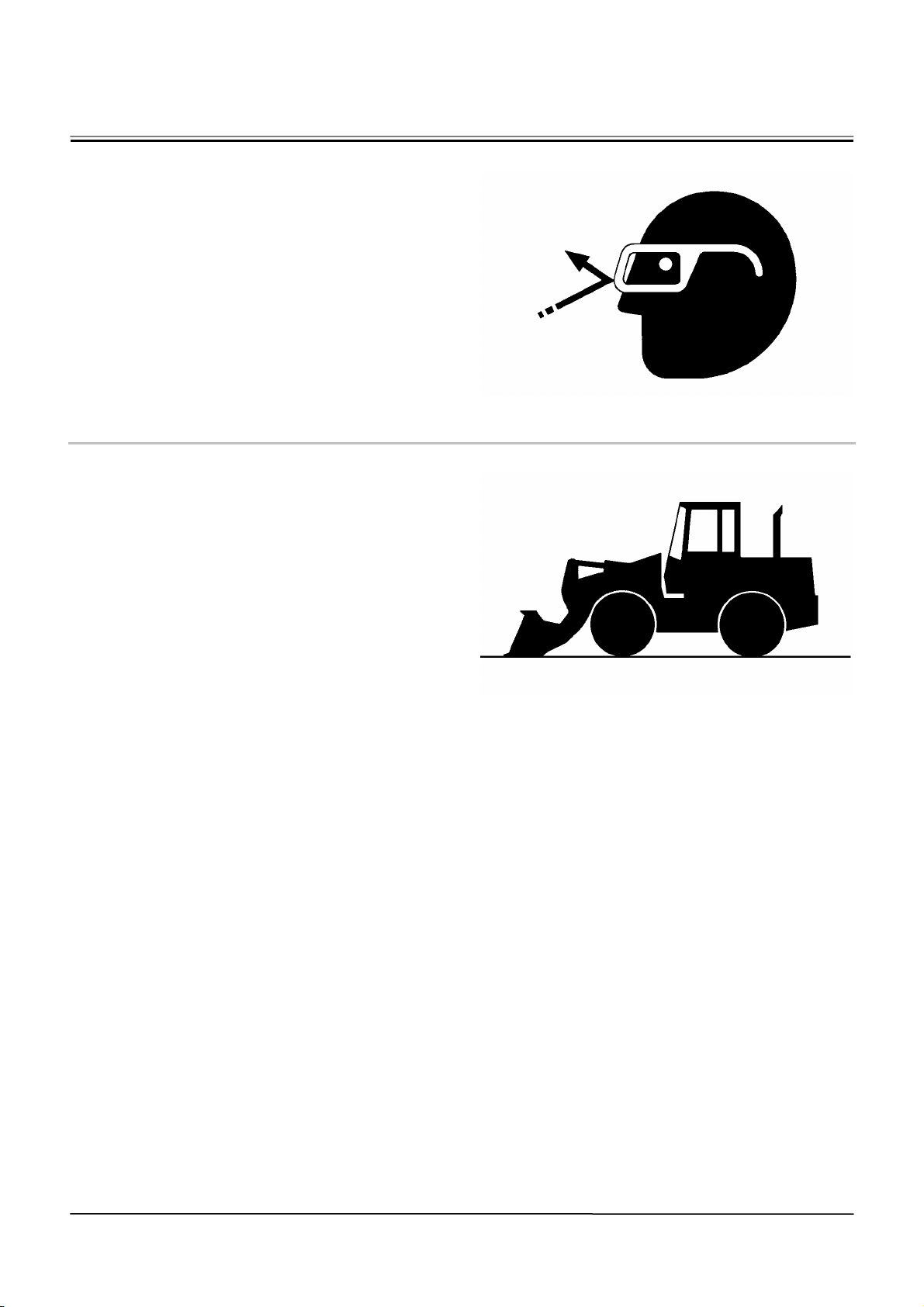
PROTECT AGAINST FLYING DEBRIS
• If flying debris hit eyes or any other part of the body,
serious injury may result.
• Guard against injury from flying pieces of metal or
debris; wear goggles or safety glasses.
• Keep bystanders away from the working area
before striking any object.
031-E01A-0432
PARK MACHINE SAFELY
To avoid accidents:
• Park machine on a firm, level surface.
• Lower bucket to the ground.
• Place the F-N-R lever in neutral, and put the park
brake switch in the ON (parking brake) position.
• Run engine at slow idle speed without load for 5
minutes.
• Turn key switch to OFF to stop engine.
• Remove the key from the key switch.
• Lower the lock lever to the LOCK position.
• Close windows, roof vent, and cab door.
• Lock all access doors and compartments.
033-E07B-0456
SA-432
SA-456
SA-17
Page 22
SAFETY
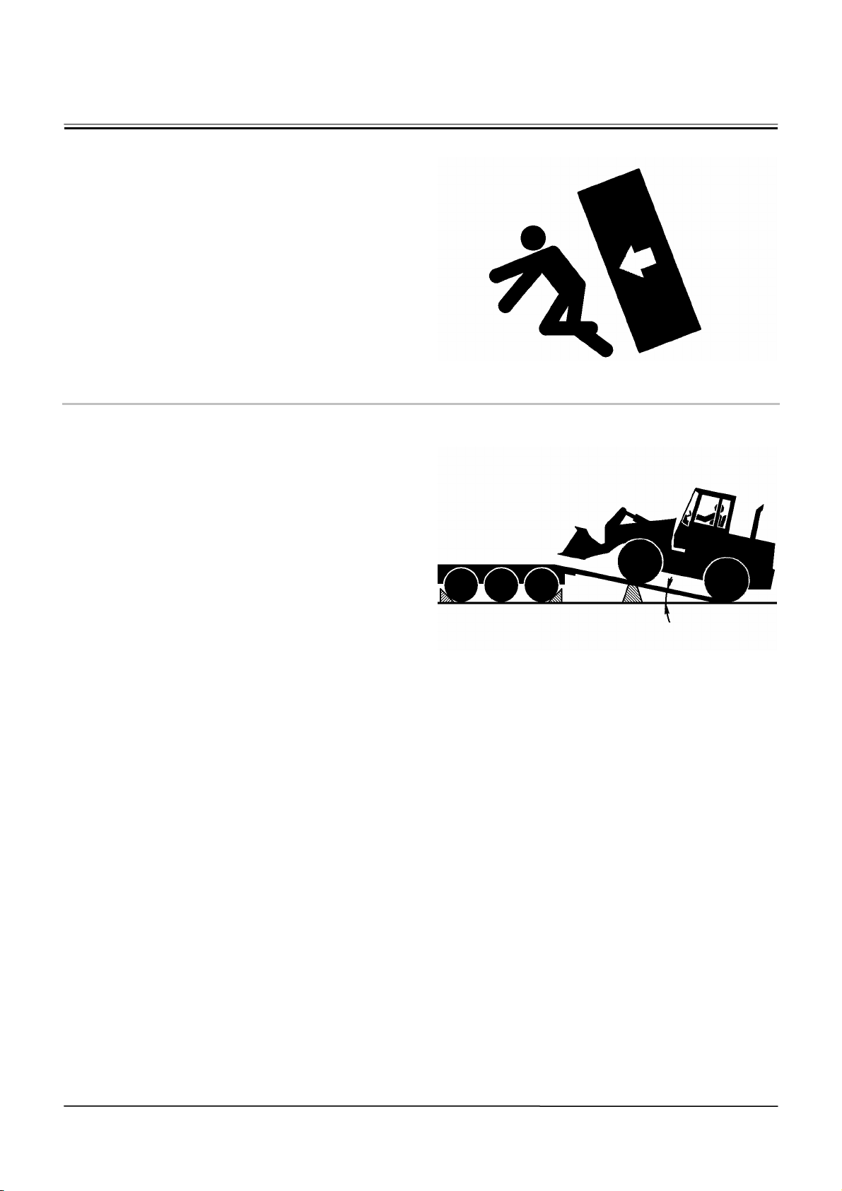
STORE ATTACHMENTS SAFELY
• Stored attachments such as buckets, hydraulic
hammers, and blades can fall and cause serious
injury or death.
• Securely store attachments and implements to
prevent falling. Keep children and bystanders
away from storage areas.
504-E01A-0034
TRANSPORT SAFELY
• Take care the machine may turn over when loading
or unloading the machine onto or off of a truck or
trailer.
• Observe the related regulations and rules for safe
transportation.
• Select an appropriate truck or trailer for the ma-
chine to be transported.
• Be sure to use a signal person.
• Always follow the following precautions for load-
ing or unloading:
1. Select solid and level ground.
2. Always use a ramp or deck strong enough to
support the machine weight.
3. Use the low speed gear.
4. Never steer the machine while on the ramp. If the
traveling direction must be changed while the
ramp, unload the machine from the ramp, reposition the machine on the ground, then try loading
again.
5. After loading, install the lock bar to securely hold
the articulation mechanism.
6. Wedge the front and rear of tires. Securely hold
the machine to the truck or trailer deck with wire
ropes.
Be sure to further follow the details described in the
TRANSPORTING section.
035-E07A-0454
SA-034
Less than 15°
SA-454
SA-18
Page 23
SAFETY
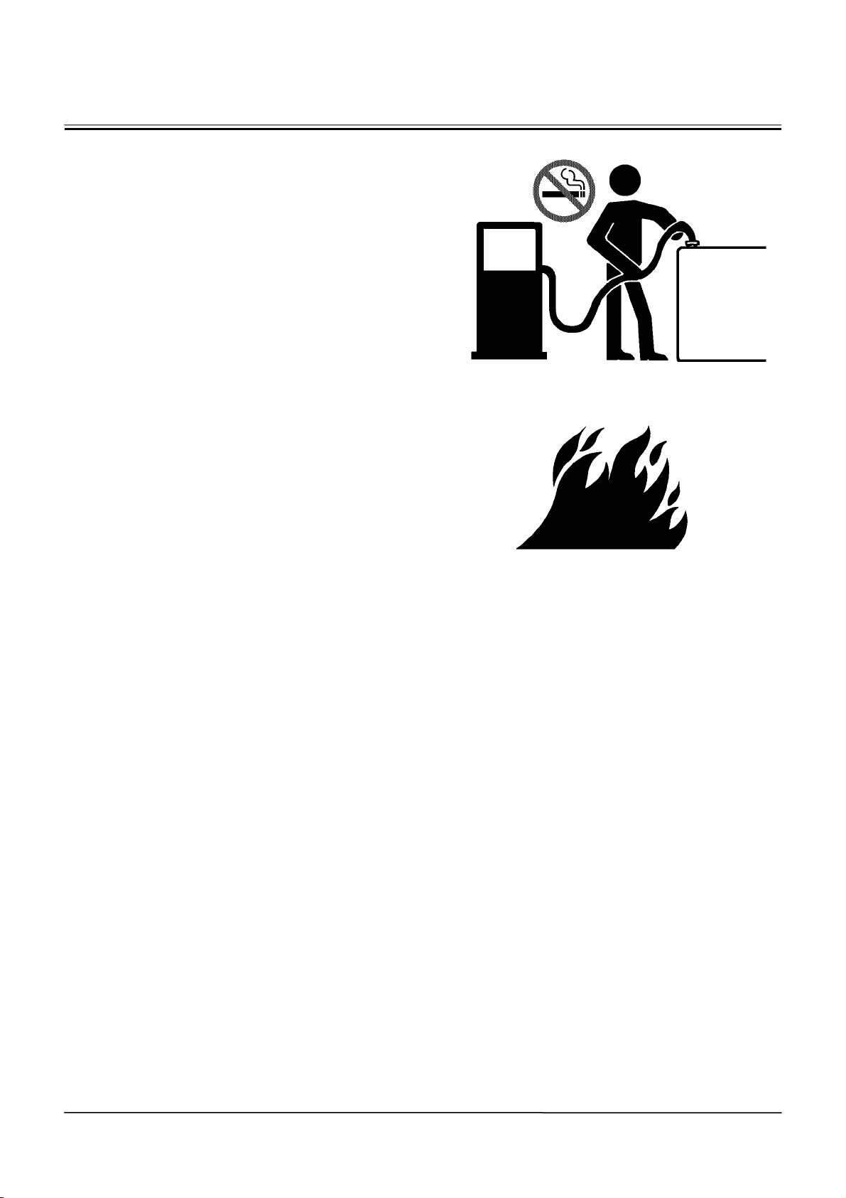
HANDLE FLUIDS SAFELY-AVOID FIRES
• Handle fuel with care; it is highly flammable. If fuel
ignites, an explosion and/or a fire may occur, possibly resulting in serious injury or death.
• Do not refuel the machine while smoking or when
near open flame or sparks.
• Always stop the engine before refueling the ma-
chine.
• Fill the fuel tank outdoors.
• All fuels, most lubricants, and some coolants are
flammable.
• Store flammable fluids well away from fire haz-
ards.
• Do not incinerate or puncture pressurized con-
tainers.
• Do not store oily rags; they can ignite and burn
spontaneously.
• Securely tighten the fuel and oil filler cap.
034-E01A-0496
SA-018
SA-019
SA-19
Page 24
SAFETY
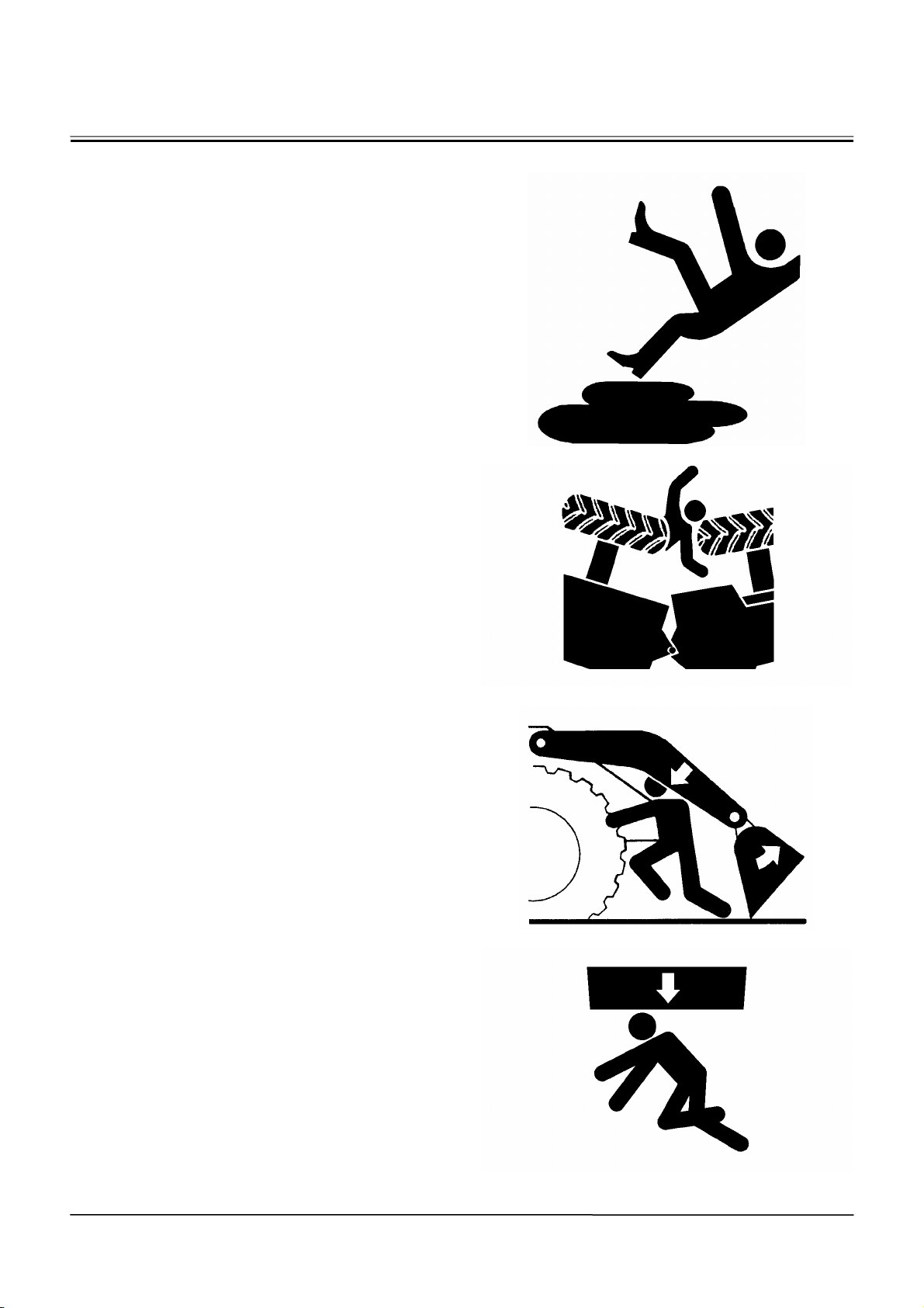
PRACTICE SAFE MAINTENANCE
To avoid accidents:
• Understand service procedures before starting
work.
• Keep the work area clean and dry.
• Do not spray water or steam inside cab.
• Never lubricate or service the machine while it is
moving.
• Keep hands, feet and clothing away from
power-driven parts.
Before servicing the machine:
1. Park the machine on a level surface.
2. Lower the bucket to the ground.
3. Turn the auto-idle switch off.
4. Run the engine at slow idle speed without load for
5 minutes.
5. Turn the key switch to OFF to stop engine.
6. Relieve the pressure in the hydraulic system by
moving the control levers several times.
7. Remove the key from the switch.
8. Attach a “Do Not Operate” tag on the control
lever.
9. Lower the lock lever to the LOCK position.
10. Lock bar connects the front and rear frames.
11. Allow the engine to cool.
• If a maintenance procedure must be performed
with the engine running, do not leave machine
unattended.
• Never work under a machine raised by the lift
arm.
• Inspect certain parts periodically and repair or re-
place as necessary. Refer to the section discussing that part in the “MAINTENANCE” chapter of
operator`s manual.
• Keep all parts in good condition and properly in-
stalled.
• Fix damage immediately. Replace worn or broken
parts. Remove any buildup of grease, oil, or debris.
• When cleaning parts, always use nonflammable
detergent oil. Never use highly flammable oil such
as fuel oil and gasoline to clean parts or surfaces.
• Disconnect battery ground cable (-) before mak-
ing adjustments to electrical systems or before
performing welding on the machine.
500-E02C-0520
SA-028
SA-312
SA-134
SA-20
SA-527
Page 25
SAFETY
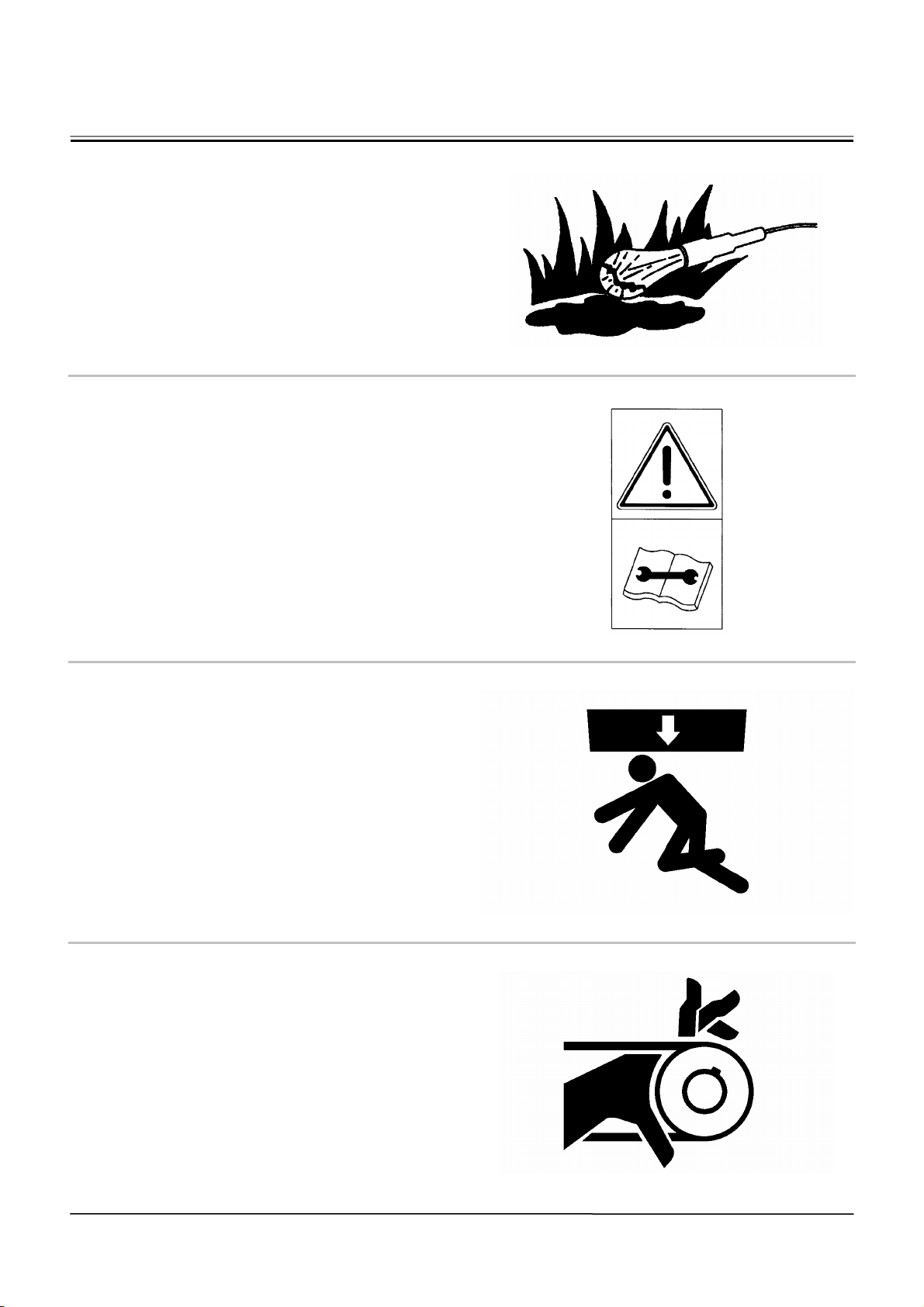
• Sufficiently illuminate the work site. Use a main-
tenance work light when working under or inside
the machine.
• Always use a work light protected with a guard. In
case the light bulb is broken, spilled fuel, oil, antifreeze fluid, or window washer fluid may catch fire.
WARN OTHERS OF SERVICE WORK
• Unexpected machine movement can cause serious
injury.
• Before performing any work on the machine, at-
tach a “Do Not Operate” tag on the control lever.
This tag is available from your authorized dealer.
501-E01A-0287
SA-037
SUPPORT MACHINE PROPERLY
• Never attempt to work on the machine without se-
curing the machine first.
• Always lower the attachment to the ground before
you work on the machine.
• If you must work on a lifted machine or attach-
ment, securely support the machine or attachment. Do not support the machine on cinder
blocks, hollow tires, or props that may crumble
under continuous load. Do not work under a machine that is supported solely by a jack.
519-E01A-0527
STAY CLEAR OF MOVING PARTS
• Entanglement in moving parts can cause serious
injury.
• To prevent accidents, care should be taken to
ensure that hands, feet, clothing, jewelry and hair
do not become entangled when working around
rotating parts.
502-E01A-0026
SS2045102
SA-527
SA-026
SA-21
Page 26
SAFETY
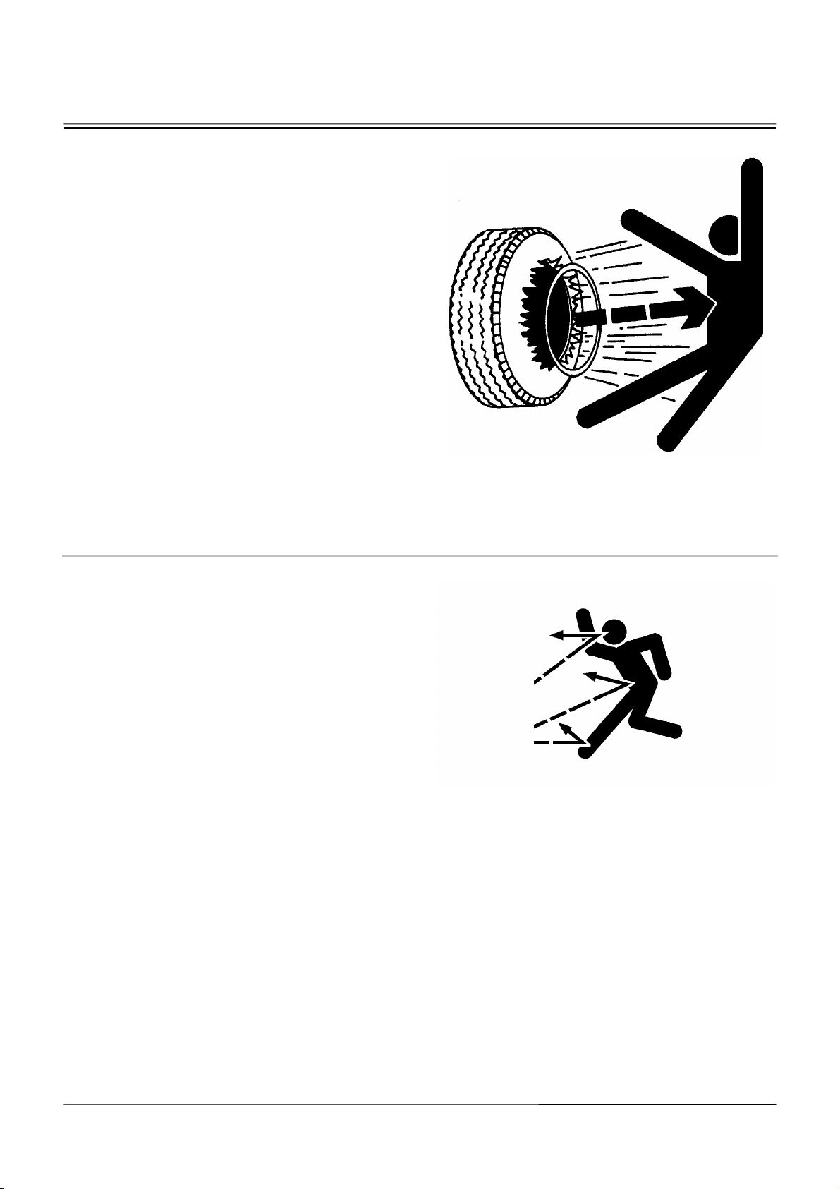
SUPPORT MAINTENANCE PROPERLY
• Explosive separation of a tire and rim parts can
cause serious injury or death.
• Do not attempt to mount a tire unless you have
the proper equipment and experience to perform
the job. Have it done by your authorized dealer or
a qualified repair service.
• Always maintain the correct tire pressure. DO
NOT inflate tire above the recommended pressure.
• When inflating tires, use a chip-on chuck and ex-
tension hose long enough to allow you to stand to
one side and not in front of or over the tire assembly. Use a safety cage it available.
• Inspect tires and wheels daily. Do not operate with
low pressure, cuts bubbles, damaged rims, or
missing lug bolts and nuts.
• Never cut or weld on an inflated tire or rim as-
sembly. Heat from welding could cause an increase in pressure and may result in tire explosion.
521-E02A-0249
PREVENT PARTS FROM FLYING
• Travel reduction gears are under pressure.
• As pieces may fly off, be sure to keep body and
face away from AIR RELEASE PLUG to avoid
injury.
• GEAR OIL is hot. Wait for GEAR OIL to cool, then
gradually loosen AIR RELEASE PLUG to release
pressure.
503-E03A-0344
SA-249
SA-344
SA-22
Page 27
SAFETY
PREVENT BURNS
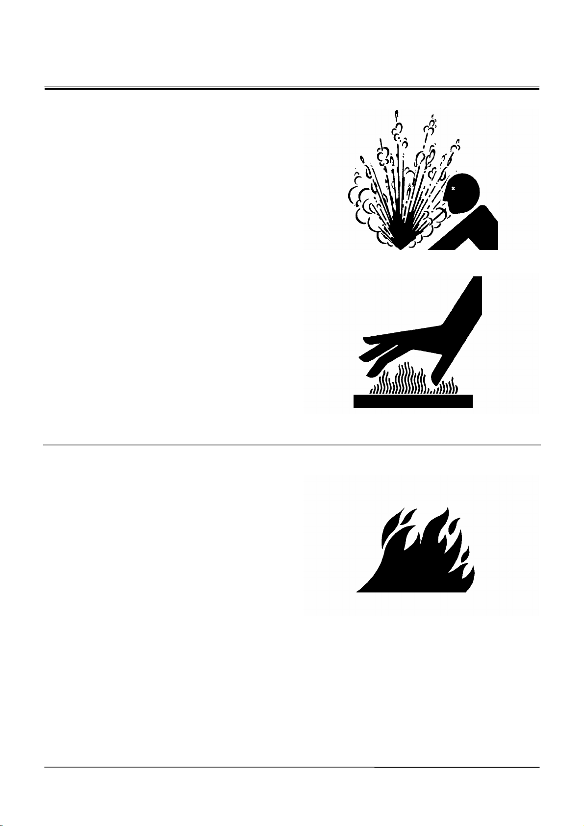
Hot spraying fluids:
• After operation, engine coolant is hot and under
pressure. Hot water or steam is contained in the
engine, radiator and heater lines.
Skin contact with escaping hot water or steam can
cause severe burns.
• To avoid possible injury from hot spraying water.
DO NOT remove the radiator cap until the engine
is cool. When opening, turn the cap slowly to the
stop. Allow all pressure to be released before
removing the cap.
• The hydraulic oil tank is pressurized. Again, be
sure to release all pressure before removing the
cap.
Hot fluids and surfaces:
• Engine oil, gear oil and hydraulic oil also become
hot during operation.
The engine, hoses, lines and other parts become
hot as well.
• Wait for the oil and components to cool before
starting any maintenance or inspection work.
505-E01B-0498
REPLACE RUBBER HOSES PERIODICALLY
• Rubber hoses that contain flammable fluids under
pressure may break due to aging, fatigue, and abrasion. It is very difficult to gauge the extent of deterioration due to aging, fatigue, and abrasion of rubber hoses by inspection alone.
• Periodically replace the rubber hoses. (See the
page of “Periodic replacement of parts” in the operator’s manual.)
• Failure to periodically replace rubber hoses may
cause a fire, fluid injection into skin, or the front attachment to fall on a person nearby, which may result in severe burns, gangrene, or otherwise serious
injury or death.
S506-E01A-0019
SA-039
SA-225
SA-019
SA-23
Page 28
SAFETY
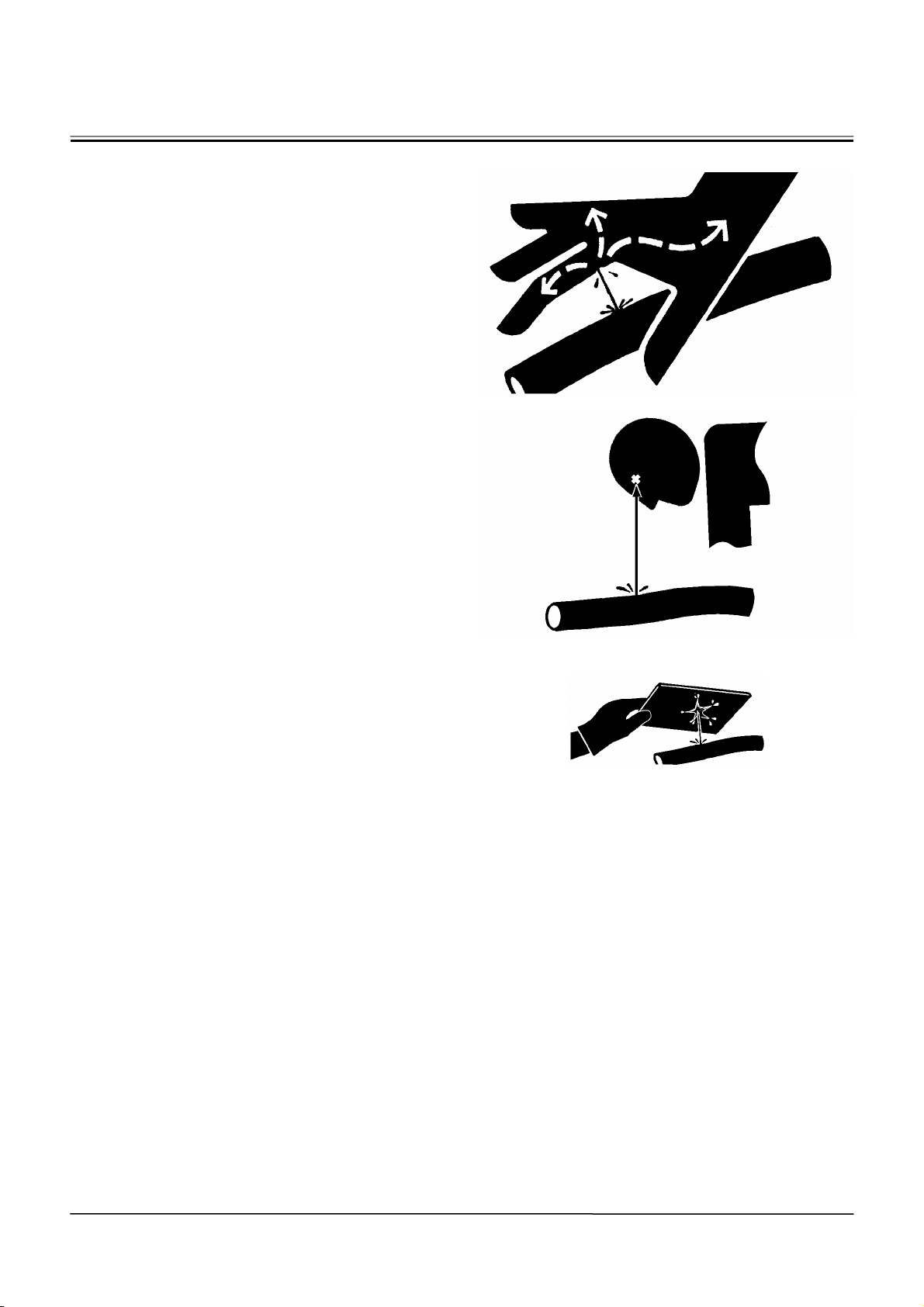
AVOID HIGH-PRESSURE FLUIDS
• Fluids such as diesel fuel or hydraulic oil under
pressure can penetrate the skin or eyes causing serious injury, blindness or death.
• Avoid this hazard by relieving pressure before
disconnecting hydraulic or other lines.
• Tighten all connections before applying pressure.
• Search for leaks with a piece of cardboard; take
care to protect hands and body from
high-pressure fluids. Wear a face shield or goggles for eye protection.
• If an accident occurs, see a doctor familiar with
this type of injury immediately. Any fluid injected
into the skin must be surgically removed within a
few hours or gangrene may result.
507-E03A-0499
SA-031
SA-292
SA-044
SA-24
Page 29

SAFETY
PREVENT FIRES
Check for Oil Leaks:
• Fuel, hydraulic oil and lubricant leaks can lead to
fires.
• Check for oil leaks due to missing or loose clamps,
kinked hoses, lines or hoses that rub against each
other, damage to the oil-cooler, and loose
oil-cooler flange bolts.
• Tighten, repair or replace any missing, loose or
damaged clamps, lines, hoses, oil-cooler and
oil-cooler flange bolts.
• Do not bend or strike high-pressure lines.
• Never install bent or damaged lines, pipes, or
hoses.
Check for Shorts:
• Short circuits can cause fires.
• Clean and tighten all electrical connections.
• Check before each shift or after eight(8) to ten(10)
hours operation for loose, kinked, hardened or
frayed electrical cables and wires.
• Check before each shift or after eight(8) to ten(10)
hours operation for missing or damaged terminal
caps.
• DO NOT OPERATE MACHINE if cable or wires
are loose, kinked, etc..
Clean up Flammables:
• Spilled fuel and oil, and trash, grease, debris, ac-
cumulated coal dust, and other flammables may
cause fires.
• Prevent fires by inspecting and cleaning the ma-
chine daily and by removing spilled or accumulated flammables immediately.
Check Key Switch:
• If a fire breaks out, failure to stop the engine will
escalate the fire, hampering fire fighting.
Always check key switch function before operating
the machine every day:
1. Start the engine and run it at slow idle.
SA-019
2. Turn the key switch to the OFF position to confirm
that the engine stops.
• If any abnormalities are found, be sure to repair
them before operating the machine.
508-E02B-0019
Check Heat Shields:
• Damaged or missing heat shields may lead to fires.
• Damaged or missing heat shields must be re-
paired or replaced before operating the machine.
508-E02A-0393
SA-25
Page 30
SAFETY
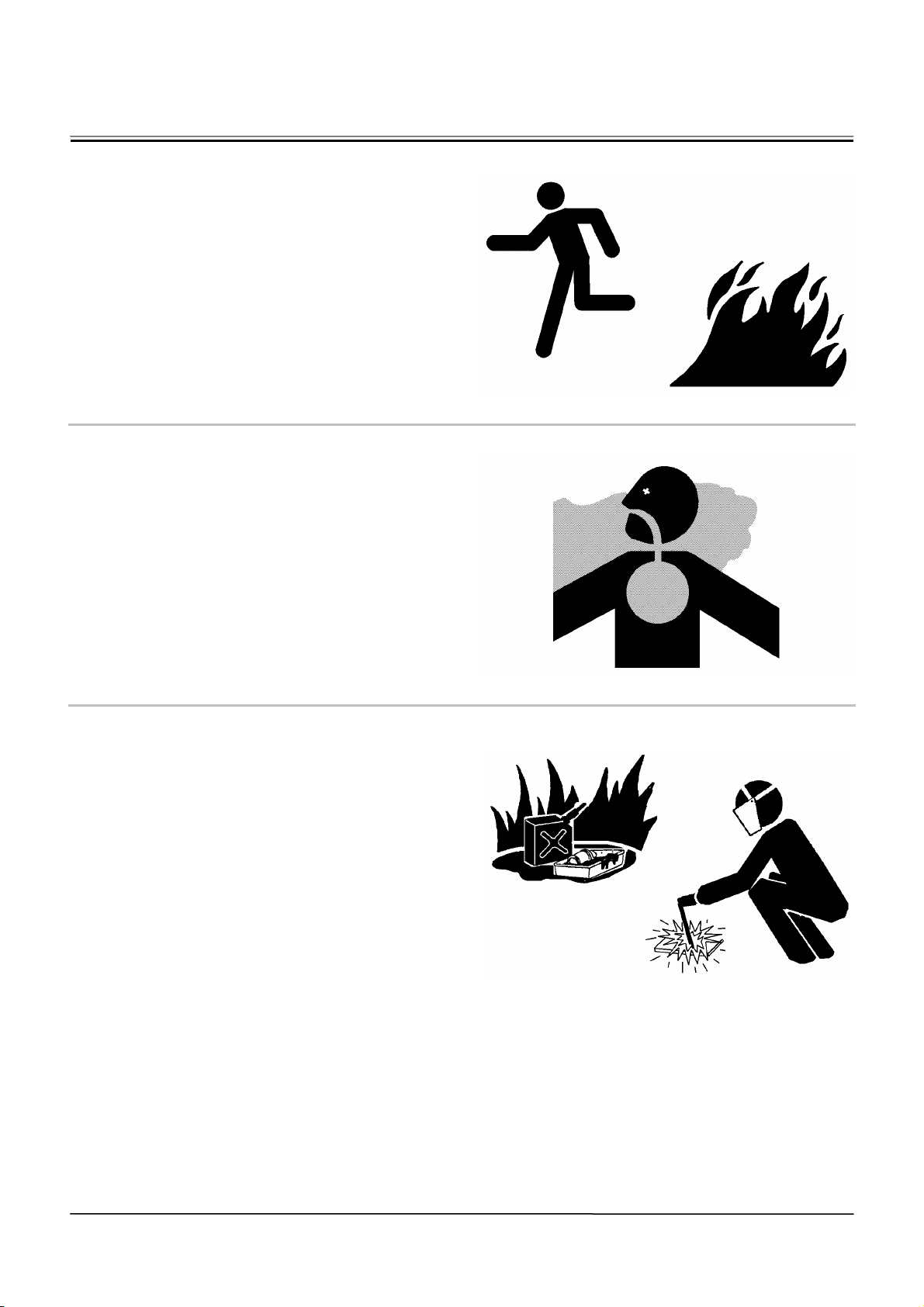
EVACUATING IN CASE OF FIRE
• If a fire breaks out, evacuate the machine in the fol-
lowing way:
• Stop the engine by turning the key switch to the
OFF position if there is time.
• Use a fire extinguisher if there is time.
• Exit the machine.
518-E01A-0393
BEWARE OF EXHAUST FUMES
• Prevent asphyxiation. Engine exhaust fumes can
cause sickness or death.
• If you must operate in a building, be sure there is
adequate ventilation. Either use an exhaust pipe
extension to remove the exhaust fumes or open
doors and windows to bring enough outside air
into the area.
509-E01A-0016
PRECAUTIONS FOR WELDING AND
GRINDING
• Welding may generate gas and/or small fires.
• Be sure to perform welding in a well ventilated
and prepared area. Store flammable objects in a
safe place before starting welding.
• Only qualified personnel should perform welding.
Never allow an unqualified person to perform
welding.
• Grinding on the machine may create fire hazards.
Store flammable objects in a safe place before
starting grinding.
• After finishing welding and grinding, recheck that
there are no abnormalities such as the area surrounding the welded area still smoldering.
523-E01A-0818
SA-393
SA-016
SA-818
SA-26
Page 31
SAFETY
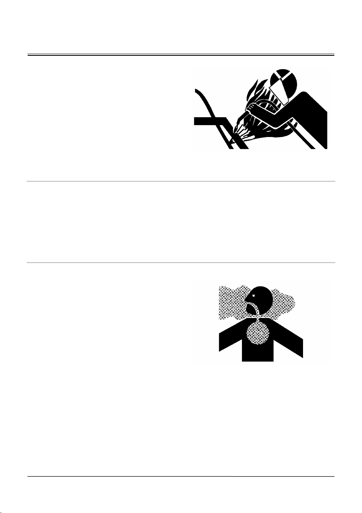
AVOID HEATING NEAR PRESSURIZED
FLUID LINES
• Flammable spray can be generated by heating near
pressurized fluid lines, resulting in severe burns to
yourself and bystanders.
• Do not heat by welding, soldering, or using a torch
near pressurized fluid lines or other flammable
materials.
• Pressurized lines can be accidentally cut when
heat goes beyond the immediate flame area. Install temporary fireresistant guards to protect
hoses or other materials before engaging in
welding, soldering, etc..
AVOID APPLYING HEAT TO LINES CONTAINING FLAMMABLE FLUIDS
• Do not weld or flame cut pipes or tubes that con-
tain flammable fluids.
• Clean them thoroughly with nonflammable solvent
before welding or flame cutting them.
510-E01B-0030
REMOVE PAINT BEFORE WELDING OR
HEATING
• Hazardous fumes can be generated when paint is
heated by welding, soldering, or using a torch. If
inhaled, these fumes may cause sickness.
• Avoid potentially toxic fumes and dust.
• Do all such work outside or in a well-ventilated
area. Dispose of paint and solvent properly.
• Remove paint before welding or heating:
1. If you sand or grind paint, avoid breathing the dust.
Wear an approved respirator.
SA-030
2. If you use solvent or paint stripper, remove stripper with soap and water before welding. Remove
solvent or paint stripper containers and other
flammable material from area. Allow fumes to
disperse at least 15 minutes before welding or
heating.
511-E01A-0029
SA-029
SA-27
Page 32
SAFETY
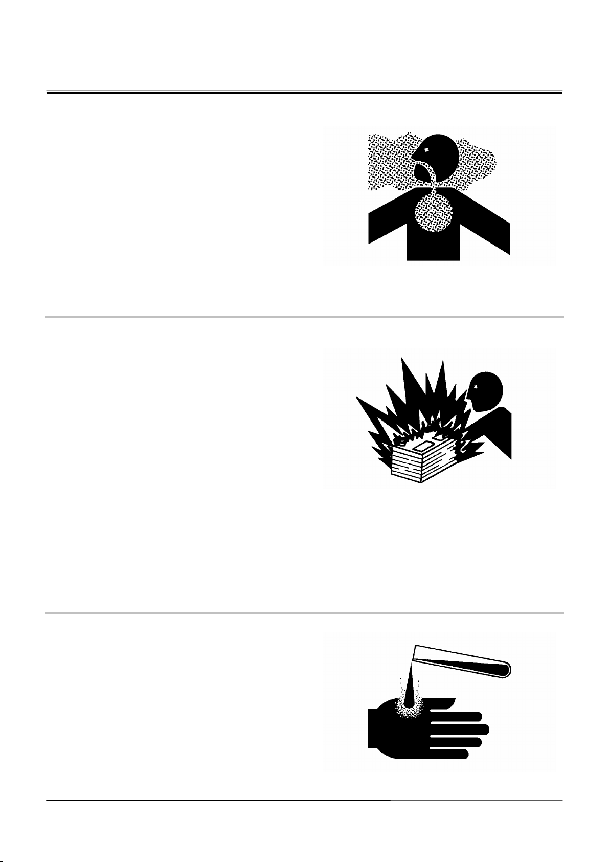
BEWARE OF ASBESTOS DUST
• Take care not to inhale dust produced in the work
site. Inhalation of asbestos fibers may be the cause
of lung cancer.
• Depending on the wok site conditions, the risk of
inhaling asbestos fiber may exist. Spray water to
prevent asbestos from becoming airborne. Do not
use compressed air.
• When operating the machine in a work site where
asbestos might be present, be sure to operate the
machine from the upwind side and wear a mask
rated to prevent the inhalation of asbestos.
• Keep bystanders out of the work site during op-
eration.
• Asbestos might be present in imitation parts. Use
only genuine Hitachi Parts.
PREVENT BATTERY EXPLOSIONS
• Battery gas can explode.
• Keep sparks, lighted matches, and flame away
from the top of battery.
• Never check battery charge by placing a metal
object across the posts. Use a voltmeter or hydrometer.
• Do not charge a frozen battery; it may explode.
Warm the battery to 16 °C (60 °F) first.
• Do not continue to use or charge the battery when
electrolyte level is lower than specified. Explosion
of the battery may result.
• Loose terminals may produce sparks. Securely
tighten all terminals.
• Battery electrolyte is poisonous. If the battery should
explode, battery electrolyte may be splashed into
eyes, possibly resulting in blindness.
• Be sure to wear eye protection when checking
electrolyte specific gravity.
512-E01B-0032
SERVICE AIR CONDITIONING SYSTEM
SAFELY
• If spilled onto skin, refrigerant may cause a cold
contact burn.
• Refer to the instructions described on the con-
tainer for proper use when handling the refrigerant.
• Use a recovery and recycling system to avoid
leaking refrigerant into the atmosphere.
• Never touch the refrigerant.
513-E01A-0405
SA-029
SA-032
SA-405
SA-28
Page 33
SAFETY
HANDLE CHEMICAL PRODUCTS SAFELY
• Direct exposure to hazardous chemicals can cause
serious injury. Potentially hazardous chemicals used
with your machine include such items as lubricants,
coolants, paints, and adhesives.
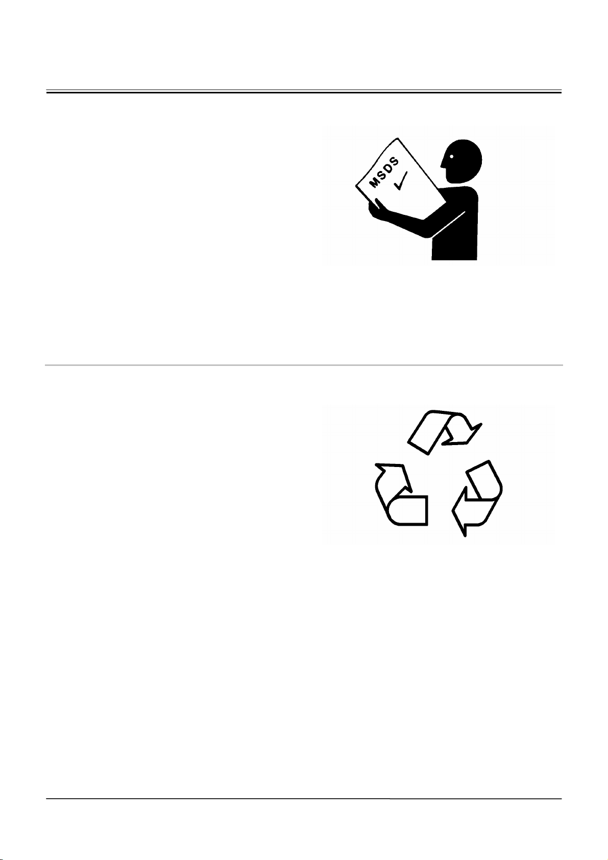
• A Material Safety Data Sheet (MSDS) provides
specific details on chemical products: physical
and health hazards, safety procedures, and
emergency response techniques.
• Check the MSDS before you start any job using a
hazardous chemical. That way you will know exactly what the risks are and how to do the job
safely. Then follow procedures and use recommended equipment.
• See your authorized dealer for MSDS’s (available
only in English) on chemical products used with
your machine.
515-E01A-0309
DISPOSE OF WASTE PROPERLY
• Improperly disposing of waste can threaten the en-
vironment and ecology. Potentially harmful waste
used with HITACHI equipment includes such items
as oil, fuel, coolant, brake fluid, filters, and batteries.
• Use leakproof containers when draining fluids. Do
not use food or beverage containers that may
mislead someone into drinking from them.
• Do not pour waste onto the ground, down a drain,
or into any water source.
• Air conditioning refrigerants escaping into the air
can
• damage the Earth’s atmosphere. Government
regulations may require a certified air conditioning
service center to recover and recycle used air
conditioning refrigerants.
• Inquire on the proper way to recycle or dispose of
waste from your local environmental or recycling
center, or from your authorized dealer.
516-E01A-0226
SA-309
SA-226
SA-29
Page 34
SAFETY
BEFORE RETURNING THE MACHINE TO
THE CUSTOMER
• After maintenance or repair work is complete,
confirm that:
• The machine is functioning properly, especially
the safety systems.
• Worn or damaged parts have been repaired or
replaced.
S517-E01A-0435
SA-435
SA-30
Page 35
SECTION AND GROUP
CONTENTS
WORKSHOP MANUAL
All information, illustrations and specifications in this manual are based on
the latest product information available
at the time of publication. The right is
reserved to make changes at any time
without notice.
SECTION 1 GENERAL
Group 1 Precautions for disassembling
and Assembling
Group 2 Tightening
Group 3 Painting
Group 4 Bleed Air from Hydraulic Oil Tank
SECTION 2 BODY (UPPERSTRUCTURE)
Group 1 Cab
Group 2 Counterweight
Group 3 Center Hinge
Group 4 Hood
Group 5 Hydraulic Oil Tank
Group 6 Pump Device
Group 7 Control Valve
Group 8 Pilot Valve
Group 9 Pilot Shut-Off Valve
Group 10 Hydraulic Fan Pump and Motor
SECTION 3 BODY (TRAVEL SYSTEM)
Group 1 Tire
Group 2 Drive Unit
Group 3 Axle
Group 4 Propeller Shaft
Group 5 Brake Valve
Group 6 Charging Block
Group 7 Steering Pilot Valve
Group 8 Steering Valve
Group 9 Steering Cylinder
COPYRIGHT(C)2007
Hitachi Construction Machinery Co., Ltd.
Tokyo, Japan
All rights reserved
SECTION 4 FRONT ATTACHMENT
Group 1 Front Attachment
Group 2 Cylinder
Page 36

Group 1 Specification
Group 2 Component Layout
Group 3 Component Specifications
SECTION 2 SYSTEM
Group 1 Control System
Group 2 ECM System
Group 3 Hydraulic System
Group 4 Electrical System
FORMANCE TEST
Group 1 Introduction
Group 2 Standard
Group 3 Engine Test
Group 4 Wheel Loader Test
Group 5 Component Test
Group 6 Adjustment
SECTION 3 COMPONENT OPERATION
Group 1 Pump Device
Group 2 Control Valve
Group 3 Hydraulic Fan Motor
Group 4 Steering Pilot Valve
Group 5 Steering Valve
Group 6 Pilot Valve
Group 7 Charging Block
Group 8 Ride Control Valve
Group 9 Drive Unit
Group 10 Axle
Group 11 Brake Valve
Group 12 Others
SECTION 5 TROUBLESHOOTING
Group 1 Diagnosing Procedure
Group 2 Dr. ZX
Group 3 e-Wheel
Group 4 Component Layout
Group 5 Troubleshooting A
Group 6 Troubleshooting B
Group 7 Troubleshooting C
Group 8 Electrical System Inspection
Page 37

⎯ CONTENTS ⎯
Group 1 Precautions for Disassembling
and Assembling
Precautions for Disassembling and
Assembling ............................................ W1-1-1
Maintenance Standard Terminology......... W1-1-7
Group 2 Tightening
Tightening Torque Specifications ............. W1-2-1
Torque Chart............................................ W1-2-2
Piping Joint.............................................. W1-2-5
Periodic Replacement Parts .................... W1-2-9
Group 3 Painting
Painting ................................................... W1-3-1
Group 4 Bleed Air from Hydraulic Oil Tank
Bleed Air from Hydraulic Oil Tank ............ W1-4-1
SECTION 1
GENERAL
4HAW-1-1
Page 38

(Blank)
4HAW-1-2
Page 39

GENERAL / Precautions for Disassembling and Assembling
PRECAUTIONS FOR DISASSEMBLING
AND ASSEMBLING
Precautions for Disassembling and Assembling
• Clean the Machine
Thoroughly wash the machine before bringing it into
the shop. Bringing a dirty machine into the shop
may cause machine components to be
contaminated during disassembling/assembling,
resulting in damage to machine components, as
well as decreased efficiency in service work.
• Inspect the Machine
Be sure to thoroughly understand all
disassem-bling/assembling procedures beforehand,
to help avoid incorrect disassembling of
components as well as personal injury.
Check and record the items listed below to prevent
problems from occurring in the future.
• The machine model, machine serial number, and
hour meter reading.
• Reason for disassembly (symptoms, failed parts,
and causes).
• Clogging of filters and oil, water or air leaks, if
any.
• Capacities and condition of lubricants.
• Loose or damaged parts.
• Prepare and Clean Tools and Disassembly Area
Prepare the necessary tools to be used and the
area for disassembling work.
• Precautions for Disassembling
• To prevent dirt from entering, cap or plug the
removed pipes.
• Before disassembling, clean the exterior of the
components and place on a work bench.
• Before disassembling, drain gear oil from the
reduction gear.
• Be sure to provide appropriate containers for
draining fluids.
• Use matching marks for easier reassembling.
• Be sure to use the specified special tools, when
instructed.
• If a part or component cannot be removed after
removing its securing nuts and bolts, do not
attempt to remove it forcibly. Find the cause(s),
then take the appropriate measures to remove it.
• Orderly arrange disassembled parts. Mark and
tag them as necessary.
• Store common parts, such as bolts and nuts with
reference to where they are to be used and in a
manner that will prevent loss.
• Inspect the contact or sliding surfaces of
disassembled parts for abnormal wear, sticking,
or other damage.
• Measure and record the degree of wear and
clearances.
W1-1-1
Page 40

GENERAL / Precautions for Disassembling and Assembling
• Precautions for Assembling
• Be sure to clean all parts and inspect them for
any damage. If any damage is found, repair or
replace part.
• Dirt or debris on the contact or sliding surfaces
may shorten the service life of the machine. Take
care not to contaminate any contact or sliding
surfaces.
• Be sure to replace O-rings, backup rings, and oil
seals with new ones once they are disassembled.
Apply a film of grease before installing.
• Be sure that liquid-gasket-applied surfaces are
clean and dry.
• If an anti-corrosive agent has been used on a
new part, be sure to thoroughly clean the part to
remove the agent.
• Utilize matching marks when assembling.
• Be sure to use the designated tools to assemble
bearings, bushings and oil seals.
• Keep a record of the number of tools used for
disassembly/assembly. After assembling is
complete, count the number of tools, so as to
make sure that no forgotten tools remain in the
assembled machine.
Bleeding Air from Hydraulic System
When hydraulic oil is drained, the suction filter or the
suction lines are replaced, or the removal and installation of the pump, swing motor, travel motor or
cylinder is done, bleed air from the hydraulic system
in the following procedures:
IMPORTANT: If the engine is started with air
trapped in the hydraulic pump housing, damage to the pump may result.
If the cylinder is operated with air
trapped in the cylinder tube, damage to the cylinder may result.
Be sure to bleed air before starting
the engine.
• Bleeding Air from Hydraulic Pump
• Remove the air bleeding plug from the top of the
pump and fill the pump housing with hydraulic oil.
• After the pump housing is filled with hydraulic oil,
temporarily tighten the plug. Then, start the engine and run at slow idle speed.
• Slightly loosen the plug to bleed air from the
pump housing until hydraulic oil oozes out.
• After bleeding all the air, securely tighten the
plug.
W1-1-2
Page 41

GENERAL / Precautions for Disassembling and Assembling
• Bleeding Air from Hydraulic Circuit
• After refilling hydraulic oil, start the engine. While
operating each cylinder, operate the machine
under light loads for 10 to 15 minutes. Slowly
start each operation (never fully stroke the cylinders during initial operation stage). As the pilot oil
circuit has an air bleed device, air trapped in the
pilot oil circuit will be bled while performing the
above operation for approx. 5 minutes.
• Reposition the front attachment to check hydraulic oil level.
• Stop the engine. Recheck hydraulic oil level. Replenish oil as necessary.
W4GB-01-01-001
W1-1-3
Page 42
GENERAL / Precautions for Disassembling and Assembling
A
Floating Seal Precautions
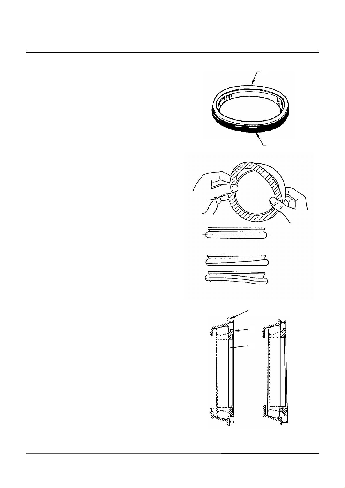
1. In general, replace the floating seal with a new
one after disassembling.
If the floating seal is to be reused, follow these
procedures:
(1) Keep seal rings together as a matched set
with seal ring faces together. Insert a piece of
cardboard to protect surfaces.
(2) Check sliding surface (C) on seal ring (A) for
scuffing, scoring, corrosion, deformation or
uneven wear.
(3) Check O-ring (B) for tears, breaks,
deformation or hardening.
2. If incorrectly assembled, oil leakage or damage
will occur. Be sure to do the following, to prevent
trouble.
(1) Clean the floating seal and seal mounting
bores with cleaning solvent.
Use a wire brush to remove mud, rust or dirt.
After cleaning, thoroughly dry parts with
compressed air.
(2) Clean the floating seal and seal mounting
bores. Check the bore surface for scuffing or
scoring by touching the surface with touch.
(3) Check that O-ring (B) is not twisted, and that it
is installed correctly on seal ring (A).
(4) After installing the floating seal, check that
seal ring surface (C) is parallel with seal
mating face (D) by measuring the distances
(C) and (D) at point (a) and (b), as illustrated.
If these distances differ, correct O-ring (B)
seating.
Incorrect
Correct
D
C
B
B
W105-03-05-019
Incorrect Correct
W105-03-05-020
aa
bb
a=b
a≠b
W110-03-05-004
W1-1-4
Page 43
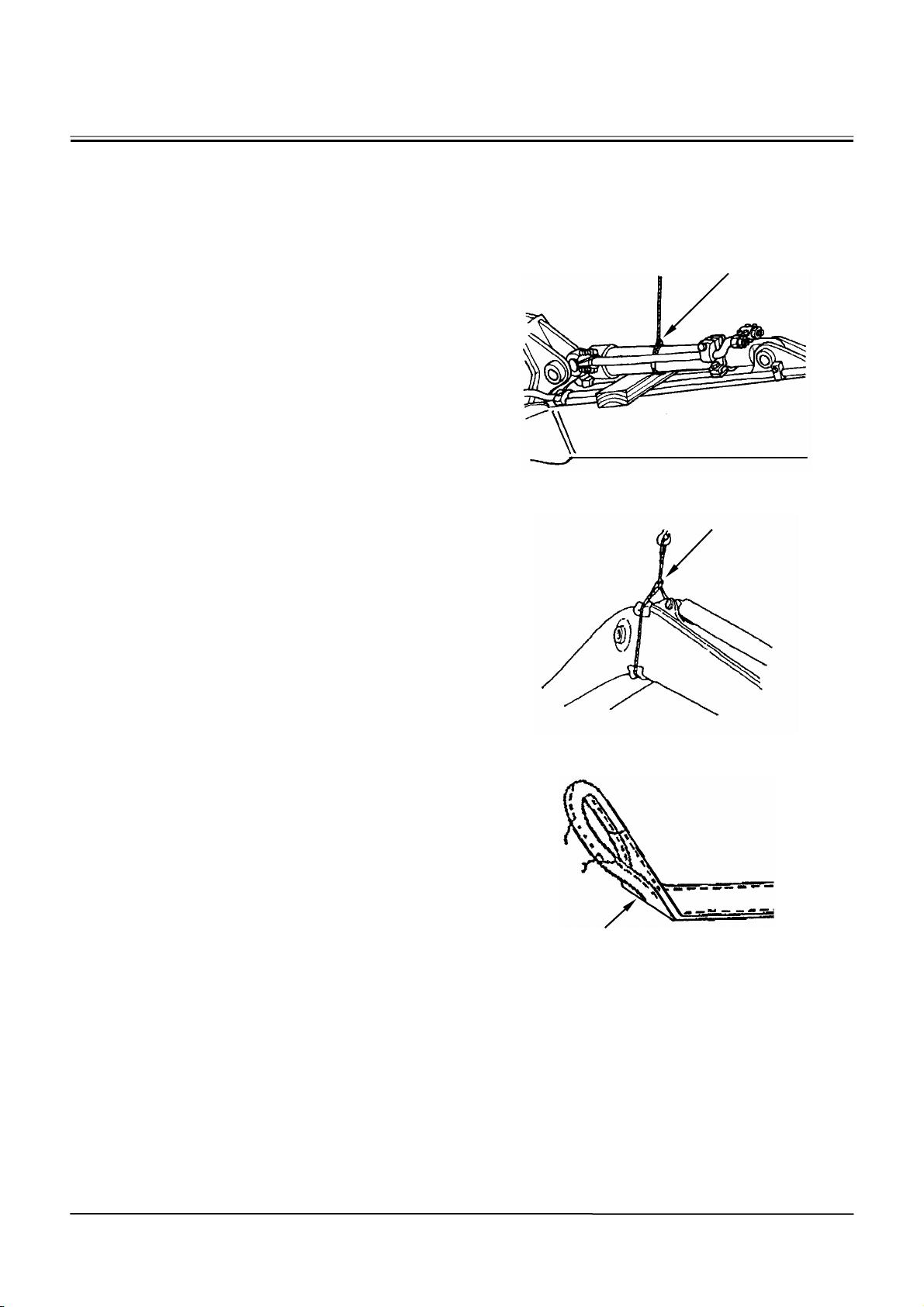
GENERAL / Precautions for Disassembling and Assembling
Precautions for Using Nylon Sling
1. Follow the precautions below to use nylon slings
safely.
• Attach protectors (soft material) on the corners of
the load so that the nylon sling does not directly
contact the corners. This will prevent the nylon
sling from being damaged and the lifted load from
slipping.
• Lower the temperature of the lifted load to lower
than 100 °C (212 °F). If unavoidably lifting a load
with a temperature of 100 °C (212 °F) or more,
reduce the load weight.
• Do not lift acid or alkali chemicals.
• Take care not to allow the sling to become wet.
The load may slip.
• When required to use more than one sling, use
slings with the same width and length to keep the
lifted load balanced.
• When lifting a load using an eyehole, be sure to
eliminate any gaps between the sling and load.
(Refer to the right illustration.) Reduce the load
weight so that it is less than 80 % of the sling
breaking force.
• Avoid using twisted, bound, connected, or
hitched slings.
• Do not place any object on twisted or bent slings.
(Refer to the right illustration.)
• When removing the slings from under the load,
take care not to damage the nylon slings. Avoid
contact with protrusions.
• Avoid dragging slings on the ground, throwing
slings or pushing slings with a metal object.
• When using with other types of slings (wire rope)
or accessories (shackle), protect the joint so that
the nylon sling is not damaged.
• Store the nylon slings indoors so they won’t deteriorate with heat, sun light, or chemicals.
Correct Eyehole
Lifting Method
W102-04-02-016
Incorrect Eyehole
Lifting Method
W105-04-01-008
Bent Sling
W162-01-01-009
W1-1-5
Page 44
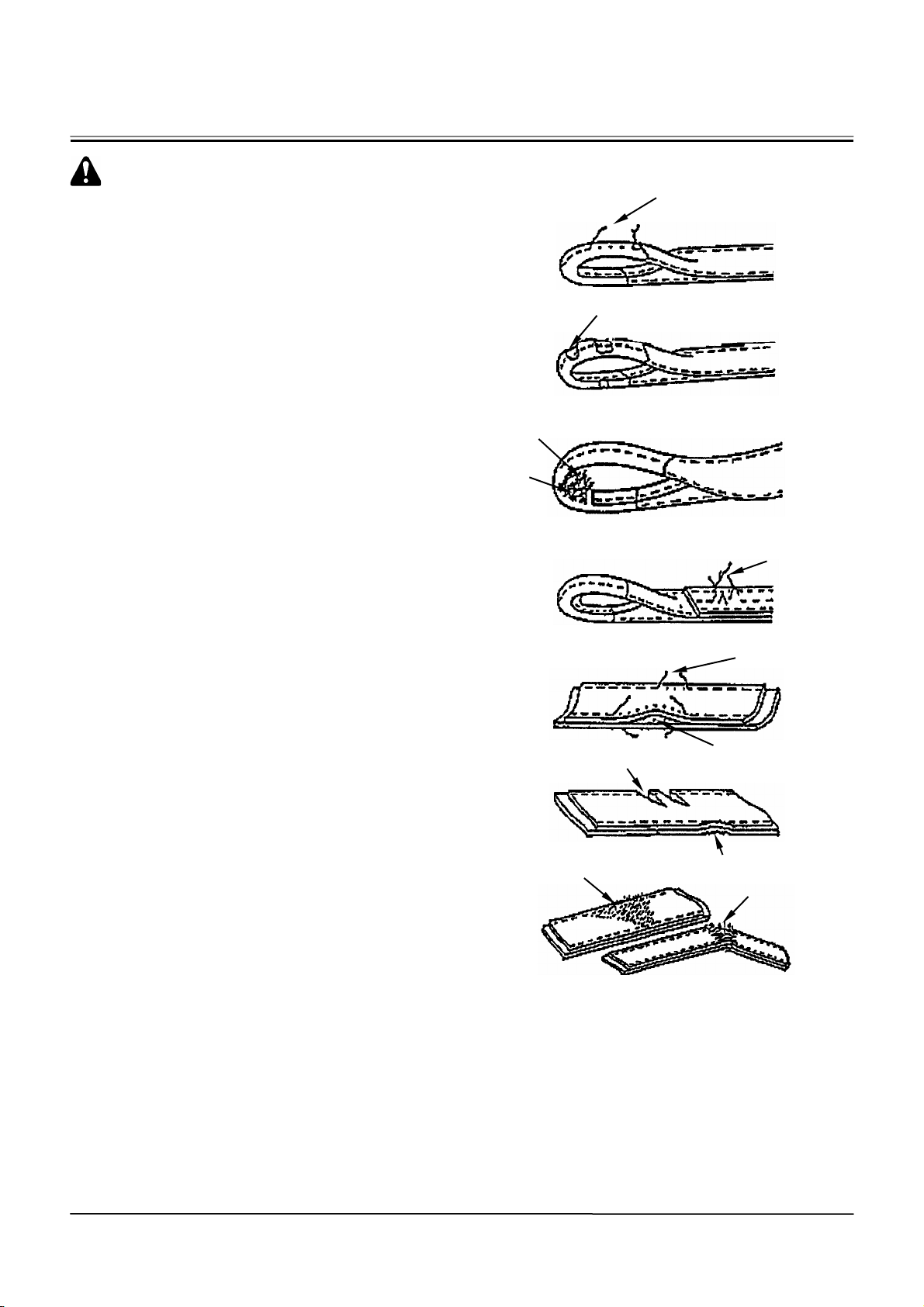
GENERAL / Precautions for Disassembling and Assembling
CAUTION: If a load is lifted with a damaged
nylon sling, serious personal injury may result. Be sure to visually check the nylon sling
for any damage before using.
2. Before using a nylon sling, visually check the nylon sling for any damage corresponding to examples shown to the right. If any damage is found,
cut and discard the sling. Even if no damage is
found, do not use slings older than 7-years.
Damaged Appearance
Fuzz
Broken Sewing
Thread
Scuffing
Broken Sewing Thread
W162-01-01-002
W162-01-01-003
W162-01-01-004
Broken Sewing
Thread
Broken Sewing
Thread
W162-01-01-005
Scoring
Separation of
Belt
W162-01-01-006
Fuzz
Scuffing
Broken Warp
W162-01-01-007
W162-01-01-008
W1-1-6
Page 45

GENERAL / Precautions for Disassembling and Assembling
MAINTENANCE STANDARD TERMINOLOGY
“Standard”
1. Dimension for parts on a new machine.
2. Dimension of new components or assemblies
adjusted to specification.
“Allowable Limit”
1. Normal machine performance cannot be accomplished after exceeding this limit.
2. Repair or adjustment is impossible after exceeding this limit.
3. Therefore, in consideration of operation efficiency
and maintenance expense, proper maintenance
shall be carried out before reaching the “Allowable Limit”.
W1-1-7
Page 46

(Blank)
GENERAL / Precautions for Disassembling and Assembling
W1-1-8
Page 47
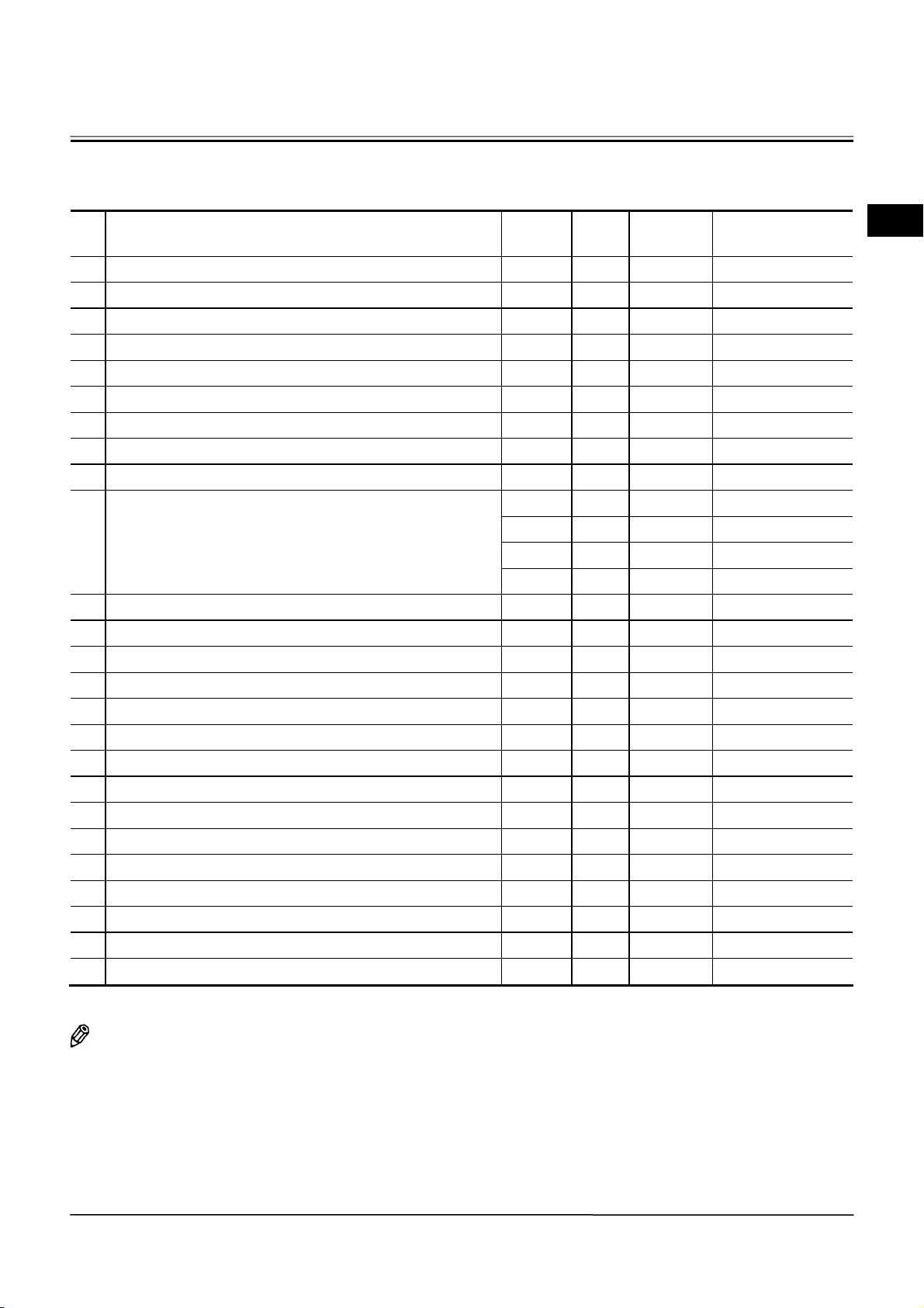
GENERAL / Tightening
TIGHTENING TORQUE SPECIFICATIONS
Bolts and Nuts of Machine: Standard Tightening Torque Chart
Descriptions Bolt Dia. Q’ty
Wrench
Size (mm)
1 Front axle mounting bolt 30 8 46 1579 (161)
2 Rear axle support mounting bolt 30 8 46 1579 (161)
3 Wheel rim mounting bolt 24 80 36 890 (91)
4 Propeller shaft mounting bolt 12 20 17 **143 (15)
5 Propeller shaft support bearing mounting bolt 20 2 30 206 (21)
6 Transmission mounting bolt; bracket 16 8 24 224 (23)
7 Transmission mounting bolt; cushion rubber 18 4 27 **315 (32)
8 Engine mounting bolt; bracket 14 8 22 180 (18)
9 Engine mounting bolt; cushion rubber 18 2 27 315 (32)
10 Muffler mounting bolt
12 4 17 34.2(3)
12 4 19 100 (10)
16 2 24 200 (20)
16 1 24 205 (21)
11 Counterweight mounting bolt 30 4 46 1510 (154)
12 Flange above upper center pin fixing 16 10 24 224 (23)
13 Lower center pin stopper 16 1 24 86.9 (9)
14 Loader front pin stopper 16 13 24 86.9 (9)
15 Steering cylinder pin stopper 16 4 24 86.9 (9)
16 Radiator frame mounting bolt 16 6 24 **154 (16)
17 Radiator mounting bolt 10 4 14 39 to 49 (4 to 5)
18 Intercooler mounting bolt 12 6 17 67 to 83 (7 to 8)
19 Oil cooler mounting bolt 10 8 14 39 to 49 (4 to 5)
20 Air conditioner condenser mounting bolt 8 4 12 12.5 (1)
21 Air conditioner compressor mounting bolt 8 4 12 23 to 30 (2 to 3)
22 Cab cushion rubber 16 4 24 **205 (21)
23 Bucket teeth mounting bolt (optional)
24 Cutting edge mounting bolt
25 Wear plate mounting bolt
*
11/4’ 16 46 1940 (198)
*
1’
*
1’ 8 37.47 1068(109)
12 37.47 1068 (109)
As for the bolt Dia. with mark *, the dimension is indicated in inch.
As for torque with mark **, LOCTITE #262 is used.
NOTE: When tightening, apply lubricant in order to reduce friction coefficient of bolts and nuts.
(Ex. white zinc B dissolved into spindle oil)
Remove rust, dirt and dust before installing fasteners.
Torque
N⋅m (kgf⋅m)
W1-2-1
Page 48
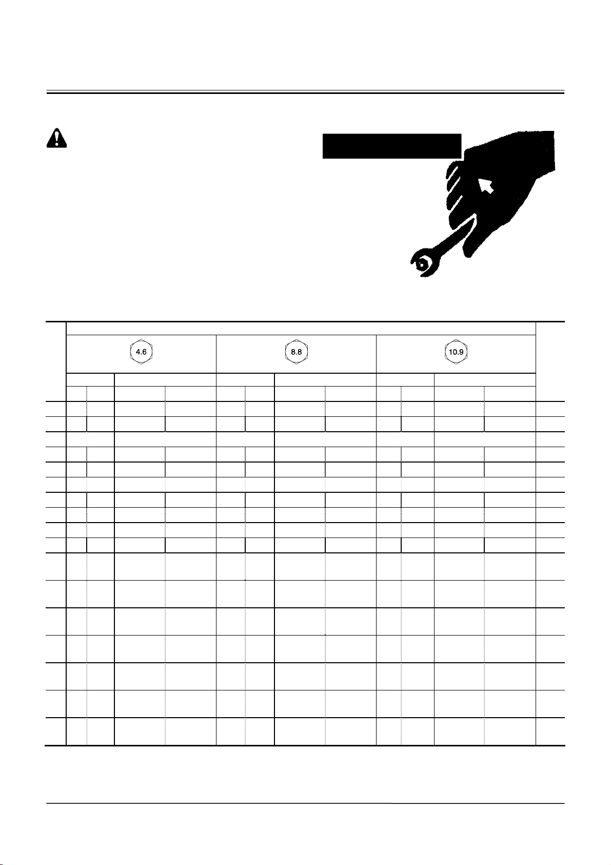
GENERAL / Tightening
TORQUE CHART
CAUTION: Use tools appropriate for the work
to be done. The make-do tools or parts are
dangerous. As the incorrect size tools are
slipped or removed, personal injury may be
caused.
Bolt Types
Tighten the nuts or bolts correctly to the torque
specifications.
As the different types and grades of bolt are used,
use and tighten the correct bolts correctly when assembling the machine or components.
Specified Tightening Torque
Hexagon Wrench
Bolt
Dia.
(mm)
Target Va l u e Allowable Value Ta r g e t Va l u e Allowable Value Tar ge t Va l u e Allowable Value
N⋅m kgf⋅cm N⋅ m kgf⋅cm N⋅m kgf⋅cm N⋅m kgf⋅cm N⋅mkgf⋅cm N⋅m kgf⋅ cm
4 1.15 11.7 0.92 to 1.38 9.4 to 14.1 3.06 31.2 2.45 to 3.67 25.0 to 37.4 4.49 45.8 3.60 to 5.39 36.7 to 55.0 7
5 2.36 24.1 1.89 to 2.82 19.3 to 28.8 6.30 64.2 5.03 to 7.55 51.3 to 77.0 9.24 94.2 7.40 to 11.1 75.5 to 113 8
6 4.98 40.6 3.20 to 4.79 32.6 to 48.8 10.6 108 8.50 to 12.7 86.7 to 130 15.6 159 12.6 to 18.7 128 to 191 10
8 9.81 100 7.84 to 11.7 79.9 to 119 26.1 266 20.9 to 31.0 213 to 319 38.3 391 30.7 to 46.0 313 to 469 13
10 19.5 199 15.6 to 23.4 159 to 239 52.1 531 41.6 to 62.5 424 to 638 76.5 780 61.2 to 91.8 624 to 936 17
12 34.2 349 27.5 to 41.1 280 to 419 91.2 930 73.1 to 109 745 to 1110 133 1360 108 to 161 1100 to 1640 19
14 55.0 561 43.9 to65.9 448 to 672 146 1490 117 to 177 1190 to 1800 216 2200 173 to 258 1760 to 2630 22
16 86.9 886 69.5 to 104 709 to 1060 232 2370 185 to 279 1890 to 2840 341 3480 272 to 409 2770 to 4170 24
18 118 1200 94.6 to 142 965 to 1450 315 3210 252 to 379 2570 to 3860 463 4720 370 to 555 3770 to 5660 27
20 171 1740 136 to204 1390 to 2080 452 4610 362 to 543 3690 to 5540 665 6780 534 to 797 5440 to 8130 30
22 234 2390 187 to252 1910 to 2570 624 6360 499 to 749 5090 to 7640 918 9360 734 to 1100 7480 to
24 293 2990 234 to 352 2390 to 3590 782 7970 626 to 938 6380 to 9560 1150 11700 919 to 1380 9370 to
27 436 4450 349 to 524 3560 to 5340 1160 11800 931 to 1400 9490 to
30 588 6000 471 to 706 4800 to 7200 1570 16000 1260 to 1880
33 810 8260 648 to 972 6610 to 9910 2160 22000 1730 to 2590
36 1030 10500 828 to 1250
39 1350 13800 1080 to 1140
M4GB-07-121
8440 to 12700
11000 to 11650
2770 28200 2210 to 3310
3600 36700 2880 to 4320
M4GB-07-122
14300
12800 to
19200
17600 to
26400
22500 to
33800
29400 to
44100
1720 17500 1370 to
2300 23500 1840 to 2770
3170 32300 2540 to
4060 41400 3240 to
5290 53900 4240 to
2050
3810
4860
6350
14000 to 20900
18800 to 28200
25900 to 38800
33000 to 49600
43200 to 64800
M4GB-07-123
11200
14100
Wrench
SA-040
Size
mm
32
36
41
46
50
55
60
W1-2-2
Page 49
GENERAL / Tightening
Specified Tightening Torque
Bolt
Dia.
(mm)
Target Va l u e Allowable Value
N⋅m kgf⋅cm N⋅m kgf⋅cm
4 4.49 45.8 3.60 to 5.39 36.7 to 55.0 3
5 9.24 94.2 7.40 to 11.1 75.5 to 113 4
6 15.6 159 12.6 to 18.7 128 to 191 5
8 38.3 391 30.7 to 46.0 313 to 469 6
10 76.5 780 61.2 to 91.8 624 to 936 8
12 133 1360 108 to 161 1100 to 1640 10
14 216 2200 173 to 258 1760 to 2630 12
16 341 3480 272 to 409 2770 to 4170 14
18 463 4720 370 to 555 3770 to 5660 14
20 665 6780 534 to 797 5440 to 8130 17
22 918 9360 734 to 1100 7480 to 11200 17
24 1150 11700 919 to 1380 9370 to 14100 19
27 1720 17500 1370 to 2050 14000 to 20900 19
30 2300 23500 1840 to 2770 18800 to 28200 22
33 3170 32300 2540 to 3810 25900 to 38800 24
36 4060 41400 3240 to 4860 33000 to 49600 27
39 5290 53900 4240 to 6350 43200 to 64800 27
Socket Bolt
Wrench
Size
(mm)
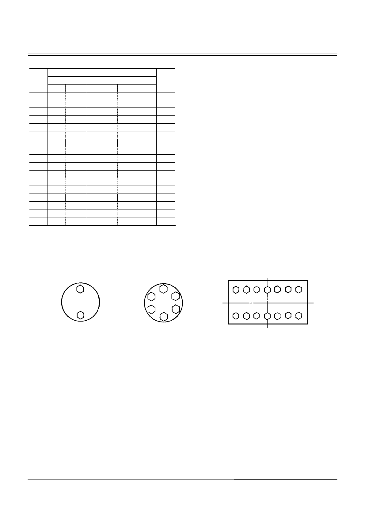
Tightening Order
When tightening two or more bolts, tighten them alternately, as shown, to ensure even tightening.
Equally tighten upper
and lower alternately
IMPORTANT: The following items are applied to
both fine and coarse pitch threads.
1. When tightening, apply lubricant in
order to reduce friction coefficient
of bolts and nuts. (Ex. white zinc B
dissolved into spindle oil)
2. Torque tolerance is ±20 %.
3. Use the bolts of correct length. The
bolts that are too long cannot be
tightened as the bolt tip comes into
contact with the bottom of bolt hole.
The bolts that are too short cannot
develop sufficient tightening force.
4. The torques given in table on the
previous page are for general use
only. Do not use these torques if a
different torque is given for a specific application.
5. Clean the nut and bolt threads and
remove dirt or corrosion before installing.
Tighten from center and diagonally Tighten diagonally
1.4
2.3
1
6
45
3
2
1
4
9
12 14
5
8
13
6 7
2 3
10 11
W105-01-01-003
W1-2-3
Page 50
GENERAL / Tightening
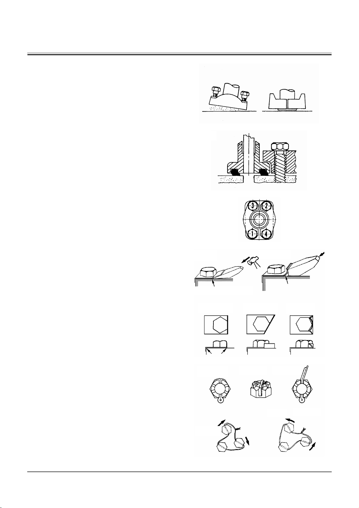
Precautions for Spilt Flange
IMPORTANT: 1. Clean the sealing surfaces. Check
if the scratches / roughness that
cause leaks and damage of O-ring
are found.
2. Use only specified O-rings. Inspect O-rings for any damage. Do
not file the O-ring surfaces. When
installing O-ring into a groove,
use grease in order to hold O-ring
in place.
3. While tightening the bolt by hand,
check that flange is installed to
the port correctly. Do not pinch
the O-ring.
4. Tighten the bolts alternately and
diagonally, in order to ensure
even tightening to the specified
torque.
5. Do not use air wrenches. Using an
air wrench often causes tightening of one bolt fully before tighten
the others, resulting in damage to
O-rings or uneven tightening of
bolts.
Nut and Bolt Locking
WRONG
RIGHT
W105-01-01-015
W105-01-01-016
W105-01-01-008
WRONG
• Lock Plate
IMPORTANT: Do not reuse the lock plates. Do not
try to bend the same point twice.
• Split Pin
IMPORTANT: Do not align the holes in the bolt and
nut while loosening. Tighten and
align anytime. Do not reuse the cotter pins.
• Wire
IMPORTANT: Attach a wire to bolts in the
bolt-tightening direction. Do not reuse the wire.
Bend along edge sharply
Bend along edge sharply
RIGHT RIGHT
RIGHT
Tighten
Do not bend it round
RIGHT RIGHT
WRONG
W105-01-01-009
WRONG
Loosen
WRONG
W1-2-4
W105-01-01-010
Page 51
GENERAL / Tightening
PIPING JOINT
IMPORTANT: The torques given in the chart below
are for general use only.
Do not use these torques if a different torque is given for a specific application.
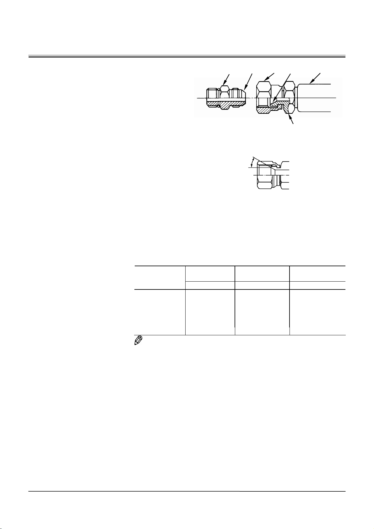
Union Joint
Metal sealing surfaces (4) and (5) of adapter (1) and
hose (2) fit together to seal pressure oil. Union joints
are used to join small-diameter lines.
IMPORTANT: 1. Do not over-tighten nut (3). Ex-
cessive force will be applied to
metal sealing surfaces (4) and (5),
possibly cracking adapter (1). Be
sure to tighten nut (3) to specifications.
2. Scratches or other damage to
sealing surfaces (4) or (5) will
cause oil leakage at the joint.
Take care not to damage them
when connecting/disconnecting.
Description
37°female 17 14 24.5 (2.5, 18)
19 17 29.5 (3.0, 21.5)
22 19 39 (4.0, 28.5)
27 22 93 (9.5, 69)
32 27 137 (14.0, 101)
36 32 175 (18.0, 129)
NOTE: Tightening torque of 37
to tightening torque of 37
1
4
3
Joint Body
5
2
M202-07-051
37°
Female Union Joint
W4GB-01-02-001
Wrench Size
mm
Wrench Size
mm
Tightening Torque
Union Nut Joint Body N⋅m (kgf⋅m, lbf⋅ft)
°
male coupling without union is similar
°
female.
W1-2-5
Page 52
GENERAL / Tightening
O-ring Seal Joint
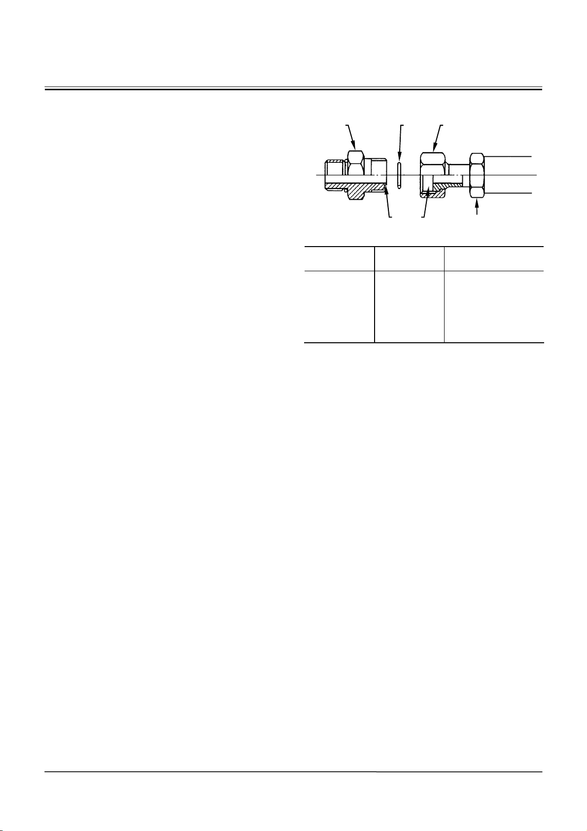
O-ring (6) is installed against the end face of adapter
(7) and seals pressure oil.
IMPORTANT: 1. Replace O-ring (6) with a new one
when reinstalling.
2. Before tightening union nut (9),
confirm that O-ring (6) is seated
correctly in O-ring groove (8).
Tightening union nut (9) with
O-ring (6) displaced will damage
O-ring (6), resulting in oil leakage.
3. Do not damage O-ring groove (8)
or sealing surface (10) in adapter
(7). Damage to O-ring (6) may
cause oil leakage.
4. If union nut (9) is found to be
loose, causing oil leakage, do not
tighten it to stop the leak. Instead,
replace O-ring (6) with a new one,
then tighten union nut (9) after
confirming that O-ring (6) is securely seated in place.
7 6 9
8 10
Joint Body
Wrench Size
mm
Wrench Size
mm
Tightening Torque
Union Nut Joint Body N⋅m (kgf⋅m, lbf⋅ft)
27 22 93 (9.5, 69)
32 27 137 (14.0, 101)
36 30,32 175 (18.0, 129)
41 36 205 (21.0, 151)
50 46 330 (33.7, 243)
M104-07-033
W1-2-6
Page 53
GENERAL / Tightening
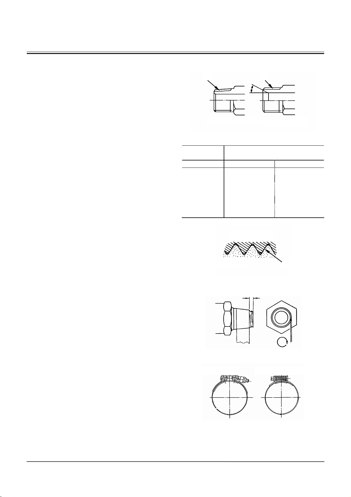
Screw-In Connection
Depending on types of screw and sealing, different
types of screw-in connection are used.
IMPORTANT: Check that the thread pitch and
thread type (tapered or straight) are
the correct type before using any
screw-in connection.
(In general, the screw-in connection
of male tapered thread is used except when measuring.))
Seal Tape Application
Seal tape is used in order to seal clearances between male and female threads so that any leaks
between threads may be prevented. Apply just
enough seal tape to fill up thread clearances. Do not
overwrap.
• Application Procedure
Check that the thread surface is clean and, free of
dirt or damage. Apply the seal tape around threads
in order to leave one to two pitch threads uncovered.
Wrap the seal tape in the same direction as the
threads.
Low-Pressure-Hose Clamp Tightening
Low-pressure-hose clamp tightening torque differs
depending on the type of clamp.
T-Bolt Type Band Clamp:
4.4 N⋅m (0.45 kgf⋅m, 3.25 lbf⋅ft )
Worm Gear Type Band Clamp:
5.9 to 6.9 N⋅m (0.6 to 0.7 kg⋅m, 4.3 to 5.1 lbf⋅ft)
PT
30°
PF
Male Straight Thread Male Tapered Thread
Wrench Size
mm
Tightening Torque
N⋅m (kgf⋅m, lbf⋅ft)
Joint Body FC material SS material
19 14.5 (1.5,10.5) 34 (3.5,25)
22 29.5 (3.0,21.5) 49 (5.0,36)
27 49 (5.0,36) 93 (9.5,69)
36 69 (7.0,51) 157 (16,116)
41 108 (11,80) 205 (21,151)
50 157 (16,116) 320 (33,235)
60 195 (20,144)
Internal Thread
External Thread
Clearance
Leave one to two pitch threads uncovered
W105-01-01-018
W105-01-01-019
M114-07-041
W1-2-7
T-Bolt Type Band Clamp Worm Gear Type Band Clamp
M114-07-043 M114-07-042
Page 54
GENERAL / Tightening
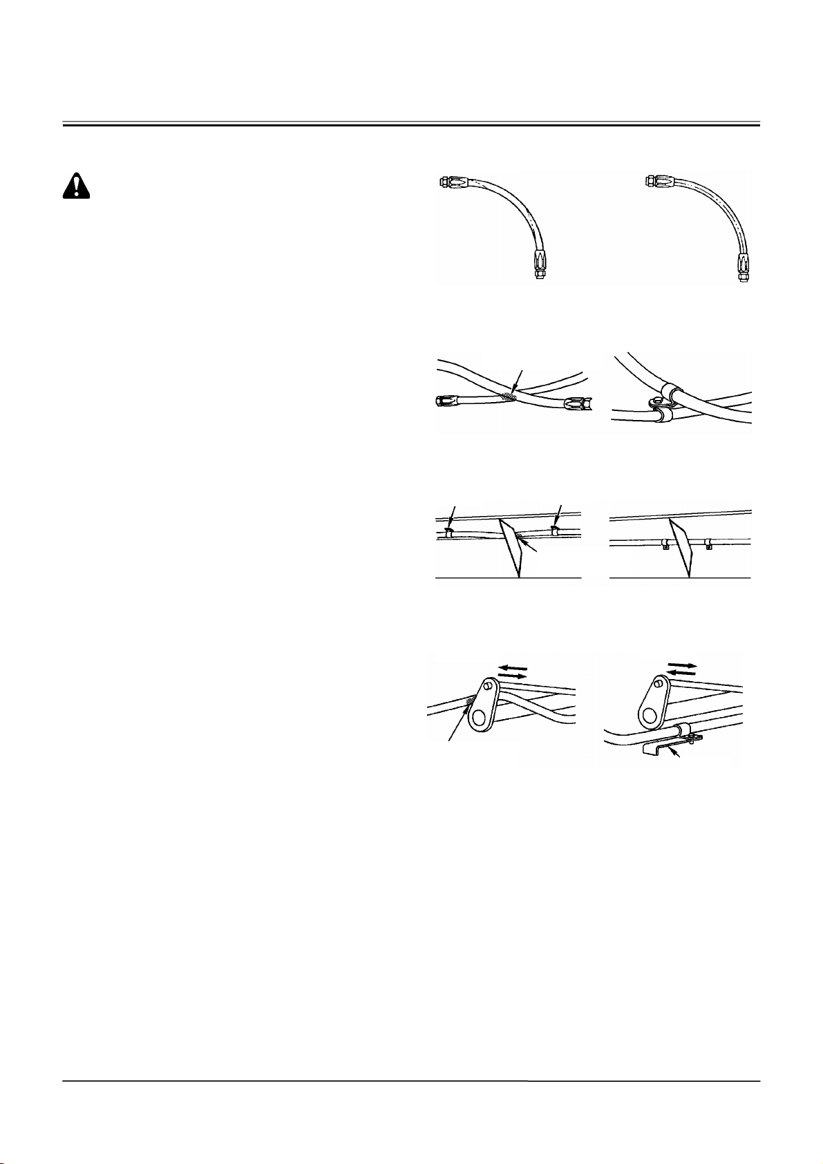
Connecting Hose
CAUTION: When replacing the hoses, use
only genuine Hitachi service parts. Using
hoses other than genuine Hitachi hoses may
cause oil leaks, hose rupture or separation of
fitting, possibly resulting in a fire on the
machine.
Do not install hoses kinked. Application of
high oil pressure, vibration, or an impact to a
kinked hose may result in oil leaks, hose
rupture or separation of fitting. Utilize the
print marks on hoses when installing in order
to prevent hose from being kinked.
Take necessary measures to protect hoses
from rubbing against each other. If the hoses
rub against each other, wear to the hoses
may result and lead to hose rupture.
Take care so that the hoses do not come into
contact with the moving parts or sharp objects.
WRONG
Clamp
WRONG
Rubbing Against
Each Other
Clamp
Rubbing Against
Each Other
RIGHT
RIGHT WRONG
RIGHT WRONG
RIGHT
W105-01-01-011
W105-01-01-012
W105-01-01-013
Rubbing Against
Each Other
W1-2-8
Clamp
W105-01-01-014
Page 55
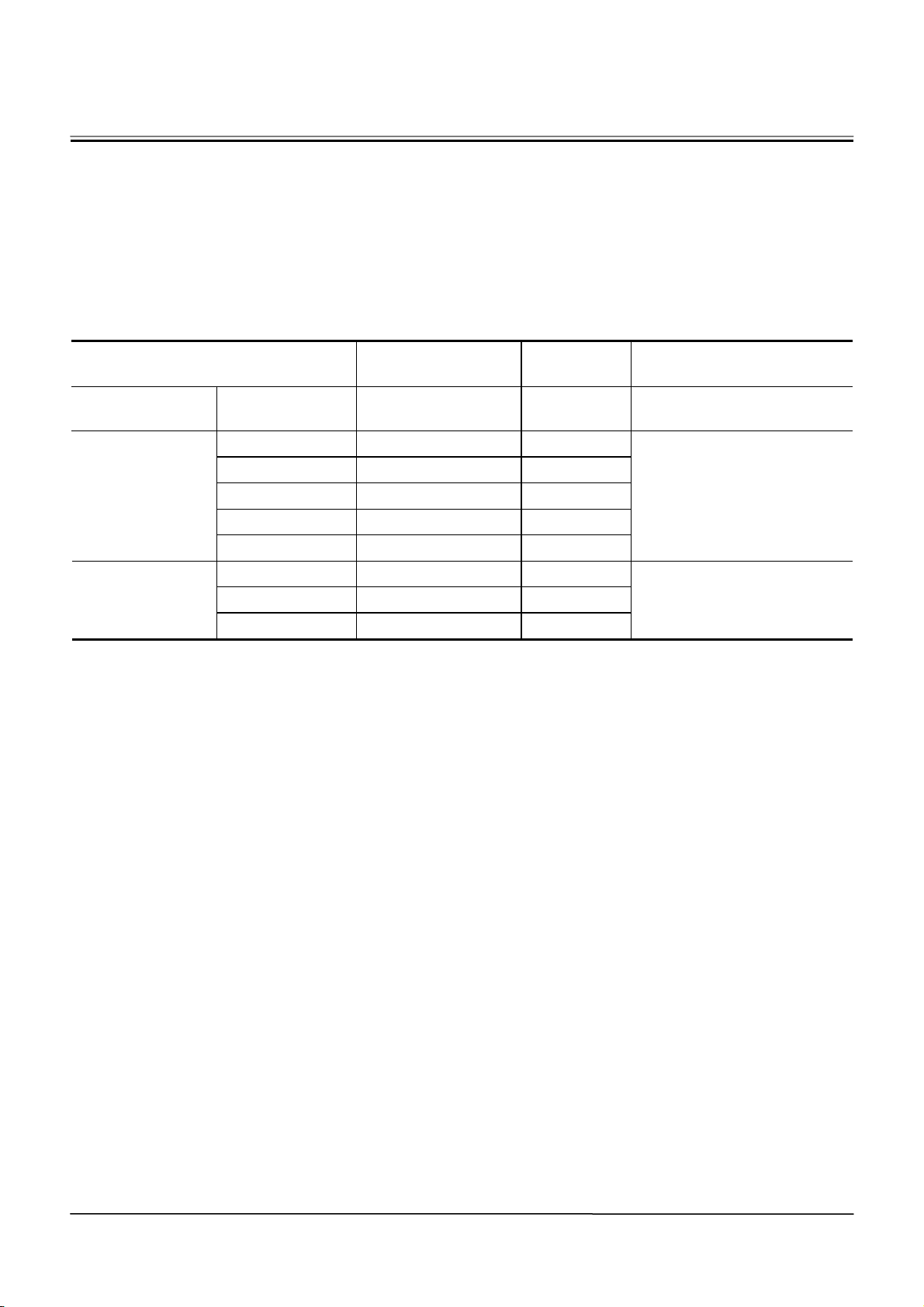
GENERAL / Tightening
PERIODIC REPLACEMENT PARTS
1. Periodic Replacement Parts (1) (Safety Inspection Object)
In order to ensure safe operation, the users must
conduct daily checking before starting operation and
periodic inspection of the machine by law.
In order to ensure safe operation, conduct periodic
replacement of the security parts below.
Engine Fuel tank Hose Every 2 years
Brake valve Seals (rubber) Every 1 year
Wet-type brake D-ring in piston Every 4 years
Brake system
Steering system
1. Theses parts deteriorate, fatigue and weaken with
time. As it is very difficult to gauge extent of the
damaged parts according to periodic inspection,
replace them with the new ones regardless of
defect in the interval.
2. If any of these parts are found to be defective
regardless of the interval, repair or replace these
parts.
Brake pipe Hose Every 2 years
Stop Lamp Switch Every 2 years
Accumulator Accumulator (3 used) Every 2 years
Steering pipe Hose Every 2 years
Steering cylinder Seals (rubber) Every 4 years
Steering valve Seals (rubber) Every 2 years
Replacement Parts
Name
Replacement
Intervals
Replacement Cause
Fire breaking may occur because of fuel leakage.
If oil leakage occurs when
traveling, the machine cannot
be controlled.
If oil leakage occurs, the
steering cannot be controlled.
W1-2-9
Page 56
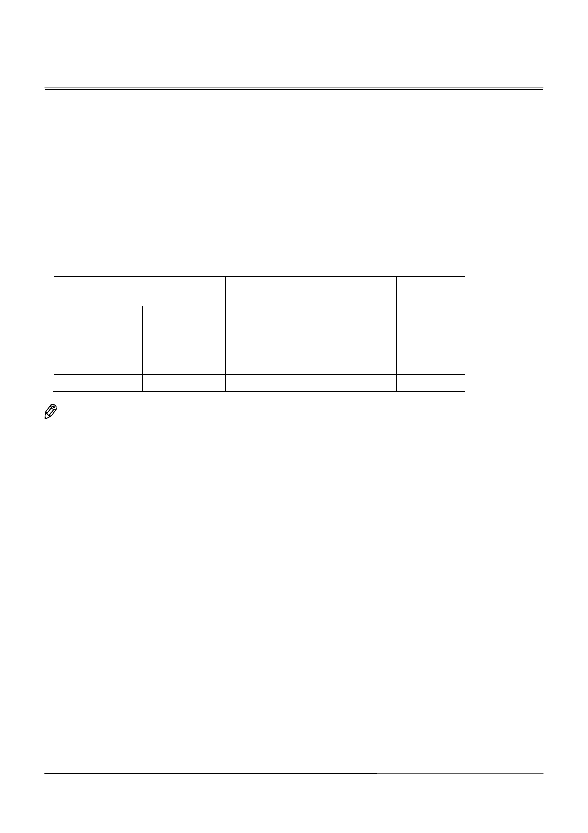
GENERAL / Tightening
2. Periodic Replacement Parts (2)
In order to ensure safe operation, conduct periodic
inspection of the machine.In order to ensure safe
operation further, conduct periodic replacement of
the parts below specially related to safety.
Theses parts deteriorate, fatigue and weaken with
time. This may cause serious personal/impersonal
hazard. As it is very difficult to gauge remnant life of
these parts according to driving sensation or
appearance inspection, replace them with the new
ones regardless of defect in the interval.
If any of these parts are found to be defective
according to periodic inspection regardless of the
interval, replace these parts
Replacement Parts Name
Pump
Hydraulic system
Working system
Driver’s seat Seat belt Seat belt Every 3 years
NOTE: Replace O-rings and the gaskets when
replacing the hoses.
Suction hose
Delivery hose
Bucket cylinder hose
Pilot hose
Lift arm cylinder line hose
Replacement
Intervals
Every 2 years
Every 2 years
W1-2-10
Page 57
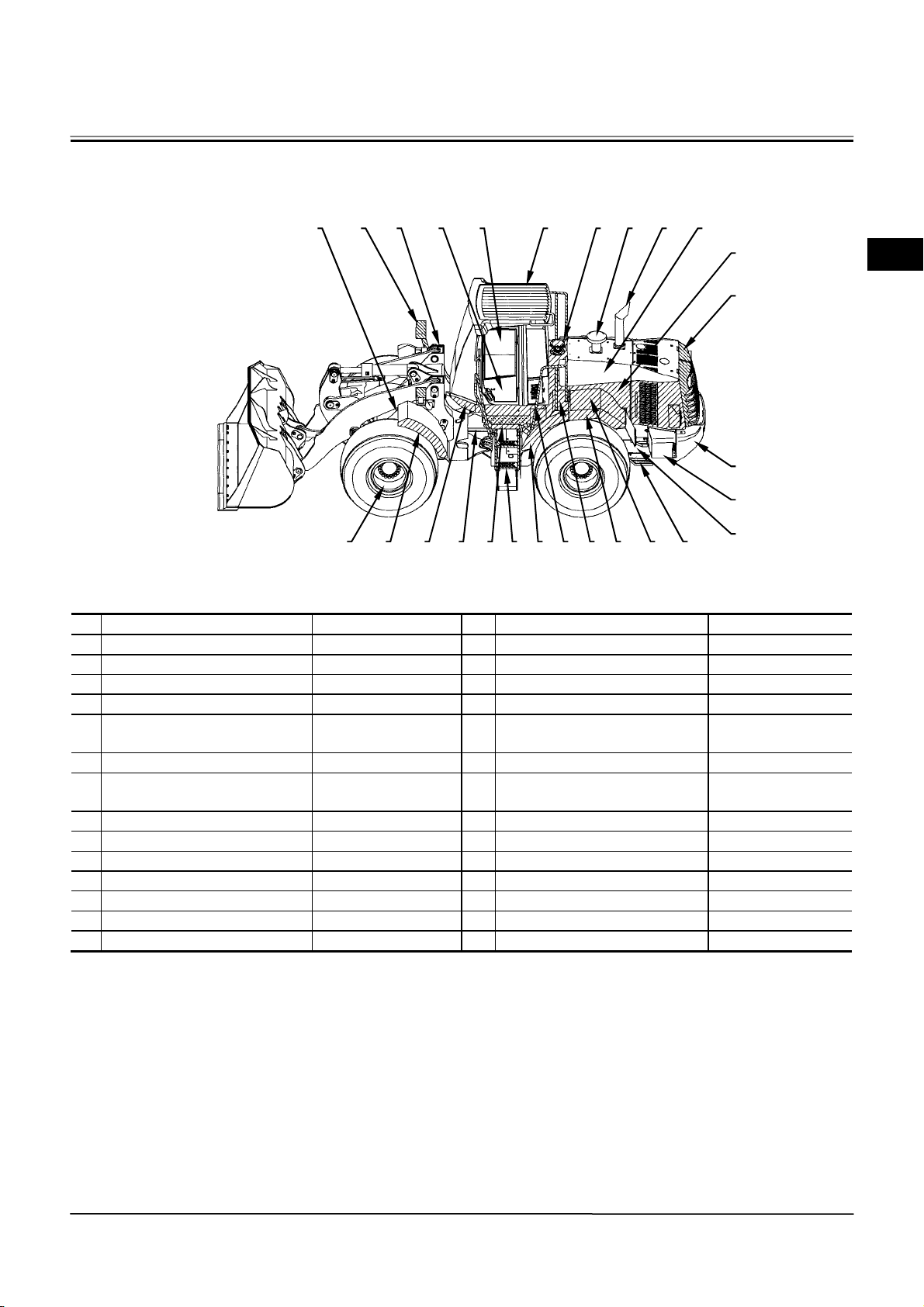
GENERAL / Painting
PAINTING
Surfaces to Be Painted Painting Colour Surfaces to Be Painted Painting Colour
1 Body TAXI Yellow 15 Rear Grill Not painted
2 Deck Plate HG Beige Deep 16 Counterweight TAXI Yellow
3 Handrail Warm Gray 17 Battery Box TAXI Yellow
4 Front Fender TAXI Yellow 18 Cockpit Skirt HG Beige Deep
Fender Cover Not painted
5
6 Lamp Bracket Warm Gray 20 Outside of Cab HG Beige Deep
Step Warm Gray
7
8 Rear Step TAXI Yellow 22 Articulate lock Bar Red
9 Rear Fender HG Beige Deep 23 Rim TAXI Yellow
10 Full Fender HG Beige Deep 24 Tail Pipe Not painted
11 Fuel Tank TAXI Yellow 25 Pre-Cleaner Not painted
12 Oil Tank HG Beige Deep
13 Side Cover TAXI Yellow
14 Lower Cover HG Beige Deep
IMPORTANT: When cleaning around front
attachment or cylinder, etc. fitted
with HN bushing, do not pour
washing liquid directly on the
bushing.
The ambient temperature should not
exceed 70 °C (158 °F) when painting
and drying.
4 6 1 19 21 20 12 25 24 13
8 10 59357222185 23
Cockpit and mounting parts
19
(Valve control box and so on)
Inside and Outside Surface of
21
Cab
HG Beige Deep
HG Beige Deep
14
15
16
17
11
W4GB-01-03-001
W1-3-1
Page 58

(Blank)
GENERAL / Painting
W1-3-2
Page 59
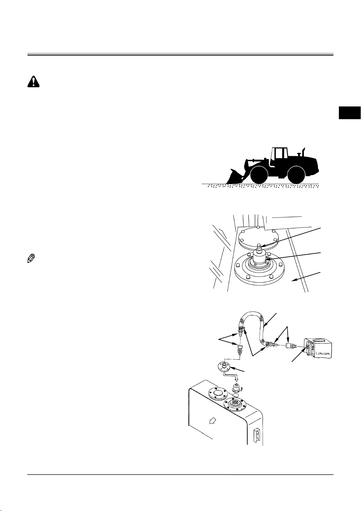
GENERAL / Bleed Air From Hydraulic Oil Tank
BLEED AIR FROM HYDRAULIC OIL TANK
CAUTION: Escaping fluid under pressure
may penetrate the skin and eyes, and cause
serious injury. Release the pressure before
removing hydraulic or other lines.
Hot hydraulic oil just after operation may
spout and cause severe burns. Wait for oil in
order to cool before starting any work.
Do not turn the cap on hydraulic oil tank
quickly. The cap may fly off by internal
pressure. Release any remaining pressure
and remove the cap.
Preparation
1. Park the machine on a solid, level surface. Lower
the front attachment onto the ground.
2. Stop the engine. Push valve (1) on hydraulic oil
tank (3) and release any remaining pressure.
3. Remove cap (2) on hydraulic oil tank (3).
4. Install a vacuum pump to the hole without cap (2).
Operate the vacuum pump and maintain negative
pressure in hydraulic oil tank (3).
NOTE: Run the vacuum pump continuously while
working.
W4GB-01-01-001
1
2
3
Coupler
Hydraulic oil
tank
Front
Clamp
Cover
Vacuum Hose
Coupler
Inlet
W4GB-01-01-002
Vacuum
Pump
W4GB-01-04-001
W1-4-1
Page 60

(Blank)
GENERAL / Bleed Air From Hydraulic Oil Tank
W1-4-2
Page 61

MEMO
........................................................................................................................................................................
........................................................................................................................................................................
........................................................................................................................................................................
........................................................................................................................................................................
........................................................................................................................................................................
........................................................................................................................................................................
........................................................................................................................................................................
........................................................................................................................................................................
........................................................................................................................................................................
........................................................................................................................................................................
........................................................................................................................................................................
........................................................................................................................................................................
........................................................................................................................................................................
........................................................................................................................................................................
........................................................................................................................................................................
........................................................................................................................................................................
........................................................................................................................................................................
........................................................................................................................................................................
........................................................................................................................................................................
........................................................................................................................................................................
........................................................................................................................................................................
........................................................................................................................................................................
........................................................................................................................................................................
........................................................................................................................................................................
........................................................................................................................................................................
........................................................................................................................................................................
........................................................................................................................................................................
........................................................................................................................................................................
........................................................................................................................................................................
........................................................................................................................................................................
Page 62

MEMO
........................................................................................................................................................................
........................................................................................................................................................................
........................................................................................................................................................................
........................................................................................................................................................................
........................................................................................................................................................................
........................................................................................................................................................................
........................................................................................................................................................................
........................................................................................................................................................................
........................................................................................................................................................................
........................................................................................................................................................................
........................................................................................................................................................................
........................................................................................................................................................................
........................................................................................................................................................................
........................................................................................................................................................................
........................................................................................................................................................................
........................................................................................................................................................................
........................................................................................................................................................................
........................................................................................................................................................................
........................................................................................................................................................................
........................................................................................................................................................................
........................................................................................................................................................................
........................................................................................................................................................................
........................................................................................................................................................................
........................................................................................................................................................................
........................................................................................................................................................................
........................................................................................................................................................................
........................................................................................................................................................................
........................................................................................................................................................................
........................................................................................................................................................................
........................................................................................................................................................................
Page 63

SECTION 2
BODY (UPPERSTRUCTURE)
— CONTENTS —
Group 1 Cab
Removal and Installation of Cab................. W2-1-1
Group 2 Counterweight
Removal and Installation of
Counterweight ........................................... W2-2-1
Group 3 Center Hinge
Disassembly of Center Hinge ..................... W2-3-1
Assembly of Center Hinge .......................... W2-3-6
Group 4 Hood
Removal and Installation of Hood............... W2-4-1
Group 5 Hydraulic Oil Tank
Removal and Installation of
Hydraulic Oil Tank ..................................... W2-5-1
Group 6 Pump Device
Removal and Installation of
Pump Device............................................. W2-6-1
Removal and Installation of
Pilot Pump and Regulator ......................... W2-6-8
Disassembly of Main Pump ...................... W2-6-12
Assembly of Main Pump ........................... W2-6-14
Disassembly of Regulator ......................... W2-6-20
Assembly of Regulator.............................. W2-6-22
Disassembly of Priority Valve.................... W2-6-24
Assembly of Priority Valve ........................ W2-6-26
Structure of Pilot Pump ............................. W2-6-28
Maintenance Standard.............................. W2-6-30
Group 7 Control Valve
Removal and Installation of Control Valve...W2-7-1
Disassembly of Control Valve......................W2-7-8
Assembly of Control Valve.........................W2-7-12
Group 8 Pilot Valve
Removal and Installation of Pilot Valve .......W2-8-1
Disassembly of Standard Pilot Valve for
Front Attachment .......................................W2-8-4
Assembly of Standard Pilot Valve for
Front Attachment .....................................W2-8-12
Maintenance Standard ..............................W2-8-20
Disassembly of Joy-Stick Type Pilot Valve
for Additional Circuit (Optional)................W2-8-22
Assembly of Joy-Stick Type Pilot Valve
for Additional Circuit (Optional)................W2-8-26
Disassembly of 2-Way Lever Type Pilot
Valve for Additional Circuit (Optional)......W2-8-30
Assembly of 2-Way Lever Type
Pilot Valve for Additional Circuit...............W2-8-32
Group 9 Pilot Shut-Off Valve
Removal and Installation of
Pilot Shut-Off Valve....................................W2-9-1
Disassembly of Pilot Shut-Off Valve............W2-9-4
Assembly of Pilot Shut-Off Valve .................W2-9-6
4HAW-2-1
Page 64

Group 10 Hydraulic Fan Pump and Motor
Removal and Installation of
Hydraulic Fan Pump................................ W2-10-1
Removal and Installation of
Hydraulic Fan Motor................................ W2-10-3
Disassembly of Hydraulic Fan Pump........ W2-10-8
Assembly of Hydraulic Fan Pump........... W2-10-10
Hydraulic Fan Motor Standard................ W2-10-14
4HAW-2-2
Page 65
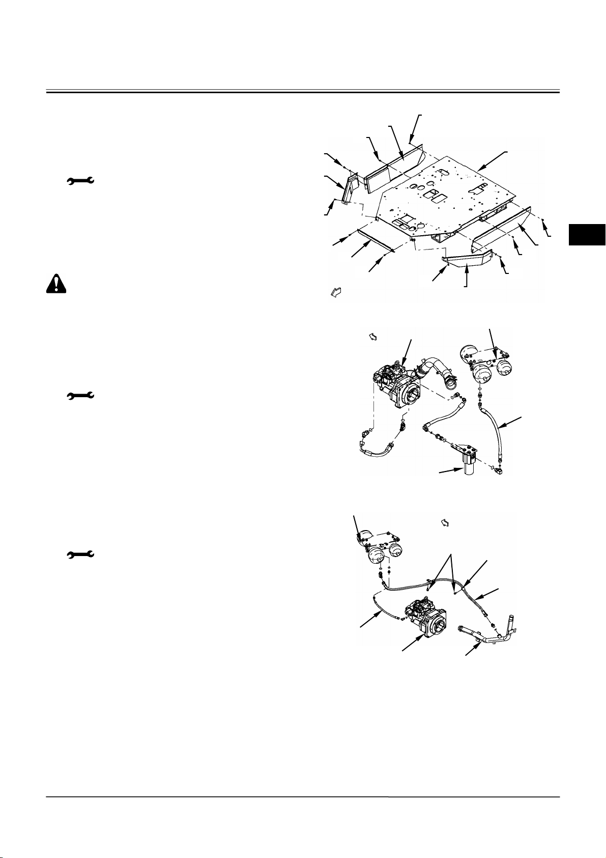
BODY (UPPERSTRUCTURE) / Cab
REMOVAL AND INSTALLATION OF CAB
Removal of Cab with Cockpit Attached
1. Remove sems bolts (2) (12 used) from covers (1)
(5 used). Remove covers (1) (5 used) from cockpit
(3).
: 17 mm
CAUTION: Hydraulic pressure is
accumulated in the hydraulic system by an
accumulator. Reduce pressure according to
the work point for each before disconnecting
the main, steering and brake system hoses.
2. Disconnect hose (5) between charging block (4)
and oil filter (6). Attach an identification tag onto
the disconnected hoses for assembling. Cap the
disconnected hoses.
: 22 mm, 27 mm
3. Remove sems bolts (7) (2 used) from clamps (8)
(2 used). Disconnect hose (9) between charging
block (4) and return pipe (10). Disconnect hose
(12) between main pump (11) and charging block
(4).
: 14 mm, 17 mm, 22 mm, 27 mm
2
1
2
2
Front
1
4
2
2
Front
1
2
2
Main Pump
6
Front
3
2
1
2
2
1
W4GB-02-01-001
4
5
W4GB-02-01-002
7
8
W2-1-1
12
11
10
9
W4GB-02-01-003
Page 66
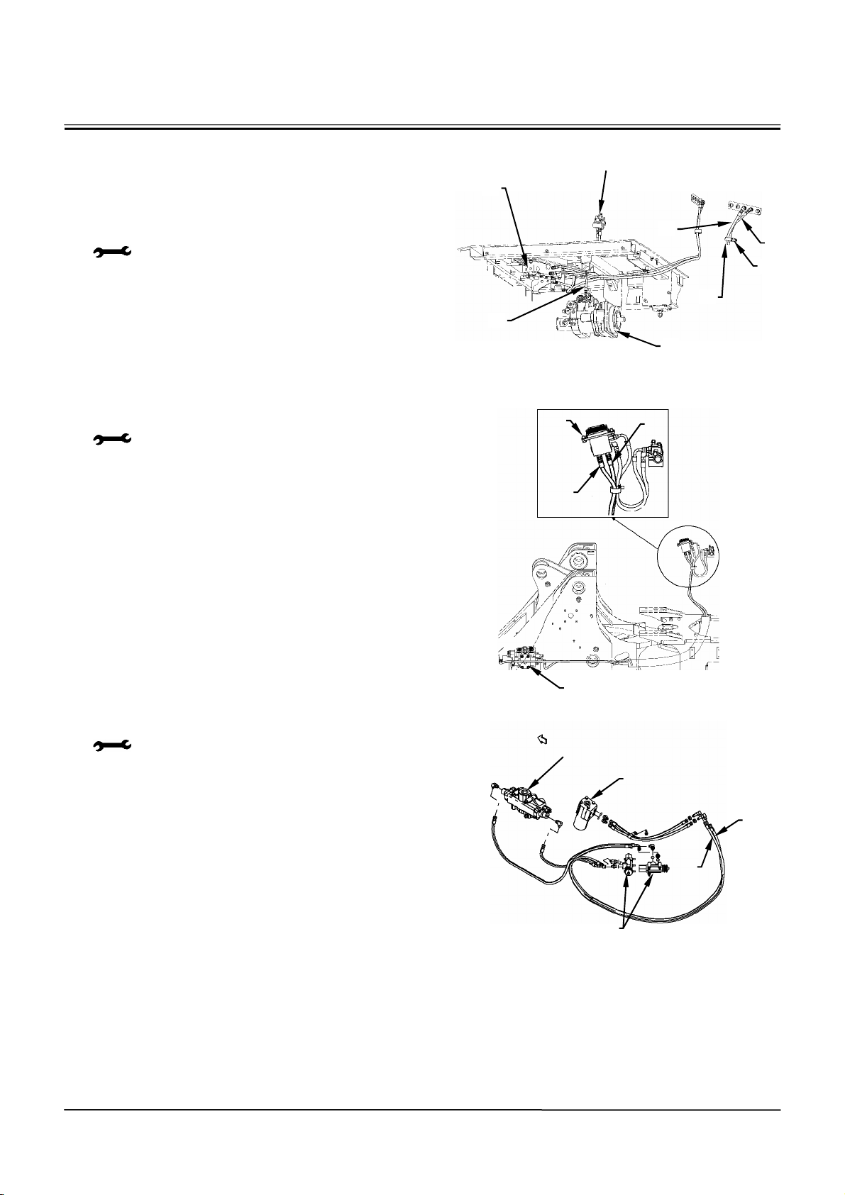
BODY (UPPERSTRUCTURE) / Cab
4. Remove sems bolts (17) (3 used) from clamps
(18) (3 used). Disconnect hose (19) between
charging block (4) and main pump (11).
Disconnect hoses (14, 16) between charging
block (4) and the rear side of hydraulic oil tank
(15).
: 14 mm, 17 mm
5. Disconnect hoses (21, 22) between pilot valve
(20) and main valve (23).
: 19 mm, 22 mm
6. Disconnect hoses (25, 26) between steering pilot
valve (24) and stop valve (27).
: 19 mm, 22 mm
4
19
Pilot Shut-Off Valve
14
11
15
(Rear Side
of Hydraulic
Oil Tank)
16
17
18
W4GB-02-01-004
20
22
21
23
W4GB-02-01-005
Front
Steering Valve
24
25
26
W2-1-2
27
W4GB-02-01-006
Page 67
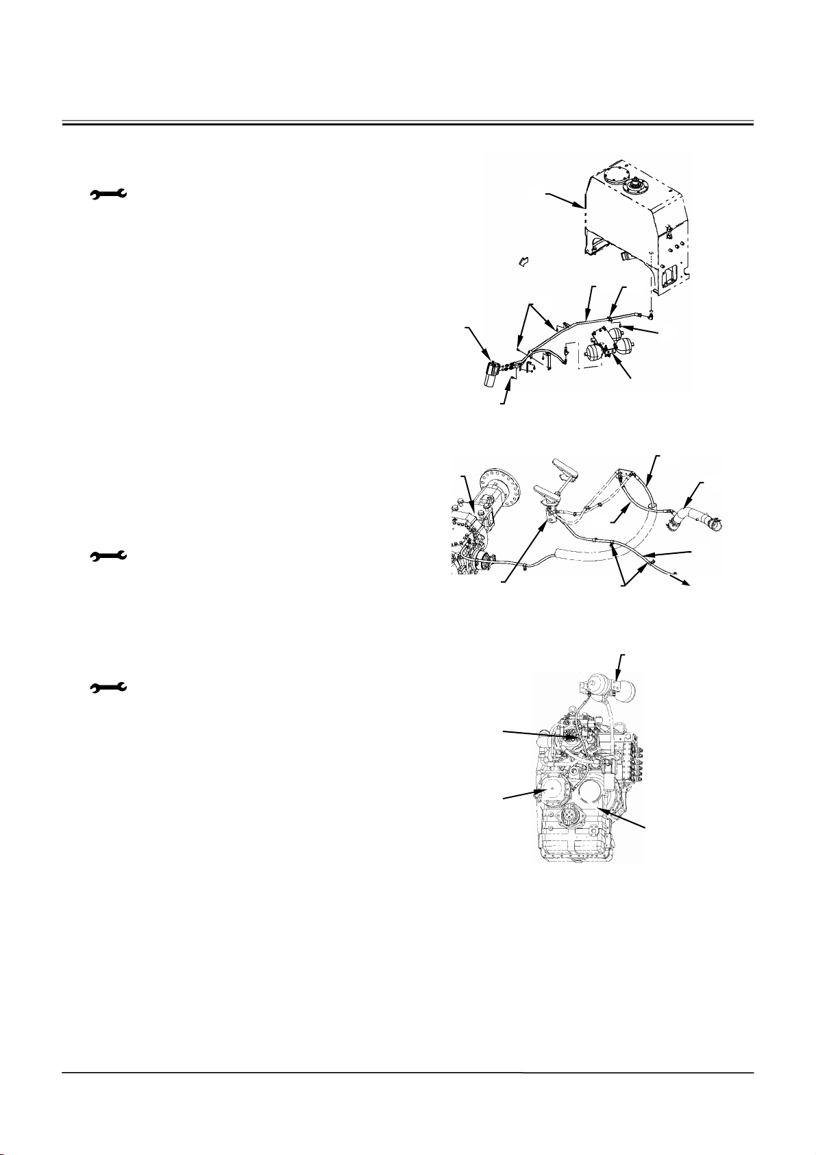
BODY (UPPERSTRUCTURE) / Cab
A
7. Remove sems bolts (29) (4 used) from clamps
(31) (4 used). Disconnect hose (30) between
steering pilot valve (28) and hydraulic oil tank (15).
: 17 mm, 22 mm, 27 mm
8. Remove sems bolts (38) (4 used) from clamps
(37) (4 used). Disconnect hose (33) between
brake valve (39) and front axle (32). Disconnect
hose (35) between brake valve (39) and suction
tube (34). Disconnect hose (36) between brake
valve (39) and the rear axle.
: 19 mm, 22 mm, 27 mm
9. Disconnect hose (40) between charging block (4)
and parking brake (41) in the transmission.
: 17 mm
15
Front
29
28
29
30
31
Charging Block
29
W4GB-02-01-007
32
35
39
37, 38
33
34
36
To R e a r
xle
W4GB-02-01-008
40
4
41
Transmission
W4GB-02-01-009
W2-1-3
Page 68
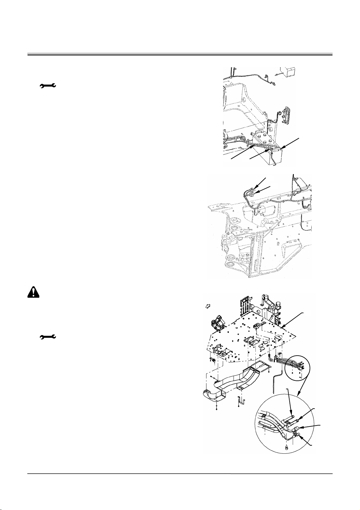
BODY (UPPERSTRUCTURE) / Cab
10. Remove bolt (43) for terminal minus from battery
(42) either left or right side. Disconnect battery
cable (44).
: 12 mm
11. Disconnect connectors (45, 46) of the wire
harness under the cab.
CAUTION: This machine uses new freon
R134a as refrigerant. Recover all the
refrigerants. Do not release them into the
atmosphere.
12. Disconnect refrigerant hoses (49, 50) attached to
the lower of cockpit (3).
: 17 mm, 19 mm, 24 mm, 27 mm
13. Drain off coolant from the radiator. Disconnect the
hose from heater pipings (47, 48).
42
44
43
W4GB-02-01-010
45
46
W4GB-02-01-011
Front
47
3
W2-1-4
48
49
50
W4GB-02-01-012
Page 69
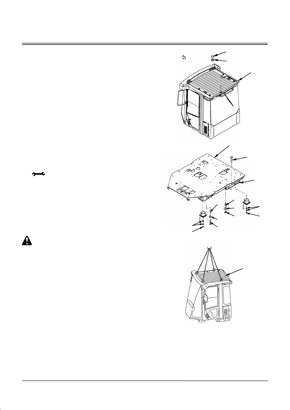
BODY (UPPERSTRUCTURE) / Cab
14. Remove caps (51) (4 used) and plates (52) (4
used) with the packing attached from the top of
cab (53). Install eyebolts (M16, Pitch 2.0 mm) (4
used) to cab (53).
15. Remove bolts (54, 63) (2 used for each), nuts (60)
(2 used) nuts, (57) (4 used), plates (59, 62) (2
used for each), spacers (58, 61) (2 used for each)
and washers (56) (8 used) which secure cockpit
(3) and frame (55).
: 17 mm, 30 mm
CAUTION: Cab (53) Weight:
1145 kg (2550 lb)
16. Attach a nylon sling onto the eyebolt on the top of
cab (53). Hoist and remove cab (53) from the
cockpit.
Front
51
52
53
58
59
60
W4GB-02-01-013
54
55
56
57
W4GB-02-01-014
56
57
3
61
62
63
53
W2-1-5
W4GB-02-01-015
Page 70
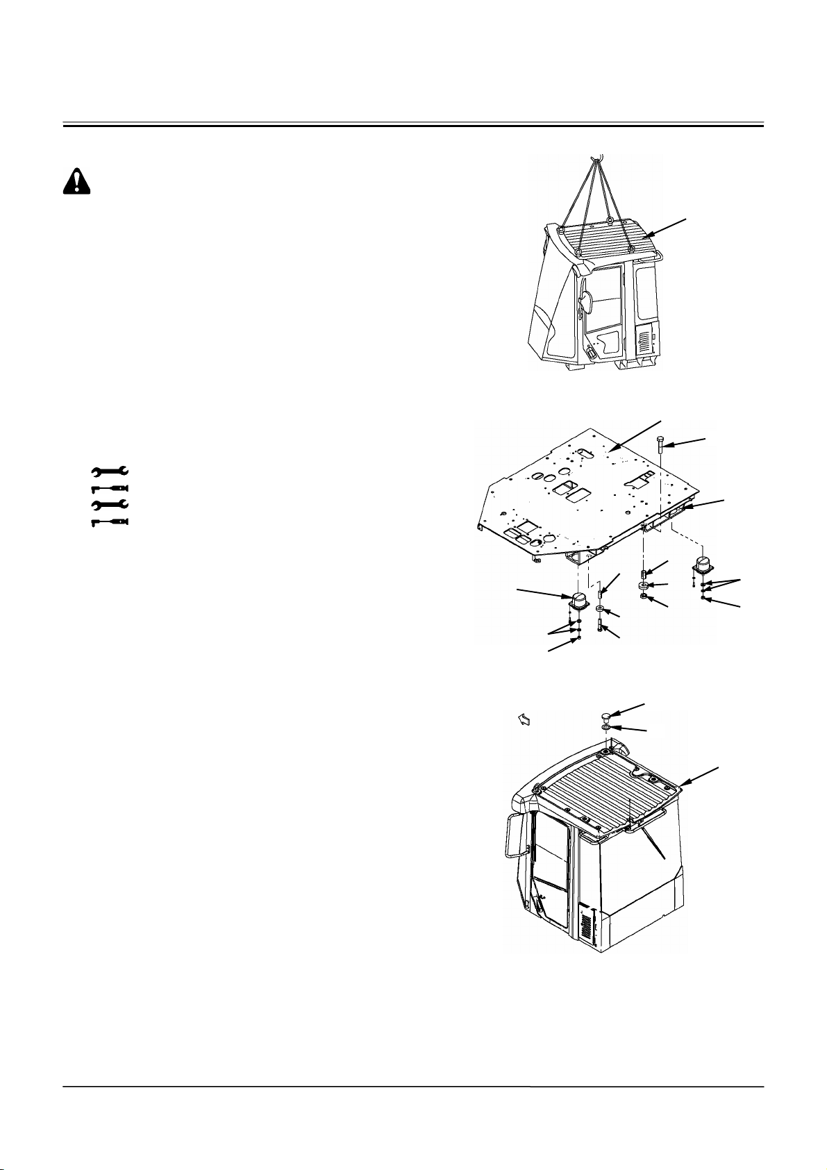
BODY (UPPERSTRUCTURE) / Cab
Installation of Cab
CAUTION: Cab (53) Weight:
1145 kg (2550 lb)
1. Attach a nylon sling onto an eyebolt on the top of
cab (53). Hoist and align cab (53) with the holes
on the cockpit.
2. Install cockpit (3) to frame (55) with bolts (54, 63)
(2 used for each), nuts (60) (2 used) nuts, (57) (4
used), plates (59, 62) (2 used for each), spacers
(58, 61) (2 used for each) and washers (56) (8
used). At this time, install washer (56) between
the cockpit mount and frame (55).
: 17 mm
: 50 N⋅m (5 kgf⋅m, 36 lbf·ft)
: 30 mm
: 137 N⋅m (14 kgf⋅m, 101 lbf·ft)
3. Remove eyebolts (4 used) from the top of cab (53).
Install caps (51) (4 used) and plates (52) (4 used)
with the packing attached to cab (53).
Cockpit Mount
Front
56
57
61
62
63
51
52
53
W4GB-02-01-015
3
54
55
58
59
60
56
57
W4GB-02-01-014
W2-1-6
53
W4GB-02-01-013
Page 71
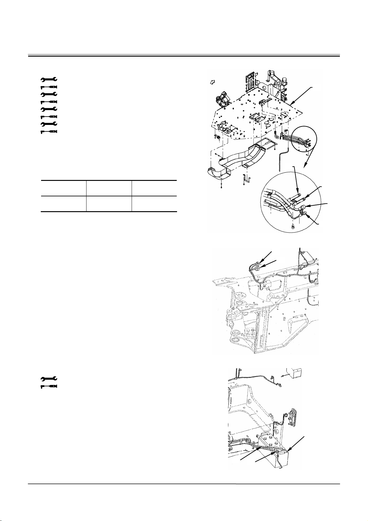
BODY (UPPERSTRUCTURE) / Cab
4. Connect hoses (49, 50) under cockpit (3).
Connect heater pipings (47, 48).
: 17 mm
: 24.5 N⋅m (2.5 kgf⋅m, 18 lbf·ft)
: 19 mm
: 29.4 N⋅m (3 kgf⋅m, 21.5 lbf·ft)
: 24 mm
: 39 N⋅m (4 kgf⋅m, 28.5 lbf·ft)
: 27 mm
: 78 N⋅m (8 kgf⋅m, 57.5 lbf·ft)
5. This machine uses new freon R134a as
refrigerant. Check for any gas leakage after
injecting gas for the required amount.
Type Refrigerant
Number
Q’ty
kg (lb)
HFC R134a 1.05±0.05
(2.32±0.11)
6. Connect connectors (45, 46) of the wire harness
under the cab.
7. Connect battery cable (44) to terminal minus of
battery (42) with bolt (43).
: 12 mm
: 10 N⋅m (1 kgf⋅m, 7.2 lbf·ft)
Front
47
3
48
49
50
W4GB-02-01-012
45
46
W4GB-02-01-011
W2-1-7
44
42
43
W4GB-02-01-010
Page 72
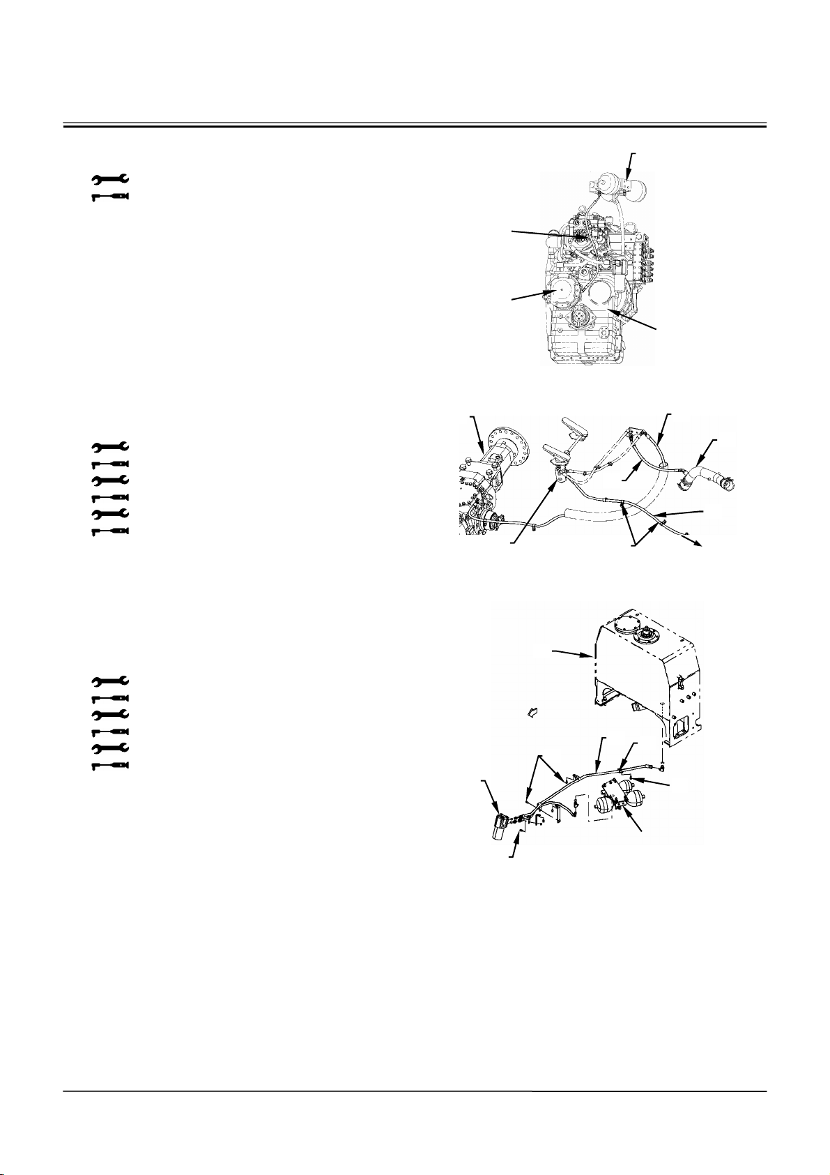
BODY (UPPERSTRUCTURE) / Cab
A
8. Connect hose (40) between charging block (4)
and parking brake (41) in the transmission.
: 17 mm
: 39 N⋅m (4 kgf⋅m, 28.5 lbf·ft)
9. Connect hose (33) between brake valve (39) and
front axle (32). Connect hose (35) between brake
valve (39) and suction tube (34). Connect hose
(36) between brake valve (39) and the rear axle.
Secure clamps (37) (4 used) to the frame with
sems bolts (38) (4 used).
: 19 mm
: 29.5 N⋅m (3 kgf⋅m, 21.5 lbf·ft)
: 22 mm
: 39 N⋅m (4 kgf⋅m, 28.5 lbf·ft)
: 27 mm
: 78 N⋅m (8 kgf⋅m, 57.5 lbf·ft)
10. Connect hose (30) between steering pilot valve
(28) and hydraulic oil tank (15). Secure clamps
(31) (4 used) to the frame with sems bolts (29) (4
used).
: 17 mm
: 24.5 N⋅m (2.5 kgf⋅m, 18 lbf·ft)
: 22 mm
: 39 N⋅m (4 kgf⋅m, 28.5 lbf·ft)
: 27 mm
: 78 N⋅m (8 kgf⋅m, 57.5 lbf·ft)
40
41
4
Transmission
W4GB-02-01-009
32
35
39
37, 38
33
34
36
To R e a r
xle
W4GB-02-01-008
15
Front
30
29
25
31
29
Charging Block
29
W4GB-02-01-007
W2-1-8
Page 73
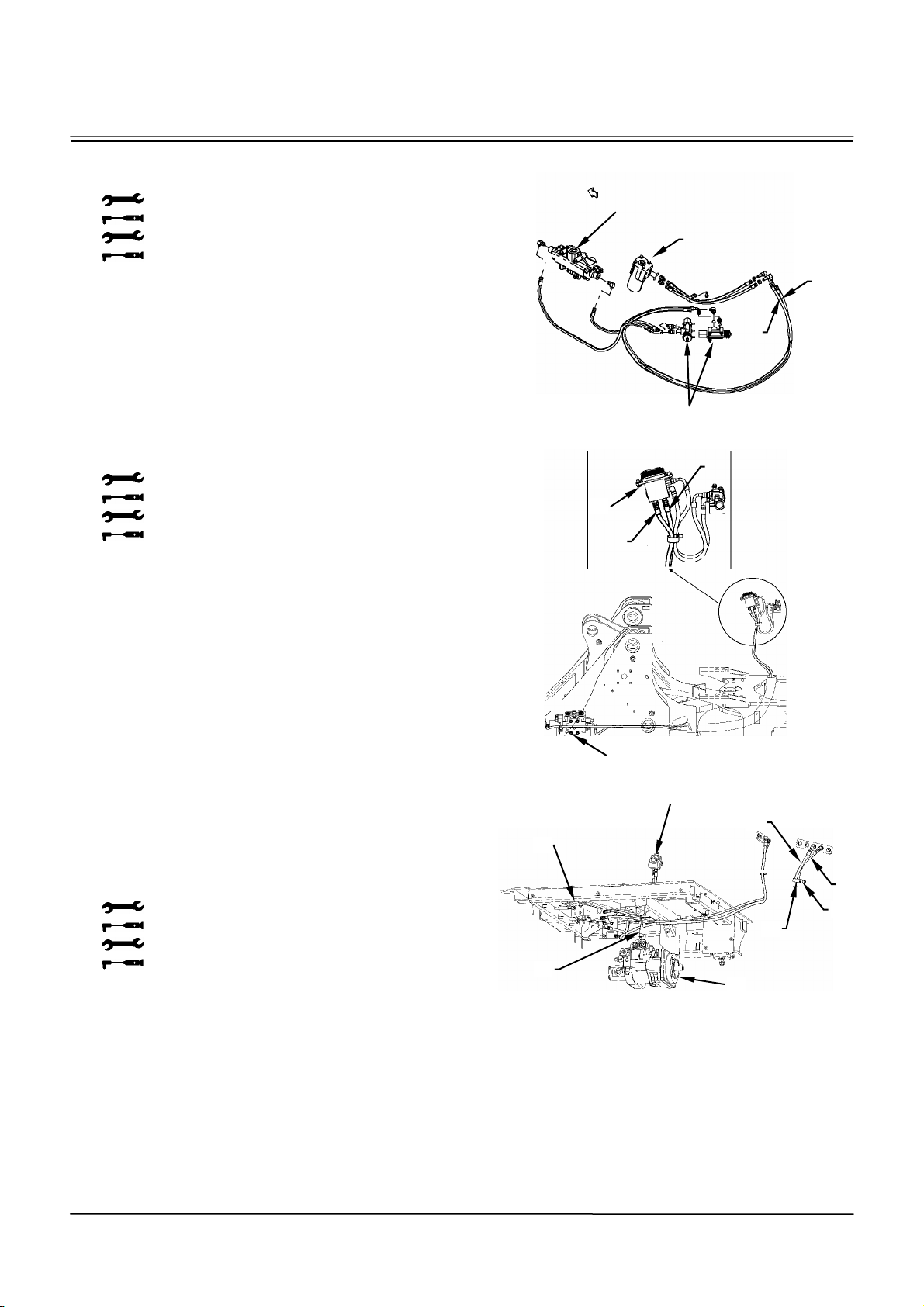
BODY (UPPERSTRUCTURE) / Cab
11. Connect hoses (25, 26) between steering pilot
valve (24) and stop valve (27).
: 19 mm
: 29.5 N⋅m (3 kgf⋅m, 21.5 lbf·ft)
: 22 mm
: 39 N⋅m (4 kgf⋅m, 28.5 lbf·ft)
12. Connect hoses (21, 22) between pilot valve (20)
and main valve (23).
: 19 mm
: 29.5 N⋅m (3 kgf⋅m, 21.5 lbf·ft)
: 22 mm
: 39 N⋅m (4 kgf⋅m, 28.5 lbf·ft)
13. Connect hose (19) between charging block (4)
and main pump (11). Connect hoses (14, 16)
between charging block (4) and the rear side of
hydraulic oil tank (15).
Secure clamps (18) (3 used) to the frame with
sems bolts (17) (3 used).
: 14 mm
: 20 N⋅m (2 kgf⋅m, 14.5 lbf·ft)
: 17 mm
: 24.5 N⋅m (2.5 kgf⋅m, 18 lbf·ft)
Front
Steering Valve
24
25
26
27
W4GB-02-01-006
21
20
22
14
18
W4GB-02-01-005
15
Rear Side
of Hydraulic
Oil Tank
16
17
23
Pilot Shut-Off Valve
4
19
11
W4GB-02-01-004
W2-1-9
Page 74
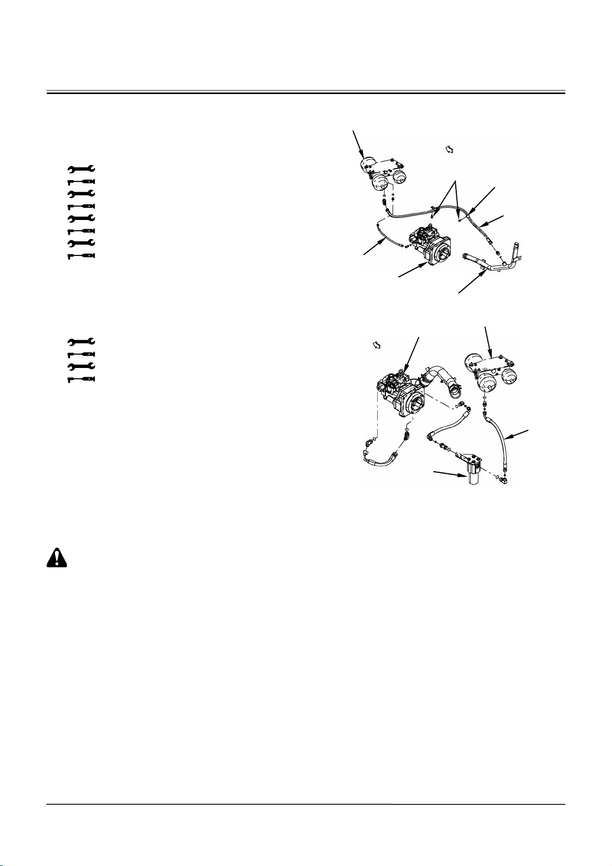
BODY (UPPERSTRUCTURE) / Cab
14. Connect hose (9) between charging block (4) and
return pipe (10). Secure clamps (8) (2 used) to the
frame with sems bolts (7) (2 used). Connect hose
(12) between main pump (11) and charging block
(4).
: 14 mm
: 20 N⋅m (2 kgf⋅m, 14.5 lbf·ft)
: 17 mm
: 24.5 N⋅m (2.5 kgf⋅m, 18 lbf·ft)
: 22 mm
: 39 N⋅m (4 kgf⋅m, 28.5 lbf·ft)
: 27 mm
: 78 N⋅m (8 kgf⋅m, 57.5 lbf·ft)
15. Connect hose (5) between charging block (4) and
oil filter (6).
: 22 mm
: 39 N⋅m (4 kgf⋅m, 28.5 lbf·ft)
: 27 mm
: 78 N⋅m (8 kgf⋅m, 57.5 lbf·ft)
16. Add coolant to the radiator. Start the engine and
the test run.
Check for any oil leakage at the hose connections.
4
12
11
Front
10
7
8
9
W4GB-02-01-003
Front
Main Pump
6
4
5
W4GB-02-01-002
CAUTION: Wear safety goggles and gloves
when checking oil leaks. Apply cardboard or
laminated wood at the check point.
High-pressure oil may cause serious injury to
the skin and eyes.
W2-1-10
Page 75
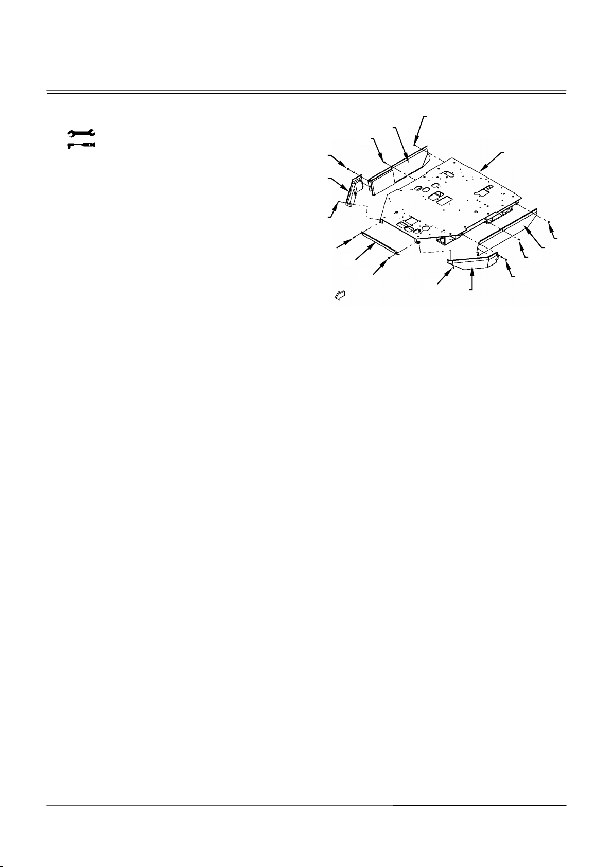
BODY (UPPERSTRUCTURE) / Cab
17. Install covers (1) (5 used) to cockpit (3) with sems
bolts (2) (12 used).
: 17 mm
: 24.5 N⋅m (2.5 kgf⋅m, 18 lbf·ft)
2
1
2
Front
2
1
2
3
2
1
2
2
1
2
2
1
2
W4GB-02-01-001
W2-1-11
Page 76

(Blank)
BODY (UPPERSTRUCTURE) / Cab
W2-1-12
Page 77
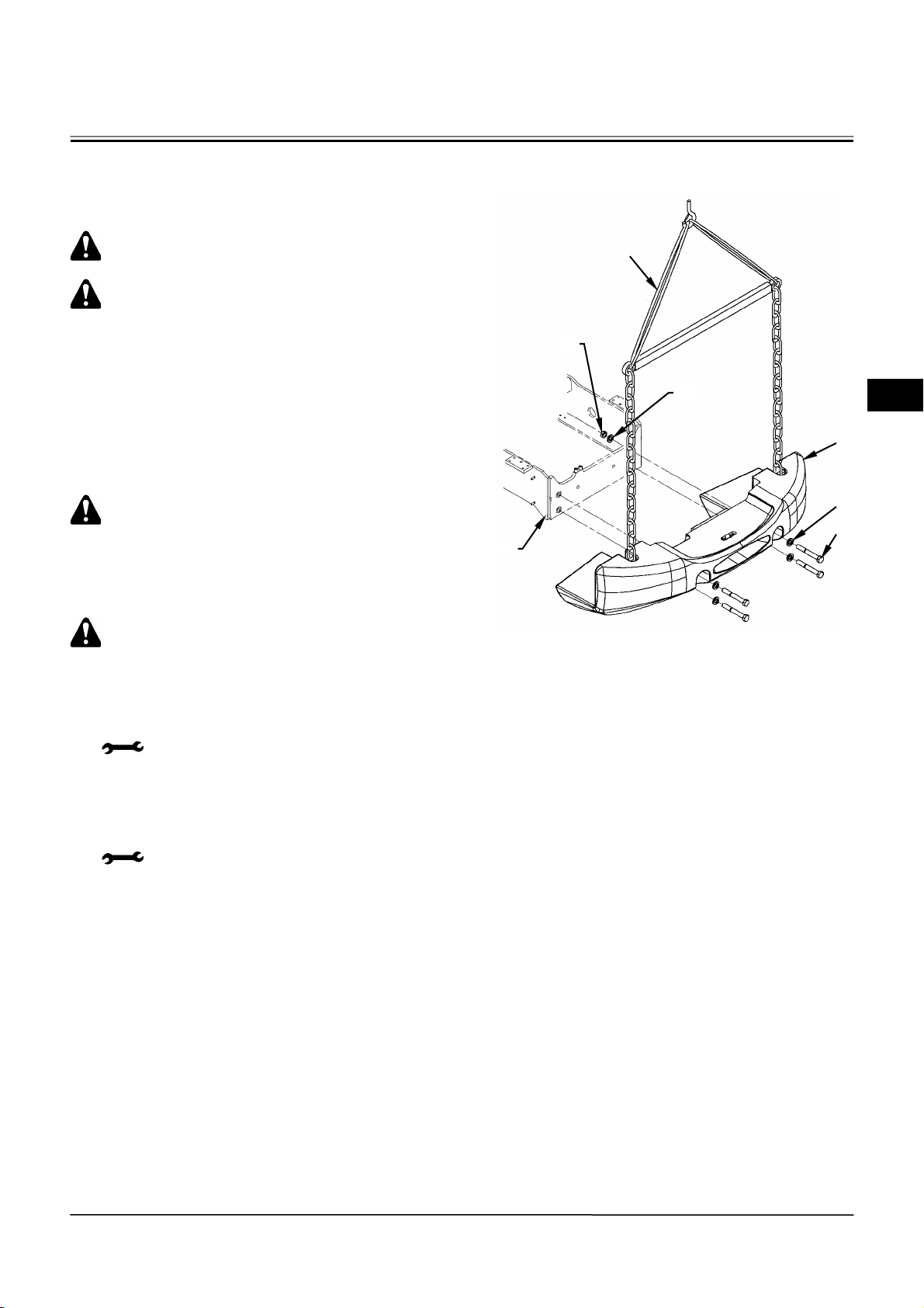
BODY (UPPERSTRUCTURE) / Counterweight
REMOVAL AND INSTALLATION OF COUNTERWEIGHT
Removal
CAUTION: Counterweight weight:
1810 kg (4000 lb)
CAUTION: 1. Park the machine on a flat
place and stop the engine.
2. Put a chock and apply the
parking brake in order not to
move the machine.
3. Lower the bucket onto the
ground. Release hydraulic
pressure in the hydraulic
device.
1. Open the rear grill.
CAUTION: When removing counterweight (3)
with the rear grill closed, the rear grill may be
damaged.
2. Install a lifting tool to counterweight (3). Hoist
counterweight (3) a little.
CAUTION: When hoisting counterweight (3)
too much, it difficult to remove bolt (5) and
the screw part may be damaged.
3. Remove nuts (1) (2 used) and washers (2) (2
used).
: 46 mm
4. Loosen bolts (5) (4 used). Remove bolts (5) (4
used) and washers (4) (4 used) from
counterweight (3) while finely adjusting the hoist
of counterweight (3).
: 46 mm
5. Move counterweight (3) to the rear side of frame
(6) and remove counterweight (3).
Lifting Tool
1
2
3
4
5
6
W4GB-02-02-001
W2-2-1
Page 78
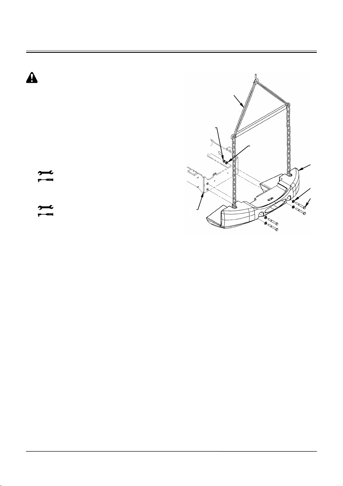
BODY (UPPERSTRUCTURE) / Counterweight
Installation
CAUTION: Counterweight weight:
1810 kg (4000 lb)
1. Hoist counterweight (3) by using a lifting tool.
Move counterweight (3) to about 200 mm (8 in) in
front of the counterweight (3) mounting part of
frame (6).
2. Align the screw holes on counterweight (3) and
frame (6). Place counterweight (3) onto frame (6).
3. Install counterweight (3) to frame (6) with blots (5)
(4 used) and washers (4) (4 used).
: 46 mm
: 1510 N⋅m (154 kgf⋅m, 1110 lbf·ft)
4. Install nuts (1) (2 used) and washers (2) (2 used)
to bolts (5) (2 used) on the upper side.
: 46 mm
: 1510 N⋅m (154 kgf⋅m, 1110 lbf·ft)
Lifting Tool
1
2
3
4
5
6
W4GB-02-02-001
W2-2-2
Page 79
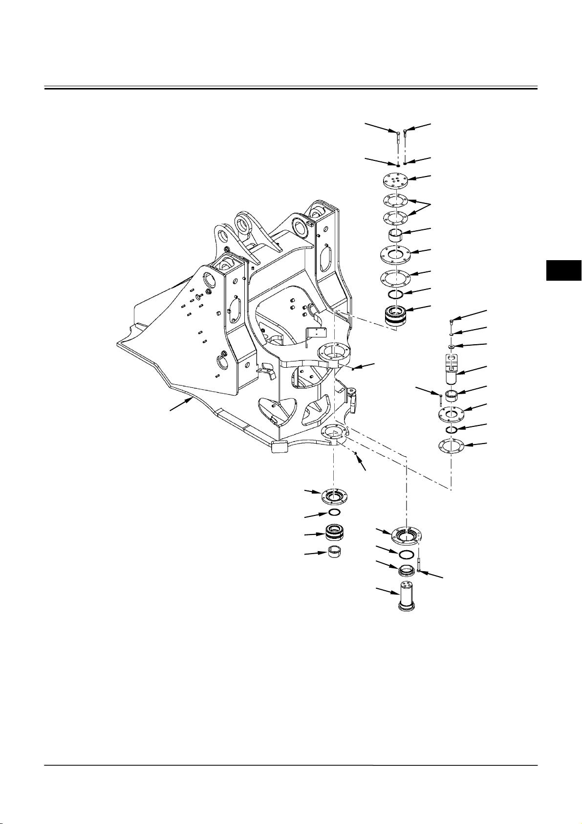
BODY (UPPERSTRUCTURE) / Center Hinge
DISASSEMBLY OF CENTER HINGE
2
3
25
1
24
16
1
4
5
6
7
8
9
10
11
12
13
14
15
17
18
8
24
23
18
10
15
19
9
20
21
22
1 - Washer (10 Used) 8 - Shim (2 Used) 14 - Pin 20 - Bushing
2 - Bolt (4 Used) 9 - Dust Seal (2 Used) 15 - Bushing (2 Used) 21 - Bolt (6 Used)
3 - Bolt (6 Used) 10 - Bearing (2 Used) 16 - Bolt (6 Used) 22 - Pin
4 - Flange 11 - Bolt 17 - Cap 23 - Cap
5 - Shim (2 Used) 12 - Washer 18 - Dust Seal (2 Used) 24 - Grease Fitting (2 Used)
6 - Bushing 13 - Washer 19 - Cap 25 - Front Frame
7 - Cap
W4GB-02-03-021
W2-3-1
Page 80
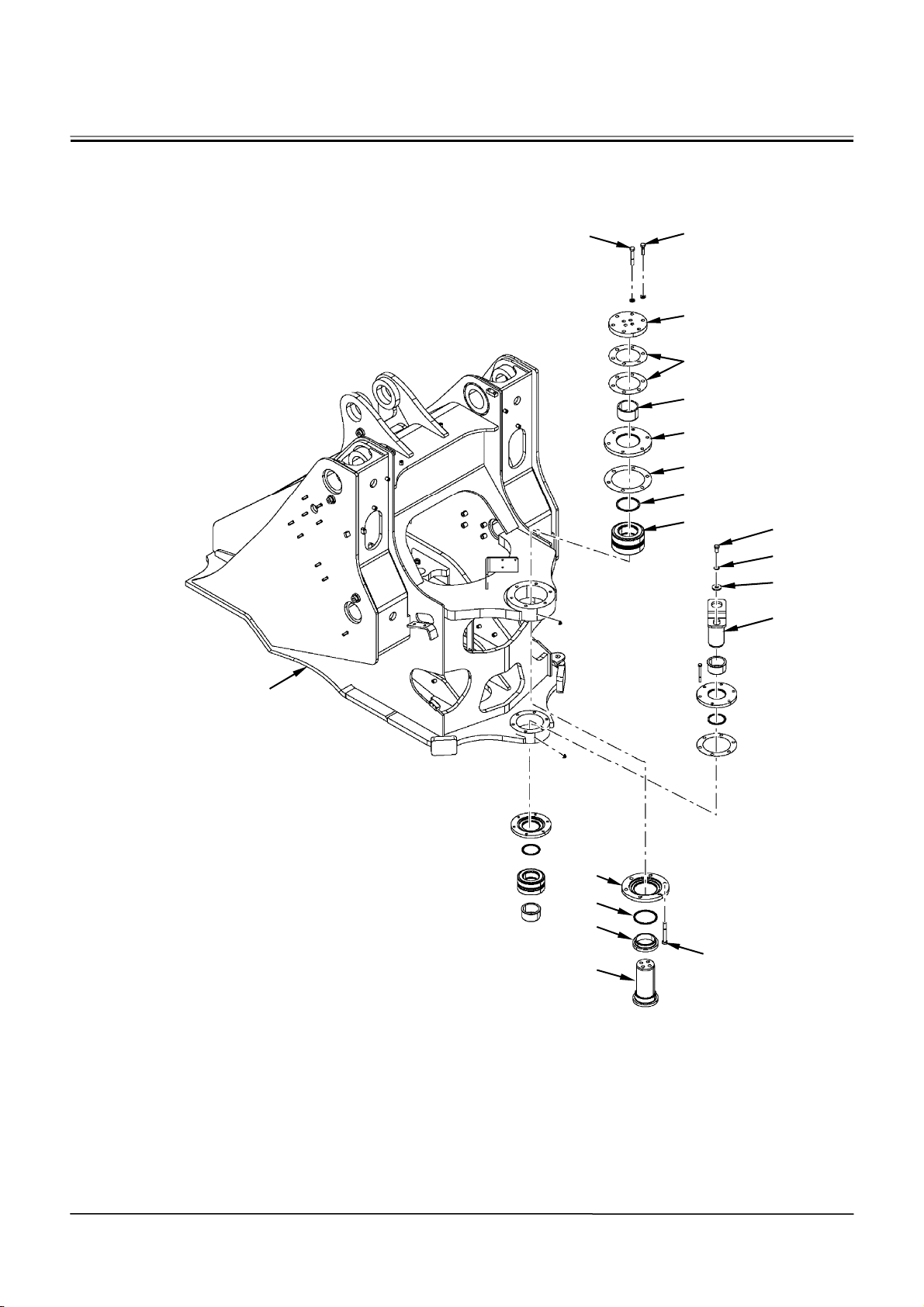
BODY (UPPERSTRUCTURE) / Center Hinge
2
3
4
5
6
7
8
9
25
19
9
20
22
10
11
12
13
14
21
W4GB-02-03-021
W2-3-2
Page 81
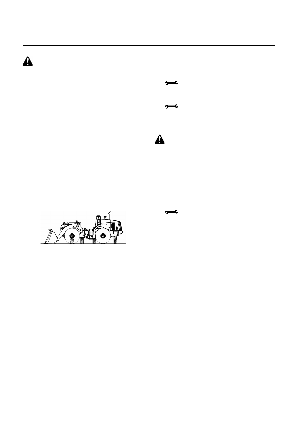
BODY (UPPERSTRUCTURE) / Center Hinge
Disassembly of Center Hinge
CAUTION: The center hinge is required to
disassemble for the major maintenance work
such as removal of the front frame from the
rear frame. At this time, move the machine
into the factory.
Preparation
Carry out the following procedures before
disassembling the center hinge.
1. Remove the cab and the cockpit.
2. Remove the mounting component between the
front frame and the rear frame.
• Propeller Shaft
• Steering Cylinder
• Hydraulic Hose
• Brake Piping
• Wire Harness
Removal of Hinge Pin
1. Support the front frame and the rear frame by
using firm support stands.
W4GB-02-03-002
2. Remove bolts (2) (4 used) and bolts (3) (6 used)
from flange (4) of the upper hinge part. Remove
flange (4), shims (5) (2 used) and pin (22) from
front frame (25).
: 24 mm
3. Remove bolt (11) and washers (12, 13) from pin
(14). Remove pin (14) from front frame (25).
: 24 mm
4. Remove bushing (6) from front frame (25).
(Remove bushing (6) after cutting by gas or
pulling out by welding a cardboard.)
CAUTION: Front frame (25) weight:
2080 kg (4600 lb)
5. Attach a nylon sling onto front frame (25). Hoist
and move front frame (25) so that bearing (10)
can be removed.
6. Remove bushing (20) from front frame (25).
7. Remove bolts (21) (6 used) from cap (19).
Remove caps (7, 19) and shim (8) from front
frame (25).
: 24 mm
8. Remove dust seals (9) (2 used) from caps (7, 19).
9. Remove bearing (10) from front frame (25).
W2-3-3
Page 82
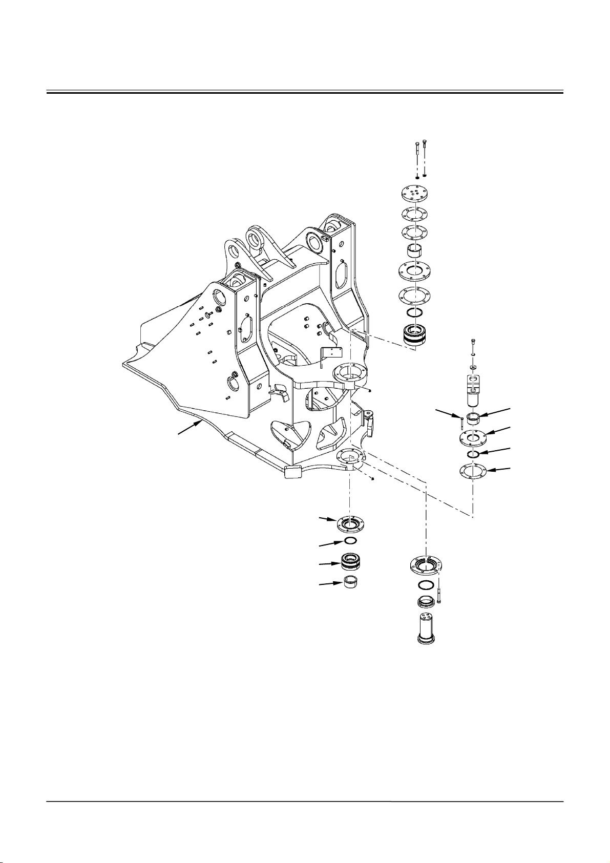
BODY (UPPERSTRUCTURE) / Center Hinge
16
25
23
18
10
15
15
17
18
8
W4GB-02-03-021
W2-3-4
Page 83

BODY (UPPERSTRUCTURE) / Center Hinge
10. Remove bolts (16) (6 used) from cap (17).
Remove caps (17, 23) and shim (8) from front
frame (25).
: 17 mm
11. Remove dust seals (18) (2 used) from caps (17,
23).
12. Remove bearing (10) from front frame (25).
13. Remove bushings (15) (2 used) from the lower
hinge part of the rear frame.
W2-3-5
Page 84
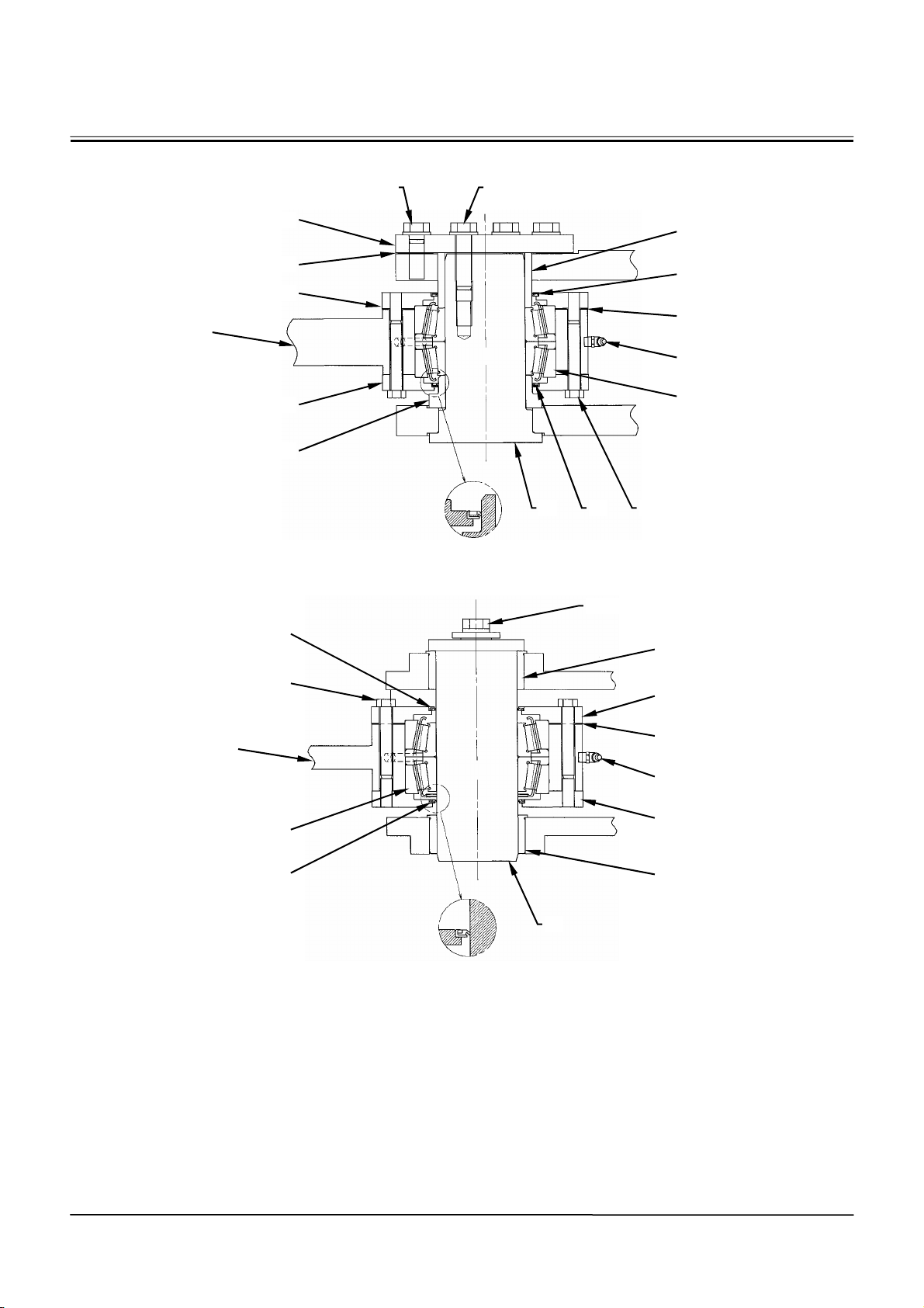
BODY (UPPERSTRUCTURE) / Center Hinge
ASSEMBLY OF CENTER HINGE
Upper Hinge
4
1, 3 1, 2
6
Lower Hinge Pin
25
18
16
5
7
19
20
922
11, 12, 13
9
8
24
10
21
W4GB-02-03-003
15
17
25
10
18
14
8
24
23
15
1 - Washer (10 Used) 8 - Shim (2 Used) 14 - Pin 20 - Bushing
2 - Bolt (4 Used) 9 - Dust Seal (2 Used) 15 - Bushing (2 Used) 21 - Bolt (6 Used)
3 - Bolt (6 Used) 10 - Bearing (2 Used) 16 - Bolt (6 Used) 22 - Pin
4 - Flange 11 - Bolt 17 - Cap 23 - Cap
5 - Shim (2 Used) 12 - Washer 18 - Dust Seal (2 Used) 24 - Grease Fitting (2 Used)
6 - Bushing 13 - Washer 19 - Cap 25 - Front Frame
7 - Cap
W4GB-02-03-004
W2-3-6
Page 85
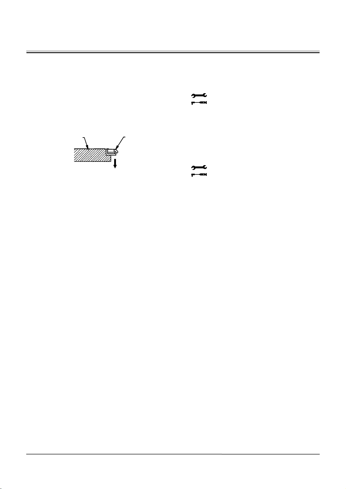
BODY (UPPERSTRUCTURE) / Center Hinge
Assembly of Center Hinge
1. Continuously apply LOCTITE #262 onto the outer
circumference of dust seal (18). Lightly tap and
insert dust seal (18) into cap (17) by using a
hammer. Wipe out the stick-out LOCTITE #262 by
using a waste.
Install dust seal (18) to cap (23) in the same way.
IMPORTANT: Check the direction of dust seal (18).
Install dust seal (18) with the wider
rubber side facing to the unpainted
side of caps (17, 23).
17, 23
18
Face the lip to the outer side
(painted side of the cap)
W4GB-02-03-005
2. Insert dust seals (9) (2 used) into caps (7, 19) in
the same way.
3. Insert bearing (10) into the upper hinge part of
front frame (25).
4. Add grease through grease fitting (24) into the
inside of bearing (10) while rotating bearing (10).
5. Insert bearing (10) into the lower hinge part of
front frame (25). Add grease through grease
fitting (24).
6. Install caps (7, 19) and shim (8) to the upper
hinge part of front frame (25). Apply LOCTITE
#262 onto bolts (21) (6 used). Install caps (7, 19)
to front frame (25) with bolts (21) (6 used).
: 24 mm
: 224 N⋅m (23 kgf⋅m, 165 lbf·ft)
7. Tap the space among caps (7, 19) and dust seals
(9) (2 used) by using an iron nail.
8. Install caps (17, 23) and shim (8) to the lower
hinge part of front frame (25). Apply LOCTITE
#262 onto bolts (16) (6 used). Install caps (17, 23)
to front frame (25) with bolts (16) (6 used).
: 17 mm
: 88 N⋅m (9 kgf⋅m, 65 lbf·ft)
9. Tap the space among caps (17, 23) and dust
seals (18) (2 used) by using an iron nail.
W2-3-7
Page 86
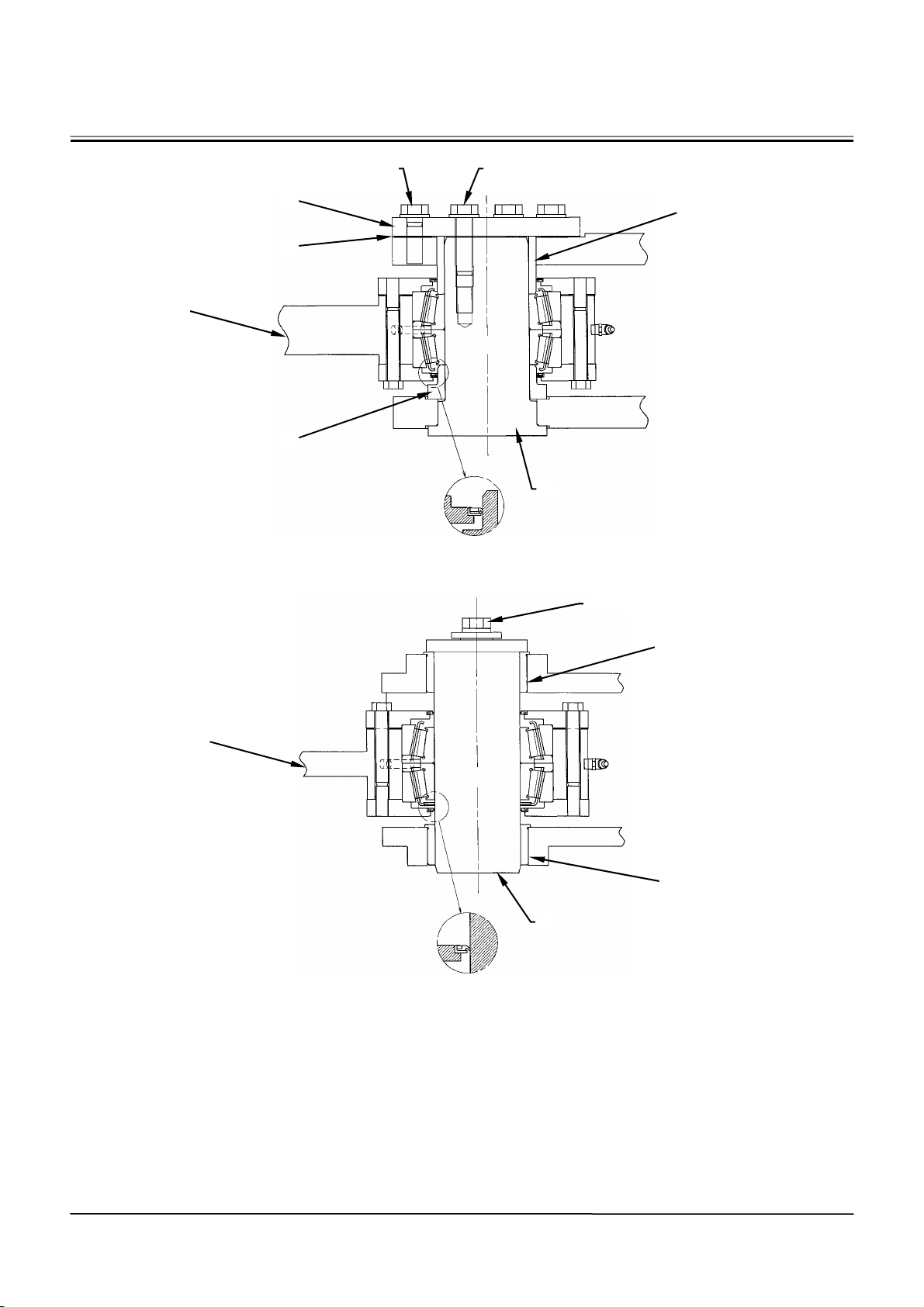
BODY (UPPERSTRUCTURE) / Center Hinge
Upper Hinge
25
Lower Hinge Pin
4
5
20
1, 3 1, 2
6
22
W4GB-02-03-003
11, 12, 13
25
15
15
14
W4GB-02-03-004
W2-3-8
Page 87
BODY (UPPERSTRUCTURE) / Center Hinge
10. Insert bushings (15) (2 used) into the lower hinge
part of the rear frame.
CAUTION: Front frame (25) weight:
2080 kg (4600 lb)
11. Attach a nylon sling onto front frame (25). Hoist
and align front frame (25) with the center hinge
pin holes on the rear frame.
12. Install pin (22), bushings (6, 20), shims (5) (2
used) and flange (4) to the upper hinge part.
Tighten bolts (2) (4 used), bolts (3) (6 used) and
washers (1) (10 used).
: 24 mm
: 224 N⋅m (23 kgf⋅m, 165 lbf·ft)
13. Insert pin (14) into the lower hinge part. Tighten
bolt (11) and washers (12, 13).
: 24 mm (0.94 in)
: 86.9 N⋅m (8.9 kgf⋅m, 64 lbf·ft)
W2-3-9
Page 88

(Blank)
BODY (UPPERSTRUCTURE) / Center Hinge
W2-3-10
Page 89
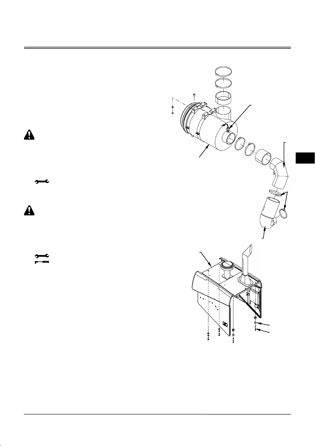
BODY (UPPERSTRUCTURE) / Hood
A
REMOVAL AND INSTALLATION OF HOOD
Removal
1. Open the left and right side covers.
2. Loosen hose bands (3) (2 used) which secure
intake hose (4). Disconnect intake hose (4) from
pipe (2) and the engine.
3. Disconnect the harness for sensor (1) at the
connector part.
CAUTION: The hood (5) assembly weight:
159 kg (350 lb)
4. Attach a nylon sling onto hood (5). Hoist and hold
hood (5). Remove bolts (7) (4 used) and washers
(6) (4 used) from hood (5). Hoist and remove hood
(5) from the frame.
: 17 mm
Installation
1
2
ir Cleaner
3
CAUTION: The hood (5) assembly weight:
159 kg (350 lb)
1. Attach a nylon sling onto hood (5). Hoist hood (5).
Align the exhaust pipe and the vent of the muffler.
Install hood (5) to the frame with bolts (7) (4 used)
and washers (6) (4 used).
: 17 mm
: 50 N⋅m (5 kgf⋅m, 36 lbf·ft)
2. Connect the harness for sensor (1) at the
connector part.
3. Connect intake hose (4) to the engine and pipe (2).
Secure intake hose (4) with hose bands (3) (2 used).
4. Shut the left and right side covers.
5
4
W4GB-02-03-007
6
7
W4GB-02-03-006
W2-4-1
Page 90

(Blank)
BODY (UPPERSTRUCTURE) / Hood
W2-4-2
Page 91
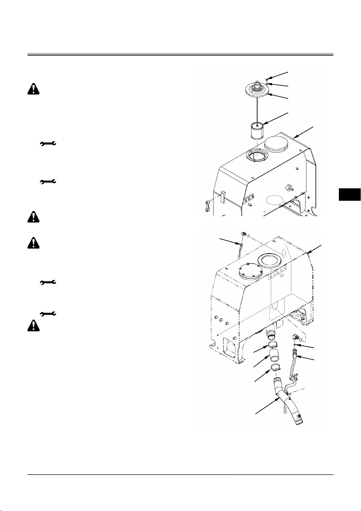
BODY (UPPERSTRUCTURE) / Hydraulic Oil Tank
REMOVAL AND INSTALLATION OF HYDRAULIC OIL TANK
CAUTION: Hydraulic oil tank (5) weight:
215 kg (475 lb)
Removal
1. Remove the hood. (Refer to W2-4-1.)
2. Remove the left and right side fenders.
: 17 mm
3. Remove bolts (1) (6 used) and washers (2) (6
used) from cover (3). Remove cover (3) and
suction filter (4) from hydraulic oil tank (5).
: 14 mm
4. Drain hydraulic oil from the suction filter mounting
part of hydraulic oil tank (5) by using a pump.
CAUTION: Drain hydraulic oil from the
suction pipe at the bottom of hydraulic oil
tank (5).
CAUTION: Attach an identification tag onto
each hose connected to hydraulic oil tank (5)
for assembling.
5. Disconnect hose (6) from hydraulic oil tank (5).
: 22 mm
6. Disconnect hose (8) and remove O-ring (7) from
hydraulic oil tank (5).
: 36 mm
1
2
3
4
5
W4GB-02-03-010
6
5
CAUTION: O-ring (7) cannot be reused.
7. Loosen hose clamps (9) (2 used). Disconnect
hose (10) from hydraulic oil tank (5) and pipe (11).
W2-5-1
10
9
7
8
9
11
W4GB-02-03-011
Page 92
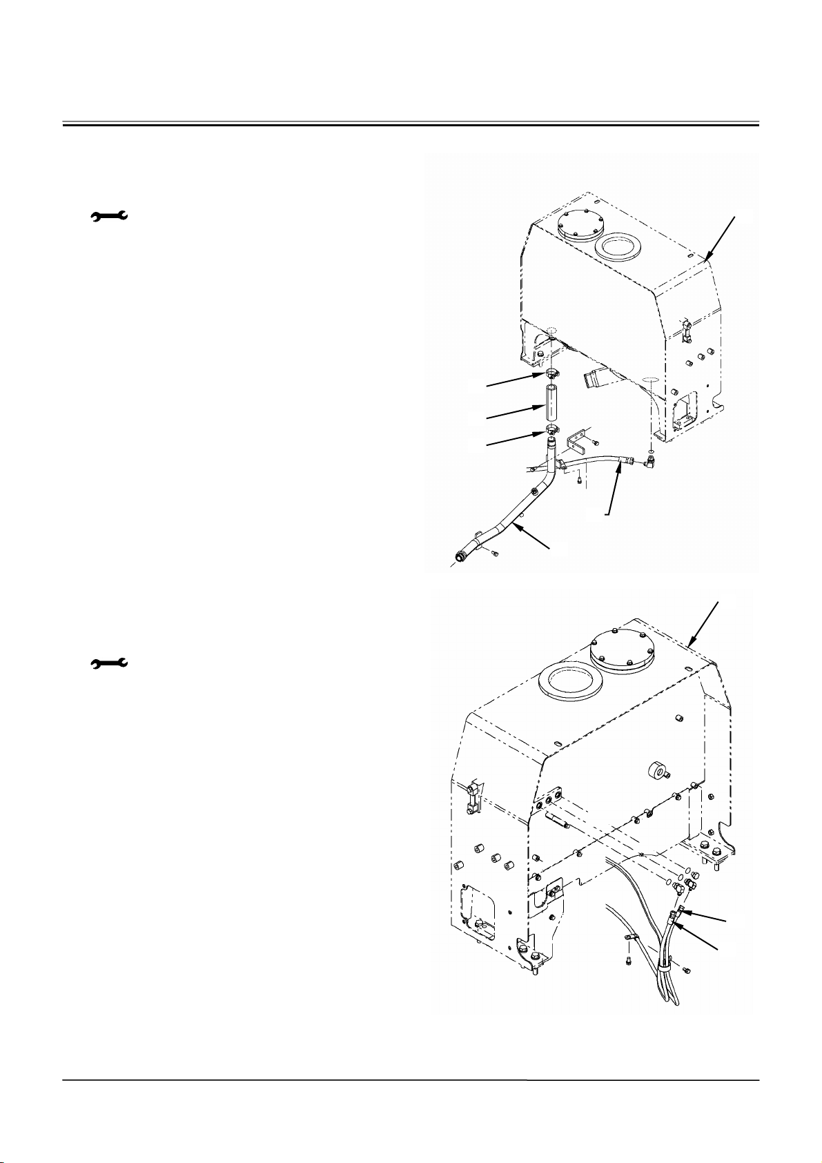
BODY (UPPERSTRUCTURE) / Hydraulic Oil Tank
8. Loosen hose clamps (12) (2 used). Disconnect
hose (13) from hydraulic oil tank (5) and pipe (15).
9. Disconnect hose (14) from hydraulic oil tank (5).
: 27 mm
10. Disconnect hoses (16, 17) from hydraulic oil tank
(5).
: 17 mm
5
12
13
12
14
15
W4GB-02-03-012
5
W2-5-2
16
17
W4GB-02-03-013
Page 93
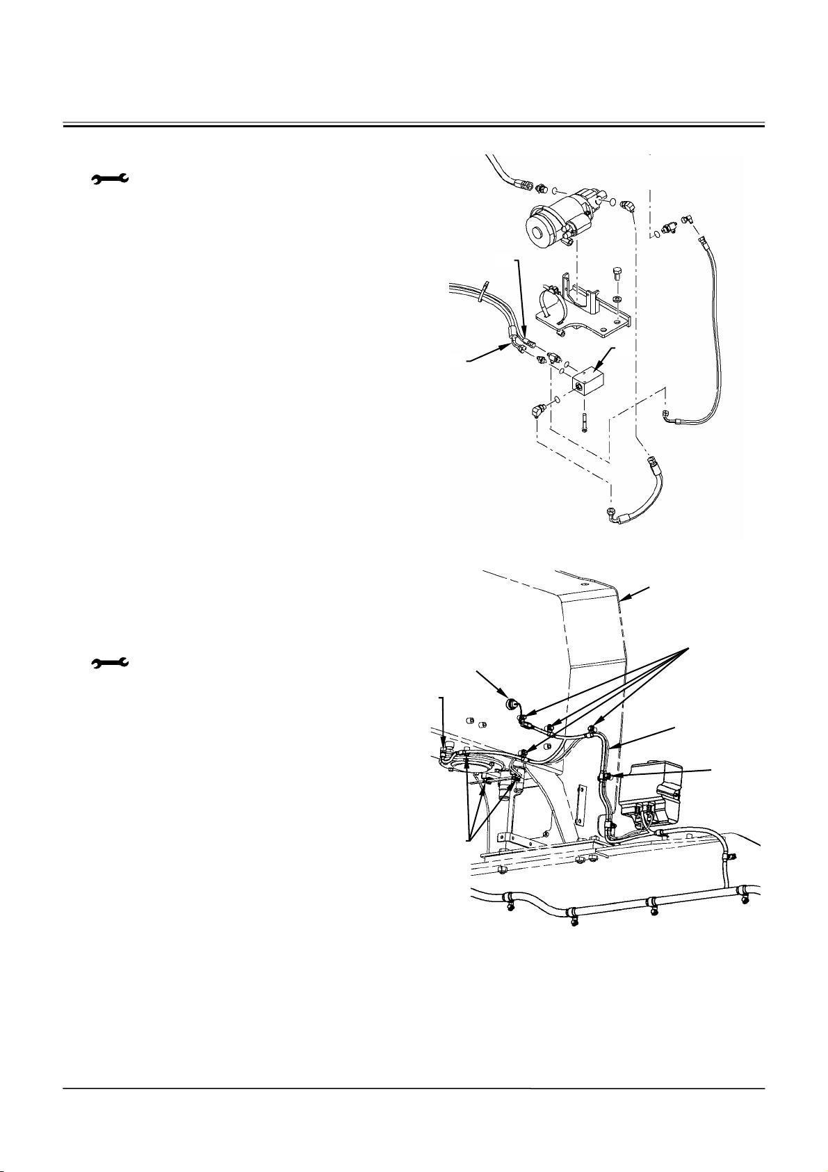
BODY (UPPERSTRUCTURE) / Hydraulic Oil Tank
11. Disconnect hoses (18, 19) from block (20) when
the emergency steering pump is installed.
: 17 mm, 22 mm
12. Disconnect the connector from hydraulic oil
temperature sensor (23) and level sensor (24).
13. Remove bolts (22) (8 used) from clamps (21) (8
used). Disconnect wire harness (25) from
hydraulic oil tank (5).
: 12 mm
18
20
19
W4GB-02-03-014
5
21, 22
24
23
21, 22
W2-5-3
25
21, 22
W4GB-02-03-017
Page 94
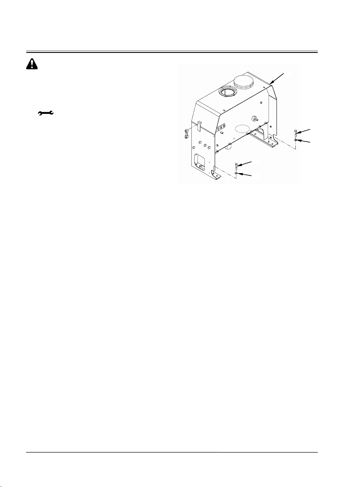
BODY (UPPERSTRUCTURE) / Hydraulic Oil Tank
CAUTION: Hydraulic oil tank (5) weight:
215 kg (475 lb)
14. Attach a nylon sling onto hydraulic oil tank (5).
Hoist and hold hydraulic oil tank (5). Remove bolts
(26) (6 used) and washers (27) (6 used) from
hydraulic oil tank (5).
: 24 mm
15. Hoist and remove hydraulic oil tank (5) from the
frame.
5
26
27
26
27
W4GB-02-03-016
W2-5-4
Page 95
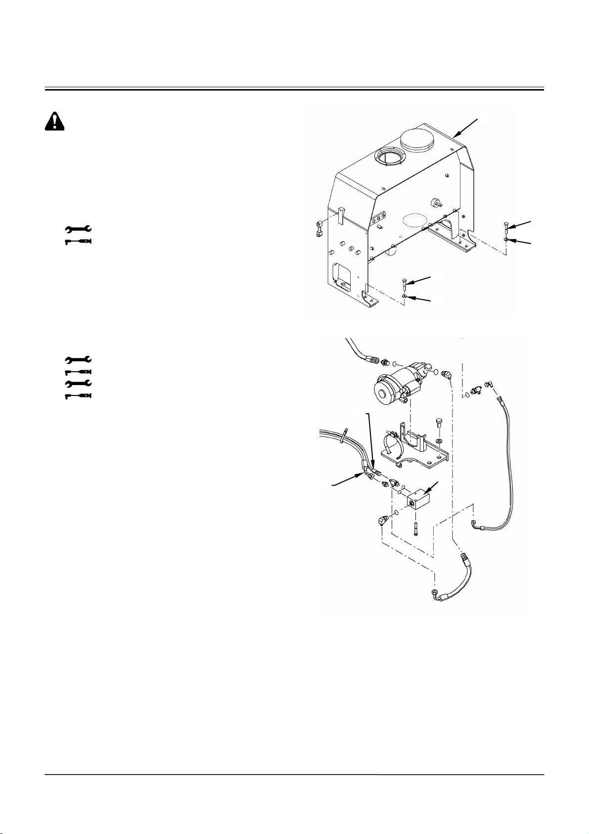
BODY (UPPERSTRUCTURE) / Hydraulic Oil Tank
Installation
CAUTION: Hydraulic oil tank (5) weight:
215 kg (475 lb)
1. Attach a nylon sling onto hydraulic oil tank (5).
Hoist and align hydraulic oil tank (5) with the
mounting position of the frame.
2. Install hydraulic oil tank (5) to the frame with bolts
(26) (6 used) and washers (27) (6 used).
: 24 mm
: 210 N⋅m (21.5 kgf⋅m, 152 lbf·ft)
3. Connect hoses (18, 19) to block (20) as shown in
the identification tag when the emergency steering
pump is installed.
: 17 mm
: 24.5 N⋅m (2.5 kgf⋅m, 18 lbf·ft)
: 22 mm
: 39 N⋅m (4 kgf⋅m, 28.5 lbf·ft)
5
26
27
26
27
W4GB-02-03-016
18
19
20
W4GB-02-03-014
W2-5-5
Page 96
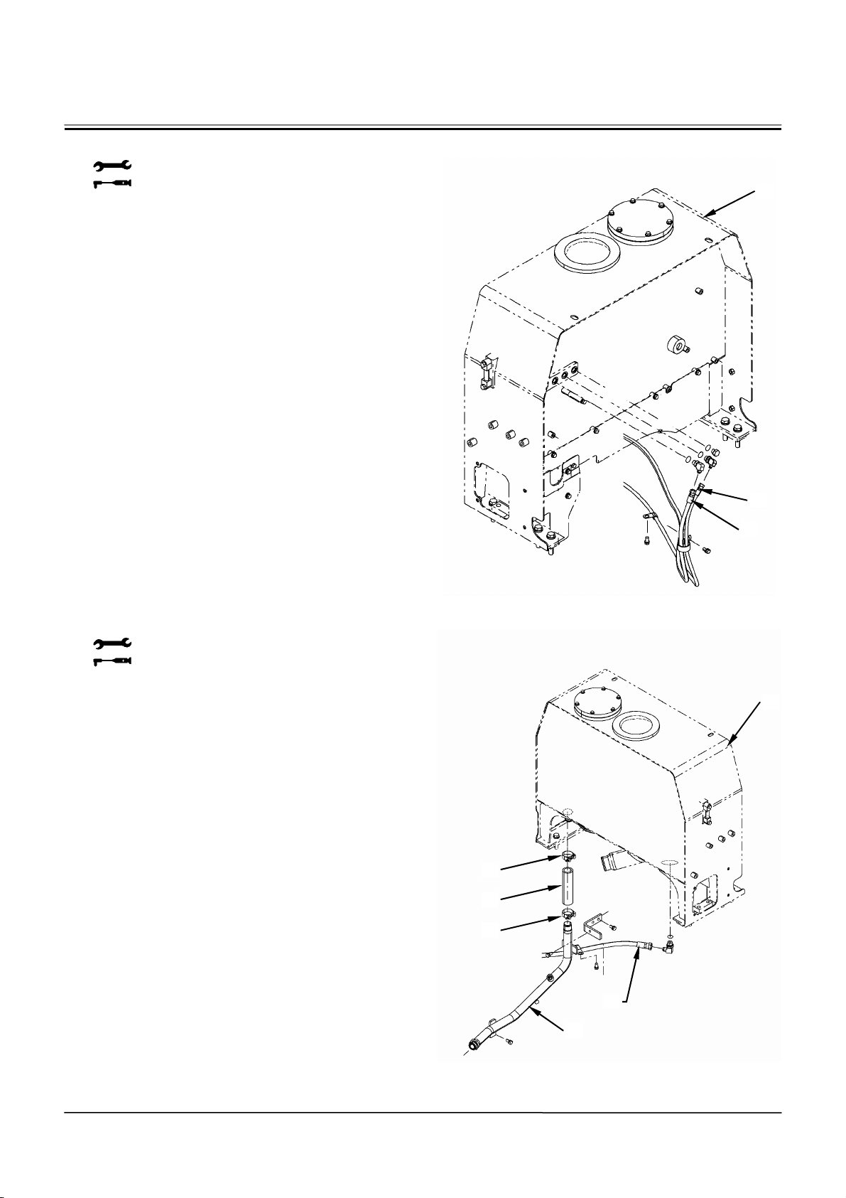
BODY (UPPERSTRUCTURE) / Hydraulic Oil Tank
4. Connect hoses (16, 17) to hydraulic oil tank (5).
: 17 mm
: 24.5 N⋅m (2.5 kgf⋅m, 18 lbf·ft)
5. Connect hose (14) to hydraulic oil tank (5).
: 27 mm
: 93 N⋅m (9.5 kgf⋅m, 68.5 lbf·ft)
6. Connect hose (13) to hydraulic oil tank (5) and
pipe (15). Secure hose (13) with hose clamps (12)
(2 used).
5
16
17
W4GB-02-03-013
5
W2-5-6
12
13
12
14
15
W4GB-02-03-012
Page 97
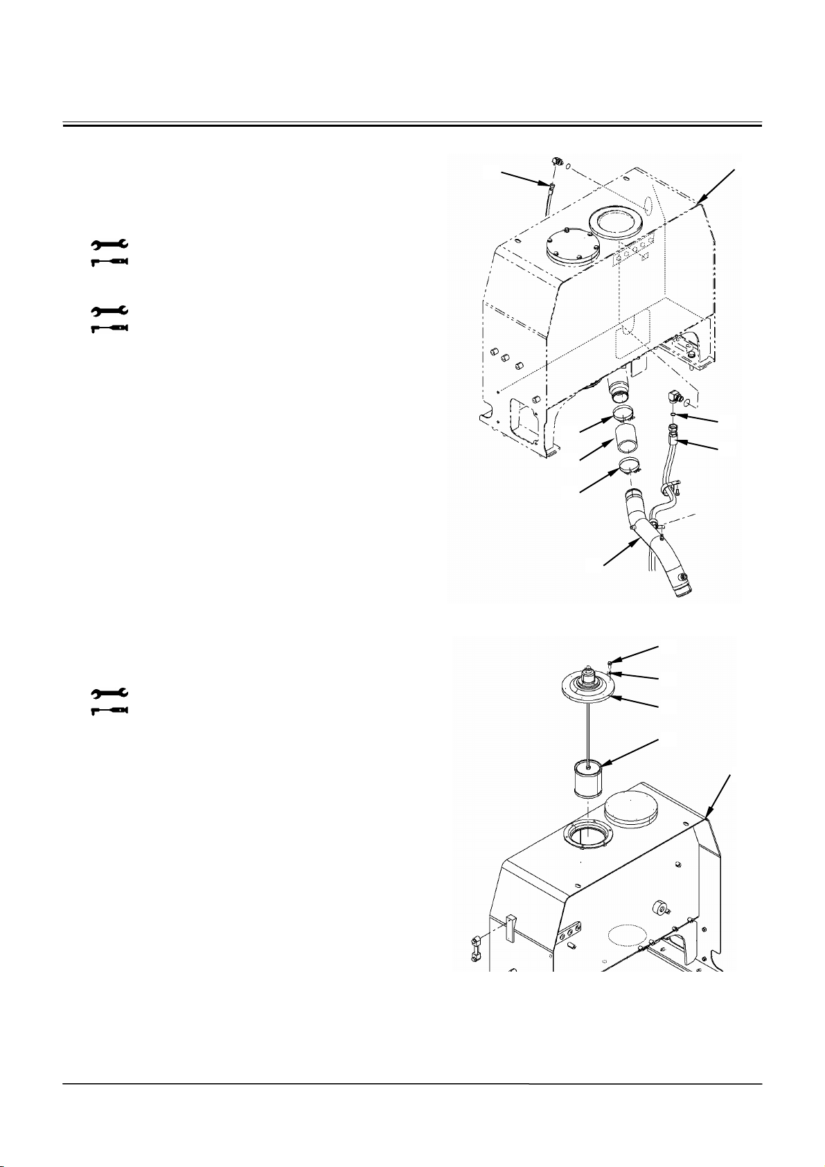
BODY (UPPERSTRUCTURE) / Hydraulic Oil Tank
7. Connect hose (10) to hydraulic oil tank (5) and
pipe (11). Secure hose (10) with hose clamps (9)
(2 used).
8. Install hydraulic oil tank (5) and new O-ring (7),
and connect hose (8).
: 36 mm
: 175 N⋅m (18 kgf⋅m, 129 lbf·ft)
9. Connect hose (6) to hydraulic oil tank (5).
: 22 mm
: 39 N⋅m (4 kgf⋅m, 28.5 lbf·ft)
10. Add hydraulic oil to hydraulic oil tank (5).
Hydraulic oil amount: 120 L (31.7 US gal.)
11. Install suction filter (4) to hydraulic oil tank (5).
12. Install cover (3) to hydraulic oil tank (5) with bolts
(1) (6 used) and washers (2) (6 used).
: 14 mm
: 20 N⋅m (2 kgf⋅m, 14.5 lbf·ft)
6
9
10
9
11
5
7
8
W4GB-02-03-011
1
2
3
4
W2-5-7
5
W4GB-02-03-010
Page 98

BODY (UPPERSTRUCTURE) / Hydraulic Oil Tank
13. Connect wire harness (25) to hydraulic oil tank (5)
with bolts (22) (8 used) and clamps (21) (8 used).
: 12 mm
: 20 N⋅m (2 kgf⋅m, 14.5 lbf·ft)
14. Connect the connectors of level sensor (24) and
hydraulic oil temperature sensor (23).
15. Install the left and right side fenders.
: 17 mm
: 50 N⋅m (5.1 kgf⋅m, 36 lbf·ft)
16. Install the hood. (Refer to W2-4-1.)
5
21, 22
24
23
25
21, 22
21, 22
W4GB-02-03-017
W2-5-8
Page 99
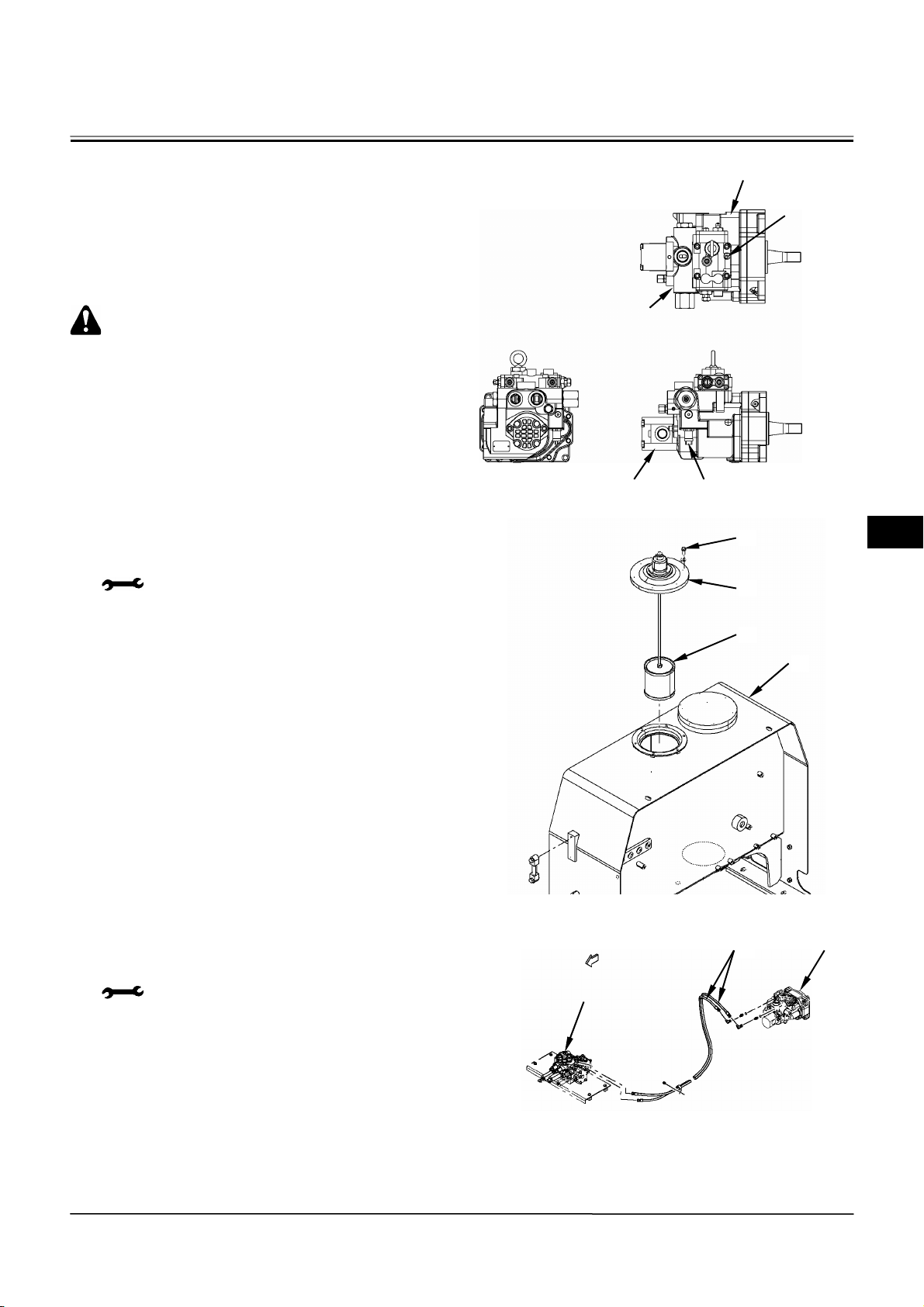
BODY (UPPERSTRUCTURE) / Pump Device
REMOVAL AND INSTALLATION OF PUMP DEVICE
Removal
1. Remove the cab with the cockpit attached.
(Refer to REMOVAL AND INSTALLATION OF
CAB in W2-1.)
CAUTION: Pump device weight:
108 kg (240 lb)
2. Remove sems bolts (1) (6 used) from hydraulic oil
tank (4). Remove cover (2) and suction filter (3)
from hydraulic oil tank (4). Drain hydraulic oil.
: 14 mm
3. Disconnect hoses (5) (2 used) from main pump
(6). Cap the open ends. Attach an identification
tag onto the disconnected hoses for assembling.
: 19 mm, 22 mm
Main Pump
Priority Valve
Regulator
Pilot Pump
Pump Delivery
Pressure Switch
T4GB-01-02-009
1
2
3
4
W4GB-02-03-010
Control Valve
5
6
W2-6-1
W4GB-02-04-012
Page 100
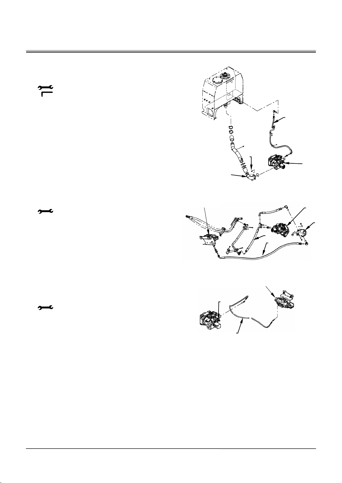
BODY (UPPERSTRUCTURE) / Pump Device
4. Disconnect hose (7) from main pump (6). Cap the
open ends. Remove socket bolts (8) (4 used)
from pipe (9). Disconnect pipe (9) from main
pump (6).
: 32 mm, 36 mm
: 10 mm
5. Disconnect hose (11) from main pump (6).
Disconnect hose (12) from priority valve (10). Cap
the open ends.
: 36 mm, 41 mm
6. Disconnect hose (13) from priority valve (10). Cap
the open ends.
: 14 mm, 17 mm
Steering Valve
7
8
6
9
W4GB-02-04-019
6
10
11
12
W4GB-02-04-014
Steering Valve
10
W2-6-2
13
W4GB-02-04-015
 Loading...