

Page 1

WJ200
Series Inverter
Quick Reference Guide
• Single-phase Input 200V class
• Three-phase Input 200V class
• Three-phase Input 400V class
Manual Number: NT3251X
May 2010
Hitachi Industrial Equipment Systems Co., Ltd.
Refer to the user manual for detail
Page 2

Page 3

UL Cautions, Warnings and Instructions xii
Warnings and Cautions for Troubleshooting and Maintenance
The warnings and instructions in this section summarizes the procedures necessary to ensure an
inverter installation complies with Underwriters Laboratories
WARNING: Use 60/75C Cu wire only. (for models: WJ200-001L, 002L, 004L, 007L, 015S, 022S,
004H, 007H, 015H, 022H, 030H)
WARNING: Use 75C Cu wire only. (for models: WJ200-001S, -002S, -004S, -007S, -015L, -022L,
-037L, -055L, -075L, -110L, -150L, -040H, -055H, -075H, -110H and -150H)
WARNING: Suitable for use on a circuit capable of delivering not more than 100,000 rms
Symmetrical Amperes, 240 or 480V maximum.
WARNING: When protected by CC, G, J, or R class Fuses, or when Protected By A Circuit Breaker
Having An Interrupting Rating Not Less Than 100,000 rms Symmetrical Amperes, 240 or 480 Volts
Maximum.
WARNING: Install device in pollution degree 2 environment.
WARNING: Maximum Surrounding Air Temperature 50C
WARNING: Solid state motor overload protection is provided in each model
WARNING: Integral solid state short circuit protection does not provide branch circuit protection.
Branch circuit protection must be provided in accordance with the National Electric Code and any
additional local codes
guidelines.
1
Page 4

Terminal symbols and Screw size
Inverter Model Screw Size
WJ200-001S
WJ200-002S
M3.5 1.0 AWG16 (1.3mm
Required
Torque (N-m)
Wire range
2
)
WJ200-004S
WJ200-007S M4 1.4 AWG12 (3.3mm2)
WJ200-015S
WJ200-022S
M4 1.4 AWG10 (5.3mm
2
)
WJ200-001L
WJ200-002L
WJ200-004L
M3.5 1.0 AWG16 (1.3mm
2
)
WJ200-007L
WJ200-015L M4 1.4 AWG14 (2.1mm2)
WJ200-022L M4 1.4 AWG12 (3.3mm2)
WJ200-037L M4 1.4 AWG10 (5.3mm2)
WJ200-055L
WJ200-075L
M5 3.0 AWG6 (13mm
2
)
WJ200-110L M6 3.9 to 5.1 AWG4 (21mm2)
WJ200-150L M8 5.9 to 8.8 AWG2 (34mm2)
WJ200-004H
WJ200-007H
M4 1.4 AWG16 (1.3mm
2
)
WJ200-015H
WJ200-022H
WJ200-030H
M4 1.4 AWG14 (2.1mm
2
)
WJ200-040H M4 1.4 AWG12 (3.3mm2)
WJ200-055H
WJ200-075H
WJ200-110H
WJ200-150H
M5 3.0 AWG10 (5.3mm
M6 3.9 to 5.1 AWG6 (13mm
2
)
2
)
2
Page 5

Fuse Sizes
The inverter shall be connected with a UL Listed Cartridge Nonrenewable fuse, rated
600Vac with the current ratings as shown in the table below.
Inverter Model Type Rating
WJ200-001S
WJ200-002S
WJ200-004S
WJ200-007S 15A, AIC 200kA
WJ200-015S
WJ200-022S
WJ200-001L
WJ200-002L
WJ200-004L
WJ200-007L
WJ200-015L
WJ200-022L 20A, AIC 200kA
WJ200-037L 30A, AIC 200kA
WJ200-055L
WJ200-075L
WJ200-110L
WJ200-150L
WJ200-004H
WJ200-007H
WJ200-015H
WJ200-022H
WJ200-030H
WJ200-040H
WJ200-055H
WJ200-075H
WJ200-110H
WJ200-150H
Class J
10A, AIC 200kA
30A, AIC 200kA
10A, AIC 200kA
15A, AIC 200kA
40A, AIC 200kA
80A, AIC 200kA
10A, AIC 200kA
15A, AIC 200kA
20A, AIC 200kA
40A, AIC 200kA
3
Page 6
A
_
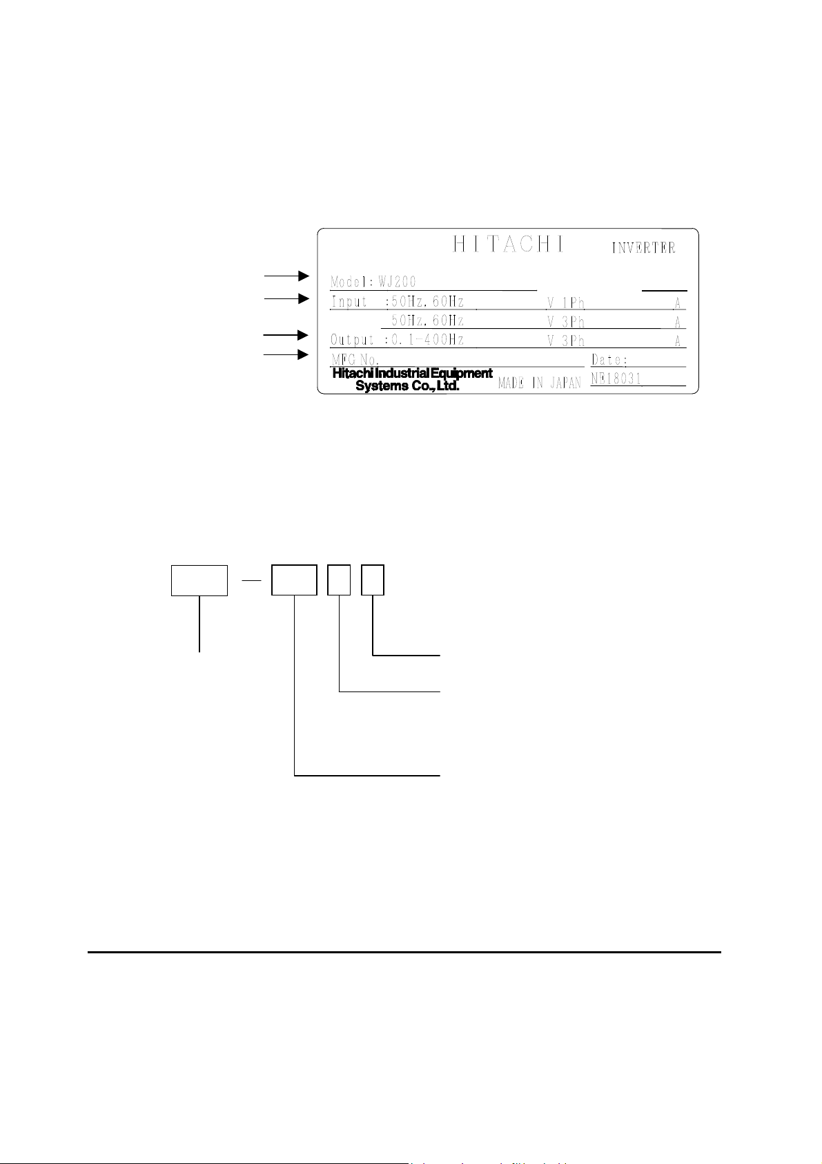
Inverter Specification Label
The Hitachi WJ200 inverters have product labels located on the right side of the housing,
as pictured below. Be sure to verify that the specifications on the labels match your power
source, and application safety requirements.
Model name
Input ratings
Output ratings
MFG number
Inverter Specification Label
05A
-001SF
200-240
200-240
T12345_A_-001
Ver:2.0
2.0/1.3
1.2 /1. 0
1005
The model number for a specific inverter contains useful information about its operating
characteristics. Refer to the model number legend below:
WJ200
Series name
001 S F
Configuration type
F=with keypad
Input voltage:
S=Single-phase 200V class
L=Three-phase 200V class
H=Three-phase 400V class
pplicable motor capacity in kW
001=0.1kW 037=3.7kW
002=0.2kW 040=4.0kW
004=0.4kW 055=5.5kW
007=0.75kW 075=7.5kW
015=1.5kW 110=11kW
022=2.2kW 150=15kW
030=3.0kW
4
Page 7

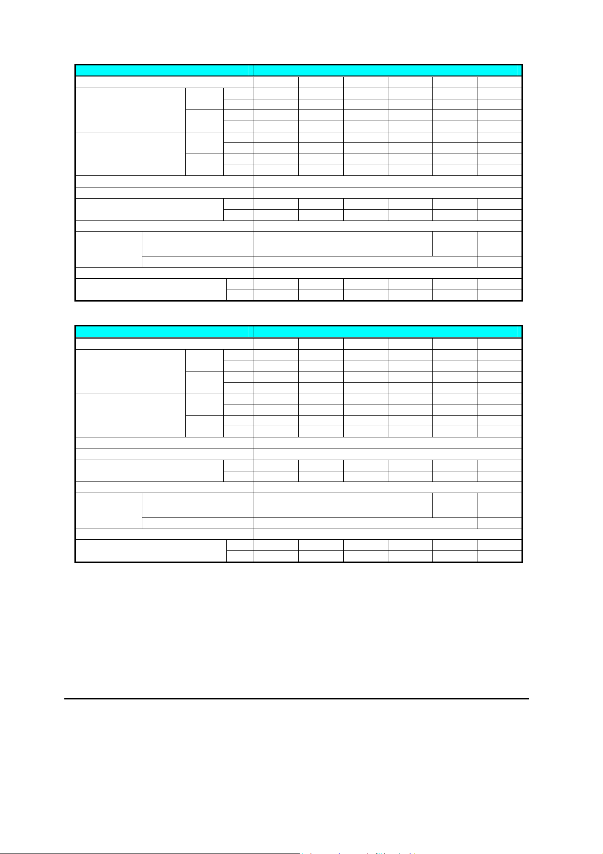
WJ200 Inverter Specifications
Model-specific tables for 200V and 400V class inverters
The following tables are specific to WJ200 inverters for the 200V and 400V class model
groups. Note that “General Specifications” on page in this chapter
class groups. Footnotes for all specification tables follow the table below.
Item Single-phase 200V class Specifications
WJ200 inverters, 200V models 001SF 002SF 004SF 007SF 015SF 022SF
Applicable motor size
*2
HP
Rated capacity (kVA)
240V
Rated input voltage
Rated output voltage *3 3-phase: 200 to 240V (proportional to input voltage)
Starting torque *6 200% at 0.5Hz
Braking
DC braking Variable operating frequency, time, and braking force
Without resistor
With resistor 150% 100%
VT 0.2 0.4 0.55 1.1 2.2 3.0 kW
CT 0.1 0.2 0.4 0.75 1.5 2.2
VT
CT
VT 0.4 0.6 1.2 2.0 3.3 4.1 200V
CT 0.2 0.5 1.0 1.7 2.7 3.8
VT 0.4 0.7 1.4 2.4 3.9 4.9
CT 0.3 0.6 1.2 2.0 3.3 4.5
VT 1.2 1.9 3.5 6.0 9.6 12.0 Rated output current (A)
CT 1.0 1.6 3.0 5.0 8.0 11.0
kg 1.0 1.0 1.1 1.6 1.8 1.8 Weight
lb 2.2 2.2 2.4 3.5 4.0 4.0
1/4 1/2 3/4 1.5 3 4
1/8 1/4 1/2 1 2 3
Single-phase: 200V-15% to 240V +10%, 50/60Hz 5%
100%:
50%:
50Hz
60Hz
apply to both voltage
70%:50Hz
50%:
60Hz
20%:50Hz
20%:
60Hz
5
Page 8

WJ200 Inverter Specifications, continued…
Item Three-phase 200V class Specifications
WJ200 inverters, 200V models
Applicable motor size *2
HP
Rated capacity (kVA)
240V
Rated input voltage
Rated output voltage *3 Three-phase: 200 to 240V (proportional to input voltage)
Starting torque *6 200% at 0.5Hz
Braking
DC braking Variable operating frequency, time, and braking force
Without resistor
With resistor 150% 100%
VT 0.2 0.4 0.75 1.1 2.2 3.0 kW
CT 0.1 0.2 0.4 0.75 1.5 2.2
VT
CT
VT 0.4 0.6 1.2 2.0 3.3 4.1 200V
CT 0.2 0.5 1.0 1.7 2.7 3.8
VT 0.4 0.7 1.4 2.4 3.9 4.9
CT 0.3 0.6 1.2 2.0 3.3 4.5
VT 1.2 1.9 3.5 6.0 9.6 12.0 Rated output current (A)
CT 1.0 1.6 3.0 5.0 8.0 11.0
kg 1.0 1.0 1.1 1.2 1.6 1.8 Weight
lb 2.2 2.2 2.4 2.6 3.5 4.0
Item Three-phase 200V class Specifications
WJ200 inverters, 200V models
Applicable motor size *2
HP
Rated capacity (kVA)
240V
Rated input voltage
Rated output voltage *3 3-phase: 200 to 240V (proportional to input voltage)
Starting torque *6 200% at 0.5Hz
Without resistor
With resistor 150%
DC braking Variable operating frequency, time, and braking force
VT 5.5 7.5 11 15 18.5 kW
CT 3.7 5.5 7.5 11 15
VT
CT
VT 6.7 10.3 13.8 19.3 20.7 200V
CT 6.0 8.6 11.4 16.2 20.7
VT 8.1 12.4 16.6 23.2 24.9
CT 7.2 10.3 13.7 19.5 24.9
VT 19.6 30.0 40.0 56.0 69.0 Rated output current (A)
CT 17.5 25.0 33.0 47.0 60.0
Kg 2.0 3.3 3.4 5.1 7.4 Weight
lb 4.4 7.3 7.5 11.2 16.3
001LF 002LF 004LF 007LF 015LF 022LF
1/4 1/2 1 1.5 3 4
1/8 1/4 1/2 1 2 3
Three-phase: 200V-15% to 240V +10%, 50/60Hz 5%
60Hz
60Hz
20%:
20%:
100%:
50%:
037LF 055LF 075LF 110LF 150LF
7.5 10 15 20 25
5 7.5 10 15 20
Single-phase: 200V-15% to 240V +10%, 50/60Hz 5%
100%:
50%:
50Hz
60Hz
50Hz
60Hz
70%:50Hz
50%:
70%:50Hz
50%:
Braking
50Hz
60Hz
6
Page 9
WJ200 Inverter Specifications, continued…
Item Three-phase 400V class Specifications
WJ200 inverters, 400V models
Applicable motor size *2
HP
Rated capacity (kVA)
480V
Rated input voltage
Rated output voltage *3 Three-phase: 200 to 240V (proportional to input voltage)
Starting torque *6 200% at 0.5Hz
Without resistor
With resistor 150%
DC braking Variable operating frequency, time, and braking force
VT 0.75 1.5 2.2 3.0 4.0 5.5 kW
CT 0.4 0.75 1.5 2.2 3.0 4.0
VT 1 2 3 4 5 7.5
CT 1/2 1 2 3 4 5
VT 1.3 2.6 3.5 4.5 5.7 7.3 380V
CT 1.1 2.2 3.1 3.6 4.7 6.0
VT 1.7 3.4 4.4 5.7 7.3 9.2
CT 1.4 2.8 3.9 4.5 5.9 7.6
VT 2.1 4.1 5.4 6.9 8.8 11.1 Rated output current (A)
CT 1.8 3.4 4.8 5.5 7.2 9.2
kg 1.5 1.6 1.8 1.9 1.9 2.1 Weight
lb 3.3 3.5 4.0 4.2 4.2 4.6
Item Three-phase 400V class Specifications
WJ200 inverters, 400V models
Applicable motor size *2
HP
Rated capacity (kVA)
480V
Rated input voltage
Rated output voltage *3 3-phase: 200 to 240V (proportional to input voltage)
Starting torque *6 200% at 0.5Hz
Without resistor
With resistor 150%
DC braking Variable operating frequency, time, and braking force
VT 7.5 11 15 18.5 kW
CT 5.5 7.5 11 15
VT 10 15 20 25
CT 7.5 10 15 20
VT 11.5 15.1 20.4 25.0 380V
CT 9.7 11.8 15.7 20.4
VT 14.5 19.1 25.7 31.5
CT 12.3 14.9 19.9 25.7
VT 17.5 23.0 31.0 38.0 Rated output current (A)
CT 14.8 18.0 24.0 31.0
kg 3.5 3.5 4.7 5.2 Weight
lb 7.7 7.7 10.4 11.5
004HF 007HF 015HF 022HF 030HF 040HF
Three-phase: 200V-15% to 240V +10%, 50/60Hz 5%
100%:
50%:
055HF 075HF 110HF 150HF
Single-phase: 200V-15% to 240V +10%, 50/60Hz 5%
100%:
50%:
50Hz
60Hz
50Hz
60Hz
70%:50Hz
60Hz
50%:
Braking
Braking
7
Page 10

The following table shows which models need derating.
1-ph 200V class Need
derating
WJ200-001S
WJ200-002S
WJ200-004S
WJ200-007S
WJ200-015S
WJ200-022S
− −
− −
− −
− −
− −
9:need derating
−:need no derating
−
−
9
9
−
−
Use the following derating curves to help determine the optimal carrier frequency setting
for your inverter and find the output current derating. Be sure to use the proper curve for
your particular WJ200 inverter model number.
3-ph 200V class Need
derating
WJ200-001L
WJ200-002L
WJ200-004L
WJ200-007L
WJ200-015L
WJ200-022L
WJ200-037L
WJ200-055L
WJ200-075L
WJ200-110L
WJ200-150L
−
9
9
−
−
−
9
−
9
9
9
3-ph 400V class Need
derating
WJ200-004H
WJ200-007H
WJ200-015H
WJ200-022H
WJ200-030H
WJ200-040H
WJ200-055H
WJ200-075H
WJ200-110H
WJ200-150H
− −
9
9
−
−
−
9
−
9
9
9
8
Page 11
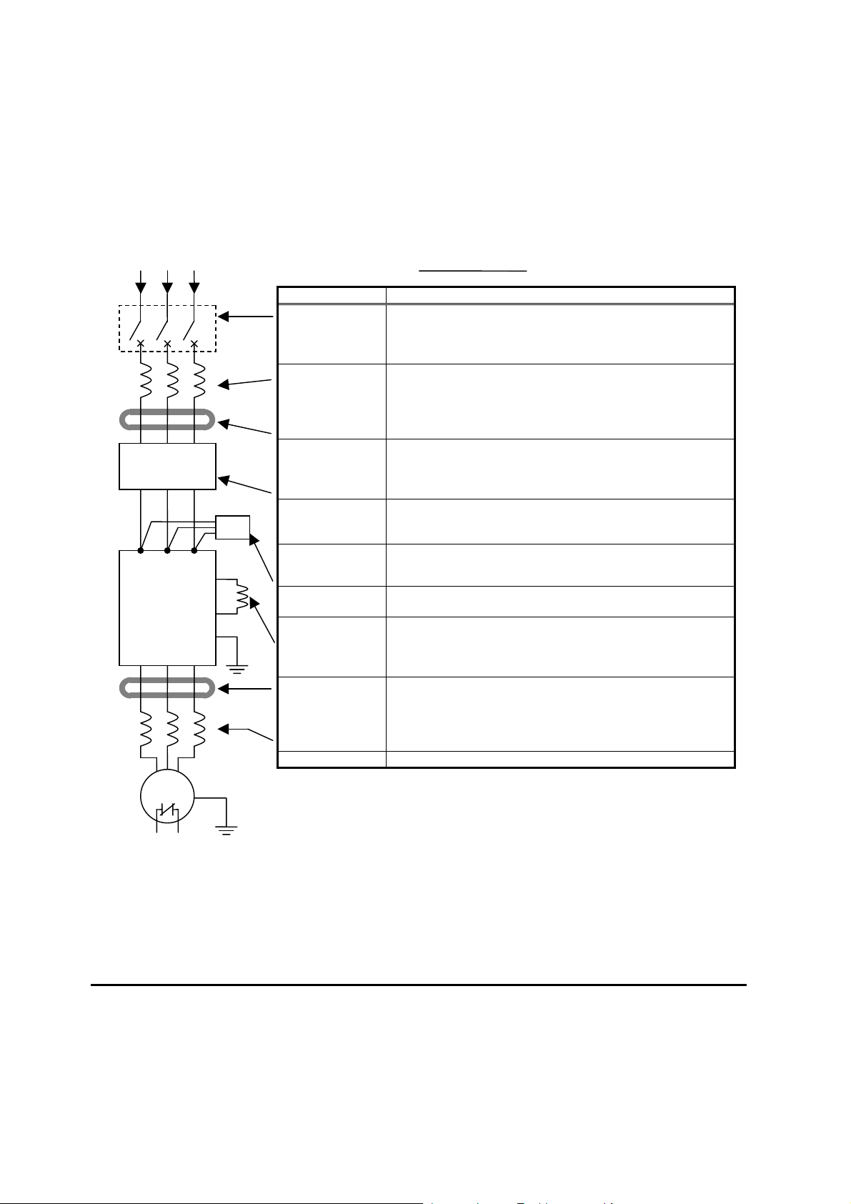
Basic System Description
A motor control system will obviously include a motor and inverter, as well as a circuit
breaker or fuses for safety. If you are connecting a motor to the inverter on a test bench
just to get started, that’s all you may need for now. But a system can also have a variety of
additional components. Some can be for noise suppression, while others may enhance the
inverter’s braking performance. The figure and table below show a system with all the
optional components you might need in your finished application.
L1 L2 L3
+1
Inverter
GND
T1 T2 T3
Breaker,
MCCB or
GFI
+
From power supply
Name Function
Breaker /
disconnect
Input-side
AC Reactor
Radio noise filter
EMC filter (for
CE applications,
see Appendix D)
Radio noise filter
(use in non-CE
applications)
DC link choke
Radio noise filter
Output-side
AC Reactor
LCR filter
A molded-case circuit breaker (MCCB), ground fault
interrupter (GFI), or a fused disconnect device. NOTE: The
installer must refer to the NEC and local codes to ensure
safety and compliance.
This is useful in suppressing harmonics induced on the
power supply lines and for improving the power factor.
WARNING: Some applications must use an input-side AC
Reactor to prevent inverter damage. See Warning on next
page.
Electrical noise interference may occur on nearby
equipment such as a radio receiver. This magnetic choke
filter helps reduce radiated noise (can also be used on
output).
Reduces the conducted noise on the power supply wiring
between the inverter and the power distribution system.
Connect to the inverter primary (input) side.
This capacitive filter reduces radiated noise from the main
power wires in the inverter input side.
Suppress harmonics generated by the inverter. However, it
will not protect the input diode bridge rectifier.
Electrical noise interference may occur on nearby
equipment such as a radio receiver. This magnetic choke
filter helps reduce radiated noise (can also be used on
input).
This reactor reduces the vibration in the motor caused by
the inverter’s switching waveforms, by smoothing the
waveform to approximate commercial power quality. It is
also useful to reduce harmonics when wiring from the
inverter to the motor is more than 10m in length.
Sine wave shaping filter for output side.
Motor
Thermal
switch
9
Page 12

Determining Wire and Fuse Sizes
The maximum motor currents in your application determines the recommended wore size.
The following table gives the wire size in AWG. The “Power Lines” column applies to the
inverter input power, output wires to the motor, the earth ground connection, and any other
components shown in the “Basic System Description” on page 2-7. The “Signal Lines”
column applies to any wire connecting to the two green connectors just inside the front
cover panel.
Motor Output Wiring
kW HP
VT CT VT CT
0.2 0.1 ¼ 1/8
0.4 0.2 ½ ¼
0.55
0.4 ¾ ½
1.1
0.75
1.5 1
2.2 1.5 3 2
3.0 2.2 4 3
0.2 0.1 ¼ 1/8
0.4 0.2 ½ ¼
0.75
0.4 1 ½
1.1
0.75
1.5 1
2.2 1.5 3 2
3.0 2.2 4 3
5.5 3.7 7.5 5
7.5 5.5 10 7.5
11 7.5 15 10
15 11 20 15
18.5
15 25 20
0.75
0.4 1 ½
1.5
0.75
2 1
2.2 1.5 3 2
3.0 2.2 4 3
4.0 3.0 5 4
5.5 4.0 7.5 5
7.5 5.5 10 7.5
11 7.5 15 10
15 11 20 15
18.5
15 25 20
Note 1: Field wiring must be made by a UL-Listed and CSA-certified closed-loop terminal
Note 2: Be sure to consider the capacity of the circuit breaker to be used.
Note 3: Be sure to use a larger wire gauge if power line length exceeds 66ft. (20m).
Note 4: Use 18 AWG / 0.75mm
Inverter Model
Power Lines Signal Lines
WJ200-001SF
WJ200-002SF
WJ200-004SF
WJ200-007SF
WJ200-015SF
WJ200-022SF
AWG16 / 1.3mm
(75C only)
AWG12 / 3.3mm
(75C only)
AWG10 / 5.3mm
WJ200-001LF
WJ200-002LF
WJ200-004LF
AWG16 / 1.3mm
WJ200-007LF
WJ200-015LF
WJ200-022LF
WJ200-037LF
WJ200-055LF
WJ200-075LF
WJ200-110LF
WJ200-150LF
AWG14 / 2.1mm
(75C only)
AWG12 / 3.3mm
(75C only)
AWG10 / 5.3mm
(75C only)
AWG6 / 13mm
(75C only)
AWG4 / 21mm
(75C only)
AWG2 / 34mm
(75C only)
WJ200-004HF
WJ200-007HF
AWG16 / 1.3mm
WJ200-015HF
WJ200-022HF
WJ200-030HF
WJ200-040HF
WJ200-055HF
WJ200-075HF
WJ200-110HF
WJ200-150HF
AWG14 / 2.1mm
AWG12 / 3.3mm
(75C only)
AWG10/ 5.3mm
(75C only)
AWG6 / 13mm
(75C only)
AWG6 / 13mm
(75C only)
connector sized for the wire gauge involved. Connector must be fixed by using
the crimping tool specified by the connector manufacturer.
2
wire for the alarm signal wire ([AL0], [AL1], [AL2]
terminals).
Applicable
equipment
Fuse (UL-rated,
class J, 600V ,
Maximum
allowable current)
2
10A
2
20A
2
30A
2
2
2
10A
15A
20A
2
30A
60A
80A
2
2
2
18 to 28
AWG / 0.14
to 0.75 mm2
shielded wire
(see Note 4)
80A
2
2
2
2
2
2
10A
15A
30A
50A
50A
10
Page 13
RB
-
RB
-
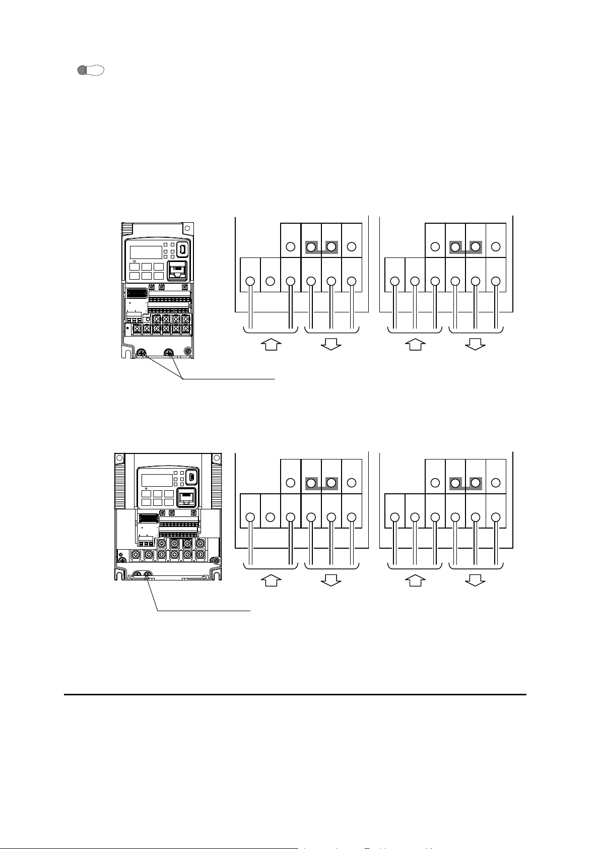
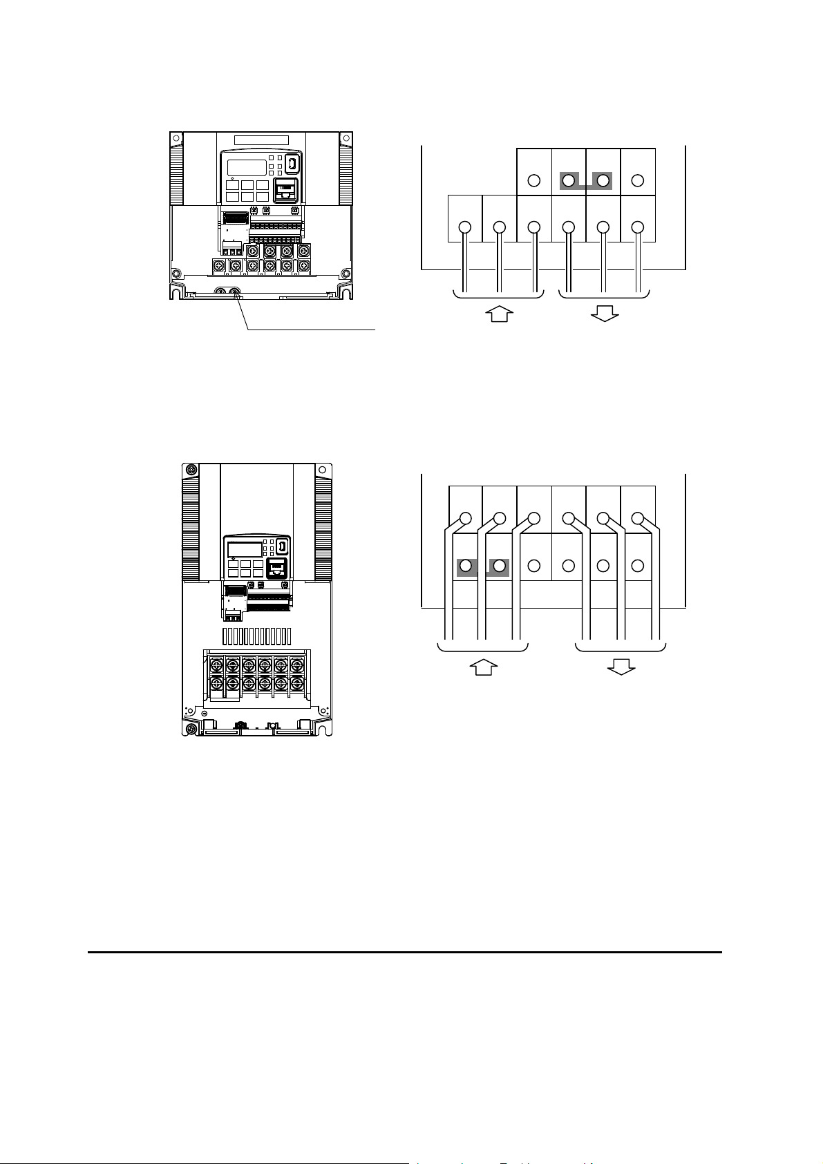
Wire the Inverter Input to a Supply
Step 6: In this step, you will connect wiring to the input of the inverter. First, you must
6
determine whether the inverter model you have required three-phase power only, or
single-phase power only. All models have the same power connection terminals [R/L1],
[S/L2], and [T/L3]. So you must refer to the specifications label (on the side of the
inverter) for the acceptable power source types! For inverters that can accept
single-phase power and are connected that way, terminal [S/L2] will remain
unconnected.
Note the use of ring lug connectors for a secure connection.
Single-phase 200V 0.1 to 0.4kW
Three-phase 200V 0.1 to 0.75kW
L1
Single-phase 200V 0.75 to 2.2kW
Three-phase 200V 1.5, 2.2kW
Three-phase 400V 0.4 to 3.0kW
Chassis Ground (M4)
Chassis Ground (M4)
N U/T1 V/T2 W/T3
Power input Output to Motor
L1
Power input Output to Motor
Single-phase Three-phase
+1
+
R/L1
S/L2 T/L3 U/T1 V/T2 W/T3
Power input Output to Motor
Single-phase Three-phase
+1
+
N U/T1 V/T2 W/T3
R/L1
S/L2 T/L3 U/T1 V/T2 W/T3
Power input Output to Motor
RB
RB
PD/+1
PD/+1
P/+ N/
P/+ N/
-
-
11
Page 14
Three-phase 200V 3.7kW
Three-phase 400V 4.0kW
PD/+1
P/+
N/-
W/T3 V/T2 U/T1
W/T3 V/T2 U/T1
G G RB
S/L2
S/L2
P/+
RB
T/L3
T/L3
N/
-
Chassis Ground (M4)
Three-phase 200V 5.5, 7.5kW
Three-phase 400V 5.5, 7.5kW
R/L1
Power input Output to Motor
R/L1
PD/+1
Power input Output to Motor
12
Page 15
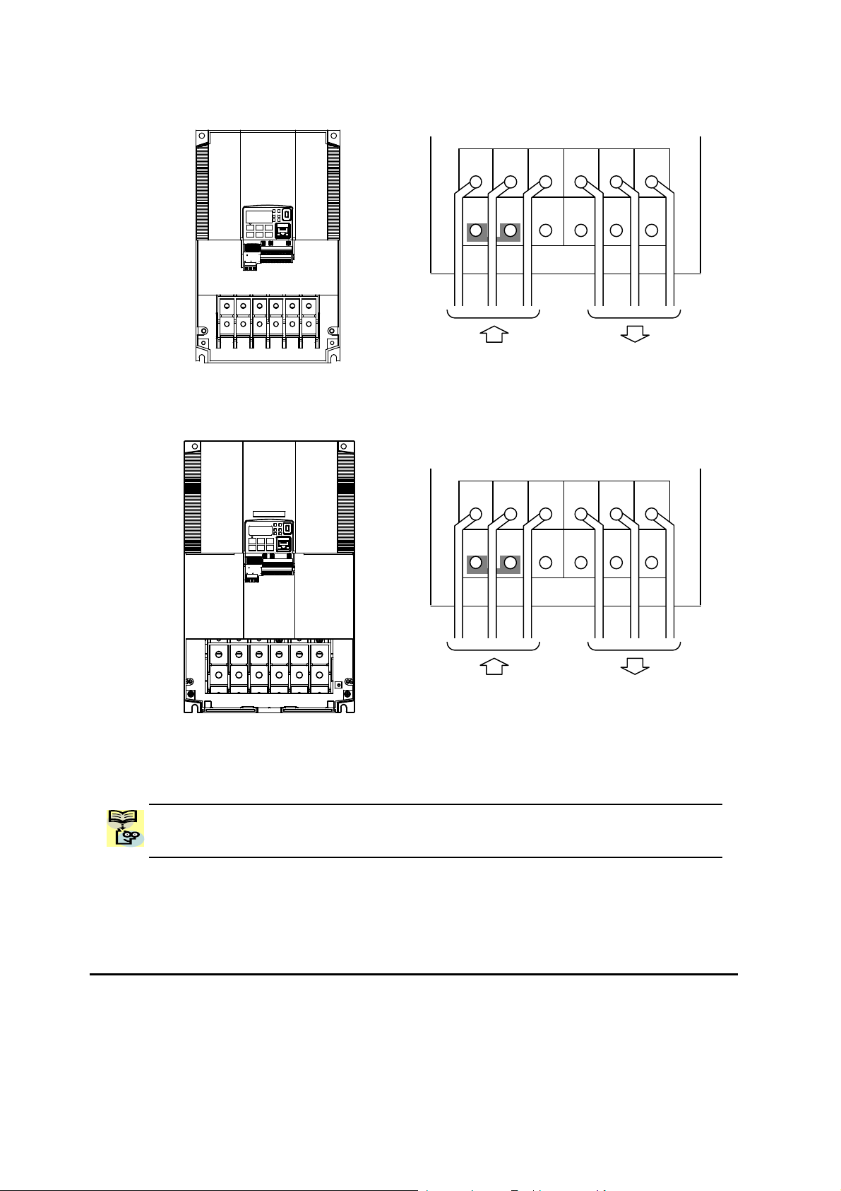
Three-phase 200V 11kW
Three-phase 400V 11, 15kW
Three-phase 200V 15kW
NOTE: An inverter powered by a portable power generator may receive a distorted power
waveform, overheating the generator. In general, the generator capacity should be five
times that of the inverter (kVA).
R/L1
PD/+1
Power input Output to Motor
R/L1
PD/+1
Power input Output to Motor
S/L2
P/+
S/L2
P/+
T/L3
N/
T/L3
N/
-
-
W/T3 V/T2 U/T1
G G RB
W/T3 V/T2 U/T1
G G RB
13
Page 16
Hz A
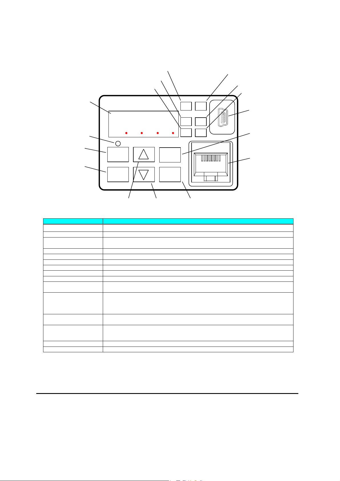
Using the Front Panel Keypad
Please take a moment to familiarize yourself with the keypad layout shown in the figure
below. The display is used in programming the inverter’s parameters, as well as monitoring
specific parameter values during operation.
(5) Monitor LED [Hz]
(4) RUN LED
(8) 7-seg LED
(6) Monitor LED [A]
RUN
PWR
(7) Run command LED
(9) RUN key
(11) Escape key
8888
RUN
1
STOP/
RESET
ALM
PRG
ESC
2
SET
(13) Down key (12) Up key
(14) Set key
Key and Indicator Legend
Items Contents
(1) POWER LED Turns ON (Green) while the inverter is powered up.
(2) ALARM LED Turns ON (Red) when the inverter trips.
(3) Program LED
(4) RUN LED Turns ON (Green) when the inverter is driving the motor.
(5) Monitor LED [Hz] Turns ON (Green) when the displayed data is frequency related.
(6) Monitor LED [A] Turns ON (Green) when the displayed data is current related.
(7) Run command LED Turns ON (Green) when a Run command is set to the operator. (Run key is effective.)
(8) 7-seg LED Shows each parameter, monitors etc.
(9) Run key Makes inverter run.
(10) Stop/reset key
(11) ESC key
(12) Up key
(13) Down key
(14) SET key
(15) USB connector Connect USB connector (mini-B) for using PC communication
(16) RJ45 connector Connect RJ45 jack for remote operator
¾ Turns ON (Green) when the display shows changeable parameter.
¾ Blinks when there is a mismatch in setting.
¾ Makes inverter decelerates to a stop.
¾ Reset the inverter when it is in trip situation
¾ Go to the top of next function group, when a function mode is shown
¾ Cancel the setting and return to the function code, when a data is shown
¾ Moves the cursor to a digit left, when it is in digit-to-digit setting mode
¾ Pressing for 1 second leads to display data of d001, regardless of current display.
¾ Increase or decrease the data.
¾ Pressing the both keys at the same time gives you the digit-to-digit edit.
¾ Go to the data display mode when a function code is shown
¾ Stores the data and go back to show the function code, when data is shown.
¾ Moves the cursor to a digit right, when it is in digit-to-digit display mode
(1) POWER LED
(2) ALARM LED
(3) Program LED
(15) USB connector
(10) Stop/reset key
(16) RJ45 connector
14
Page 17
Keys, Modes, and Parameters
The purpose of the keypad is to provide a way to
change modes and parameters. The term function
applies to both monitoring modes and parameters.
These are all accessible through function codes that are
primary 4-character codes. The various functions are
separated into related groups identifiable by the
left-most character, as the table shows.
Function
Group
“D” Monitoring functions Monitor
“F” Main profile parameters
“A” Standard functions
“B” Fine tuning functions
“C” Intelligent terminal functions
“H” Motor constant related functions
“P” Pulse train input, torque, EzSQ, and
“U” User selected parameters
“E” Error codes
Type (Category) of Function Mode to Access
communication related functions
You can see from the following page how to monitor and/or program the parameters.
Keypad Navigation Map
8888
RUN
ESC
Program
Program
Program
Program
Program
Program
Program
STOP/
1
RESET
2
SET
PRG LED
Indicator
z
z
z
z
z
z
z
RUN
Hz
A
PWR
ALM
PRG
The WJ200 Series inverter drives have many programmable functions and parameters.
Chapter 3 will cover these in detail, but you need to access just a few items to perform the
powerup test. The menu structure makes use of function codes and parameter codes to
allow programming and monitoring with only a 4-digit display and keys and LEDs. So, it is
important to become familiar with the basic navigation map of parameters and functions in
the diagram below. You may later use this map as a reference.
15
Page 18
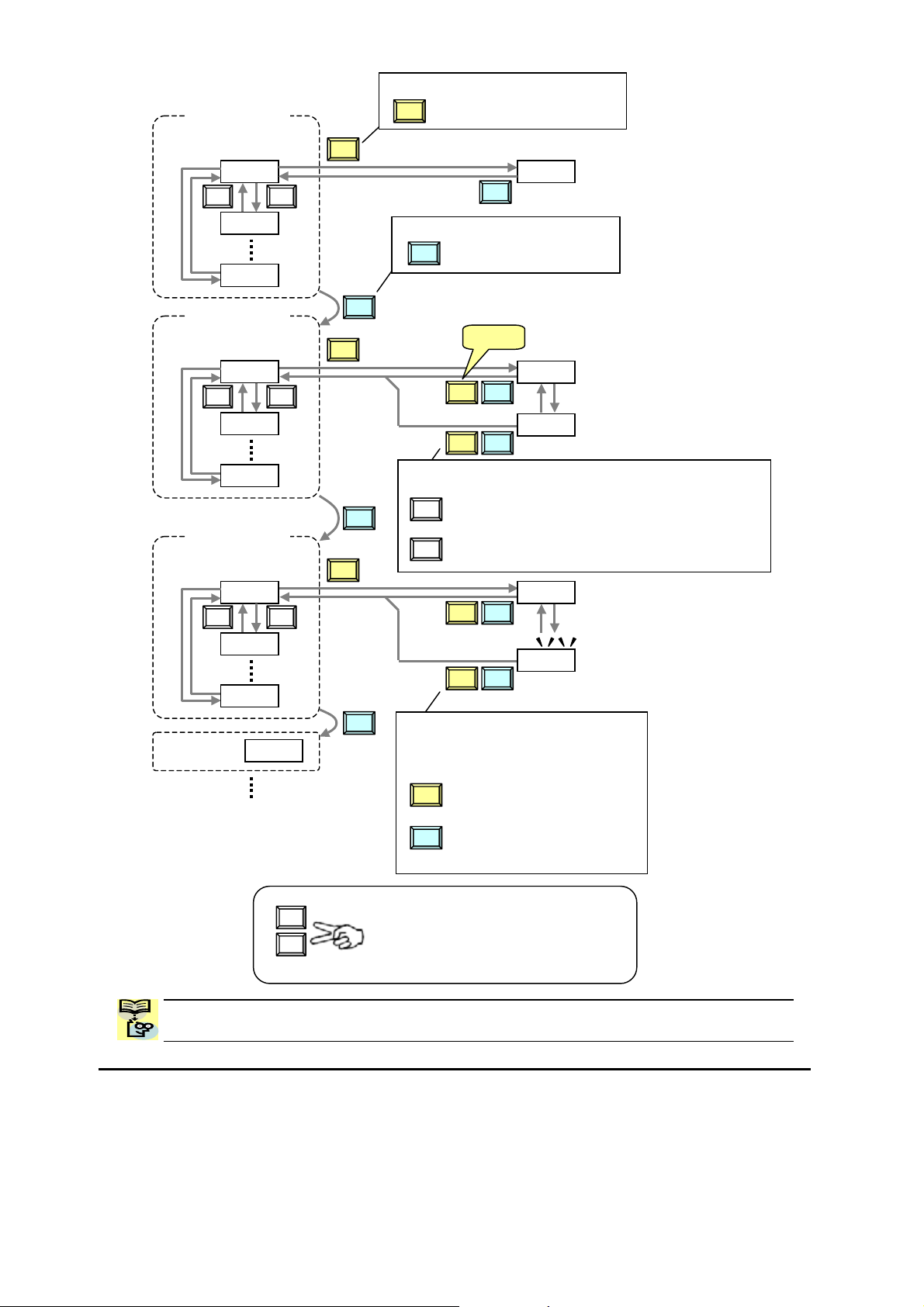
Group "d"
Func. code display
d001
V U
d002
d104
Group "F"
Func. code display
F001
V U
SET
SET
Func. code display
SET
Func. code display
ESC
: Moves to data display
ESC
: Jumps to the next group
ESC
Save
SET ESC
0.00
50.00
Func. code display
F002
F004
Group "A"
A001
V U
A002
SET
ESC
SET ESC
Data display (F001 to F003)
Data does not blink because of real time synchronizing
: Saves the data in EEPROM
SET
and returns to func. code display.
ESC
: Returns to func. code display without saving data.
SET ESC
Group "b"
A165
b001
ESC
Data display
When data is changed, the display
starts blinking, which means that
new data has not been activated yet.
SET ESC
: Saves the data in EEPROM and
SET
returns to func. code display.
: Cancels the data change and
ESC
returns to func. code display.
50.01
00
01
U
V
Press the both up and down key at the same
time in func. code or data display, then
single-digit edit mode will be enabled.
Refer to 2-34 for further information.
NOTE: Pressing the [ESC] key will make the display go to the top of next function group,
regardless the display contents. (e.g. A021 Æ [ESC] Æ b001)
16
Page 19
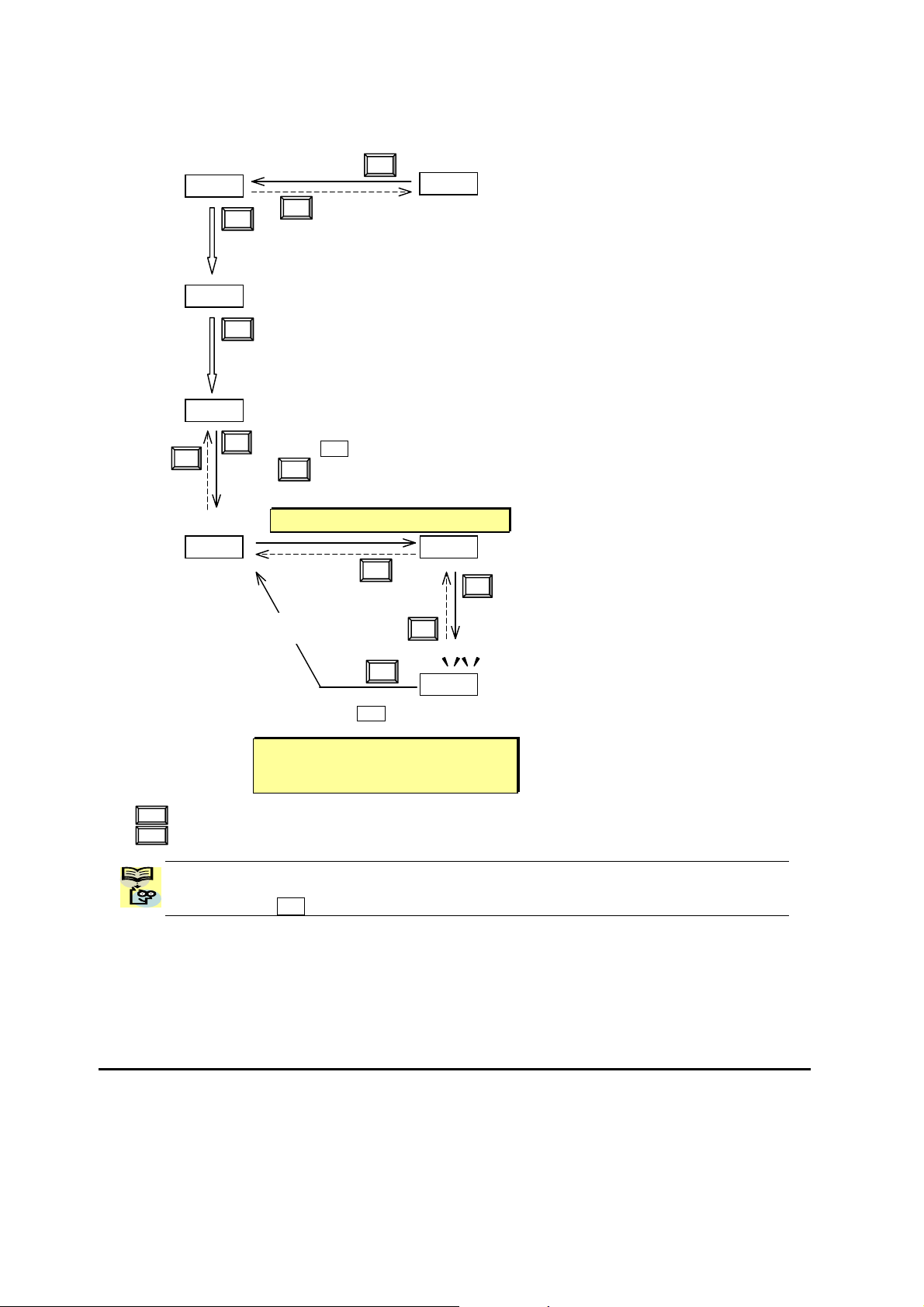
[Setting example]
After power ON, changing from 0.00 display to change the b083 (carrier frequency) data.
d Press [ESC] key to show
the function code
d001
ESC
ESC
SET
c Data of d001 will be shown on the
display after the first power ON
0.00
e Press [ESC] key to move
F001
on to the function group F001
ESC
V
f Press [ESC] key twice to move
on to the function group b001.
b001
g Press Up key to change increase
function code (b001
U
h Press SET key to display the data of b083
SET
Æ b083)
b083
i Press up key to increase the
data (5.0 Æ 12.0)
Display is solid lighting.
5.0
ESC
U
V
i Press SET key to set
and save the data
When data is changed, the display
starts blinking, which means that new
data has not been activated yet.
SET
12.0
:Cancels the change and moves back to the function code
ESC
:Fix and stores the data and moves back to the function code
SET
Function code dxxx are for monitor and not possible to change.
Function codes Fxxx other than F004 are reflected on the performance just after changing the data
(before pressing SET key), and there will be no blinking.
17
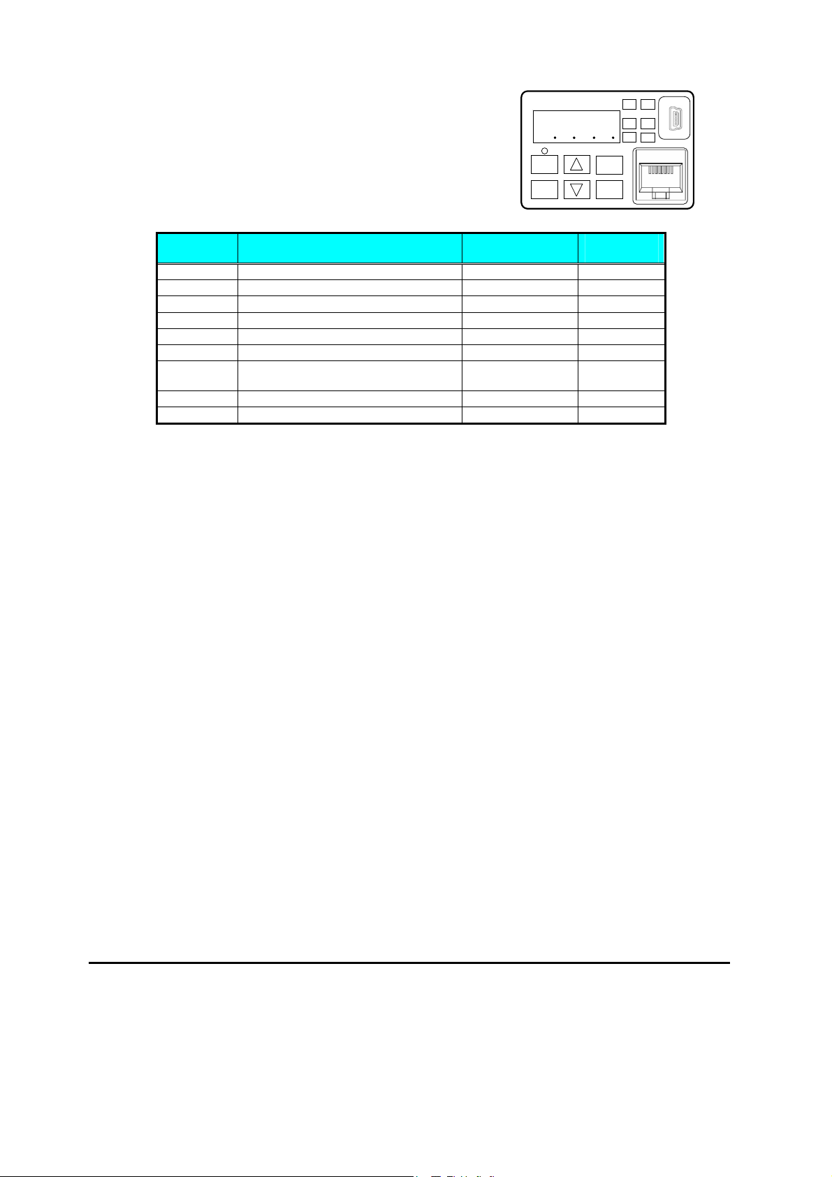
Page 20

ESC key
SET key
U key
V key
Note
Keep pressing for more than 1 second leads to d001 display, regardless the display situation. But note that
the display will circulates while keep pressing the [ESC] key because of the original function of the key.
(e.g. F001 Æ A001 Æ b001 Æ C001 Æ …Æ displays 50.00 after 1 second)
When a function
code is shown…
Move on to the next
function group
Move on to the data
display
Increase function
code
Decrease function
code
When a data is shown…
Cancels the change and
moves back to the function
code
Fix and stores the data and
moves back to the function
code
Increase data value
Decrease data value
18
Page 21
Connecting to PLCs and Other Devices
Hitachi inverters (drives) are useful in many types of applications. During installation, the
inverter keypad (or other programming device) will facilitate the initial configuration. After
installation, the inverter will generally receive its control commands through the control
logic connector or serial interface from another controlling device. In a simple application
such as single-conveyor speed control, a Run/Stop switch and potentiometer will give the
operator all the required control. In a sophisticated application, you may have a
programmable logic controller (PLC) as the system controller, with several connections to
the inverter.
It is not possible to cover all the possible types of application in this manual. It will be
necessary for you to know the electrical characteristics of the devices you want to connect
to the inverter. Then, this section and the following sections on I/O terminal functions can
help you quickly and safely connect those devices to the inverter.
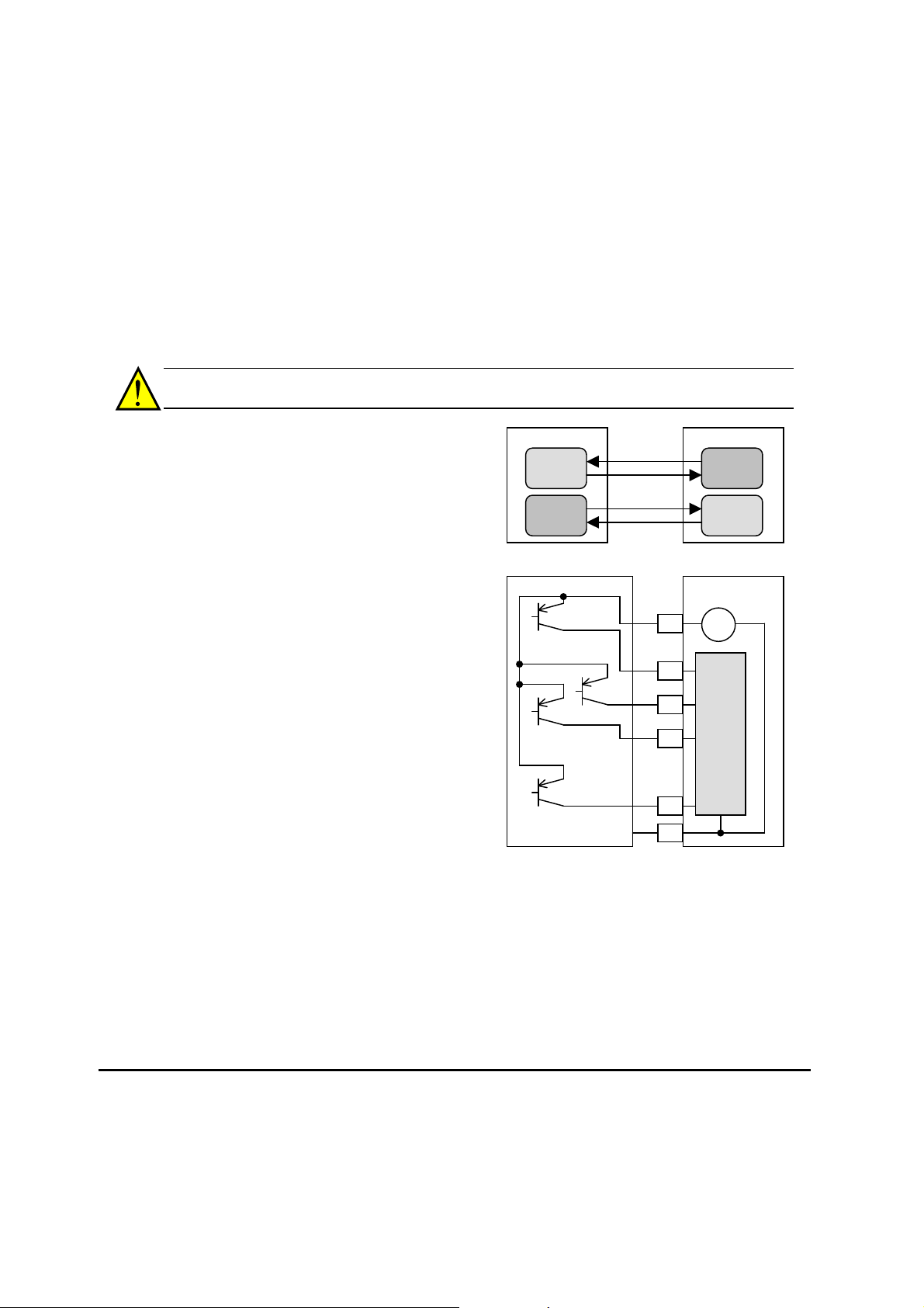
CAUTION: It is possible to damage the inverter or other devices if your application
exceeds the maximum current or voltage characteristics of a connection point.
The connections between the inverter and
other devices rely on the electrical input/output
characteristics at both ends of each connection,
shown in the diagram to the right. The
inverter’s configurable inputs accept either a
sourcing or sinking output from an external
Other device
Input
circuit
Output
circuit
signal
return
signal
return
WJ200 inverter
Output
circuit
Input
circuit
device (such as PLC). This chapter shows the
inverter’s internal electrical component(s) at
each I/O terminal. In some cases, you will
need to insert a power source in the interface
wiring.
Other device WJ200 inverter
24V
P24
+ -
In order to avoid equipment damage and get
your application running smoothly, we
recommend drawing a schematic of each
connection between the inverter and the other
device. Include the internal components of
each device in the schematic, so that it makes
a complete circuit loop.
…
1
2
3
…
Input
circuits
After making the schematic, then:
1. Verify that the current and voltage for each
connection is within the operating limits of
GND
7
L
each device.
2. Make sure that the logic sense (active high or active low) of any ON/OFF connection is
correct.
3. Check the zero and span (curve end points) for analog connections, and be sure the
scale factor from input to output is correct.
4. Understand what will happen at the system level if any particular device suddenly
loses power, or powers up after other devices.
19
Page 22
A
r
(L1)
(L2)
A
A
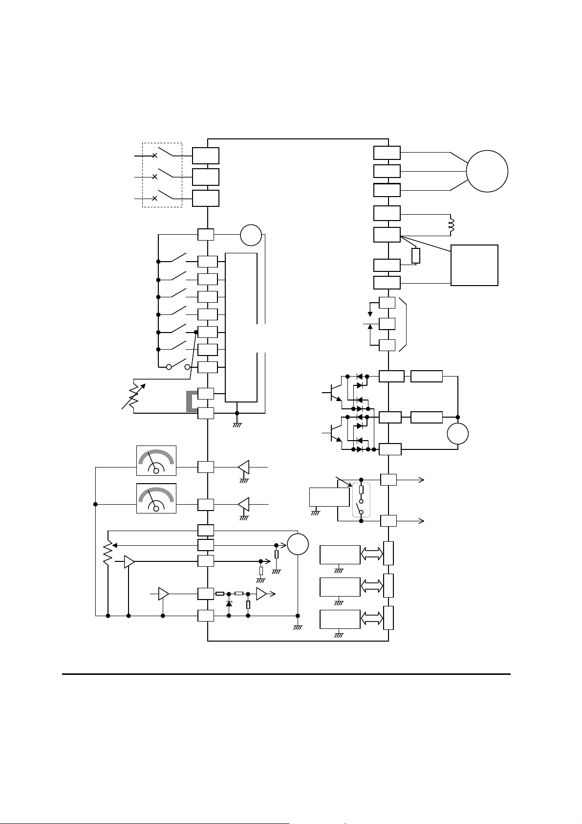
Example Wiring Diagram
The schematic diagram below provides a general example of logic connector wiring, in
addition to basic power and motor wiring converted in Chapter 2. The goal of this chapter
is to help you determine the proper connections for the various terminals shown below for
your application needs.
Breaker, MCCB
or GFI
Power source,
3-phase or
1-phase, per
inverter model
Intelligent inputs,
NOTE: For the wiring
of intelligent I/O and
analog inputs, be sure
to use twisted pair /
shielded cable. Attach
the shielded wire for
each signal to its
respective common
terminal at the inverter
end only.
Input impedance of
each intelligent input is
4.7k
7 terminals
Thermistor
Short bar
(Source type)
GND for logic inputs
Forward
R
S
T
N(L3)
P24
1
2
3/GS1
4/GS2
5/PTC
6
7/EB
PLC
L
Input
circuits
[5] configurable as
discrete input or
thermistor input
L
24V
+ -
WJ200
Output circuit
U(T1)
V(T2)
W(T3)
PD/+1
P/+
RB
N/-
AL1
AL0
AL2
11/EDM
Relay contacts,
type 1 Form C
Open collector output
12
DC reactor
(optional)
Brake
resistor
(optional)
Freq. arrival signal
Load
Load
Braking
unit (optional)
+
Moto
Meter
Meter
nalog reference
0~10VDC
4~20mA
Pulse train input
24Vdc 32kHz max.
GND for analog signals
EO
AM
H
O
OI
EA
L
L
L
pprx.10k
pprx.100
Termination resistor (200)
(Change by slide switch)
RS485
transceiver
L
10Vdc
+
L
L
RS485
transceiver
L
USB
transceiver
L
Option port
controller
L
CM2
GND for logic outputs
SP
Serial communication port
(RS485/ModBus)
SN
NOTE: Common for
RJ45 port
(Optional operator port)
USB (mini-B) port
(PC communication port)
USB power: Self power
Option port connector
RS485 is “L”.
20
Page 23
p
p
p
put
5 4 6 SN 7
OI L H O EA SP EO
A
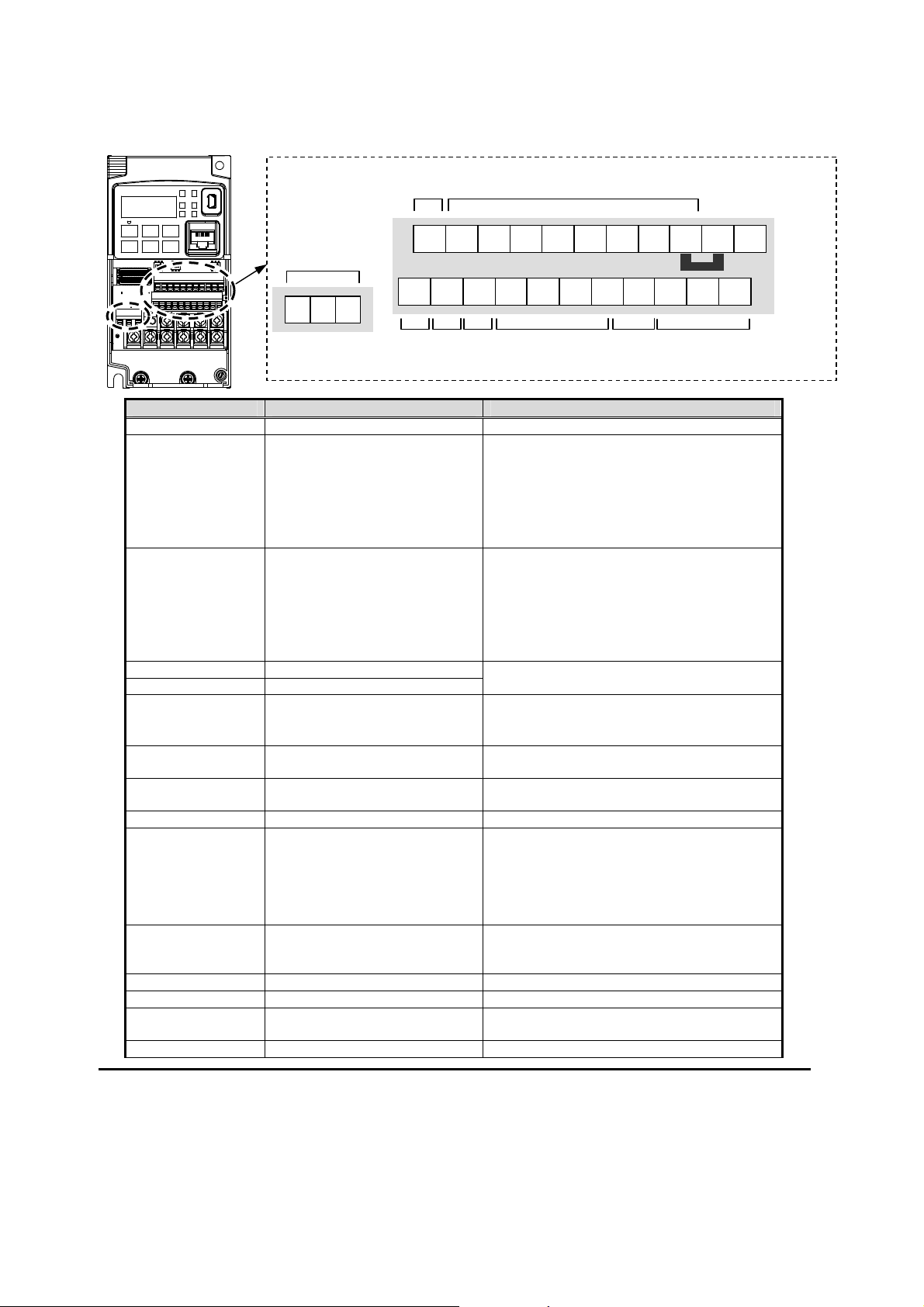
Control Logic Signal Specifications
The control logic connectors are located just behind the front housing cover. The relay
contacts are just to the left of the logic connectors. Connector labeling is shown below.
Relay
contacts
L2 AL1 AL0
RS485
comm.
Logic inputs
12 11 AM CM2
PLC
P24 1 L 3 2
Short bar
ut
Logic
out
ut
Pulse
RS485
comm.
Pulse
Train
out
Train
input
Analog
ut
in
Analog
out
Terminal Name Description Ratings
P24 +24V for logic inputs 24VDC, 100mA. (do not short to terminal L)
PLC Intelligent input common Factory set: Source type for –FE and –FU
models (connecting [P24] to [1]~[7] turns
each input ON). To change to sink type,
remove the short bar between [PLC] and [L],
and connect it between [P24] and [L]. In this
case, connecting [L] to [1]~[7] makes each
input ON.
1
2
3/GS1
4/GS2
5/PTC
6
7/EB
GS1(3) Safe stop input GS1
GS2(4) Safe stop input GS2
PTC(5) Motor thermistor input Connect motor thermistor between PTC and
EB(7) Pulse train input B 2kHz max.
EA Pulse train input A 32kHz max.
L (in upper row) *1 GND for logic inputs Sum of input [1]~[7] currents (return)
11/EDM Discrete logic outputs [11]
12 Discrete logic outputs [12] 50mA max. ON state current,
CM2 GND for logic output 100 mA: [11], [12] current return
AM Analog voltage output 0~10VDC 2mA maximum
EO Pulse train output 10VDC 2mA maximum
L (in bottom row) *2 GND for analog signals Sum of [OI], [O], and [H] currents (return)
Discrete logic inputs
(Terminal [3],[4],[5] and [7]
have dual function. See
following description and
related pages for the details.)
(Terminal [11] has dual
function. See following
description and related pages
for the details.)
27VDC max. (use PLC or an external supply
referenced to terminal L)
Functionality is based on ISO13849-1
See appendix for the details.
L terminal to detect the motor temperature.
Set 19 in C005.
Common is [PLC]
Common is [L]
50mA max. ON state current,
27 VDC max. OFF state voltage
Common is CM2
In case the EDM is selected, the functionality
is based on ISO13849-1
4VDC max. ON state voltage depression
27 VDC max. OFF state voltage
Common is CM2
32kHz maximum
21
Page 24
(
(
)
Terminal Name Description Ratings
OI Analog current input 4 to 19.6 mA range, 20 mA nominal,
input impedance 100
O Analog voltage input 0 to 9.8 VDC range, 10 VDC nominal,
input impedance 10 k
H +10V analog reference 10VDC nominal, 10mA max.
SP, SN Serial communication terminal For RS485 Modbus communication.
AL0, AL1, AL2 *3 Relay common contact 250VAC, 2.5A (R load) max.
250VAC, 0.2A (I load, P.F.=0.4) max.
100VAC, 10mA min.
30VDC, 3.0A (R load) max.
30VDC, 0.7A (I load, P.F.=0.4) max.
5VDC, 100mA min.
Note 1: The two terminals [L] are electrically connected together inside the inverter.
Note 2: We recommend using [L] logic GND (to the right) for logic input circuits and [L]
analog GND (to the left) for analog I/O circuits.
Note 3: Refer to page 39 for details of trip signals.
Wiring sample of control logic terminal (source logic)
SN 7/EB 6 5/PTC 4/GS2 3/GS1
SP EO EA H O OI L AM CM2 12 11/EDM
Variable resistor
for freq. setting
1k-2k)
Freq. meter
Note: If relay is connected to intelligent output, install a diode across the relay coil
(reverse-biased) in order to suppress the turn-off spike.
Short bar
source logic
1 L PLC P24
RY
RY
22
Page 25
1 2
Sink/source logic of intelligent input terminals
Sink or source logic is switched by a short bar as below.
Sink logic
L 1 2
PLC P24
Short bar
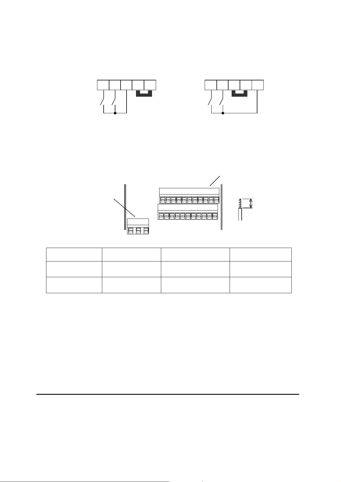
Wire size for control and relay terminals
Use wires within the specifications listed below. For safe wiring and reliabi li ty, it is
recommended to use ferrules, but if solid or stranded wire is used, stripping length should be
8mm.
Relay output terminal
Solid
Control logic
terminal
Relay terminal
2
mm
(AWG)
0.2 to 1.5
(AWG 24 to 16)
0.2 to 1.5
(AWG 24 to 16)
mm2 (AWG)
(AWG 24 to 17)
(AWG 24 to 17)
Source logic
Stranded
0.2 to 1.0
0.2 to 1.0
PLC P24 L
Short bar
Control logic terminal
8mm
Ferrule
mm2 (AWG)
0.25 to 0.75
(AWG 24 to 18)
0.25 to 0.75
(AWG 24 to 18)
23
Page 26
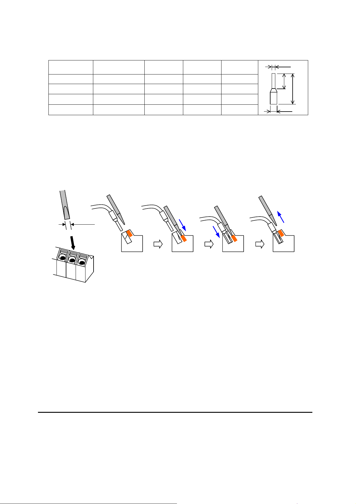
Recommendedferrule
For safe wiring and reliability, it is recommended to use following ferrules.
Wire size
2
mm
(AWG)
0.25 (24) AI 0.25-8YE 12.5 0.8 2.0
0.34 (22) AI 0.34-8TQ 12.5 0.8 2.0
0.5 (20) AI 0.5-8WH 14 1.1 2.5
0.75 (18) AI 0.75-8GY 14 1.3 2.8
* Supplier: Phoenix contact
Crimping pliers: CRIPMFOX UD 6-4 or CRIMPFOX ZA 3
Howtoconnect?
(1) Push down an orange actuating lever by a slotted screwdriver (width 2.5mm max.).
(2) Plug in the conductor.
(3) Pull out the screwdriver then the conductor is fixed.
Model name of
ferrule *
L [mm] Φd [mm] ΦD [mm]
Push down an
orange actuating
lever.
Plug in the
conductor.
Φd
8
L
ΦD
Pull out the
screwdriver to fix
the conductor.
24
Page 27

Intelligent Terminal Listing
Intelligent Inputs
Use the following table to locate pages for intelligent input material in this chapter.
Input Function Summary Table
Symbol Code Function Name Page
FW 00 Forward Run/Stop
RV 01 Reverse Run/Stop
CF1 02 Multi-speed Select, Bit 0 (LSB)
CF2 03 Multi-speed Select, Bit 1
CF3 04 Multi-speed Select, Bit 2
CF4 05 Multi-speed Select, Bit 3 (MSB)
JG 06 Jogging
DB 07 External DC braking
SET 08 Set (select) 2nd Motor Data
2CH 09 2-stage Acceleration and Deceleration
FRS 11 Free-run Stop
EXT 12 External Trip
USP 13 Unattended Start Protection
CS 14 Commercial power source switchover
SFT 15 Software Lock
AT 16 Analog Input Voltage/Current Select
RS 18 Reset Inverter
PTC 19 PTC thermistor Thermal Protection
STA 20 Start (3-wire interface)
STP 21 Stop (3-wire interface)
F/R 22 FWD, REV (3-wire interface)
PID 23 PID Disable
PIDC 24 PID Reset
UP 27 Remote Control UP Function
DWN 28 Remote Control Down Function
UDC 29 Remote Control Data Clearing
OPE 31 Operator Control
SF1~SF7 32~38 Multi-speed Select,Bit operation Bit 1~7
OLR 39 Overload Restriction Source Changeover
TL 40 Torque Limit Selection
TRQ1 41 Torque limit switch 1
TRQ2 42 Torque limit switch 2
BOK 44 Brake confirmation
LAC 46 LAD cancellation
PCLR 47 Pulse counter clear
ADD 50 ADD frequency enable
F-TM 51 Force Terminal Mode
ATR 52 Permission for torque command input
KHC 53 Clear watt-hour data
MI1~MI7 56~62 General purpose input (1)~(7)
AHD 65 Analog command hold
CP1~CP3 66~68 Multistage-position switch (1)~(3)
ORL 69 Limit signal of zero-return
ORG 70 Trigger signal of zero-return
SPD 73 Speed/position changeover
GS1 77 STO1 input (Safety related signal)
GS2 78 STO2 input (Safety related signal)
485 81 Starting communication signal
PRG 82 Executing EzSQ program
HLD 83 Retain output frequency
ROK 84 Permission of Run command
EB 85 Rotation direction detection (phase B)
25
Page 28

Use the following table to locate pages for intelligent input material in this chapter.
Symbol Code Function Name Page
DISP 86 Display limitation
NO 255 No assign
Intelligent Outputs
Use the following table to locate pages for intelligent output material in this chapter.
Symbol Code Function Name Page
RUN 00 Run Signal
FA1 01 Frequency Arrival Type 1–Constant Speed
FA2 02 Frequency Arrival Type 2–Over frequency
OL 03 Overload Advance Notice Signal
OD 04 PID Deviation error signal
AL 05 Alarm Signal
FA3 06 Frequency Arrival Type 3–Set frequency
OTQ 07 Over/under Torque Threshold
UV 09 Undervoltage
TRQ 10 Torque Limited Signal
RNT 11 Run Time Expired
ONT 12 Power ON time Expired
THM 13 Thermal Warning
BRK 19 Brake Release Signal
BER 20 Brake Error Signal
ZS 21 Zero Hz Speed Detection Signal
DSE 22 Speed Deviation Excessive
POK 23 Positioning Completion
FA4 24 Frequency Arrival Type 4–Over frequency
FA5 25 Frequency Arrival Type 5–Set frequency
OL2 26 Overload Advance Notice Signal 2
ODc 27 Analog Voltage Input Disconnect Detection
OIDc 28 Analog Voltage Output Disconnect Detection
FBV 31 PID Second Stage Output
NDc 32 Network Disconnect Detection
LOG1~3 33~35 Logic Output Function 1~3
WAC 39 Capacitor Life Warning Signal
WAF 40 Cooling Fan Warning Signal
FR 41 Starting Contact Signal
OHF 42 Heat Sink Overheat Warning
LOC 43 Low load detection
MO1~3 44~46 General Output 1~3
IRDY 50 Inverter Ready Signal
FWR 51 Forward Operation
RVR 52 Reverse Operation
MJA 53 Major Failure Signal
WCO 54 Window Comparator for Analog Voltage Input
WCOI 55 Window Comparator for Analog Current Input
FREF 58 Frequency Command Source
REF 59 Run Command Source
SETM 60 2nd Motor in operation
EDM 62 STO (Safe Torque Off) Performance Monitor
OP 63 Option control signal
no 255 Not used
Input Function Summary Table
Input Function Summary Table
(Output terminal 11 only)
26
Page 29
Using Intelligent Input Terminals
Terminals [1], [2], [3], [4], [5], [6] and [7] are identical, programmable inputs for general use.
The input circuits can use the inverter’s internal (isolated) +24V field supply or an external
power supply. This section describes input circuits operation and how to connect them
properly to switches or transistor outputs on field devices.
The WJ200 inverter features selectable sinking or sourcing inputs. These terms refer to the
connection to the external switching device–it either sinks current (from the input to GND)
or sources current (from a power source) into the input. Note that the sink/source naming
convention may be different in your particular country or industry. In any case, just follow
the wiring diagrams in this section for your application.
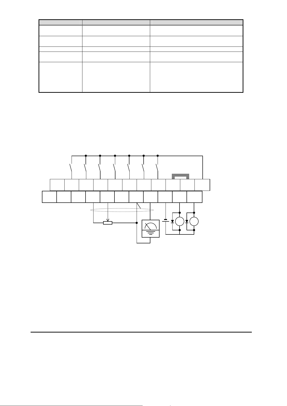
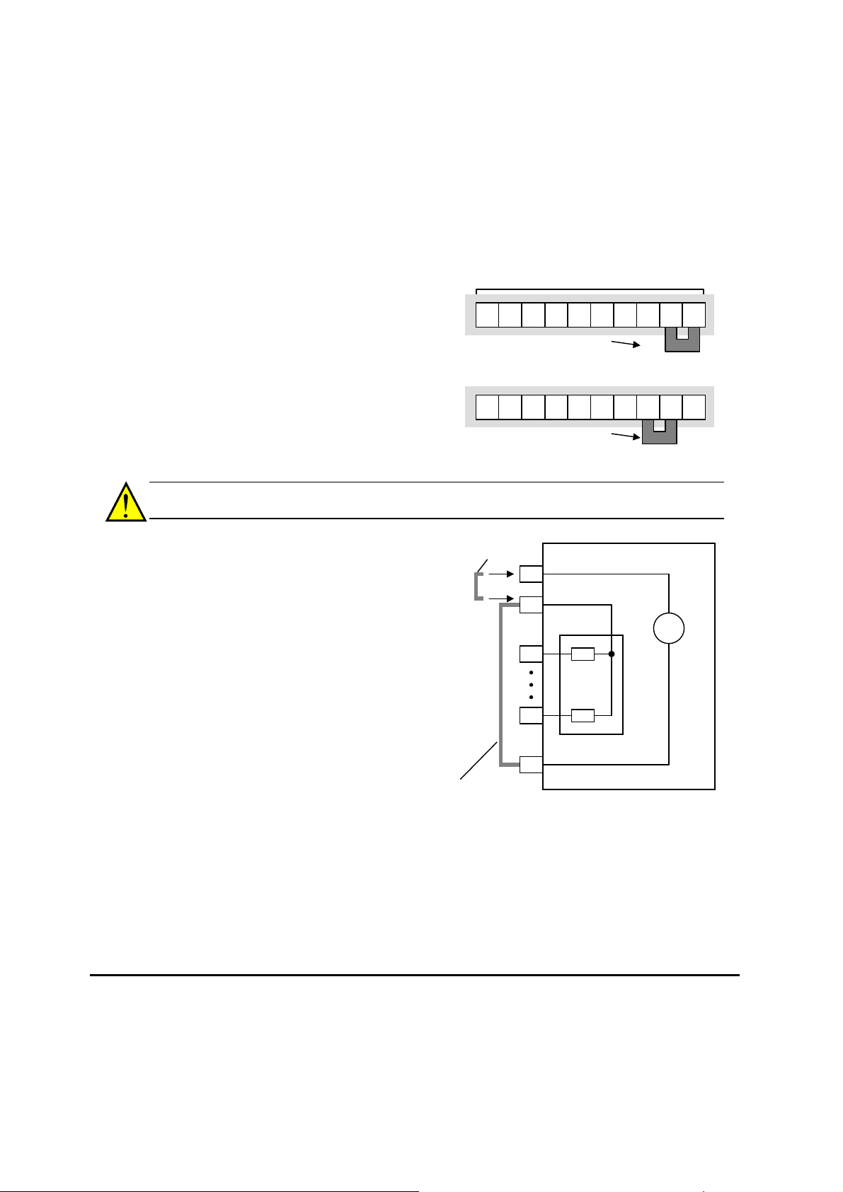
The inverter has a short bar (jumper) for
Logic inputs
configuring the choice of sinking or sourcing
inputs. To access it, you must remove the
7 6
5 4 3 2 1 L
PLC P24
front cover of the inverter housing. In the
figure to the top right, the short bar is shown
as attached to the logic terminal block
(connector). For EU and US version (suffix
Short bar
Sink logic connection
–xFE, and –xFU), it is originally located as
source type logic. If you need to change to
the sink type connection, remove the short
bar and connect it as shown in the figure at
the bottom right.
7 6
5 4 3 2 1 L
Short bar
Source logic connection
PLC P24
CAUTION: Be sure to turn OFF power to the inverter before changing the short circuit bar
position. Otherwise, damage to the inverter circuitry may occur.
[PLC] Terminal Wiring – The [PLC]
terminal (Programmable Logic Control
terminal) is named to include various
devices that can connect to the inverter’s
logic inputs. In the figure to the right, note
the [PLC] terminal and the short bar
(jumper). Locating the short bar between
[PLC] and [L] sets the input logic source
type, which is the default setting for EU
and US versions. In this case, you
Short bar for
sink logic
P24
PLC
Input common
1
Input
circuits
WJ200 inverter
24V
+
-
connect input terminal to [P24] to make it
active. If instead you locate the short bar
7
between [PLC] and [P24], the input logic
will be sink type. In this case, you
connect the input terminal to [L] to make
it active.
Short bar for
source logic
Logic GND
L
The wiring diagram on the following pages show the four combinations of using sourcing or
sinking inputs, and using the internal or an external DC supply.
27
Page 30

The two diagrams below input wiring circuits using the inverter’s internal +24V supply.
Each diagram shows the connection for simple switches, or for a field device with
transistor outputs. Note that in the lower diagram, it is necessary to connect terminal [L]
only when using the field device with transistors. Be sure to use the correct connection of
the short bar shown for each wiring diagram.
Sinking Inputs, Internal Supply
Short bar = [PLC] – [P24] position
Field device
GND
Short bar
Logic GND
P24
Input common
PLC
L
WJ200
24V
+
1
7
Open collector outputs,
NPN transistors
Sourcing Inputs, Internal Supply
Short bar = [PLC] – [L] position
Field device
Common to
[P24]
1
7
to PNP bias
circuits
GND
Input switches
Short bar
Logic GND
Input switches
1
7
P24
Input common
PLC
L
1
7
Input
circuits
WJ200
24V
+
Input
circuits
PNP transistor
sousing outputs
28
Page 31

f
The two diagrams below show input wiring circuits using an external supply. If using the
“Sinking Inputs, External Supply” in below wiring diagram, be sure to remove the short bar,
and use a diode (*) with the external supply. This will prevent a power supply contention in
case the short bar is accidentally placed in the incorrect position. For the “Sourcing Inputs,
External Supply”, please connect the short bar as drawn in the diagram below.
Sinking Inputs, External Supply
Short bar = Removed
Field device
+
24V
GND
24V
+
Logic GND
WJ200
P24
*
Input common
PLC
L
24V
+
1
7
Open collector outputs,
NPN transistors
Sourcing Inputs, External Supply
Short bar = [PLC] – [L]
PNP transistor
sourcing outputs
Field device
1
7
+
24V
GND
1
Input
circuits
7
Input switches
* Note: Make sure to remove the short circuit bar in case o
using an external power supply.
Short bar
WJ200
24V
+
Input switches
P24
Input common
PLC
L
1
7
Input
circuits
24V
+
29
Page 32

CAUTION: Be sure to diode in between "P24" and "PLC" when connecting plural
inverters with digital input wiring in common.
The power to the inverter control part can be supplied externally as shown below. Except
driving motor, it is possible read and write the parameters by keypad and via
communication even the drive itself is not powered.
By having ability inverter doesn’t block the current flowing into itself when it is not
powered. This may cause the closed circuit when two or more inverters are connected to
common I/O wiring as shown below to result in unexpected turning the on the input. To
avoid this closed circuit, please put the diode (rated:50V/0.1A) in the path as described
below.
Switch
OFF
Short
bar
Short
OFF
Short
bar
Short
bar
bar
Power ON
PLC
L
1
Power OFF
PLC
L
1
P24
PLC
L
1
P24
PLC
L
1
Input
ON
Inserting
diode
In case of Source logic
Input
ON
Switch
OFF
Switch
OFF
P24
PLC
L
P24
PLC
L
1
P24
PLC
L
1
P24
PLC
L
1
Power ON
Input
OFF
Power OFF
Input
OFF
Switch
30
Page 33

Forward Run/Stop and Reverse Run/Stop Commands:
When you input the Run command via the terminal [FW], the inverter executes the Forward
Run command (high) or Stop command (low). When you input the Run command via the
terminal [RV], the inverter executes the Reverse Run command (high) or Stop command
(low).
Option
Code
00
01
Valid for inputs:
Required settings
Notes:
When the Forward Run and Reverse Run
When a terminal associated with either [FW] or
Terminal
Symbol
FW Forward Run/Stop
RV Reverse Run/Stop
commands are active at the same time, the
inverter enters the Stop Mode.
[RV] function is configured for normally closed,
the motor starts rotation when that terminal is
disconnected or otherwise has no input voltage.
Function Name State Description
ON Inverter is in Run Mode, motor runs forward
OFF Inverter is in Stop Mode, motor stops
ON Inverter is in Run Mode, motor runs reverse
OFF Inverter is in Stop Mode, motor stops
C001~C007
A002 = 01
Example (default input configuration shown
– see page 3-49)
7654321L
See I/O specs on page 4-6.
RV FW
PLC
PCS
P24
NOTE: The parameter F004, Keypad Run Key Routing, determines whether the single Run
key issues a Run FWD command or Run REV command. However, it has no effect on the
[FW] and [RV] input terminal operation.
WARNING: If the power is turned ON and the Run command is already active, the motor
starts rotation and is dangerous! Before turning power ON, confirm that the Run command
is not active.
31
Page 34

Multi-Speed Select ~Binary Operation
The inverter can store up to 16 different target
frequencies (speeds) that the motor output uses for
steady-state run condition. These speeds are accessible
through programming four of the intelligent terminals as
binary-encoded inputs CF1 to CF4 per the table to the
right. These can be any of the six inputs, and in any
order. You can use fewer inputs if you need eight or
fewer speeds.
NOTE: When choosing a subset of speeds to use,
always start at the top of the table, and with the
least-significant bit: CF1, CF2, etc.
[CF1]
[CF2]
[CF3]
[FW]
3rd
7th
5th
2nd
1st
6th
4th
0th
1
0
1
0
1
0
1
0
Speed
Option
Code
02
03
04
05
Valid for inputs:
Required settings
Notes:
When programming the multi-speed settings,
be sure to press the SET key each time and then
set the next multi-speed setting. Note that when
the key is not pressed, no data will be set.
When a multi-speed setting more than 50Hz
(60Hz) is to be set, it is necessary to program the
maximum frequency A004 high enough to allow
that speed
Terminal
Symbol
Function Name State Description
CF1 Multi-speed Select,
Bit 0 (LSB)
CF2 Multi-speed Select,
Bit 1
CF3 Multi-speed Select,
Bit 2
CF4 Multi-speed Select,
Bit 3 (MSB)
C001~C007
F001, A001=02,
A020 to A035
Multi-
speed
CF4 CF3 CF2 CF1
Speed 0 0 0 0 0
Speed 1 0 0 0 1
Speed 2 0 0 1 0
Speed 3 0 0 1 1
Speed 4 0 1 0 0
Speed 5 0 1 0 1
Speed 6 0 1 1 0
Speed 7 0 1 1 1
Speed 8 1 0 0 0
Speed 9 1 0 0 1
Speed 10 1 0 1 0
Speed 11 1 0 1 1
Speed 12 1 1 0 0
Speed 13 1 1 0 1
Speed 14 1 1 1 0
Speed 15 1 1 1 1
Input Function
The example with eight speeds in the
figure below shows how input switches
configured for CF1–CF3 functions can
change the motor speed in real time.
NOTE: Speed 0 depends on A001
parameter value.
ON Binary encoded speed select, Bit 0, logical 1
OFF Binary encoded speed select, Bit 0, logical 0
ON Binary encoded speed select, Bit 1, logical 1
OFF Binary encoded speed select, Bit 1, logical 0
ON Binary encoded speed select, Bit 2, logical 1
OFF Binary encoded speed select, Bit 2, logical 0
ON Binary encoded speed select, Bit 3, logical 1
OFF Binary encoded speed select, Bit 3, logical 0
Example (some CF inputs require input
configuration; some are default inputs):
7654321L
See I/O specs on page 4–6.
CF4 CF3 CF2 CF1
PCS
PLC
P24
32
Page 35
q
Two Stage Acceleration and Deceleration
When terminal [2CH] is turned ON, the inverter
changes the rate of acceleration and
deceleration from the initial settings (F002 and
F003) to use the second set of acceleration/
deceleration values. When the terminal is
turned OFF, the inverter is returned to the
original acceleration and deceleration time
(F002 acceleration time 1, and F003
deceleration time 1). Use A092 (acceleration
time 2) and A093 (deceleration time 2) to set
the second stage acceleration and deceleration
times.
In the graph shown above, the [2CH] becomes active during the initial acceleration. This
causes the inverter to switch from using acceleration 1 (F002) to acceleration 2 (A092).
Option
Code
09
Valid for inputs:
Required settings
Notes:
Function A094 selects the method for second
stage acceleration. It must be set = 00 to select
the input terminal method in order for the [2CH]
terminal assignment to operate.
Terminal
Symbol
2CH Two-stage Accelera-
Function Name State Description
tion and
Deceleration
C001~C007
A092, A093, A094=00
ON Frequency output uses 2nd-stage acceleration and
deceleration values
OFF Frequency output uses the initial acceleration 1 and
deceleration 1 values
Example (default input configuration shown—see
page 3–49):
See I/O specs on page 4–6.
Target
fre
Output
frequency
[2CH]
[FW,RV]
2CH
7654321L
second
initial
1
0
1
0
uency
PCS
PLC
P24
t
33
Page 36

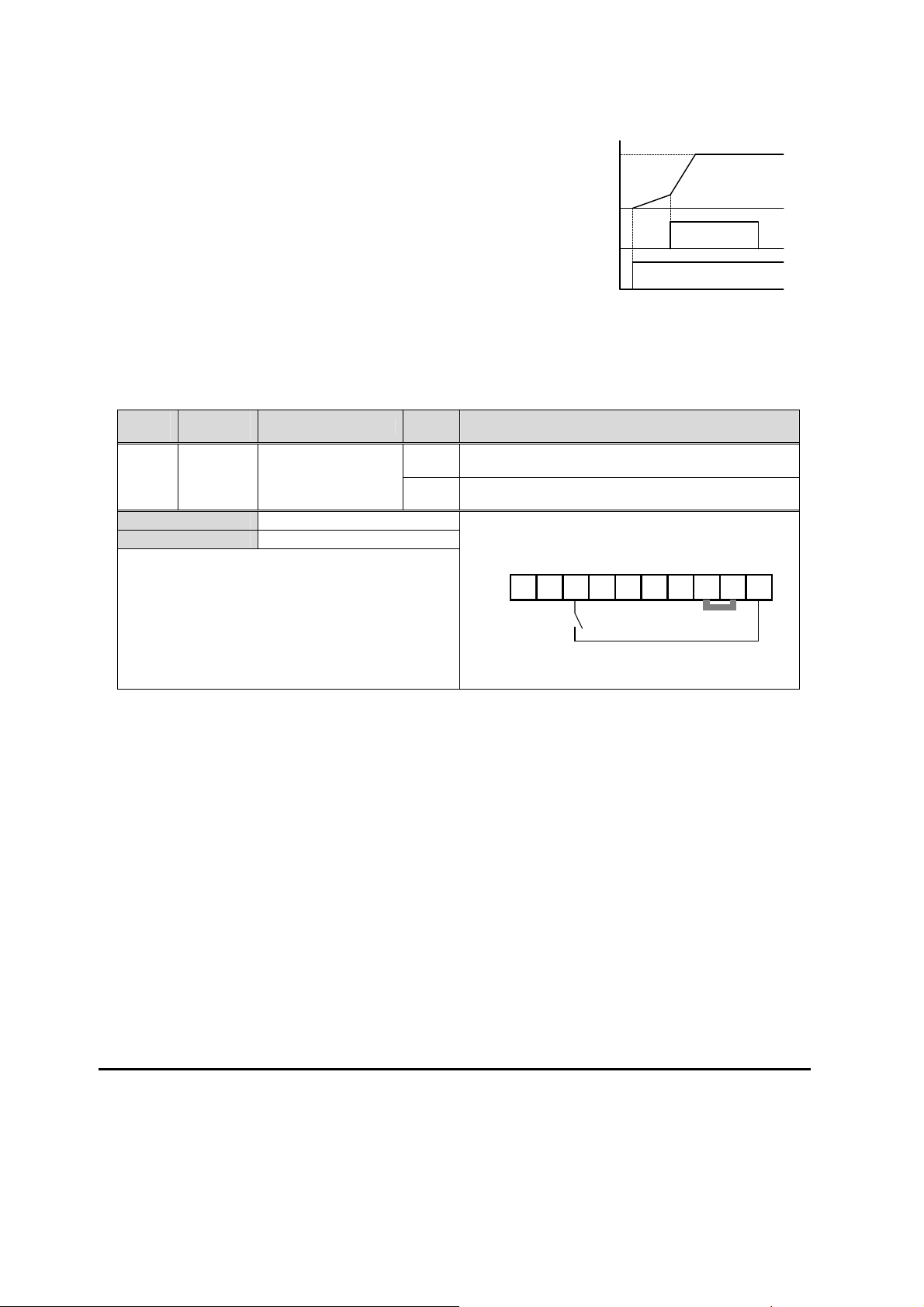
Unattended Start Protection
If the Run command is already set when power is turned ON, the inverter starts running
immediately after powerup. The Unattended Start Protection (USP) function prevents that
automatic startup, so that the inverter will not run without outside intervention. When USP
is active and you need to reset an alarm and resume running, either turn the Run
command OFF, or perform a reset operation by the terminal [RS] input or the keypad
Stop/reset key.
In the figure below, the [USP] feature is enabled. When the inverter power turns ON, the
motor does not start, even though the Run command is already active. Instead, it enters
the USP trip state, and displays E 13 error code. This requires outside intervention to reset
the alarm by turning OFF the Run command per this example (or applying a reset). Then
the Run command can turn ON again and start the inverter output.
Run command [FW,RV]
[USP] terminal
Alarm output terminal
Inverter output frequency
Inverter power supply
Events:
1
0
1
0
1
0
0
1
0
E13
Alarm
cleared
Run
command
t
Option
Code
13
Valid for inputs:
Required settings
Notes:
Note that when a USP error occurs and it is
canceled by a reset from a [RS] terminal input, the
inverter restarts running immediately.
Even when the trip state is canceled by turning
the terminal [RS] ON and OFF after an under
voltage protection E09 occurs, the USP function
will be performed.
When the running command is active
immediately after the power is turned ON, a USP
error will occur. When this function is used, wait
for at least three (3) seconds after the powerup to
generate a Run command.
Terminal
Symbol
USP Unattended Start
Function Name State Description
Protection
C001~C007
(none)
ON On powerup, the inverter will not resume a Run
OFF On powerup, the inverter will resume a Run
command (mostly used in the US)
command that was active before power loss
Example (default input configuration shown for
–FE and –FU models; –F models require input
configuration—see page 3–49):
See I/O specs on page 4–6.
7654321L
USP
PCS
PLC
P24
34
Page 37

Reset Inverter
The [RS] terminal causes the inverter to execute
the reset operation. If the inverter is in Trip Mode,
the reset cancels the Trip state. When the signal
[RS] is turned ON and OFF, the inverter executes
the reset operation. The minimum pulse width for
[RS] must be 12 ms or greater. The alarm output
will be cleared within 30 ms after the onset of the
Alarm
signal
[RS]
1
0
Approx. 30 ms
1
0
Reset command.
WARNING: After the Reset command is given and the alarm reset occurs, the motor will
restart suddenly if the Run command is already active. Be sure to set the alarm reset after
verifying that the Run command is OFF to prevent injury to personnel.
Option
Code
18
Valid for inputs:
Required settings
Notes:
While the control terminal [RS] input is ON, the
keypad displays alternating segments. After RS
turns OFF, the display recovers automatically.
Pressing the Stop/Reset key of the digital
operator can generate a reset operation only
when an alarm occurs.
Terminal
Symbol
RS Reset Inverter
Function Name State Description
C001~C007
(none)
ON The motor output is turned OFF, the Trip Mode is
cleared (if it exists), and powerup reset is applied
OFF Normal power ON operation
Example (default input configuration shown):
7654321L
See I/O specs on page 4–6.
RS
12 ms
minimum
PCS
P24
PLC
t
A terminal configured with the [RS] function can only be configured for normally open operation. The
terminal cannot be used in the normally closed contact state.
When input power is turned ON, the inverter performs the same reset operation as it does when a
pulse on the [RS] terminal occurs.
The Stop/Reset key on the inverter is only operational for a few seconds after inverter powerup when
a hand-held remote operator is connected to the inverter.
If the [RS] terminal is turned ON while the motor is running, the motor will be free running (coasting).
If you are using the output terminal OFF delay feature (any of C145, C147, C149 > 0.0 sec.), the [RS]
terminal affects the ON-to-OFF transition slightly. Normally (without using OFF delays), the [RS] input
causes the motor output and the logic outputs to turn OFF together, immediately. However, when any
output uses an OFF delay, then after the [RS] input turns ON, that output will remain ON for an additional
1 sec. period (approximate) before turning OFF.
35
Page 38

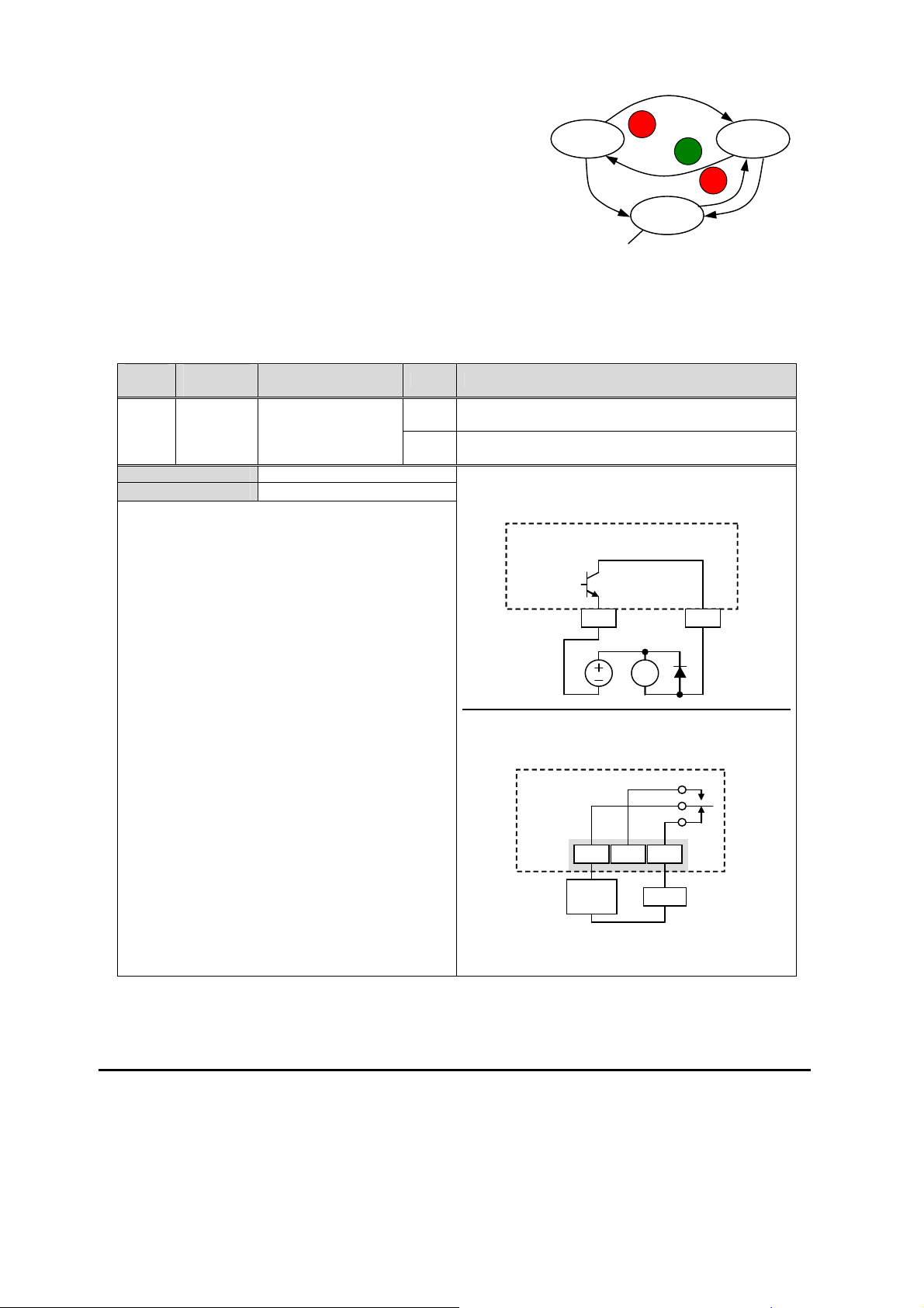
Run Signal
When the [RUN] signal is selected as an
intelligent output terminal, the inverter outputs
a signal on that terminal when it is in Run
Mode. The output logic is active low, and is
the open collector type (switch to ground).
Option
Code
00
Valid for inputs:
Required settings
Notes:
The inverter outputs the [RUN] signal
whenever the inverter output exceeds the start
frequency specified by parameter B082. The start
frequency is the initial inverter output frequency
when it turns ON.
The example circuit for terminal [11] drives a
relay coil. Note the use of a diode to prevent the
negative going turn-off spike generated by the coil
from damaging the inverter’s output transistor.
Terminal
Symbol
RUN Run Signal
Function Name State Description
11, 12, AL0 – AL2
(none)
[FW,RV]
Output
frequency
Run
signal
ON when inverter is in Run Mode
OFF when inverter is in Stop Mode
Example for terminal [11] (default output
configuration shown – see page 3-54):
1
0
B082
Inverter output
terminal circuit
CM2 11
start freq.
RY
ON
t
RUN
Example for terminal [AL0], [AL1], [AL2] (requires
output configuration – see page 4-35 and 3-54):
Inverter logic
circuit board
See I/O specs on page 4-6
AL0 AL2
Power
supply
RUN
AL1
Load
36
Page 39

Frequency Arrival Signals
The Frequency Arrival group of outputs helps coordinate external systems with the current
velocity profile of the inverter. As the name implies, output [FA1] turns ON when the output
frequency arrives at the standard set frequency (parameter F001). Output [FA2] relies on
programmable accel/ decel thresholds for increased flexibility. For example, you can have
an output turn ON at one frequency during acceleration, and have it turn OFF at a different
frequency during deceleration. All transitions have hysteresis to avoid output chatter if the
output frequency is near one of the thresholds.
Option
Code
Valid for inputs:
Required
settings
Notes:
For most applications you will need to use
For each frequency arrival threshold, the
The output turns OFF as the output
The example circuit for terminal [11] drives a
Terminal
Symbol
01
02
06
24
25
only one type of frequency arrival outputs (see
examples). However, it is possible assign both
output terminals to output functions [FA1] and
[FA2]
output anticipates the threshold (turns ON early)
by 1.5Hz
frequency moves away from the threshold,
delayed by 0.5Hz
relay coil. Note the use of a diode to prevent the
negative going turn-off spike generated by the
coil from damaging the inverter’s output
transistor
FA1 Frequency Arrival
FA2 Frequency Arrival
FA3 Frequency Arrival
FA4 Frequency Arrival
FA5 Frequency Arrival
Function Name State Description
ON when output to motor is at the constant frequency
Type 1 – Constant
Speed
Type 2 – Over
frequency
Type 3 – Set
frequency
Type 4 – Over
frequency (2)
Type 5 – Set
frequency (2)
11, 12, AL0 – AL2
C042, C043, C045, C046,
OFF when output to motor is OFF, or in any acceleration or
ON when output to motor is at or above the set frequency
OFF when output to motor is OFF, or during accel or decel
ON when output to motor is at the set frequency
OFF when output to motor is OFF, or in any acceleration or
ON when output to motor is at or above the set frequency
OFF when output to motor is OFF, or during accel or decel
ON when output to motor is at the set frequency
OFF when output to motor is OFF, or in any acceleration or
deceleration ramp
thresholds for, even if in acceleration or decel ramps
before the respective thresholds are crossed
deceleration ramp
thresholds for, even if in acceleration or decel ramps
before the respective thresholds are crossed
deceleration ramp
Example for terminal [11] (default output configuration
shown – see page 3-54):
Example for terminal [AL0], [AL1], [AL2] (requires
output configuration – see page 54):
See I/O specs on page 4-6
Inverter output
terminal circuit
CM2 11
Inverter logic
circuit board
AL0 AL2
Power
supply
FA1
RY
FA1
AL1
Load
37
Page 40

Frequency arrival output [FA1] uses the
standard output frequency (parameter
F001) as the threshold for switching. In
the figure to the right, Frequency Arrival
[FA1] turns ON when the output
frequency gets within Fon Hz below or
Fon Hz above the target constant
frequency, where Fon is 1% of the set
maximum frequency and Foff is 2% of
the set maximum frequency. This
provides hysteresis that prevents output
chatter near the threshold value. The
hysteresis effect causes the output to
turn ON slightly early as the speed
approaches the threshold. Then the
turn-OFF point is slightly delayed. Note
the active low nature of the signal, due to
the open collector output.
Frequency arrival output [FA2/FA4]
works the same way; it just uses two
separate thresholds as shown in the
figure to the right. These provide for
separate acceleration and deceleration
thresholds to provide more flexibility than
for [FA1]. [FA2/FA4] uses C042/C045
during acceleration for the ON threshold,
and C043/C046 during deceleration for the
OFF threshold. This signal also is active
low. Having different accel and decel
thresholds provides an asymmetrical
output function. However, you can use
equal ON and OFF thresholds, if desired.
Frequency arrival output [FA3/FA5] works
also the same way, only difference is
arriving at set frequency.
Output
freq.
0
FA1
signal
Output
freq.
thresholds
C042/C045
C043/C046
FA2/FA4
signal
Output
freq.
thresholds
C042/C045
C043/C046
Fon
Fon=1% of max. frequency
Foff=2% of max. frequency
0
Fon=1% of max. frequency
Foff=2% of max. frequency
F001
Fon
ON
Foff
Fon
Fon
ON
Foff
Fon
F001
Foff
ON
Foff
Foff
0
FA3/FA5
signal
Fon=1% of max. frequency
Foff=2% of max. frequency
ON ON
38
Page 41
A
A
A
Alarm Signal
The inverter alarm signal is active when a fault has
occurred and it is in the Trip Mode (refer to the
diagram at right). When the fault is cleared the alarm
Run Stop
STOP
RESET
RUN
signal becomes inactive.
We must make a distinction between the alarm signal
AL and the alarm relay contacts [AL0], [AL1] and [AL2].
Fault
Trip
The signal AL is a logic function, which you can assign
to the open collector output terminals [11], [12], or the
larm signal active
relay outputs.
The most common (and default) use of the relay is for AL, thus the labeling of its terminals.
Use an open collector output (terminal [11] or [12]) for a low-current logic signal interface
or to energize a small relay (50 mA maximum). Use the relay output to interface to higher
voltage and current devices (10 mA minimum).
Option
Code
05
Valid for inputs:
Required settings
Notes:
By default, the relay is configured as normally
closed (C036=01). Refer to the next page for an
explanation.
In the default relay configuration, an inverter
power loss turns ON the alarm output. the alarm
signal remains ON as long as the external control
circuit has power.
When the relay output is set to normally
closed, a time delay of less than 2 seconds occurs
after powerup before the contact is closed.
Terminals [11] and [12] are open collector
outputs, so the electric specifications of [AL] are
different from the contact output terminals [AL0],
[AL1], [AL2].
This signal output has the delay time (300 ms
nominal) from the fault alarm output.
The relay contact specifications are in “Control
Logic Signal Specifications” on page 4–6. The
contact diagrams for different conditions are on
the next page.
Terminal
Symbol
Function Name State Description
AL Alarm Signal
11, 12, AL0 – AL2
C031, C032, C036
ON when an alarm signal has occurred and has not
been cleared
OFF when no alarm has occurred since the last clearing
of alarm(s)
Example for terminal [11] (default output
configuration shown – see page 3-54):
Inverter output
terminal circuit
L
CM2 11
RY
Example for terminal [AL0], [AL1], [AL2] (requires
output configuration – see page 4-35 and 3-54):
Inverter logic
circuit board
L
AL1
AL0 AL2
Power
supply
Load
See I/O specs on page 4-6
STOP
RESET
Fault
39
Page 42

The alarm relay output can be configured in two main ways:
Trip/Power Loss Alarm – The alarm relay is configured as normally closed (C036=01)
by default, shown below (left). An external alarm circuit that detects broken wiring also
as an alarm connects to [AL0] and [AL1]. After powerup and short delay (< 2 seconds),
the relay energizes and the alarm circuit is OFF. Then, either an inverter trip event or
an inverter power loss will de-energize the relay and open the alarm circuit
Trip Alarm – Alternatively, you can configure the relay as normally open (C036=00),
shown below (right). An external alarm circuit that detects broken wiring also as an
alarm connects to [AL0] and [AL2]. After powerup, the relay energizes only when an
inverter trip event occurs, opening the alarm circuit. However, in this configuration, an
inverter power loss does not open the alarm circuit.
Be sure to use the relay configuration that is appropriate for your system design. Note that
the external circuits shown assume that a closed circuit = no alarm condition (so that a
broken wire also causes an alarm). However, some systems may require a closed circuit =
alarm condition. In that case, then use the opposite terminal [AL1] or [AL2] from the ones
shown.
N.C. contacts (C036=01) N.O. contacts (C036=00)
During normal operation When an alarm occurs or
when power is OFF
supply
AL1
AL0 AL2
Power
Power Run Mode AL0-AL1 AL0-AL2 Power Run Mode AL0-AL1 AL0-AL2
ON Normal Closed Open ON Normal Open Closed
ON Trip Open Closed ON Trip Closed Open
OFF – Open Closed OFF – Open Closed
Load
AL1
AL0 AL2
Power
supply
Load
During normal operation
or when power is OFF
AL1
AL0 AL2
Power
supply
Load
When an alarm occurs
AL1
AL0 AL2
Power
supply
Load
40
Page 43

A
g
-
-
Analog Input Operation
The WJ200 inverters provide for analog input to
command the inverter frequency output value.
The analog input terminal group includes the [L],
[OI], [O], and [H] terminals on the control
connector, which provide for Voltage [O] or
Current [OI] input. All analog input signals must
use the analog ground [L].
If you use either the voltage or current analog
input, you must select one of them using the logic
input terminal function [AT] analog type. Refer to
the table on next page showing the activation of
AM H O OI L
+V Ref.
Voltage input
Current input
GND
V/I input
select
[AT]
A001
Freq.
settin
each analog input by combination of A005 set
parameter and [AT] terminal condition. The [AT]
terminal function is covered in “Analog Input
AM H O OI L
Current/Voltage Select” in section 4. Remember
that you must also set A001 = 01 to select analog
input as the frequency source.
Å
4-20 mA
+
0-10 V
NOTE: If no logic input terminal is configured for the [AT] function, then inverter recognizes
that [AT]=OFF and MCU recognizes [O]+[OI] as analog input.
Using an external potentiometer is a common way to
control the inverter output frequency (and a good way
to learn how to use the analog inputs). The
potentiometer uses the built-in 10V reference [H] and
the analog ground [L] for excitation, and the voltage
input [O] for the signal. By default, the [AT] terminal
selects the voltage input when it is OFF.
Take care to use the proper resistance for the
potentiometer, which is 1~2 k
, 2 Watts.
Voltage Input – The voltage input circuit uses
terminals [L] and [O]. Attach the signal cable’s
shield wire only to terminal [L] on the inverter.
Maintain the voltage within specifications (do not
apply negative voltage).
Current Input – The current input circuit uses
terminals [OI] and [L]. The current comes from a
sourcing type transmitter; a sinking type will not
work! This means the current must flow into
terminal [OI], and terminal [L] is the return back to
the transmitter. The input impedance from [OI] to
[L] is 100 Ohms. Attach the cable shield wire only
to terminal [L] on the inverter.
AM H O OI L
1 to 2k, 2W
AM H O OI L
0 to 9.6 VDC,
0 to 10V nominal
AM H O OI L
4 to 19.6 mA DC,
4 to 20mA nominal
See I/O specs on page 4-6.
+
Å
41
Page 44

The following table shows the available analog input settings. Parameter A005 and the
input terminal [AT] determine the External Frequency Command input terminals that are
available, and how they function. The analog inputs [O] and [OI] use terminal [L] as the
reference (signal return).
A005
00
02
03
[AT] Input Analog Input Configuration
ON [O]
OFF [OI]
ON [O]
OFF Integrated POT on external panel
ON [OI]
OFF Integrated POT on external panel
Other Analog Input-related topics:
· “Analog Input Settings”
· “Additional Analog Input Settings”
· “Analog Signal Calibration Settings”
· “Analog Input Current/Voltage Select”
· “ADD Frequency Enable”
· “Analog Input Disconnect Detect”
42
Page 45

Analog
outpu
output Sho
bar
Analog
pu
co
co
5 4 6 SN 7
AM
H O EA SP EO
Pulse Train Input Operation
The WJ200 inverter is capable of accepting pulse train input signals, that are used for
frequency command, process variable (feedback) for PID control, and simple positioning.
The dedicated terminal is called “EA” and “EB”. Terminal “EA” is a dedicated terminal, and
the terminal “EB” is an intelligent terminal, that has to be changed by a parameter setting.
Relay contact
AL2
AL1
AL0
RS485
mm.
RS485
mm.
Pulse
Train
output
Pulse
Train
input
Logic input
in
t
t
CM2 OI L
PLC
12 11
Logic
P24 1 L 3 2
rt
Terminal Name Description Ratings
EA Pulse train input A For frequency command, 32kHz max.
Reference voltage: Common is [L]
EB
(Input terminal 7)
Pulse train input B
(Set C007 to 85 )
27Vdc max.
For frequency command, 2kHz max.
Reference voltage: Common is [PLC]
(1) Frequency Command by pulse train input
When using this mode, you should set A001 to 06. In this case the frequency is detected by
input-capture, and calculated based on the ratio of designated max. frequency (under
32kHz). Only an input terminal “EA” will be used in this case.
(2) Using for process variable of PID control
You can use the pulse train input for process variable (feedback) of PID control. In this
case you need to set A076 to 03. Only “EA” input terminal is to be used.
(3) Simple positioning by pulse train input
This is to use the pulse train input like an encoder signal. You can select three types of
operation.
43
Page 46

A
A
Analog Output Operation
In inverter applications it is useful to monitor the
inverter operation from a remote location or from the
front panel of an inverter enclosure. In some cases,
this requires only a panel-mounted volt meter. In other
cases, a controller such as a PLC may provide the
inverter’s frequency command, and require inverter
feedback data (such as output frequency or output
current) to confirm actual operation. The analog output
terminal [AM] serves these purposes.
nalog
Voltage
Output
10VDC
full scale,
1mA max
See I/O specs on page 4-6
AM H O OI L
+-
GND
The inverter provides an analog voltage output on terminal [AM] with terminal [L] as analog
GND reference. The [AM] can output inverter frequency or current output value. Note that
the voltage range is 0 to +10V (positive-going only), regardless of forward or reverse motor
rotation. Use C028 to configure terminal [AM] as indicated below.
Func. Code Description
Inverter output frequency
Inverter output current
Inverter output torque
Digital output freqnency
Inverter output goltage
Inverter input power
Electronic Thermal Load
LAD frequency
Digital current monitor
Cooling fin temperature
General purpose
Pulse train
Option
C028
00
01
02
03
04
05
06
07
08
10
12
15
16
44
Page 47

A
A
The [AM] signal offset and gain are adjustable, as indicated below.
Func. Description Range Default
C106
C109
The graph below shows the effect of the gain and offset setting. To calibrate the [AM]
output for your application (analog meter), follow the steps below:
1. Run the motor at the full scale speed, or most common operating speed.
[AM] output gain 0.~255. 100.
[AM] output offset 0.0~10.0 0.0
a. If the analog meter represents output frequency, adjust offset (C109) first, and then
use C106 to set the voltage for full scale output.
b. If [AM] represents motor current, adjust offset (C109) first, and then use BC106 to set
the voltage for full scale output. Remember to leave room at the upper end of the
range for increased current when the motor is under heavier loads.
AM output offset adjustment
M output
10V
C109=0~10
5V
Parallel
movement
AM output gain adjustment
M output
10V
5V
C106=0~255
0
1/2 FS
Full scale (FS)
Hz or A
0
1/2 FS
Full scale (FS)
Hz or A
NOTE: As mentioned above, first adjust the offset, and then adjust the gain. Otherwise the
required performance cannot be obtained because of the parallel movement of the offset
adjustment.
45
Page 48

Monitoring functions
NOTE:. Mark “9” in b031=10 shows the accessible parameters when b031 is set “10”, high
level access.
Func.
Code
D001
D002
D003
D004
D005
Output frequency monitor Real time display of output frequency
Output current monitor Filtered display of output current to
Rotation direction monitor Three different indications:
Process variable (PV),
PID feedback monitor
Intelligent input
terminal status
Name Description
“d” Function
to motor from
0.0 to 400.0Hz
If b163 is set high, output frequency
(F001) can be changed by up/down
key with d001 monitoring.
motor, range is
0 to 655.3 ampere (~99.9 ampere for
1.5kW and less)
“F” Forward
“o” Stop
“r” Reverse
Displays the scaled PID process
variable (feedback) value (A075 is
scale factor),
0.00 to 10000
Displays the state of the intelligent
input terminals:
ON
Run
Mode
Edit
Units
Hz
A
% times
constant
D006
Intelligent output
terminal status
OFF
3
7 6 5 4
Terminal numbers
Displays the state of the intelligent
output terminals:
2 1
Relay
ON
OFF
12 11
46
Page 49

Func.
Code
D007
d008
d009
d010
d012
D013
d014
d015
D016
D017
D018
d022
d023
d024
d025
d026
d027
d029
d030
d050
d060
“d” Function
Name Description
Scaled output frequency
monitor
Actual frequency monitor Displays the actual frequency, range
Torque command monitor Displays the torque command, range
Torque bias monitor Displays the torque bias value, range
Output torque monitor Displays the output torque, range is
Output voltage monitor Voltage of output to motor,
Input power monitor Displays the input power, range is 0
Watt-hour monitor Displays watt-hour of the inverter,
Elapsed RUN time monitor Displays total time the inverter has
Elapsed power-on time
monitor
Heat sink temperature monitor Temperature of the cooling fin, range
Life check monitor Displays the state of lifetime of
Program counter monitor
[EzSQ]
Program number monitor
[EzSQ]
User monitor 0
[EzSQ]
User monitor 1
[EzSQ]
User monitor 2
[EzSQ]
Positioning command monitor Displays the positioning command,
Current position monitor Displays the current position, range
Dual monitor Displays two different data
Inverter mode monitor Displays currently selected inverter
Displays the output frequency scaled
by the constant in B086.
Decimal point indicates range:
0 to 3999
is -400 to 400 Hz
is -200 to 200 %
is -200 to 200 %
-200 to 200 %
Range is 0.0 to 600.0V
to 999.9 kW
range is 0 to 9999000
been in RUN mode in hours.
Range is 0 to 9999 / 1000 to 9999 /
100 to 999 (10,000 to 99,900)
Displays total time the inverter has
been powered up in hours.
Range is 0 to 9999 / 1000 to 9999 /
100 to 999 (10,000 to 99,900)
is -20~150
electrolytic capacitors on the PWB
and cooling fan.
Range is 0 to 1024
Range is 0 to 9999
Result of EzSQ execution, range is
–2147483647~2147483647
Result of EzSQ execution, range is
–2147483647~2147483647
Result of EzSQ execution, range is
–2147483647~2147483647
range is –268435455~+268435455
is –268435455~+268435455
configured in b160 and b161.
mode :
I-C:IM CT mode/I-v:IM VT mode/
P:PM
Cooling fan
Lifetime expired
Normal
Electrolytic caps
47
Run
Mode
Edit
Units
Hz times
constant
C
Hz
%
%
%
V
KW
hours
hours
Page 50

Func.
Code
D080
D081
D082
D083
d084
d085
d086
d090
D102
d103
D104
“d” Function
Name Description
Trip counter Number of trip events,
Range is 0. to 65530
Trip monitor 1
Trip monitor 2
Trip monitor 3
Trip monitor 4
Trip monitor 5
Trip monitor 6
Warning monitor Displays the warning code
DC bus voltage monitor Voltage of inverter internal DC bus,
BRD load ratio monitor Usage ratio of integrated brake
Electronic thermal monitor Accumulated value of electronic
Displays trip event information:
Error code
Output frequency at trip point
Motor current at trip point
DC bus voltage at trip point
Cumulative inverter operation
time at trip point
Cumulative power-ON time at
trip point
Range is 0.0 to 999.9
chopper, range is 0.0~100.0%
thermal detection, range is from
0.0~100.0%
Run
Mode
Edit
Units
events
V
%
%
48
Page 51

Main Profile Parameters
NOTE:. Mark “9” in b031=10 shows the accessible parameters when b031 is set “10”, high
level access.
Func.
Code
F001
F002
F202
F003
F203
F004
Output frequency setting Standard default target frequency
Acceleration time (1)
Acceleration time (1),
nd
2
motor
Deceleration time (1)
Deceleration time (1),
nd
2
motor
Keypad RUN key routing Two options; select codes:
Name Description
“F” Function Defaults
that determines constant motor
speed, range is 0.0 / start
frequency to maximum frequency
(A004)
Standard default acceleration,
range is 0.01 to 3600 sec.
Standard default deceleration,
range is 0.01 to 3600 sec.
00 Forward
01 Reverse
Run
Mode
Edit
9
9
9
9
9
U
Lnitial data Units
0.0 Hz
10.0 sec.
10.0 sec.
10.0 sec.
10.0 sec.
00
49
Page 52

Standard Functions
NOTE:. Mark “9” in b031=10 shows the accessible parameters when b031 is set “10”, high
level access.
Func.
Code
A001
A201
A002
A202
A003
A203
Frequency source
Frequency source,
nd
motor
2
Run command source
Run command source,
nd
motor
2
Base frequency Settable from 30 Hz to the
Base frequency,
nd
2
motor
Name Description
“A” Function Defaults
Eight options; select codes:
00 POT on ext. operator
01 Control terminal
02 Function F001 setting
03 ModBus network input
04 Option
06 Pulse train input
07 via EzSQ
10 Calculate function output
Five options; select codes:
01 Control terminal
02 Run key on keypad,
or digital
operator
03 ModBus network input
04 Option
maximum frequency(A004)
Settable from 30 Hz to the 2
maximum frequency(A204)
nd
Run
Mode
Edit
Lnitial data Units
U
U
U
U
U
U
60.0 Hz
60.0 Hz
02
02
02
02
A004
A204
A005
A011
A012
A013
A014
Maximum frequency Settable from the base
frequency to 400 Hz
Maximum frequency,
nd
motor
2
[AT] selection Three options; select codes:
[O] input active range start
frequency
[O] input active range end
frequency
[O] input active range start
voltage
[O] input active range end
voltage
Settable from the 2
frequency to 400 Hz
00...Select between [O] and [OI]
at [AT] (ON=OI, OFF=O)
02...Select between [O] and
external POT at [AT]
(ON=POT, OFF=O)
03...Select between [OI] and
external POT at [AT]
(ON=POT, OFF=OI)
The output frequency
corresponding to the analog
input range starting point,
range is 0.00 to 400.0
The output frequency
corresponding to the analog
input range ending point,
range is 0.0 to 400.0
The starting point (offset) for the
active analog input range,
range is 0. to 100.
The ending point (offset) for the
active analog input range,
range is 0. to 100.
nd
base
50
U
U
U
U
U
U
U
60.0 Hz
60.0 Hz
00
0.00 Hz
0.00 Hz
0. %
100. %
Page 53

Func.
Code
A015
A016
A017
a019
A020
A220
A021
to
A035
A038
A039
A041
A241
“A” Function Defaults
Name Description
[O] input start frequency
enable
Analog input filter Range n = 1 to 31,
Multi-speed operation
selection
Multi-speed freq. 0 Defines the first speed of a
Multi-speed freq. 0,
nd
motor
2
Multi-speed freq. 1 to 15
(for both motors)
Jog frequency Defines limited speed for jog,
Jog stop mode Define how end of jog stops the
Torque boost select
Torque boost select, 2nd motor
Two options; select codes:
00Use offset (A011 value)
01Use 0Hz
1 to 30 : ×2ms filter
31: 500ms fixed filter with ±
0.1kHz hys.
Select codes:
00...Binary operation (16 speeds
selectable with 4 terminals)
01...Bit operation (8 speeds
selectable with 7 terminals)
multi-speed profile, range is 0.0 /
start frequency to 400Hz
A020 = Speed 0 (1st motor)
Defines the first speed of a
multi-speed profile or a 2nd
motor, range is 0.0 / start
frequency to 400Hz
A220 = Speed 0 (2nd motor)
Defines 15 more speeds,
range is 0.0 / start frequency to
400 Hz.
A021=Speed 1 ~ A035=Speed15
A021 ~ A035
range is from start frequency to
9.99 Hz
motor; six options:
00Free-run stop (invalid during
run)
01Controlled deceleration
(invalid during run)
02DC braking to stop(invalid
during run)
03Free-run stop (valid during
run)
04Controlled deceleration
(valid during run)
05DC braking to stop(valid
during run)
Two options:
00Manual torque boost
01Automatic torque boost
Run
Mode
Edit
U
U
9
U
9
9
9
9
9
U
U
U
Lnitial data Units
01
8. Spl.
00 -
00 -
0.0 Hz
0.0 Hz
See next
row
0.0 Hz
6.00 Hz
04
00
00
Hz
A042
Manual torque boost value Can boost starting torque
between 0 and 20% above
51
9
1.0 %
Page 54

Func.
Code
A242
A043
A243
A044
A244
A045
A245
a046
a246
a047
a247
A051
A052
A053
A054
“A” Function Defaults
Name Description
Manual torque boost value, 2nd
motor
Manual torque boost
frequency
Manual torque boost
frequency,
2nd motor
V/f characteristic curve
V/f characteristic curve,
nd
motor
2
V/f gain
V/f gain, 2nd motor
Voltage compensation gain for
automatic torque boost
Voltage compensation gain for
automatic torque boost,
motor
Slip compensation gain for
automatic torque boost
Slip compensation gain for
automatic torque boost,
motor
DC braking enable Three options; select codes:
DC braking frequency The frequency at which DC
DC braking wait time The delay from the end of
DC braking force for
deceleration
2nd
2nd
normal V/f curve,
range is 0.0 to 20.0%
Sets the frequency of the V/f
breakpoint A in graph (top of
previous page) for torque boost,
range is 0.0 to 50.0%
Six available V/f curves;
00Constant torque
01Reduced torque (1.7)
02Free V/F
03Sensorless vector (SLV)
Sets voltage gain of the inverter,
range is 20. to 100.%
Sets voltage compensation gain
under automatic torque boost,
range is 0. to 255.
Sets slip compensation gain
under automatic torque boost,
range is 0. to 255.
00Disable
01Enable during stop
02Frequency detection
braking begins,
range is from the start frequency
(B082) to 60Hz
controlled deceleration to start of
DC braking (motor free runs until
DC braking begins),
range is 0.0 to 5.0 sec.
Level of DC braking force,
settable from 0 to 100%
Run
Mode
Edit
9
9
9
U
U
9
9
9
9
9
9
U
U
U
U
Lnitial data Units
1.0 %
5.0 %
5.0 %
00
00
100. %
100. %
100.
100.
100.
100.
00
0.5 Hz
0.0 sec.
50. %
A055
A056
a057
DC braking time for
deceleration
DC braking / edge or level
detection for [DB] input
DC braking force at start Level of DC braking force at
Sets the duration for DC braking,
range is from 0.0 to 60.0
seconds
Two options; select codes:
00Edge detection
01Level detection
start, settable from 0 to 100%
52
U
U
U
0.5 sec.
01
0. %
Page 55

Func.
Code
a058
a059
A061
A261
A062
A262
A063
A065
A067
A064
A066
A068
A069
A070
A071
“A” Function Defaults
Name Description
DC braking time at start Sets the duration for DC braking,
range is from 0.0 to 60.0
seconds
Carrier frequency during DC
braking
Frequency upper limit Sets a limit on output frequency
Frequency upper limit,
2nd motor
Frequency lower limit Sets a limit on output frequency
Frequency lower limit,
2nd motor
Jump freq. (center) 1 to 3 Up to 3 output frequencies can
Jump freq. width (hysteresis) 1
to 3
Acceleration hold frequency Sets the frequency to hold
Acceleration hold time Sets the duration of acceleration
PID enable Enables PID function,
Carrier frequency of DC braking
performance, range is from 2.0 to
15.0kHz
less than the maximum
frequency (A004).
Range is from frequency lower
limit (A062) to maximum
frequency (A004).
0.0 setting is disabled
>0.0 setting is enabled
Sets a limit on output frequency
less than the maximum
frequency (A204).
Range is from frequency lower
limit (A262) to maximum
frequency (A204).
0.0 setting is disabled
>0.0 setting is enabled
greater than zero.
Range is start frequency (B082)
to frequency upper limit (A061)
0.0 setting is disabled
>0.0 setting is enabled
Sets a limit on output frequency
greater than zero.
Range is start frequency (B082)
to frequency upper limit (A261)
0.0 setting is disabled
>0.0 setting is enabled
be defined for the output to jump
past to avoid motor resonances
(center frequency)
Range is 0.0 to 400.0 Hz
Defines the distance from the
center frequency at which the
jump around occurs
Range is 0.0 to 10.0 Hz
acceleration, range is 0.0 to
400.0Hz
hold, range is 0.0 to 60.0
seconds
three option codes:
00PID Disable
01PID Enable
02PID Enable with reverse
output
Run
Mode
Edit
U
U
U
U
U
U
U
U
U
U
U
Lnitial data Units
0.0 sec.
5.0 sec.
0.00 Hz
0.00 Hz
0.00 Hz
0.00 Hz
0.0
0.0
0.0
0.5
0.5
0.5
0.00 Hz
0.0 sec.
00
Hz
Hz
53
Page 56

Func.
Code
A072
A073
A074
A075
A076
A077
A078
a079
A081
a281
A082
a282
“A” Function Defaults
Name Description
PID proportional gain Proportional gain has a range of
0.00 to 25.00
PID integral time constant Integral time constant has a
range of 0.0 to 3600 seconds
PID derivative time constant Derivative time constant has a
range of 0.0 to 100 seconds
PV scale conversion Process Variable (PV), scale
factor (multiplier), range of 0.01
to 99.99
PV source Selects source of Process
Variable (PV), option codes:
00[OI] terminal (current in)
01[O] terminal (voltage in)
02ModBus network
03Pulse train input
10Calculate function output
Reverse PID action Two option codes:
00PID input = SP-PV
01PID input = -(SP-PV)
PID output limit Sets the limit of PID output as
percent of full scale,
range is 0.0 to 100.0%
PID feed forward selection Selects source of feed forward
gain, option codes:
00Disabled
01[O] terminal (voltage in)
02[OI] terminal (current in)
AVR function select
AVR function select,
nd
2
motor
AVR voltage select
AVR voltage select,
nd
2
motor
Automatic (output) voltage
regulation, selects from three
type of AVR functions, three
option codes:
00AVR enabled
01AVR disabled
02AVR enabled except during
deceleration
200V class inverter settings:
200/215/220/230/240
400V class inverter settings:
380/400/415/440/460/480
Run
Mode
Edit
9
9
9
U
U
U
U
U
U
U
U
U
Lnitial data Units
1.0
1.0 sec
0.00 sec
1.00
00
00
0.0 %
00
02
02
200/
400
200/
400
V
V
a083
a084
A085
A086
AVR filter time constant Define the time constant of the
AVR filter, range is 0 to 10 sec.
AVR deceleration gain Gain adjustment of the braking
performance, range is 50 to
200%
Energy-saving operation mode Two option codes:
00Normal operation
01Energy-saving operation
Energy-saving mode tuning Range is 0.0 to 100 %.
54
U
U
U
U
0.300 sec
100. %
00
50.0 %
Page 57

Func.
Code
A092
A292
A093
A293
A094
A294
A095
A295
A096
A296
“A” Function Defaults
Name Description
Acceleration time (2)
Acceleration time (2),
nd
2
motor
Deceleration time (2)
Deceleration time (2),
nd
2
motor
Select method to switch to
Acc2/Dec2 profile
Select method to switch to
Acc2/Dec2 profile, 2
Acc1 to Acc2 frequency
transition point
Acc1 to Acc2 frequency
transition point, 2
Dec1 to Dec2 frequency
transition point
Dec1 to Dec2 frequency
transition point, 2
nd
nd
motor
nd
motor
motor
nd
Duration of 2
acceleration, range is:
0.01 to 3600 sec.
Duration of 2nd segment of
deceleration, range is:
0.01 to 3600 sec.
Three options for switching from
1st to 2nd accel/decel:
segment of
002CH input from terminal
01Transition frequency
02Forward and reverse
Output frequency at which
Accel1 switches to Accel2, range
is 0.0 to 400.0 Hz
Output frequency at which
Decel1 switches to Decel2,
range is 0.0 to 400.0 Hz
Run
Mode
Edit
9
9
9
9
U
U
U
U
U
U
Lnitial data Units
10.00 sec
10.00 sec
10.00 sec
10.00 sec
00
00
0.0 Hz
0.0 Hz
0.0 Hz
0.0 Hz
A097
A098
A101
A102
A103
A104
A105
Acceleration curve selection Set the characteristic curve of
Acc1 and Acc2, five options:
00linear
01S-curve
02U-curve
03Inverse U-curve
04EL S-curve
Deceleration curve selection Set the characteristic curve of
Dec1 and Dec2, options are
same as above (a097)
[OI] input active range start
frequency
[OI] input active range end
frequency
[OI] input active range start
current
[OI] input active range end
current
[OI] input start frequency
select
The output frequency
corresponding to the analog
input range starting point,
range is 0.0 to 400.0 Hz
The output frequency
corresponding to the current
input range ending point,
range is 0.0 to 400.0 Hz
The starting point (offset) for the
current input range,
range is 0. to 100.%
The ending point (offset) for the
current input range,
range is 0. to 100.%
Two options; select codes:
00Use offset (A101 value)
01Use 0Hz
U
U
U
U
U
U
U
00
00
0.00 Hz
0.0 Hz
20. %
100. %
00
55
Page 58

Func.
Code
a131
a132
A141
A142
A143
A145
A146
a150
“A” Function Defaults
Name Description
Acceleration curve constant Range is 01 to 10.
Deceleration curve constant Range is 01 to 10.
A input select for calculate
function
B input select for calculate
function
Calculation symbol Calculates a value based on the
ADD frequency An offset value that is applied to
ADD direction select Two options:
Curvature of EL-S-curve at the
start of acceleration
Seven options:
00Operator
01VR
02Terminal [O] input
03Terminal [OI] input
04RS485
05Option
07Pulse train input
Seven options:
00Operator
01VR
02Terminal [O] input
03Terminal [OI] input
04RS485
05Option
07Pulse train input
A input source (A141 selects) and
B input source (A142 selects).
Three options:
00ADD (A input + B input)
01SUB (A input - B input)
02MUL (A input * B input)
the output frequency when the
[ADD] terminal is ON.
Range is 0.0 to 400.0 Hz
00Plus (adds A145 value to the
output frequency setting)
01Minus (subtracts A145 value
from the output frequency
setting)
Range is 0 to 50%
Run
Mode
Edit
U
U
U
U
U
9
U
U
Lnitial data Units
02
02
02
03
00
0.00 Hz
00
10. %
a151
a152
a153
a154
a155
Curvature of EL-S-curve at the
end of acceleration
Curvature of EL-S-curve at the
start of deceleration
Curvature of EL-S-curve at the
end of deceleration
Deceleration hold frequency Sets the frequency to hold
Deceleration hold time Sets the duration of deceleration
Range is 0 to 50%
Range is 0 to 50%
Range is 0 to 50%
deceleration, range is 0.0 to
400.0Hz
hold, range is 0.0 to 60.0
seconds
56
U
U
U
U
U
10. %
10. %
10. %
0.0 Hz
0.0 sec.
Page 59

Func.
Code
a156
a157
A161
A162
A163
A164
A165
“A” Function Defaults
Name Description
PID sleep function action
threshold
PID sleep function action delay
time
[VR] input active range start
frequency
[VR] input active range end
frequency
[VR] input active range start % The starting point (offset) for the
[VR] input active range end % The ending point (offset) for the
[VR] input start frequency
select
Sets the threshold for the action,
set range 0.0~400.0 Hz
Sets the delay time for the
action, set range 0.0~25.5 sec
The output frequency
corresponding to the analog
input range starting point,
range is 0.0 to 400.0 Hz
The output frequency
corresponding to the current
input range ending point,
range is 0.0 to 400.0 Hz
current input range,
range is 0. to 100.%
current input range,
range is 0. to 100.%
Two options; select codes:
00Use offset (A161 value)
01Use 0Hz
Run
Mode
Edit
U
U
U
U
U
U
U
Lnitial data Units
0.00 Hz
0.0 sec
0.00 Hz
0.00 Hz
0. %
100. %
01
57
Page 60

Fine Tuning Functions
Func.
Code
B001
B002
B003
B004
B005
b007
b008
b010
b011
Restart mode on power failure
/ under-voltage trip
Allowable under-voltage power
failure time
Retry wait time before motor
restart
Instantaneous power failure /
under-voltage trip alarm
enable
Number of restarts on power
failure / under-voltage trip
events
Restart frequency threshold Restart the motor from 0Hz if the
Restart mode on over voltage /
over current trip
Number of retry on over
voltage / over current trip
Retry wait time on over voltage
/ over current trip
Name Description
“b” Function Defaults
Select inverter restart method,
Five option codes:
00Alarm output after trip, no
automatic restart
01Restart at 0Hz
02Resume operation after
frequency matching
03Resume previous freq. after
freq. matching, then decelerate
to stop and display trip info
Run
Mode
Lnitial data Units
Edit
U
00
04Resume operation after active
freq. matching
The amount of time a power input
under-voltage can occur without
tripping the power failure alarm.
Range is 0.3 to 25 sec. If
under-voltage exists longer than this
time, the inverter trips, even if the
restart mode is selected.
Time delay after under-voltage
condition goes away, before the
inverter runs motor again.
Range is 0.3 to 100 seconds.
Three option codes:
00Disable
01Enable
02Disable during stop and
decelerates to a stop
Two option codes:
00Restart 16 times
01Always restart
frequency becomes less than this
set value during the motor is
coasting, range is 0 to 400Hz
Select inverter restart method,
Five option codes:
00Alarm output after trip, no
automatic restart
01Restart at 0Hz
02Resume operation after
frequency matching
03Resume previous freq. after
active freq. matching, then
decelerate to stop and display
trip info
04Resume operation after active
freq. matching
Range is 1 to 3 times
Range is 0.3 to 100 sec.
U
U
U
U
U
U
U
U
1.0 sec.
1.0 sec.
00
00
0.00 Hz
00
3
1.0 sec
times
58
Page 61

Func.
Code
B012
B212
B013
B213
b015
b016
b017
b018
b019
b020
B021
B221
B022
B222
B023
B223
b024
“b” Function Defaults
Name Description
Level of electronic thermal
Level of electronic thermal,
nd
motor
2
Electronic thermal
characteristic
Electronic thermal
characteristic, 2
Free setting electronic thermal
~freq.1
Free setting electronic thermal
~current1
Free setting electronic thermal
~freq.2
Free setting electronic thermal
~current2
Free setting electronic thermal
~freq.3
Free setting electronic thermal
~current3
Overload restriction operation
mode
Overload restriction operation
mode, 2
Overload restriction level
Overload restriction level,
2
Deceleration rate at overload
restriction
Deceleration rate at overload
restriction, 2
Overload restriction operation
mode 2
nd
motor
nd
motor
nd
motor
nd
motor
Set a level between 20% and 100%
for the rated inverter current.
Select from three curves, option
codes:
00Reduced torque
01Constant torque
02Free setting
Range is 0 to 400Hz
Range is 0 to inverter rated current
Amps
Range is 0 to 400Hz
Range is 0 to inverter rated current
Amps
Range is 0 to 400Hz
Range is 0 to inverter rated current
Amps
Select the operation mode during
overload conditions, four options,
option codes:
00Disabled
01Enabled for acceleration and
constant speed
02Enabled for constant speed
only
03Enabled for acceleration and
constant speed, increase speed
at regen.
Sets the level of overload restriction,
between 20% and 200% of the rated
current of the inverter, setting
resolution is 1% of rated current
Sets the deceleration rate when
inverter detects overload, range is
0.1 to 3000.0, resolution 0.1
Select the operation mode during
overload conditions, four options,
option codes:
00Disabled
01Enabled for acceleration and
constant speed
02Enabled for constant speed
only
03Enabled for acceleration and
constant speed, increase speed
at regen.
Run
Mode
Lnitial data Units
Edit
U
current for
U
U
U
U
U
U
U
U
U
U
U
U
U
U
U
U
Rated
each
inverter
model *1
01
01
0.0 Hz
0.00
0.0 Hz
0.00
0.0 Hz
0.00
01
01
Rated
current
x 1.5
Rated
current
x 1.5
1.0 sec.
1.0 sec.
01
A
A
Amps
Amps
Amps
Amps
Amps
59
Page 62

Func.
Code
b025
b026
b027
B028
B029
B030
B031
B033
b034
B035
b036
“b” Function Defaults
Name Description
Overload restriction level 2 Sets the level of overload restriction,
between 20% and 200% of the rated
current of the inverter, setting
resolution is 1% of rated current
Deceleration rate 2 at overload
restriction
OC suppression selection * Two option codes:
Current level of active freq.
matching
Deceleration rate of active
freq. matching
Start freq. of active freq.
matching
Software lock mode selection Prevents parameter changes, in five
Motor cable length parameter Set range is 5 to 20.
Run/power ON warning time Range is,
Rotation direction restriction Three option codes:
Reduced voltage start
selection
Sets the deceleration rate when
inverter detects overload, range is
0.1 to 3000.0, resolution 0.1
00Disabled
01Enabled
Sets the current level of active freq.
matching restart, range is
0.1*inverter rated current to
2.0*inverter rated current, resolution
0.1
Sets the deceleration rate when
active freq. matching restart, range
is 0.1 to 3000.0, resolution 0.1
Three option codes:
00freq at previous shutoff
01start from max. Hz
02start from set frequency
options, option codes:
00all parameters except B031 are
locked when [SFT] terminal is
ON
01all parameters except B031 and
output frequency F001 are
locked when [SFT] terminal is
ON
02all parameters except B031 are
locked
03all parameters except B031 and
output frequency F001 are
locked
10High level access including
B031
See appendix C for the accessible
parameters in this mode.
0.:Warning disabled
1. to 9999.:
10~99,990 hrs (unit: 10)
1000 to 6553:
100,000~655,350 hrs (unit: 100)
00No restriction
01Reverse rotation is restricted
02Forward rotation is restricted
Set range, 0 (disabling the function),
1 (approx. 6ms) to 255 (approx.
1.5s)
Run
Mode
Lnitial data Units
Edit
U
U
U
U
U
U
U
U
U
U
U
Rated
current
x 1.5
1.0 sec.
01
Rated
current
0.5 sec.
00
01
10.
0.
00
2
A
Hrs.
60
Page 63

Func.
Code
b037
b038
B039
B040
B041
b042
B043
B044
b045
b046
b049
B050
B051
B052
B053
B054
“b” Function Defaults
Name Description
Function code display
restriction
Initial display selection
Automatic user parameter
registration
Torque limit selection Four option codes:
Torque limit 1 (fwd/power) Torque limit level in forward
Torque limit 3 (rev/power) Torque limit level in reverse
Torque limit 4 (fwd/regen.) Torque limit level in forward regen.
Torque LAD STOP selection Two option codes:
Reverse run protection Two option codes:
Dual Rating Selection
Controlled deceleration on
power loss
DC bus voltage trigger level of
ctrl. decel.
Over-voltage threshold of ctrl.
decel.
Deceleration time of ctrl. decel. Range is 0.01 to 3600.0
Initial freq. drop of ctrl. decel. Setting of initial freq. drop.
Seven option codes:
00Full display
01Function-specific display
02User setting (and b037)
03Data comparison display
04Basic display
05Monitor display only
000Func. code that SET key
pressed last displayed.(*)
001~030d001~d030 displayed
201F001 displayed
202B display of LCD operator
Two option codes:
00Disable
01Enable
00Quadrant-specific setting mode
01Terminal-switching mode
02Analog voltage input mode(O)
powering quadrant, range is 0 to
200%/no(disabled)
powering quadrant, range is 0 to
200%/no(disabled)
quadrant, range is 0 to
200%/no(disabled)
00Disable
01Enable
00No protection
01Reverse rotation is protected
00 (CT mode) / 01 (VT mode)
Four option codes:
00Trips
01Decelerates to a stop
02Decelerates to a stop with DC
bus voltage controlled
03Decelerates to a stop with DC
bus voltage controlled, then
restart
Setting of DC bus voltage to start
controlled decel. operation. Range is
0.0 to 1000.0
Setting the OV-LAD stop level of
controlled decel. operation. Range is
0.0 to 1000.0
Range is 0.0 to 10.0 Hz
Run
Mode
Lnitial data Units
Edit
U
U
U
U
U
U
U
U
U
U
U
U
U
U
U
04
001
00
00
200 %
200 %
200 %
00
01
00
00
220.0/
440.0
360.0/
720.0
1.0 sec
0.0 Hz
V
V
61
Page 64

Func.
Code
B060
B061
B062
B063
B064
b065
b070
b071
b075
B078
b079
B082
B083
B084
B085
B086
“b” Function Defaults
Name Description
Maximum-limit level of window
comparator (O)
Minimum-limit level of window
comparator (O)
Hysteresis width of window
comparator (O)
Maximum-limit level of window
comparator (OI)
Minimum-limit level of window
comparator (OI)
Hysteresis width of window
comparator (OI)
Operation level at O
disconnection
Operation level at OI
disconnection
Ambient temperature setting Set range is,
Watt-hour clearance Two option codes:
Watt-hour display gain Set range is,
Start frequency Sets the starting frequency for the
Carrier frequency Sets the PWM carrier (internal
Initialization mode (parameters
or trip history)
Country for initialization Select default parameter values for
Frequency scaling conversion
factor
Set range, {Min.-limit level (b061) +
hysteresis width (b062)x2} to 100 %
(Minimum of 0%)
Set range, 0 to {Max.-limit level
(b060) - hysteresis width
(b062)x2} % (Maximum of 0%)
Set range, 0 to {Max.-limit level
(b060) - Min.-limit level (b061)}/2 %
(Maximum of 10%)
Set range, {Min.-limit level (b064 +
hysteresis width (b065)x2} to 100 %
(Minimum of 0%)
Set range, 0 to {Max.-limit level
(b063) - hysteresis width
(b065)x2} % (Maximum of 0%)
Set range, 0 to {Max.-limit level
(b063) - Min.-limit level (b064)}/2 %
(Maximum of 10%)
Set range, 0 to 100%, or “no”
(ignore)
Set range, 0 to 100%, or “no”
(ignore)
-10~50 C
00OFF
01ON (press STR then clear)
1.~1000.
inverter output, range is 0.10 to 9.99
Hz
switching frequency), range is 2.0 to
15.0 kHz
Select initialized data, five option
codes:
00Initialization disabled
01Clears Trip history
02Initializes all Parameters
03Clears Trip history and
initializes all parameters
04Clears Trip history and
initializes all parameters and
EzSQ program
country on initialization, two option
codes:
00area A 01area B
Specify a constant to scale the
displayed frequency for D007
monitor, range is 0.01 to 99.99
Run
Mode
Lnitial data Units
Edit
U
9
9
9
9
9
U
U
9
9
9
U
U
U
U
U
100. %
0. %
0. %
100. %
0. %
0. %
no -
no -
40
00 -
1.
0.50 Hz
2.0 kHz
00
00
1.00
C
62
Page 65

Func.
Code
B087
B088
b089
b090
B091
B092
B093
b094
b095
“b” Function Defaults
Name Description
STOP key enable Select whether the STOP key on the
keypad is enabled, three option
codes:
00Enabled
01Disabled always
02 Disabled for stop
Restart mode after FRS Selects how the inverter resumes
operation when free-run stop (FRS)
is cancelled, three options:
00Restart from 0Hz
01Restart from frequency
detected from real speed of
motor (freq. matching)
02Restart from frequency
detected from real speed of
motor (active freq. matching)
Automatic carrier frequency
reduction
Dynamic braking usage ratio Selects the rate of use (in %) of the
Stop mode selection Select how the inverter stops the
Cooling fan control Selects when the fan is ON during
Clear elapsed time of cooling
fan
Initialization target data Select initialized parameters, four
Dynamic braking control
(BRD) selection
Three option codes:
00Disabled
01Enabled, depending on the
output current
02Enabled, depending on the
heat-sink temperature
regenerative braking resistor per
100 sec. intervals, range is 0.0 to
100%.
0%: Function disabled
>0%: Enabled, per value
motor, two option codes:
00DEC (decelerate to stop)
01FRS (free-run to stop)
inverter operation, four options:
00Fan is always ON
01Fan is ON during run, OFF
during stop (5 minute delay
from ON to OFF)
02Fan is temperature controlled
Two option codes:
00Count
01Clear
option codes:
00All parameters
01All parameters except in/output
terminals and communication.
02Only registered parameters in
Uxxx.
03All parameters except
registered parameters in Uxxx
and b037.
Three option codes:
00Disable
01Enable during run only
02Enable always
63
Run
Mode
Lnitial data Units
Edit
U
U
U
U
U
U
U
U
U
00
00
01 -
0.0 %
00
01 -
00 -
00 -
01 -
Page 66

Func.
Code
b096
b097
B100
b101
b102
b103
b104
b105
b106
b107
b108
b109
“b” Function Defaults
Name Description
BRD activation level Range is:
330 to 380V (200V class)
660 to 760V (400V class)
BRD resistor value Min.Resistance to 600.0
Free V/F setting, freq.1 Set range, 0 ~ value of b102
Free V/F setting, voltage.1 Set range, 0 ~ 800V
Free V/F setting, freq.2 Set range, value of b100 ~b104
Free V/F setting, voltage.2 Set range, 0 ~ 800V
Free V/F setting, freq.3 Set range, value of b102 ~b106
Free V/F setting, voltage.3 Set range, 0 ~ 800V
Free V/F setting, freq.4 Set range, value of b104 ~b108
Free V/F setting, voltage.4 Set range, 0 ~ 800V
Free V/F setting, freq.5 Set range, value of b108 ~b110
Free V/F setting, voltage.5 Set range, 0 ~ 800V
Run
Mode
Lnitial data Units
Edit
U
Min.
U
Resistanc
e
U
U
U
U
U
U
U
U
U
U
360/
720
0. Hz
0.0 V
0. Hz
0.0 V
0. Hz
0.0 V
0. Hz
0.0 V
0. Hz
0.0 V
V
Oh
m
b110
b111
b112
b113
B120
b121
b122
b123
b124
b125
b126
b127
B130
B131
b132
Free V/F setting, freq.6 Set range, value of b108 ~b112
Free V/F setting, voltage.6 Set range, 0 ~ 800V
Free V/F setting, freq.7 Set range, b110 ~ 400
Free V/F setting, voltage.7 Set range, 0 ~ 800V
Brake control enable Two option codes:
00Disable
01Enable
Brake Wait Time for Release Set range: 0.00 to 5.00 sec
Brake Wait Time for
Acceleration
Brake Wait Time for Stopping Set range: 0.00 to 5.00 sec
Brake Wait Time for
Confirmation
Brake release freq. Set range: 0 to 400Hz
Brake release current Set range: 0~200% of inverter rated
Braking freq. setting Set range: 0 to 400Hz
Deceleration overvoltage
suppression enable
Decel. overvolt. suppress level DC bus voltage of suppression.
Decel. overvolt. suppress
const.
Set range: 0.00 to 5.00 sec
Set range: 0.00 to 5.00 sec
current
00Disabled
01Enabled
02Enabled with accel.
Range is:
200V class330 to 395
400V class660 to 790
Accel. rate when b130=02.
Set range: 0.10 ~ 30.00 sec.
64
U
U
U
U
U
U
U
U
U
U
U
U
U
U
U
0. Hz
0.0 V
0. Hz
0.0 V
00 -
0.00 Sec
0.00 Sec
0.00 Sec
0.00 Sec
0.00 Sec
(rated
current)
0.00 Hz
00
380
/760
1.00 sec
A
V
Page 67

Func.
Code
B133
B134
b145
b150
b160
b161
b163
b164
b165
b166
b171
b180
b190
b191
b192
b193
“b” Function Defaults
Name Description
Decel. overvolt. suppress
proportional gain
Decel. overvolt. suppress
integral time
GS input mode Two option codes:
Display ex.operator connected When an external operator is
1st parameter of Dual Monitor Set any two "d" parameters in b160
2nd parameter of Dual Monitor
Frequency set in monitoring Two option codes:
Automatic return to the initial
display
Ex. operator com. loss action Five option codes:
Data Read/Write select
Inverter mode selection Three option codes:
Initialization trigger
(*)
Password Settings A 0000(Invalid Password)
Password authentication A 0000-FFFF
Password Settings B 0000(Invalid Password)
Password authentication B 0000-FFFF
Proportional gain when b130=01.
Range is: 0.00 to 5.00
Integration time when b130=01.
Range is: 0.00 to 150.0
00No trip (Hardware shutoff only)
01Trip
connected via RS-422 port, the
built-in display is locked and shows
only one "d" parameter configured
in:
d001 ~ d030
and b161, then they can be
monitored in d050. The two
parameters are switched by
up/down keys.
Set range: d001 ~ d030
00Freq. set disabled
01Freq. set enabled
10 min. after the last key operation,
display returns to the initial
parameter set by b038. Two option
codes:
00Disable
01Enable
00Trip
01Trip after deceleration to a stop
02Ignore
03Coasting (FRS)
04Decelerates to a stop
00 Read/Write OK
01 Protected
00No function
01Std. IM (Induction Motor)
03PM(Permanent Magnet Motor)
This is to perform initialization by
parameter input with b084, b085 and
b094. Two option codes:
00Initialization disable
01Perform initialization
0001-FFFF(Password)
0001-FFFF(Password)
Run
Mode
Lnitial data Units
Edit
9
9
U
U
U
U
9
9
9
U
U
U
U
U
U
U
0.20
1.0 sec
00 -
001
001
002
00 -
00 -
02 -
00 -
00 -
00 -
0000 -
0000 -
0000 -
0000 -
65
Page 68

Intelligent Terminal Functions
“C” Function Defaults
Func.
Code
C001
C002
C003
C004
C005
C006
C007
C011
C012
C013
C014
C015
C016
C017
C021
C022
C026
C027
Input [1] function Select input terminal [1] function,
Input [2] function Select input terminal [2] function,
Input [3] function
[GS1 assignable]
Input [4] function
[GS2 assignable]
Input [5] function
[PTC assignable]
Input [6] function Select input terminal [6] function,
Input [7] function Select input terminal [7] function,
Input [1] active state
Input [2] active state
Input [3] active state
Input [4] active state
Input [5] active state
Input [6] active state
Input [7] active state
Output [11] function
[EDM assignable]
Output [12] function
Alarm relay function 48 programmable functions
[EO] terminal selection
(Pulse/PWM output)
Name Description
68 options (see next section)
68 options (see next section)
Select input terminal [3] function,
68 options (see next section)
Select input terminal [4] function,
68 options (see next section)
Select input terminal [5] function,
68 options (see next section)
68 options (see next section)
68 options (see next section)
Select logic conversion, two option
codes:
00normally open [NO]
01normally closed [NC]
48 programmable functions
available for logic (discrete) outputs
(see next section)
available for logic (discrete) outputs
(see next section)
13 programmable functions:
00Output frequency (PWM)
01Output current (PWM)
02Output torque (PWM)
03Output frequency (Pulse train)
04Output voltage (PWM)
05Input power (PWM)
06Electronic thermal load ratio
(PWM)
07LAD frequency (PWM)
08Output current (Pulse train)
10Heat sink temperature (PWM)
12General output (PWM)
15Pulse train input monitor
16Option(PWM)
Run
Mode
Edit
U
U
U
U
U
U
U
U
U
U
U
U
U
U
U
U
U
U
Lnitial data Units
00
[FW]
01
[RV]
02
[CF1]
03
[CF2]
09
[2CH]
18
[RS]
13
[USP]
00
00
00
00
00
00
00
01
[FA1]
00
[RUN]
05
[AL]
07
66
Page 69

Func.
Code
C028
C030
C031
C032
C036
C038
C039
C040
C041
C241
C042
C043
C044
C045
C046
“C” Function Defaults
Name Description
[AM] terminal selection
(Analog voltage output
0...10V)
Digital current monitor
reference value
Output [11] active state
Output [12] active state
Alarm relay active state
Output mode of low current
detection
Low current detection level Set the level of low load detection,
Output mode of overload
warning
Overload warning level Sets the overload warning signal
Overload warning level, 2nd
motor
Frequency arrival setting
for acceleration
Frequency arrival setting
for deceleration
PID deviation level Sets the allowable PID loop error
Frequency arrival setting 2
for acceleration
Frequency arrival setting 2
for deceleration
11 programmable functions:
00Output frequency
01Output current
02Output torque
04Output voltage
05Input power
06Electronic thermal load ratio
07LAD frequency
10Heat sink temperature
11Output torque (with code)
13General output
16Option
Current with digital current monitor
output at 1,440Hz
Range is 20%~200% of rated
current
Select logic conversion, two option
codes:
00normally open [NO]
01normally closed [NC]
Two option codes:
00During acceleration,
deceleration and constant speed
01During constant speed only
range is 0.0 to 2.0*inverter rated
current
Two option codes:
00During accel., decel. and
constant speed
01During constant speed only
level between 0% and 200% (from
0 to two time the rated current of
the inverter)
Sets the overload warning signal
level between 0% and 200% (from
0 to two time the rated current of
the inverter)
Sets the frequency arrival setting
threshold for the output frequency
during acceleration,
range is 0.0 to 400.0 Hz
Sets the frequency arrival setting
threshold for the output frequency
during deceleration,
range is 0.0 to 400.0 Hz
magnitude (absolute value),
SP-PV, range is 0.0 to 100%
Set range is 0.0 to 400.0 Hz
Set range is 0.0 to 400.0 Hz
Run
Mode
Edit
U
9
U
U
U
U
U
U
U
U
U
U
U
U
U
Lnitial data Units
07
[LAD]
Rated current
00
00 -
01
01
INV rated
current
01
Rated current
x 1.15
Rated current
x 1.15
0.0 Hz
0.0 Hz
3.0 %
0.00 Hz
0.00 Hz
A
A
A
A
67
Page 70

Func.
Code
C047
C052
C053
C054
C055
C056
C057
C058
C059
C061
C063
C064
C071
C072
C074
C075
“C” Function Defaults
Name Description
Pulse train input/output
scale conversion
PID FBV output
high limit
PID FBV output
low limit
Over-torque/under-torque
selection
Over/under-torque level
(Forward powering mode)
Over/under-torque level
(Reverse regen. mode)
Over/under-torque level
(Reverse powering mode)
Over/under-torque level
(Forward regen. mode)
Signal output mode of
Over/under-torque
Electronic thermal warning
level
Zero speed detection level Set range is 0.0 to 100.0Hz
Heat sink overheat warning
Communication speed Eight option codes:
Modbus address Set the address of the inverter on
Communication parity Three option codes:
Communication stop bit Two option codes:
If EO terminal is configured as
pulse train input (C027=15), scale
conversion is set in C047.
Pulse-out = Pulse-in (C047)
Set range is 0.01 to 99.99
When the PV exceeds this value,
the PID loop turns OFF the PID
second stage output, range is 0.0
to 100%
When the PV goes below this
value, the PID loop turns ON the
PID second stage output, range is
0.0 to 100%
Two option codes:
00Over-torque
01Under-torque
Set range is 0 to 200%
Set range is 0 to 200%
Set range is 0 to 200%
Set range is 0 to 200%
Two option codes:
00During accel., decel. and
constant speed
01During constant speed only
Set range is 0 to 100%
Setting 0 means disabled.
Set range is 0 to 110 C
032,400 bps
044,800 bps
059,600 bps
0619,200 bps
0738,400 bps
0857,600 bps
0976,800 bps
10115,200 bps
the network. Range is 1 to 247
00No parity
01Even parity
02Odd parity
11 bit
22 bit
Run
Mode
Edit
9
U
U
U
U
U
U
U
U
U
U
U
U
U
U
U
Lnitial data Units
1.00
100.0 %
0.0 %
00 -
100. %
100. %
100. %
100. %
01 -
90 %
0.00 Hz
100.
05 baud
1.
00
1 bit
C
68
Page 71

Func.
Code
C076
C077
C078
C081
C082
C085
C091
C096
C098
C099
C100
C101
“C” Function Defaults
Name Description
Communication error
select
Communication error
time-out
Communication wait time Time the inverter waits after
O input span calibration Scale factor between the external
OI input span calibration Scale factor between the external
Thermistor input (PTC)
span calibration
Debug mode enable * Displays debug parameters.
Communication selection
EzCOM start adr. of master 01-08
EzCOM end adr. of master 01-08
EzCOM starting trigger
Up/Down memory mode
selection
Selects inverter response to
communications error.
Five options:
00Trip
01Decelerate to a stop and trip
02Disable
03Free run stop (coasting)
04Decelerates to a stop
Sets the communications watchdog
timer period.
Range is 0.00 to 99.99 sec
0.0 = disabled
receiving a message before it
transmits.
Range is 0. to 1000. ms
frequency command on terminals
L–O (voltage input) and the
frequency output,
range is 0.0 to 200%
frequency command on terminals
L–OI (voltage input) and the
frequency output,
range is 0.0 to 200%
Scale factor of PTC input.
Range is 0.0 to 200%
Two option codes:
00Disable
01Enable <Do not set>
(for factory use)
00Modbus-RTU
01 EzCOM
02 EzCOM<administrator>
00 Input terminal
01 Always
Controls speed setpoint for the
inverter after power cycle.
Two option codes:
00Clear last frequency (return to
default frequency F001)
01Keep last frequency adjusted
by UP/DWN
Run
Mode
Edit
U
U
U
9
9
9
9
U
U
U
U
U
Lnitial data Units
02
0.00 sec.
0. msec.
100.0 %
100.0 %
100.0 %
00
00
01
01
00
00
69
Page 72

Func.
Code
C102
C103
C104
C105
C106
C109
C111
C130
C131
C132
C133
C140
C141
C142
C143
C144
C145
C146
“C” Function Defaults
Name Description
Reset selection Determines response to Reset
input [RS].
Four option codes:
00Cancel trip state at input signal
ON transition, stops inverter if
in Run Mode
01Cancel trip state at signal OFF
transition, stops inverter if in
Run Mode
02Cancel trip state at input ON
transition, no effect if in Run
Mode
03Clear the memories only
related to trip status
Restart mode after reset Determines the restart mode after
reset is given, three option codes:
00Start with 0 Hz
01Start with freq. matching
02Start with active freq. matching
UP/DWN clear mode Freq. set value when UDC signal is
given to the input terminal, two
option codes:
000 Hz
01Original setting (in the
EEPROM memory at power
on)
EO gain adjustment Set range is 50 to 200%
AM gain adjustment Set range is 50 to 200%
AM bias adjustment Set range is 0 to 100%
Overload warning level 2 Sets the overload warning signal
level between 0% and 200% (from
0 to two time the rated current of
the inverter)
Output [11] on delay
Output [11] off delay
Output [12] on delay
Output [12] off delay
Relay output on delay
Relay output off delay
Logic output 1 operand A
Logic output 1 operand B
Logic output 1 operator Applies a logic function to calculate
Logic output 2 operand A
Logic output 2 operand B
Set range is 0.0 to 100.0 sec.
Set range is 0.0 to 100.0 sec.
Set range is 0.0 to 100.0 sec.
All the programmable functions
available for logic (discrete) outputs
except LOG1 to LOG3, OPO, no
[LOG] output state,
Three options:
00[LOG] = A AND B
01[LOG] = A OR B
02[LOG] = A XOR B
All the programmable functions
available for logic (discrete) outputs
except LOG1 to LOG3, OPO, no
Run
Mode
Edit
U
U
U
9
9
9
9
U
U
U
U
U
U
U
U
U
U
U
Lnitial data Units
00
00 -
00 -
100. %
100. %
0. %
Rated current
x 1.15
0.0 Sec.
0.0 Sec.
0.0 Sec.
0.0 Sec.
0.0 Sec.
0.0 Sec.
00
00
00
00
00
A
70
Page 73

Func.
Code
C147
C148
C149
C150
C160
C161
C162
C163
C164
C165
C166
C169
“C” Function Defaults
Name Description
Logic output 2 operator Applies a logic function to calculate
[LOG] output state,
Three options:
00[LOG] = A AND B
01[LOG] = A OR B
02[LOG] = A XOR B
Logic output 3 operand A
Logic output 3 operand B
Logic output 3 operator Applies a logic function to calculate
Input [1] response time
Input [2] response time
Input [3] response time
Input [4] response time
Input [5] response time
Input [6] response time
Input [7] response time
Multistage speed/position
determination time
All the programmable functions
available for logic (discrete) outputs
except LOG1 to LOG3, OPO, no
[LOG] output state,
Three options:
00[LOG] = A AND B
01[LOG] = A OR B
02[LOG] = A XOR B
Sets response time of each input
terminal, set range:
0 (x 2 [ms]) to 200 (x 2 [ms])
(0 to 400 [ms])
Set range is 0. to 200. (x 10ms)
Run
Mode
Edit
U
U
U
U
U
U
U
U
U
U
U
U
Lnitial data Units
00
00
01
00
1.
1.
1.
1.
1.
1.
1.
0. ms
Input Function Summary Table – This table shows all thirty-one intelligent input functions
at a glance. Detailed description of these functions, related parameters and settings, and
example wiring diagrams are in “Using Intelligent Input Terminals” on page 4-8.
Input Function Summary Table
Option
Code
Terminal
Symbol
FW FORWARD Run/Stop
00
RV Reverse Run/Stop
01
CF1 *1
02
CF2
03
CF3
04
CF4
05
JG Jogging
06
DB External DC braking
07
SET
08
Function Name Description
Multi-speed Select,
Bit 0 (LSB)
Multi-speed Select,
Bit 1
Multi-speed Select,
Bit 2
Multi-speed Select,
Bit 3 (MSB)
Set (select) 2nd Motor
Data
ON Inverter is in Run Mode, motor runs forward
OFF Inverter is in Stop Mode, motor stops
ON Inverter is in Run Mode, motor runs reverse
OFF Inverter is in Stop Mode, motor stops
ON Binary encoded speed select, Bit 0, logical 1
OFF Binary encoded speed select, Bit 0, logical 0
ON Binary encoded speed select, Bit 1, logical 1
OFF Binary encoded speed select, Bit 1, logical 0
ON Binary encoded speed select, Bit 2, logical 1
OFF Binary encoded speed select, Bit 2, logical 0
ON Binary encoded speed select, Bit 3, logical 1
OFF Binary encoded speed select, Bit 3, logical 0
ON
OFF Inverter is in Stop Mode
ON DC braking will be applied during deceleration
OFF DC braking will not be applied
ON
OFF
Inverter is in Run Mode, output to motor runs at
jog parameter frequency
The inverter uses 2nd motor parameters for
generating frequency output to motor
The inverter uses 1st (main) motor parameters
for generating frequency output to motor
71
Page 74

2CH
09
FRS Free-run Stop
11
EXT External Trip
12
USP
13
CS
14
SFT Software Lock
15
AT
16
RS Reset Inverter
18
PTC
19
2-stage Acceleration
and Deceleration
Unattended Start
Protection
Commercial power
source switchover
Analog Input
Voltage/Current Select
PTC thermistor Thermal
Protection
(C005 only)
ON
OFF
ON
OFF
ON
OFF
ON
OFF
ON Motor can be driven by commercial power
OFF Motor is driven via the inverter
ON
OFF The parameters may be edited and stored
ON
OFF
ON
OFF Normal power-ON operation
ANLG
OPEN
Frequency output uses 2nd-stage acceleration
and deceleration values
Frequency output uses standard acceleration
and deceleration values
Causes output to turn OFF, allowing motor to free
run (coast) to stop
Output operates normally, so controlled
deceleration stop motor
When assigned input transitions OFF to ON,
inverter latches trip event and displays
No trip event for ON to OFF, any recorded trip
events remain in history until reset
On powerup, the inverter will not resume a Run
command (mostly used in the US)
On powerup, the inverter will resume a Run
command that was active before power loss
The keypad and remote programming devices
are prevented from changing parameters
Refer to “Analog Input Settings” on page 3-13.
The trip condition is reset, the motor output is
turned OFF, and powerup reset is asserted
When a thermistor is connected to terminal [5]
and [L], the inverter checks for over-temperature
and will cause trip event and turn OFF output to
motor
A disconnect of the thermistor causes a trip
event, and the inverter turns OFF the motor
E 12
Option
Code
20
21
22
23
24
27
Terminal
Symbol
STA Start
STP Stop
F/R FWD, REV
PID PID Disable
PIDC PID Reset
UP Remote Control UP
Function Name Description
(3-wire interface)
(3-wire interface)
(3-wire interface)
Function (motorized
speed pot.)
Input Function Summary Table
ON Starts the motor rotation
OFF No change to present motor status
ON Stops the motor rotation
OFF No change to present motor status
ON Selects the direction of motor rotation: ON = FWD.
While the motor is rotating, a change of F/R will start
a deceleration, followed by a change in direction
OFF Selects the direction of motor rotation: OFF = REV.
While the motor is rotating, a change of F/R will start
a deceleration, followed by a change in direction
ON Temporarily disables PID loop control. Inverter
output turns OFF as long as PID Enable is active
(A071=01)
OFF Has no effect on PID loop operation, which operates
normally if PID Enable is active (A071=01)
ON Resets the PID loop controller. The main
consequence is that the integrator sum is forced to
zero
OFF No effect on PID controller
ON Accelerates (increases output frequency) motor from
current frequency
OFF Output to motor operates normally
72
Page 75

Option
Code
28
29
31
32
33
34
35
36
37
38
39
40
41
42
Option
Code
44
46
47
50
51
Input Function Summary Table
Terminal
Symbol
DWN Remote Control Down
UDC Remote Control Data
OPE Operator Control
SF1 Multi-speed Select,
SF2 Multi-speed Select,
SF3 Multi-speed Select,
SF4 Multi-speed Select,
SF5 Multi-speed Select,
SF6 Multi-speed Select,
SF7 Multi-speed Select,
OLR Overload Restriction
TL Torque Limit Selection
TRQ1 Torque limit switch 1
TRQ2 Torque limit switch 2
Terminal
Symbol
BOK Brake confirmation
LAC LAD cancellation
PCLR Pulse counter clear
ADD ADD frequency enable
F-TM Force Terminal Mode
Function Name Description
Function (motorized
speed pot.)
Clearing
Bit operation Bit 1
Bit operation Bit 2
Bit operation Bit 3
Bit operation Bit 4
Bit operation Bit 5
Bit operation Bit 6
Bit operation Bit 7
Source Changeover
Input Function Summary Table
Function Name Description
ON Decelerates (decreases output frequency) motor
from current frequency
OFF Output to motor operates normally
ON Clears the UP/DWN frequency memory by forcing it
to equal the set frequency parameter F001. Setting
C101 must be set=00 to enable this function to work
OFF UP/DWN frequency memory is not changed
ON Forces the source of the output frequency setting
A001 and the source of the Run command A002 to
be from the digital operator
OFF
Source of output frequency set by A001 and source
of Run command set by A002 is used
ON Bit encoded speed select, Bit 1, logical 1
OFF Bit encoded speed select, Bit 1, logical 0
ON Bit encoded speed select, Bit 2, logical 1
OFF Bit encoded speed select, Bit 2, logical 0
ON Bit encoded speed select, Bit 3, logical 1
OFF Bit encoded speed select, Bit 3, logical 0
ON Bit encoded speed select, Bit 4, logical 1
OFF Bit encoded speed select, Bit 4, logical 0
ON Bit encoded speed select, Bit 5, logical 1
OFF Bit encoded speed select, Bit 5, logical 0
ON Bit encoded speed select, Bit 6, logical 1
OFF Bit encoded speed select, Bit 6, logical 0
ON Bit encoded speed select, Bit 7, logical 1
OFF Bit encoded speed select, Bit 7, logical 0
ON Perform overload restriction
OFF Normal operation
ON
Setting of b040 is enabled
OFF Max. torque is limited with 200%
ON
Torque limit related parameters of Powering/regen,
and FW/RV modes are selected by the combinations
OFF
of these inputs.
ON
OFF
ON
Brake wait time (b124) is valid
OFF
Brake wait time (b124) is not valid
ON Set ramp times are ignored. Inverter output
immediately follows the freq. command.
OFF Accel. and/or decel. is according to the
set ramp time
ON Clear the position deviation data
OFF Maintain the position deviation data
ON
Adds the A145 (add frequency) value
to the output frequency
OFF
Does not add the A145 value to the
output frequency
ON Force inverter to use input terminals for output
frequency and Run command sources
OFF
Source of output frequency set by A001 and source
of Run command set by A002 is used
73
Page 76

Option
Code
52
53
56
57
58
59
60
61
62
65
66
67
68
69
70
73
Option
Code
77
78
81
82
83
84
85
86
255
Terminal
Symbol
ATR Enable torque
KHC Clear watt-hour data
MI1 General purpose input
MI2 General purpose input
MI3 General purpose input
MI4 General purpose input
MI5 General purpose input
MI6 General purpose input
MI7 General purpose input
AHD Analog command hold
CP1 Multistage-position
CP2 Multistage-position
CP3 Multistage-position
ORL Limit signal of homing
ORG Trigger signal of
SPD Speed/position
Terminal
Symbol
GS1 * GS1 input
GS2 * GS2 input
485 Start EzCOM
PRG Executing EzSQ
HLD Retain output
ROK Permission of Run
EB Rotation direction
DISP Display limitation
no No function
Function Name Description
command input
(1)
(2)
(3)
(4)
(5)
(6)
(7)
switch (1)
switch (2)
switch (3)
homing
changeover
Function Name Description
program
frequency
command
detection (C007 only)
Input Function Summary Table
ON Torque control command input is enabled
OFF Torque control command input is disabled
ON Clear watt-hour data
OFF No action
ON General purpose input (1) is made ON under EzSQ
OFF General purpose input (1) is made OFF under EzSQ
ON General purpose input (2) is made ON under EzSQ
OFF General purpose input (2) is made OFF under EzSQ
ON General purpose input (3) is made ON under EzSQ
OFF General purpose input (3) is made OFF under EzSQ
ON General purpose input (4) is made ON under EzSQ
OFF General purpose input (4) is made OFF under EzSQ
ON General purpose input (5) is made ON under EzSQ
OFF General purpose input (5) is made OFF under EzSQ
ON General purpose input (6) is made ON under EzSQ
OFF General purpose input (6) is made OFF under EzSQ
ON General purpose input (7) is made ON under EzSQ
OFF General purpose input (7) is made OFF under EzSQ
ON Analog command is held
OFF Analog command is not held
Multistage position commands are set according to
ON
the combination of these switches.
OFF
ON
OFF
ON
OFF
ON Limit signal of homing is ON
OFF Limit signal of homing is OFF
ON Starts homing operation
OFF No action
ON Speed control mode
OFF Position control mode
Input Function Summary Table
ON
EN60204-1 related signals:
Signal input of “Safe torque off” function.
OFF
ON
OFF
ON Starts EzCOM
OFF No execution
ON Executing EzSQ program
OFF No execution
ON Retain the current output frequency
OFF No retention
ON Run command permitted
OFF Run command is not permitted
ON Forward rotation
OFF Reverse rotation
ON
Only a parameter configured in b038 is shown
OFF All the monitors can be shown
ON (input ignored)
OFF (input ignored)
74
Page 77

Option
Code
Output Function Summary Table – This table shows all functions for the logical outputs
(terminals [11], [12] and [AL]) at a glance. Detailed descriptions of these functions, related
parameters and settings, and example wiring diagrams are in “Using Intelligent Output
Terminals” in chapter 4.
Output Function Summary Table
00
01
02
03
04
05
06
07
09
10
11
12
13
19
20
21
Terminal
Symbol
RUN Run Signal
FA1 Frequency Arrival Type
FA2 Frequency Arrival Type
OL Overload Advance
OD Output Deviation for PID
AL Alarm Signal
FA3 Frequency Arrival Type
OTQ Over/under Torque
UV Undervoltage
TRQ Torque Limited Signal
RNT Run Time Expired
ONT Power ON time Expired
THM Thermal Warning
BRK Brake Release Signal
BER Brake Error Signal
ZS Zero Hz Speed
Function Name Description
ON When the inverter is in Run Mode
OFF When the inverter is in Stop Mode
ON When output to motor is at the set frequency
1–Constant Speed
2–Over frequency
Notice Signal 1
Control
3–Set frequency
Signal
Detection Signal
OFF When output to motor is OFF, or in any
acceleration or deceleration ramp
ON When output to motor is at or above the set freq,
even if in accel (C042) or decel (C043) ramps
OFF When output to motor is OFF, or at a level below
the set frequency
ON When output current is more than the set
threshold (C041) for the overload signal
OFF When output current is less than the set threshold
for the deviation signal
ON When PID error is more than the set threshold for
the deviation signal
OFF When PID error is less than the set threshold for
the deviation signal
ON When an alarm signal has occurred and has not
been cleared
OFF When no alarm has occurred since the last
cleaning of alarm(s)
ON When output to motor is at the set frequency,
during accel (C042) and decel (C043).
OFF When output to motor is OFF, or is not at a level of
the set frequency
ON Estimated motor torque exceeds the specified
level
OFF Estimated motor torque is lower than the specified
level
ON Inverter is in Undervoltage
OFF Inverter is not in Undervoltage
ON Torque limit function is executing
OFF Torque limit function is not executing
ON Total running time of the inverter exceeds the
specified value
OFF Total running time of the inverter does not exceed
the specified value
ON Total power ON time of the inverter exceeds the
specified value
OFF Total power ON time of the inverter does not
exceed the specified value
ON
Accumulated thermal count exceeds the C061 set
value
OFF Accumulated thermal count does not exceed the
C061 set value
ON Output for brake release
OFF No action for brake
ON Brake error has occurred
OFF Brake performance is normal
ON Output frequency falls below the threshold
specified in C063
75
Page 78

Option
Code
22
23
24
25
26
27
28
31
32
33
34
35
39
40
Output Function Summary Table
Terminal
Symbol
OFF Output frequency is higher than the threshold
DSE Speed Deviation
POK Positioning Completion
FA4 Frequency Arrival Type
FA5 Frequency Arrival Type
OL2 Overload Advance
ODc Analog Voltage Input
OIDc Analog Current input
FBV PID Second Stage
NDc Network Disconnect
LOG1 Logic Output Function 1
LOG2 Logic Output Function 2
LOG3 Logic Output Function 3
WAC Capacitor Life Warning
WAF Cooling Fan Warning
Function Name Description
specified in C063
ON Deviation of speed command and actual speed
Excessive
4–Over frequency
5–Set frequency
Notice Signal 2
Disconnect Detection
Disconnect Detection
Output
Detection
Signal
Signal
exceeds the specified value P027.
OFF Deviation of speed command and actual speed
does not exceed the specified value P027.
ON Positioning is completed
OFF Positioning is not completed
ON When output to motor is at or above the set freq.,
even if in accel (C045) or decel (C046) ramps
OFF When output to motor is OFF, or at a level below
the set frequency
ON When output to motor is at the set frequency,
during accel (C045) and decel (C046).
OFF When output to motor is OFF, or is not at a level of
the set frequency
ON When output current is more than the set
threshold (C111) for the overload signal
OFF When output current is less than the set threshold
for the deviation signal
ON
When the [O] input value < B070 setting (signal
loss detected)
OFF When no signal loss is detected
ON
When the [OI] input value < B071 setting (signal
loss detected)
OFF When no signal loss is detected
ON Transitions to ON when the inverter is in RUN
Mode and the PID Process Variable (PV) is less
than the Feedback Low Limit (C053)
OFF Transitions to OFF when the PID Process Variable
(PV) exceeds the PID High Limit (C052), and
transitions to OFF when the inverter goes from
Run Mode to Stop Mode
ON When the communications watchdog timer (period
specified by C077) has time out
OFF When the communications watchdog timer is
satisfied by regular communications activity
ON
When the Boolean operation specified by C143
has a logical “1” result
OFF
When the Boolean operation specified by C143
has a logical “0” result
ON
When the Boolean operation specified by C146
has a logical “1” result
OFF
When the Boolean operation specified by C146
has a logical “0” result
ON
When the Boolean operation specified by C149
has a logical “1” result
OFF
When the Boolean operation specified by C149
has a logical “0” result
ON Lifetime of internal capacitor has expired.
OFF Lifetime of internal capacitor has not expired.
ON Lifetime of cooling fan has expired.
76
Page 79

Option
Code
Output Function Summary Table
Terminal
Symbol
OFF Lifetime of cooling fan has not expired.
Function Name Description
41
42
43
44
45
46
50
51
52
53
54
55
58
59
60
62
63
255
FR Starting Contact Signal
OHF Heat Sink Overheat
Warning
LOC Low load detection
MO1 General Output 1
MO2 General Output 2
MO3 General Output 3
IRDY Inverter Ready Signal
FWR Forward Rotation
RVR Reverse Rotation
MJA Major Failure Signal
WCO Window Comparator for
Analog Voltage Input
WCOI Window Comparator for
Analog Current Input
FREF Frequency Command
Source
REF Run Command Source
SETM 2nd Motor Selection
EDM STO (Safe Torque Off)
Performance Monitor
(Output terminal 11
only)
OPO Option card output
no Not used
ON Either FW or RV command is given to the inverter
OFF No FW or RV command is given to the inverter, or
both are given to the inverter
ON Temperature of the heat sink exceeds a specified
value (C064)
OFF Temperature of the heat sink does not exceed a
specified value (C064)
ON Motor current is less than the specified value
(C039)
OFF Motor current is not less than the specified value
(C039)
ON General output 1 is ON
OFF General output 1 is OFF
ON General output 2 is ON
OFF General output 2 is OFF
ON General output 3 is ON
OFF General output 3 is OFF
ON Inverter can receive a run command
OFF Inverter cannot receive a run command
ON Inverter is driving the motor in forward direction
OFF Inverter is not driving the motor in forward
direction
ON Inverter is driving the motor in reverse direction
OFF Inverter is not driving the motor in reverse
direction
ON Inverter is tripping with major failure
OFF Inverter is normal, or is not tripping with major
failure
ON Analog voltage input value is inside of the window
comparator
OFF Analog voltage input value is outside of the
window comparator
ON Analog current input value is inside of the window
comparator
OFF Analog current input value is outside of the
window comparator
ON Frequency command is given from the operator
OFF Frequency command is not given from the
operator
ON Run command is given from the operator
OFF Run command is not given from the operator
ON 2nd motor is being selected
OFF 2
ON STO is being performed
OFF STO is not being performed
ON (output terminal for option card)
OFF (output terminal for option card)
ON OFF -
nd
motor is not being selected
77
Page 80

Motor Constants Functions
“H” Function Defaults
Func.
Code
H001
H002
H202
Auto-tuning selection Three option codes:
Motor constant selection
Motor constant selection,
nd
2
motor
Name Description
00Disabled
01Enabled with motor stop
02Enabled with motor rotation
Four option codes:
00Hitachi standard motor
02Auto tuned data
Run
Mode
Edit
U
U
U
Lnitial data Units
00 -
00 -
00 -
H003
H203
H004
H204
H005
H205
H006
H206
H020
H220
H021
H221
H022
H222
H023
H223
H024
H224
H030
H230
H031
Motor capacity
Motor capacity,
nd
motor
2
Motor poles setting
Motor poles setting,
nd
2
motor
Motor speed response
constant
Motor speed response
constant, 2nd motor
Motor stabilization constant
Motor stabilization
constant, 2nd motor
Motor constant R1
(Hitachi motor)
Motor constant R1,
2nd motor (Hitachi motor)
Motor constant R2
(Hitachi motor)
Motor constant R2,
2nd motor
Motor constant L
(Hitachi motor)
Motor constant L,
2nd motor
Motor constant I0
(Hitachi motor)
Motor constant I0,
2nd motor
Motor constant J
(Hitachi motor)
Motor constant J,
2nd motor
Motor constant R1
(Auto tuned data)
Motor constant R1,
2nd motor
Motor constant R2
(Auto tuned data)
(Hitachi motor)
(Hitachi motor)
(Hitachi motor)
(Hitachi motor)
(Auto tuned data)
Eleven selections:
0.1/0.2/0.4/0.75/1.5/2.2/3.7/
5.5/7.5/11/15/18.5
Four selections:
2 / 4 / 6 / 8 / 10
Set range is 1 to 1000
Motor constant (factory set),
range is 0 to 255
0.001~65.535 ohms
0.001~65.535 ohms
0.01~655.35mH
0.01~655.35A
0.001~9999 kgm2
0.001~65.535 ohms
0.001~65.535 ohms
Specified by
U
the capacity of
each inverter
U
U
U
9
9
9
9
Specified by
U
the capacity of
each inverter
U
U
U
U
U
U
U
U
U
Specified by
U
the capacity of
each inverter
U
U
kW
model
4 poles
4 poles
100. -
100. -
100.
100.
mode
mode
kW
Ohm
Ohm
Ohm
Ohm
mH
mH
A
A
kgm
kgm
ohm
ohm
ohm
2
2
78
Page 81

“H” Function Defaults
Func.
Code
H231
H032
H232
H033
H233
H034
H234
H050
H051
Motor constant R2,
2nd motor
Motor constant L
(Auto tuned data)
Motor constant L,
2nd motor
Motor constant I0
(Auto tuned data)
Motor constant I0,
2nd motor
Motor constant J
(Auto tuned data)
Motor constant J,
2nd motor
Slip compensation P gain
for V/f control with FB
Slip compensation I gain
for V/f control with FB
Name Description
(Auto tuned data)
(Auto tuned data)
(Auto tuned data)
(Auto tuned data)
0.01~655.35mH
0.01~655.35A
0.001~9999 kgm
0.00-10.00
0.-1000.
PM Motor Constants Functions
“H” Function Defaults
Func.
Code
H102
H103
H104
H105
H106
H107
H108
H109
H110
H111
PM motor code setting
PM motor capacity
PM motor pole setting
PM Rated Current
PM const R(Resistance)
PM const Ld(d-axis
inductance)
PM const Lq(q-axis
inductance)
PM const Ke(Induction
voltage constant)
PM const J(Moment of
inertia)
PM const R (Resistance,
Auto)
Name Description
00Hitachi standard
01Auto-Tuning
0.1/0.2/0.4/0.55/0.75/1.1/1.5/2.2/3.0
/3.7/
4.0/5.5/7.5/11.0/15.0/18.5
2/4/6/8/10/12/14/16/18/20/22/24/26/
28/
30/32/34/36/38/40/42/44/46/48
(0.00-1.00)×Rated current of the
inverter [A]
0.001-65.535 [Ω]
0.01-655.35 [mH]
0.01-655.35 [mH]
0.0001-6.5535 [V/(rad/s)]
0.001-9999.000 [kgm2]
0.001-65.535 [Ω]
2
(Use H106-H110 at motor
constants)
(Use H109-H110, H111-H113
at
motor constants)
Run
Mode
Edit
U
U
U
U
U
U
U
U
U
Run
Mode
Edit
U
U
U
U
U
U
U
U
U
U
Lnitial data Units
0.2 Times
2. (s)
Lnitial data Units
00
kW
dependent
kW
dependent
kW
dependent
kW
dependent
kW
dependent
kW
dependent
kW
dependent
kW
dependent
kW
dependent
ohm
mH
mH
A
A
kgm
kgm
-
kW
Poles
A
Ohm
mH
mH
V/(rad/
s)
kgm^2
Ohm
2
2
79
Page 82

Func.
Code
H112
H113
H116
H117
H118
H119
H121
H122
H123
H131
H132
H133
H134
“H” Function Defaults
Name Description
PM const Ld(d-axis
inductance, Auto)
PM const Lq(q-axis
inductance, Auto)
PM Speed Response
PM Starting Current
PM Starting Time
PM Stabilization Constant
PM Minimum Frequency
PM No-Load Current
PM Starting Method Select
PM Initial Magnet Position
Estimation 0V Wait Times
PM Initial Magnet Position
Estimation Detect Wait
Times
PM Initial Magnet Position
Estimation Detect Times
PM Initial Magnet Position
Estimation Voltage Gain
0.01-655.35 [mH]
0.01-655.35 [mH]
1-1000 [%]
20.00-100.00 [%]
0.01-60.00 [s]
0-120 [%]
0.0-25.5 [%]
0.00-100.00 [%]
00 Normal
01 Initial Magnet Position
0-255
0-255
0-255
0-200
Estimation
Run
Mode
Edit
U
U
U
U
U
U
9
9
U
U
U
U
U
Lnitial data Units
kW
dependent
kW
dependent
100
70.00[%]
1.00[s]
100[%]
8.0 [%]
10.00 [%]
0
10
10
30
100
mH
mH
%
%
s
%
%
%
-
-
-
-
-
80
Page 83

Expansion Card Functions
“P” parameters will be appeared when the expansion option is connected.
“P” Function Default s
Func.
Code
P001
P003
P004
P011
P012
p015
P026
P027
P031
P033
P034
p036
p037
p038
p039
p040
Reaction when option card
error occurs
[EA] terminal selection Three option codes:
Pulse train input mode
selection for feedback
Encoder pulse setting Sets the pulse number (ppr) of the
Simple positioning selection Two option codes:
Creep Speed
Over-speed error detection
level
Speed deviation error
detection level
Torque command input
selection
Torque command level input Set range is 0~200%
Torque bias mode selection Five option codes:
Torque bias value setting Range is –200~200%
Torque bias polar selection Two option codes:
Speed limit of Torque control
(Forward rotation)
Speed limit of Torque control
(Forward rotation)
Name Description
Two option codes:
00…Inverter trips
01…Ignores the error (Inverter
continues operation)
00…Speed reference (incl. PID)
01…For control with encoder
feedback
02…Extended terminal for EzSQ
Four option codes:
00…Single-phase pulse [EA]
01…2-phase pulse (90 difference) 1
([EA] and [EB])
02…2-phase pulse (90 difference) 2
([EA] and [EB])
03…Single-phase pulse [EA] and
direction signal [EB]
encoder, set range is 32~1024
pulses
00…simple positioning deactivated
01…simple positioning activated
Set range is start frequency (b082)
~10.00 Hz
Set range is 0~150%
Set range is 0~120 Hz
Six option codes:
00…Analog voltage input [O]
01…Analog current input [OI]
03…Operator, 06…Option
00…No bias 01…Operator
00…According to the sign
01…According to the rotation
direction
05…Option
Set range is 0.00~120.00Hz
Set range is 0.00~120.00Hz
Run
Mode
Edit
U
U
U
U
U
U
U
U
U
9
U
9
U
9
9
Lnitial data Units
00
00
00
512.
00
5.00
115.0
10.00
00
0.
00
0.
00
0.00
0.00
-
-
-
-
-
Hz
%
Hz
-
%
-
%
-
Hz
Hz
81
Page 84

Func.
Code
p041
P044
P045
P046
P048
P049
p055
p056
p057
p058
P060
P061
P062
P063
P064
P065
P066
P067
P068
P069
P070
P071
“P” Function Default s
Name Description
Speed / Torque control
switching time
Communication watchdog
timer
(for option)
Inverter action on
communication error
(for option)
DeviceNet polled I/O:
Output instance number
Inverter action on
communication idle mode
Motor poles setting for RPM 0/2/4/6/8/10/12/14/16/18/20/22/24/26
Pulse train input frequency
scale setting
Pulse train input frequency
filter time constant setting
Pulse train input bias setting Set range is –100~100 %
Limitation of the pulse train
input setting
Multistage position 0
Multistage position 1
Multistage position 2
Multistage position 3
Multistage position 4
Multistage position 5
Multistage position 6
Multistage position 7
Homing mode selection
Homing direction
Low speed homing freq. 0 to 10Hz
High speed homing freq. 0 to 400Hz
Set range is 0 to 1000 ms
Set range is 0.00 to 99.99s
00 (tripping),
01 (tripping after decelerating and
stopping the motor),
02 (ignoring errors),
03 (stopping the motor after
free-running),
04 (decelerating and stopping the
motor)
0-20
00 (tripping),
01 (tripping after decelerating and
stopping the motor),
02 (ignoring errors),
03 (stopping the motor after
free-running),
04 (decelerating and stopping the
motor)
/28/
30/32/34/36/38/40/42/44/46/48
Sets the pulse numbers at max.
frequency, set range is 1.0~32.0 kHz
Set range is 0.01~2.00 sec.
Set range is 0~100 %
P073 to P072
(Displayed higher 4-digits only)
00…Low speed mode
01…High speed mode
00…Forward rotation side
01…Reverse rotation side
Run
Mode
Edit
U
U
U
U
U
U
U
U
U
U
9
9
9
9
9
9
9
9
9
9
9
9
Lnitial data Units
0.
1.00
00
1
00
0
25.0
0.10
0.
100.
0
0
0
0
0
0
0
0
00
01
5.00
5.00
ms
s
-
-
-
Poles
kHz
sec
%
%
Pulse
s
Pulse
s
Pulse
s
Pulse
s
Pulse
s
Pulse
s
Pulse
s
Pulse
s
-
-
Hz
Hz
82
Page 85

Func.
Code
P072
P073
P075
P077
p100
~
P131
P140
P141
P142
P143
P144
P145
P146
P147
P148
P149
P150
P151
P152
P153
P154
P155
“P” Function Default s
Name Description
Position range (Forward)
Position range (Reverse)
Positioning mode selection
Encoder disconnection
timeout
EzSQ user parameter
U(00) ~ U(31)
EzCOM number of data 1 to 5
EzCOM destination 1 adderss 1 to 247
EzCOM destination 1 register 0000 to FFFF
EzCOM source 1 register 0000 to FFFF
EzCOM destination 2 adderss 1 to 247
EzCOM destination 2 register 0000 to FFFF
EzCOM source 2 register 0000 to FFFF
EzCOM destination 3 adderss 1 to 247
EzCOM destination 3 register 0000 to FFFF
EzCOM source 3 register 0000 to FFFF
EzCOM destination 4 adderss 1 to 247
EzCOM destination 4 register 0000 to FFFF
EzCOM source 4 register 0000 to FFFF
EzCOM destination 5 adderss 1 to 247
EzCOM destination 5 register 0000 to FFFF
EzCOM source 5 register 0000 to FFFF
0 to +268435455(Higher 4-digits
displayed)
–268435455 to 0(Higher 4-digits
displayed)
00…With limitation
01…No limitation (shorter route)
P004 is to be set 00 or 01
0.0 to 10.0 s
Each set range is 0~65535
Run
Mode
Edit
9
9
U
9
9
9
9
9
9
9
9
9
9
9
9
9
9
9
9
9
9
Lnitial data Units
+2684354
55
-2684354
55
00
1.0
0.
0000
0000
0000
0000
0000
0000
0000
0000
0000
0000
Pulse
s
Pulse
s
-
s
-
5
1
2
3
4
5
-
-
-
-
-
-
-
-
-
-
-
-
-
-
-
-
83
Page 86

CE-EMC Installation Guidelines
You are required to satisfy the EMC directive (2004/108/EC) when using an WJ200 inverter in an
EU country.
To satisfy the EMC directive and to comply with standard, you need to use a dedicated EMC filter
suitable for each model, and follow the guidelines in this section. Following table shows the
compliance condition for reference.
Table 1. Condition for the compliance
Model Cat. Carrier f Motor cable
All WJ200 series C1 2kHz 20m (Shielded)
Table 2. Applicable EMC filter
Input class Inverter model Filter model (Schaffner)
WJ200-001SFE
FS24828-8-07
FS24828-27-07
FS24829-8-07
FS24829-16-07
FS24829-50-07
FS24830-6-07
FS24830-12-07
FS24830-29-07
FS24830-48-07
1-ph. 200V class
3-ph. 200V class
3-ph. 400V class
WJ200-110L and 150H needs to be installed in a metal cabinet and add ferrite core at
the input cable to meet category C1. Unless otherwise category C2.
Important notes
1. Input choke or other equipment is required if necessary to comply with EMC directive
from the harmonic distortion point of view (IEC 61000-3-2 and 4).
2. If the motor cable length exceeds 20m, use output choke to avoid unexpected problem
due to the leakage current from the motor cable (such as malfunction of the thermal
relay, vibration of the motor, etc..).
3. As user you must ensure that the HF (high frequency) impedance between adjustable
frequency inverter, filter, and ground is as small as possible.
Ensure that the connections are metallic and have the largest possible contact
WJ200-002SFE
WJ200-004SFE
WJ200-007SFE
WJ200-015SFE
WJ200-022SFE
WJ200-001LFU
WJ200-002LFU
WJ200-004LFU
WJ200-007LFU
WJ200-015LFU
WJ200-022LFU
WJ200-037LFU FS24829-25-07
WJ200-055LFU
WJ200-075LFU
WJ200-110LFU FS24829-70-07
WJ200-150LFU FS24829-75-07
WJ200-004HFE
WJ200-007HFE
WJ200-015HFE
WJ200-022HFE
WJ200-030HFE
WJ200-040HFE FS24830-15-07
WJ200-055HFE
WJ200-075HFE
WJ200-110HFE
WJ200-150HFE
84
Page 87

areas (zinc-plated mounting plates).
4. Avoid conductor loops that act like antennas, especially loops that encompass large
areas.
Avoid unnecessary conductor loops.
Avoid parallel arrangement of low-level signal wiring and power-carrying or
noise-prone conductors.
5. Use shielded wiring for the motor cable and all analog and digital control lines.
Allow the effective shield area of these lines to remain as large as possible; i.e., do
not strip away the shield (screen) further away from the cable end than absolutely
necessary.
With integrated systems (for example, when the adjustable frequency inverter is
communicating with some type of supervisory controller or host computer in the
same control cabinet and they are connected at the same ground + PE-potential),
connect the shields of the control lines to ground + PE (protective earth) at both
ends. With distributed systems (for example the communicating supervisory
controller or host computer is not in the same control cabinet and there is a
distance between the systems), we recommend connecting the shield of the control
lines only at the end connecting to the adjustable frequency inverter. If possible,
route the other end of the control lines directly to the cable entry section of the
supervisory controller or host computer. The shield conductor of the motor cables
always must connected to ground + PE at both ends.
To achieve a large area contact between shield and ground + PE-potential, use a
PG screw with a metallic shell, or use a metallic mounting clip.
Use only cable with braided, tinned copper mesh shield (type “CY”) with 85%
coverage.
The shielding continuity should not be broken at any point in the cable. If the use of
reactors, contactors, terminals, or safety switches in the motor output is necessary,
the unshielded section should be kept as short as possible.
Some motors have a rubber gasket between terminal box and motor housing. Very
often, the terminal boxes, and particularly the threads for the metal PG screw
connections, are painted. Make sure there is always a good metallic connection
between the shielding of the motor cable, the metal PG screw connection, the
terminal box, and the motor housing. If necessary, carefully remove paint between
conducting surfaces.
6. Take measures to minimize interference that is frequently coupled in through
installation cables.
Separate interfering cables with 0.25m minimum from cables susceptible to
interference. A particularly critical point is laying parallel cables over longer
distances. If two cables intersect (one crosses over the other), the interference is
smallest if they intersect at an angle of 90°. Cables susceptible to interference
should therefore only intersect motor cables, intermediate circuit cables, or the
wiring of a rheostat at right angles and never be laid parallel to them over longer
distances.
7. Minimize the distance between an interference source and an interference sink
(interference- threatened device), thereby decreasing the effect of the emitted
interference on the interference sink.
You should use only interference-free devices and maintain a minimum distance of
0.25 m from the adjustable frequency inverter.
8. Follow safety measures in the filter installation.
If using external EMC filter, ensure that the ground terminal (PE) of the filter is
properly connected to the ground terminal of the adjustable frequency inverter. An
HF ground connection via metal contact between the housings of the filter and the
adjustable frequency inverter, or solely via cable shield, is not permitted as a
protective conductor connection. The filter must be solidly and permanently
85
Page 88

connected with the ground potential so as to preclude the danger of electric shock
upon touching the filter if a fault occurs.
To achieve a protective ground connection for the filter:
Ground the filter with a conductor of at least 10 mm
Connect a second grounding conductor, using a separate grounding terminal
parallel to the protective conductor. (The cross section of each single protective
conductor terminal must be sized for the required nominal load.)
2
cross-sectional area.
86
Page 89

(
)
g
Installation for WJ200 series (example of SFE models)
Model LFx (3-ph. 200V class) and HFx (3-ph. 400V class) are the same concept for the
installation.
PE
(Foot-print)
Earth line is connected to the
heatsink of the inverter
or PE terminal for bigger models
Power supply
1-ph. 200V
EMC filter
Metal plate (earth)
The filter is a footprint type, so it is located
between the inverter and the metal plate.
Remove the insulation material coating of the
earth contact portions so to obtain good
rounding condition.
L1,N
U,V,W
Cable clamp *
Metal plate (earth)
Shielded cable
Cable clamp *
M
*) Both earth portions of the shielded cable must be connected to the earth point by cable clamps.
Input choke or equipment to reduce harmonic current is necessary for CE marking (IEC
61000-3-2 and IEC61000-3-3) from the harmonic current point of view, even conducted
emission and radiated emission passed without the input choke.
87
Page 90

Hitachi EMC Recommendations
WARNING: This equipment should be installed, adjusted, and serviced by qualified
personal familiar with construction and operation of the equipment and the hazards
involved. Failure to observe this precaution could result in bodily injury.
Use the following checklist to ensure the inverter is within proper operating ranges and
conditions.
1. The power supply to WJ200 inverters must meet these specifications:
Voltage fluctuation ±10% or less
Voltage imbalance ±3% or less
Frequency variation ±4% or less
Voltage distortion THD = 10% or less
2. Installation measure:
Use a filter designed for WJ200 inverter. Refer to the instruction of the applicable
external EMC filter.
3. Wiring:
Shielded wire (screened cable) is required for motor wiring, and the length must be
20 meter or less.
If the motor cable length exceeds the value shown above, use output choke to
avoid unexpected problem due to the leakage current from the motor cable.
The carrier frequency setting must be 2 kHz to satisfy EMC requirements.
Separate the power input and motor wiring from the signal/process circuit wiring.
4. Environmental conditions—when using a filter, follow these guidelines:
Ambient temperature: –10 to 50 °C (Derating is required when the ambient
temperature exceeds 40 °C)
Humidity: 20 to 90% RH (non-condensing)
Vibration: 5.9 m/sec2 (0.6 G) 10 ~ 55Hz
Location: 1000 meters or less altitude, indoors (no corrosive gas or dust)
88
Page 91

Functional Safety (Certification in Progress)
Introduction
The Gate Suppress function can be utilized to perform a safe stop according to the
EN60204-1, stop category 0 (Uncontrolled stop by power removal). It is designed to meet
the requirements of the ISO13849-1, PL=d only in a system in which EDM signal is
monitored by an “external device monitor”.
Stop Category defined in EN60204-1
Category 0 : Uncontrolled stop by immediate (< 200 ms) shut-down of the power supply to
the actuators
Category 1 : Controlled stop by interrupting the power supply to the actuator level if, for
example, the hazardous movement has been brought to a standstill
(time-delayed shut-down of the power supply).
Category 2 : Controlled stop. The power supply to the drive element is not interrupted.
Additional measures to EN 1037 (protection from unexpected restart) are
necessary.
How it works
Interrupting the current to GS1 or GS2, for
example removing the link between either GS1
or GS2 and PLC or both GS1/GS2 and PLC
disables the drive output, i.e. the power supply
to the motor is cut by stopping the switching of
the output transistors in a safe way. EDM output
is activated when GS1 and GS2 are given to the
drive.
Always use both inputs to disable the drive. If for
any reason only one channel is opened, the
drive output is stopped but the EDM output is
not activated. In this case the Safe Disable input
wiring must be checked.
Activation
Turning on the safety switch automatically
assign the GS1 input and GS2 input
automatically.
Safetyfunction
switch
ONOFF
EDMfunction
OFF
(normal)
switch
ON
(EDM)
To assign EDM (external device monitor) output,
please turn the EDM function switch on. EDM
output is automatically assigned on intelligent
output terminal 11.
89
Page 92

(When safety switch or EDM switch is turned off, the intelligent input and output terminal
assigned on will be set as "no" function, and contact will remain normally off.)
Always use both inputs to disable the drive. If for any reason only one channel is opened,
the drive output is stopped but the EDM output is not activated. In this case the Safe
Disable input wiring must be checked.
Installation
According to the safety standard listed above, please install referring to the example.
Please be sure to use the both GS1 and GS2, and construct the system that GS1 andGS2
are both turned off when safety input is given to the inverter.
When the Gate Suppress function is utilized, connect the drive to a safety certified
interrupting device utilizing EDM output signal to reconfirm both safety inputs GS1 and
GS2.
item
Input [3] and [4]
function
active state
Output [11] function C021 62
Output [11] active
state
GS input mode b145
Note 1) They are automatically set when safety switch is turned ON, cannot be changed.
Note 2) Those are automatically assigned when EDM switch is turned ON, cannot be
changed.
Note 3) Inverter trips with "E37". When competing with external trip (E12), E37 has priority.
Note 4) While the drive is the trip status "E037" and either GS1 or GS2 is activated, on the
safety by is not guaranteed.
Function
code
C003 77 GS1: Safety input 1 (note 1)
C004 78
C013 01 NC: Normally Closed (note 1) Input [3] and [4]
C014 01 NC: Normally Closed (note 1)
C031 00 NO: Normally Open (note 2)
data description
GS2:Safety input 2 (note 1)
EDM:External Device Monitor(note2)
00 Output is shut off by hardware. No trip.
Output is shut off by hardware, and then,
01
trip. (note3) (note4)
90
Page 93

A
Wiring example
When the Gate Suppress function is utilized, connect the drive to a safety certified
interrupting device utilizing EDM output signal to reconfirm both safety inputs GS1 and
GS2.
Safety Switch
(Example: emergency
push button)
Safety input
Reset
Switch
T11
T12
G9SX-GS226-T15-RC
T21
T22
T31
EDM
(feedback) input
+24V
T33
T32
A1
2
S14
S24
Fuse
+24V
Safety output
Safety Unit
※Standard
(IEC61508,ISO13849)
certified
CM2
EDM
GS1
GS2
PLC
L
KM1
WJ200
M
By pressing the emergency stop button, the current to GS1 and GS2 is shut off, and the
inverter output is shut off. By this, motor is free-running. This behavior is according to the
stop category 0 defined in EN60204.
Note 1: Above is the example to use the intelligent input terminal with source logic. When
it is used with sink logic, the wiring is to be modified.
Note 2: The wire for safety relay and emergency input signal are to be shielded coaxial
cable for example RS174/U (produced by LAPP) by MIL-C17, or KX2B by NF C
93-550 with diameter 2.9mm with less than 2 meters. Please be sure to ground
the shielding.
Note 3: All the inductance related parts such as relay and contactor are required to
contain the over-voltage protection circuit.
The arch extinguishing fuse with rated voltage AC250V, rated current 100mA complies
to either IEC6127 –2/-3/-4
Example)
SOC EQ series AC250V, 100mA (UL, SEMKO, BSI)
Little 216 series AC250V, 100mA (CCC, UL, CSA, SEMKO, CE, VDE)
91
Page 94

As described on page 4-14 of this manual, inverter doesn’t block the current flowing
into itself when it is not powered. This may cause the closed circuit when two or more
inverters are connected to common I/O wiring as shown below to result in unexpected
turning the on the input. This may lead to dangerous situation. To avoid this closed
circuit, please put the diode (rated:50V/0.1A) in the path as described below.
In case of Source logic
Short
Short
bar
bar
Power ON
P24
PLC
L
Input
1
Power OFF
P24
PLC
L
ON
Power ON
P24
PLC
L
Inserting
diode
1
P24
PLC
L
Input
OFF
Power OFF
1
1
Switch
OFF
Short
bar
P24
PLC
L
1
Input
ON
Switch
OFF
P24
PLC
L
Input
1
OFF
Switch
OFF
Short
bar
P24
PLC
L
1
P24
Switch
OFF
PLC
L
1
92
Page 95

Components to be combined
Followings are the example of the safety devices to be combined.
Series Model Norms to comply Certification date
GS9A 301 ISO13849-2 cat4, SIL3 06.06.2007
G9SX GS226-T15-RC IEC61508 SIL1-3 04.11.2004
NE1A SCPU01-V1 IEC61508 SIL3 27.09.2006
The configuration of and components used in any circuit other than an appropriately pre approved
safety module that interfaces with the WJ200 GS1/GS2 and EDM ports MUST be at least equivalent
to CAT 3 PLd under ISO 13849-1:2006 in order to be able to claim an overall CAT 3 PLd for the
WJ200 and external circuit combination.
The EMI level that the external module has been assessed to must be at least equivalent to that of
Appendix E IEC 62061.
Periodical check (proof test)
Proof test is essential to be able to reveal any dangerous undetected failures after a period of time, in
this case 1 year. Carrying out this proof test at least one a year is the condition to comply the
ISO13849-1 PLd.
- To activate (give current to) GS1 and GS2 simultaneously and separately to see output is
allowed and EDM is conducting
Terminal Status
GS1 current OFF current ON current OFF current ON
GS2 current OFF current OFF current ON current ON
EDM conducted not conducted Not conducted not conducted
(output) forbidden forbidden forbidden Allowed
- To activate (give current to) both GS1 and GS2 to see output is allowed and EDM is not conducting
- To activate (give current to) GS1, not to activate GS2 and see output is forbidden and EDM is not conducting
- To activate (give current to) GS2, not to activate GS1 and see output is forbidden and EDM is not conducting
- To deactivate (interrupt current to) both GS1 and GS2 to see output is forbidden and EDM is conducting
Precautions
1. To assure, that the Safe Disable function appropriately fulfills the safety requirements
of the application, a throughout risk assessment for the whole safety system has to be
carried out.
2. The Safe Disable function does not cut the power supply to the drive and does not
provide electrical isolation. Before any installation or maintenance work is done, the
drives power supply must be switched off and place a tag/lock-out.
3. The wiring distance for the Safe Disable inputs should be shorter than 30 m.
4. The time from opening the Safe Disable input until the drive output is switched off is
less than 10 ms.
93
 Loading...