

Pursuing the Ideal Compact Inverter
Pursuing the Ideal Compact Inverter
Series
Designed for excellent performance and user friendliness
Hitachi Solar Water Pump
Inverter System

Hitachi Solar Water Pump
Inverter System
KHKSCO GROUP

Ii
Objective of this Manual:
The objective of this manual is to educate the user for proper installation and for putting the system into
use.
Scope Statement:
The scope of this manual covers only installation, commissioning and general operations of the
Solar Water Pump Inverter
How-ever, some information on primary maintenance can be found in this manual.

Ii
ii
Operation Manual
Table of Contents:
Chapter
Page
About the System
1
Overview
1-1
Solar Power and Irrigation
1-1
Safety
2
Definitions And Symbols
2-1
General Warnings and Cautions
2-2
UL Cautions, Warnings And Instructions
2-3
Installation Preparation & Requirements
3
Terminal Screw and Wire size
3-1
Fuse Size
3-2
Mounting Location
3-3
Electrical Wiring
3-4
Connection to Solar Water Pump
System
4
4
Power Wire For Solar Inverter
4-1
Control Wiring For Solar Inverter
2-8
2-9
Keypad Description
2-10
Key and Indicator Legend
2-11
Operating Principle And Hardware
5
Principle of Solar Water Pump Inverter
5-1
MPPT Over view
5-2
Motor Requirement
5-3
System Start-Up
6
Parameter Settings
6-1
Steps for setting Inverter for System
6-4
Fault Code
6-5
Monitoring System Data
6-6
PC Tools for Monitoring
6-9
Maintenance And Inspection
7
Modbus Network Communication
8
Introduction
8-1
Connecting Inverter to Modbus Network
8-2
Modbus Parameter Setting
8-3
Common Fault and Remedies
9
Contacts

About the System 1
In this chapter…
Page
About the System
Over View
1-1
Solar Power and Irrigation
1-1
For the purpose of this manual and the product the following symbols are used.
Overview:
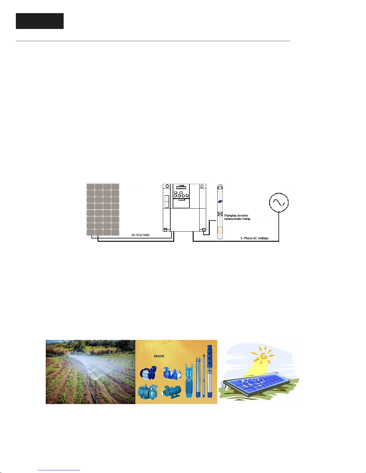
The system operates on power generated using solar PV (photovoltaic) system. The
photovoltaic array converts the solar energy into electricity, which is used for running
the motor pump set. The pumping system draws water from the open well, bore well,
stream, pond, canal etc.
The system requires a shadow-free area for installation of the Solar Panel.
Of all the ways solar electricity benefits the people on Earth, none makes as much
difference in the daily lives as pumping water. By providing water for irrigation or
potable water have obvious benefits for people in rural areas and especially for those
in developing nations. The proper choice is determined by application specific factors
like how much water is required and whether the water should be available at night
or just during high sun hours.
Solar Power and Irrigation:
Irrigation is best utilisation of Solar power
Usually area which require more water have high solar irradiation
During summer time when more water is require, there is more sun light
Water need not be available at night
Maintenance facilities are lacking, Solar pump run maintenance free.
Solar tracking can use.

Safety 2
In this chapter…
Page
Introduction
2-1
Definition and Symbol
2-3
General warning and Cautions
2-3
UL Cautions, Warning and Instructions
2-1 Safety Information
Definitions and Symbols
HAZARDOUS HIGH VOLTAGE: Motor control equipment and electronic
controllers are connected to hazardous line voltages. When servicing drives and
electronic controllers, there may be exposed components with housing or protrusions at
or above line potential. Extreme care should be taken to protect against shock. Stand on
an insulating pad and make it a habit to use only one hand when checking components.
Always work with another person in case an emergency occurs. Disconnect power before
checking controllers or performing maintenance. Be sure equipment is properly
grounded. Wear safety glasses whenever working on electronic controllers or rotating
machinery.
WARNING: This equipment should be installed, adjusted, and serviced by qualified
electrical maintenance personnel familiar with the construction and operation of the
equipment and the hazards involved. Failure to observe this precaution could result in
bodily injury.
WARNING: For equipment protection, install a ground leakage type breaker with a
fast response circuit capable of handling large currents. The ground fault protection
circuit is not designed to protect against personal injury.
WARNING: HAZARDOUS OF ELECTRICAL SHOCK. DISCONNECT INCOMING
POWER BEFORE WORKING ON THIS CONTROL.
WARNING: Wait at least five (5) minutes after turning OFF the input power supply
before performing maintenance or an inspection. Otherwise, there is the danger of
electric shock.
CAUTION: Proper grounds, disconnecting devices and other safety devices and
their location are the responsibility of the user and are not provided by Hitachi Industrial
Equipment Systems Co., Ltd.
HIGH VOLTAGE: Dangerous voltage exists until power light is OFF. Wait at least
five (5) minutes after input power is disconnected before performing maintenance
Ii
WARNING: This equipment has high leakage current and must be permanently
(fixed) hard-wire to earth ground via two independent cables.
WARNING: Rotating shafts and above-ground electrical potentials can be
hazardous. Therefore, it is strongly recommended that all electrical work conform to
the National Electrical Codes and local regulations. Installation, alignment and
maintenance should be performed only by qualified personnel.
CAUTION:
b) Any motor used must be of a suitable rating.
c) Motors may have hazardous moving path. In this event suitable protection must be
provided.
CAUTION: Hazardous (main) terminals for any interconnection (motor, contact
breaker, filter, etc.) must be inaccessible in the final installation.
CAUTION: This equipment should be installed in IP54 or equivalent enclosure.
CAUTION: Connection to field wiring terminals must be reliably fixed having
two independent means of mechanical support. Use a termination with cable support
(figure below), or strain relief, cable clamp, etc.
Ii
General Warnings and Cautions
WARNING: Never modify the unit. Otherwise, there is a danger of electric shock and/or injury.
CAUTION: Withstand voltage test and insulation resistance tests (HIPOT) are executed before
the units are shipped, so there is no need to conduct these tests before operation.
CAUTION: Do not attach or remove wiring or connectors when power is applied. Also, do not
check signals during operation.
CAUTION: Be sure to connect the grounding terminal to earth ground.
CAUTION: When inspecting the unit, be sure to wait five minutes after turning OFF the power
supply before opening the cover.
UL Cautions, Warnings and Instructions
Warnings and Cautions for Troubleshooting and Maintenance The warnings and instructions in
this section summarizes the procedures necessary to ensure an inverter installation complies with
delines.
-001L, -002L, -004L, -007L, -015S, -
022S, -004H, -007H, -015H, -022H and -030H)
WARNING: Use 75 -001S, -002S, -004S, -007S, -015L, -
022L, -037L, -055L, -075L, -110L, -150L, -040H, -055H, -075H, -110H and -150H) WARNING: Suitable
for use on a circuit capable of delivering not more than 100,000 rms Symmetrical Amperes, 240 or
480V maximum.
WARNING: When protected by CC, G, J, or R class Fuses, or when Protected By A Circuit
Breaker Having An Interrupting Rating Not Less Than 100,000 rms Symmetrical Amperes, 240 or 480
Volts Maximum.
WARNING: Install device in pollution degree 2 environment.
WARNING: Solid state motor overload protection is provided in each model
WARNING: Integral solid state short circuit protection does not provide branch circuit protection.
Branch circuit protection must be provided in accordance with the National Electric Code and any
additional local codes

Installation Preparation 3
And Requirements
In this chapter…
Page
Installation Preparation
3-1
Mounting Location
2-3
Electrical Wiring
2-3

Ii
Installation Preparation
Terminal Screw and Wire Size
Inverter Model
Screw Size
Required
Torque (N-m)
Wire Range
WJ-0001S
M3.5
1.0
AWG16
(1.3mm2)
WJ-0002S
WJ-
007S
M4
1.4
AWG14
(2.1mm2)
WJ-0015S
M4
1.4
AWG12
(3.3mm2)
WJ-0022S
M4
1.4
AWG10
(5.3mm2)
WJ-0004H
WJ-0007H
WJ-0015H
M4
1.4
AWG16
(1.3mm2)
WJ-0022H
WJ-0030H
M4
1.4
AWG14
(2.1mm2)
WJ-0040H
M4
1.4
AWG12
(3.3mm2)
WJ-0055H
WJ-0075H
M5
3.0
AWG10
(5.3mm2)
WJ-0110H
WJ-0150H
M6
5.9 to 8.8
AWG6 (13mm2)

Ii
Fuse Size
The unit shall be connected with a Listed Cartridge Nonrenewable fuse or Inverse
time circuit breaker, rated 600 Vac with the current ratings as shown in the table
below
Model No.
Fuse
Inverse Time
Circuit Breaker
Type E CMC
Type
Rating(Maximum A)
Rating (Maximum
A)
WJ-0001S
Class
J
10 A, AIC 200 kA
30A
MMS-32H,
240V,40A
WJ-0002S
Class
J
10 A, AIC 200 kA
WJ-0004S
Class
J
10 A, AIC 200 kA
WJ-0007S
Class
J
15 A, AIC 200 kA
WJ-0015S
Class
J
15 A, AIC 200 kA
WJ-0022S
Class
J
20 A, AIC 200 kA
WJ-0004H
Class
J
10 A, AIC 200 kA
20A
MMS-32H,
480V,40A or
MMS-63H,
480V,52A
WJ-0007H
Class
J
10 A, AIC 200 kA
WJ-0015H
Class
J
10 A, AIC 200 kA
WJ-0022H
Class
J
10 A, AIC 200 kA
WJ-0030H
Class
J
15 A, AIC 200 kA
WJ-0040H
Class
J
15 A, AIC 200 kA
WJ-0055H
Class
J
30 A, AIC 200 kA
40A
WJ-0075H
Class
J
30 A, AIC 200 kA
WJ-0110H
Class
J
50 A, AIC 200 kA
WJ-0150H
Class
J
50 A, AIC 200 kA
Ii
Mounting location
Hardware installation
Study the following caution messages associated with mounting the inverter. This is the
time when mistakes are most likely to occur that will result in expensive rework, equipment
damage, or personal injury.
CAUTION: Be sure to install the unit on flame-resistant material such as steel plate.
Otherwise, there is the danger of fire.
CAUTION: Be sure not to place any flammable materials near the inverter.
Otherwise, there is the danger of fire.
CAUTION: Be sure not to let the foreign matter enter vent openings in the inverter
housing, such as wire clippings, spatter from welding, metal shavings, dust, etc. Otherwise,
there is the danger of fire.
CAUTION: Be sure to install the inverter in a place that can bear the weight according
to the specifications in the text. Otherwise, it may fall and cause injury to personnel.
CAUTION: Be sure to install the unit on a perpendicular wall that is not subject to
vibration. Otherwise, it may fall and cause injury to personnel.
CAUTION: Be sure not to install or operate an inverter that is damaged or has
missing parts. Otherwise, it may cause injury to personnel.
CAUTION: Be sure to install the inverter in a well-ventilated room that does not have
direct exposure to sunlight, a tendency for high temperature, high humidity or dew
condensation, high levels of dust, corrosive gas, explosive gas, inflammable gas, grindingfluid mist, salt damage, etc. Otherwise, there is the danger of fire.
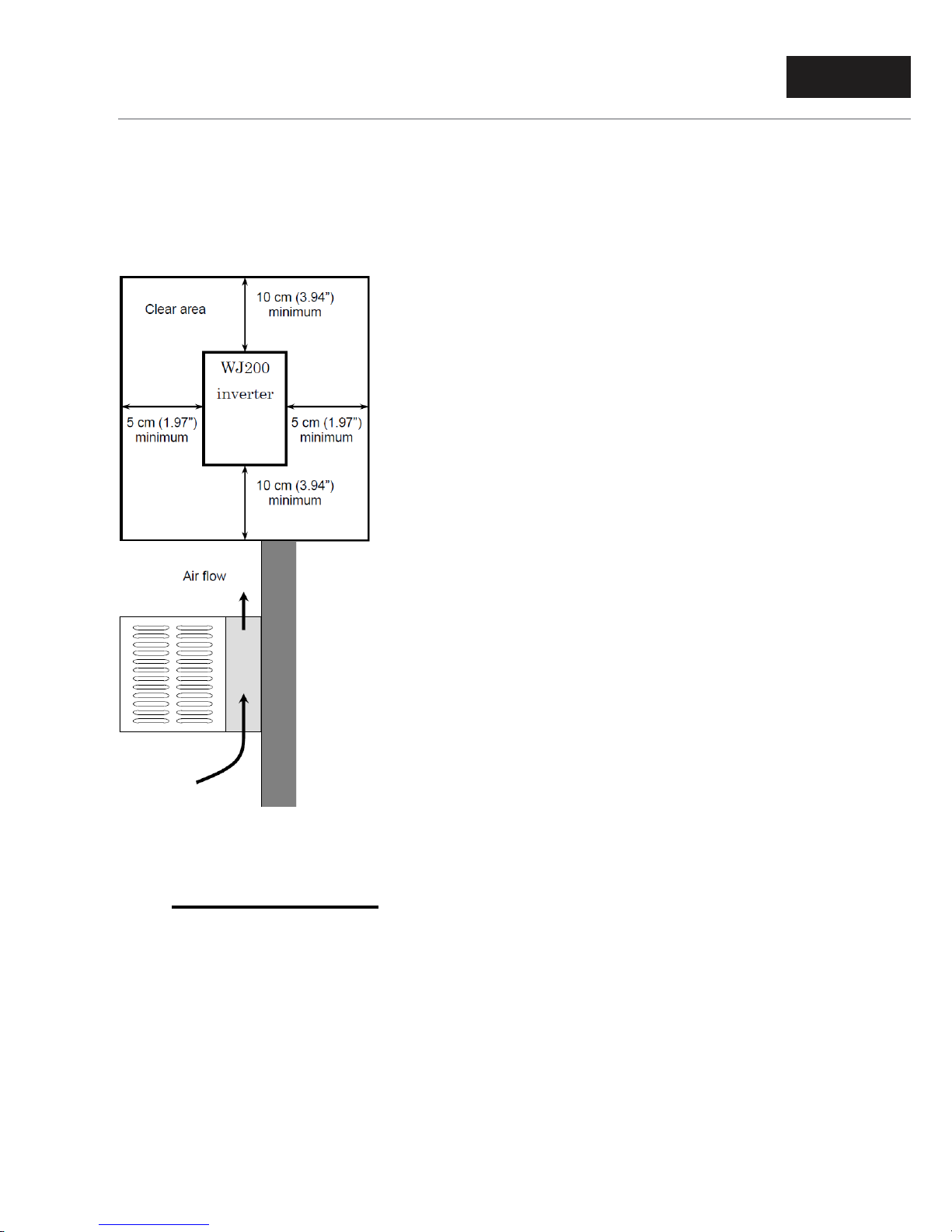
Ensure Adequate Ventilation
To summarize the caution messages – you will need to find a solid, non-flammable, vertical
surface that is in a relatively clean and dry environment. In order to ensure enough room
for air circulation around the inverter to aid in cooling, it is recommended to maintain the
specified clearance and the inverter specified in the below diagram.
CAUTION: Be sure to maintain the specified clearance area around the inverter and
to provide adequate ventilation. Otherwise, the inverter may overheat and cause equipment
damage or fire.
Ii
Ensure Adequate Ventilation
To summarize the caution messages – you will need to find a solid, non-flammable,
vertical surface that is in a relatively clean and dry environment. In order to ensure enough
room for air circulation around the inverter to aid in cooling, it is recommended to maintain
the specified clearance and the inverter specified in the below diagram
CAUTION: Be sure to maintain the specified clearance area around the inverter and to
provide adequate ventilation. Otherwise, the inverter may overheat and cause equipment
damage or fire.
Electrical Wiring
You will connect wiring to the input of the inverter. First, you must determine whether the
inverter model you have required three-phase power only, or single-phase power only. All
models have the same power connection terminals [R/L1], [S/L2], and [T/L3]. So you must
refer to the specifications label (on the side of the inverter) for the acceptable power
source types! For inverters that can accept single-phase power and are connected that
way, terminal [S/L2] will remain unconnected. Note the use of ring lug connectors for a
secure connection.

Ii
Single-phase 200V 0.1 to 0.4kW
Three-phase 200V 0.1 to 0.75kW

Ii

Ii

Solar Water System 4
Wiring details

Ii
Connection to Solar Water Pump System
DC PV Power AC Grid Power
All Type Induction motor pump and PMAC motor Pump
Hitachi Solar
Water Pump
Inverter

Ii
Power Wiring For Solar Power in Solar Water Pump Inverter
( DC Input )
SOLAR PV
MODULE DC
POWER
DC Power
Hitachi Solar Water Pump
Inverter
R S T
U V W M E
Water Submersible Pump AC
and PMAC Motor
+
-
+
-

Ii
Power Wiring For Solar Power Or Grid Power in
Solar Water Pump Inverter AC Or DC Input
Note :
When AC Grid Power and DC PV Power use with change over switch,
Alternatively AC and DC power use in Inverter
AC Grid
Power
SOLAR PV
MODULE DC
POWER
AC / DC Power
Change Over
Switch, AC MCB,
DC Fuses
Hitachi Solar Water Pump
Inverter
R
S
T
+
-
U V W M E
Water Submersible Pump AC
and PMAC Motor
Option
+
-

Ii
Power Wiring For Solar Power and Grid Power
in Solar Water Pump Inverter AC & DC Input
When AC Grid and DC PV Power use together In Inverter Where DC PV Module Total
Vmp Value should be higher than AC Grid Voltage x 1.414
AC Grid
Power
SOLAR PV
MODULE DC
POWER
Switch, AC
MCB, DC Fuses
Hitachi Solar Water Pump
Inverter
R
S
T
+
-
U V W M E
Water Submersible Pump AC
and PMAC Motor
Fuses And Diodes For
Reverse Polarity
Protection
Note :
+
-

Ii
Control Wiring for Solar Water Pump Inverter:
For Rating 0.75KW to 15KW ( WJ200 )
For Rating above 15Kw ( SJ700 )
Note:
1. For Rating 0.75kw to 15Kw, Make switch between terminal L and 1 for giving Start
command to pump and for above 15kw, It is require to put start switch between P24
and FW terminal of Control board.
2. Customer can use Push button for reset error of inverter for getting immediate
restart command.
3. There is delay restart timer inside inverter for error come while dark cloud or
suddenly power changes in PV panel. Like undervoltage
For Rating above 15Kw ( SJ700D )

Ii
Using the Front Panel Keypad
Inverter Keypad Description
Key and Indicator Legend
Items
Contents
(1) POWER
LED
Turns ON (Green) while the inverter is powered up.
(2) ALARM
LED
Turns ON (Red) when the inverter trips.
(3) Program
LED
Turns ON (Green) when the display shows changeable
parameter.
Blinks when there is a mismatch in setting.
(4) RUN LED
Turns ON (Green) when the inverter is driving the motor.
(5) Monitor
LED [Hz]
Turns ON (Green) when the displayed data is frequency related.
(6) Monitor
LED [A]
Turns ON (Green) when the displayed data is current related.
(7) Run
command LED
Turns ON (Green) when a Run command is set to the operator. (Run
key is effective.)
(8) 7-seg LED
Shows each parameter, monitors etc.
(9) Run key
Makes inverter run.
(10) Stop/reset
key
Makes inverter decelerates to a stop.
Reset the inverter when it is in trip situation
(11) ESC key
Go to the top of next function group, when a function mode is
shown
Cancel the setting and return to the function code, when a
data is shown
Moves the cursor to a digit left, when it is in digit-to-digit
setting mode
Pressing for 1 second leads to display data of d001,
regardless of current display.
(12) Up key
(13) Down key
Increase or decrease the data.
Pressing the both keys at the same time gives you the digit-to-
digit edit.
(14) SET key
Go to the data display mode when a function code is shown
Stores the data and go back to show the function code, when
data is shown.
Moves the cursor to a digit right, when it is in digit-to-digit
display mode
(15) USB
connector
Connect USB connector (mini-B) for using PC communication

Ii
SJ700 series Inverter Keypad description
Key and Indicator Legend
Name Function
Name Function
POWER lamp
Lights when the control circuit power is on.
ALARM lamp
Lights to indicate that the inverter has tripped.
RUN (operation) lamp
Lights to indicate that the inverter is operating.
PRG
(program)
lamp
Lights when the monitor shows a value set for a function.
This lamp starts blinking to indicate a warning
(when the set value is invalid).
Monitor
Displays a frequency, output current, or set value.
Monitor lamps
Indicates the type of value and units displayed on the monitor.
"Hz" (frequency), "V" (voltage), "A" (current), "kW"
(electric power), and "%" (percentage)
RUN key
enable LED
Lights up when the inverter is ready to respond to the RUN
key.
(When this lamp is on, you can start the inverter with the RUN
key on the digital
operator.)
RUN key
Starts the inverter to run the motor. This key is effective only
when the operating device is
the digital operator.
(To use this key, confirm that the operating
device indicator lamp is on.)
STOP/RESET
key
Decelerates and stops the motor or resets the
inverter from alarm status.
FUNC
(function) key
Makes the inverter enter the monitor, function, or
extended function mode.
STR (storage)
key
Stores each set value. (Always press this key
after changing a set value.)
1 (up) or 2
(down) key
Switches the inverter operation mode (among monitor,
function, and extended function
modes) or increases or decreases the value set
on the monitor for a function.

Operating Principle 5
And Hardware

Ii
Operating Principal and Hardware:
Solar Water Pump Inverter :
WJ200 & SJ700 Series of Hitachi Inverter is low voltage range AC drive and it
available for 0.4Kw to 400Kw Motor rating which is design for drawing
maximum power from PV module (Photovoltaic Cell).
Inverter has design to operate in Dual power supply AC power and DC power.
It is operating Maximum power point tracking algorithm to derive maximum power
from PV cell at any instant while in cloudy or sunny weather.
This inverter series specifically design for pump application which has special
reduce torque control mode with energy saving technology.
It is design for meet requirement of pump manufacturer and OEM to customize
application as per their requirements.
Control Mode: Reduce Torque technology is mostly utilized in pump application
where load on motor shaft have very high inertia / momentum. It operates on
starting torque is normal and afterword torque is going to reduce and increase
speed of motor. So, less power require to achieve higher speed of motor. It operate
Energy saving function while reaching nearly constant speed where optimizing input
power by reduce of output voltage and current.

Ii
MPPT overview
The Hitachi solar inverter uses maximum power pint tracking control software to
operate solar panel (PV) at maximum power generation level.
Hitachi solar inverter internal MPPT algorithm is used to derive maximum power
form PV cell at any instant and it is happen by changing output voltage and current
in PV cell until maximum power is obtained.
When inverter is in stop command then PV cell generating short circuit current and if
the PV cells are not connected to any load, then output voltage of cell is same as
open circuit voltage of PV.
See below I-V characteristic
The I-V curve is not constant for all instant, the intensity of sun ray and temperature
changes during a day time. The current changes linearly with Intensity and voltage
change very small with temperature changes. So, for constant temperature,
Maximum power varies proportionally with intensity of sun rays. The Maximum
power is obtain at knee point of I-V curve.

System Start-up 6

Ii
Parameter setting
WJ200 series Inverter parameter setting for solar water pump inverter
There are six buttons available for setting parameters.
Run button : use for start motor form operator panel/ keypad
Stop/Reset button: use for stop motor form operator panel / keypad and also to reset
alarm
ESC button: use for going back to parameter group number. Use for go out from
parameters
SET button: use for going inside of parameter and setting change value of
parameters in eeprom memory
1 UP arrow and 2 DOWN arrow button: use for changing digit value, Means change
parameter number as well as value inside parameters

Ii
WJ200 series Inverter parameter setting for solar water pump inverter
After giving power to inverter, It show 0000 value of d001 parameter (output motor Hz)
Make b049 = 01 for making inverter in Variable torque mode (Specially pump application)
Check A017 = 02 For enabling MPPT algorithm, 00 means stop, 01 means for
terminal enabling
First to set motor data inside of inverter like KW, Hz, RPM, Current, Votlage
A003 = Hz of motor
H003 = KW of motor
H004 = Pole of motor which come from RPM of motor.
A002 = 01 Terminal Run command
F002 = 100 Sec , Acceleration Time
F003 = 1 Sec , Deceleration time
A020 = Put Total Vmp of connect PV cells,
C001 = 56, Terminal 1 as Forward Run command
C006 = 18, Terminal 6 as Reset inverter
P101 = 3 min,
Auto restart delay time after inverter get any alarm, Change as per requirements
P102 = 3000, Water level sensitivity,
For 1-PHASE (2-WIRE) PUMPS MAKE :
1- P129 = 00
2- A082 = MAX
For 60Hz Pump Make :
1- A017 = 00
2- P117 = 6000
3- A061 = 60
4- A003 = 60
5- A017 = 02
Note : Make B037 = 00

Ii
SJ700 series Inverter parameter setting for solar water pump inverter
After giving power to inverter, It show 0000 value of d001 parameter (output motor Hz)
Check A017 = 01 For enabling MPPT algorithm, 00 means stop, 01 means for
terminal enabling.
And Check Short link between terminal P24 and FW where Short link seen between
PLC and CM1 terminal.
First to set motor data inside of inverter like KW, Hz, RPM, Current, Votlage
A003 = Hz of motor
H003 = KW of motor
H004 = Pole of motor which come from RPM of motor.
A002 = 01 Terminal Run command
F002 = 100 Sec , Acceleration Time
F003 = 1 Sec , Deceleration time
A020 = Put Total Vmp of connect PV cells,
C001 = 56, Terminal 1 as Forward Run command
C006 = 18, Terminal 6 as Reset inverter
P101 = 3 min,
Auto restart delay time after inverter get any alarm, Change as per requirements
P130 = 3000, Water level sensitivity,
For 60Hz Pump Make :
1- A017 = 00
2- Remove FW
3- P111 = 6000
Note : Make B037 = 00
4- A061 = 60
5- A003 = 60
6- A017 = 01
7- FW Back

Ii
SJ700D series Inverter parameter setting for solar water pump inverter
After giving power to inverter, It show 0000 value of d001 parameter (output motor
Hz)
Check A017 = 02 For enabling MPPT algorithm, 00 means stop, 02 means for
terminal enabling.
First to set motor data inside of inverter like KW, Hz, RPM, Current, Votlage
A003 = Hz of motor
H003 = KW of motor
H004 = Pole of motor which come from RPM of motor.
A002 = 01 Terminal Run command
F002 = 100 Sec , Acceleration Time
F003 = 1 Sec , Deceleration time
A020 = Put Total Vmp of connect PV cells,
C001 = 56, Terminal 1 as Forward Run command
C006 = 18, Terminal 6 as Reset inverter
P101 = 3 min,
Auto restart delay time after inverter get any alarm, Change as per requirements
P130 = 3000, Water
level sensitivity,
For 60Hz Pump Make :
A017 = 00
P111 = 6000
Note : Make B037 = 00
A061 = 60
A003 = 60
A017 = 02

Ii
Fault Codes
All fault come in parameters D081 to d086, means Hitachi drive can store last 6 fault
history.
Error
Code
Name
Cause(s)
E01
Over-current event while at
constant speed
The inverter output was short-circuited, or the
motor shaft is locked or has a heavy load. These
conditions cause excessive current for the
inverter, so the inverter output is turned OFF. The
dual-voltage motor is wired incorrectly.
E02
Over-current event during
deceleration
E03
Over-current event during
acceleration
E04
Over-current event during
other conditions
E05
Overload protection
When a motor overload is detected by the
electronic thermal function, the inverter trips and
turns OFF its output.
E06
Braking resistor overload
protection
When the BRD operation rate exceeds the
setting of "b090", this protective function shuts off
the inverter output and displays the error code.
E07
Over-voltage protection
When the DC bus voltage exceeds a threshold,
due to regenerative energy from the motor.
E08
EEPROM error
When the built-in EEPROM memory has
problems due to noise or excessive temperature,
the inverter trips and turns OFF its output to the
motor.
E09
Under-voltage error
A decrease of internal DC bus voltage below a
threshold results in a control circuit fault. This
condition can also generate excessive motor heat
or cause low torque. The inverter trips and turns
OFF its output.
E10
Current detection error
If an error occurs in the internal current detection
system, the inverter will shut off its output and
display the error code.
E11
CPU error
A malfunction in the built-in CPU has occurred,
so the inverter trips and turns OFF its output to
the motor.
E12
External trip
A signal on an intelligent input terminal
configured as EXT has occurred. The inverter
trips and turns OFF the output to the motor.
E13
USP
When the Unattended Start Protection (USP) is
enabled, an error occurred when power is applied
while a Run signal is present. The inverter trips
and does not go into Run Mode until the error is
cleared.
E14
Ground fault
The inverter is protected by the detection of
ground faults between the inverter output and the

motor upon during powerup tests. This feature
protects the inverter, and does not protect
humans.
E15
Input over-voltage
The inverter tests for input over-voltage after the
inverter has been in Stop Mode for 100 seconds.
If an over-voltage condition exists, the inverter
enters a fault state. After the fault is cleared, the
inverter can enter Run Mode again.
E21
Inverter thermal trip
When the inverter internal temperature is above
the threshold, the thermal sensor in the inverter
module detects the excessive temperature of the
power devices and trips, turning the inverter
output OFF.
E22
CPU communication error
When communication between two CPU fails,
inverter trips and displays the error code.
E25
Main circuit error (*3)
The inverter will trip if the power supply
establishment is not recognized because of a
malfunction due to noise or damage to the main
circuit element.
E30
Driver error
An internal inverter error has occurred at the
safety protection circuit between the CPU and
main driver unit. Excessive electrical noise may
be the cause. The inverter has turned OFF the
IGBT module output.
E35
Thermistor
When a thermistor is connected to terminals [5]
and [L] and the inverter has sensed the
temperature is too high, the inverter trips and
turns OFF the output.
E36
Braking error
When "01" has been specified for the Brake
Control Enable (b120), the inverter will trip if it
cannot receive the braking confirmation signal
within the Brake Wait Time for Confirmation
(b124) after the output of the brake release
signal.
E37
Safe Stop
Safe stop signal is given.
E38
Low-speed overload
protection
If overload occurs during the motor operation at a
very low speed, the inverter will detect the
overload and shut off the inverter output.
E40
Operator connection
When the connection between inverter and
operator keypad failed, inverter trips and displays
the error code.
E41
Modbus communication error
When ―trip‖ is selected (C076=00) as a
behavior in case of communication error, inverter
trips when timeout happens.
E43
EzSQ invalid instruction
The program stored in inverter memory has been
destroyed, or the PRG terminal was turned on
without a program downloaded to the inverter.
E44
EzSQ nesting count error
Subroutines, if-statement, or for-next loop are
nested in more than eight layers
E45
EzSQ instruction error
Inverter found the command which cannot be
executed.
E50
to
E59
EzSQ user trip (0 to 9)
When user –defined trip happens, inverter trips
and displays the error code.
E60
Option error (DeviceNet
Communications error)
If the disconnection due to the Bus-Off signal or
timeout occurs during the operation using
DeviceNet commands, the inverter will shut off its

output and display the error code shown on the
right. (The inverter will trip according to the
settings of "p45" and "P048".)
E61
Option error (duplicated
MACID)
If two or more devices having the same MAC ID
are detected in the same network, the inverter
will display the error code shown on the right.
E62
Option error (External trip)
If the Force Fault/Trip bit of Attribute 17 in the
Instance 1 of the Control Supervisory object is
set to "1", the inverter will shut off its output and
display the error code shown on the right.
E63
to
E68
Option error
The inverter detects errors in the option board
mounted in the optional slot. For details, refer to
the instruction manual for the mounted option
board.
E69
Option error (inverter
communication error)
If timeout occurs during the communication
between the inverter and DeviceNet option
board, the inverter will shut off its output and
display the error code shown on the right.
E80
Encoder disconnection
If the encoder wiring is disconnected, an encoder
connection error is detected, the encoder fails, or
an encoder that does not support line driver
output is used, the inverter will shut off its output
and display the error code shown on the right.
E81
Excessive speed
If the motor speed rises to "maximum frequency
(A004) x over-speed error detection level (P026)"
or more, the inverter will shut off its output and
display the error code shown on the right.
E83
Positioning range error
If current position exceeds the position range
(P072-P073), the inverter will shut off its output
and display the error code.

Ii
Motor requirement
The all type induction and submersible motor can work under Hitachi solar
inverter
200VAC Hitachi inverter can work for 0VAC to 240VAC motor
400VAC Hitachi inverter can work for 0 VDC to 460VAC motor
Motor should be three phase three wire input
DC motor can’t be work
For PMDC motor, Please contact concern Hitachi Person.

Ii
Monitoring System Data :
“D” Group parameter is use for monitor inverter data
D001 = output Hz of inverter / Speed of motor in Hz
D002 = output current to motor
D102 = DC voltage level at DC bus inside inverter
D013 = Output voltage to motor, It may be less as per energy saving mode compare
to V/F ratio
D014 = input KW power consumption
D015 = Total KW power consume by inverter/motor
D016 = Total Run time of motor in Hr
D017 = Total power on time of inverter in Hr
D018 = Heat sink temperature of inverter
PC tool for monitoring :

Ii
Maintenance and Inspection
Daily and Yearly Inspection Chart
Item Inspected
Check for…
Inspection
Cycle
Inspection
Method
Criteria
Daily
Year
Overall
Ambient
environment
Extreme
temperatures &
humidity
Thermometer,
hygrometer
Ambient temperature
between –
Humidity 90% or less
non-condensing
Major
devices
Abnormal noise
& vib.
Visual and aural
Stable environment for
electronic controls
Power
supply
voltage
Voltage tolerance
Digital volt meter,
measure
between inverter
terminals [L1],
[L2], [L3]
200V class: 50/60 Hz
200 to 240V (-15/+10%)
400V class: 50/60 Hz
380 to 460V (-15/+10%)
Main
circuit
Ground
Insulation
Adequate
resistance
5 Mohm or greater
Mounting
No loose screws
Torque wrench
M3.5: 1.0Nm M4: 1.4Nm
M5: 3.0 M6: 3.9 to
5.1Nm M8: 5.9 to 8.8Nm
Components
Overheating
Thermal trip
events
No trip events
IGBT
Resistance value
Terminal
block
Secure
connections
Visual
No abnormalities
Smoothing
capacitors
Leaking, swelling
Visual
No abnormalities
Relay(s)
Chattering
Aural
Single click when
switching ON or OFF
Resistors
Cracks or
discoloring
Visual
Check Ohms of optional
braking res.
Control
circuit
Function
Voltage balance
between phases
Measure voltage
between U,V,W
Difference must be 2%
or less.
Protection circuit
e.g. Input Ex.trip
signal and check
inverter behavior
and alarm signal.
Functions properly.
Overall
No odor,
discoloring,
corrosion
Visual
No abnormalities
Capacitor
Leaking, swelling
Visual
Undistorted appearance
Cooling
Cooling fan
Noise
Power down,
manually rotate
Rotation must be
smooth
Dust
Visual
Vacuum to clean
Mounting
Visual
Mounted firmly
Heat sink
Dust
Visual
Vacuum to clean
Display
LEDs
Legibility
Visual
All LED segments work

Ii
Note 1: The life of a capacitor is affected by the ambient temperature.
Note 2: Designed life of a cooling fan is.10 years. However, it is affected by the ambient
temperature and other environmental conditions.
Note 3: The inverter must be cleaned periodically. If dust accumulates on the fan and heat sink,
it can cause overheating of the inverter.

Network Communication 7

Ii
Modbus Network Communication
Introduction
WJ200 Series inverters have built-in RS-485 serial communications, featuring the Modbus
RTU protocol. The inverters can connect directly to existing factory networks or work with
new networked applications, without any extra interface equipment. The specifications are
in the following table.
Item
Specifications
User-selectable
Transmission speed
2400 / 4800 / 9600 / 19.2k / 38.4k /
57.6k / 76.8k / 115.2k bps
Communication mode
Asynchronous
Character code
Binary
LSB placement
Transmits LSB first
Electrical interface
RS-485 differential transceiver
Data bits
8-bit (Modbus RTU mode)
Parity
None / even / odd
Stop bits
1 or 2 bits
Startup convention
One-way start from host device
Wait time for response
0 to 1000 msec.
Connections
Station address numbers from 1 to 32
Connector
Terminal connector
Error check
Overrun, Framing block check code,
CRC-16, or horizontal parity
Cable length
500m maximum
Connecting the Inverter to Modbus
Modbus connector is in control terminal block as below. Note that RJ45 connector (RS-422)
is used for external operator only.

Ii
Inverter Parameter Setup –
The inverter has several settings related to Modbus communications. The table
below lists them together. The Required column indicates which parameters must
be set properly to allow communications. You may need to refer to the host
computer documentation in order to match some of its settings.
Func.
Code
Name
Required
Settings
A001
Frequency source
03
00…Keypad potentiometer
01…Control terminal
02…Function F001 setting
03…Modbus network input
10…Calculate function output
A002
Run command source
03
01…Control terminal
02…Run key on keypad, or digital
operator
03…Modbus network input
C071
Communication speed
05
03 2400 bps
04 4800 bps
05 9600 bps
06 19.2k bps
07 38.4k bps
08 57.6k bps
09 76.8k bps
10 115.2k bps
C072
Modbus Address
1
Network address, range is 1 to
247
C074
Communication parity
00
00…No parity
01…Even parity
02…Odd parity
C075
Communication stop bit
1
Range is 1 or 2
C076
Communication error
select
00
00…Trip (Error code E60)
01…Decelerate to a stop and trip
02…Disable
03…Free run stop (coasting)
04…Decelerate to a stop
C077
Communication error
time-out
1.00
Comm. Watchdog timer period,
range is 0.00 to 99.99 sec.
C078
Communication wait
time
10
Time the inverter waits after
receiving a message before it
transmits. Range is 0. to 1000.
ms

Ii
NOTE:
When you change any of the parameters above, the inverter power must be
rebooted in order to activate new parameters. Instead of rebooting, turning ON/OFF
of reset terminal works as same.
For Modbus data Listing, Please refer detail manual come with inverter
Common Fault and Remedies
Fault: During running pump Find E09.x – Under Voltage Alarm
Remedies: First to check x value,
Suppose E09.2, E09.3 and E09.4 means during deceleration, Constant speed and
acceleration condition
Then Check following parameters
F002 – 50second
F003 – 10 second
A017 – 02 MPPT enable
D004 – DC voltage of PV input power
Fault: If find E07.x – Over Voltage Alarm
Remedies: First to check PV module Open circuit Voltage (Voc) value and no of PV
connected in series connection. If Total Voc value is higher than 800VDC then
Inverter will show over voltage alarm. then try to reduce PV qty in series.
Now, Best selection as below for series and parallel connection
Example: If, Pump motor voltage is 415VAC, Then try to make Total Vmp value of
connected near to 585 to 600VDC. It should be 1.414 time of Pump motor voltage
Fault: If find E01, E02, E03, E04 and E05 during starting of pump
Remedies: Check following parameters
F002 – 50 second (Up to 90kw inverter)
B021 – 03 overload restriction enable
A044 – 01 Pump control mode
Try to change B049 – 01 VT mode, B022 – max value and B023 – 0.1sec
Fault: If find E14 – Ground fault
Remedies: Check motor wires and its earth cable.
Inverter has two screw terminal One cable for incoming and other for motor earth
cable
If Earthing cable is properly connected then check inverter to pump motor distance,
if it more than 100meter, please try to use output line reactor (output choke) with
minimum 3% impedance.
If there is no any motor cable and only DC power input, then asked to service
person from company.

Application Notes
FOR Best Vmpp value to set in
A020 : D004 (VOC )/1.2 OR
D004 (VOC )VOC/1.25
PV in Series
PV in
Parallel
Ii

Standard Specications
1-phase 200V class
Models WJ2 00- 00 1SF 002SF 004SF 007SF 0 15 S F 022SF
VT 0.2 0.4 0.55 1.1 2.2 3.0
kW
Applicable mot or size *
Rated capaci ty (kVA)
Input
Rating
Output
Rating
Minimum value of r esistor (Ω) 100 100 100 50 50 35
Weight
Rated input volt age (V ) 1-phase: 20 0V-15% to 240V +10%, 5 0/ 60Hz ±5%
Rated inpu t current (A)
Rated output voltage (V) *
Rated output current (A)
1
3-phase 200V class
Models WJ2 00- 001LF 002LF 004LF 007LF 015 LF 022LF 037LF 055LF 075LF 110 LF 150 LF
Applicable mot or size *
Rated capaci ty (kVA)
Input
Rating
Output
Rating
Minimum value of r esistor (Ω) 100 10 0 10 0 50 50 35 35 20 17 17 10
Weight
Rated input volt age (V ) 3-phase: 200V-15% to 240V +10%, 5 0/ 60Hz ±5%
Rated inpu t current (A)
Rated output voltage (V) *
Rated output current (A)
1
CT 0.1 0.2 0.4 0.75 1.5 2.2
VT 1/4 1/ 2 3/4 1. 5 3 4
HP
CT 1/8 1/4 1/2 1 2 3
VT 0.4 0.6 1.2 2.0 3.3 4.1
200V
CT 0.2 0.5 1.0 1.7 2.7 3.8
VT 0.4 0.7 1.4 2.4 3.9 4.9
240V
CT 0.3 0.6 1.2 2.0 3.3 4.5
VT 2.0 3.6 7.3 13.8 20.2 24.0
CT 1.3 3.0 6.3 11.5 16.8 22.0
2
VT 1. 2 1.9 3.5 6.0 9.6 12.0
CT 1.0 1.6 3.0 5.0 8.0 11.0
kg 1.0 1. 0 1.1 1.6 1.8 1.8
lb 2.2 2.2 2.4 3.5 4.0 4.0
VT 0.2 0.4 0.75 1.1 2.2 3.0 5.5 7. 5 11 15 18.5
kW
CT 0 .1 0.2 0.4 0.75 1.5 2.2 3.7 5.5 7. 5 11 15
VT 1/4 1/2 1 1.5 3 4 7.5 10 15 20 25
HP
CT 1/8 1/4 1/2 1 2 3 5 7.5 10 15 20
VT 0.4 0.6 1.2 2.0 3.3 4.1 6.7 10.3 13.8 19 .3 23.9
200V
CT 0.2 0.5 1.0 1.7 2.7 3.8 6.0 8.6 11. 4 16.2 20.7
VT 0.4 0.7 1. 4 2.4 3.9 4.9 8.1 12.4 16.6 23.2 28.6
240V
CT 0.3 0.6 1.2 2.0 3.3 4.5 7.2 10.3 13.7 19.5 24.9
VT 1.2 1.9 3.9 7. 2 10.8 13.9 23.0 3 7.0 48.0 68.0 72.0
CT 1.0 1.6 3.3 6.0 9.0 12.7 20.5 30.8 39.6 57.1 62.6
2
VT 1.2 1.9 3.5 6.0 9.6 12.0 19.6 30.0 40.0 56.0 69.0
CT 1.0 1.6 3.0 5.0 8.0 11.0 17.5 25.0 33.0 47.0 60.0
kg 1.0 1.0 1.1 1. 2 1. 6 1.8 2.0 3.3 3.4 5.1 7. 4
lb 2.2 2.2 2.4 2.6 3.5 4.0 4.4 7.3 7. 5 11. 2 16.3
3-phase: 200 to 240V (proportional to input voltage)
3-phase: 200 to 240V (proportional to input voltage)
Ii
3-phase 400V class
Models WJ2 00- 00 4HF 007HF 015HF 02 2HF 030HF 040HF 055HF 0 75HF 110HF 150HF
VT 0.75 1.5 2.2 3.0 4.0 5.5 7. 5 11 15 18.5
kW
Applicable mot or size *
Rated capaci ty (kVA)
Input
Rating
Output
Rating
Minimum value of r esistor (Ω) 180 18 0 180 100 100 100 70 70 70 35
Weight
Rated input volt age (V ) 3-phase: 380V-15% to 480 V +10%, 50 / 60Hz ±5%
Rated inpu t current (A)
Rated output voltage (V) *
Rated output current (A)
1
CT 0.4 0.75 1. 5 2.2 3.0 4.0 5.5 7.5 11 15
VT 1 2 3 4 5 7.5 10 15 20 25
HP
CT 1/2 1 2 3 4 5 7.5 10 15 20
VT 1. 3 2.6 3.5 4.5 5.7 7.3 11. 5 15 .1 20.4 25.0
200V
CT 1.1 2.2 3.1 3.6 4.7 6.0 9.7 11. 8 15.7 20.4
VT 1. 7 3.4 4.4 5.7 7. 3 9.2 14. 5 19 .1 25.7 31. 5
240V
CT 1.4 2.8 3.9 4.5 5.9 7.6 12. 3 14.9 19.9 25.7
VT 2.1 4.3 5.9 8.1 9.4 13. 3 20.0 24.0 38.0 4 4.0
CT 1. 8 3.6 5.2 6.5 7. 7 11.0 16.9 18. 8 29.4 35.9
2
VT 2.1 4.1 5.4 6.9 8.8 11.1 17.5 23.0 31.0 38.0
CT 1. 8 3.4 4.8 5.5 7. 2 9.2 14.8 18.0 24.0 31.0
kg 1. 5 1.6 1. 8 1.9 1. 9 2 .1 3.5 3.5 4.7 5.2
lb 3.3 3.5 4.0 4.2 4.2 4.6 7.7 7.7 10.4 11. 5
3-phase: 380 to 480 V (proportional to input voltage)

General Specications
Item General Specications
Protect ive housing *
3
Control method Sinusoidal Pulse Width Modulation (PW M) control
Carrier frequency 2kHz to 15kHz (derating required depending on the model)
Output f requency range *
4
Frequency accuracy
Frequency set ting resolut ion Digital: 0.01Hz; Analog: max . frequency / 1000
Volt ./ Freq. character istic
Overload capacity
Acceleration /deceleration time 0.01 to 3600 seconds, linear and S-curve accel /decel, second accel /decel setting available
Start ing torque 200% @0.5Hz (sensorless vector control)
DC braking Variable operating f requency, time, and braking force
Operator panel
Freq . setting
Ex ternal signal *
Via network RS485 ModBus RTU, other net work option
Operator panel Run /Stop (For ward /Rever se run change by command)
FW D/ REV run
Ex ternal signal *
Via network RS485 ModBus RTU, other net work option
Terminals 7 terminals, sink / source changeable by a short b ar
Intelligent input
Input signal
terminal
68 funct ions
Functions
assignable
Intelligent output
terminal
Functions
48 f unctions
assignable
Output signal
Moni tor output (analog) Output freq., output current, output torque, output voltage, input power, thermal load ratio, L AD freq., heat sink temperature, general ou tput (EzSQ)
Pulse train output
(0 – 10VDC, 32 kHz max.)
Alar m output cont act ON for inverter alar m (1c contacts, both nor mally open or closed available.)
Other functions
Protect ive funct ion
Temperature Operating (ambient): -10 to 50
Operating environment
Humidity 20 to 90% humidity (non-condensing)
Vibration *
Location Altitude 1,000m or less, indoors (no corrosive gasses or dust)
Coat ing color Black
Options Remote operator unit, cables for the units, braking unit, braking resistor, AC reactor, DC reactor, EMC lter
IP20
0.1 to 400Hz
Digital command: ±0.01% of the maximum frequency
Analog command: ±0.2% of the maximum frequency (25
°
C ±10°C)
V/f control (constant torque, reduced torque, free-V /F): b ase freq. 3 0Hz – 400Hz adjustable,
Sensorless vector control, Closed loop control with motor encoder feedback (only V/f control).
Dual rating: CT (Heavy duty): 60 sec. @150%
VT (Normal duty): 60 sec. @120%
2
1
keys / Value set tings
6
0 to 10 VDC (input impedance 10kΩ), 4 to 20mA (input imp edance 100Ω), Potentiometer (1k to 2kΩ, 2W )
6
Forward r un /stop, Reverse run / stop
FW (forward run command), RV (reverse run command), CF1 – CF4 (multi-stage speed setting), JG (jog command), DB (external braking), SET (set second
motor), 2CH (2-stage accel. /decel. command), FRS (free run stop command), E XT (exter nal trip), USP (st artup function), CS (commercial power switchover),
SFT (soft lock), AT (analog input selection), RS (reset), PTC (thermistor thermal protection), STA (start), STP (stop), F/ R (forward /reverse), PID (PID
disable), PIDC (PID reset), UP (remote control up function), DWN (remote control down function), UDC (remote control data clear), OPE (operator control),
SF1– SF7 (multi-stage speed setting; bit operation), OLR (overload restriction), TL (torque limit enable), TRQ1 (torque limit changeover1), TRQ2 (torque
limit changeover2), BOK (Braking conrmation), L AC (LAD cancellation), PCLR (position deviation clear), ADD (add frequency enable), F-TM (force terminal
mode), ATR (permission of torque command input), KHC (Cumulative power clear), MI1– MI7 (general purpose inputs for EzSQ), AHD (analog command hold),
CP1– CP3 (multistage-position switches), ORL (limit signal of zero-return), ORG (trigger signal of zero-return), SPD (speed/position changeover), GS1,GS2 (STO
inputs, safety related signals), 485 (Starting communication signal), PRG (executing E zSQ program), HLD (retain output frequency), ROK (permission of run
command), EB (rotation direction detection of B-phase), DISP (display limitation), NO (no function)
RUN (run signal), FA1 –FA 5 (frequency arrival signal), OL,OL2 (overload advance notice signal), OD (PID deviation error signal), A L (alarm signal),
OTQ (over / under torque thre shold), UV (under-voltage), TRQ (torque limit signal), RNT (run time expired), ONT (power ON time expired), THM (thermal
warning), BRK (brake release), BER (brake error), ZS (0Hz detection), DSE (speed deviation excessive), POK (positioning completion), ODc (analog
voltage input disconnection), OIDc (analog cur rent input disconnection), FB V (PID second stage output), NDc (network disconnec t detection), LOG1 –
LOG3 (Logic output signals), WAC (capacitor life warning), WA F (cooling fan warning), FR (st arting contact), OHF (heat sink overheat warning), LOC
(Low load), MO1 –MO3 (general outputs for EzSQ), IRDY (inver ter ready), FWR (forward operation), RVR (reverse operation), M JA (major failure),
WCO (window comparator O), WCOI (window comparator OI), FREF (frequency command source), REF (run command sour ce), SETM (second motor in
operation), EDM (STO (safe torque off ) per formance monitor), OP (option control signal), NO (no function)
[PW M output]
Output fre q., output current, output torque, output voltage, input power, thermal load ratio, LAD freq., heat sink temperature, general output (EzSQ)
[Pulse train output]
Output frequency, output cur rent , pulse train input monitor
Free-V/f, manual / automatic torque boost, output voltage gain adjustment, AVR function, reduced voltage start, motor data selection, autotuning, motor stabilization control, reverse r unning protection, simple position control, simple torque control, torque limiting, automatic carrier
frequency r educ tion, energy saving operation, PID function, non-stop operation at instantaneous power failure, brake control, DC inje ction
braking, dynamic braking (BRD), f requency upper and lower limiters, jump frequencies, curve accel and decel (S, U, inversed U,EL-S), 16-stage
speed prole, ne adjustment of st art frequency, accel and decel stop, process jogging, frequency calculation, frequency addition, 2-stage
accel/decel, stop mode selection, start /end freq., analog input lter, window comparators, input terminal response time, output signal delay/
hold function, rotation direction restriction, stop key sele ction, sof tware lock, safe stop function, scaling function, display restriction, passwor d
function, user p arameter, initialization, initial display selection, cooling fan control, warning, trip retry, frequency pull-in r estart, frequency
matching, overload restriction, over current restriction, DC bus voltage AVR
Over-current, over-voltage, under-voltage, overload, brake resistor overload, CPU error, memory error, external trip, USP error, ground fault detection
at power on, temperature error, internal communication error, driver error, thermistor error, brake error, safe stop, overload at low speed, modbus
communication error, option error, encoder disconnection, speed excessive, EzSQ command error, EzSQ nesting error, EzSQ execution error, EzSQ user trip
°
C / Stor age: -2 0 to 65°C *
8
5.9m/s2 (0.6G), 10 to 55 Hz
7
Ii
 Loading...