

Page 1
MODELS
W 6VM
W 6V4
W 6VA4
SCREW DRIVER
W 6VM
W 6V4
W 6VA4
Hitachi
Power Tools
TECHNICAL DATA
AND
SERVICE MANUAL
LIST Nos. W 6VM: 0798
W 6V4: E701
W 6VA4: E702
W
Nov. 2004
SPECIFICATIONS AND PARTS ARE SUBJECT TO CHANGE FOR IMPROVEMENT
Page 2
REMARK:
Throughout this TECHNICAL DATA AND SERVICE MANUAL, a symbol(s)
is(are) used in the place of company name(s) and model name(s) of our
competitor(s). The symbol(s) utilized here is(are) as follows:
Model W 6VM
Competitor
Symbol Utilized
Company Name
Model Name
Model W 6V4
Symbol Utilized
C
P
C
B
P
MAKITA
DeWALT
Company Name
MAKITA
BOSCH
DeWALT
DW255 (DW275K)
Competitor
1404VSR (GSR6-40TE)
6825
Model Name
6824
DW272
Model W 6VA4
Symbol Utilized
Competitor
Company Name
C
B
E
MAKITA
BOSCH
Milwaukee
Model Name
6823
1405VSR (GSR6-25TE)
6740-20
Page 3

CONTENTS
Page
1. PRODUCT NAME ............................................................................................................................ 1
2. MARKETING OBJECTIVE .............................................................................................................. 1
3. APPLICATIONS ............................................................................................................................... 1
4. SELLING POINTS ........................................................................................................................... 1
4-1. Selling Point Descriptions ................................................................................................................ 2
5. SPECIFICATIONS ........................................................................................................................... 6
5-1. Specifications ....................................................................................................................................6
5-2. Optional Accessories ........................................................................................................................7
6. COMPARISONS WITH SIMILAR PRODUCTS ............................................................................... 8
6-1. W 6VM ..............................................................................................................................................8
6-2. W 6V4 ...............................................................................................................................................8
6-3. W 6VA4 .............................................................................................................................................8
7. PRECAUTIONS IN SALES PROMOTION ...................................................................................... 9
7-1. Handling Instructions ........................................................................................................................9
7-2. Caution Plates .................................................................................................................................. 9
7-3. Screw Driving-depth Adjustment.......................................................................................................9
7-4. Self-drilling Screws .........................................................................................................................10
7-5. Drywall Screws ...............................................................................................................................10
7-6. Variable-speed Switch .................................................................................................................... 11
8. PRECAUTIONS IN DISASSEMBLY AND REASSEMBLY ........................................................... 12
8-1. Disassembly ...................................................................................................................................12
8-2. Reassembly ....................................................................................................................................13
8-3. Wiring Diagrams .............................................................................................................................15
8-4. Internal Wire Arrangement and Wiring Work ..................................................................................16
8-5. Insulation Tests ...............................................................................................................................17
8-6. No-load Current Values ................................................................................................................... 18
9. STANDARD REPAIR TIME (UNIT) SCHEDULES ........................................................................ 19
Assembly Diagram for W 6VM
Assembly Diagram for W 6V4
Assembly Diagram for W 6VA4
Page 4
1. PRODUCT NAME
Hitachi Screw Driver, Models W 6VM, W 6V4 and W 6VA4
2. MARKETING OBJECTIVE
The Models W 6V4 and W 6VA4 screw drivers are upgraded versions of the current Models W 6V3 and W 6VA3,
equipped with strong aluminum gear cover and inner cover and ergonomical housing and handle cover with soft
grip. The Model W 6VM screw driver is newly added to respond to the increasing market demand for a screw
driver operable at 6,000 rpm. Our market share is expected to grow with the release of these new models which
broaden our lineup of screw drivers.
3. APPLICATIONS
Drywall screws: Fastening metal studs and drywall
Interior construction Installation of ceilings, paneling or partitions in offices, shops
supermarkets, apartment houses, schools, factories, etc.
Hex. and Teks screws: Fastening metal to metal, or metal to wood
Exterior construction Installation of siding on buildings
Installation of galvanized iron sheet or corrugated sheet roofing
Plate assembly Assembly and mounting of advertising billboards
Various other interior/exterior construction and plate assembly jobs
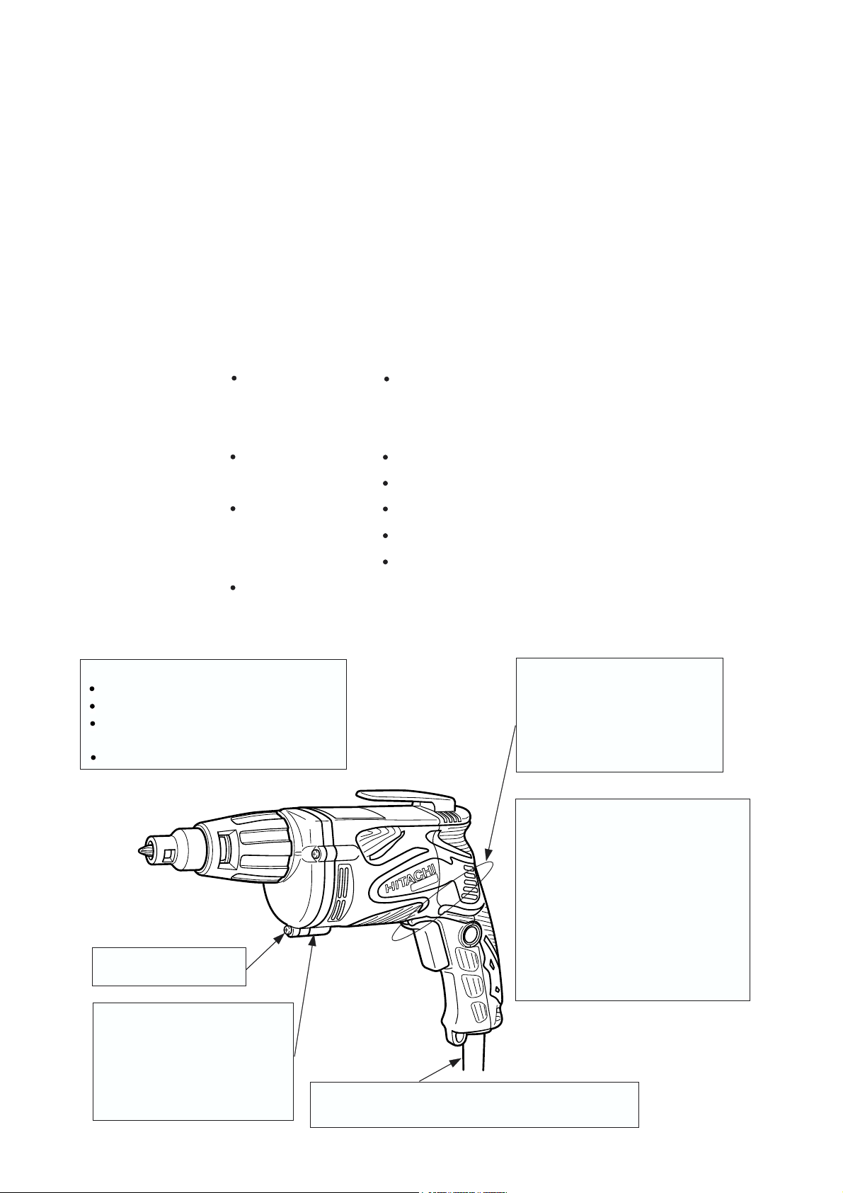
4. SELLING POINTS
Ergonomical design for better operation
Soft grip housing and handle cover
Big switch trigger
Soft protect cover on gear cover and
inner cover
One motion detachable locator
Robust aluminum gear
cover and inner cover
Assembly of metal frames for vinyl greenhouses
Assembly and installation of automobile stamped sections
Class-top short length of grip
portion 206 mm (8-1/8")
C: 212 mm (8-11/32")
B: 210 mm (8-1/4")
P: 210 mm (8-1/4")
E: 208 mm (8-3/16")
High-power motor:
Class-top power input
•••
U.S.A., Canada: 750 W
Other countries: 620 W
C: U.S.A., Canada: 710 W
Other countries: 570 W
B: U.S.A., Canada: 550 W
Other countries: 500 W
P: U.S.A., Canada: 740 W
Other countries: 540 W
E: U.S.A., Canada: 740 W
Class-top low noise 76 dB (A)
C: 79 dB (A)
B: 78 dB (A)
P: 82 dB (A)
E: 80 dB (A)
(Rotation direction is R.)
7.5 m (24.6 ft.) long cord
(for U.S.A., Canada, Europe, Russia and Oceania)
--- 1 ---
Page 5
4-1. Selling Point Descriptions
The new Models W 6VM, W 6V4 and W 6VA4 are more comfortable and easier to operate than the current
models and competitors. The outstanding selling points are as follows.
1) Short length of grip portion
The Models W 6VM, W 6V4 and W 6VA4 have a
handle that is shaped in good weight balance
according to the ergonomical design. In addition,
the length of the grip portion is shortest in the
class. The handle grip is very comfortable and it
efficiently reduces operator fatigue. Table 1
shows a comparison of the length of grip portion.
Table 1 Comparison of the length of grip portion
Maker
Model
The length of grip portion mm
HITACHI
W 6VM
206 (8-1/8")
Maker
Model
The length of grip portion mm
W 6V4
206 (8-1/8")
212 (8-11/32")
HITACHI
218 (8-19/32")
(Measuring point of the length of grip portion)
Measuring point of the
length of grip portion
C
P
210 (8-1/4")
W 6V3
CB
210 (8-1/4")212 (8-11/32")
P
210 (8-1/4")
Maker
Model
The length of grip portion mm
W 6VA4
206 (8-1/8")
HITACHI
218 (8-19/32")
W 6VA3
CB
210 (8-1/4")212 (8-11/32")
208 (8-3/16")
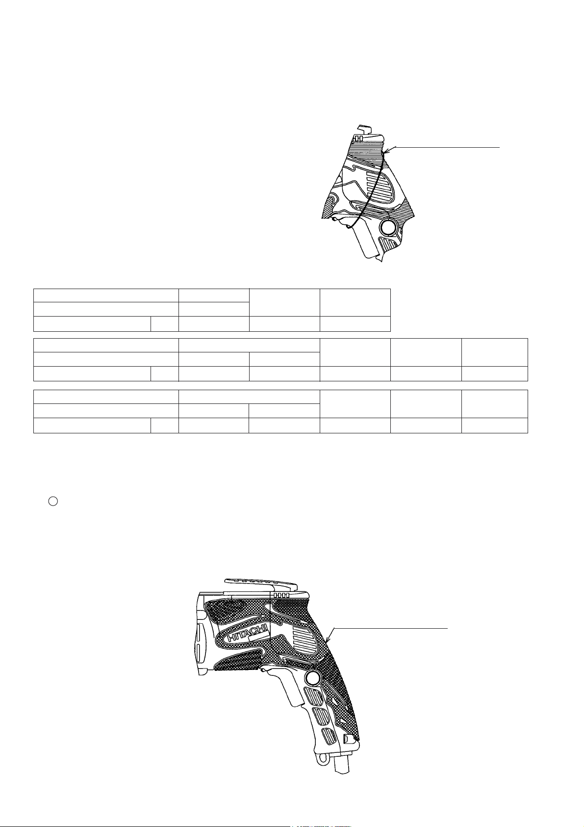
2) Ergonomical design for better operation
The Models W 6VM, W 6V4 and W 6VA4 are equipped with the following four parts as a result of pursuance of
the ergonomical design.
1
Soft grip housing and handle cover
The entire body is covered with the uniquely designed elastomer and the grip portion is uneven and matte-
finished to make it resistant to slipping. Thus the grip is very comfortable and it efficiently reduces operator
fatigue.
(Range covered with elastomer)
Crosshatched portion:
Covered with elastomer
E
--- 2 ---
Page 6
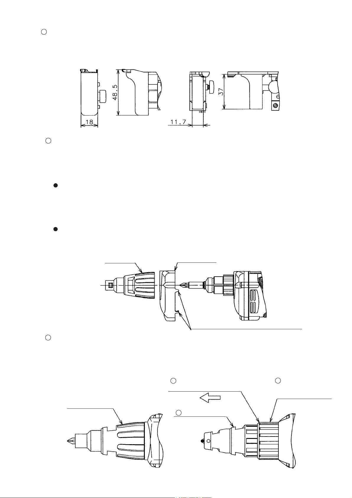
2
Big switch trigger
A new big switch trigger is adopted for easier switch operation. The switch trigger is rounded for better feel
of triggering.
W 6V4
3
Soft protect cover on gear cover and inner cover
W 6V3
A transparent protect cover made of elastomer is added to cover the surfaces of the gear cover and the
inner cover made of aluminum. It is easily detachable just by removing the locator. The protect cover has
the following two features.
The material of the protect cover has extremely lower thermal conductivity than aluminum. Therefore,
the protect cover lessens feeling of coldness or hotness even if the gear cover is touched with bare
hands under the severe temperature environment such as in the severely cold areas (Russia, Eastern
Europe and Northern Europe) or the severely hot areas (Middle East and South-East Asia).
The protect cover is soft because it is made of elastomer. In addition, the aluminum gear cover protects
from damages even if the Models W 6VM, W 6V4 and W 6VA4 are hit against wall materials.
(Mounting the protect cover)
Locator
Protect cover
Engage the claws in the air vents of the
housing to secure the protect cover.
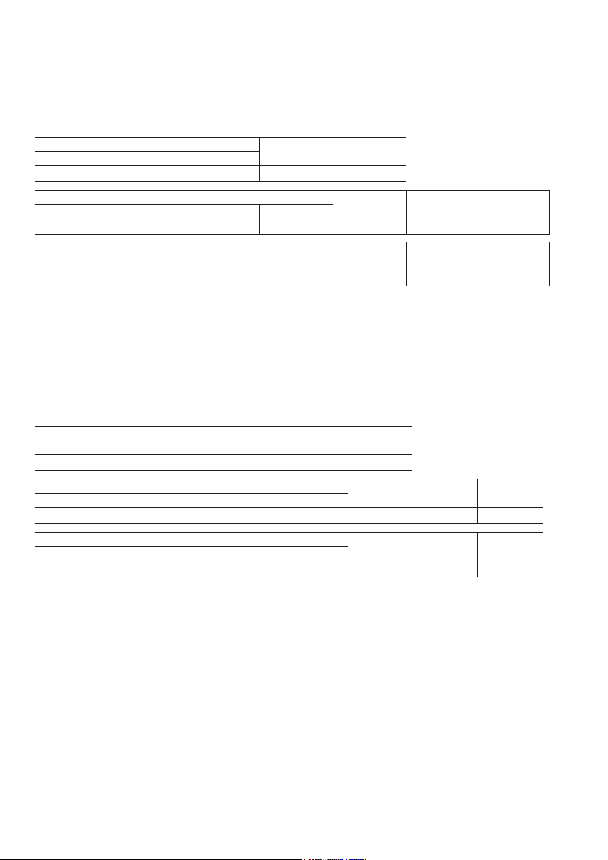
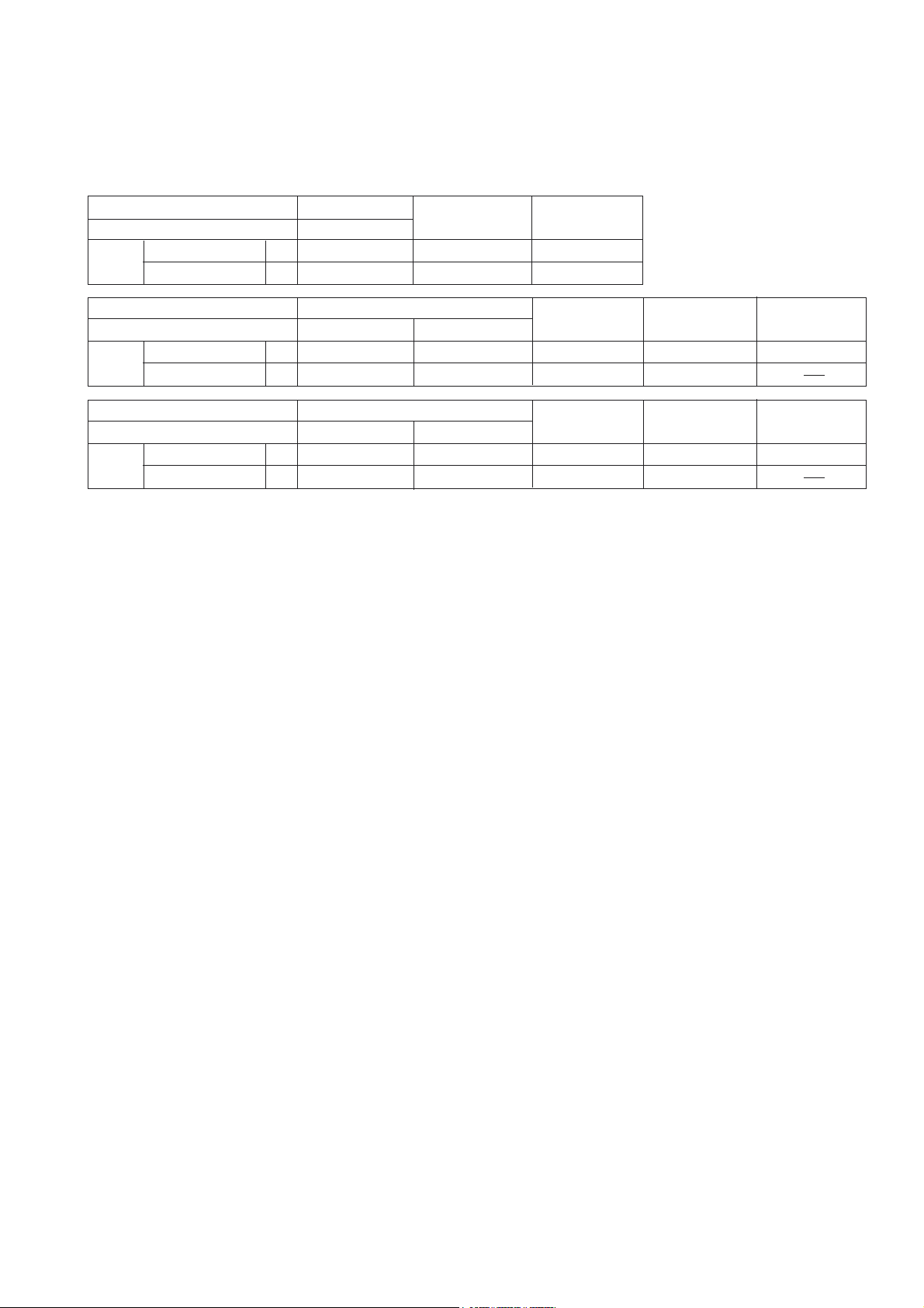
4
One motion detachable locator
The locator is used for adjusting the screw head depth. The current Models W 6V3 and W 6VA3 require
the operator to pull the lock sleeve and turn the locator for adjustment. The Models W 6VM, W 6V4 and
W 6VA4 are easier to adjust just by turning the locator.
1
W 6V4
Pull the lock sleeve in
the arrow direction.
W 6V3
3
Push the lock
sleeve in the gear
cover.
Turn the locator.
2
Turn the locator.
--- 3 ---
Page 7
3) Low noise
A new fan developed by the 3-D digital analysis technology is adopted. Thanks to the optimized air passage,
the noise level of the Models W 6VM, W 6V4 and W 6VA4 is the lowest in the class. Table 2 shows a
comparison of the no-load noise level.
Table 2 Comparison of the no-load noise level
Maker
Model
No-load noise level* dB (A)
Maker
Model
No-load noise level* dB (A)
Maker
Model
No-load noise level* dB (A)
*: Rotational direction is R.
4) Robust aluminum gear cover and inner cover
The Models W 6VM, W 6V4 and W 6VA4 have the gear cover and the inner cover made of aluminum, while
those of the current Models W 6V3 and W 6VA3 are made of resin. This is to ensure the specified durability
and strength of the Models W 6VM, W 6V4 and W 6VA4 even under the severe environment. Table 3 shows a
comparison of the material of gear cover and inner cover.
Table 3 Comparison of the material of gear cover and inner cover
Maker
Model
Material of gear cover and inner cover
HITACHI
W 6VM
76
W 6V4
76
W 6VA4
76
HITACHI
W 6VM
Aluminum
HITACHI
HITACHI
CP
79
W 6V3
79
W 6VA3
79
C
Aluminum
82
C
79
C
79
P
Plastic
B
78
B
78
P
82
E
80
Maker
Model
Material of gear cover and inner cover
Maker
Model
Material of gear cover and inner cover
5) 7.5 m (24.6 ft.) long cord (for U.S.A., Canada, Europe, Russia and Oceania)
The 7.5 m (24.6 ft.) long cord of the Models W 6VM, W 6V4 and W 6VA4 eliminates the inconvenience of
connecting an extension cord or carrying a cord reel in the work site.
Aluminum
W 6VA4
Aluminum
W 6V4
HITACHI
HITACHI
W 6V3
Plastic
W 6VA3
Plastic
C
Aluminum
C
Aluminum
B
Plastic
B
Plastic
P
Aluminum
E
Aluminum
--- 4 ---
Page 8
6) High power motor
The motor of the Models W 6VM, W 6V4 and W 6VA4 is more powerful than the current Models W 6V3 and
W 6VA3 with the class-top power input. Table 4 shows a comparison of the power input.
Table 4 Comparison of the power input
Maker
Model
Power
input
Maker
Model
Power
input
Maker
Model
Power
input
U.S.A., Canada
Other areas
U.S.A., Canada
Other areas
U.S.A., Canada
Other areas
HITACHI
W 6VM
750 (120 V, 6.6 A)
W
W
W 6V4
750 (120 V, 6.6 A)
W
W
W 6VA4
750 (120 V, 6.6 A)
W
W
620
620
620
710 (115 V, 6.5 A)
HITACHI
680 (115 V, 6.4 A)
HITACHI
W 6VA3
680 (115 V, 6.4 A)
CB
680 (120 V, 6.0 A)
570
W 6V3
600
600
540
CB
710 (115 V, 6.5 A)
570
CB
710 (115 V, 6.5 A)
570
550 (120 V, 4.8 A)
500
550 (120 V, 4.8 A)
500
P
720 (120 V, 6.3 A)
E
740 (120 V, 6.5 A)
--- 5 ---
Page 9
5. SPECIFICATIONS
5-1. Specifications
Model
Capacity
Bit mounting size
Power source
Type of motor
Full-load current
Power input
No-load rotation
Enclosure
Drywall screw
Self-drilling screw
U.S.A., Canada
Other areas
U.S.A., Canada
Other areas
W 6VM
6.35 mm (1/4")
Single phase, AC 50 Hz or 60 Hz
Single phase, AC commutator motor
5.9 A (110 V) 2.8 A (230 V)
0 --- 6,000 /min
0 --- 4,500 /min
Housing and handle cover
Gear cover and inner cover
Protect cover
Locator and hook
••••••••••••••••••••••••••••••••
••••••••••••••••••••••••••
W 6V4 W 6VA4
6 mm (1/4")
6 mm (1/4")
6.6 A (120 V)
2.9 A (220 V)
2.7 A (240 V)
750 W
620 W
0 --- 3,000 /min
•••••••••••••
Polyamide resin and thermo
plastic elastomer
•••••••••••
Aluminum alloy
Thermo plastic elastomer
Polyamide resin
Switch
Variable switch with reversing switch
Handle
Weight
Packaging*
1
Net
Gross
Type
Cord
Overall length
Standard accessory
U.S.A., Canada, Europe, Russia, Oceania
Asia, Africa and other areas
Magnetic bit holder
No. 2 Phillips driver bit
Sub-stopper
••••••••••••••••••••••••••••••••••••••••••••••••••••••••••••••••••••••••••••
*1: Packaging may vary depending on the market.
*2: Standard accessories may vary depending on the market.
Pistol grip handle
•••••••••••••••
•••••••••••
1.4 kg (3.1 lbs.) (without cord)
1.9 kg (4.2 lbs.)
Corrugated cardboard box
Two-core cabtire cable
•••••••••••••
••••••••••••••••••••••••••••••••••
••••••••••••••••••••••••••••••••••••••••••••••••••••••••••••••••••
•••••••••••••••••••••••••••••••••••••••••••••••••••••••••••••
7.5 m (24.6 ft.)
2.5 m (8.2 ft.)
1
1
1
--- 6 ---
Page 10
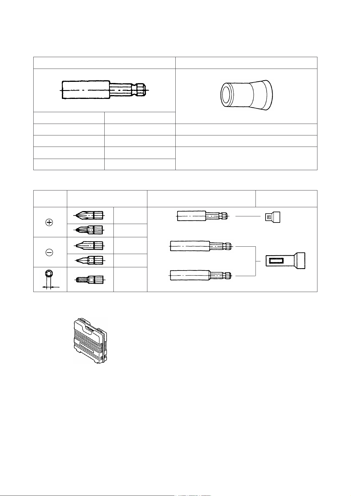
5-2. Optional Accessories
(1) For hex-head screws
Sub-stopper (B)Hex-socket
Magnetic type
H = 6.35 mm
H = 7.94 mm H = 7.94 mm
H = 9.53 mm
H = 10 mm H = 10 mm
(2) For other screws
Screw
head
B
Non magnetic type
H = 6.35 mm
H = 9.53 mm
Bit type Bit holder
No.1
No.2
No.3
No.1
No.2
No.1
No.2
No.3
No.1
No.2
B size
4 mm
5 mm
Magnetic bit holder
(Short type)
Magnetic bit holder
Non-magnetic bit holder
H 1/4
H 5/16
H 3/8
Sub-stopper
Sub-stopper (G)
Sub-stopper (F)
(3) Plastic case
Optional accessories are subject to change without notice.
--- 7 ---
Page 11
6. COMPARISONS WITH SIMILAR PRODUCTS
6-1. W 6VM
Maker
Model
Capacity
Power
input
Drywall screw
Self-drilling screw
U.S.A., Canada
Other areas
No-load rotation
No-load noise level *
Overall
length
Cord
length
Weight *
with long bit holder
with short bit holder
U.S.A., Canada, Europe,
Russia and Oceania
Asia, Africa and other areas
2
mm
mm
W
W
/min
1
dB (A)
mm
mm
m
m
kg
HITACHI
W 6VM
6 (1/4")
6 (1/4")
620
0 --- 6,000
76
328 (12-7/8")
294 (11-19/32")
7.5 (24.6 ft.)
2.5 (8.2 ft.)
1.4 (3.1 lbs.)
710 (115 V, 6.5 A)
U.S.A.: 2.5 (8.2 ft.)
Europe: 4.2 (13.8
*1: Rotation direction is R.
*2: Weight excludes cord and means actual weight.
6-2. W 6V4
Maker
Model
Capacity
Power
input
Drywall screw
Self-drilling screw
U.S.A., Canada
Other areas
No-load rotation
No-load noise level *
Overall
length
Cord
length
Weight *
with long bit holder
with short bit holder
U.S.A., Canada, Europe,
Russia and Oceania
Asia, Africa and other areas
2
mm
mm
W
750 (120 V, 6.6 A)
W
/min
1
dB (A)
mm
mm
m
m
kg
0 --- 4,500
328 (12-7/8")
294 (11-19/32")
7.5 (24.6 ft.)
2.5 (8.2 ft.)
1.4 (3.1 lbs.) 1.3 (2.9 lbs.) 1.4 (3.2 lbs.)
HITACHI
W 6V4
6 (1/4")
6 (1/4")
680 (115 V, 6.4 A)
620
76
268 (10-19/32")
*1: Rotation direction is R.
*2: Weight excludes cord and means actual weight.
*3: U.S.A. only. Europe, Russia and Oceania are 2.5 m.
CP
5 (3/16")
6 (1/4")
570
0 --- 6,000
79
302 (11-7/8")
4 (5/32")
---
680 (120 V, 6.0 A)750 (120 V, 6.6 A)
540
0 --- 5,300
82
310 (12-13/64")
U.S.A.: 2.5 (8.2 ft.)
ft.)
Europe: 4.2 (13.8
1.4 (3.2 lbs.) 1.4 (3.2 lbs.)
W 6V3
6 (1/4")
6 (1/4")
600
0 --- 4,000
79
302 (11-7/8")
7.5 (24.6 ft.)
2.5 (8.2 ft.)
3
*
C
5 (3/16")
6 (1/4")
710 (115 V, 6.5 A)
570
0 --- 4.500
79
302 (11-7/8")
U.S.A.: 2.5 (8.2 ft.)
Europe: 4.2 (13.8 ft.)
ft.)
BP
6 (1/4")
---
500
0 --- 4,000
78
4 (5/32")
---
720 (120 V, 6.3 A)550 (120 V, 4.8 A)
---
0 --- 4,000
82
310 (12-13/64") 312 (12-9/32")
2.5 (8.2 ft.)
2.5 (8.2 ft.)
1.5 (3.3 lbs.) 1.4 (3.2 lbs.)
6-3. W 6VA4
Maker
Model
Capacity
Power
input
Drywall screw
Self-drilling screw
U.S.A., Canada
Other areas
No-load rotation
No-load noise level *
Overall
length
Cord
length
Weight *
with long bit holder
with short bit holder
U.S.A., Canada, Europe,
Russia and Oceania
Asia, Africa and other areas
2
mm
mm
W
W
/min
1
dB (A)
mm
mm
m
m
kg
W 6VA4
6 (1/4")
6 (1/4")
750 (120 V, 6.6 A)
620
0 --- 3,000
76
328 (12-7/8")
294 (11-19/32")
7.5 (24.6 ft.)
2.5 (8.2 ft.)
1.4 (3.1 lbs.) 1.3 (2.9 lbs.) 1.5 (3.3 lbs.)
*1: Rotation direction is R.
*2: Weight excludes cord and means actual weight.
HITACHI
W 6VA3
680 (115 V, 6.5 A)
0 --- 2,600
302 (11-7/8")
268 (10-19/32")
2.5 (8.2 ft.)
--- 8 ---
6 (1/4")
6 (1/4")
600
79
C
5 (3/16")
6 (1/4")
710 (115 V, 6.5 A)
570
0 --- 2,500
79
302 (11-7/8")
U.S.A.: 2.5 (8.2 ft.)
Europe: 4.2 m (13.8
BE
6 (1/4")
---
740 (120 V, 6.5 A)550 (120 V, 4.8 A)
500
0 --- 2,500
0 --- 2,500
78
320 (12-19/32")
2.5 (8.2 ft.)
ft.)
335 (13-13/64")
3.0 (9.8 ft.)
1.6 (3.5 lbs.) 1.4 (3.2 lbs.)
---
---
---
80
Page 12

7. PRECAUTIONS IN SALES PROMOTION
In the interest of promoting the safest and most efficient use of the Models W 6VM, W 6V4 and W 6VA4 electric
screwdrivers by all of our customers, it is very important that at the time of sales the salesperson carefully ensures
that the buyer seriously recognizes the importance of the contents of the Handling Instructions, and fully
understands the meaning of the precautions listed on the Caution Plate attached to each tool.
7-1. Handling Instructions
Although every effort is made in each step of design, manufacture and inspection to provide protection against
safety hazards, the dangers inherent in the use of any electric power tool cannot be completely eliminated.
Accordingly, general precautions and suggestions for the use of electric power tools, and specific precautions and
suggestions for the use of the electric screwdriver are listed in the Handling Instructions to enhance the safe and
efficient use of the tool by the customer. Salespersons must be thoroughly familiar with the contents of the
Handling Instructions to be able to offer appropriate guidance to the customer during sales promotion.
7-2. Caution Plates
The following basic safety precautions are listed on the Name Plate attached to the main body of each tool.
However, these precautions are not listed for European countries.
For Asia and Oceania
CAUTION
Read thoroughly HANDLING INSTRUCTIONS before use.
For the U.S.A. and Canada
WARNING
To reduce the risk of injury, user must read and
understand instruction manual
AVERTISSEMENT
Afin de reduire le risque de blessures, l'utilisateur doit
lire et bien comprendre le mode d'emloi.
7-3. Screw Driving-depth Adjustment
Information and suggestions for screw driving-depth selection for applicable screws are described in the Handling
Instructions. The salesperson must be thoroughly familiar with screw driving-depth adjustment procedures to be
able to instruct the customer/user in performing adjustment so that the screw neither protrudes above nor sinks
excessively below the surface of the workpiece into which the screw is driven.
--- 9 ---
Page 13

Specific adjustment procedures are as follows.
(1) Head of screw protrudes above workpiece surface (Fig. 1).
If dimension A in Fig. 3 is excessively small, the head of the driven screw will protrude above the surface of the
workpiece material as shown in Fig. 1. To adjust dimension A, rotate the locator clockwise as viewed from the
screw mounting end (see Note below). Repeat adjustment as necessary until the head of the driven screw is
properly aligned with the surface of the workpiece.
Material into which
screw is driven
B
Screw
Fig. 1 Fig. 2 Fig. 3
(2) Head of screw sinks below workpiece (Fig. 2).
If dimension A in Fig. 3 is excessively large, the head of the driven screw will sink below the surface of the
workpiece as shown in Fig. 2. To perform adjustment, follow the procedures described in item (1) above, but
rotate the locator counter-clockwise.
Should Hex. and Teks screws be driven when dimension A is excessively large, both the screws and bits may
be easily damaged. Instruct customers/users to perform adjustment correctly without fail.
(NOTE) By turning the locator clockwise or counter-clockwise, dimension A in Fig. 3 can be adjusted
within a maximum dimension of 1.5 mm (0.059"). One complete rotation of the locator is
Material into which
screw is driven
Screw
Screw
Sub-stopper
Locator
Gear cover
divided into twelve settings, each setting permitting an adjustment of 0.125 mm (0.005").
Accordingly, if dimension B in Fig. 1 is 0.25 mm (0.010"), rotate the locator by two settings.
7-4. Self-drilling Screws
Self-drilling screws are most suitable for joining wooden and metal materials, mounting metallic components onto
iron sheets, or installing roofing materials. Self-drilling and self-tapping, they are commonly employed in the
construction industry because:
Separate drilling and tapping processes are not required when securing wooden materials to metal materials.
Consequently, job costs and processes can be drastically reduced.
7-5. Drywall Screws
Drywall screws are most suitable for interior decorating and construction utilizing such materials as gypsum board
and plastic board. Their main features are:
Like Hex. and Teks screws, drywall screws are self-drilling, and can reduce work time.
Wall panels can be mounted cleanly without cracks or chips.
Drywall screws display far stronger holding power than conventional screws when applied to materials
composed of powder or particles, such as gypsum board.
--- 10 ---
Page 14

7-6. Variable-speed Switch
This switch is equipped with a variable speed control circuit. Through the control circuit, the speed can be
controlled up to 65 % of maximum speed according to the degree at which the switch is depressed.
A disadvantage of this system is that if the bit becomes locked resulting in stoppage of the motor, the speed
control circuit may be burnt out. In such a case, the switch should be released immediately or turned OFF. To
avoid damage to the switch circuit, the customer should be advised to increase driving speed gradually until the
screw is driven approximately halfway into the workpiece, then depress the trigger to obtain optimum speed.
100 %
65 %
Speed
0
Trigger stroke
Fig. 4
Switch characteristics (Approximately shown converted into the linear line)
Maximum speed change point
--- 11 ---
Page 15

8. PRECAUTIONS IN DISASSEMBLY AND REASSEMBLY
The numbers in the descriptions below correspond to the item numbers in the Parts List and exploded assembly
diagram. The [BOLD] numbers are for the Model W 6VM, the <Bold> numbers for the Models W 6V4 and
W 6VA4.
8-1. Disassembly
A. Disassembly of the parts within the handle
(1) Removal of the Handle Cover [46] <45>
Loosen the three Tapping Screws (W/Flange) D4 x 20 (Black) [47] <46>, and remove the Handle Cover
[46] <45>.
(2) Removal of the Carbon Brush (Auto Stop Type) (1 Pair) [30] <29>
With a small flat-blade screwdriver, lift up on the spring, and pull the Carbon Brush (Auto Stop Type)
(1 Pair) [30] <29> out from Brush Holder (A) [29] <28> slightly. Next, pull out the terminal portion of
Carbon Brush (Auto Stop Type) (1 Pair) [30] <29> from the Brush Holder (A) [29] <28>. Remove the
carbon brushes from both sides in the same manner.
(3) Removal of the Cord [38] <37>
After loosening the two speed control switch retaining screws, loosen the two Tapping Screws (W/Flange)
D4 x 16 [40] <39> which retain the Cord Clip [39] <38>, and remove the Cord [38] <37> together with the
Cord Armor D8.8 [37] <36>.
B. Removal of the armature and stator
(1) Removal of the Armature [21] <20>
Remove the three Tapping Screws D4 x 25 (Black) [7] <7> from the Gear Cover (A) Ass'y [8] <8>, and
remove the Inner Cover Ass'y [20] <19> with the Armature [21] <20> from the housing. And as illustrated
in Fig. 5, the Inner Cover Ass'y [20] <19> can be removed from the Armature [21] <20> by utilizing a J-130
sleeve (special repair tool, Code No. 970908) and a J-131 plate (special repair tool, Code No. 970909).
(2) Removal of the Stator [24] <23>
First, remove the Fan Guide [22] <21> from the inside of the housing.
Then, loosen the two Hex. Hd. Tapping Screws D4 x 50 [23] <22>, and lightly tap the end surface of the
Housing [36] <35> with a wooden hammer to loosen and remove the Stator [24] <23>.
Fig. 5
--- 12 ---
Page 16

C. Removal of socket (A) ass'y and gear ass'y
(1) Remove Gear Cover (A) Ass'y [8] <8> and the Inner Cover Ass'y [20] <19>, then Socket (A) Ass'y [11]
<11>, Gear Set [14] <14> and Clutch Disc [12] <12> can be removed. If the Gear Set [14] <14> is hard to
remove, lightly tap the end surface of the Inner Cover Ass'y [20] <19> with a wood hammer. Be careful not
to lose the Spring [13] <13> on the outer circumference of the Gear Set [14] <14> and Washer (A) [16]
<16>. As shown in Fig. 5, insert two flat-blade screwdrivers between the Inner Cover Ass'y [20] <19> and
the Gear Set [14] <14> at each side and remove the Gear Set [14] <14> and Ball Bearing 608VVC2PS2L
[15] <15 > from the Inner Cover Ass'y [20] <19> as a single unit.
Inner Cover Ass'y [20] <19>
Gear Set
[14] <14>
Flat-blade screwdriver
Fig. 6
8-2. Reassembly
Reassembly can be accomplished by following the disassembly procedures in reverse. However, special
attention should be given to the following items.
(1) Fan side Ball Bearing [18] <15> for the Armature [21] <20> in the Inner Cover Ass'y [20] <19> should be
renewed in disassembling the Armature [21] <20>.
(2) Lubrication
Grease: Hitachi Motor Grease (Code No. 930035)
Application:
(a) Fill a moderate amount of grease in Gear Cover (A) Ass'y [8] <8>. (If Gear Cover (A) Ass'y [8] <8> is new,
fill it with 7 g of grease.)
(b) Outer circumference and clutch of Socket (A) Ass'y [11] <11>
Flat-blade screwdriver
(c) Teeth and clutch of the Gear Set [14] <14>
(d) Outer circumference of the Gear Set [14] <14>
(e) Clutch and inner circumference of the Clutch Disc [12] <12>
(f) Pinion of the Armature [21] <20>
--- 13 ---
Page 17

(3) Tightening torque
Handle cover retaining screws
Cord clip retaining screws
Gear cover retaining screws
Stator retaining screws
••••••••••••••••••••••••••••••••••••••••••••••••
Speed control switch retaining screws
Inner cover truss screws
•••••••••••••••••••••••••••••••••••••••••••••••
••••••••••••••••••••••••••••••••••••••
•••••••••••••••••••••••••••••••••••••••••••••
•••••••••••••••••••••••••••••••••••••••••
•••••••••••••••••••••••••••
1.5 --- 2.5 N•m {15 --- 25 kg•cm (13.0 --- 21.7 in-Ibs)}
1.5 --- 2.5 N•m {15 --- 25 kg•cm (13.0 --- 21.7 in-Ibs)}
1.5 --- 2.5 N•m {15 --- 25 kg•cm (13.0 --- 21.7 in-Ibs)}
1.5 --- 2.5 N•m {15 --- 25 kg•cm (13.0 --- 21.7 in-Ibs)}
0.4 --- 0.8 N•m {4 --- 8 kg•cm (3.5 --- 6.9 in-Ibs)}
1.4 --- 2.2 N•m {14 --- 22 kg•cm (12.0 --- 18.9 in-Ibs)}
--- 14 ---
Page 18

8-3. Wiring Diagrams
(1) Products with noise suppressor
Fig. 7
(2) Products without noise suppressor
Fig. 8
--- 15 ---
Page 19

8-4. Internal Wire Arrangement and Wiring Work
A. Internal wire arrangement
(1) Products with noise suppressor
(2) Products without noise suppressor
Fig. 9 Schematic diagram
--- 16 ---
Page 20

B. Additional wiring work
General internal wiring can be accomplished by referring to paragraph 8-3 and 8-4-A. The following are special
instructions for switch connection.
(1) Wiring of reversing switch
Insert the lead wire (brown) coming from the
brush holder into the terminal (1) of the reversing
switch, and the lead wire (blue) into the terminal
(2) as shown in Fig. 10. Insert the lead wire
(gray) coming from the stator into the terminal (3)
and the lead wire (red) into the terminal (4). After
insertion, pull each lead wire slightly to check that
the lead wires do not come off. To disconnect the
lead wires, insert a small flat-blade screwdriver
into the slots near the terminals and pull out the
lead wires.
Fig. 10 Wiring of reversing switch
(2) Wiring of variable speed control switch
Insert each cord into the terminal 1 and
terminal 2 of the speed control switch as
shown in Fig. 11, and tighten the screw
[tightening torque: 0.6
_+
5.2
1.7 in-lbs.)]. Insert the lead wire (yellow)
_+
0.2 N•m (6
_+
2 kgf•cm,
coming from the stator into the terminal M1 and
the lead wire (white) into the terminal M2. Insert
each lead wire (white) coming from the noise
suppressor into the terminal C1 and C2. After
insertion, pull each lead wire slightly to check
the lead wires do not come off. To disconnect
the lead wires, insert a small flat-blade
screwdriver into the slots near the terminals and
pull out the lead wires.
Fig. 11 Wiring of speed control switch
8-5. Insulation Tests
On completion of reassembly after repair, measure the insulation resistance and conduct the dielectric strength
test.
Insulation resistance: 7 M Ω or more with DC 500 V Megohm Tester
Dielectric strength: AC 4,000 V/1 minute, with no abnormalities
AC 2,500 V/1 minute, with no abnormalities
••••••••
220 V --- 240 V (
••••••••
110 V --- 127 V (except for U.K. products)
and 110 V for U.K. products
--- 17 ---
)
Page 21

8-6. No-load Current Values
After no-load operation for 30 minutes, the no-load current value should be as follows.
Voltage (V) 110
Current (A) max.
2.5
115 120 220 230 240
2.5 2.5 1.2 1.2 1.1
--- 18 ---
Page 22

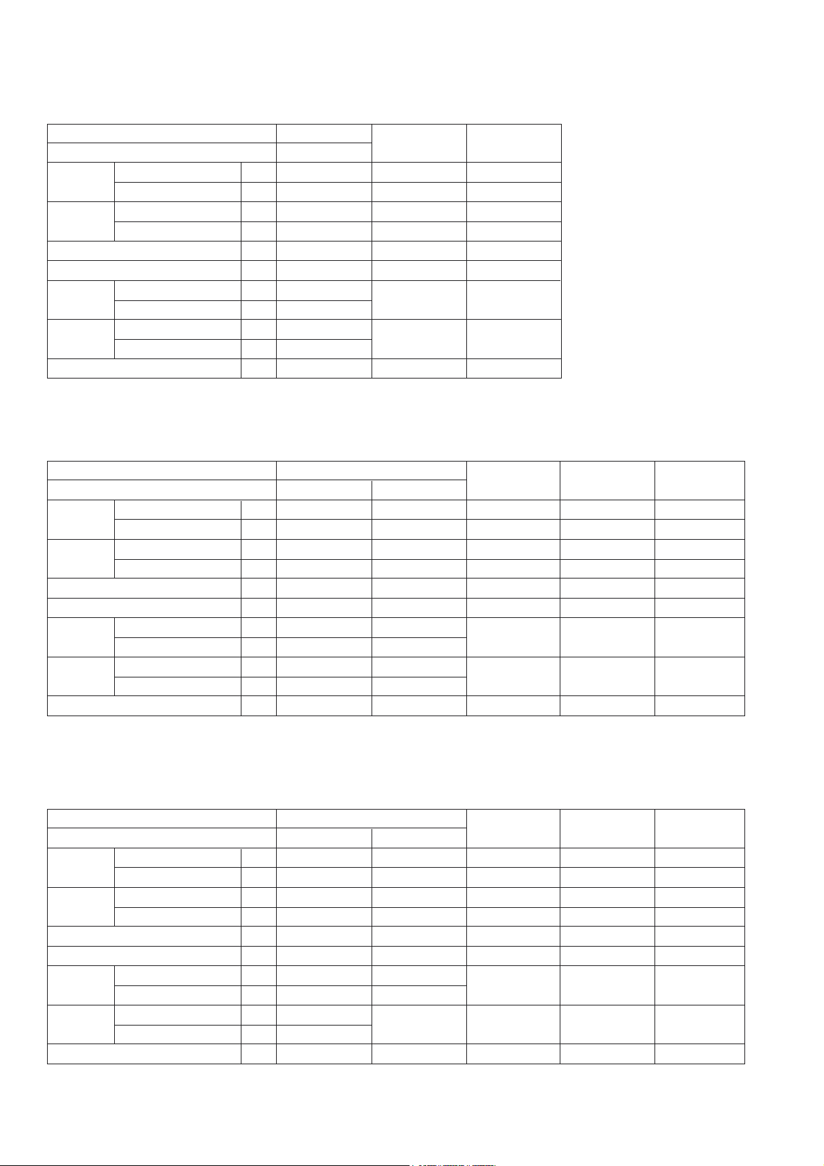
9. STANDARD REPAIR TIME (UNIT) SCHEDULES
MODEL 10 20 30 40 50 60 min.
Fixed
Variable
Work Flow
W 6V4
W 6VA4
W 6VM
Switch
Cord
Cord Armor
Housing
Stator
General Assembly
Armature
Ball Bearing
(608VV)
Washer (A)
Inner Cover
Ass'y
Ball Bearing
(608VV)
Ball Bearing
(6900VV)
[W 6VM]
Fringer (A)
O-Ring (F)
Protect Cover
Clutch Disc
Spring
Gear
Gear Cover
Socket (A)
Set Ring
(A)
Steel Ball x 2
(A) Ass'y
Ass'y
--- 19 ---
Page 23

Hitachi Power Tools
ELECTRIC TOOL PARTS LIST
LIST NO. 0798
SCREW DRIVER
Model W 6VM
1
15
16
17
18
19
2
3
20
2004 • 8 •25
(E1)
501
502
4
5
6
7
21
22
23
503
8
11
9
10
12
504
505
13
14
36
28
29
30
26
27
37
28
29
30
31
39
32
33
40
34
41
24
25
35
46
47
45
44
38
4342
Page 24

PARTS
ITEM
NO.
CODE NO.
DESCRIPTION REMARKS
1 876-031 O-RING (S-16) 1
2 323-487 LOCATOR ASS’Y 1 INCLUD.3
3 323-488 CLICK SPRING 1
4 971-468 FRINGER (A) 1
5 317-662 O-RING (F) 1
6 323-558 PROTECT COVER (A) 1
7 321-057 TAPPING SCREW D4X25 (BLACK) 3
8 323-486 GEAR COVER (A) ASS’Y 1 INCLUD. 5
9 872-573 SET RING 1
10 959-148 STEEL BALL D3.175 (10 PCS.) 2
*11 323-491 SOCKET (A) ASS’Y 1 INCLUD. 9, 10
*11 323-482 SOCKET (A) ASS’Y 1
12 323-476 CLUTCH DISC 1
13 306-024 SPRING 1
14 323-504 GEAR SET 1
15 608-VVM BALL BEARING 608VVC2PS2L 1
16 933-545 WASHER (A) 2
17 323-556
SLOTTED HD. SCREW (SEAL LOCK) M4X8
18 690-0VV BALL BEARING 6900VV2MPS2L 1
19 323-557 FELT (A) 1
20 323-503 INNER COVER ASS’Y (B) 1 INCLUD. 15-19
*21 360-676 ARMATURE (C) 110V 1
*21 360-677U ARMATURE ASS’Y (C) 120V 1 INCLUD. 18, 25
*21 360-677E ARMATURE (C) 220V-230V 1
*21 360-677F ARMATURE (C) 240V 1
22 323-472 FAN GUIDE 1
23 961-672 HEX. HD. TAPPING SCREW D4X50 2
*24 340-599C STATOR 110V-120V 1
*24 340-599E STATOR 220V-240V 1
25 608-VVM BALL BEARING 608VVC2PS2L 1
26 NAME PLATE 1
27 323-471 HOOK 1
28 HITACHI LABEL 2
29 323-512 BRUSH HOLDER (A) 2
30 999-091
CARBON BRUSH (AUTO STOP TYPE) (1 PAIR) 2
*31 323-489 INTERNAL WIRE (BROWN) 1 FOR USA, CAN, KUW, HKG, THA
*32 323-480
CHOKE COIL (W/INTERNAL WIRE) BROWN
33 323-479 SWITCH (1P PILLAR TYPE) W/LOCK 1
*34 323-490 INTERNAL WIRE (BLUE) 1 FOR USA, CAN, KUW, HKG, THA
*35 323-481 CHOKE COIL (W/INTERNAL WIRE) BLUE 1
36 323-483 HOUSING 1
37 953-327 CORD ARMOR D8.8 1
*38 323-559 CORD (LENGTH 7.5M) 1 (CORD ARMOR D8.8)
*38 500-423Z CORD 1 (CORD ARMOR D8.8) FOR KUW
*38 323-560 CORD (LENGTH 7.5M) 1 (CORD ARMOR D8.8) FOR GBR (230V)
*38 323-562 CORD (LENGTH 7.5M) 1 (CORD ARMOR D8.8) FOR GBR (110V)
*38 500-435Z CORD 1 (CORD ARMOR D8.8) FOR HKG
*38 320-130 CORD (LENGTH 7.5M) 1 (CORD ARMOR D8.8) FOR USA, CAN
*38 323-561 CORD (LENGTH 7.5M) 1 (CORD ARMOR D8.8) FOR AUS
*38 500-468Z CORD 1 (CORD ARMOR D8.8) FOR THA
*38 500-470Z CORD 1 (CORD ARMOR D8.8) FOR TPE
ALTERNATIVE PARTS--- 2 ---
*
NO.
USED
INCLUD. 9, 10 FOR HKG, THA, TPE, KOR
2
1
EXCEPT FOR USA, CAN, KUW, HKG, THA
EXCEPT FOR USA, CAN, KUW, HKG, THA
W 6VM
8 -- 04
Page 25

PARTS
ITEM
NO.
CODE NO.
DESCRIPTION
*38 500-409Z CORD 1 (CORD ARMOR D8.8) FOR KOR
39 937-631 CORD CLIP 1
40 984-750 TAPPING SCREW (W/FLANGE) D4X16 2
*41 959-140 CONNECTOR 50091 (10 PCS.) 2
*42 930-039 NOISE SUPPRESSOR 1
*43 994-273 NOISE SUPPRESSOR 1
*44 317-667 INTERNAL WIRE 2
*45 992-635 EARTH TERMINAL 1
46 323-484 HANDLE COVER 1
47 301-653
TAPPING SCREW (W/FLANGE) D4X20 (BLACK) 3
NO.
USED
REMARKS
EXCEPT FOR USA, CAN, KUW, HKG, THA
EXCEPT FOR USA, CAN, KUW, HKG, THA
EXCEPT FOR USA, CAN, KUW, HKG, THA
EXCEPT FOR USA, CAN, KUW, HKG, THA
EXCEPT FOR USA, CAN, KUW, HKG, THA
W 6VM
8 -- 04
ALTERNATIVE PARTS --- 3 ---
*
Page 26

STANDARD ACCESSORIES
ITEM
NO.
CODE NO.
DESCRIPTION
* 501 323-352 SUB STOPPER (G) 1
502 971-511Z + DRIVER BIT (A) NO.2 25L 1
* 503 317-674 MAGNETIC BIT HOLDER ASS’Y (41L) 1 INCLUD. 502
* 503 323-353 MAGNETIC BIT HOLDER ASS’Y (81.1L) 1 INCLUD. 502 FOR HKG
* 503 982-554Z MAGNETIC BIT HOLDER (75L) 1 FOR HOL, AUS
* 503 323-354 MAGNETIC BIT HOLDER ASS’Y (47.1L) 1 INCLUD. 502 FOR THA,KOR
* 504 323-351 SUB STOPPER (F) 1 FOR USA, CAN, AUS, HOL, HKG
* 505 310-904 CASE 1 FOR ESP
NO.
USED
REMARKS
EXCEPT FOR USA, CAN, AUS, HOL, HKG
OPTIONAL ACCESSORIES
ITEM
CODE NO.
NO.
601 317-670
602 317-671
DESCRIPTION
SUB STOPPER (B) FOR H3/8, H10 HEX. SOCKET
SUB STOPPER (B) FOR H5/16 HEX. SOCKET
603 317-827 SUB STOPPER (B) H1/4 HEX. SOCKET 1
* 604 985-330 MAGNETIC HEX. SOCKET 3/8”X65L 1 EXCEPT FOR THA, HKG, TPE, KOR
* 605 985-321 MAGNETIC HEX. SOCKET 10MMX65L 1 EXCEPT FOR THA, HKG, TPE, KOR
* 606 985-322 MAGNETIC HEX. SOCKET 5/16”X65L 1 EXCEPT FOR THA, HKG, TPE, KOR
* 607 985-332 MAGNETIC HEX. SOCKET 1/4”X65L 1 EXCEPT FOR THA, HKG, TPE, KOR
* 608 985-326 NON-MAGNETIC HEX. SOCKET 3/8” 65L 1 EXCEPT FOR THA, HKG, TPE, KOR
* 609 985-329 NON-MAGNETIC HEX. SOCKET 10MM 65L 1 EXCEPT FOR THA, HKG, TPE, KOR
* 610 985-327 NON-MAGNETIC HEX. SOCKET 5/16” 65L 1 EXCEPT FOR THA, HKG, TPE, KOR
*611 985-328 NON-MAGNETIC HEX. SOCKET 1/4” 65L 1 EXCEPT FOR THA, HKG, TPE, KOR
* 612 982-563Z NON-MAGNETIC BIT HOLDER 1 EXCEPT FOR THA, HKG, TPE, KOR
* 613 323-356 MAGNETIC HEX. SOCKET 5/16”X71.1L 1 EXCEPT FOR THA, HKG, TPE, KOR
* 614 323-355 MAGNETIC HEX. SOCKET 10MMX71.1L 1 EXCEPT FOR THA, HKG, TPE, KOR
615 985-333 + DRIVER BIT NO. 1 25L 1
616 971-512Z + DRIVER BIT (A) NO. 3 25L 1
617 985-334 + DRIVER BIT NO. 1 25L W/STEPPED ROD 1
618 985-335 + DRIVER BIT NO. 2 25L W/STEPPED ROD 1
619 985-336 - DRIVER BIT 4MMX25 1
620 985-337 - DRIVER BIT 5MMX25 1
621 985-338 - DRIVER BIT 6MMX25 1
622 985-339 - DRIVER BIT 8MMX25 1
623 985-340 - DRIVER BIT 4MMX25 (W/STEPPED ROD) 1
624 985-341 - DRIVER BIT 5MMX25 (W/STEPPED ROD) 1
625 985-342 HEX. BIT 4MMX25L 1
626 985-343 HEX. BIT 5MMX25L 1
627 985-344 HEX. BIT 6MMX25L 1
628 310-904 CASE 1
NO.
USED
1
1
REMARKS
W 6VM
--- 4 --- 8 -- 04
ALTERNATIVE PARTS
*
Printed in Japan
(040825N)
Page 27

Hitachi Power Tools
ELECTRIC TOOL PARTS LIST
LIST NO. E701
SCREW DRIVER
Model W 6V4
1
15
16
17
15
18
19
2
2004 • 8 •30
(E1)
501
3
4
5
6
7
20
21
22
502
503
8
11
9
10
12
13
504
505
14
35
27
28
29
25
26
36
27
28
29
30
38
31
32
39
33
40
23
24
34
45
46
44
43
37
4241
Page 28

PARTS
ITEM
NO.
CODE NO.
DESCRIPTION REMARKS
1 876-031 O-RING (S-16) 1
2 323-487 LOCATOR ASS’Y 1 INCLUD. 3
3 323-488 CLICK SPRING 1
4 971-468 FRINGER (A) 1
5 317-662 O-RING (F) 1
6 323-558 PROTECT COVER (A) 1
7 321-057 TAPPING SCREW D4X25 (BLACK) 3
8 323-486 GEAR COVER (A) ASS’Y 1 INCLUD. 5
9 872-573 SET RING 1
10 959-148 STEEL BALL D3.175 (10 PCS.) 2
*11 323-491 SOCKET (A) ASS’Y 1 INCLUD. 9, 10
*11 323-482 SOCKET (A) ASS’Y 1
12 323-476 CLUTCH DISC 1
13 306-024 SPRING 1
14 323-485 GEAR SET 1
15 608-VVM BALL BEARING 608VVC2PS2L 2
16 933-545 WASHER (A) 1
17 323-556
SLOTTED HD. SCREW (SEAL LOCK) M4X8
18 323-557 FELT (A) 1
19 323-473 INNER COVER ASS’Y (A) 1 INCLUD. 15-18
*20 360-672 ARMATURE (A) 110V 1
*20 360-673U ARMATURE ASS’Y (A) 120V 1 INCLUD. 15, 24
*20 360-673E ARMATURE (A) 220V-230V 1
*20 360-673F ARMATURE (A) 240V 1
21 323-472 FAN GUIDE 1
22 961-672 HEX. HD. TAPPING SCREW D4X50 2
*23 340-599C STATOR 110V-120V 1
*23 340-599E STATOR 220V-240V 1
24 608-VVM BALL BEARING 608VVC2PS2L 1
25 NAME PLATE 1
26 323-471 HOOK 1
27 HITACHI LABEL 2
28 323-512 BRUSH HOLDER (A) 2
29 999-091
CARBON BRUSH (AUTO STOP TYPE) (1 PAIR)
*30 323-489 INTERNAL WIRE (BROWN) 1 FOR THA, HKG, KUW, USA, CAN
*31 323-480
CHOKE COIL (W/INTERNAL WIRE) BROWN
32 323-479 SWITCH (1P PILLAR TYPE) W/LOCK 1
*33 323-490 INTERNAL WIRE (BLUE) 1 FOR THA, HKG, KUW, USA, CAN
*34 323-481 CHOKE COIL (W/INTERNAL WIRE) BLUE 1
35 323-483 HOUSING 1
36 953-327 CORD ARMOR D8.8 1
*37 323-559 CORD (LENGTH 7.5M) 1 (CORD ARMOR D8.8)
*37 500-468Z CORD 1 (CORD ARMOR D8.8) FOR THA
*37 500-423Z CORD 1 (CORD ARMOR D8.8) FOR KUW
*37 320-130 CORD (LENGTH 7.5M) 1 (CORD ARMOR D8.8) FOR USA, CAN
*37 500-435Z CORD 1 (CORD ARMOR D8.8) FOR HKG
*37 500-409Z CORD 1 (CORD ARMOR D8.8) FOR KOR
*37 500-470Z CORD 1 (CORD ARMOR D8.8) FOR TPE
*37 323-561 CORD (LENGTH 7.5M) 1 (CORD ARMOR D8.8) FOR AUS
*37 323-562 CORD (LENGTH 7.5M) 1 (CORD ARMOR D8.8) FOR GBR (110V)
*37 323-560 CORD (LENGTH 7.5M) 1 (CORD ARMOR D8.8) FOR GBR (230V)
ALTERNATIVE PARTS--- 2 ---
*
NO.
USED
INCLUD. 9, 10 FOR TPE, THA, HKG, KOR
2
2
1
EXCEPT FOR THA, HKG, KUW, USA, CAN
EXCEPT FOR THA, HKG, KUW, USA, CAN
W 6V4
8 -- 04
Page 29

PARTS
ITEM
NO.
CODE NO.
DESCRIPTION
38 937-631 CORD CLIP 1
39 984-750 TAPPING SCREW (W/FLANGE) D4X16 2
*40 959-140 CONNECTOR 50091 (10 PCS.) 2
*41 930-039 NOISE SUPPRESSOR 1
*42 994-273 NOISE SUPPRESSOR 1
*43 317-667 INTERNAL WIRE 2
*44 992-635 EARTH TERMINAL 1
45 323-484 HANDLE COVER 1
46 301-653
TAPPING SCREW (W/FLANGE) D4X20 (BLACK) 3
NO.
USED
W 6V4
REMARKS
EXCEPT FOR THA, HKG, KUW, USA, CAN
EXCEPT FOR THA, HKG, KUW, USA, CAN
EXCEPT FOR THA, HKG, KUW, USA, CAN
EXCEPT FOR THA, HKG, KUW, USA, CAN
EXCEPT FOR THA, HKG, KUW, USA, CAN
8 -- 04
ALTERNATIVE PARTS --- 3 ---
*
Page 30

STANDARD ACCESSORIES
ITEM
NO.
CODE NO.
DESCRIPTION
* 501 323-352 SUB STOPPER (G) 1
502 971-511Z + DRIVER BIT (A) NO. 2 25L 1
* 503 317-674 MAGNETIC BIT HOLDER ASS’Y (41L) 1 INCLUD. 502
* 503 323-354 MAGNETIC BIT HOLDER ASS’Y (47.1L) 1 INCLUD. 502 FOR TPE, THA, KOR
* 503 982-554Z MAGNETIC BIT HOLDER (75L) 1 FOR AUS, HOL, USA, CAN
* 503 323-353 MAGNETIC BIT HOLDER ASS’Y (81.1L) 1 INCLUD. 502 FOR HKG
* 504 323-351 SUB STOPPER (F) 1 FOR HKG, AUS, HOL, USA, CAN
* 505 310-904 CASE 1 FOR ESP
NO.
USED
REMARKS
EXCEPT FOR HKG, AUS, HOL, USA, CAN
OPTIONAL ACCESSORIES
ITEM
CODE NO.
NO.
601 317-670
602 317-671
DESCRIPTION
SUB STOPPER (B) FOR H3/8, H10 HEX. SOCKET
SUB STOPPER (B) FOR H5/16 HEX. SOCKET
603 317-827 SUB STOPPER (B) H1/4 HEX. SOCKET 1
* 604 985-330 MAGNETIC HEX. SOCKET 3/8”X65L 1 EXCEPT FOR TPE, THA, HKG, KOR
* 605 985-321 MAGNETIC HEX. SOCKET 10MMX65L 1 EXCEPT FOR TPE, THA, HKG, KOR
* 606 985-322 MAGNETIC HEX. SOCKET 5/16”X65L 1 EXCEPT FOR TPE, THA, HKG, KOR
* 607 985-332 MAGNETIC HEX. SOCKET 1/4”X65L 1 EXCEPT FOR TPE, THA, HKG, KOR
* 608 985-326 NON-MAGNETIC HEX. SOCKET 3/8” 65L 1 EXCEPT FOR TPE, THA, HKG, KOR
* 609 985-329 NON-MAGNETIC HEX. SOCKET 10MM 65L 1 EXCEPT FOR TPE, THA, HKG, KOR
* 610 985-327 NON-MAGNETIC HEX. SOCKET 5/16” 65L 1 EXCEPT FOR TPE, THA, HKG, KOR
*611 985-328 NON-MAGNETIC HEX. SOCKET 1/4” 65L 1 EXCEPT FOR TPE, THA, HKG, KOR
* 612 982-563Z NON-MAGNETIC BIT HOLDER 1 EXCEPT FOR TPE, THA, HKG, KOR
* 613 323-355 MAGNETIC HEX. SOCKET 10MMX71.1L 1 FOR TPE, THA, HKG, KOR
* 614 323-356 MAGNETIC HEX. SOCKET 5/16”X71.1L 1 FOR TPE, THA, HKG, KOR
615 985-333 + DRIVER BIT NO. 1 25L 1
616 971-512Z + DRIVER BIT (A) NO. 3 25L 1
617 985-334 + DRIVER BIT NO. 1 25L W/STEPPED ROD 1
618 985-335 + DRIVER BIT NO. 2 25L W/STEPPED ROD 1
619 985-336 - DRIVER BIT 4MMX25 1
620 985-337 - DRIVER BIT 5MMX25 1
621 985-338 - DRIVER BIT 6MMX25 1
622 985-339 - DRIVER BIT 8MMX25 1
623 985-340 - DRIVER BIT 4MMX25 (W/STEPPED ROD) 1
624 985-341 - DRIVER BIT 5MMX25 (W/STEPPED ROD) 1
625 985-342 HEX. BIT 4MMX25L 1
626 985-343 HEX. BIT 5MMX25L 1
627 985-344 HEX. BIT 6MMX25L 1
628 310-904 CASE 1
NO.
USED
1
1
REMARKS
W 6V4
--- 4 --- 8 -- 04
ALTERNATIVE PARTS
*
Printed in Japan
(040830N)
Page 31

Hitachi Power Tools
ELECTRIC TOOL PARTS LIST
LIST NO. E702
SCREW DRIVER
Model W 6VA4
1
15
16
17
15
18
2
3
19
2004 • 8 •30
(E1)
501
502
4
5
6
7
20
21
22
503
504
8
11
9
10
12
13
505
506
507
14
35
27
28
29
25
26
36
27
28
29
30
38
31
32
39
33
40
23
24
34
45
46
44
43
37
4241
Page 32

PARTS
ITEM
NO.
CODE NO.
DESCRIPTION REMARKS
1 876-031 O-RING (S-16) 1
2 323-487 LOCATOR ASS’Y 1 INCLUD. 3
3 323-488 CLICK SPRING 1
4 971-468 FRINGER (A) 1
5 317-662 O-RING (F) 1
6 323-558 PROTECT COVER (A) 1
7 321-057 TAPPING SCREW D4X25 (BLACK) 3
8 323-486 GEAR COVER (A) ASS’Y 1 INCLUD. 5
9 872-573 SET RING 1
10 959-148 STEEL BALL D3.175 (10 PCS.) 2
*11 323-491 SOCKET (A) ASS’Y 1 INCLUD. 9, 10
*11 323-482 SOCKET (A) ASS’Y 1 INCLUD. 9, 10 FOR TPE, SIN, HKG
12 323-476 CLUTCH DISC 1
13 306-024 SPRING 1
14 323-474 GEAR SET 1
15 608-VVM BALL BEARING 608VVC2PS2L 2
16 933-545 WASHER (A) 1
17 323-556
SLOTTED HD. SCREW (SEAL LOCK) M4X8
18 323-557 FELT (A) 1
19 323-473 INNER COVER ASS’Y (A) 1 INCLUD. 15-18
*20 360-670 ARMATURE (B) 100V-110V 1
*20 360-671U ARMATURE ASS’Y (B) 120V 1 INCLUD. 15, 24
*20 360-671E ARMATURE (B) 220V-230V 1
*20 360-671F ARMATURE (B) 240V 1
21 323-472 FAN GUIDE 1
22 961-672 HEX. HD. TAPPING SCREW D4X50 2
*23 340-599C STATOR 110V-120V 1
*23 340-599E STATOR 220V-240V 1
24 608-VVM BALL BEARING 608VVC2PS2L 1
25 NAME PLATE 1
26 323-471 HOOK 1
27 HITACHI LABEL 2
28 323-512 BRUSH HOLDER (A) 2
29 999-091
CARBON BRUSH (AUTO STOP TYPE) (1 PAIR) 2
*30 323-489 INTERNAL WIRE (BROWN) 1 FOR SAU, SIN, HKG, USA, CAN, IND
*31 323-480
CHOKE COIL (W/INTERNAL WIRE) BROWN
32 323-479 SWITCH (1P PILLAR TYPE) W/LOCK 1
*33 323-490 INTERNAL WIRE (BLUE) 1 FOR SAU, SIN, HKG, USA, CAN, IND
*34 323-481 CHOKE COIL (W/INTERNAL WIRE) BLUE 1 EXCEPT FOR SAU, SIN, HKG, USA, CAN, IND
35 323-483 HOUSING 1
36 953-327 CORD ARMOR D8.8 1
*37 323-559 CORD (LENGTH 7.5M) 1 (CORD ARMOR D8.8)
*37 500-409Z CORD 1 (CORD ARMOR D8.8) FOR SAU, IND
*37 500-423Z CORD 1 (CORD ARMOR D8.8) FOR SIN
*37 323-561 CORD (LENGTH 7.5M) 1 (CORD ARMOR D8.8) FOR NZL, AUS
*37 500-247Z CORD 1 (CORD ARMOR D8.8) FOR SAF, YEN
*37 320-130 CORD (LENGTH 7.5M) 1 (CORD ARMOR D8.8) FOR USA, CAN
*37 500-435Z CORD 1 (CORD ARMOR D8.8) FOR HKG
*37 500-470Z CORD 1 (CORD ARMOR D8.8) FOR TPE
*37 323-562 CORD (LENGTH 7.5M) 1 (CORD ARMOR D8.8) FOR GBR (110V)
*37 323-560 CORD (LENGTH 7.5M) 1 (CORD ARMOR D8.8) FOR GBR (230V)
ALTERNATIVE PARTS--- 2 ---
*
NO.
USED
2
1 EXCEPT FOR SAU, SIN, HKG, USA, CAN, IND
W 6VA4
8 -- 04
Page 33

PARTS
ITEM
NO.
CODE NO.
DESCRIPTION
*37 323-563 CORD (LENGTH 7.5M) 1 (CORD ARMOR D8.8) FOR SUI
38 937-631 CORD CLIP 1
39 984-750 TAPPING SCREW (W/FLANGE) D4X16 2
*40 959-140 CONNECTOR 50091 (10 PCS.) 2
*41 930-039 NOISE SUPPRESSOR 1 EXCEPT FOR SAU, SIN, HKG, USA, CAN, IND
*42 994-273 NOISE SUPPRESSOR 1 EXCEPT FOR SAU, SIN, HKG, USA, CAN, IND
*43 317-667 INTERNAL WIRE 2 EXCEPT FOR SAU, SIN, HKG, USA, CAN, IND
*44 992-635 EARTH TERMINAL 1 EXCEPT FOR SAU, SIN, HKG, USA, CAN, IND
45 323-484 HANDLE COVER 1
46 301-653
TAPPING SCREW (W/FLANGE) D4X20 (BLACK) 3
NO.
USED
EXCEPT FOR SAU, SIN, HKG, USA, CAN, IND
REMARKS
W 6VA4
8 -- 04
ALTERNATIVE PARTS --- 3 ---
*
Page 34

STANDARD ACCESSORIES
ITEM
NO.
CODE NO.
DESCRIPTION
* 501 323-352 SUB STOPPER (G) 1
* 502 971-511Z + DRIVER BIT (A) NO. 2 25L 1 EXCEPT FOR TPE
* 503 317-674 MAGNETIC BIT HOLDER ASS’Y (41L) 1
* 503 982-554Z MAGNETIC BIT HOLDER (75L) 1 FOR NZL, AUS, USA, CAN
* 503 323-354 MAGNETIC BIT HOLDER ASS’Y (47.1L) 1 INCLUD. 502 FOR SIN
* 503 323-353 MAGNETIC BIT HOLDER ASS’Y (81.1L) 1 INCLUD. 502 FOR HKG
* 504 323-356 MAGNETIC HEX. SOCKET 5/16”X71.1L 1 FOR TPE
* 505 317-671
SUB STOPPER (B) FOR H5/16 HEX. SOCKET
* 506 323-351 SUB STOPPER (F) 1 FOR HKG, NZL, AUS, USA, CAN
* 507 310-904 CASE 1 FOR ESP
NO.
USED
EXCEPT FOR HKG, NZL, AUS, USA, CAN, TPE
REMARKS
INCLUD. 502 EXCEPT FOR TPE, SIN, HKG,
NZL, AUS, USA, CAN
1 FOR TPE
OPTIONAL ACCESSORIES
ITEM
CODE NO.
NO.
601 317-670
602 317-671
DESCRIPTION
SUB STOPPER (B) FOR H3/8, H10 HEX. SOCKET
SUB STOPPER (B) FOR H5/16 HEX. SOCKET
603 317-827 SUB STOPPER (B) H1/4 HEX. SOCKET 1
* 604 985-330 MAGNETIC HEX. SOCKET 3/8”X65L 1 EXCEPT FOR TPE, SIN, HKG
* 605 985-321 MAGNETIC HEX. SOCKET 10MMX65L 1 EXCEPT FOR TPE, SIN, HKG
* 606 985-322 MAGNETIC HEX. SOCKET 5/16”X65L 1 EXCEPT FOR TPE, SIN, HKG
* 607 985-332 MAGNETIC HEX. SOCKET 1/4”X65L 1 EXCEPT FOR TPE, SIN, HKG
* 608 985-326 NON-MAGNETIC HEX. SOCKET 3/8” 65L 1 EXCEPT FOR TPE, SIN, HKG
* 609 985-329 NON-MAGNETIC HEX. SOCKET 10MM 65L 1 EXCEPT FOR TPE, SIN, HKG
* 610 985-327 NON-MAGNETIC HEX. SOCKET 5/16” 65L 1 EXCEPT FOR TPE, SIN, HKG
*611 985-328 NON-MAGNETIC HEX. SOCKET 1/4” 65L 1 EXCEPT FOR TPE, SIN, HKG
* 612 982-563Z NON-MAGNETIC BIT HOLDER 1 EXCEPT FOR TPE, SIN, HKG
* 613 323-355 MAGNETIC HEX. SOCKET 10MMX71.1L 1 FOR TPE, SIN, HKG
* 614 323-356 MAGNETIC HEX. SOCKET 5/16”X71.1L 1 FOR SIN, HKG
615 985-333 + DRIVER BIT NO. 1 25L 1
616 971-512Z + DRIVER BIT (A) NO. 3 25L 1
617 985-334 + DRIVER BIT NO. 1 25L W/STEPPED ROD 1
618 985-335 + DRIVER BIT NO. 2 25L W/STEPPED ROD 1
619 985-336 - DRIVER BIT 4MMX25 1
620 985-337 - DRIVER BIT 5MMX25 1
621 985-338 - DRIVER BIT 6MMX25 1
622 985-339 - DRIVER BIT 8MMX25 1
623 985-340 - DRIVER BIT 4MMX25 (W/STEPPED ROD) 1
624 985-341 - DRIVER BIT 5MMX25 (W/STEPPED ROD) 1
625 985-342 HEX. BIT 4MMX25L 1
626 985-343 HEX. BIT 5MMX25L 1
627 985-344 HEX. BIT 6MMX25L 1
628 310-904 CASE 1
NO.
USED
1
1
REMARKS
W 6VA4
--- 4 --- 8 -- 04
ALTERNATIVE PARTS
*
Printed in Japan
(040830N)
Page 35

 Loading...