

Page 1
SCREW DRIVER
MODEL
W 6VB2
W 8VB
POWER TOOLS
TECHNICAL DATA
AND
W 6VB2, W 8VB
SERVICE MANUAL
W
LIST Nos. W 6VB2: 0780
W 8VB: 0781
SPECIFICATIONS AND PARTS ARE SUBJECT TO CHANGE FOR IMPROVEMENT
Jul. 1999
Page 2
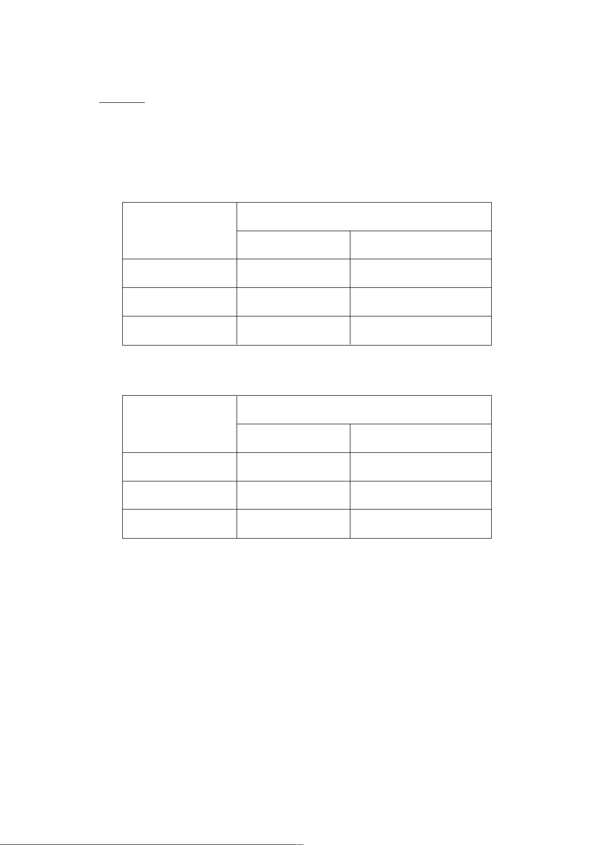
REMARK:
Throughout this TECHNICAL DATA AND SERVICE MANUAL, a symbol(s)
is(are) used in the place of company name(s) and model name(s) of our
competitor(s). The symbol(s) utilized here is(are) as follows:
Model: W 6VB2
Competitors
Symbols Utilized
Company Name
Model Name
Model: W 8VB
Symbol Utilized
C
B BOSCH
P
P
MAKITA
DeWALT
Company Name
DeWALT
6802BV
GSR6-20TE
(1423VSR)
DW266
Competitor
Model Name
DW265
Page 3

CONTENTS
[ Business Section ]
1. PRODUCT NAME
2. MARKETING OBJECTIVE
3. APPLICA TIONS
4. SELLING POINTS
5. SPECIFICATIONS
5-1. Specifications
5-2. Optional Accessories
••••••••••••••••••••••••••••••••••••••••••••••••••••••••••••••••••••••••••••••••••••••••••••••••••••••••••••••••••••••••
••••••••••••••••••••••••••••••••••••••••••••••••••••••••••••••••••••••••••••••••••••••••••••••••••••••••••
•••••••••••••••••••••••••••••••••••••••••••••••••••••••••••••••••••••••••••••••••••••••••••••••••••••••••••••••••••••••••••
•••••••••••••••••••••••••••••••••••••••••••••••••••••••••••••••••••••••••••••••••••••••••••••••••••••••••••••••••••••••
•••••••••••••••••••••••••••••••••••••••••••••••••••••••••••••••••••••••••••••••••••••••••••••••••••••••••••••••••••••••
•••••••••••••••••••••••••••••••••••••••••••••••••••••••••••••••••••••••••••••••••••••••••••••••••••••••••••••••••••••••
•••••••••••••••••••••••••••••••••••••••••••••••••••••••••••••••••••••••••••••••••••••••••••••••••••••••••••••
6. COMPARISONS WITH SIMILAR PRODUCTS
6-1. W 6VB2
6-2. W 8VB
6-3. Screw tightening time
7. PRECAUTIONS IN SALES PROMOTION
7-1. Handling Instructions
7-2. Caution Plates
7-3. Screw Driving-Depth Adjustment
7-4. Self-Drilling Screws
7-5. Dry-Wall Screws
7-6. Variable-Speed Switch
•••••••••••••••••••••••••••••••••••••••••••••••••••••••••••••••••••••••••••••••••••••••••••••••••••••••••••••••••••••••••••••••••
•••••••••••••••••••••••••••••••••••••••••••••••••••••••••••••••••••••••••••••••••••••••••••••••••••••••••••••••••••••••••••••••••••
••••••••••••••••••••••••••••••••••••••••••••••••••••••••••••••••••••••••••••••••••••••••••••••••••••••••••••
•••••••••••••••••••••••••••••••••••••••••••••••••••••••••••••••••••••••••••••••••••
••••••••••••••••••••••••••••••••••••••••••••••••••••••••••••••••••••••••••••••••••••••••••••••••••••••••••••••
•••••••••••••••••••••••••••••••••••••••••••••••••••••••••••••••••••••••••••••••••••••••••••••••••••••••••••••••••••••••
••••••••••••••••••••••••••••••••••••••••••••••••••••••••••••••••••••••••••••••••••••••••••••
••••••••••••••••••••••••••••••••••••••••••••••••••••••••••••••••••••••••••••••••••••••••••••••••••••••••••••••••
•••••••••••••••••••••••••••••••••••••••••••••••••••••••••••••••••••••••••••••••••••••••••••••••••••••••••••••••••••••
••••••••••••••••••••••••••••••••••••••••••••••••••••••••••••••••••••••••••••••••••••••••••••••••••••••••••••
••••••••••••••••••••••••••••••••••••••••••••••••••••••••••••••••••••••••••••
Page
1
1
1
1
2
2
3
4
4
4
5
6
6
6
6
7
7
8
8. PRECAUTIONS IN DISASSEMBLY AND REASSEMBLY
8-1. Disassembly
8-2. Reassembly
8-3. Wiring Diagrams
8-4. Internal Wire Arrangement and Wiring Work
8-5. Insulation Tests
8-6. No-load Current Values
9. STANDARD REPAIR TIME (UNIT) SCHEDULES
•••••••••••••••••••••••••••••••••••••••••••••••••••••••••••••••••••••••••••••••••••••••••••••••••••••••••••••••••••••••••
•••••••••••••••••••••••••••••••••••••••••••••••••••••••••••••••••••••••••••••••••••••••••••••••••••••••••••••••••••••••••
••••••••••••••••••••••••••••••••••••••••••••••••••••••••••••••••••••••••••••••••••••••••••••••••••••••••••••••••••••
•••••••••••••••••••••••••••••••••••••••••••••••••••••••••••••••••••••••••••••
••••••••••••••••••••••••••••••••••••••••••••••••••••••••••••••••••••••••••••••••••••••••••••••••••••••••••••••••••••••
••••••••••••••••••••••••••••••••••••••••••••••••••••••••••••••••••••••••••••••••••••••••••••••••••••••••••
••••••••••••••••••••••••••••••••••••••••••••••••••••••••••••••••••••••••
[ Appendix ]
Assembly Diagram for W 6VB2
Assembly Diagram for W 8VB
•••••••••••••••••••••••••••••••••••••••••••••••••••••••••••••••••••••••••••••••••••••••••••••••••••••
•••••••••••••••••••••••••••••••••••••••••••••••••••••••••••••••••••••••••••••••••••••••••••••••••••••••
•••••••••••••••••••••••••••••••••••••••••••••••••••••••••••
8
8
9
10
11
13
13
14
15
19
Page 4
1. PRODUCT NAME
Hitachi Screw Driver, Models W 6VB2
W 8VB
2. MARKETING OBJECTIVE
The W 6VB screw driver has been on the market for 14 years. The new W 6VB2/W 8VB are totally redesigned
with an easy-to-grip body structure and other features in response to the diverse needs of customers. In
particular, the W 8VB has been introduced to meet the demand for higher torque. Our market share is expected
to grow with the release of these new models which broaden our lineup of screw drivers.
3. APPLICA TIONS
Hex. and Teks screws: Fastening metal onto metal, or metal onto wood
Exterior construction Installation of siding on buildings
Installation of galvanized iron sheet or corrugated sheet roofing
Plate assembly Assembly and mounting of advertising billboards
Assembly of metal frames for vinyl greenhouses
Assembly and installation of automobile stamped sections
Various other interior/exterior construction and plate assembly jobs
Drywall screws: Fastening metal studs and drywall
Interior construction Installation of ceilings, paneling or partitions in offices,
shops, supermarkets, apartment houses, schools, factories, etc.
Wood screws: Interior construction Assembly and installation of interior wood paneling,
Installation of flooring in gymnasiums and similar buildings
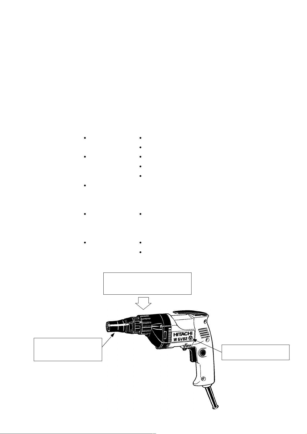
4. SELLING POINTS
Compact and lightweight
Overall length: 285 mm (11-1/4")
Weight: 1.4 kg (3.1 Ibs)
Detachable nosepiece for:
Easy unscrewing
Easy bit changes
High-power motor:
Speedy screw fastening
--- 1 ---
Page 5
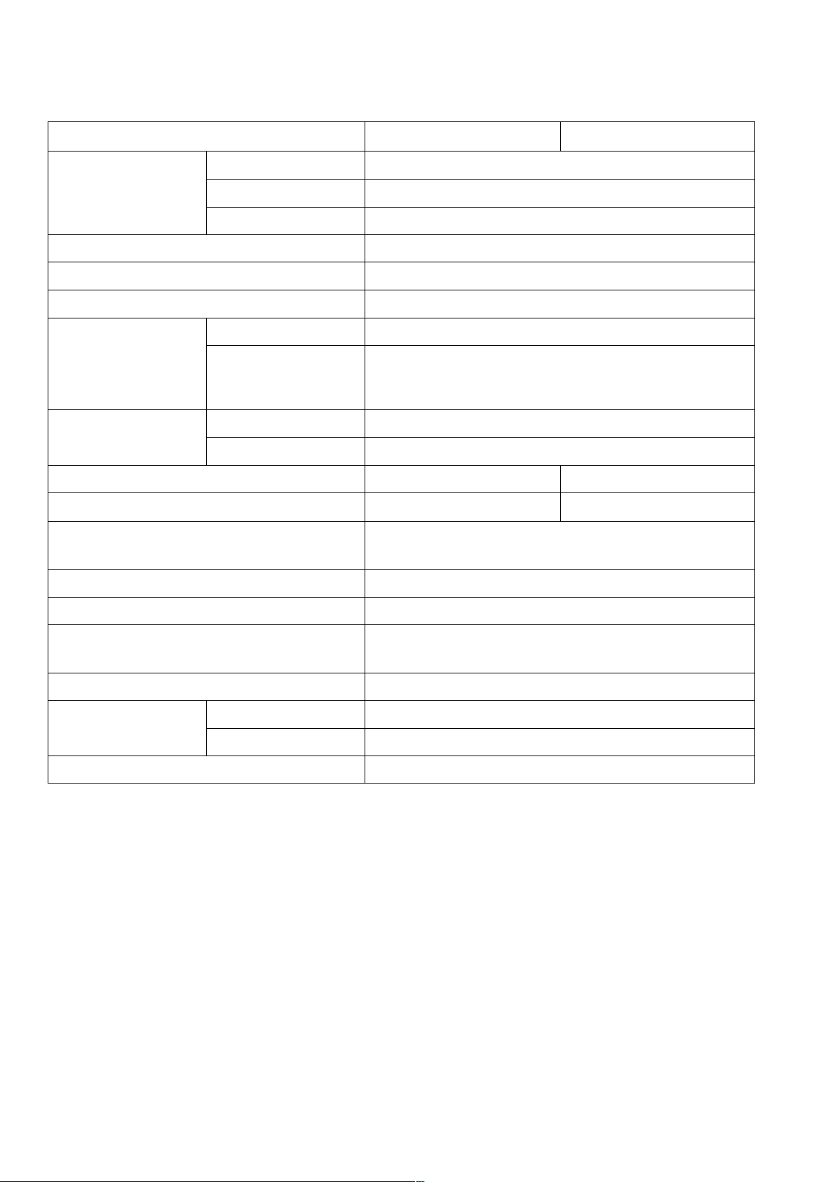
5. SPECIFICATIONS
5-1. Specifications
Model
Capacity
Bit mounting size
Power source
Type of motor
Full-load current
Power input
No-load speed
Full-load speed
Enclosure
Drywall screw
Self-drilling screw
Wood screw
U.S.A., Canada
Other areas
U.S.A., Canada
Other areas
W 6VB2
W 8VB
6 mm (1/4")
6 mm (1/4")
5.8 mm dia. x 50 mm ( 7/32" dia. x 2")
6.35 mm (1/4")
Single phase, AC 50 Hz or 60 Hz
Single phase, AC commutator motor
6.4 A (115 V)
2.9 A (220 V)
5.9 A (110 V) 2.8 A (230 V)
2.7 A (240 V)
640 W
600 W
0 --- 2,600 /min
0 --- 1,700 /min
0 --- 2,000 /min 0 --- 1,200 /min
Housing, Handle cover, Inner cover and Gear cover
••••••••••••••••••••••••••••••••••••••••••••••••••••
Polyamide resin
Switch
Handle
Weight
Packaging
Cord
Standard accessory
Type
Overall length
Variable switch with reversing switch
Pistol grip handle
•••••••••••••••
Net
Gross
•••••••••••
1.4 kg (3.1 Ibs) (without cord)
1.9 kg (4.2 Ibs)
Corrugated cardboard box
Two core cabtire cable
2.5 m (8.2 ft.)
Magnetic hexagon socket
••••••••••••••••••••••••••••••••••••••••
1
--- 2 ---
Page 6
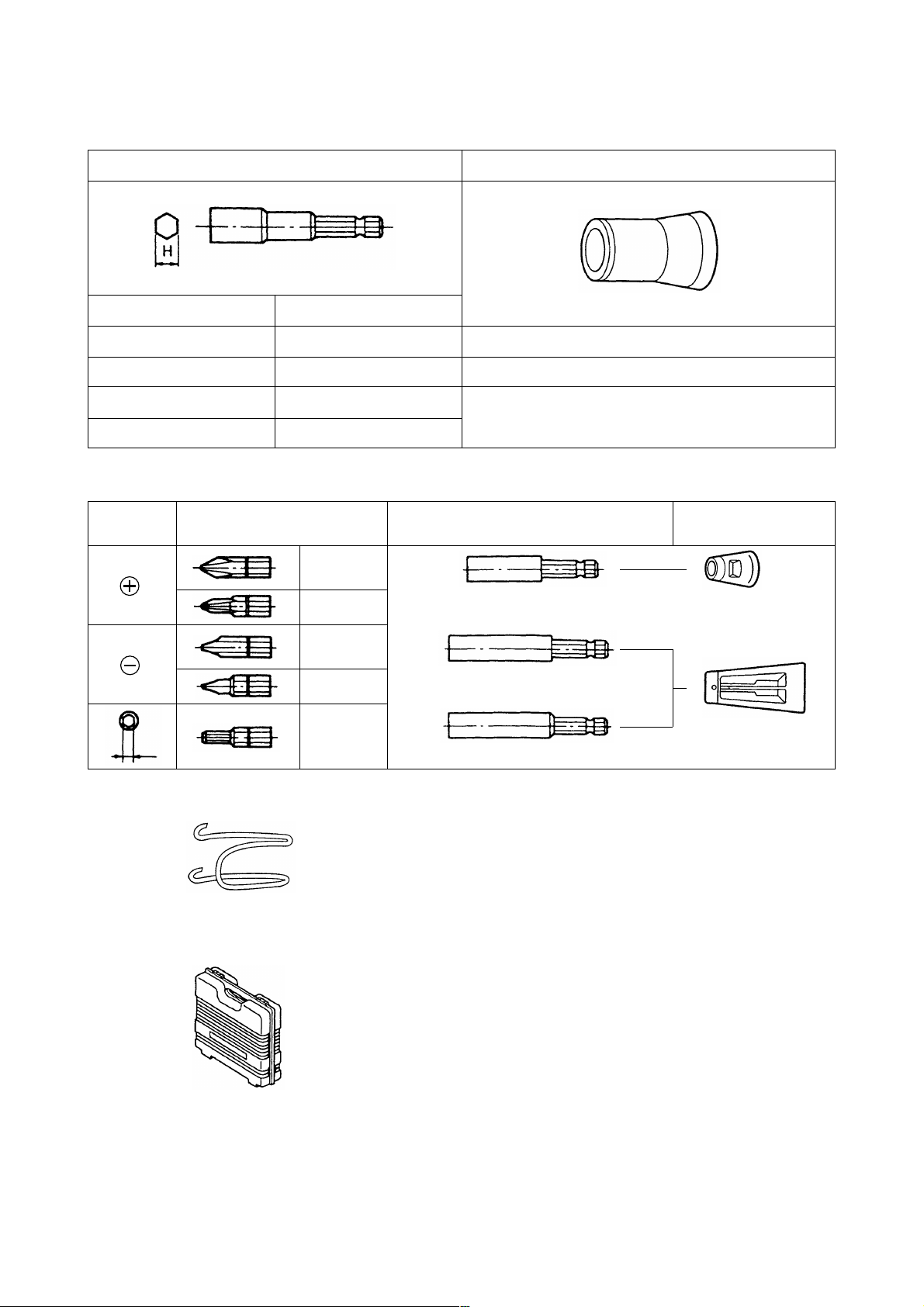
5-2. Optional Accessories
(1) For hex-head screws
Sub-stopper (B)Hex-socket
Magnetic type
H = 6.35 mm
H = 7.94 mm H = 7.94 mm
H = 9.53 mm
H = 10 mm H = 10 mm
(2) For other screws
Screw
head
B
Non magnetic type
H = 6.35 mm
H = 9.53 mm
Bit type Bit holder
No.1
No.2
No.3
No.1
No.2
No.1
No.2
No.3
No.1
No.2
B size
4 mm
5 mm
Magnetic bit holder
(Short type)
Magnetic bit holder
Non-magnetic bit bolder
H 1/4
H 5/16
H 3/8
Sub-stopper
Sub-stopper (A)
Sub-stopper (C)
(3) Hook
(4) Plastic case
Optional accessories are subject to change without notice.
--- 3 ---
Page 7
6. COMPARISONS WITH SIMILAR PRODUCTS
6-1. W 6VB2
Maker
Model
Capacity Self-drilling screw
Dry-wall screw
Wood screw
Power input U.S.A.
Other areas
Voltage, Full-load current
No-load rotation
No-load noise level
Max. output
Overall length
Cord length
Weight
6-2. W 8VB
mm
mm
mm
W
V, A
/min
dB (A)
W
mm
m
kg
HITACHI
W 6VB2 W 6VB
666 66.3
665------
5.8 dia. x 50 5.8 dia. x 50
680
600
115, 6.4
0 --- 2600
79
640
285
2.5
1.4
520
520
115, 5.0
0 --- 2600
81
550
290
2.5 2.5
1.7
CBP
---
---
510 600
115, 4.8 120, 5.5 120, 6.5
80 82 82
485 560 540
265 305 300
1.7 1.9 1.6
---
---
2.5
---
---
---
0 --- 26000 --- 2500 0 --- 2000
2.4
Maker
Model
Capacity
Power input U.S.A.
Voltage, Full-load current
No-load rotation
No-load noise level
Max. output
Overall length
Cord length
Weight
Self-drilling screw
Dry-wall screw
Wood screw
Other Areas
mm
mm
mm
W
V, A
/min
dB (A)
W
mm
m
kg
HITACHI
W 8VB
88
6
6.2 dia. x 50
680
600
115, 6.4
0 --- 1700
79
640
285
2.5
1.4
P
---
---
---
---
120, 6.5
0 --- 2000
83
540
300
2.4
1.6
--- 4 ---
Page 8
6-3. Screw tightening time
Tables 1 and 2 show the relationship between thrust and tightening time based on factory tests. The tightening
time may vary a little as screws are not necessarily uniform. The time information is for reference.
<W 6VB2>
Table 1
Mean tightening time (sec.)
Tightening condition
Teks screw:
5 dia. x 25L (13/64" x 1")
Mild steel plate: T3.2 (1/8")
Teks screw:
5 dia. x 25L (13/64" x 1")
Mild steel plate: T5 (13/64")
Teks screw:
6 dia. x 25L (15/64" x 1")
Mild steel plate: T3.2 (1/8")
Teks screw:
6 dia. x 25L (15/64" x 1")
Mild steel plate: T5 (13/64")
Wood screw
5.8 dia. x 38L (7/32" x 1-1/2")
Wood: Lauan
<W 8VB>
Tightening condition
Teks screw:
5 dia. x 25L (13/64" x 1")
Mild steel plate: T3.2 (1/8")
Teks screw:
5 dia. x 25L (13/64" x 1")
Mild steel plate: T5 (13/64")
Teks screw:
6 dia. x 25L (15/64" x 1")
Mild steel plate: T3.2 (1/8")
Teks screw:
6 dia. x 25L (15/64" x 1")
Mild steel plate: T5 (13/64")
Wood screw:
5.8 dia. x 38L (7/32" x 1-1/2")
Wood: Lauan
Power source HITACHI
W 6VB2 W 6VB
120 V 60 Hz
230 V 50 Hz
120 V 60 Hz
230 V 50 Hz
120 V 60 Hz
230 V 50 Hz
120 V 60 Hz
230 V 50 Hz
120 V 60 Hz
230 V 50 Hz
Table 2
Power source
120 V 60 Hz
230 V 50 Hz
120 V 60 Hz
230 V 50 Hz
120 V 60 Hz
230 V 50 Hz
120 V 60 Hz
230 V 50 Hz
120 V 60 Hz
230 V 50 Hz
2.70 3.00 2.90
3.20 ---
3.60
2.70
3.20
4.00
4.20
0.40
0.60
Mean tightening time (sec.)
HITACHI
W 8VB
3.90
4.00 ---
5.30 4.90
5.30
4.40
4.00
5.50
6.30
0.70
0.70
CBP
---
3.60
3.40
---
2.90
---
3.90
---
0.55 --- 0.75
P
3.80
---
3.90
---
5.40
---
0.60
---
---
--- 3.80
--- 5.70
0.50 0.40
---
3.502.60 ---2.40
---
4.80
---
---
---
4.00
---
3.302.80 ---
---
4.304.00
---
---
--- 5 ---
Page 9

7. PRECAUTIONS IN SALES PROMOTION
In the interest of promoting the safest and most efficient use of the Models W 6VB2 and W 8VB electric
screwdrivers by all of our customers, it is very important that at the time of sales the salesperson carefully ensures
that the buyer seriously recognizes the importance of the contents of the Handling Instructions, and fully
understands the meaning of the precautions listed on the Caution Plate attached to each tool.
7-1. Handling Instructions
Although every effort is made in each step of design, manufacture and inspection to provide protection against
safety hazards, the dangers inherent in the use of any electric power tool cannot be completely eliminated.
Accordingly, general precautions and suggestions for the use of electric power tools, and specific precautions and
suggestions for the use of the electric screwdriver are listed in the Handling Instructions to enhance the safe and
efficient use of the tool by the customer. Salespersons must be thoroughly familiar with the contents of the
Handling Instructions to be able to offer appropriate guidance to the customer during sales promotion.
7-2. Caution Plates
The following basic safety precautions are listed on the Name Plate attached to the main body of each tool.
However, these precautions are not listed for European countries.
For Asia and Oceania
CAUTION
Read thoroughly HANDLING INSTRUCTIONS before use.
For the U.S.A. and Canada
WARNING
To reduce the risk of injury, user must read and
understand instruction manual
AVERTISSEMENT
Afin de reduire le risque de blessures, l'utilisateur doit
lire et bien comprendre le mode d'emloi.
7-3. Screw Driving-Depth Adjustment
Information and suggestions for screw driving-depth selection for applicable screws are described in the Handling
Instructions. The salesperson must be thoroughly familiar with screw driving-depth adjustment procedures to be
able to instruct the customer/user in performing adjustment so that the screw neither protrudes above nor sinks
excessively below the surface of the workpiece into which the screw is driven.
--- 6 ---
Page 10
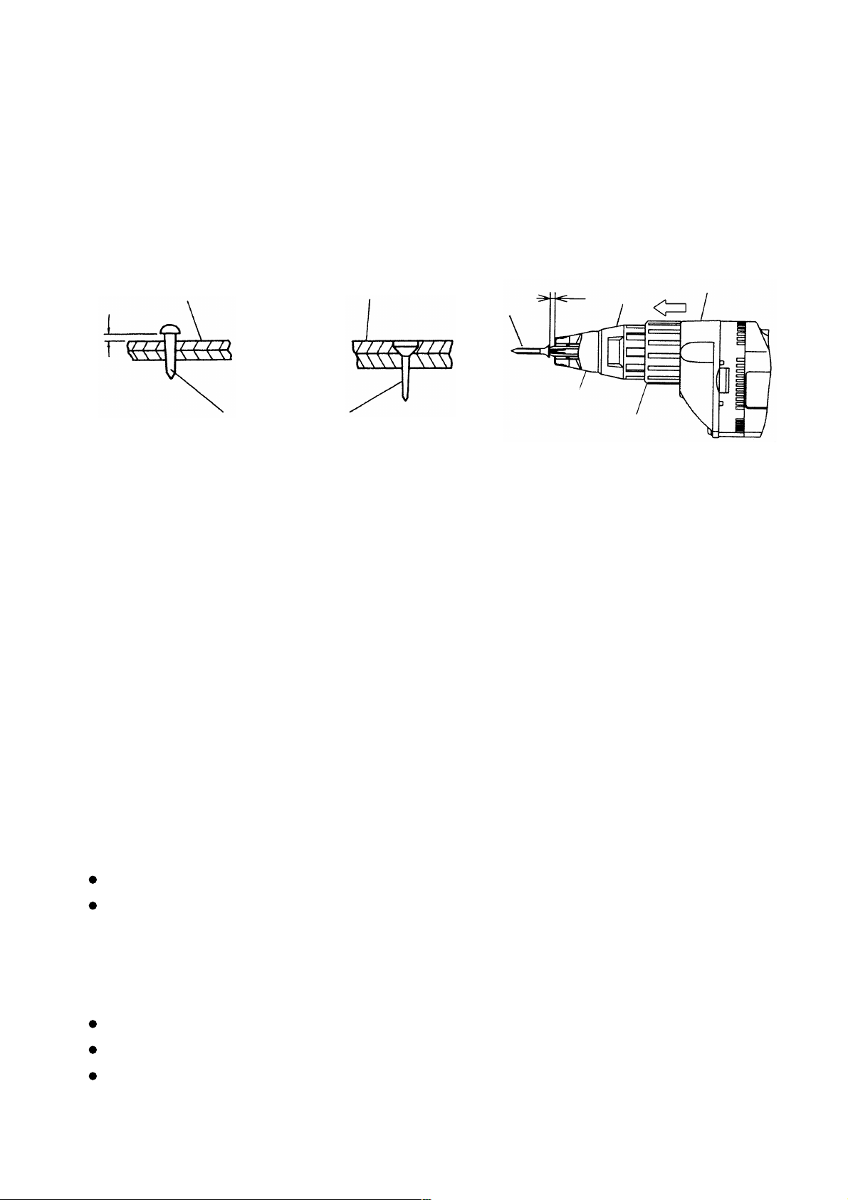
Specific adjustment procedures are as follows
(1) Head of screw protrudes above workpiece surface (Fig. 1)
If dimension A in Fig. 3 is excessively small, the head of the driven screw will protrude above the surface of the
workpiece material as shown in Fig. 1. To adjust dimension A, pull the lock sleeve in the direction indicated by
the arrow in Fig. 3 to disengage the lock sleeve from the gear cover spline, and rotate the lock sleeve
clockwise as viewed from the screw mounting end (see Note below). Repeat adjustment as necessary until
the head of the driven screw is properly aligned with the surface of the workpiece.
Material into which screw
is driven
B
Screw
Fig. 1 Fig. 2 Fig. 3
(2) Head of screw sinks below workpiece (Fig. 2)
If dimension A in Fig. 3 is excessively large, the head of the driven screw will sink below the surface of the
workpiece as shown in Fig. 2. To perform adjustment, follow the procedures described in item (1) above, but
rotate the lock sleeve counter-clockwise.
Should Hex and Teks screws be driven when dimension A is excessively large, both the screws and bits may
be easily damaged. Instruct customers/users to perform adjustment correctly without fail.
(NOTE) By turning the lock sleeve clockwise or counter-clockwise, dimension A in Fig. 3 can be adjusted
within a maximum dimension of 1.5 mm (0.059"). One complete rotation of the lock sleeve is
Material into which screw
is driven
Screw
Screw
A
Sub-stopper
Gear cover
Locator
Lock sleeve
divided into ten settings, each setting permitting an adjustment of 0.15 mm (0.006"). Accordingly,
if dimension B in Fig. 1 is 0.3 mm (0.012"), rotate the lock sleeve by two settings.
7-4. Self-Drilling Screws
Self-drilling screws are most suitable for joining wooden and metal materials, mounting metallic components onto
iron sheets, or installing roofing materials. Self-drilling and self-tapping, they are commonly employed in the
construction industry because:
Separate drilling and tapping processes are not required when securing wooden materials to metal materials.
Consequently, job costs and processes can be drastically reduced.
7-5. Drywall Screws
Drywall screws are most suitable for interior decorating and construction utilizing such materials as gypsum board
and plastic board. Their main features are:
Like Hex and Teks screws, drywall screws are self-drilling, and can reduce work time.
Wall panels can be mounted cleanly without cracks or chips.
Drywall screws display far stronger holding power than conventional screws when applied to materials
composed of powder or particles, such as gypsum board.
--- 7 ---
Page 11

7-6. Variable-Speed Switch
This switch is equipped with a variable speed control circuit. Through the control circuit, the speed can be
controlled up to 75 % of maximum speed according to the degree at which the switch is depressed.
A disadvantage of this system is that if the bit becomes locked resulting in stoppage of the motor, the speed
control circuit may be burnt out. In such a case, the switch should be released immediately or turned OFF. To
avoid damage to the switch circuit, the customer should be advised to increase driving speed gradually until the
screw is driven approximately halfway into the workpiece, then depress the trigger to obtain optimum speed.
100 %
75 %
speed
0
Trigger stroke
Fig. 4
Switch characteristics (Approximately shown converted into the linear line)
Maximum speed change point
8. PRECAUTIONS IN DISASSEMBLY AND REASSEMBLY
The [BOLD] numbers in the descriptions below correspond to the item numbers in the Parts List and the exploded
assembly diagram.
8-1. Disassembly
A. Disassembly of the parts within the handle
(1) Removal of the Handle Cover
Loosen the three Tapping Screws D4 x 20 [31], and remove the Handle Cover [29].
(2) Removal of the Carbon Brushes
With a small flat-blade screwdriver, lift up on the Brush Holder [36], and pull it out slightly.
Next, pull out the terminal portion which connects the two Carbon Brushes [35] and the lead wires from the
Speed Control Switch [32]. When pulling the terminal, it is best to push the Carbon Brushes fully into the
Brush Holder.
(3) Removal of the Cord
Loosen the two Tapping Screws D4 x 16 [44] which retain the Cord Clip [45], and remove the Cord [48]
together with the Cord Armor [46].
B. Removal of the armature and stator
(1) Removal of the Armature
Remove the three Tapping Screws D4 x 40 [9] from the Gear Cover Ass'y [10], and remove the Inner
Cover Ass'y [23] from the Housing [29]. The Armature [25] can then be taken out.
(2) Removal of the Stator
First, remove the Fan Guide [26] from the inside of the Housing.
Then, loosen the two Tapping Screws D4 x 50 [27], and lightly tap the end surface of the Housing [29] with
a wooden hammer to loosen and remove the Stator [28].
--- 8 ---
Page 12
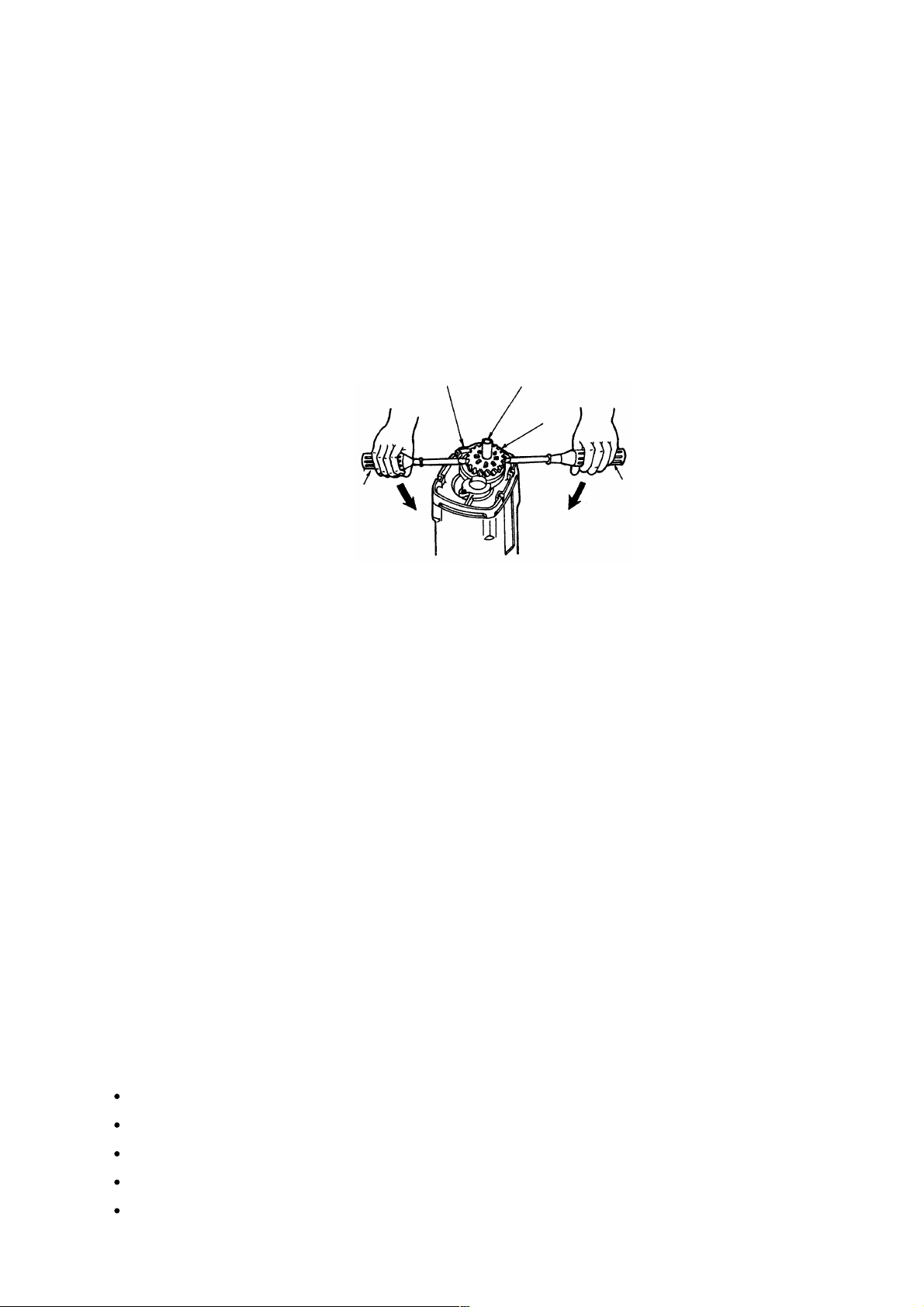
C. Removal of the socket (B) ass'y, gear ass'y and second pinion ass'y
(1) Remove the Gear Cover Ass'y [10] and the Inner Cover Ass'y [23], then the Socket (B) Ass'y [12], Gear
Ass'y [15] and Second Pinion Ass'y [20] can be removed. If the Gear Ass'y [15] is hard to remove, lightly
tap the end surface of the Inner Cover Ass'y [23] with a wood hammer. If the Second Pinion Ass'y [20] is
hard to remove, lightly tap the end surface of the Gear Cover Ass'y [10] with a wood hammer. Be careful
not to lose the Spring [14] on the outer circumference of the Gear Shaft [16] and the Washer [22] on the
outer circumference of the Second Pinion Ass'y [20].
As shown in Fig. 5, insert two flat-blade screwdrivers between the Inner Cover Ass'y [23] and Gear Ass'y
[15] at each side and remove the Gear Ass'y [15], Gear Shaft [16] and Ball Bearing [17] from the Inner
Cover Ass'y as a single unit.
Inner Cover Ass'y [23]
Gear Shaft [16]
Gear
Ass'y [15]
Flat-blade screwdriver
Flat-blade screwdriver
Fig. 5
8-2. Reassembly
Reassembly can be accomplished by following the disassembly procedures in reverse. However, special
attention should be given to the following items.
(1) Lubrication
Grease: Hitachi Motor Grease (Code No. 930035)
Application:
(a) Fill a moderate amount of grease in the Gear Cover Ass'y [10]. (If the Gear Cover Ass'y is new, fill it with
7 g of grease.)
(b) Outer circumference and clutch of the Socket (B) Ass'y [12]
(c) Teeth and clutch of the Gear Ass'y [15]
(d) Outer circumference of the Gear Shaft [16]
(e) Teeth and outer circumference of the Second Pinion Ass'y [20]
(f) Teeth of the First Gear [21]
(g) Pinion of the Armature [25]
(2) Tightening torque
Handle cover retaining screws
Cord clip retaining screws
Gear cover retaining screws
Stator retaining screws
Speed control switch retaining screws
••••••••••••••••••••••••••••••••••••••••••••••••••••••
•••••••••••••••••••••••••••••••••••••••••••••••••••••••••••••
••••••••••••••••••••••••••••••••••••••••••••••••••••••••••
•••••••••••••••••••••••••••••••••••••••••••••••••••••••••••••••••
••••••••••••••••••••••••••••••••••••••••••••
--- 9 ---
15 --- 25 kg•cm (13.0 --- 21.7 Ibs-in)
15 --- 25 kg•cm (13.0 --- 21.7 Ibs-in)
15 --- 25 kg•cm (13.0 --- 21.7 Ibs-in)
15 --- 25 kg•cm (13.0 --- 21.7 Ibs-in)
4 --- 8 kg•cm (3.5 --- 6.9 Ibs-in)
Page 13
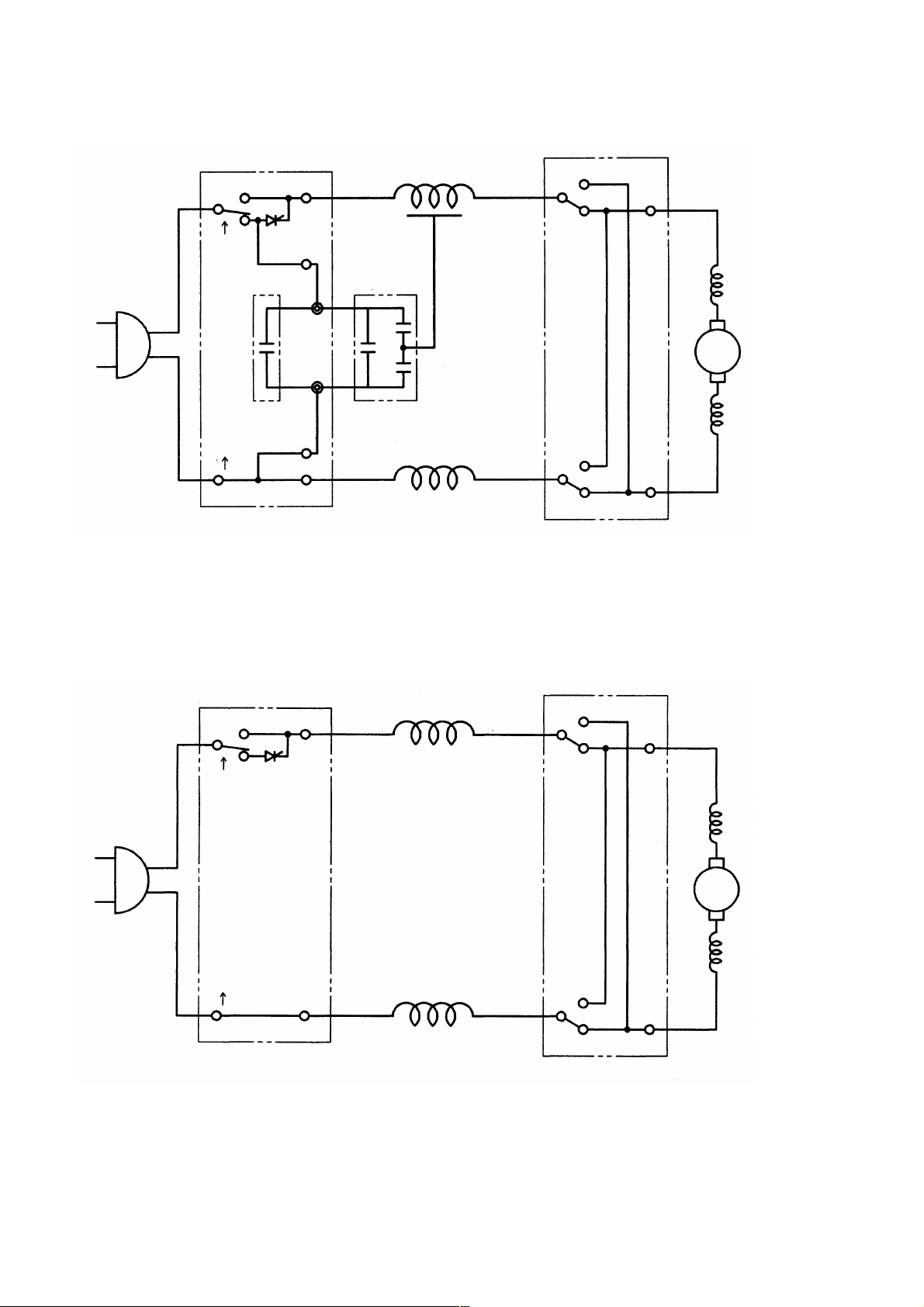
8-3. Wiring Diagrams
(1) Products with noise suppressor
Power source
Variable switch
1
Capacitor
C2
2
M1
C1
M2
White Gray
Noise
suppressor
Stator
Stator
Fig. 6
RedYellow
Reversing switch
2
1
4
3
Blue
Choke coil
Ar
Choke coil
Brown
(2) Products without noise suppressor
V ariable switch
M1
1
Power source
2
M2
White
Yellow
Stator
Stator
Gray
Red
Reversing switch
2
1
4
3
Blue
Choke coil
Ar
Choke coil
Brown
Fig. 7
--- 10 ---
Page 14

8-4. Internal Wire Arrangement and Wiring Work
A. Internal wire arrangement
Insert earth terminal between
stator core and housing
White
(Stator)
Brown
(Carbon brush)
Blue
(Carbon brush)
Yellow
(Stator)
Gray
(Stator)
Blue
(Carbon brush)
White
(Stator)
Noise suppressor
Fig. 8 Schematic diagram
--- 11 ---
Page 15

B. Additional wiring work
General internal wiring can be accomplished by
referring to paragraph 8-3 and 8-4-A. The followings
are special instructions for switch connection.
(1) Wiring of reversing switch
Insert the lead wire (red) coming from the stator
into the terminal (1) of the reversing switch, and
the lead wire (gray) into the terminal (2) as shown
in Fig. 9. Insert the lead wire (brown) coming
from the carbon brush into the terminal (3) and
the lead wire (blue) into the terminal (4). After
insertion, pull each lead wire slightly to check that
the lead wires do not come off. To disconnect the
lead wires, insert a small flat-blade screwdriver
into the slots near the terminals and pull out the
lead wires.
(Stator) (Carbon brush)
Red
Blue
(Carbon brush) (Stator)
Fig. 9 Wiring of reversing switch
Brown
Gray
--- 12 ---
Page 16

(2) Wiring of variable speed control switch
Insert each cord into the terminal 1 ↑ and
terminal 2 ↑ of the speed control switch as shown
in Fig. 10, and tighten the screw [tightening
torque: 0.6 _+ 0.2 N•m (6 _+ 2 kgf•cm, 5.2 _+ 1.7
Ibs-in)]. Insert the lead wire (white) coming from
the stator into the terminal M1 and the lead wire
(yellow) into the terminal M2. Insert each lead
wire (white) coming from the noise suppressor
into the terminal C1 and C2. After insertion, pull
each lead wire slightly to check the lead wires do
not come off. To disconnect the lead wires, insert
a small flat-blade screwdriver into the slots near
the terminals and pull out the lead wires.
(Stator)
(Noise suppressor)
White
Yellow
White
(Noise suppressor)
(Stator)
White
(Cord) (Cord)
Fig. 10 Wiring of speed control switch
8-5. Insulation Tests
On completion of reassembly after repair, measure the insulation resistance and conduct the dielectric strength
test.
Insulation resistance: 7 M Ω or more with DC 500 V Megohm Tester
Dielectric strength: AC 4,000 V/1 minute, with no abnormalities
AC 2,500 V/1 minute, with no abnormalities
••••••••
220 V --- 240 V (
••••••••
110 V --- 127 V (except for U.K. products)
and 110 V for U.K. products
8-6. No-load Current Values
After no-load operation for 30 minutes, the no-load current value should be as follows
Voltage (V) 110
115 120 220 230 240
)
Current (A) max.
2.5
2.5 2.5 1.2 1.2 1.1
--- 13 ---
Page 17

9. STANDARD REPAIR TIME (UNIT) SCHEDULES
MODEL 10 20 30 40 50 60 min.
Fixed
Variable
Work Flow
W 6VB2
W 8VB
Speed control
Cord Armor
Cord
Carbon Brush
General Assembly
switch
Housing.Handle
Cover Set
Stator
x 2
Armature
Ball Bearing
(608VV) x 2
Inner Cover
Ass'y
Spring
Gear Ass'y
Gear Shaft
Ball Bearing
(608VV) x 2
Second Pinion
Ass'y
First Gear
Sub Stopper(B)
Locator (A)
Lock Sleeve (A)
O-Ring (S-28)
Fringer (A)
O-Ring (F)
Gear Cover
Ass'y
Set Ring
Socket (B)
Ass'y
Steel Ball
D3.175
--- 14 ---
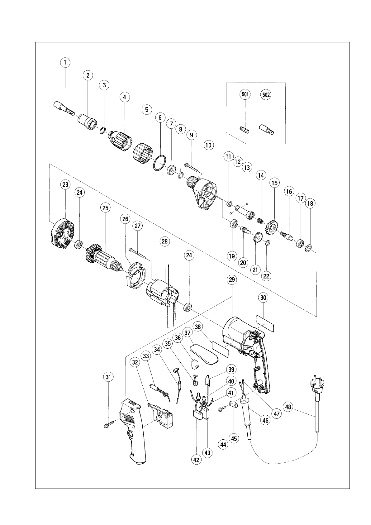
Page 18

Assembly Diagram for W 6VB2
--- 15 ---
Page 19

PARTS
ITEM
CODE NO. DESCRIPTION
NO.
* 1 985-322 MAGNETIC HEX. SOCKET 5/16"X65L 1 FOR AUS,GBR,NOR,USA
* 1 985-321 MAGNETIC HEX. SOCKET 10MMX65L 1 FOR HOL,FIN,CHN
* 2 317-670
* 2 317-671
* 2 317-673
* 2 317-672
* 2 317-899
3 876-031 O-RING (S-16) 1
4 317-666 LOCATOR (A) 1
5 317-665 LOCK SLEEVE (A) 1
6 873-731 O-RING (S-28) 1
7 971-468 FRINGER (A) 1
8 317-662 O-RING (F) 1
9 306-664 TAPPING SCREW (W/FLANGE) D4X40 3
10 317-661 GEAR COVER ASS’Y 1 INCLUD.8,19
11 872-573 SET RING 1
12 317-664 SOCKET (B) ASS’Y 1 INCLUD.11,13
13 959-148 STEEL BALL D3.175 (10 PCS.) 2
14 306-024 SPRING 1
15 317-771 GEAR ASS’Y 1 INCLUD.16
16 307-340 GEAR SHAFT 1
17 608-VVM BALL BEARING 608VVMC2EPS2L 1
18 987-641 WASHER (A) 1
19 608-VVM BALL BEARING 608VVMC2EPS2L 1
20 317-770 SECOND PINION ASS’Y 1 INCLUD.21
21 317-772 FIRST GEAR 1
22 317-663 WASHER 1
23 317-660 INNER COVER ASS’Y 1 INCLUD.17,18
24 608-VVM BALL BEARING 608VVMC2EPS2L 2
* 25 360-492C ARMATURE 110V 1
* 25 360-492U ARMATURE ASS’Y 115V 1 INCLUD.24
* 25 360-492E ARMATURE 220V-230V 1
* 25 360-492F ARMATURE 240V 1
26 305-398 FAN GUIDE (B) 1
27 950-515 TAPPING SCREW D4X50 2
* 28 340-436C STATOR 110V-115V 1
* 28 340-436E STATOR 220V-230V 1
* 28 340-224F STATOR 240V 1
29 317-659 HOUSING.HANDLE COVER SET 1
30 NAME PLATE 1
31 302-086 TAPPING SCREW (W/FLANGE) D4X20 (BLACK) 3
* 32 314-916 SPEED CONTROL SWITCH (2P) 100V-115V 1 FOR GBR (110V),USA
* 32 314-921 SPEED CONTROL SWITCH (2P) 220V-240V 1
* 33 317-668 INTERNAL WIRE (A) 1 FOR AUS,GBR,FRG,FRA,HOL,FIN,AUT,NOR
* 33 314-917 INTERNAL WIRE (B) (BLUE) 1 FOR USA
* 34 317-669 INTERNAL WIRE (B) 1 FOR AUS,GBR,FRG,FRA,HOL,FIN,AUT,NOR
* 34 314-918 INTERNAL WIRE (B) (BROWN) 1 FOR USA
35 999-041 CARBON BRUSH (1 PAIR) 2
36 955-203 BRUSH HOLDER 2
37 317-676 HOOK (A) 1
38 HITACHI LABEL 1
----
2
99
SUB STOPPER (B) FOR H3/8,H10 HEX. SOCKET
SUB STOPPER (B) FOR H5/16 HEX. SOCKET
SUB STOPPER (C) FOR BIT HOLDER (75L)
SUB STOPPER (A) FOR BIT HOLDER (41L)
SUB STOPPER (D) FOR HEX. SOCKET
: ALTERNATIVE PARTS
*
--- 16 ---
NO.
USED
1 FOR HOL,FIN,CHN
1 FOR AUS,GBR,NOR,USA
1 FOR FRG
1 FOR FRG,FRA,HOL,AUT
1 FOR FRA
REMARKS
W 6VB2
Page 20

PARTS
ITEM
* 42 930-039 NOISE SUPPRESSOR 1 EXCEPT FOR USA
* 43 994-273 NOISE SUPPRESSOR 1 EXCEPT FOR USA
* 48 500-409Z CORD 1 (CORD ARMOR D8.8)
* 48 500-439Z CORD 1 (CORD ARMOR D8.8) FOR AUS
* 48 500-436Z CORD 1 (CORD ARMOR D8.8) FOR GBR (230V)
* 48 971-675Z CORD 1 (CORD ARMOR D8.8) FOR GBR (110V)
* 48 500-240Z CORD 1 (CORD ARMOR D8.8) FOR USA
* 48 500-456Z CORD 1 (CORD ARMOR D8.8) FOR CHN
CODE NO. DESCRIPTION
NO.
39 992-635 EARTH TERMINAL 1 FOR NOISE SUPPRESSOR
40 959-140 CONNECTOR 50091 (10 PCS.) 2
41 317-667 INTERNAL WIRE 2
44 305-812 TAPPING SCREW (W/FLANGE) D4X16 (BLACK) 2
45 937-631 CORD CLIP 1
46 953-327 CORD ARMOR D8.8 1
47 981-373 TUBE (D) 2 FOR CORD
NO.
USED
REMARKS
W 6VB2
: ALTERNATIVE PARTS
*
--- 17 ---
----
2
99
Page 21

STANDARD ACCESSORIES
ITEM
CODE NO. DESCRIPTION
NO.
501 971-511Z + DRIVER BIT (A) NO.2 25L 1
* 502 317-674 MAGNETIC BIT HOLDER ASS’Y (41L) 1 INCLUD.501 FOR FRG,FRA,HOL,AUT
* 502 982-554Z MAGNETIC BIT HOLDER (75L) 1 FOR FRG
NO.
USED
REMARKS
OPTIONAL ACCESSORIES
ITEM
CODE NO. DESCRIPTION
NO.
601 317-827 SUB STOPPER (B) H1/4 HEX. SOCKET 1
602 985-326 NON-MAGNETIC HEX. SOCKET 3/8" 65L 1
603 985-327 NON-MAGNETIC HEX. SOCKET 5/16" 65L 1
604 985-328 NON-MAGNETIC HEX. SOCKET 1/4" 65L 1
605 985-329 NON-MAGNETIC HEX. SOCKET 10MM 65L 1
606 982-563Z NON-MAGNETIC BIT HOLDER 1
607 982-554Z MAGNETIC BIT HOLDER (75L) 1
608 985-333 + DRIVER BIT NO.1 25L 1
609 971-512Z + DRIVER BIT (A) NO.3 25L 1
610 985-334 + DRIVER BIT NO.1 25L W/STEPPED ROD 1
611 985-335 + DRIVER BIT NO.2 25L W/STEPPED ROD 1
612 985-336
613 985-337
614 985-338
615 985-339
616 985-340
617 985-341
618 985-342 HEX. BIT 4MMX25L 1
619 985-343 HEX. BIT 5MMX25L 1
620 985-344 HEX. BIT 6MMX25L 1
621 985-330 MAGNETIC HEX. SOCKET 3/8"X65L 1
622 985-332 MAGNETIC HEX. SOCKET 1/4"X65L 1
623 310-904 CASE 1
-
DRIVER BIT 4MMX25 1
-
DRIVER BIT 5MMX25 1
-
DRIVER BIT 6MMX25 1
-
DRIVER BIT 8MMX25 1
-
DRIVER BIT 4MMX25 (W/STEPPED ROD) 1
-
DRIVER BIT 5MMX25 (W/STEPPED ROD) 1
NO.
USED
REMARKS
W 6VB2
Printed in Japan
(990225 N)
----
2
99
: ALTERNATIVE PARTS
*
--- 18 ---
Page 22
Assembly Diagram for W 8VB
--- 19 ---
Page 23

PARTS
ITEM
CODE NO. DESCRIPTION
NO.
* 1 985-321 MAGNETIC HEX. SOCKET 10MMX65L 1 FOR HOL,FIN,ESP,CHN
* 1 985-322 MAGNETIC HEX. SOCKET 5/16"X65L 1 FOR AUS,NOR,USA
* 2 317-670
* 2 317-671
* 2 317-672
* 2 317-673
* 2 317-899
3 876-031 O-RING (S-16) 1
4 317-666 LOCATOR (A) 1
5 317-665 LOCK SLEEVE (A) 1
6 873-731 O-RING (S-28) 1
7 971-468 FRINGER (A) 1
8 317-662 O-RING (F) 1
9 306-664 TAPPING SCREW (W/FLANGE) D4X40 3
10 317-661 GEAR COVER ASS’Y 1 INCLUD.8,19
11 872-573 SET RING 1
12 317-664 SOCKET (B) ASS’Y 1 INCLUD.11,13
13 959-148 STEEL BALL D3.175 (10 PCS.) 2
14 306-024 SPRING 1
15 307-339 GEAR ASS’Y 1 INCLUD.16
16 307-340 GEAR SHAFT 1
17 608-VVM BALL BEARING 608VVMC2EPS2L 1
18 987-641 WASHER (A) 1
19 608-VVM BALL BEARING 608VVMC2EPS2L 1
20 317-887 SECOND PINION ASS’Y 1 INCLUD.21
21 317-772 FIRST GEAR 1
22 317-663 WASHER 1
23 317-660 INNER COVER ASS’Y 1 INCLUD.17,18
24 608-VVM BALL BEARING 608VVMC2EPS2L 2
* 25 360-492U ARMATURE ASS’Y 115V 1 INCLUD.24
* 25 360-492E ARMATURE 220V-230V 1
* 25 360-492F ARMATURE 240V 1
26 305-398 FAN GUIDE (B) 1
27 950-515 TAPPING SCREW D4X50 2
* 28 340-436C STATOR 110V-115V 1
* 28 340-436E STATOR 220V-230V 1
* 28 340-224F STATOR 240V 1
29 317-659 HOUSING.HANDLE COVER SET 1
30 NAME PLATE 1
31 302-086 TAPPING SCREW (W/FLANGE) D4X20 (BLACK) 3
* 32 314-916 SPEED CONTROL SWITCH (2P) 100V-115V 1 FOR USA
* 32 314-921 SPEED CONTROL SWITCH (2P) 220V-240V 1
* 33 317-668 INTERNAL WIRE (A) 1 EXCEPT FOR USA
* 33 314-917 INTERNAL WIRE (B) (BLUE) 1 FOR USA
* 34 317-669 INTERNAL WIRE (B) 1 EXCEPT FOR USA
* 34 314-918 INTERNAL WIRE (B) (BROWN) 1 FOR USA
35 999-041 CARBON BRUSH (1 PAIR) 2
36 955-203 BRUSH HOLDER 2
37 317-676 HOOK (A) 1
38 HITACHI LABEL 1
* 39 992-635 EARTH TERMINAL 1 FOR NOISE SUPPRESSOR
----
2
99
SUB STOPPER (B) FOR H3/8,H10 HEX. SOCKET
SUB STOPPER (B) FOR H5/16 HEX. SOCKET
SUB STOPPER (A) FOR BIT HOLDER (41L)
SUB STOPPER (C) FOR BIT HOLDER (75L)
SUB STOPPER (D) FOR HEX. SOCKET
: ALTERNATIVE PARTS
*
--- 20 ---
NO.
USED
1 FOR HOL,FIN,ESP,CHN
1 FOR AUS,NOR,USA
1 FOR FRG,FRA,HOL
1 FOR FRG
1 FOR FRA
REMARKS
W 8VB
Page 24

PARTS
ITEM
* 40 959-140 CONNECTOR 50091 (10 PCS.) 2 EXCEPT FOR USA
* 41 317-667 INTERNAL WIRE 2 EXCEPT FOR USA
* 42 930-039 NOISE SUPPRESSOR 1 EXCEPT FOR USA
* 43 994-273 NOISE SUPPRESSOR 1 EXCEPT FOR USA
* 47 981-373 TUBE (D) 2 FOR CORD
* 48 500-409Z CORD 1 (CORD ARMOR D8.8)
* 48 500-439Z CORD 1 (CORD ARMOR D8.8) FOR AUS
* 48 500-240Z CORD 1 (CORD ARMOR D8.8) FOR USA
* 48 500-456Z CORD 1 (CORD ARMOR D8.8) FOR CHN
CODE NO. DESCRIPTION
NO.
44 305-812 TAPPING SCREW (W/FLANGE) D4X16 (BLACK) 2
45 937-631 CORD CLIP 1
46 953-327 CORD ARMOR D8.8 1
NO.
USED
REMARKS
W 8VB
: ALTERNATIVE PARTS
*
--- 21 ---
----
2
99
Page 25

STANDARD ACCESSORIES
ITEM
CODE NO. DESCRIPTION
NO.
* 501 971-511Z + DRIVER BIT (A) NO.2 25L 1 FOR FRG,FRA,HOL
* 502 317-674 MAGNETIC BIT HOLDER ASS’Y (41L) 1 INCLUD.501 FOR FRG,FRA,HOL
* 502 982-554Z MAGNETIC BIT HOLDER (75L) 1 FOR FRG
NO.
USED
REMARKS
OPTIONAL ACCESSORIES
ITEM
CODE NO. DESCRIPTION
NO.
601 317-827 SUB STOPPER (B) H1/4 HEX. SOCKET 1
602 985-326 NON-MAGNETIC HEX. SOCKET 3/8" 65L 1
603 985-327 NON-MAGNETIC HEX. SOCKET 5/16" 65L 1
604 985-328 NON-MAGNETIC HEX. SOCKET 1/4" 65L 1
605 985-329 NON-MAGNETIC HEX. SOCKET 10MM 65L 1
606 985-330 MAGNETIC HEX. SOCKET 3/8" X65L 1
607 985-332 MAGNETIC HEX. SOCKET 1/4" X65L 1
608 982-563Z NON-MAGNETIC BIT HOLDER 1
609 982-554Z MAGNETIC BIT HOLDER (75L) 1
610 985-333 + DRIVER BIT NO.1 25L 1
611 971-511Z + DRIVER BIT (A) NO.2 25L 1
612 971-512Z + DRIVER BIT (A) NO.3 25L 1
613 985-334 + DRIVER BIT NO.1 25L W/STEPPED ROD 1
614 985-335 + DRIVER BIT NO.2 25L W/STEPPED ROD 1
615 985-336
616 985-337
617 985-338
618 985-339
619 985-340
620 985-341
621 985-342 HEX. BIT 4MMX25L 1
622 985-343 HEX. BIT 5MMX25L 1
623 985-344 HEX. BIT 6MMX25L 1
624 310-904 CASE 1
-
DRIVER BIT 4MMX25 1
DRIVER BIT 5MMX25 1
-
-
DRIVER BIT 6MMX25 1
DRIVER BIT 8MMX25 1
-
-
DRIVER BIT 4MMX25 (W/STEPPED ROD) 1
-
DRIVER BIT 5MMX25 (W/STEPPED ROD) 1
NO.
USED
REMARKS
W 8VB
Printed in Japan
(990225 N)
----
2
99
: ALTERNATIVE PARTS
*
--- 22 ---
 Loading...