

Page 1
Impact Drill
Model VTP-16A
•
VTV-16
Handling instructions
VTV-16
Note:
Before using this Electric Power To o l, carefully read through these
HANDLING INSTRUCTIONS to ensure effi cient, safe operation. It is
recommended that these INSTRUCTIONS be kept readily available as
an important reference when using this power tool.
Page 2

GENERAL SAFETY RULES
WARNING!
Read all instructions
Failure to follow all instructions listed below may result in
electric shock, fi re and/or serious injury.
The term “power tool” in all of the warnings listed below
re fer s to your m ain s op era ted (co rde d) po wer too l or bat ter y
operated (cordless) power tool.
SAVE THESE INSTRUCTIONS
1) Work area
a) Kee p work area clean and well lit.
Cluttered and dark areas invite accidents.
b) Do not operate power tools in explosive
atmospheres, such as in the presence of
fl ammable liquids, gases or dust.
Power tools create sparks which may ignite the dust
of fumes.
c) Keep children and bystanders away while
operating a power tool.
Distractions can cause you to lose control.
2)
Electrical safety
a) Power tool plugs must match the outlet.
Never modify the plug in any way.
Do not use any adapter plugs with earthed
(grou nded) power tools.
Unmodifi ed plugs and matching outlets will reduce
risk of electric shock.
b) Avoid body contact with earthed or grounded
surfaces such as pipes, radiators, ranges and
refrigerators.
There is an increased risk of electric shock if your
body is earthed or grounded.
c) Do not expose power
conditions.
Water entering a power tool will increase the risk of
electric shock.
d) Do not abuse the cord. Never use the cord for
carrying, pulling or unplugging the power tool.
Ke ep cord away from heat, oil, sharp edges or
moving parts.
Damaged or entangled cords increase the risk of
electric shock.
e) When operating a power tool outdoors, use an
extension cord suitable for outdoor
Use of a cord suitable for outdoor use reduces the
risk of electric shock.
f) Recommendation for the use of residual current
device with a rated residual current of 30mA or
less.
3) Personal safety
a) Stay alert, watch what you are doing and use
common sense when operating a power tool.
Do not use a power tool while you are tired
or under
medication.
A moment of inattention while operating power tools
may result in serious personal injur y.
b) Use safety equipment. Always wear eye
protection.
Safety equipment such as dust mask, non-skid
safety shoes, hard hat, or hearing protection used
for appropriate conditions will reduce personal
injuries.
c) Avo id accidental starting. Ensure the switch is
in the off position before plugging in.
Carr ying power tools with your fi nger on the switch
or plugging in power tools that have the switch on
invites accidents.
2
the infl uence of drugs, alcohol or
tools to rain or wet
use.
d) Remove any adjusting key or wrench before
turning the power tool on.
A wrench or a key lef t attached to a rotating part of
the power tool may result in personal injury.
e)
Do not overreach. Keep proper footing and
balance at all times.
This enables better control of the power tool in
unexpected situations.
f) Dress properly. Do not wear loose clothing or
jewellery. Keep your hair, clothing and gloves
away from moving parts.
Loose clothes, jewellery or long hair can be caught
in moving parts.
g) If devices are provided for the connection of
dust extraction and collection facilities, ensure
these are connected and
Use of these devices can reduce dust related
hazards.
4) Power tool use and care
a) Do not force the power tool. Use the correct
power tool for your application.
The correct power tool will do the job better and
safer at the rate for which it was designed.
b) Do not use the power tool if the switch does not
turn it on and off .
Any power tool that cannot be controlled with the
switch is dangerous and must be repaired.
c) Disconnect the plug from the power
before making any adjustments, changing
accessories, or storing power tools.
Such preventive safety measures reduce the risk of
starting the power tool accidentally.
d) Store idle power tools out of the reach of
children and do not allow persons unfamiliar
with the power tool or these instructions to
operate the power tool.
Power to ols are dangero us in the hands of un trained
users.
e) Maintain power tools. Check for misalignment
or binding
and any other condition that may aff ect the
power tools’ operation.
If damaged, have the power tool repaired
before use.
Many accidents are caused by poorly maintained
power tools.
f) Ke ep cutting tools sharp and clean.
Properly maintained cutting tools with sharp cutting
edges are less likely to bind and are easier to
control.
g) Use the power tool, accessories and tool bits
etc., in accordance with these instructions
in the manner intended for the particular type
of power tool, taking into account the working
conditions and the work to be performed.
Use of the power tool for operations diff erent from
intended could result in a hazardous situation.
5) Service
a) Have your power tool serviced by a qualifi ed
repair person using only identical replacement
parts.
This will ensure that the safety of the power tool is
maintained.
PRECAUTION
Keep children and infi rm
When not in use, tools should be stored out of reach
of children and infi rm persons.
of moving parts, breakage of parts
properly used.
source
and
persons away.
Page 3
IMPACT DRILL SAFETY WARNINGS
1. Wear ear protectors with impact drills.
Exposure to noise can cause hearing loss.
2. Use auxiliary handles supplied with the tool.
Loss of control can cause personal injury.
3. Before drilling into a wall, fl oor or ceiling, thoroughly
confi rm that no items such as electric cables or conduits
are
buried inside.
SPECIFICATIONS
Model VTP-16A VTV-16
Vol tage (by areas)* (110V, 115 V, 12 0V, 127 V, 220V, 230V, 240V )
Power input 800 W*
Speed change 1 2 3 4
No load speed 700/min 1400/min 0-700/min 0-1400/min
Capacity
Weigh t (withou t cord) 3.8 kg
* Be sure to check the nameplate on product as it is subject to change by areas.
Steel 16 mm 10 mm 16 mm 10 mm
Concrete 35 mm 16 mm 35 mm 16 mm
STANDARD ACCESSORIES
(1) Chuck wrench .............................................................. 1
(2) Side handle .................................................................. 1
(3) Depth stopper ............................................................... 1
Standard accessories are subject to change without
notice.
OPTIONAL ACCESSORIES (s old separately)
○ Drill Bit for concrete
O.D Len gth Co de No.
6.5mm 100 mm 931851
8.0 100 931852
9.5 12 0 931853
10.0 120 931854
12.0 160 971704
13.0 160 931855
14. 3 16 0 931776
16.0 160 971670
19.0 160 931856
Optional accessories are subject to change without notice.
APPLICATIONS
○ By combined actions of ROTATION and IMPACT:
Boring holes in hard materials (co ncre te, marble,
granite, tiles, etc.)
○ By ROTATIONAL action:
Boring holes in metal, wood and plastic.
PRIOR TO OPERATION
1. Power source
Ensure that the power source to be utilized conforms
to the power requirements specifi ed on the product
nameplate.
2. Power switch
Ensure that the power switch is in the OFF position. If
the plug is connected to a receptacle while the power
switch is in the ON
operating immediately, inviting serious accident.
3. Extension cord
When the work area is removed from the power source,
use an extension cord of suffi cient thickness and rated
capacity. The extension cord should be kept as short as
practicable.
4. Fitting the drill bit
Fit
the drill bit into the chuck and use the chuck
wrench to secure it, tightening the chuck by each
of the three holes in turn.
5. Selecting the appropriate drill bit
○ When boring concrete or stone
Use the drill bits specifi ed in the Optional Accessories.
○ When boring metal or
Use an ordinary metalworking drill bit.
○ When boring wood
Use an ordinary woodworking drill bit.
However, when drilling 6.5 mm or smaller holes, use a
metalworking drill bit.
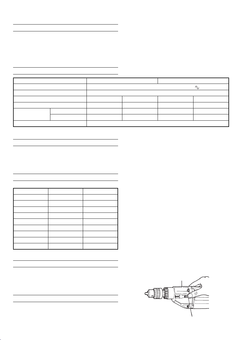
6. High- speed/Low- speed changeover:
Prior to changing speed, ensure that the switch is in
the OFF position, and the drill has
stop. To change speed, depress the shift Iock and
slide it in the appropriate direction, as indicated by the
arrow in Fig. 1. The numeral “1” engraved in the drill
body denotes low speed, the numeral “2” denotes high
speed.
position, the power tool will start
plastic
come to a complete
Gear cover
12
Shift lock
(push and slide)
Fig. 1
3
Page 4

7. IMPACT to ROTATION changeover: (Fig. 2)
The Impact Drill can be switched from IMPACT (impact
plus rotation) to ROTATION (ro tatio n only) by simply
turning the change ring.
When boring concrete, stone, tile or similar hard
materials, turn the change ring fully clockwise. The drill
head impacts against the material while
rotate.
When boring metal, wood or plastic, turn the change
ring fully counterclockwise. The drill simply rotates as
an ordinary electric drill.
Change ring
Rotation + impact
CAUTION
Do not use the Impact Drill in the IMPACT function if the
material can be bored by rotation only. Such action will
not only reduce drill effi ciency, but may also damage
the drill tip.
When changing over, ensure that the change ring is
turned as far as it will go.
8. Fixing the side handle.
Loosen the glip on the side handle, and attach the side
handle to the gear cover in a position convenient for
drilling. Match the projecting part of the handle to the
groove on the gear cover, and fi rmly tighten
To remove the side handle, loosen the glip, and rotate
the handle.
To attach a depth stopper on the side handle, insert
the stopper into the hexagon hole groove on the side
handle, adjust the position of the depth stopper in
accordance with the desired depth of the hole,
fi rmly tighten the glip.
Rotation
Fig. 2
Gear cover
1
2
continuing to
the glip.
and
PRACTICAL HANDLING PROCEDURES
1. Pressure:
Drilling will NOT be accelerated by placing heavy
pressure on the drill. Such action will only result in a
damaged drill bit, decreased drilling effi ciency and/or
shortened service life of the drill.
2. Using a large diameter drill bit:
The larger the drill bit diameter, the larger the
force on your arm. Be careful not to lose control of the
drill because of this reactive force. To maintain fi rm
control, establish a good foothold, hold the drill tightly
with both hands, and ensure that the drill is vertical to
the material being drilled.
3. When drilling completely through
When the drill bit bores completely through the material,
careless handling often results in a broken drill bit
or damage to the drill body itself due to the sudden
movement of the drill.
Always be alert and ready to release the pushing force
when drilling through the material.
the material:
reactive
4. Switch operation:
(1) VTP-16A:
By pulling the trigger switch and depressing the stopper,
the switch is held in the ON position for continuous
operation. To turn the drill OFF, pull the trigger switch
again and release.
(2) VTV-16:
The rotational speed of the drill bit can be controlled
by varying the
Speed is low when the trigger switch is pulled slightly
and increases as the switch is pulled more. Continuous
operation may be attained by pulling the trigger switch
and depressing the stopper. To turn the switch OFF, pull
the trigger switch again to
release the trigger switch to its original position.
5. Precautions on boring
The drill may become overheated during operation;
however, it is suffi ciently operable. Do not cool the drill
bit in water or oil.
6. Caution concerning immediately after use
Immediately after use, while it is
is placed on a location where considerable ground chips
and dust have accumulated, dust may occasionally be
absorbed into the Drill mechanism.
Always pay attention to this possibility.
amount that the trigger switch is pulled.
disengage the stopper, and
still revolving, if the Drill
MAINTENANCE AND INSPECTION
1. Inspection the drill bit
Continued use of a worn and/or damaged drill bit will
result in reduced drilling effi ciency and may seriously
overload the drill motor. Inspect the drill bit often and
replace it with a new bit as necessary.
2. Inspecting the mounting screws
Regularly inspect all mounting
they are properly tightened. Should any of the screws
be loose, retighten them immediately. Fail ure to do so
could result in serious hazard.
3. Inspecting the carbon brushes (Fig. 3)
The Motor employs carbon brushes which are
consumable parts. When they become worn to or near
the
“wear limit”, it could result in motor trouble. When an
auto-stop carbon brush is equipped, the motor will stop
automatically.
At that time, replace both carbon brushes with new ones
which have the same carbon brush Numbers shown in
the fi gure. In addition, always keep carbon brushes
clean and ensure
holders.
No. of
carbon
brush
that they slide freely within the brush
Wear limit
b mm
a mm
ab
43 17 6
73 17 7
screws and ensure that
No. of carbon brush
Usual carbon
brush
Auto-stop
carbon brush
Fig. 3
4
Page 5

4. Replacing carbon brushes
Disassemble the brush caps with a slotted-head
screwdriver. The carbon brushes can then be easily
removed.
5. Maintenance of the motor
The motor unit winding is the very “heart” of the power
tool. Exercise due care to ensure the winding does not
become damaged and/or wet with
6. Replacing supply cord
If the supply cord of Too l is damaged, the Too l must be
returned to Hitachi Authorized Service Center for the
cord to be replaced.
7. Service parts list
A: Item No.
B: Code No.
C: No. Used
D: Remarks
CAUTION
Repair, modifi cation and inspection of Hitachi
Too l s must be carried out by an Authorized Service
Center.
This Parts List will be helpful if presented with the power
tool to the Authorized Service Center when requesting
repair or other maintenance.
In the operation and maintenance of power tools, the
safety regulations and standards prescribed in each
country
MODIFICATIONS
Hitachi Power Too l s are constantly being improved
Accordingly, some par ts (i.e. code numbers and/or
NOTE
Due to HITACHI’s continuing program of research and
development, the specifi cations herein are subject to
change without prior notice.
must be observed.
and modifi ed to incorporate the latest technological
advancements.
design) may be changed without prior notice.
oil or water.
Power
5
Page 6

VTP-16A
ABCD
40 961781 2
41A 999073 2
1930733113G
2950284116WL “1”
ABCD
42 981586 2
43 981560 1 “42, 50”
39815661
48763191S-14
44 981562 1
45A 984367 1
59815681
69716571
46 946362 1
47A 99 4273 1
79395561
89815721
49 971667Z 1
50 949365 2 M4 × 5
48 930153 1
9 6003VV 1 6003VVCMPS2L
12 98157 1 1
10A 98159 2 1
51 9575 61 1
52 959140 1
53 956384 5 D4 × 20
14 97173 6 1
13 980 717 1 S -38
15 9395 43 1
57 93 8108 1
56 981373 2
58 954004 2 D4 × 16
55 981578 1
54 949423 6 M4
17 9716 61 1
19 608VVM 3 608VVC2PS2L
18 98157 3 1
16 98156 4 1
20 981570 1
61 –––––– 1
59 960266 1
21 949454 6 M5
63 981500 1 “EUROPE, AUS”
501 981579 1 “502, 503”
502 981580 1
503 983987 1
500 931844 1
60-1 953327 1 D8.8
22 955912 4 D5 × 45
63A 986277 1 “NZL, GBR, SAF”
60-2 938051 1 D10.1
220V-230V “36”
“FRA, ITA, GBR”
24 981574 1
23 942864 1 M5
25 981575 1
26 9 81576 1
27A 981577 1 M5
31 981585 1
28 981569 1
29 9 81581 1 “19, 30-32”
32 981588 1 M5 × 16
30 609VVM 1 609VVC2PS2L
33 - 1 9 816 11C 1 110V -12 7 V
36 930703 2
35A 991007 2 D5 × 60
37-1 98 1610 C 1 110V -127 V “36”
37-2 981610E 1 220V-230V “36”
33-2 9 81611E 1 2 20V-230V
33-3 981611F 1 240V
37-3 981610F 1 240V “36”
39 –––––– 1
37-5 981610H 1 240V “36” “AUS ”
37-4 981610G 1
37-6 9 81610J 1 110V “36” “GBR”
6
Page 7

VTV-16
ABCD
41 9815 86 2
42 982320Z 1 “41, 49”
1930733113G
2950284116WL “1”
ABCD
43 981562 1
44A 984367 1
39815661
48763191S-14
46 994273 1
45 946362 1
59815681
69716571
47 9 30153 1
48A 318344 1
79395561
89815721
51 959 141 1
49 949365 2 M4 × 5
50 957561 1
9 6003VV 1 60 03VVCMPS2L
12 981571 1
10A 981592 1
SUI”
52 982095 5 D4 × 20
13 9807 17 1 S- 38
57 981373 1
59 960266 1
58 930446 2 D4 × 16
54 938108 1
53A-1 324722 1
53A-2 324901 1 “GBR(230V), SAF,
17 9716 61 1
14 97173 6 1
15 9 395 43 1
19 608VVM 3 608VVC2PS2L
18 981573 1
16 98156 4 1
62 –––––– 1
60 930793 1
20 981570 1
63 986277 1 “SUI”
64 955908 1 “NZL”
501 981579 1 “502, 503”
502 981580 1
503 983987 1
61-1 9 53327 1 D8. 8
61-2 9380 51 1 D10.1
21 949424 4 M5
22 983981 4 D5 × 45
500 931844 1
GBR, HOL, AUT,
SUI, FRG, FRA”
24 981574 1
23 942864 1 M5
25 981575 1
26 981576 1
27A 981577 1 M5
31 9 81585 1
28 981569 1
29 981581 1 “19, 30-32”
32 981588 3 M5 × 16
30 609VVM 1 609VVC2PS2L
36 930703 2
35A 991007 2 D5 × 60
33-1 981611E 1 220V-230V
33-2 981611F 1 240V
37A-1 971720G 1 220V “36” “SAF,
37A-2 981610H 1 240V “36” “AUS ”
39 961781 2
38 –––––– 1
37A-3 980945 E 1 220V-230V “36”
40A 999073 2
37A-4 9809 45F 1 240V “36”
7
Page 8

Hitachi Koki Co., Ltd.
Shinagawa Intercity Tow er A, 15-1, Kona n 2-chome,
Minato-ku, Tokyo, Japan
911
Code No. C99013611 N
Printed in Japan
 Loading...