

Page 1
ENGLISH
TIME LAPSE
VIDEO CASSETTE RECORDER
VTL4024E
ENGLISH
Instruction manual
To obtain the best performance and ensure years of
trouble-free use, please read this instruction manual
completely.
Bedienungsanleitung
Bitte lesen Sie diese Bedienungsanleitung aufmerksam durch, um durch richtige Bedienung jahrelangen und störungsfreien Betrieb zu gewährleisten.
Mode d’emploi
Des performances optimales et un fonctionnement
à long terme seront assurés en appliquant les
présentes instructions après avoir entièrement lu ce
mode d’emploi.
Manuale di istruzioni
Per garantire la migliore prestazione e la più lunga
durata leggere attentamente e al completo le
seguenti istruzioni.
Manual de instrucciones
Para obtener el mejor funcionamiento y asegurar
años de uso libre de problemas, lea cuidadosamente este manual de instrucciones.
Gebruiksaanwijzing
Lees deze gebruiksaanwijzing aandachtig door voor
het verkrijgen van de beste prestaties en jarenlang
probleemloos gebruik.
Page 2

WARNING PRECAUTIONS
• Main supply:
AC 230V, 50 Hz only
• Do not remove panel covers by unscrewing them.
ENGLISH
There are no user-serviceable parts inside. Refer
all servicing to qualified service personnel.
• To prevent fire or shock hazard, do not expose
this unit to rain or moisture.
Safety
• Should any solid object or liquid fall into the cabinet, turn off the unit and have it checked by qualified personnel before operating it any further.
• To disconnect the mains lead, pull it out by the
plug. Never pull the lead itself.
Installation
• Choose a location in which air can pass through
the ventilation holes in the bottom, top and back
of the unit to prevent it from overheating.
• Do not install the unit near heat sources such as
radiators or air ducts or in a place subject to direct
sunlight, excessive dust, mechanical vibrations or
shock.
• Do not place heavy objects or heat-generating
objects on the VCR, or the cabinet could be damaged or the temperature inside the VCR could
rise, which could cause a fault.
• Never bring a magnet or magnetized object near
the VCR because it will adversely affect the performance of the VCR.
• Do not install the unit in an inclined position.
The unit is designed for operation in a horizontal
position.
• Do not place a container with water or any small
metal objects on the VCR: If spilled water or a
metal object, such as paper clip, enters the VCR, it
could cause a fire or electric shock.
Operation
• Condensation
If you pour a cold liquid into a glass, water vapor
in the air will condense on the surface of the
glass.
This is the condensation of moisture.
Condensation on the head drum, one of the most
crucial parts of the VCR, will cause damage to the
tape. The VCR should not be operated for at least
2 hours after being moved from a cold to a hot
environment to avoid condensation from occurring on the head drum.
Cleaning
• Be careful; when the surface of the case is wiped
with a volatile agent such as benzine, alcohol,
thinner, etc., or a chemically processed cloth, the
surface finish may be degraded or its coating may
peel off.
Repacking
• It is wise to save the packing materials and box in
case you ever need to ship or store your unit.
1
Page 3
FEATURES CONTENTS
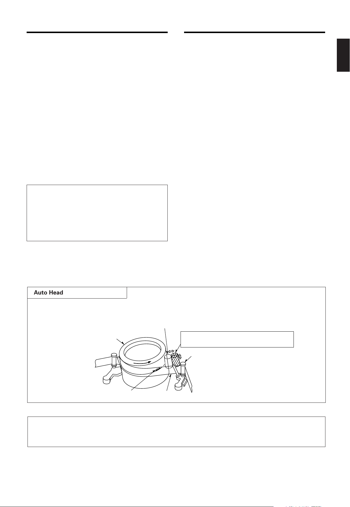
Touches the video head in the active position
Cylinder
Cleaning roller in the stand-by position
(Special material)
Tape guide
Tape
Video head
Recording
• Three Touch-Selectable Recording Speeds
(03, 12, 24)
• Recording Check
• Auto Recording Check
• On-Screen and On-Tape Time/Date Information
• 7-Day Programmable On/Off Timer
• “Alarm On” Output
• Usable Audio at 03, A12 and A24 hour Speeds
Playback
• Time-of-Alarm Memory and Alarm Index Search
• High Speed Visual Search
• Four Playback Speeds (03, A12, A24, 24)
• Still Field, Field-Advance, Field-Reverse and
Reverse Playback
Security
• About 720 hours Memory Protection
• Electronic Security Lockout
• Buzzer Function
Note: This recorder has a rechargeable battery
to maintain display functions and recording
mode within 720 hours in the event of power
loss. When the recorder is received, the unit
must be connected to power source for 48
hours to assure the battery has been adequately charged.
CONTROLS AND FUNCTIONS ..................................3
INSTALLATION ...........................................................7
EXTERNAL CONNECTIONS.......................................8
CASSETTE TAPES ....................................................10
SETUP ........................................................................11
SETTING THE TIME AND DATE ..........................12
SETTING [OPTIONS] ITEMS................................13
SUMMER TIME FUNCTION .................................13
SETTING THE TIMER............................................13
SETTING THE VCR FUNCTIONS .........................15
SETTING THE BUZZER.........................................16
SETTING THE ALARM..........................................17
ALARM MEMORY RECALL AND RESET ............18
OPERATION...............................................................19
TAPE RECORDING................................................19
REC CHECK............................................................19
AUTO REC CHECK ................................................19
TIMER RECORDING..............................................19
TAPE RECYCLE .....................................................19
ALARM RECORDING ............................................20
MASTER SYSTEM RESET....................................20
PLAYBACK.............................................................20
SHARPNESS CONTROL.......................................20
STILL PLAYBACK..................................................20
V.LOCK ADJUST...................................................20
PLAYBACK IN THE FIELD ADVANCE/
REVERSE MODES ............................................20
VISUAL SEARCH (High Speed Scan) .................21
ALARM INDEX SEARCH ......................................21
TO SECURE THE VCR ..........................................21
PROBLEM GUIDE......................................................22
SPECIFICATIONS ......................................................23
MAINTENANCE/INSPECTION SCHEDULES OF
MECHANICAL COMPONENTS ............................24
ENGLISH
Auto Head Cleaning System
This system cleans the video heads automatically when a cassette is inserted and ejected or the tape is
rewound in the recycle recording mode, to prevent dirt from accumulating on the heads.
REC CHECK before starting
In order to prevent the misrecording, press the PLAY button during recording. See page 19.
2
Page 4

[FRONT]
1
32
4
5
6
7
8
91011
12
13 14
15
16
DISPLAY (See page 5)
S
CONTROLS AND FUNCTIONS
ENGLISH
1. SLOW TRACKING CONTROL
2. TRACKING CONTROL
3. PROG./SHARPNESS CONTROL
4. DOWN/SOFT BUTTON
5. START/STOP BUTTON
6. UP/HARD BUTTON
7. SET BUTTON
8. CASSETTE COMPARTMENT
9. COUNTER RESET BUTTON
Adjust to optimize the picture quality in the SLOW
PLAY mode, e.g. 24 hours speed.
Adjust to optimize the picture quality during playback
at the 03, A12 and A24 hour speeds.
Press to select one of the seven programmable functions.
Press to select the picture quality with the UP/HARD
or DOWN/SOFT button to hard or soft during playback. See page 20 for SHARPNESS CONTROL.
Press to decrement, change or reverse to the
previous/lower value.
Press to adjust the picture quality to soft during playback.
Press to start or stop the programming of a programmable function. (Press once to start the programming
sequence and a second time to stop (end) it.)
Press to increase, change or advance to the next
higher value.
Press to adjust the picture quality to hard during playback.
Press to select the specific value which is to be
changed with the UP/DOWN buttons.
Press to clear the digital counter to “0000”.
10. RESET BUTTONS
Press these buttons at the same time to clear all
(microprocessor) functions.
Press the “S” button to reset the system. (This does
not erase the stored information.)
11. REC/PLAY HOURS BUTTONS
▲ (UP): Press to increase hours to the next
higher value.
▼ (DOWN): Press to decrease hours to the next
lower value. The tape speed will be
indicated as part of the monitor display.
12. TIMER BUTTON
Press after programming the TIMER for automatic
TIMER recording. See page 13 for TIMER programming.
13. V-POS (VERTICAL POSITION) / V-LOCK BUTTON
Press repeatedly to control the vertical position of the
programmable display on the monitor.
Press to reduce vertical jitter in the still play mode.
14. H-POS (HORIZONTAL POSITION) / V-LOCK BUTTON
Press repeatedly to control the horizontal position of
the programmable display on the monitor.
Press to reduce vertical jitter in the still play mode.
15. ALARM RESET BUTTON
Press to clear POWER LOSS information. When this
button is pressed when the Alarm Memory screen is
being displayed, the alarm memory is cleared.
16. ALARM INDEX BUTTON
Press this button to cause the INDEX indicator to light,
and set the VCR to the visual search mode (press
F.FWD or REWIND during playback mode) in this
state; the start of the alarm recorded can be located.
3
Page 5

ENGLISH
17
22
26
25
24
18
19
21
20
23
27
28
29
17. EJECT BUTTON
Press to remove the cassette. The EJECT button will
not operate in the RECORD mode.
18. STOP BUTTON
Press to stop the tape. The STOP button must be
pressed to end the RECORD and PLAY mode.
19. PLAY BUTTON
Press to play recorded material in the forward direction. Pressing this during recording makes it possible
to check recordings.
20.TIMER LED
The LED lights up during timer recording or timer
stand by mode.
21. ALARM LED
The LED lights up during alarm recording.
22. REC LED
The LED lights up during recording.
23. RECORD BUTTON
Press to start recording.
24. REVERSE PLAY BUTTON
Press to play recorded material at the 03 speed in the
reverse direction during the PLAY mode.
25. REWIND/VISUAL SEARCH BUTTON
Press to start rewind.
Press this button during playback and a reverse playback picture at high speed can be seen.
26. FAST FORWARD/VISUAL SEARCH BUTTON
Press to activate fast forward.
Press this button during playback and a forward playback picture at high speed can be seen.
27. FIELD REVERSE BUTTON
Press to reverse the tape by one field in the STILL
playback mode.
28. FIELD ADVANCE BUTTON
Press to advance the tape one field in the STILL playback mode.
29. STILL BUTTON
Press to momentarily stop tape motion in the play
mode. The STILL function allows close inspection of
individual scenes. See the description of STILL playback on page 20.
4
Page 6
37
39
40
38
30
TAB
TAPE END A
SPEED
TIMER
REC
ALARM
LOCK
INDEX
31 32 33 3634 35
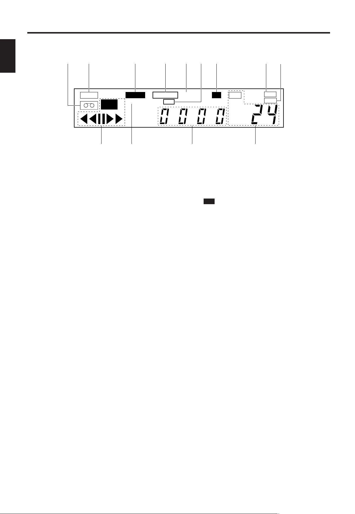
[DISPLAY]
HARD
41
SOFT
42
CONTROLS AND FUNCTIONS (Continued)
ENGLISH
30. TAPE-IN INDICATOR
Lights when a cassette is in the compartment.
31. TAB INDICATOR
Lights when a cassette without its safety tab is loaded.
32. ALARM INDICATOR
ALARM appears during alarm recording.
ALARM flashes when alarm recording ends.
33. TAPE END INDICATOR
Lights when the tape reaches the end during recording.
Note: “TAPE END” is not displayed when you have
selected REWIND, RE-REC in the “RECYCLE FUNCTIONS” menu in the alarm display or you have selected REWIND, STOP IF ALARM but an alarm recording
has not been made.
34. A INDICATOR
Lights when no video signal is input. Video signal
input will turn this indicator off automatically.
35. TIMER INDICATOR
This is lit during timer recording or TIMER stand-by
mode.
The indicator flashes in the following cases.
• A cassette is not loaded.
• A cassette without its safety tab is loaded.
• The timer has not been programmed.
36. LOCK INDICATOR
LOCK appears when the recorder is in the security
lock mode.
37. HARD INDICATOR
Lights when adjust the picture quality to hard during
playback mode and after setting.
38. SOFT INDICATOR
Lights when adjust the picture quality to soft during
playback mode and after setting.
39. VCR MODE INDICATORS
• appears during recording.
REC
• tt appears during the rewind mode.
• ss appears during the fast forward mode.
• tt (or ss) flashes during visual search.
• s appears during the playback mode.
• t appears during the reverse play mode.
•
• t
appears when the STILL button is pressed
❙❙
during play mode and disappears when the
STILL or PLAY button is pressed again.
(or ❙❙s) appears while the FIELD REV (or
❙❙
FIELD ADV) is held depressed in the still
playback mode.
Note: Still playback is restored when the
FIELD REV (or FIELD ADV) button is
released.
40. INDEX INDICATOR
INDEX appears when the ALARM INDEX button is
pressed.
INDEX disappears when the ALARM INDEX button is
pressed again.
INDEX flashes during alarm indexing.
41. DIGITAL COUNTER
Shows the tape counter. The counter does not count
during non-recorded sections of a tape.
In low temperature, display speed may be slow. The
count of a counter is ensured.
42. TAPE SPEED INDICATOR
Shows the tape speed.
5
Page 7
ENGLISH
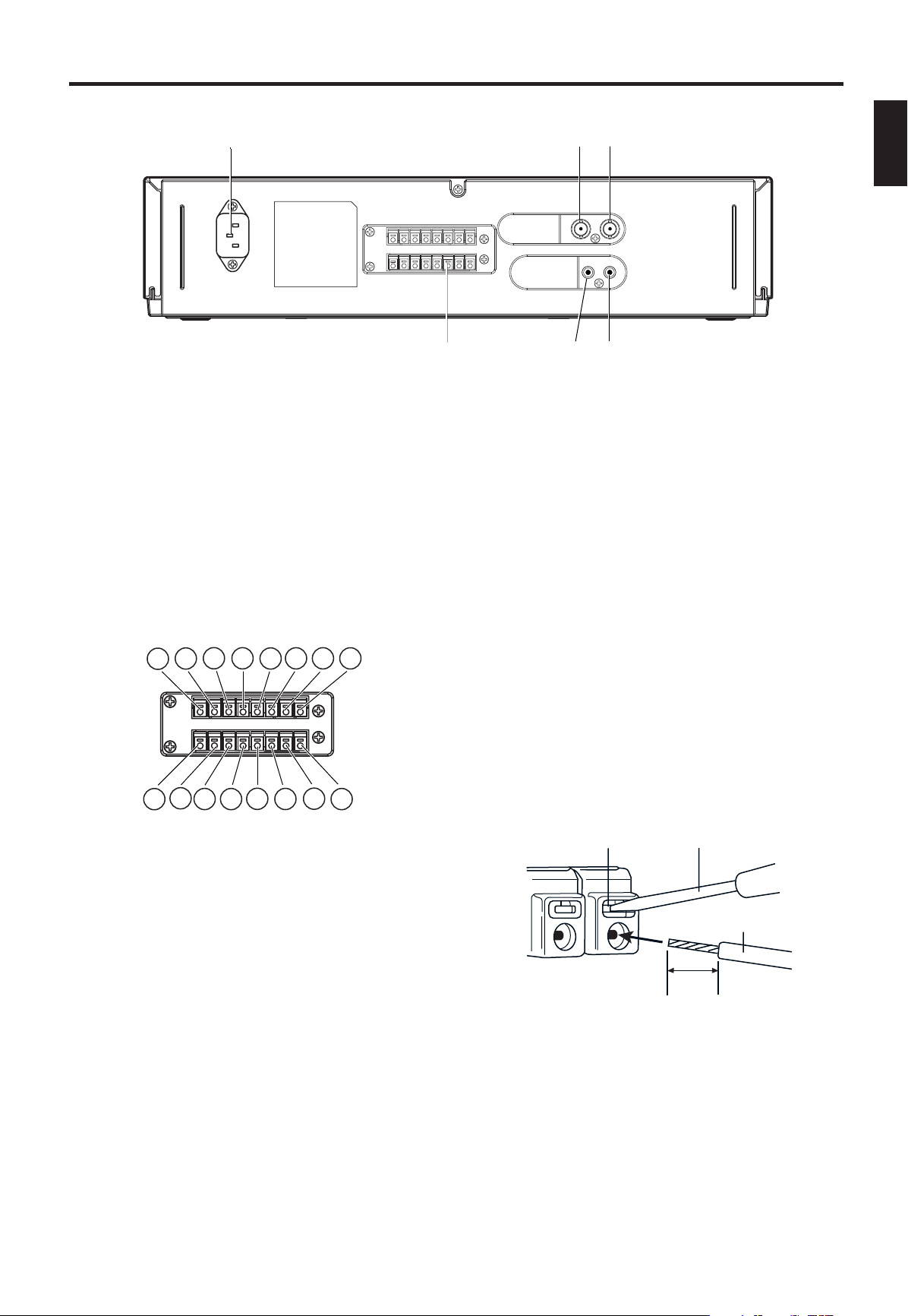
[REAR]
48
46
43
4544
47
6
1
5
1
4
1
3
1
2
1
1
1
0
1
9
8
6
7
5
4
3
2
1
ScrewdriverTab
Wire
10mm
43. AC INLET
44. VIDEO IN
45. VIDEO OUT
46. EXTERNAL INTERFACE (8 X 2-PIN) JACK
Receives video signal from a video camera or another
VCR.
For connection to monitor.
Connect an alarm switch, door sensor, etc.
q ALARM IN
w ALARM OUT
e NC
r TAPE END OUT
t TAPE END RESET
y WARNING OUT
u NC
i TIME ADJUST
o CAMERA SW OUT
!0 REC START IN
!1 NC
!2 NC
!3 REMOTE IN
!4 REC CHECK IN
!5 GND
!6 GND
47. AUDIO IN
Accepts an audio signal from a camera, external
sound equipment or another recorder (Line: –8 dBm,
50 kohm, unbalanced).
48. AUDIO OUT
Provides an audio output for a monitor or another
recorder (–9 dBm, 600 ohm, unbalanced).
CONNECTING WIRES
1. Strip off the wire cover by approx. 10mm.
2. Use a screwdriver, etc. to hold the tab, then
insert the wire.
• Push the tab firmly when inserting wire.
3. Release the screwdriver.
• The wire will be fixed.
Note: When disconnecting the wire, use the screwdriver again to hold the tab, then pull the wire out.
6
Page 8
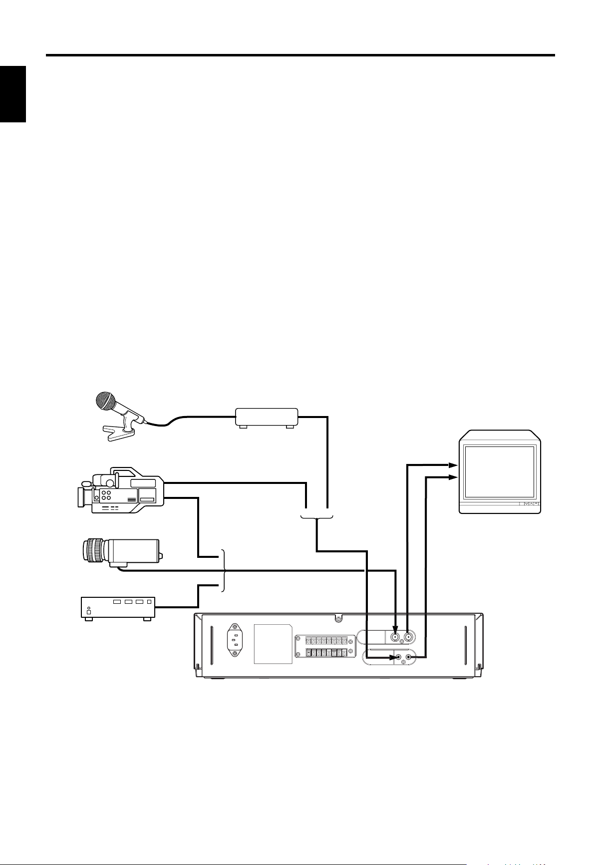
MONITOR
CAMERA
SWITCHER
VIDEO CAMERA/RECORDER
PREAMP
MICROPHONE
INSTALLATION
VIDEO CONNECTIONS
Use coaxial cables when connecting a camera and a
monitor to this VCR.
Note: Long cable runs to distant cameras may
ENGLISH
cause signal deterioration and/or sync discrepancies. If these problems occur, use video line
amplifiers and/or cameras having phase-adjustable
line-locked vertical sync.
Video Input
In single camera systems, connect the camera to the
Video IN BNC terminal on the VCR rear panel. Use
of a 2:1 interlace camera is highly recommended;
otherwise, the monitor will show vertical distortion
of the TIME/DATE characters.
In multiple camera systems, connect the switcher
output to the Video IN BNC terminal. Because multiple camera systems require synchronization, use
of cameras having line-locked vertical sync or a genlocked master drive/sync source is highly recommended. The use of vertical interval switchers
is also recommended.
Video Output
Connect the monitor to the Video OUT BNC terminal
on the rear panel.
AUDIO CONNECTIONS
Note: Audio recording can be performed at the 03,
12 and 24-hour recording speeds and audio playback at the 03, A12, and A24 speeds.
Audio In: Accepts an audio signal from a camera,
external sound equipment, or another recorder
(Line: –8 dBm, 50 kohm).
Audio Out: Provides an audio output for a monitor
or another recorder (–9 dBm, 600 ohm, unbalanced).
7
Page 9

EXTERNAL CONNECTIONS
ALARM IN GND
5
1
1
6
1
or
ALARM IN
You can connect an alarm switch with a resistance
of 1 kohm or less or a door sensor. Connect pin q
to !5 or !6 (ground) through the switches.
Note: Do not apply a voltage to pin q , !5 or !6.
ALARM OUT
Approx. 12V is applied to pin w during an alarm
recording.
Notes:
• When you have selected “PULSE” in the “ALARM
OUT” menu in the ALARM display, approx. 12V
pulses will be applied to the output after the
alarm recording ends.
• When you have selected “DURATION” in the
“ALARM OUT” menu in the ALARM display, no
voltage is applied after the alarm recording ends.
• The output impedance is approx. 100 ohm.
TAPE END OUT
Approx. 12V is applied to pin r when the tape
reaches the end.
Notes:
• This does not operate when you have selected
“REW, RE-REC” in the “RECYCLE FUNCTIONS”
menu in the ALARM display or you have selected
“REWIND, STOP IF ALARM” and no alarm recording has been made.
• The output impedance is approx. 100 ohm.
TAPE END RESET
The TAPE END OUT can be turned off when pin t is
shorted to pin !5 or !6.
Note: Do not apply a voltage to pin t , !5 or !6.
WARNING OUT
When an abnormality has occurred in this VCR,
approx. 5V is output to pin y to warn the user.
TIME ADJUST
When two or more of this VCR model are used, connect via these terminals. With only one VCR, specify TIME ADJUST: MASTER, in [OPTIONS] items on
the CLOCK SET display. Specify TIME ADJUST:
SLAVE (default setting at the factory) for all other
VCRs. Each time “2:00:05” is reached, the VCR set
to MASTER transmits pulses for adjustment to the
VCRs set to SLAVE. When the VCRs set to SLAVE
receive these pulses, their clocks will adjust to the
same time as the clock in the VCR set to MASTER.
Notes:
• Do not connect any device to pin e , u , !1 , !2.
• Be sure to set only one VCR to MASTER. If no VCR
is set to MASTER, or two or more VCRs are set to
MASTER, the TIME ADJUST function will not
operate normally.
ENGLISH
8
Page 10

EXTERNAL CONNECTIONS (Continued)
5±2 ms
0~0.4V
4.5~5.5V
STOPorPLAY STILL REW F.ADV F.F RECMODE UP
516
1
3
1
CAMERA SW OUT
Pin o outputs the following signal each time a onefield image is recorded. You can combine this with
a video camera switcher which can be controlled
ENGLISH
externally.
The output timing can be specified using the SELECTION MENU screen.
REC START IN
Recording is started when 5 ~ 12V is applied to pin
!0.
REMOTE IN
This VCR can be remote controlled when the following circuit is connected to pin !3.
The above resistance values have a tolerance of
±2%.
REC CHECK IN
Recording can be checked when pin !4 is shorted to
pin !5 or !6 during recording mode. The recorded
material is played back for several seconds so that
you can check whether recording is made normally
or not.
9
Page 11

CASSETTE TAPES
SAFETY TAB SLOT
Tape Insertion Position
TOP OF CASSETTE
(THIS SIDE UP)
INSERT
SAFETY TAB
Video Cassette Safety Tab
TO PREVENT
ACCIDENTAL
ERASURE, BREAK
OFF THE TAB
TO RECORD AGAIN,
COVER THE HOLE
WITH TAPE
TAPE LIFE
Slower speed operation in time lapse recording
applies stress to video tape. Tapes should be
inspected and, if necessary, discarded after the total
number of complete tape passes (recording and
playback) exceeds the following limits:
Tape Speed Complete Tape Passes
03, 12, 24 50
INSERTING A CASSETTE
Note: This is the first step in all VCR operations.
The VCR will not operate without a cassette in place.
To insert a cassette push the cassette through the
cassette compartment door until the VCR mechanism pulls it into the compartment.
The tape-in indicator turns on.
VIDEO CASSETTE SAFETY TAB
To prevent accidental erasure of recorded material,
remove the safety tab from the lower left corner of
the cassette.
Recording is impossible when the safety tab is
removed.
Notes:
• The TAB indicator lights when a cassette without
its safety tab is loaded.
• To record again on a cassette that has its safety
tab removed, cover the tab hole with tape. In the
TIMER mode, the TIMER indicator will flash on
and off if the cassette is inserted without its safety
tab slot covered or intact.
ENGLISH
REMOVING A CASSETTE
Before removing a cassette, rewind the tape completely.
To remove a cassette, press the EJECT button. The
cassette will come partially out of the compartment
so you can pull it out.
Important
“Avoid using cassette box fabricated out of
transparent material.”
This is to prevent occurrence of any incorrect
operation due to sensor's misdetection.
TAPE LENGTH
The total recording time at each of the three tape
speeds depends on the length of the tape used.
The table below shows:
1. The total recording time that can be recorded at
each tape speed mode on E90 and E180 tapes.
2. The pictures per second at each speed.
3. The speeds at which audio can also be recorded.
Use the table to select the tape length which gives
the best compromise between tape cost, total
recording time, and elapsed time between pictures.
Tape Speed Mode 03 12 24
Total Recording
Hours
Pictures/
Second
E90 1.5 7.5 13.5
E180 3 15 27
RECORD 50 10 5.6
PLAYBACK
50 10 5.6
Audio
RECORD Yes Yes Yes
PLAYBACK
Yes Yes (A12) Yes (A24)
Note: The values in this table are approximate.
10
Page 12

SETUP
TIME/DATE DISPLAY
CLOCK SET
TIMER DISPLAY
SELECTION MENU 1
Initial Program Function Display Formats
01
–:1–010
00
A00M30ON
MON
0
M
ON :
✽✽
03
1
0
0
0
0
0
0
0
0
0
0
0
0
0
0
:00 :00
a
032:00 :00
a
033:00 :00
a
034:00 :00
a
035:00 :00
a
036:00 :00
a
037
,
THU:
✽✽
,
TUE :
✽✽
,
FR I :
✽✽
,
SUN:
✽✽
,
W
ED :✽✽,
SAT :
✽✽
,
:00 :00
a
ELECT
:
M
ODE
SE EEADPCH S
X5
M
S
R:
EVID O
O
T
AU
W
RM:E~CA A S
12
ENUION
SELECTION MENU 2
ALARM DISPLAY
ALARM MEMORY DISPLAY
DULR
AR
M
:TION UMAL
AN
S
SPE D :
03
A
LAR
M
A
LAR
M
A
LAR
M
A
A
RE SIND,
W
DUFURTION
ION
A
E
YDR:AE
:OTU
YE
SET
TOPNCIF
TCLECYRE
S
LAR
MMM
1
A00A
2
3
4
5
6
7
8
9
ORYE
01
–:1–010
000
LOCKCSET
TYPO:E
ADJ :US S LAV ETTI
M
E
FUL LSD
PT I OONS
ELECT
EN
E
SEL
TA NEPTD
OF
M
S
EO:
TR UOBL
F
F
OFF
OFF
:
ZBUZ E
O
I
CRT
I:VNEODO
E:RAU C CHEC K
OF
ENUION
F
LAR
M
A
O:TU
OF
:
:
(()
)
)
)
)
)
)
(
(
(
(
(
On-Screen displays are provided to aid setup of the
programmable functions. The seven functions on
the Program Menu appear individually on the monitor in this order.
ENGLISH
1. TIME/DATE
2. CLOCK SET
3. TIMER
4. SELECTION MENU 1
5. SELECTION MENU 2
6. ALARM
7. ALARM MEMORY
Note: If the VCR is not turned on for about 720
hours after the built-in battery is fully charged (after
the VCR is turned on for more than 48 hours), the
TIME/DATE display will be cleared.
ESTABLISHING THE PROGRAM MODE
The TIME/DATE display appears on the monitor
screen when the power cord is first plugged in.
SELECTING A FUNCTION TO BE PROGRAMMED
The program menu will always begin with the TIME/
DATE function, followed by the CLOCK SET, TIMER,
SELECTION MENU 1, SELECTION MENU 2,
ALARM, and then the ALARM MEMORY functions.
Although the program menu always follows this
order, it is possible to skip any of the available functions during the selection process.
To select the desired program function (and to move
from one program function to the next), press the
PROGRAM button repeatedly until the desired function display format appears on the monitor.
After the desired function has been selected, follow
the corresponding procedure to set that function.
SETTING THE PROGRAM FUNCTION(S)
The first step in each programming procedure is:
“Press the START/STOP button”. The system
allows up to five minutes for any one function setting to be completed after the START/STOP button
is pushed. If no change/setting is entered within the
five minutes period, the unit will automatically exit
the selected program function and return the TIME/
DATE display to the monitor. (If this happens, reselect the desired program function, and follow the
programming procedure for that function.)
The following procedures for setting VCR functions
assume that the desired function has already been
selected.
Notes:
1. During programming, holding the SET, UP, or
DOWN button will move/change the displayed
information at a rapid rate.
2. The position of the TIME/DATE display on the
monitor can be adjusted by using the H-POS and
V-POS button on the front panel.
11
Page 13

SETTING THE TIME AND DATE
MON1 –:1 – 010
000
LOCKCSET
TYPO:E
ADJ :US SLAV ETTI
M
E
FUL LSD
PT I OONS
TIME (HOUR, MINUTE, SECOND)
DATE (DAY, MONTH, YEAR)
DAY OF WEEK: Corrected
automatically to
match the input
date.
CLOCK SET Display Format Description
OSD TYPE (FULL, HALF or OFF)
TIME ADJUST (MASTER or SLAVE)
:
0
Use the CLOCK SET display to set the date and time.
1. Press the START/STOP button so that [CLOCK
SET] flashes on/off.
2. Press the SET button. The day flashes on/off.
3. Press the UP or DOWN button until the desired
number appears on the monitor.
4. Press the SET button. The month flashes on/off.
5. Press the UP or DOWN button until the desired
number appears on the monitor.
6. Press the SET button. The year flashes on/off.
7. Press the UP or DOWN button until the desired
number appears on the monitor.
8. Press the SET button. The hour flashes on/off.
9. Press the UP or DOWN button until the desired
number appears on the monitor.
10. Press the SET button. The minutes flash on/off.
11. Press the UP or DOWN button until the desired
number appears on the monitor.
12. Press the START/STOP button: the seconds will
start counting and the clock will start. [CLOCK
SET] will flash on/off again at this time.
13. Press the START/STOP button twice so that
flashing [CLOCK SET] changes to a steady light.
14. Press the PROGRAM button continuously so that
the TIME/DATE display appears.
Notes:
• Perform the same procedure as when setting the
time and date to make corrections after having
set them. The minutes flash on/off when the SET
button is pressed (in step 2 above).
• To record time and date on the tape, display them
on the monitor screen. If they are not displayed
on the monitor, they cannot be recorded on the
tape.
ENGLISH
12
Page 14

SETUP (Continued)
PROGRAM NUMBER
TIMER RECORDING TIME START/STOP
TIMER RECORDING TAPE SPEED
DAY OF WEEK AND PROGRAM NUMBER
1 :TIMER will record for the time set for PROGRAM NUMBER 1
2 :TIMER will record for the time set for PROGRAM NUMBER 2
3 :TIMER will record for the time set for PROGRAM NUMBER 3
4 :TIMER will record for the time set for PROGRAM NUMBER 4
5 :TIMER will record for the time set for PROGRAM NUMBER 5
6 :TIMER will record for the time set for PROGRAM NUMBER 6
7 :TIMER will record for the time set for PROGRAM NUMBER 7
✽ :No recording
TIMER Display Format Description
M
ON :
✽✽
03
1
0
0
0
0
0
0
0
:00
a
03
2
:00
a
03
3
:00
a
03
4
:00
a
03
5
:00
a
03
6
:00
a
03
7
,
THU:
✽✽
,
TUE :
✽✽
,
FR I :
✽✽
,
SUN:
✽✽
,
W
ED :✽✽,
SAT :
✽✽
,
:00
0
0
0
0
0
0
0
:00
:00
:00
:00
:00
:00
:00
a
SETTING [OPTIONS] ITEMS
OSD TYPE: You can select the TIME/DATE display
from three options: FULL, HALF and OFF.
ENGLISH
FULL
DATE
POWER LOSS (IF SENSED)
DAY OF WEEK
ALARM COUNT*
210– 2–011
8: 5:46 031
* The ALARM Count Number records alarms from 0 to 99
and then resets to 0 and continues counting.
PL
RECORDING SPEED (IN TOTAL HOURS)
TIME
00A
T
H
U
T
L
SECURITY LOCK (IF ACTIVATED)
TIMER (IF ON)
HALF
DATE
No display
TIME ADJUST: When two or more of this VCR
model are connected to pins i TIME ADJUST of
each EXTERNAL INTERFACE jack, the clocks in both
VCRs can automatically be set to the same time
(TIME ADJUST function).
To use the TIME ADJUST function, set one VCR to
MASTER and any others to SLAVE.
1. Press the START/STOP button twice so that
[OPTIONS] flashes on/off.
2. Press the SET button twice so that the TIME
ADJUST: setting flashes on/off.
3. Press the UP or DOWN button to select the setting
(SLAVE or MASTER).
4. Press the START/STOP button again. The selected setting will light.
Notes:
• You can set OSD TYPE and TIME ADJUST after
you have set the date and time.
• The TIME ADJUST function operates only when
the VCRs are turned on. Therefore, turn the VCRs
on around 2:00:05. This function will not operate
if the times on the MASTER and SLAVE VCRs drift
by more than one hour and 30 minutes.
210– 2– 011
8: 5:461
TIME
OFF
No display
1. Press the START/STOP button twice so that
[OPTIONS] flashes on/off.
2. Press the SET button so that the OSD TYPE: setting flashes on/off.
3. Press the UP or DOWN button to select the setting
(FULL, HALF or OFF).
4. Press the START/STOP button again. The selected
setting will light.
SUMMER TIME FUNCTION
Press the FIELD ADV and UP buttons simultaneously
in the stop mode; the hour display will be counted
up by one.
Press the FIELD ADV and DOWN buttons simultaneously to count the hour display down by one.
You can change the hour display in one-hour steps
without any limit by pressing the above buttons.
Note: Summer time cannot be set unless TIME/
DATE is displayed or during the timer recording
standby mode.
SETTING THE TIMER
To set the 24 Hour On/Off Timer function
13
Page 15

1. Press the START/STOP button.
Example
•••••
Record
Time
Program number 1
Program number 2
Program number 3
When recording of program
number 3 is terminated, program
number 2 will be recorded for its
remaining time.
The program number (1) flashes on/off.
2. Press the SET button. The start hours flash on/
off.
3. Press the UP or DOWN button until the desired
number appears on the monitor.
4. Press the SET button. The start minutes flash
on/off.
5. Press the UP or DOWN button until the desired
number appears on the monitor.
6. Press the SET button. The stop hours flash on/
off.
7. Repeat steps 3 through 5 to set the stop hours
and minutes.
8. Press the SET button. The timer recording
speed flashes on/off.
9. Press the UP or DOWN button until the desired
number appears on the monitor.
10. Press the SET button after setting the timer
recording speed. The program number of the
next lower line flashes on/off.
11. Repeat steps 2 through 9 to set the program to
the other program numbers.
12. Press the SET button after setting the program
numbers (1) through (7).
The two program event locations of MON flash
on/off.
13. Press the SET button. The first program event
location of MON flashes.
14. Press the UP or DOWN button until the desired
program number appears on the monitor.
15. Press the SET button. The other program event
location of MON flashes on/off.
16. Press the UP or DOWN button until the desired
program number appears on the monitor.
Notes:
• If you do not need to timer record two events
a day, mark either event with an asterisk (✽).
• If two asterisks are displayed, no timer record-
ing is made on that day.
17. After setting two program event locations of
MON, press the SET button. The two program
event locations of the next day of the week
flashes on/off.
18. Press the SET button. The first program event
location of the next day flashes.
19. Repeat steps 12 through 16 to set the program
event locations up to SUN.
20. Press the START/STOP button when the TIMER
has been set.
Notes:
1. Programming the TIMER function does not activate it. See TIMER recording, page 19.
2. To record the time and date press the PROGRAM
button to display them.
3. When the preset START time is later than the
STOP time, the recording will be made into the
following day.
4. When the START time and STOP time are the
same, a recording will not be made.
5. When the programs for timer recording overlap
each other, recording will be switched to the program with the later recording start time.
6. When two programs have the same start time,
the program number with the longest stop time
has priority.
■ To correct information
1. Press the START/STOP button.
2. Press the UP or DOWN button repeatedly until
the item to be corrected (Program number or
program event location of day of the week)
flashes on/off.
3. When the section to be corrected flashes on/off,
press the SET button.
• Press the SET button again so that only the
digit to be corrected flashes on/off.
4. Press the UP or DOWN button to correct the set
information.
5. After completing the correction, press the
START/STOP button.
ENGLISH
14
Page 16

SETUP (Continued)
VIDEO MODE (AUTO, COLOUR, B/W)
• Use during recording or playback if the video signal is unstable,
etc.
AUTO:
COLOUR:
B/W:
The unit automatically detects the type of the video
input or playback signal and switches to the colour
or black-and-white video signal mode, as appropriate.
Selects the colour video signal mode.
Selects the black-and-white video signal mode.
12~:
ALL:
03 ONLY:
The pulses are output during recording at 12 or a
longer speed mode.
The pulses are output during recording in all modes.
The pulses are output during recording at the 03
speed mode.
SEARCH SPEED (3, 5, 7 or 9 times the normal speed)
• You can select the visual search speed.
CAMERA SW (12~, ALL, 03 ONLY)
• You can select the timing with which pulses are output to
switch the camera.
SELECTION MENU 1 Format Description
ELECT
:
M
ODE
SE EEADPCH S
X5
M
S
R:
EVID O
O
T
AU
W
RM:E~CA A S
12
ENUION
SETTING THE VCR FUNCTIONS
The SELECTION MENU 1 screen allows you to select the VCR operations and functions to match the applications.
ENGLISH
1. Press the START/STOP button.
The VIDEO MODE option “AUTO” flashes on/off.
2. Press the SET button repeatedly until the item
the setting of which you want to change flashes.
3. Press the UP or DOWN button to select the value
or setting you want.
4. After selecting, press the START/STOP button.
15
Page 17

SETTING THE BUZZER
ELECT
EN
E
SEL
TA NEPTD
OF
M
S
EO:
TR UOBL
F
F
OFF
OFF
:
ZBUZ E
O
I
CRT
I:VNEODO
E:RAU C CHE CK
OF
ENUION
F
LAR
M
A
O:TU
OF
TAPE END (ON or OFF)
• To specify whether buzzer turns on or off, synchronized with
pin TAPE END OUT of the EXTERNAL INTERFACE jack.
ON:
OFF:
Buzzer will keep sounding when tape reaches the end
during recording.
Buzzer will not sound even when tape reaches the end.
TROUBLE (ON or OFF)
• To specify whether buzzer turns on or off when abnormality
occurs in this VCR.
ON:
OFF:
Buzzer will keep sounding if abnormality occurs.
Buzzer will not sound even if abnormality occurs.
NO VIDEO (ON or OFF)
• To specify whether buzzer turns on or off when no video signal
is input during recording.
ON:
OFF:
Buzzer will keep sounding when video signal input stops.
Buzzer will not sound even when input stops.
AUTO REC CHECK (ON or OFF)
• To specify whether buzzer turns on or off if recording is
abnormal after the AUTO REC CHECK function.
ON:
OFF:
Buzzer will keep sounding if recording is abnormal.
Buzzer will not sound even if recording is abnormal.
ALARM OUT (ON or OFF)
• To specify whether buzzer turns on or off when alarm is output.
ON:
OFF:
Buzzer will keep sounding if alarm is output.
Buzzer will not sound even if alarm is output.
SELECTION MENU 2 Format Description
4
This VCR has a buzzer function.
Use SELECTION MENU 2 to select the times when you wish buzzer to sound.
Note: “OFF” is specified for all buzzer options at the factory.
ENGLISH
1. Press the START/STOP button.
The TAPE END option “OFF” flashes on/off.
2. Press the SET button repeatedly until the item
the setting of which you want to change flashes.
3. Press the UP or DOWN button to select the value
or setting you want.
4. After selecting, press the START/STOP button.
To stop buzzer:
1. When lights in the VCR display, press
TAPE END
the EJECT button: The tape will come out and
the buzzer will stop.
2. When “A” lights in the VCR display and also “NO
VIDEO” appears on the monitor screen, the
buzzer will stop when video signal is input.
3. When “REC CHECK” appears on the monitor
screen, press the STOP button: The buzzer will
stop.
4. When alarm indicator flashes in the VCR
ALARM
display, press the ALARM RESET button: The
buzzer will stop.
5. If buzzer function varies in any of the above cases,
the VCR may be abnormal. Press the RESET buttons simultaneously: The buzzer will stop.
However, note carefully that all settings will
return to initial values set at the factory.
Note: You can also stop buzzer by switching ON to
OFF in SELECTION MENU 2.
16
Page 18

SETUP (Continued)
DULR
AR
M
:TION UMAL
AN
S
SPE D :
03
A
LAR
M
A
LAR
M
A
LAR
M
A
A
RE SIND,
W
DUFURTION
ION
A
E
YDR:AE
:OTU
YE
SET
TOPNCIF
TCLECYRE
S
ALARM Display Format Description
DURATION: User programmable length or time the unit
stays in the alarm record mode. (MANUAL, 5 SEC, 15
SEC, 30 SEC, 1 MIN, 3 MIN, 5 MIN, 10 MIN, 30 MIN, 60
MIN or TAPE END)
ALARM RECORDING TAPE SPEED
(03, 12 or 24)
ALARM READY (YES or NO)
RECYCLE FUNCTIONS
(“REWIND, STOP IF ALARM”, “REWIND, STOP” or
“REWIND, RE-REC”)
ALARM OUT
(DURATION or PULSE)
SETTING THE ALARM
The ALARM function allows the user to set the
recording duration, speed to be recorded and tape
recycle for alarm recordings. When a contact clos-
ENGLISH
ure occurs at the ALARM IN input, the VCR automatically enters the RECORD mode at the pre-programmed ALARM recording speed. (See Alarm In,
page 8 for a complete description of the ALARM
sequence.) The ALARM recording duration can last
from 5 seconds to TAPE END, or until the contact
closure is reopened.
The ALARM recording speed can be pre-programmed to 03, 12 or 24.
The checking signal is automatically recorded on the
tape at the beginning of each ALARM recording.
Later, you can easily locate the start of each recording by using these signals when watching a recorded content. See “ALARM INDEX SEARCH” on
page 21 for details.
The TIME/DATE display is set as follows during
ALARM display.
— ALARM stars (✽) will replace the colons (:).
— The recording speed will be changed to 03, 12 or
24 which was selected at the “SPEED” setting in
the ALARM display.
Notes:
• When the ALARM recording ends, the unit will
return to the original record speed and restore the
original record speed values to the TIME/DATE
displays.
• Select 03 at the “SPEED” setting when the dur-
ation is within 30 seconds. If the 12 or 24 speed is
selected, electronic “marks” are not recorded on
the tape and alarm index search will not operate.
1. Press the START/STOP button. The duration setting flashes on/off.
2. Press the UP or DOWN button until the desired
setting appears on the monitor. (MANUAL, 5,
15, 30 SEC, 1, 3, 5, 10, 30, 60MIN, TAPE END)
3. Press the SET button. The record speed setting
flashes on/off.
4. Press the UP or DOWN button until the desired
setting appears on the monitor. (03, 12 or 24
hours.)
5. Press the SET button. The alarm ready setting
flashes on/off.
6. Press the UP or DOWN button to select the
alarm ready function. (YES or NO)
Select “YES” if you want to start alarm recording even in the normal record or stop mode.
Select “NO” if you do not want alarm recording
in the stop mode.
7. Press the SET button. The alarm out setting
flashes on/off.
8. Press the UP or DOWN button to select the
alarm out function. See “ALARM OUT” on page
8 for details. (DURATION or PULSE)
9. Press the SET button.
The RECYCLE position flashes on/off.
10. Press the UP or DOWN button to select the
mode at the end of tape. See “TAPE RECYCLE”
on page 19 for details.
11. Press the START/STOP button.
Programming for the ALARM has been completed.
Note: To record the time and date, press the PROGRAM button so they are displayed.
17
Page 19

ALARM MEMORY RECALL AND RESET
ALARM MEMORY Display Format Description
LAR
MMM
1
A00A
2
3
4
5
6
7
8
9
ORYE
Displays the number of alarm
inputs that have occurred.
Counts up to 99 inputs.
ALARM COUNT :
ALARM MEMORY:
1: Displays the date/time of the first alarm recording.
2~9: Displays the 8 dates/times of the last alarms to have
occurred including the last alarm recording.
The VCR signals that an alarm has occurred by
flashing the ALARM indicator. If a power loss has
occurred, a “PL” will appear in the first line of the
TIME/DATE 1 display.
To recall the ALARM display:
1. Press the PROGRAM button until the ALARM
MEMORY display appears on the monitor.
2. Log the time/date information from the ALARM
memory.
ENGLISH
After checking the alarm times and dates, press the
ALARM RESET button to clear the ALARM memory.
Notes:
• When the ALARM RESET button is pressed once,
if “PL” is flashing, “PL” will disappear. Press the
button again to clear the ALARM memory.
• When “PL” is not flashing, press the ALARM
RESET button once to clear the ALARM memory.
18
Page 20

OPERATION
210– 2– 011
8
NO V I DE O
: 5:461
TAPE RECORDING
CAUTION: Recording over existing recorded ma-
terial will completely erase that material. To prevent
ENGLISH
accidental recording over the end of a previous
recording, advance the tape several seconds before
beginning the next recording.
1. Insert a video cassette; be sure the cassette
safety tab is intact, or the tab slot is covered.
2. Press the REC/PLAY HOURS button until the
desired tape speed is observed on the tape speed
indicator.
3. Press the RECORD button to start recording.
4. Press the STOP button to stop recording.
Notes:
— The tape speed mode can be changed during
recording.
— AUDIO can be recorded at 03, 12 and 24 tape
speed modes.
—“NO VIDEO” will be
displayed when no
video signal input during recording.
This VCR offers two special recording functions,
TIMER recording and ALARM recording.
REC CHECK
This function allows you to check whether the pictures are being recorded normally or not during
recording.
When the PLAY button is pressed during recording,
the recorded picture is played back for several seconds. Then recording will continue.
AUTO REC CHECK
If tape reaches the end during recording, this function allows the VCR to automatically rewind the tape
and play it back for several seconds. If AUTO REC
CHECK detects from playback that the tape has been
normally recorded, the VCR will rewind the tape to
its start. If AUTO REC CHECK detects that the tape
has not been normally recorded, it will output a signal to pin y WARNING OUT of the EXTERNAL
INTERFACE jack; in addition, “REC CHECK” will
appear at the top left of the monitor screen.
Note: If “AUTO REC CHECK: ON” is specified in
SELECTION MENU 2, the buzzer will keep sounding
when tape has not been normally recorded.
TIMER RECORDING
This VCR can also record at any speed on TIMER
command (turn on/off to record during any 24-hour
time period). To program the TIMER function, refer
to pages 13 and 14.
To operate the TIMER recording function, follow the
tape recording procedure, step 1, then press the
TIMER button to activate the programmed TIMER
function.
TAPE RECYCLE
The “RECYCLE FUNCTIONS” in the ALARM display
determine the mode after recording at the end of
tape.
When the “REWIND, STOP IF ALARM” is selected:
— If no alarm has been received during the recorded
period, the VCR automatically rewinds to the
beginning of tape and continues recording.
— If an alarm has been received via the ALARM IN
terminal during the recording period, the VCR
automatically rewinds to the beginning of tape
and then enters the STOP mode.
Recycle
REWIND, STOP
IF ALARM
Alarms Present on
Recorded Tape
YES Rewinds tape, then stops. Will not respond to alarm input.
NO
YES
Rewinds tape then continues to record.
Rewinds tape, then stops. Will not respond to alarm input.
REWIND, STOP
Rewinds tape, then stops. Will not respond to alarm input.
Rewinds tape then continues to record.
Rewinds tape then continues to record.
REWIND,
RE-REC
NO
YES
NO
When “REWIND, STOP” is selected:
— When the tape reaches the end during recording,
the VCR automatically rewinds to the beginning
of tape and enters the STOP mode.
When “REWIND, RE-REC” is selected:
— When the tape reaches the end during recording,
the VCR automatically rewinds to the beginning
of tape and continues recording.
Note: When “REWIND, STOP” or “REWIND, RE-
REC” is selected, the VCR operates whether an
alarm has occurred or not.
Results
19
Page 21

ALARM RECORDING
SOFT
SOFT
21
HARD
1
HARD
20
This VCR can automatically record at one of three
speeds (03, 12 or 24) on ALARM command.
To program the ALARM function refer to page 17.
The remote/contact switch must be connected to the
VCR. See page 8.
To operate the ALARM recording in the stop mode:
follow the tape recording procedure, step 1, then
select “YES” of the ALARM READY menu in the
ALARM display.
MASTER SYSTEM RESET
Press the two reset buttons simultaneously to provide a MASTER SYSTEM RESET. Use to reset
abnormal displays and operations. The programmable features must be re-programmed.
PLAYBACK
1. Rewind the tape to the desired beginning point.
(Press the REWIND button, and observe the digital counter until the desired number appears.)
Press the stop button.
2. Press the REC/PLAY HOURS button until the
desired tape speed is observed on the tape speed
indicator.
3. Press the PLAY button to initiate forward playback.
To select reverse playback, press the PLAY button and then press the REVERSE PLAY button.
Forward playback resumes when the PLAY button is pressed.
Notes:
• When the REVERSE PLAY button is pressed in
the forward playback mode to set the VCR to
the reverse playback mode, the first several
frame images may be distorted.
• The VCR will automatically enter the STOP
mode if the reverse play is continued for
approx. 1 minute.
4. Press the STOP button to stop playback.
Notes:
— The tape speed mode can be changed during
playback.
— When a picture recorded in the 03 mode is played
back in the A12 or A24 mode, it includes noise. It
is recommended that you play back pictures
recorded in the 03 mode at modes higher than 24.
— When the tape reaches the end, the unit auto-
matically rewinds to the beginning of the tape
and then goes to the STOP mode.
— If the monitor display exhibits distortion in the
upper part of the picture, adjust the horizontal
hold control on the monitor.
— Adjust the SLOW TRACKING control to minimize
noise when playing back at slow speed (24 hours)
or in the FIELD ADVANCE/REVERSE mode.
— The playback picture is not stable and has some
noise at A12 or A24 mode. And in these modes
TRACKING control is not effective.
SHARPNESS CONTROL
When the SHARPNESS CONTROL button is pressed
during playback, then within 5 seconds press the
SOFT or HARD button to change picture quality to
soft or hard by 5 steps.
LCD display:
STILL PLAYBACK
When the STILL button is pressed during playback,
a still picture can be seen. To start again press STILL
or PLAY button and the VCR will continue playback.
Notes:
• When still playback continues for more than 5
minutes, the AUTO-PROTECT circuit operates and
the VCR will enter the STOP mode automatically.
• If the picture shakes up and down during still
playback, press the V.LOCK buttons.
V.LOCK ADJUST
If the picture shakes up and down during still playback, adjust the picture by the following procedure.
1. Play back a tape, recorded in the 03 mode, in the
still playback mode.
• With some TVs, if the V.LOCK buttons are
pressed when playing a tape recorded in
modes other than 03, shaking of the still picture may not stop.
2. Press the V.LOCK buttons so the shaking of the
picture stops.
Note: Shaking of the picture may not be stopped
completely depending on the TV used.
PLAYBACK IN THE FIELD ADVANCE/REVERSE
MODES
When you press the FIELD ADVANCE or FIELD
REVERSE button during still playback mode, one
field at a time can be seen.
Operates only after STILL button has been pressed.
Notes:
• An AUTO-PROTECT circuit automatically returns
the unit to the STOP mode if the STILL or PLAY
button is not pressed again or if FIELD ADVANCE
or FIELD REVERSE button is not pressed in any
five minute period.
• When the FIELD REVERSE button is pressed in
the still playback mode to set the VCR to the field
reverse mode, the first several frame images may
be distorted.
ENGLISH
20
Page 22

OPERATION (Continued)
VISUAL SEARCH (High Speed Scan)
Note: The visual search function allows the re-
corded material to be reviewed at 3, 5, 7 or 9 times
the 03 hour speed mode.
ENGLISH
1. Press the PLAY button.
2. Press the SEARCH (F.FWD) button to select the
VISUAL SEARCH FORWARD mode, or press the
SEARCH (REWIND) button to select the VISUAL
SEARCH REVERSE mode.
3. Press the PLAY button again to resume normal
playback.
Notes:
• The visual search speed can be changed using the
SELECTION MENU 1 screen.
• The playback picture will have some noise in the
visual search mode.
ALARM INDEX SEARCH
The alarm index search method causes electronic
“marks” to be recorded on the tape at each point
when the ALARM recording begins.
Later, the VCR can find these “marks” automatically,
making it easy to find the beginning of each alarm
for playback.
These check points are permanent until the tape is
erased. A check mark is recorded automatically
each time the VCR starts ALARM recording.
1. Press the PLAY button to start playback.
2. Press the ALARM INDEX button.
3. Press the REW or F.FWD button. The recorder
enters VISUAL SEARCH mode.
4. When the VCR finds a mark, it enters normal
playback mode.
5. Press REW or F.FWD button again to find next
“marked” recording. The recorder advances
tape to the next marked position.
6. Press the ALARM INDEX button again to release
alarm index search.
TO SECURE THE VCR
This feature restricts unauthorized use, tampering,
or accidental changes in the operation of the VCR.
The security feature does not operate during programming. Simultaneously press the SET and
DOWN buttons in the program set area of the front
panel. The security message “L” appears in the
TIME/DATE display (FULL) and the LOCK indicator
lights in the VCR’s display.
To release the security feature, press the SET and
DOWN buttons simultaneously.
Note: “L” does not appear in the TIME/DATE display (HALF).
Notes:
1. Be careful as no alarm input can be detected for
5 seconds immediately after the visual search
mode is entered by pressing the REW or F.FWD
button during the alarm index search mode.
2. When tapes recorded by other VCRs are played
in the alarm index search mode, the VCR may
enter the play mode in a meaningless position.
3. When you have selected “MANUAL” at the
DURATION setting in the ALARM display, and
the duration of an alarm recording is shorter than
the values shown below, “marks” may not be
detected.
SPEED
03............................15 seconds
12, 24........................1 minute
21
Page 23

PROBLEM GUIDE
If you are having this kind of trouble:
■
No power (No indicators ON)
■
Recorder fails to respond to user command/
operation
■
No monitor picture
■
“NO VIDEO” appears on the monitor screen during recording.
■
Poor picture during monitor viewing (in the
RECORD or STOP mode)
■
Black streaks on picture during 03, A12 or A24
mode playback
■
Recording or playback cannot be done
■
RECORD functions not operate
■
PLAY function not operate
■
TIME/DATE information not displayed on the
MONITOR
■
TIMER recording was not done
■
REWIND or FAST FORWARD does not operate
■
Unable to SELECT/CHANGE program feature
■
The VCR does not operate if an operation button
is pressed
■
Buzzer sounds
Check these things:
■■
Check to see if unit is plugged in.
(Power at supply outlet?)
■■
Perform MASTER SYSTEM RESET.
See page 20.
■■
Carefully check monitor/VCR/camera connectors.
■■
This will appear when no video signal is input. If
this happens, check the peripheral equipment
and connection cables.
■■
Check monitor/camera adjustments.
■■
Adjust the TRACKING control (may need to be
returned to center position if previously adjusted).
The TRACKING control is only active for the 03,
A12 or A24 mode.
■■
Replace cassette.
■■
Clean video heads.
■■
Remove cassette and reinsert.
■■
Check the LOCK indicator on the front panel.
If the indicator is lit, press both SET and DOWN
buttons simultaneously to release the security
lock.
■■
Check the TAB indicator is lit.
■■
See Note on page 10.
■■
Be sure there is a cassette in the unit.
■■
Press the PROGRAM button.
■■
Perform MASTER SYSTEM RESET.
See page 20.
■■
TIMER may not have been set properly.
■■
Check for SAFETY TAB of cassette.
■■
TIME and DATE are not correct.
■■
Cassette tape length may have been exceeded.
Multiple ALARMs used up tape.
■■
Tape may already be rewound or be at the end
of tape.
■■
Check the LOCK indicator on the front panel. If
the indicator is lit, press both SET and DOWN
buttons simultaneously to release the security
lock.
■■
Press the EJECT button to remove the cassette,
then restart VCR operations.
■■
You have specified the buzzer to sound when
abnormality has occurred. See page 16.
ENGLISH
22
Page 24

SPECIFICATIONS
Video Cassette: VHS type
Recording: Rotary two-head helical scan azimuth recording
Tape Speed: 23.39 mm/sec. (03 mode)
Tape Width: 12.7 mm
ENGLISH
Operation Temperature: 5°C to 40°C
Video: PAL colour (system I) & CCIR monochrome signals (625 lines)
Recording Lengths: 3, 12, 24 hours
Video Input: 1 Vp-p 75 ohm unbalanced
Video Output: 1 Vp-p 75 ohm unbalanced
S/N Ratio (Video): More than 42 dB (03 mode)
S/N Ratio (Audio): More than 40 dB (03 mode)
Horizontal Resolution: Colour: 300 lines (03 mode)
Monochrome: 350 lines (03 mode)
Audio Input: –8 dBm 50 kohm unbalanced
Audio Output: –9 dBm 600 ohm unbalanced
Audio Frequency Range: 100 Hz to 8 kHz (03 mode)
Power: AC 230V, 50 Hz
Power Consumption: 17W
Cabinet Size: 435 mm (W) x 99 mm (H) x 280 mm (D)
Weight: Approx. 4.0 kg
* Design and specifications are subject to change without notice.
23
Page 25

MAINTENANCE/INSPECTION SCHEDULES OF MECHANICAL COMPONENTS
This table shows the times for maintenance/inspection of each component. Use the table as reference, since
the maintenance/inspection times vary depending on the environment where the VCR is used and the way it
is used. If the components indicated C/R do not function normally after cleaning, replace them.
Please contact the dealer for detail information.
Maintenance Table
Component and point 1000h 2000h 3000h 4000h 5000h
Cylinder motor assembly C/R R C/R R C/R
A/C head assembly C C/R C R C
FE head C C C R C
S guide roller C C C/R C C
T guide roller C C C/R C C
Tension band brake R R
Tension arm C C C C C
S reel table C C
T reel table C C
PR arm C R C R C
Timing belt C C
Capstan motor C R C R C
Loading motor assembly R
Mechanism state switch (R)
Idler gear 1 R R
Idler gear 2 R R
FR gear RR
JOG Gear C C/R C C/R C
Supply slant pole C C C C C
Take-up slant pole C C C C C
Tape guides C C C C C
Tape guide line on lower cylinder C C C C C
Tension band R R R
FS brake C C/R C C/R C
HC arm (R)
Shaft and bearing of S reel table S S
Shaft and bearing of T reel table S S
Shaft and bearing of idler gear 1 S S
Shaft and bearing of idler gear 2 S S
Shaft of pulley assembly S S
Shaft of torque change gear and FR drive gear S S
Shaft of PR arm M M
G base assembly moving portions in chassis M
Contact surface between cylinder base and G base
assembly during loading
M
ENGLISH
R: Component replacement
C: Cleaning
S: Oil (Sonic Slidas oil) refilling
M: Grease (Molicoat) refilling
24
Page 26

SOME DO’S AND DON’TS ON THE
SAFE USE OF EQUIPMENT
This equipment has been designed and manufactured to meet international safety standards but, like any
electrical equipment, care must be taken if you are to obtain the best results and safety is to be assured.
ENGLISH
★★★★★★★★★★
DO read the operating instructions before you attempt to use the equipment.
DO ensure that all electrical connections (including the mains plug, extension leads and interconnections
between pieces of equipment) are properly made and in accordance with the manufacturer’s instructions.
Switch off and withdraw the mains plug when making or changing connections.
DO consult your dealer if you are ever in doubt about the installation, operation or safety of your equipment.
DO be careful with glass panels or doors on equipment.
★★★★★★★★★★
DON’T continue to operate the equipment if you are in any doubt about it working normally, or if it is damaged
in any way — switch off, withdraw the mains plug and consult your dealer.
DON’T remove any fixed cover as this may expose dangerous voltages.
DON’T leave equipment switched on when it is unattended unless it is specifically stated that it is designed for
unattended operation or has a standby mode. Switch off using the switch on the equipment and make sure
that your family know how to do this. Special arrangements may need to be made for infirm or handicapped
people.
DON’T use equipment such as personal stereos or radios so that you are distracted from the requirements of
traffic safety. It is illegal to watch television whilst driving.
DON’T listen to headphones at high volume, as such use can permanently damage your hearing.
DON’T obstruct the ventilation of the equipment, for example with curtains or soft furnishings. Overheating
will cause damage and shorten the life of the equipment.
DON’T use makeshift stands and NEVER fix legs with wood screws — to ensure complete safety always fit the
manufacturer’s approved stand or legs with the fixings provided according to the instructions.
DON’T allow electrical equipment to be exposed to rain or moisture.
ABOVE ALL
— NEVER let anyone especially children push anything into holes, slots or any other opening in
the case — this could result in a fatal electrical shock;
— NEVER guess or take chances with electrical equipment of any kind
— it is better to be safe than sorry!
★★★★★★★★★★
25
Page 27

ENGLISH
26
Page 28

Hitachi, Ltd. Tokyo, Japan
International Sales Division
THE HITACHI ATAGO BUILDING,
No. 15 –12 Nishi Shinbashi, 2 – Chome,
Minato – Ku, Tokyo 105-8430, Japan.
Tel: 03 35022111
HITACHI EUROPE LTD,
Whitebrook Park
Lower Cookham Road
Maidenhead
Berkshire
SL6 8YA
UNITED KINGDOM
Tel: 01628 643000
Fax: 01628 643400
Email: consumer-service@hitachi-eu.com
HITACHI EUROPE GmbH
Munich Office
Dornacher Strasse 3
D-85622 Feldkirchen bei München
GERMANY
Tel: +49-89-991 80-0
Fax: +49-89-991 80-224
Hotline: +49-180-551 25 51 (12ct/min)
Email: HSE- DUS.service@hitachi -eu.com
HITACHI EUROPE srl
Via Tommaso Gulli N.39, 20147
Milano, Italia
ITALY
Tel: +39 02 487861
Tel: +39 02 38073415 Servizio Clienti
Fax: +39 02 48786381/2
Email: customerservice.italy@hitachi-eu.com
HITACHI EUROPE S.A.S
Lyon Office
B.P. 45, 69671 BRON CEDEX
FRANCE
Tel: 04 72 14 29 70
Fax: 04 72 14 29 99
Email: france.consommateur@hitachi-eu.com
HITACH EUROPE AB
Egebækgård
Egebækvej 98
DK-2850 Nærum
DENMARK
Tel: +45 43 43 6050
Fax: +45 43 60 51
Email: csgnor@hitachi-eu.com
Hitachi Europe Ltd
Bergensesteenweg 421
1600 Sint- Pieters-Leeuw
BELGIUM
Tel: +32 2 363 99 01
Fax: +32 2 363 99 00
Email: sofie.van.bom@hitachi-eu.com
www.hitachidigitalmedia.com
HITACHI EUROPE S.A.
364 Kifissias Ave. & 1, Delfon Str.
152 33 Chalandri
Athens
GREECE
Tel: 1-6837200
Fax: 1-6835964
Email: service.hellas@hitachi-eu.com
HITACHI EUROPE S.A.
Gran Via Carlos III, 101- 1
08028 Barcelona
SPAIN
Tel: 93 409 2550
Fax: 93 491 3513
Email: atencion.cliente@hitachi-eu.com
HITACHI Europe AB
Box 77 S-164 94 Kista
SWEDEN
Tel: +46 (0) 8 562 711 00
Fax: +46 (0) 8 562 711 13
Email: csgswe@hitachi-eu.com
HITACHI EUROPE LTD (Norway) AB
STRANDVEIEN 18
1366 Lysaker
NORWAY
Tel: 67 5190 30
Fax: 67 5190 32
Email: csgnor@hitachi-eu.com
HITACHI EUROPE AB
Neopoli / Niemenkatu 73
FIN-15140 Lahti
FINLAND
Tel : +358 3 8858 271
Fax: +358 3 8858 272
Email: csgnor@hitachi-eu.com
HITACHI EUROPE LTD
Na Sychrove 975/8
101 27 Praha 10 – Bohdalec
CZECH REPUBLIC
Tel: +420 267 212 383
Fax: +420 267 212 385
Email: csgnor@hitachi-eu.com
 Loading...